Embed Size (px)
Citation preview
Document Title Security Level
2011-03-24 HUAWEI Confidential Page1, Total9
1 Sub-Network Connection Protection The sub-network connection protection (SNCP) scheme protects the services that are across subnets. The subnet can be a chain, a ring, or a more complicated network.
The OptiX IDU 610 supports a maximum of 84 SNCP groups and the OptiX IDU 620 supports a maximum of 210 SNCP groups.
• Feature Description This section describes the protection type, service pair, switching condition, and switching impact of SNCP.
• Relation with Other Features SNCP has different relationships with different protection features.
• Realization Principle SNCP is realized based on the dual fed and selective receiving mechanism.
• Planning Guide For a ring network or a ring with chain network that is comprised of the OptiX RTN 600, it is recommended that you adopt SNCP as the protection scheme. When planning SNCP, first plan the trails of the working SNC and the protection SNC, and then plan the parameters.
• Configuration Guide This section describes how to create SNCP services. It also describes how to convert SNCP services to normal services and how to convert normal services to SNCP services.
• Maintenance Guide This section describes how to carry out an SNCP switching, relevant alarms and events, and problems that occur frequently during the application of the protection feature.
2 Protection Type SNCP is classified into the revertive mode and the non-revertive mode.
• Revertive mode
When an NE is in the switching state, the NE releases the switching and causes the former working channel to return to the working state some time after the former working channel is restored to normal. The period from the time the former working channel is restored to normal until the time the NE releases the switching is called the wait-to-restore (WTR) time. To prevent frequent switching events due to an unstable working channel, it is recommended that you set the WTR time to five to twelve minutes.
Document Title Security Level
2011-03-24 HUAWEI Confidential Page2, Total9
• Non-revertive mode
When an NE is in the switching state, the NE keeps the state of the former working channel unchanged even though it is restored to normal, unless another switching occurs.
3 SNCP Service Pair An SNCP service pair is a basic unit of SNCP. It consists of a working source, a protection source, and a service sink.
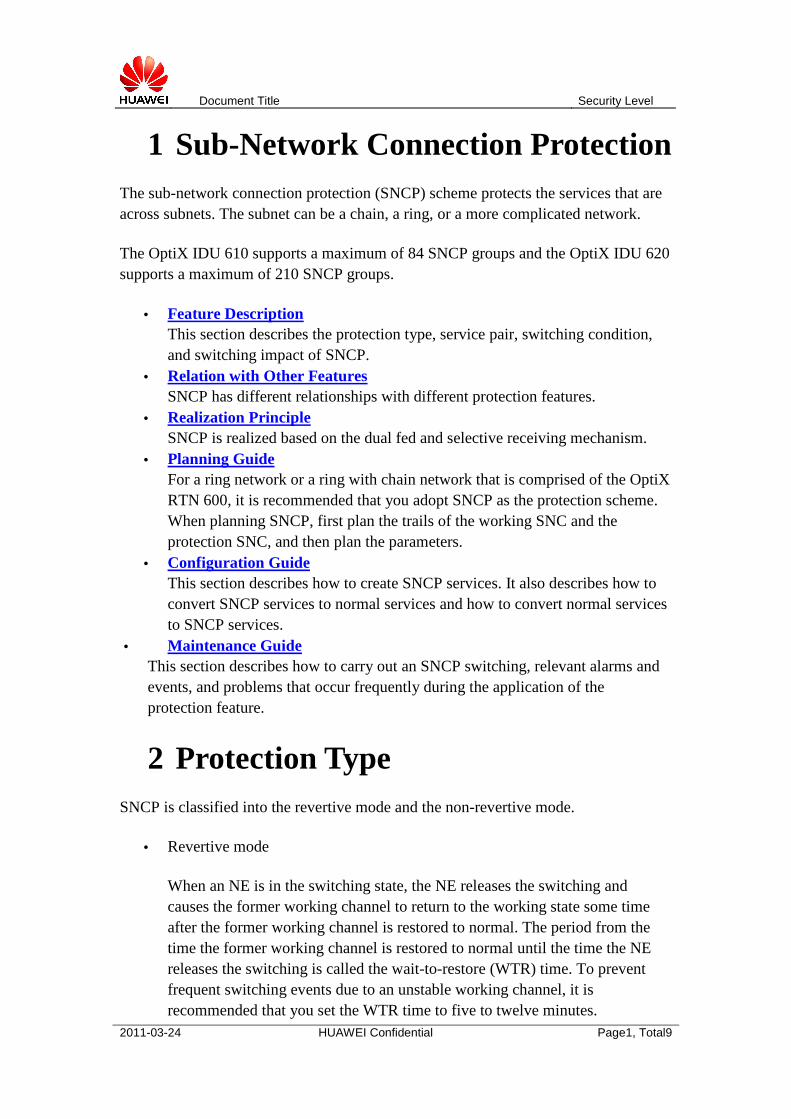
Figure 1 SNCP service pair
The working source and the protection source can be of the fiber line, STM-1e cable, or radio link, and can be of different line types. The service sink can be of any line or tributary type.
4 Switching Condition The switching priority varies according to the switching condition.
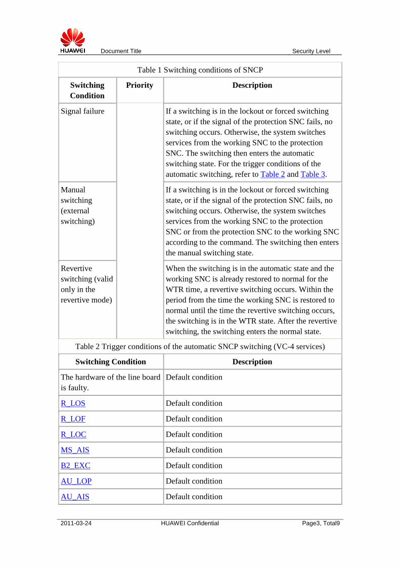
Table 1 Switching conditions of SNCP
Switching Condition
Priority Description
Clear switching (external switching)
From
top
downwards
,
the priority is from the
highest to
the lowest.
All external switching states are cleared.
Lockout switching (external switching)
In any state, a switching enters the lockout state. In the lockout state, no switching occurs until the lockout switching is cleared.
Forced switching (external switching)
If a switching is in the lockout state, no forced switching occurs. Otherwise, the system switches services from the working SNC to the protection SNC or from the protection SNC to the working SNC according to the command. The switching then enters the forced switching state.
Document Title Security Level
2011-03-24 HUAWEI Confidential Page3, Total9
Table 1 Switching conditions of SNCP
Switching Condition
Priority Description
Signal failure If a switching is in the lockout or forced switching state, or if the signal of the protection SNC fails, no switching occurs. Otherwise, the system switches services from the working SNC to the protection SNC. The switching then enters the automatic switching state. For the trigger conditions of the automatic switching, refer to Table 2 and Table 3.
Manual switching (external switching)
If a switching is in the lockout or forced switching state, or if the signal of the protection SNC fails, no switching occurs. Otherwise, the system switches services from the working SNC to the protection SNC or from the protection SNC to the working SNC according to the command. The switching then enters the manual switching state.
Revertive switching (valid only in the revertive mode)
When the switching is in the automatic state and the working SNC is already restored to normal for the WTR time, a revertive switching occurs. Within the period from the time the working SNC is restored to normal until the time the revertive switching occurs, the switching is in the WTR state. After the revertive switching, the switching enters the normal state.
Table 2 Trigger conditions of the automatic SNCP switching (VC-4 services)
Switching Condition Description
The hardware of the line board is faulty.
Default condition
R_LOS Default condition
R_LOF Default condition
R_LOC Default condition
MS_AIS Default condition
B2_EXC Default condition
AU_LOP Default condition
AU_AIS Default condition
Document Title Security Level
2011-03-24 HUAWEI Confidential Page4, Total9
Table 1 Switching conditions of SNCP
Switching Condition
Priority Description
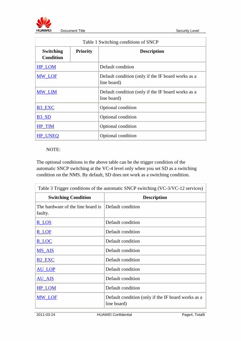
HP_LOM Default condition
MW_LOF Default condition (only if the IF board works as a line board)
MW_LIM Default condition (only if the IF board works as a line board)
B3_EXC Optional condition
B3_SD Optional condition
HP_TIM Optional condition
HP_UNEQ Optional condition
NOTE:
The optional conditions in the above table can be the trigger condition of the automatic SNCP switching at the VC-4 level only when you set SD as a switching condition on the NMS. By default, SD does not work as a switching condition.
Table 3 Trigger conditions of the automatic SNCP switching (VC-3/VC-12 services)
Switching Condition Description
The hardware of the line board is faulty.
Default condition
R_LOS Default condition
R_LOF Default condition
R_LOC Default condition
MS_AIS Default condition
B2_EXC Default condition
AU_LOP Default condition
AU_AIS Default condition
HP_LOM Default condition
MW_LOF Default condition (only if the IF board works as a line board)
Document Title Security Level
2011-03-24 HUAWEI Confidential Page5, Total9
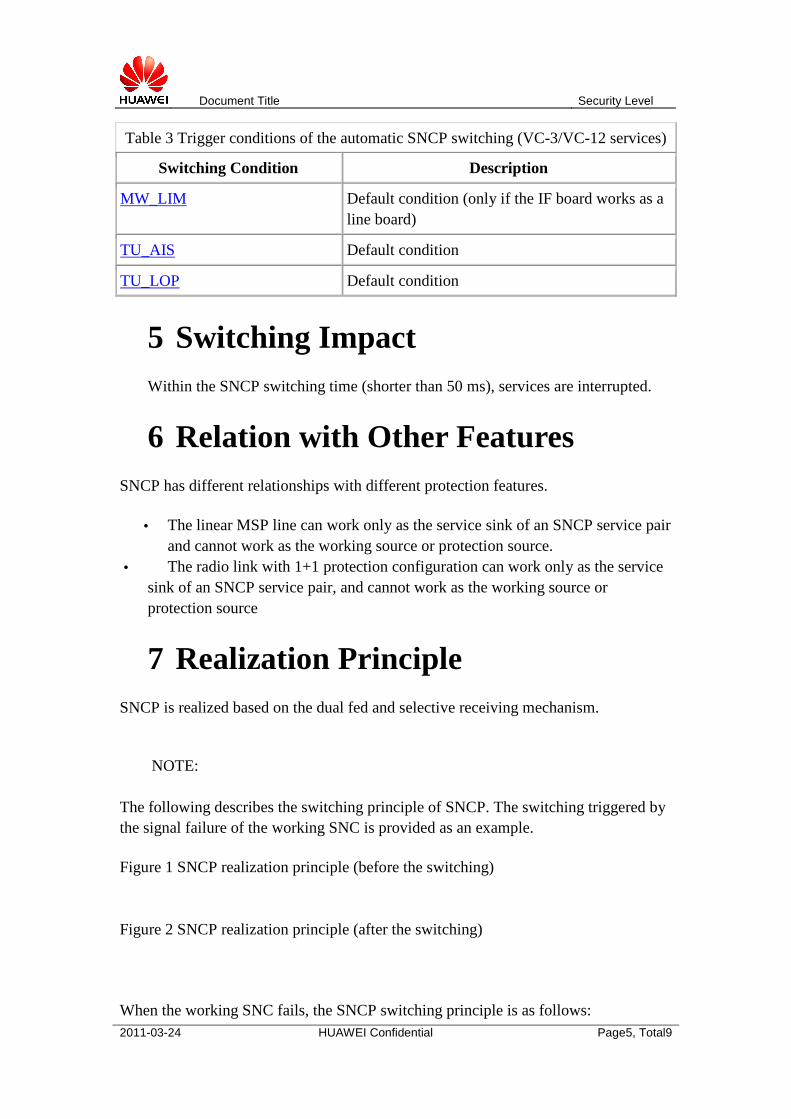
Table 3 Trigger conditions of the automatic SNCP switching (VC-3/VC-12 services)
Switching Condition Description
MW_LIM Default condition (only if the IF board works as a line board)
TU_AIS Default condition
TU_LOP Default condition
5 Switching Impact Within the SNCP switching time (shorter than 50 ms), services are interrupted.
6 Relation with Other Features SNCP has different relationships with different protection features.
• The linear MSP line can work only as the service sink of an SNCP service pair and cannot work as the working source or protection source.
• The radio link with 1+1 protection configuration can work only as the service sink of an SNCP service pair, and cannot work as the working source or protection source
7 Realization Principle SNCP is realized based on the dual fed and selective receiving mechanism.
NOTE:
The following describes the switching principle of SNCP. The switching triggered by the signal failure of the working SNC is provided as an example.
Figure 1 SNCP realization principle (before the switching)
Figure 2 SNCP realization principle (after the switching)
When the working SNC fails, the SNCP switching principle is as follows:
Document Title Security Level
2011-03-24 HUAWEI Confidential Page6, Total9
1. Before the switching, the trail source of the SNC (NE A) sends normal service signals to the trail sink (NE B) through both the working SNC and the protection SNC.
2. On detecting that the signal of the working SNC fails, the line board of NE B reports the event to the SCC board.
3. After confirming that the signal of the working SNC fails and that the signal of the protection SNC is normal, the SCC board controls the cross-connect board to complete the cross-connection between the protection SNC and the service sink.
8 Planning Guide For a ring network or a ring with chain network that is comprised of the OptiX RTN 600, it is recommended that you adopt SNCP as the protection scheme. When planning SNCP, first plan the trails of the working SNC and the protection SNC, and then plan the parameters.
Procedure
1. Plan the trails of the working SNC and the protection SNC.
Follow these two principles when planning the trails:
o Do not overlap the working SNC and the protection SNC if possible. o The OptiX RTN 600 does not support the line with the MSP or 1+1
protection configuration as the working source or protection source of SNCP.
2. Plan the parameters relevant to the protection configuration. o It is recommended that the working SNC uses the line ports of one line
board and the protection SNC uses those of another line board to prevent the situation in which failure of a line board causes the protection to fail.
o If the protection is in the revertive mode, set the WTR time to a value between five and twelve minutes. It is recommended that you set the value to ten minutes.
o It is recommended that you set SD as a switching condition.
9 Creating Cross-Connections for SNCP Services
You can create cross-connections for SNCP services by specifying the timeslot connection between the working source, protection source, and service sink.
Document Title Security Level
2011-03-24 HUAWEI Confidential Page7, Total9
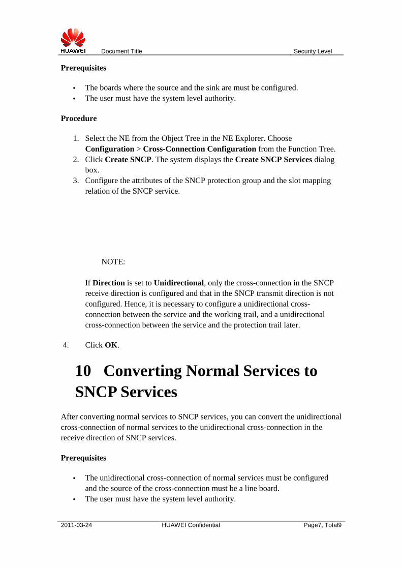
Prerequisites
• The boards where the source and the sink are must be configured. • The user must have the system level authority.
Procedure
1. Select the NE from the Object Tree in the NE Explorer. Choose Configuration > Cross-Connection Configuration from the Function Tree.
2. Click Create SNCP. The system displays the Create SNCP Services dialog box.
3. Configure the attributes of the SNCP protection group and the slot mapping relation of the SNCP service.
NOTE:
If Direction is set to Unidirectional, only the cross-connection in the SNCP receive direction is configured and that in the SNCP transmit direction is not configured. Hence, it is necessary to configure a unidirectional cross-connection between the service and the working trail, and a unidirectional cross-connection between the service and the protection trail later.
4. Click OK.
10 Converting Normal Services to SNCP Services
After converting normal services to SNCP services, you can convert the unidirectional cross-connection of normal services to the unidirectional cross-connection in the receive direction of SNCP services.
Prerequisites
• The unidirectional cross-connection of normal services must be configured and the source of the cross-connection must be a line board.
• The user must have the system level authority.
Document Title Security Level
2011-03-24 HUAWEI Confidential Page8, Total9
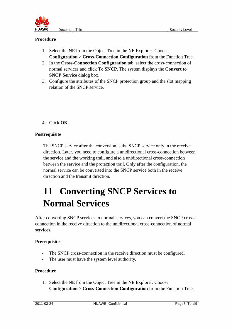
Procedure
1. Select the NE from the Object Tree in the NE Explorer. Choose Configuration > Cross-Connection Configuration from the Function Tree.
2. In the Cross-Connection Configuration tab, select the cross-connection of normal services and click To SNCP. The system displays the Convert to SNCP Service dialog box.
3. Configure the attributes of the SNCP protection group and the slot mapping relation of the SNCP service.
4. Click OK.
Postrequisite
The SNCP service after the conversion is the SNCP service only in the receive direction. Later, you need to configure a unidirectional cross-connection between the service and the working trail, and also a unidirectional cross-connection between the service and the protection trail. Only after the configuration, the normal service can be converted into the SNCP service both in the receive direction and the transmit direction.
11 Converting SNCP Services to Normal Services
After converting SNCP services to normal services, you can convert the SNCP cross-connection in the receive direction to the unidirectional cross-connection of normal services.
Prerequisites
• The SNCP cross-connection in the receive direction must be configured. • The user must have the system level authority.
Procedure
1. Select the NE from the Object Tree in the NE Explorer. Choose Configuration > Cross-Connection Configuration from the Function Tree.
Document Title Security Level
2011-03-24 HUAWEI Confidential Page9, Total9
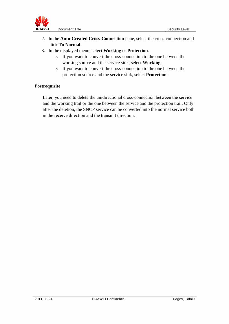
2. In the Auto-Created Cross-Connection pane, select the cross-connection and click To Normal.
3. In the displayed menu, select Working or Protection. o If you want to convert the cross-connection to the one between the
working source and the service sink, select Working. o If you want to convert the cross-connection to the one between the
protection source and the service sink, select Protection.
Postrequisite
Later, you need to delete the unidirectional cross-connection between the service and the working trail or the one between the service and the protection trail. Only after the deletion, the SNCP service can be converted into the normal service both in the receive direction and the transmit direction.


![Multi-Layer Survivabilitygrover/mesh_networking/wp008[1].pdf · titled "Multi-Layer Survivability," we specifically ... MSP SNCP MS-SPRing Distributed ... Ring. SDH Multiplex Section](https://img.pdfslide.us/doc/110x75/5abf11a57f8b9a3a428dbdc2/multi-layer-grovermeshnetworkingwp0081pdftitled-multi-layer-survivability.jpg)