Embed Size (px)
Citation preview
SMT Technical Reference Manual
MAN0019, Rev. G


SMT Technical Reference Manual Document Number: MAN0019, Rev. G
Date of Last Revision: February 28, 2007
Copyright © 1998 – 2007, Two Technologies, Inc.
All rights reserved.
Printed in the United States of America
Copyrights and Trademarks The 2T logo is a registered trademark and SMT is a trademark of Two Technologies, Inc.
Other products or company names mentioned herein may be the trademarks or registered trademarks of their respective companies.
Reproduction Rights This manual contains proprietary information. Permission to reproduce or otherwise use portions of the material presented herein is explicitly given to Two Technologies OEMs incorporating the SMT into their products. Please note that this publication contains material that may not be appropriate for disclosure to some end users and that Two Technologies assumes no responsibility for technical support burdens incurred, or any other consequences of OEM documentation decisions.
Changes and Addendum Since Two Technologies is continuously improving the functionality and quality of its products, certain information may not be included in this manual at its time of release. As a result, Two Technologies may provide changed material as separate sheets included with this manual or separately in the form of a change package, as it deems necessary.
Contact Information Two Technologies, Inc. 419 Sargon Way Horsham, PA 19044 Phone: 215 441-5305 Fax: 215 441-0423 Web: www.2T.com
To contact Two Technologies by e-mail:
• Sales: [email protected]
• Customer Service: [email protected]
• Technical Support: [email protected]
SMT Technical Reference Manual, MAN0019, Rev. G iii
Warranty Information Seller warrants that the product specified in this agreement are free of defects in materials and workmanship, and shall conform to the latest specifications published prior to Buyer’s acceptance of the agreement for a period of three years.
Product specifications as defined supersede previous specifications and are complete. Any parameter that is not specifically defined in the specifications is expressly excluded from the warranty. This warranty does not apply to any product which have been subject to misuse, accident, alteration, or if the unit has been serviced by anyone other than an authorized representative of Seller.
Seller’s sole obligation to Buyer for products failing to meet specifications shall be, at Seller’s discretion, to repair or replace the non-conforming device.
After receiving a Return Authorization (RA) number and a mailing address from Seller, a defective unit covered under this warranty may be returned freight prepaid. Any replacement or repaired product shall carry only the unexpired term of the warranty plus any the period required for repair.
If Buyer has been expressly designated as an Original Equipment Manufacturer (OEM) by Seller, the warranty period shall commence upon the earlier date of (i) delivery to Buyer’s first customer, or (ii) 180 days from the original date of shipment by Seller. In the events that products for which: (a) Buyer has title and, (b) have never been used, and (c) have been in the Buyer’s possession for more than 180 days and, (d) have an unaltered date code attached, may for an established fixed fee which will not exceed ten percent (10%) of the original purchase price, have the date code updated by the Seller and thereby reestablish those products with a new warranty.
THE FOREGOING WARRANTY AND REMEDIES ARE EXCLUSIVE AND ARE MADE EXPRESSLY IN LIEU OF ALL OTHER WARRANTIES EXPRESSED OR IMPLIED, EITHER IN FACT OR BY OPERATION OF LAW, STATUTORY OR OTHERWISE, INCLUDING WARRANTIES OR MERCHANTABILITY AND FITNESS FOR USE. TWO TECHNOLOGIES NEITHER ASSUMES NOR AUTHORIZES ANY OTHER PERSON TO ASSUME FOR IT ANY OTHER LIABILITY IN CONNECTION WITH THE SALE, INSTALLATION OR USE OF ITS PRODUCTS AND TWO TECHNOLOGIES MAKES NO WARRANTY WHATSOEVER FOR PRODUCTS NOT MANUFACTURED BY TWO TECHNOLOGIES.
TWO TECHNOLOGIES SHALL NOT BE LIABLE FOR DAMAGES DUE TO DELAYS IN DELIVERIES OR USE AND SHALL IN NO EVENT BE LIABLE FOR INCIDENTAL OR CONSEQUENTIAL DAMAGES OF ANY KIND, WHETHER ARISING FROM CONTRACT, TORT OR NEGLIGENCE, INCLUDING, BUT NOT LIMITED TO, LOSS OF PROFITS, LOSS OF GOODWILL, OVERHEAD OR OTHER LIKE DAMAGES.
To maintain your warranty and to avoid creating hazards, only qualified personnel should perform authorized modifications to Two Technologies’ products. Two Technologies cannot assume responsibility for any condition affecting the proper operation of this equipment that may result from unauthorized modifications.
Product Returns If, after inspection, you note any product damage or discrepancies, please contact us promptly within five days of receipt. If the exterior of the package shows obvious signs of damage, please contact your carrier directly.
All items returned to Two Technologies require a Return Material Authorization number (RMA). Please contact Two Technologies’ Service department to request an RMA number.
SMT Technical Reference Manual, MAN0019, Rev. G iv

Regulatory Notices FCC Compliance This equipment has been tested and found to comply with the limits for Class A digital device, pursuant to Part 15 of the FCC Rules. These limits are designed to provide reasonable protection against harmful interference when the equipment is operated in a commercial environment. This equipment generates, uses, and can radiate radio frequency energy and, if not installed in accordance with the instruction manual, may cause harmful interference to radio communications. Operation of this equipment in a residential area is likely to cause harmful interference, in which case the user will be required to correct the interference at his or her own expense.
Canadian Compliance This digital apparatus does not exceed the Class A limits for radio noise emissions from digital apparatus set out in the Radio Interference Regulations of the Canadian Department of Communications
Le present appareil numerique n.emet pas de bruits radioelectrique depassant les limites applicables aux appareils numeriques de la class A prescrites dans le Reglement sur ie broullage radioelectrique edicte par le ministere des Communications du Canada.
Certifications CENELEC
EMI Standards • EN55022: 1998 (CISPR22, Class B) Information Technology
EMC Standards • EN50082-1: 1997, General Immunity Part 1
Safety Standard • EN60950: 2000 Safety of Information Technology Equipment
Warnings Changes or modifications to this unit, which are not expressly approved by the party responsible for regulatory compliance, could void the user's authority to operate the equipment.
Electrostatic Discharge (ESD)
Electrostatic discharge (static electricity) can have unpredictable adverse effects on any electronic device. Although the design of the SMT incorporates extensive ESD-related precautions, ESD can still cause problems. It is good practice to discharge static by touching a grounded metal object before inserting cards or connecting devices.
SMT Technical Reference Manual, MAN0019, Rev. G v
Product Selection Guide The SMT series is line of ASCII terminals for use with computers, properly equipped instruments and industrial machinery.
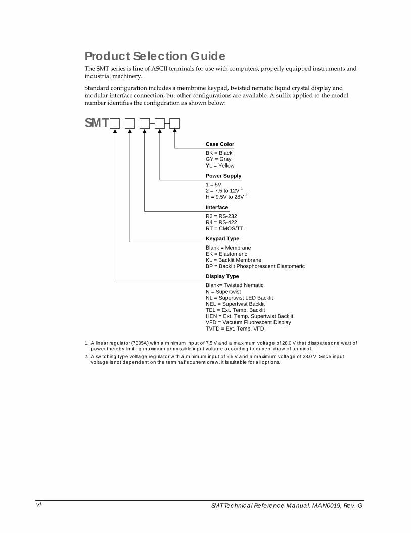
Standard configuration includes a membrane keypad, twisted nematic liquid crystal display and modular interface connection, but other configurations are available. A suffix applied to the model number identifies the configuration as shown below:
SMT Case Color BK = Black GY = Gray YL = Yellow
Power Supply 1 = 5V 2 = 7.5 to 12V 1H = 9.5V to 28V 2
Interface R2 = RS-232 R4 = RS-422 RT = CMOS/TTL
Keypad Type Blank = Membrane EK = Elastomeric KL = Backlit Membrane BP = Backlit Phosphorescent Elastomeric
Display Type Blank= Twisted Nematic N = Supertwist NL = Supertwist LED Backlit NEL = Supertwist Backlit TEL = Ext. Temp. Backlit HEN = Ext. Temp. Supertwist Backlit VFD = Vacuum Fluorescent Display TVFD = Ext. Temp. VFD
1. A linear regulator (7805A) with a minimum input of 7.5 V and a maximum voltage of 28.0 V that dissipates one watt of power thereby limiting maximum permissible input voltage according to current draw of terminal.
2. A switching type voltage regulator with a minimum input of 9.5 V and a maximum voltage of 28.0 V. Since input voltage is not dependent on the terminal’s current draw, it is suitable for all options.
SMT Technical Reference Manual, MAN0019, Rev. G vi

Power Requirements Power Supply Options Depending on the current draw requirements, the terminal may require the use of different power supplies. Use the configuration number listed below (see previous page) to determine the correct power supply:
• "-1"—requires connection to a 5-volt ± 5% regulated power source.
• "-2"—requires connection to a power source between 7.5 and 12 VDC that can source adequate current. However, depending on a unit's total current draw, an input of up to 28 VDC may be applied. See chart on next page.
• "-H"—requires connection to a power source between 9.5 and 28 VDC that can source adequate current. However, input voltage is not dependent on a terminal’s current draw and may be used with all terminal options. This power supply is strongly recommended for terminals equipped with a Vacuum Fluorescent Display.
Calculating Total Current Draw The table below summarizes the current draw requirements for SMT terminals in various configurations (measured at its interface connector). Values listed are approximate due to variations in individual components—actual values may vary.
Current Draw for Basic Configuration Configuration Description Draw SMTR2 Base Unit with RS-232 40 mA
SMTR4 Base Unit with RS-422 20 mA
Current Draw for Options NL Supertwist LED Backlit Add 185 mA
NEL/HEN Supertwist Backlit/Extended Temperature Supertwist Backlit Add 40 mA
VFD/TVFD Vacuum Fluorescent Display/Extended Temperature VFD Add 300 mA
KL Backlit Keypad Add 80 mA
External Speaker (when activated) Add 20 mA
Handshake Floating (not connected) Add 1 mA
Handshake Low Condition Add 3 mA
To calculate the total current draw for your terminal configuration:
1. Read the model number on the back of your terminal.
2. Using the model number and the table above, add the current draw for each option to that of the base unit.
Example 1—SMTNELR2: RS-232 Option 40 mA Supertwist Backlit Display 40 mA Calculated Total Current 80 mA
Example 2—SMTVFDR2: RS-232 Option 40 mA Supertwist LED Backlit Display 300 mA Calculated Total Current 340 mA
SMT Technical Reference Manual, MAN0019, Rev. G vii
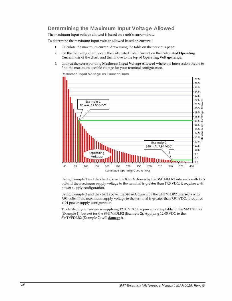
Determining the Maximum Input Voltage Allowed The maximum input voltage allowed is based on a unit’s current draw.
To determine the maximum input voltage allowed based on current:
1. Calculate the maximum current draw using the table on the previous page.
2. On the following chart, locate the Calculated Total Current on the Calculated Operating Current axis of the chart, and then move to the top of Operating Voltage range.
3. Look at the corresponding Maximum Input Voltage Allowed where the intersection occurs to find the maximum useable voltage for your terminal configuration.
Restricted Input Voltage vs. Current Draw
7.58.59.510.511.512.513.514.515.516.517.518.519.520.521.522.523.524.525.526.527.5
4003703403102802502201901601301007040Calculated Operating Current (mA)
Max
imum
Inpu
t Vol
tage
Allo
wed
Using Example 1 and the chart above, the 80 mA drawn by the SMTNELR2 intersects with 17.5 volts. If the maximum supply voltage to the terminal is greater than 17.5 VDC, it requires a -H power supply configuration.
Using Example 2 and the chart above, the 340 mA drawn by the SMTVFDR2 intersects with 7.94 volts. If the maximum supply voltage to the terminal is greater than 7.94 VDC, it requires a -H power supply configuration.
To clarify, if your system is supplying 12.00 VDC, the power is acceptable for the SMTNELR2 (Example 1), but not for the SMTVFDLR2 (Example 2). Applying 12.00 VDC to the SMTVFDLR2 (Example 2) will damage it.
Operating Voltage
Example 2 340 mA, 7.94 VDC
Example 1 80 mA, 17.50 VDC
SMT Technical Reference Manual, MAN0019, Rev. G viii
Contents Chapter 1: Overview .........................................................................................................1-1
About this Manual ..........................................................................................................................................1-1 About Two Technologies ...............................................................................................................................1-1 About the SMT ................................................................................................................................................1-2
SMT Features ..............................................................................................................................................1-2 Chapter 2: Operation ........................................................................................................2-1
Controls and Indicators..................................................................................................................................2-1 Cable and Power Connections ......................................................................................................................2-2
Internal Connections ..................................................................................................................................2-2 Internal Communication Devices.............................................................................................................2-3 Signal and Pin Assignments......................................................................................................................2-4 Connecting the Terminal ...........................................................................................................................2-5
Power................................................................................................................................................................2-6 Keypad Operation ..........................................................................................................................................2-7
Key Output..................................................................................................................................................2-7 Display Operation...........................................................................................................................................2-8
Cursor Position ...........................................................................................................................................2-8 Operating Modes ............................................................................................................................................2-8 Host Control ....................................................................................................................................................2-8
Chapter 3: Terminal Configuration...................................................................................3-1 Introduction.....................................................................................................................................................3-1 Parameter Menu Settings...............................................................................................................................3-1
Baud Rate.....................................................................................................................................................3-1 Data Bits.......................................................................................................................................................3-1 Parity ............................................................................................................................................................3-1 Display PE ...................................................................................................................................................3-1 Repeat ..........................................................................................................................................................3-2 Echo..............................................................................................................................................................3-2 Handshake...................................................................................................................................................3-2 Self-Test........................................................................................................................................................3-2 Parameter Menu Summary .......................................................................................................................3-2
Changing Parameter Settings........................................................................................................................3-3 Loading Factory Default Settings .................................................................................................................3-3 Restricting Access ...........................................................................................................................................3-4 Key Programming...........................................................................................................................................3-4
Chapter 4: Host Commands .............................................................................................4-1 Introduction.....................................................................................................................................................4-1 Escape Commands..........................................................................................................................................4-1
Cursor Up....................................................................................................................................................4-1 Cursor Down...............................................................................................................................................4-1 Cursor Right................................................................................................................................................4-1 Cursor Left ..................................................................................................................................................4-1 Cursor Home & Clear Display..................................................................................................................4-1 Enable Underscore Cursor ........................................................................................................................4-2 Disable Underscore Cursor .......................................................................................................................4-2 Cursor Home...............................................................................................................................................4-2 Clear Display...............................................................................................................................................4-2 Erase Cursor to End of Display ................................................................................................................4-2 Erase Cursor to End of Line ......................................................................................................................4-2 Sound Long Bell..........................................................................................................................................4-2 Erase Line Containing Cursor...................................................................................................................4-2 Sound Click .................................................................................................................................................4-2 Sound Alert .................................................................................................................................................4-2
SMT Technical Reference Manual, MAN0019, Rev. G ix
Enable Blinking Cursor..............................................................................................................................4-2 Disable Blinking Cursor ............................................................................................................................4-3 Sound Short Bell .........................................................................................................................................4-3 Enable Key Click.........................................................................................................................................4-3 Disable Key Click .......................................................................................................................................4-3 Cursor Position ...........................................................................................................................................4-3 Send Terminal ID .......................................................................................................................................4-4 Enable Backlight .........................................................................................................................................4-4 Disable Backlight ........................................................................................................................................4-4 Host Command Summary ........................................................................................................................4-4
Control Codes..................................................................................................................................................4-5 Chapter 5: Mounting the SMT........................................................................................... 5-1
Introduction.....................................................................................................................................................5-1 Mounting Configurations..........................................................................................................................5-1
Permanent Mounting .....................................................................................................................................5-1 Mounting Kit...............................................................................................................................................5-1 Mounting Template ...................................................................................................................................5-2 Permanent Closed Back Flush Mounting................................................................................................5-3 Permanent Open Back Flush Mounting ..................................................................................................5-4
Detachable Mounting.....................................................................................................................................5-5 Horizontal Mounting.................................................................................................................................5-5 Vertical Mounting ......................................................................................................................................5-6
Chapter 6: Troubleshooting.............................................................................................. 6-1 Appendix A: Specifications .............................................................................................A-1 Appendix B: ASCII Character Set .................................................................................... B-1
Introduction.................................................................................................................................................... B-1 Index .................................................................................................................................. I-1
List of Figures Figure 2-1: SMT Controls and Indicators .................................................................................................2-1 Figure 2-2: Header Locations.....................................................................................................................2-2 Figure 2-3: I/O Header Connection..........................................................................................................2-2 Figure 2-4: Modular Interface Connector.................................................................................................2-4 Figure 2-5: 1210 Series Modular Cable .....................................................................................................2-5 Figure 2-6: PCAT Modular Connector .....................................................................................................2-5 Figure 2-7: Cable Connections...................................................................................................................2-6 Figure 2-8: Standard 20-Position Keypad ................................................................................................2-7 Figure 3-1: Parity Error Symbol.................................................................................................................3-1 Figure 5-1: SMT Mounting Kit...................................................................................................................5-2 Figure 5-2: SMT ANSI Series Terminal Permanent Mount Template ..................................................5-2 Figure 5-3: Flush Mount, Closed Back Mounting ...................................................................................5-3 Figure 5-4: Flush Mount, Closed Back Mounting ...................................................................................5-4 Figure 5-5: Horizontal Detachable Mounting Template ........................................................................5-5 Figure 5-6: Horizontal Detachable Mount, Top View ............................................................................5-5 Figure 5-7: Horizontal Detachable Mount, Front View..........................................................................5-6 Figure 5-8: Vertical Detachable Mounting Template..............................................................................5-6 Figure 5-9: Vertical Detachable Mount, Top View..................................................................................5-7 Figure 5-10: Vertical Detachable Mount, Front View .............................................................................5-7 Figure A-1: SMT Case Dimensions ..........................................................................................................A-2
SMT Technical Reference Manual, MAN0019, Rev. G x
List of Tables Table 2-1: SMT Controls and Indicators ...................................................................................................2-1 Table 2-2: I/O Header Connections..........................................................................................................2-3 Table 2-3: Extended Voltage Header Connections..................................................................................2-3 Table 2-4: Interface Devices........................................................................................................................2-3 Table 2-5: Modular Interface Connector Signal and Pin Assignments.................................................2-4 Table 2-6: Key Output Table ......................................................................................................................2-7 Table 3-1: Parameter Menu Summary ......................................................................................................3-2 Table 4-1: Host Command Summary .......................................................................................................4-4 Table 4-2: Control Codes ............................................................................................................................4-5 Table 5-1: Mounting Kit..............................................................................................................................5-1 Table B-1: ASCII Character Set and Conversion Codes ........................................................................ B-1
SMT Technical Reference Manual, MAN0019, Rev. G xi

SMT Technical Reference Manual, MAN0019, Rev. G
Chapter 1: Overview
About this Manual Intended for developers familiar with operator interface applications, this manual describes the advanced features, operations and interface capabilities of Two Technologies’ SMT terminals. It is not for use by end-users.
Unless otherwise stated, the operational characteristics described herein correspond to factory default configurations and settings as shipped from Two Technologies.
Because SMT terminals are highly customizable products with several optional configurations and special keypad layouts, this manual only describes standard features and operation. For custom configurations and special options, consult the appropriate supplemental manual or addendum.
It is beyond the scope of this manual to provide operating system tutorials or information about commercial or customized SMT application programs and connected equipment. This information should be available in the manuals that accompany those products.
Wherever used herein, the term “SMT” applies to all models (except as noted).
Symbols and Conventions Unless otherwise noted, this manual uses the following format conventions to distinguish elements of text:
• New terms used in this manual initially appear in Italics, for example: host.
• Names of keys as shown on a keypad appear in bold type, for example: CTRL.
• Names of parameter values appear in uppercase letters, for example: ENABLE.
• Esc represents the ASCII escape character in Escape commands, for example: Esc [4n.
• A lowercase “h” appearing after a number denotes a hexadecimal value, for example: 1Bh.
Related Manuals • SMT ANSI Technical Reference Manual
About Two Technologies Two Technologies has been producing rugged hand held and panel mount terminals and computers for over fifteen years. By implementing state of the art design and manufacturing techniques, we revolutionized hand held terminals and computers inside and out. Today, Two Technologies offers over a dozen cost-effective solutions serving virtually every market.
1-1
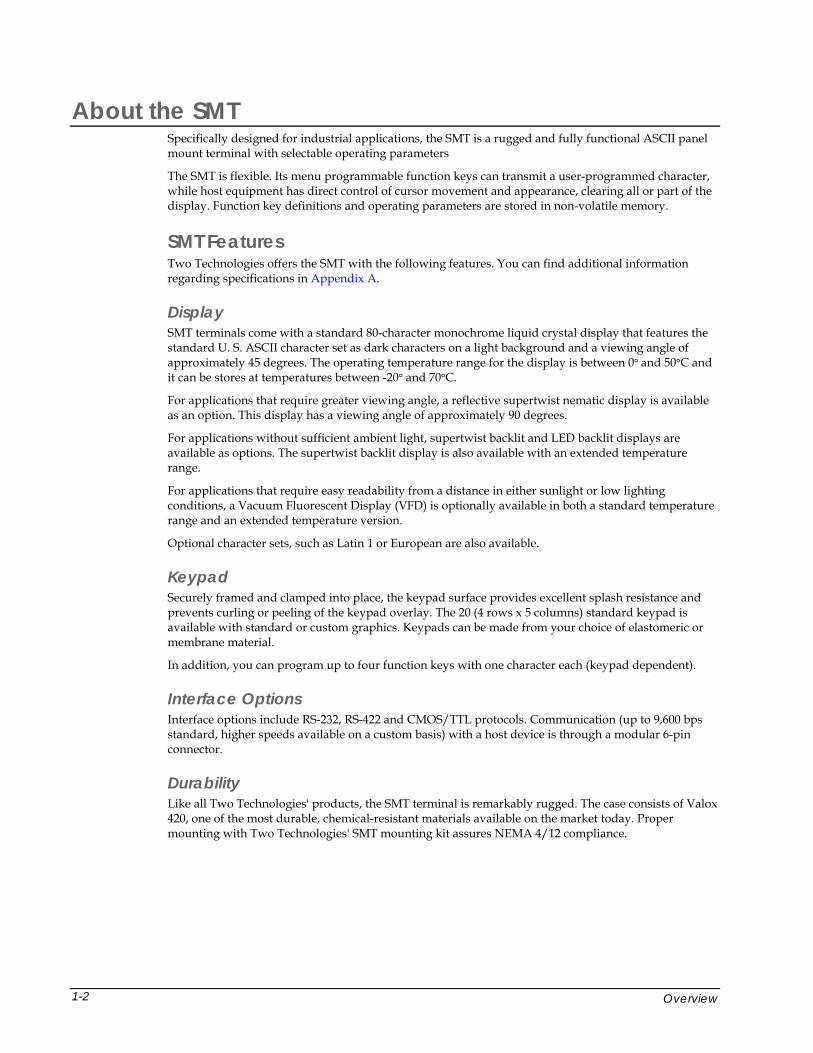
About the SMT Specifically designed for industrial applications, the SMT is a rugged and fully functional ASCII panel mount terminal with selectable operating parameters
The SMT is flexible. Its menu programmable function keys can transmit a user-programmed character, while host equipment has direct control of cursor movement and appearance, clearing all or part of the display. Function key definitions and operating parameters are stored in non-volatile memory.
SMT Features Two Technologies offers the SMT with the following features. You can find additional information regarding specifications in Appendix A.
Display SMT terminals come with a standard 80-character monochrome liquid crystal display that features the standard U. S. ASCII character set as dark characters on a light background and a viewing angle of approximately 45 degrees. The operating temperature range for the display is between 0° and 50°C and it can be stores at temperatures between -20° and 70°C.
For applications that require greater viewing angle, a reflective supertwist nematic display is available as an option. This display has a viewing angle of approximately 90 degrees.
For applications without sufficient ambient light, supertwist backlit and LED backlit displays are available as options. The supertwist backlit display is also available with an extended temperature range.
For applications that require easy readability from a distance in either sunlight or low lighting conditions, a Vacuum Fluorescent Display (VFD) is optionally available in both a standard temperature range and an extended temperature version.
Optional character sets, such as Latin 1 or European are also available.
Keypad Securely framed and clamped into place, the keypad surface provides excellent splash resistance and prevents curling or peeling of the keypad overlay. The 20 (4 rows x 5 columns) standard keypad is available with standard or custom graphics. Keypads can be made from your choice of elastomeric or membrane material.
In addition, you can program up to four function keys with one character each (keypad dependent).
Interface Options Interface options include RS-232, RS-422 and CMOS/TTL protocols. Communication (up to 9,600 bps standard, higher speeds available on a custom basis) with a host device is through a modular 6-pin connector.
Durability Like all Two Technologies' products, the SMT terminal is remarkably rugged. The case consists of Valox 420, one of the most durable, chemical-resistant materials available on the market today. Proper mounting with Two Technologies' SMT mounting kit assures NEMA 4/12 compliance.
Overview 1-2
SMT Technical Reference Manual, MAN0019, Rev. G
Chapter 2: Operation
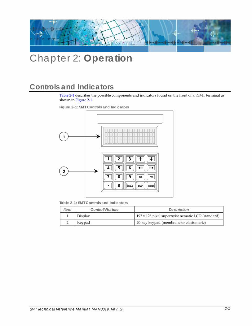
Controls and Indicators Table 2-1 describes the possible components and indicators found on the front of an SMT terminal as shown in Figure 2-1.
Figure 2-1: SMT Controls and Indicators
F4F3
F2
Table 2-1: SMT Controls and Indicators
Item Control/Feature Description 1 Display 192 x 128 pixel supertwist nematic LCD (standard)
2 Keypad 20-key keypad (membrane or elastomeric)
2
1
2-1
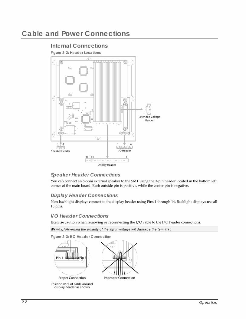
Cable and Power Connections Internal Connections Figure 2-2: Header Locations
11416
Display Header
1 6
I/O Header
1 3
Speaker Header
+ - +
Extended VoltageHeader
1
Speaker Header Connections You can connect an 8-ohm external speaker to the SMT using the 3-pin header located in the bottom left corner of the main board. Each outside pin is positive, while the center pin is negative.
Display Header Connections Non-backlight displays connect to the display header using Pins 1 through 14. Backlight displays use all 16 pins.
I/O Header Connections Exercise caution when removing or reconnecting the I/O cable to the I/O header connections.
Warning! Reversing the polarity of the input voltage will damage the terminal.
Figure 2-3: I/O Header Connection
Operation 2-2
Table 2-2: I/O Header Connections
Pin RS-232/ TTL RS-422 1 Common Common
2 Data In - Data In
3 Data Out - Data Out
4 Handshake Out + Data
5 Handshake In + Data In
6 + Supply + Supply
Extended Voltage Header Connections The extended voltage header provides connection to an internal DC-to-DC converter, which allows an external source to supply voltages up to 28 volts (i.e., Two Technologies’ -H power supply).
Note: Only use this connector with a -H power supply from Two Technologies. Any other use of this connection will void the terminal’s warranty.
Warning! Reversing polarity of the input voltage will damage the terminal.
Table 2-3: Extended Voltage Header Connections
Pin Purpose 1 Output voltage from remote regulator
2 Common (ground)
3 Input voltage from remote regulator
Internal Communication Devices The following table lists the internal interface devices used in the SMT terminal.
Table 2-4: Interface Devices Interface Manufacturer Device
RS-232 Linear Technology LT1281
RS-422 Linear Technology LTC490
SMT Technical Reference Manual, MAN0019, Rev. G 2-3
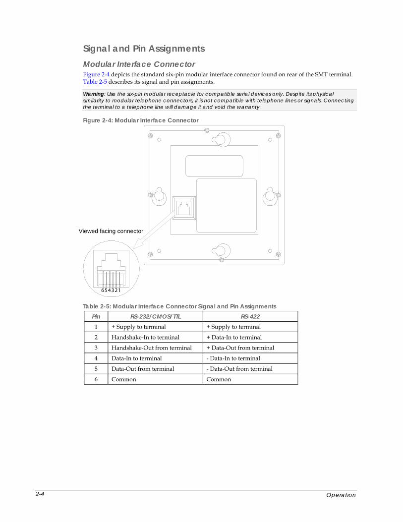
Signal and Pin Assignments Modular Interface Connector Figure 2-4 depicts the standard six-pin modular interface connector found on rear of the SMT terminal. Table 2-5 describes its signal and pin assignments.
Warning: Use the six-pin modular receptacle for compatible serial devices only. Despite its physical similarity to modular telephone connectors, it is not compatible with telephone lines or signals. Connecting the terminal to a telephone line will damage it and void the warranty.
Figure 2-4: Modular Interface Connector
2-4
Viewed facing connector
654321
Table 2-5: Modular Interface Connector Signal and Pin Assignments Pin RS-232/CMOS/TTL RS-422 1 + Supply to terminal + Supply to terminal
2 Handshake-In to terminal + Data-In to terminal
3 Handshake-Out from terminal + Data-Out from terminal
4 Data-In to terminal - Data-In to terminal
5 Data-Out from terminal - Data-Out from terminal
6 Common Common
Operation
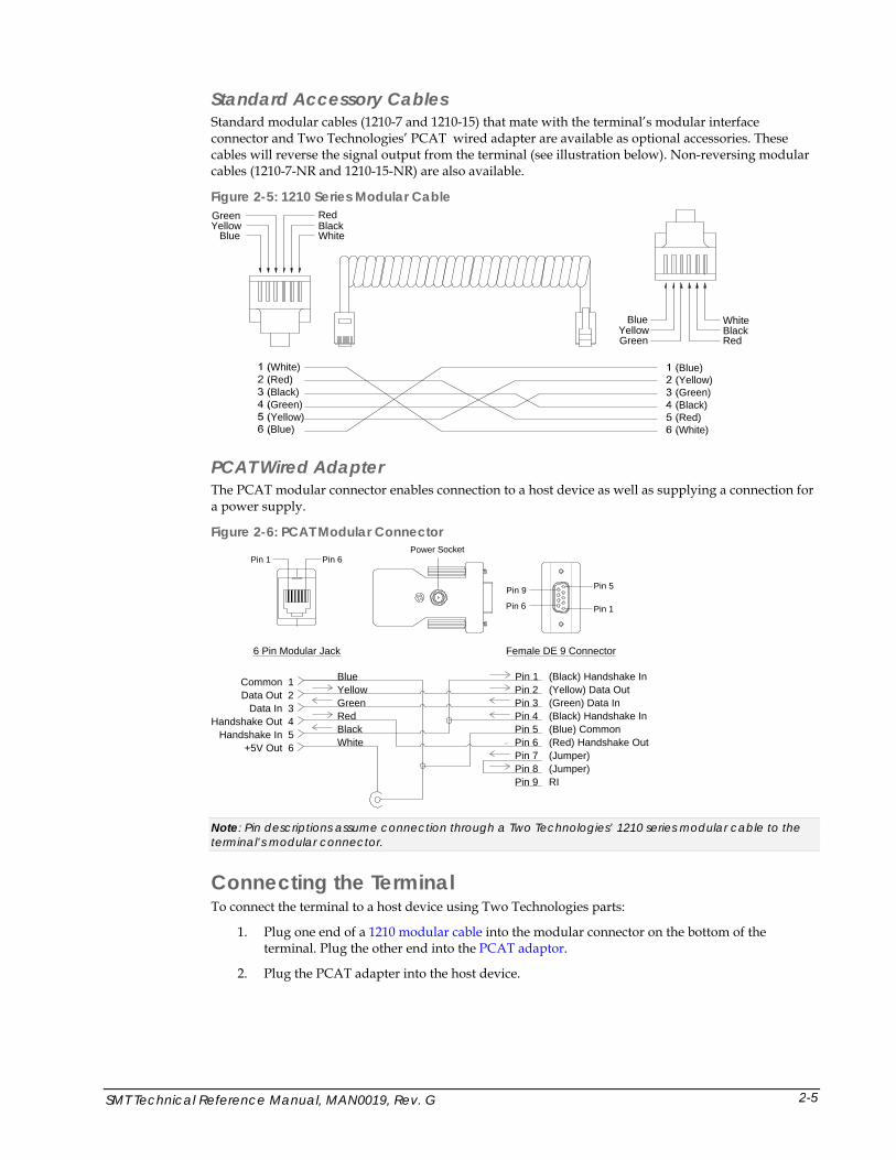
Standard Accessory Cables Standard modular cables (1210-7 and 1210-15) that mate with the terminal’s modular interface connector and Two Technologies’ PCAT wired adapter are available as optional accessories. These cables will reverse the signal output from the terminal (see illustration below). Non-reversing modular cables (1210-7-NR and 1210-15-NR) are also available.
Figure 2-5: 1210 Series Modular Cable
BlueYellowGreen Red
BlackWhite
YellowGreen
Blue
RedBlackWhite
White)Red)Black)Green)Yellow)Blue)
Blue)Yellow)Green)Black)Red)White)
PCAT Wired Adapter The PCAT modular connector enables connection to a host device as well as supplying a connection for a power supply.
Figure 2-6: PCAT Modular Connector
6 Pin Modular Jack Female DE 9 Connector
Common 1Data Out 2
Data In 3Handshake Out 4
Handshake In 5+5V Out 6
Pin 1Pin 6
Pin 9 Pin 5
Pin 1 Pin 6Power Socket
Blue Pin 1 (Black) Handshake InYellow Pin 2 (Yellow) Data OutGreen Pin 3 (Green) Data InRed Pin 4 (Black) Handshake InBlack Pin 5 (Blue) CommonWhite Pin 6 (Red) Handshake Out
Pin 7 (Jumper)Pin 8 (Jumper)Pin 9 RI
Note: Pin descriptions assume connection through a Two Technologies’ 1210 series modular cable to the terminal’s modular connector.
Connecting the Terminal To connect the terminal to a host device using Two Technologies parts:
1. Plug one end of a 1210 modular cable into the modular connector on the bottom of the terminal. Plug the other end into the PCAT adaptor.
2. Plug the PCAT adapter into the host device.
SMT Technical Reference Manual, MAN0019, Rev. G 2-5
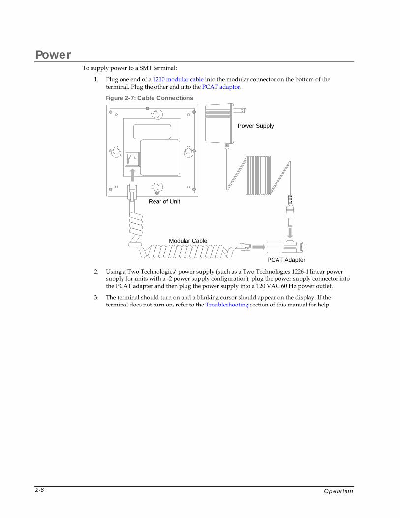
Power To supply power to a SMT terminal:
1. Plug one end of a 1210 modular cable into the modular connector on the bottom of the terminal. Plug the other end into the PCAT adaptor.
Figure 2-7: Cable Connections
Modular Cable
PCAT Adapter
Power Supply
Rear of Unit
2. Using a Two Technologies’ power supply (such as a Two Technologies 1226-1 linear power
supply for units with a -2 power supply configuration), plug the power supply connector into the PCAT adapter and then plug the power supply into a 120 VAC 60 Hz power outlet.
3. The terminal should turn on and a blinking cursor should appear on the display. If the terminal does not turn on, refer to the Troubleshooting section of this manual for help.
Operation 2-6
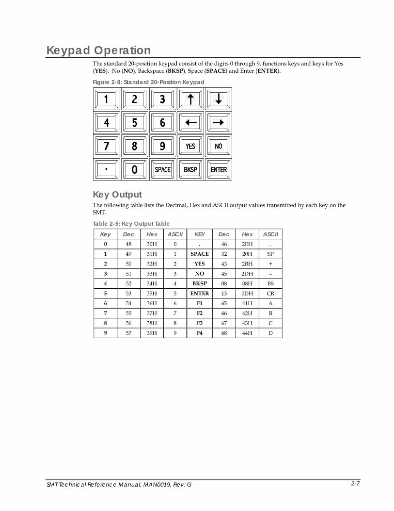
Keypad Operation The standard 20-position keypad consist of the digits 0 through 9, functions keys and keys for Yes (YES), No (NO), Backspace (BKSP), Space (SPACE) and Enter (ENTER).
Figure 2-8: Standard 20-Position Keypad
F4F3
F2
Key Output The following table lists the Decimal, Hex and ASCII output values transmitted by each key on the SMT.
Table 2-6: Key Output Table
Key Dec Hex ASCII KEY Dec Hex ASCII 0 48 30H 0 . 46 2EH .
1 49 31H 1 SPACE 32 20H SP
2 50 32H 2 YES 43 2BH +
3 51 33H 3 NO 45 2DH –
4 52 34H 4 BKSP 08 08H BS
5 53 35H 5 ENTER 13 0DH CR
6 54 36H 6 F1 65 41H A
7 55 37H 7 F2 66 42H B
8 56 38H 8 F3 67 43H C
9 57 39H 9 F4 68 44H D
SMT Technical Reference Manual, MAN0019, Rev. G 2-7
Display Operation Standard SMT terminals display the U.S. ASCII 96 character set. However, other character sets, such as such as Latin 1 or European, are also available as an option. Characters appear on the display at the current cursor location.
Cursor Position Typically, the cursor moves from left to right as the terminal displays characters (unless altered by Escape commands). The cursor is selectable as a block (enabled), hidden (disabled), blinking and non-blinking.
Whenever a character appears in the last position of the top three rows, the cursor will move to the leftmost position on the next row. By default, the terminal will hide the character in the last position on the bottom row (Position 80) with the cursor until it displays the next character. In which case, the screen will scroll up one row, the hidden character will appear in Position 80 and the cursor will appear in the rightmost position on a new bottom row. As an option, you can display a character in Position 80 and hide the cursor before the terminal display the next character.
For additional information about cursor and display options, see Chapter 3: Manual Configuration, and Chapter 5: Host Commands.
Operating Modes SMT terminals have several operating modes. The default mode is Terminal mode. It allows the terminal to display characters, respond to commands sent by a connecting device, and send characters to the connecting device as keys are pressed. Other modes, described later in this manual, enable you to set operating parameters and program function key definitions.
Host Control The design of SMT terminals allows a connecting device (or “host”) to control its functions through the transmission of a string of special characters. Referred to as “Escape commands” (because each character string begins with the ASCII escape character), these character strings enable the host to move the cursor to any position on the display, clear selected regions of the display, sound a beep, alert or key click, program the function keys and set any of the operating parameters.
Operation 2-8
SMT Technical Reference Manual, MAN0019, Rev. G
Chapter 3: Terminal Configuration
Introduction A comprehensive set of user-settable operating parameters and programmable function keys makes the SMT terminal suitable for diverse applications. Each settable parameter and programmable function key has a default value. These values are stored in the terminal's permanent memory.
This chapter describes each operating parameter in detail, as well as how to set the parameters and load the default values. Chapter 4 covers programmable function keys.
Parameter Menu Settings The following section describes the parameters that you can program in an SMT terminal. A summary (Table 3-1) appears at the end of the section.
Baud Rate This parameter sets the number of bits per second transmitted. The data rate can be set to: 300, 600, 1200, 2400, 4800 or 9600 baud. The default value is 9600.
Data Bits This parameter sets the number of data bits transmitted per character, either seven (7) or eight (8). The default value is eight.
Parity This parameter enables/disables the host’s ability to perform error checking on incoming characters and ensure accuracy. Allowable settings are NONE, EVEN, ODD, MARK and SPACE. The default value is NONE.
Selecting NONE will prevent the sending of the parity bit. In either case, the host will not perform an error check on incoming characters.
Display PE When using parity checking (EVEN, ODD, MARK or SPACE), you can enable/disable this parameter to display a special character (Figure 3-1) when a parity error occurs. The default value is ENABLED.
Figure 3-1: Parity Error Symbol
3-1
Repeat This parameter determines the repeat keypad character rate while the key remains pressed. The allowable values are SLOW (10 characters per second), FAST (18 characters per second) and DISABLED. When using REPEAT, there is a short delay between the initial character and the start of the repeat.
Echo This parameter enables/disables the terminal’s ability to display (echo) keypad entries on the screen and for use in half-duplex installations. The default value is DISABLED.
Handshake This parameter enables/disables use of handshake lines (DTR-DSR or RTS-CTS) for SMT terminals with an RS-232 interface. The default value is ENABLED.
With handshaking enabled, the terminal will not send characters until the host asserts the Handshake Input line. If the terminal is temporarily unable to process incoming characters, it will turn off the Handshake Output line. As a result, any characters sent in this state will be lost.
When set to DISABLED, the terminal will continuously assert the Handshake Output line and ignore the Handshake Input line.
Self-Test This setting determines if the terminal will perform a confidence test at boot-up. The test initially displays the U.S. ASCII character set and then performs a number of internal tests. If an error occurs, the terminal will display an error message. The default value is DISABLED
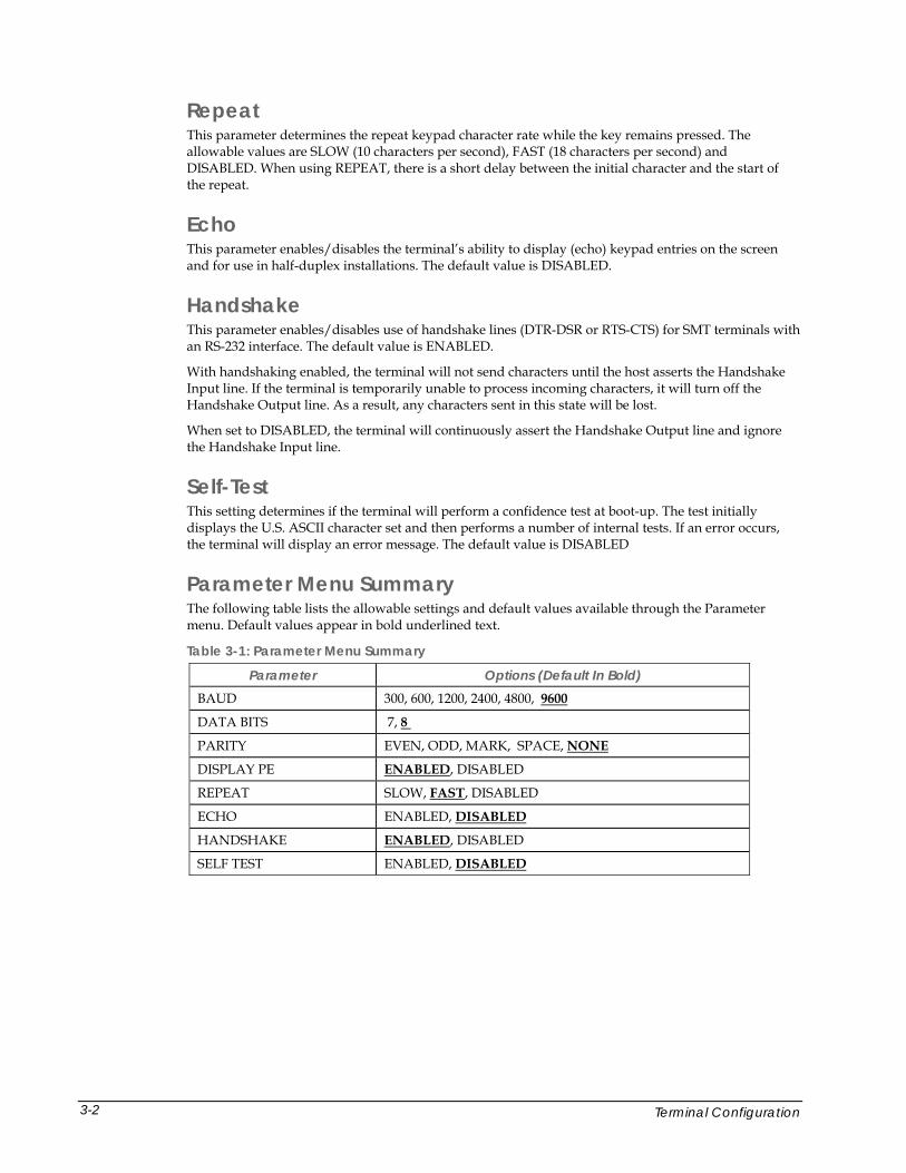
Parameter Menu Summary The following table lists the allowable settings and default values available through the Parameter menu. Default values appear in bold underlined text.
Table 3-1: Parameter Menu Summary
Parameter Options (Default In Bold) BAUD 300, 600, 1200, 2400, 4800, 9600
DATA BITS 7, 8
PARITY EVEN, ODD, MARK, SPACE, NONE
DISPLAY PE ENABLED, DISABLED
REPEAT SLOW, FAST, DISABLED
ECHO ENABLED, DISABLED
HANDSHAKE ENABLED, DISABLED
SELF TEST ENABLED, DISABLED
Terminal Configuration 3-2
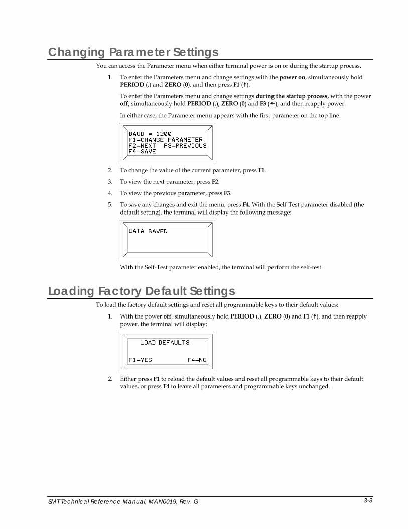
Changing Parameter Settings You can access the Parameter menu when either terminal power is on or during the startup process.
1. To enter the Parameters menu and change settings with the power on, simultaneously hold PERIOD (.) and ZERO (0), and then press F1 ( ).
To enter the Parameters menu and change settings during the startup process, with the power off, simultaneously hold PERIOD (.), ZERO (0) and F3 ( ), and then reapply power.
In either case, the Parameter menu appears with the first parameter on the top line.
2. To change the value of the current parameter, press F1.
3. To view the next parameter, press F2.
4. To view the previous parameter, press F3.
5. To save any changes and exit the menu, press F4. With the Self-Test parameter disabled (the default setting), the terminal will display the following message:
With the Self-Test parameter enabled, the terminal will perform the self-test.
Loading Factory Default Settings To load the factory default settings and reset all programmable keys to their default values:
1. With the power off, simultaneously hold PERIOD (.), ZERO (0) and F1 ( ), and then reapply power. the terminal will display:
2. Either press F1 to reload the default values and reset all programmable keys to their default
values, or press F4 to leave all parameters and programmable keys unchanged.
SMT Technical Reference Manual, MAN0019, Rev. G 3-3
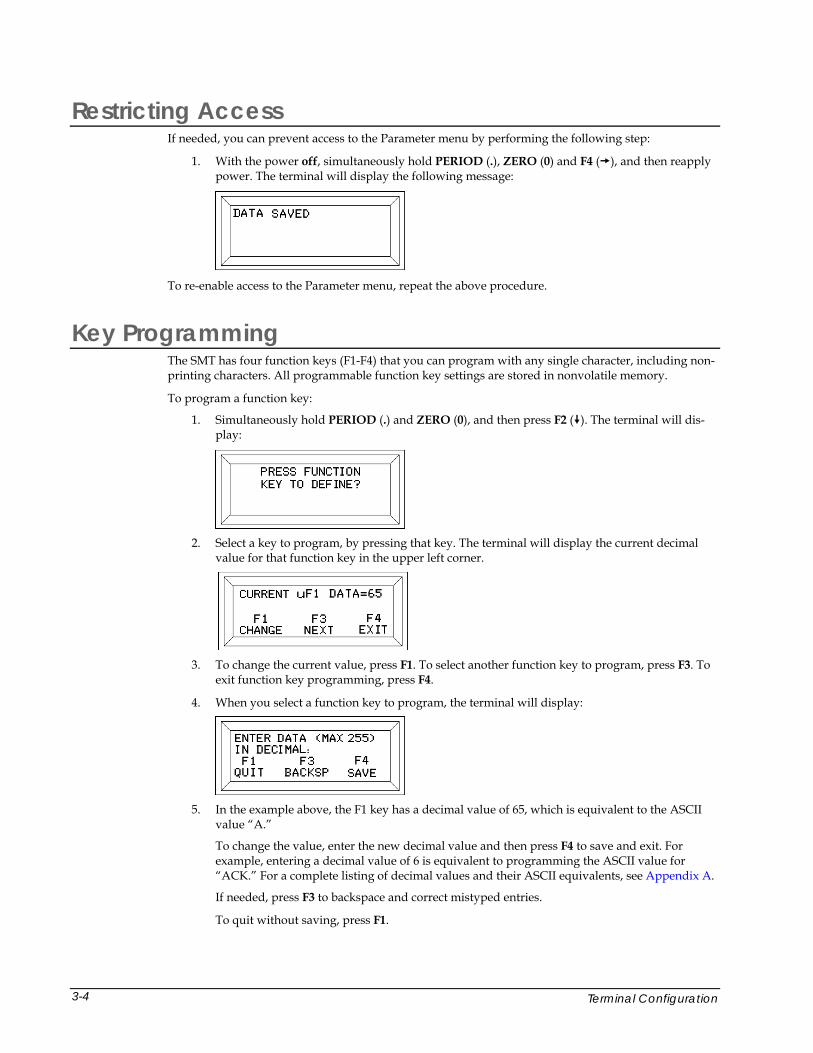
Restricting Access If needed, you can prevent access to the Parameter menu by performing the following step:
1. With the power off, simultaneously hold PERIOD (.), ZERO (0) and F4 ( ), and then reapply power. The terminal will display the following message:
To re-enable access to the Parameter menu, repeat the above procedure.
Key Programming The SMT has four function keys (F1-F4) that you can program with any single character, including non-printing characters. All programmable function key settings are stored in nonvolatile memory.
To program a function key:
1. Simultaneously hold PERIOD (.) and ZERO (0), and then press F2 ( ). The terminal will dis-play:
2. Select a key to program, by pressing that key. The terminal will display the current decimal
value for that function key in the upper left corner.
3. To change the current value, press F1. To select another function key to program, press F3. To
exit function key programming, press F4.
4. When you select a function key to program, the terminal will display:
5. In the example above, the F1 key has a decimal value of 65, which is equivalent to the ASCII
value “A.”
To change the value, enter the new decimal value and then press F4 to save and exit. For example, entering a decimal value of 6 is equivalent to programming the ASCII value for “ACK.” For a complete listing of decimal values and their ASCII equivalents, see Appendix A.
If needed, press F3 to backspace and correct mistyped entries.
To quit without saving, press F1.
Terminal Configuration 3-4

SMT Technical Reference Manual, MAN0019, Rev. G
Chapter 4: Host Commands
Introduction As discussed previously, the SMT terminal’s design allows a host to control its functions by sending commands that begin with the Escape character. For example, sending a Hex 1B 48 (Esc H) will move the cursor to the home position (upper right corner). A command summary appears at the end of this section.
Note: Do not use spaces between characters in Escape commands. Any spacing shown for Escape commands in this chapter is for clarity only unless otherwise noted.
Escape Commands Cursor Up Syntax Esc A
Notes This command moves the cursor up one position. The cursor will not move beyond the start or end of a line, nor will it scroll the display.
Cursor Down Syntax Esc B
Notes This command moves the cursor down one position. The cursor will not move beyond the start or end of a line, nor will it scroll the display.
Cursor Right Syntax Esc C
Notes This command moves the cursor one position to the right. The cursor will not move beyond the start or end of a line, nor will it scroll the display.
Cursor Left Syntax Esc D
Notes This command moves the cursor one position to the right. The cursor will not move beyond the start or end of a line, nor will it scroll the display.
Cursor Home & Clear Display Syntax Esc E
4-1

Enable Underscore Cursor Syntax Esc F
Notes This command is not available on terminals with VFD displays.
Disable Underscore Cursor Syntax Esc G
Notes This command is not available on terminals with VFD displays.
Cursor Home Syntax Esc H
Clear Display Syntax Esc I
Erase Cursor to End of Display Syntax Esc J
Notes Includes the character at the cursor location and does not alter the cursor position
Erase Cursor to End of Line Syntax Esc K
Notes Includes the character at the cursor location and does not alter the cursor position
Sound Long Bell Syntax Esc L
Notes This command requires use of an 8-ohm external speaker connected to the terminal. You cannot buffer sound commands. To produce properly spaced chain sounds, the host must delay a short time between issuing sound commands.
Erase Line Containing Cursor Syntax Esc M
Notes Includes the character at the cursor location and does not alter the cursor position
Sound Click Syntax Esc P
Notes This command requires use of an 8-ohm external speaker connected to the terminal.
Sound Alert Syntax Esc Q
Notes This command requires use of an 8-ohm external speaker connected to the terminal. You cannot buffer sound commands. To produce properly spaced chain sounds, the host must delay a short time between issuing sound commands.
Enable Blinking Cursor Syntax Esc R
Host Commands 4-2
Disable Blinking Cursor Syntax Esc S
Sound Short Bell Syntax Esc T
Notes This command requires use of an 8-ohm external speaker connected to the terminal. You cannot buffer sound commands. To produce properly spaced chain sounds, the host must delay a short time between issuing sound commands.
Enable Key Click Syntax Esc U
Notes This command requires use of an 8-ohm external speaker connected to the terminal.
Disable Key Click Syntax Esc V
Notes This command requires use of an 8-ohm external speaker connected to the terminal
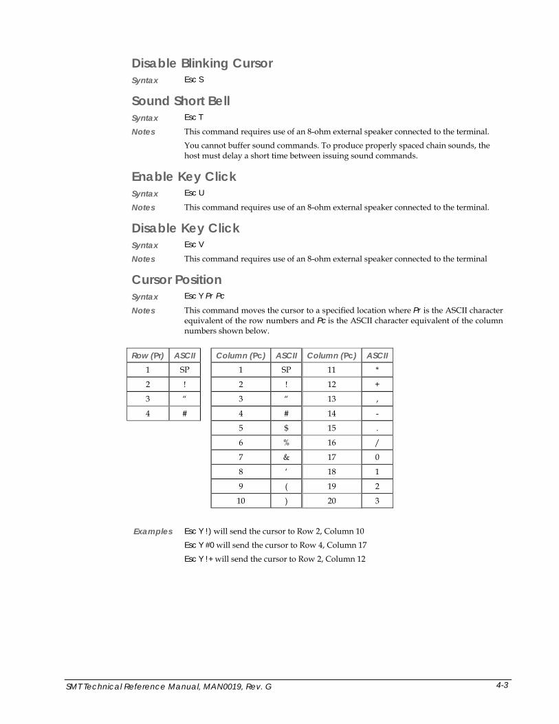
Cursor Position Syntax Esc Y Pr Pc
Notes This command moves the cursor to a specified location where Pr is the ASCII character equivalent of the row numbers and Pc is the ASCII character equivalent of the column numbers shown below.
Row (Pr) ASCII Column (Pc) ASCII Column (Pc) ASCII
1 SP 1 SP 11 *
2 ! 2 ! 12 +
3 “ 3 “ 13 ,
4 # 4 # 14 -
5 $ 15 .
6 % 16 /
7 & 17 0
8 ‘ 18 1
9 ( 19 2
10 ) 20 3
Examples Esc Y !) will send the cursor to Row 2, Column 10
Esc Y #0 will send the cursor to Row 4, Column 17
Esc Y !+ will send the cursor to Row 2, Column 12
SMT Technical Reference Manual, MAN0019, Rev. G 4-3
Send Terminal ID Syntax Esc Z
Notes This command sends a four-byte hexadecimal checksum of the terminal’s program memory, preceded by “SMT.”
When using this command to identify the terminal type, do not include the checksum as it may change.
Enable Backlight Syntax Esc f
Notes This command is only available for use on terminals with a backlit display.
Disable Backlight Syntax Esc n
Notes This command is only available for use on terminals with a backlit display.
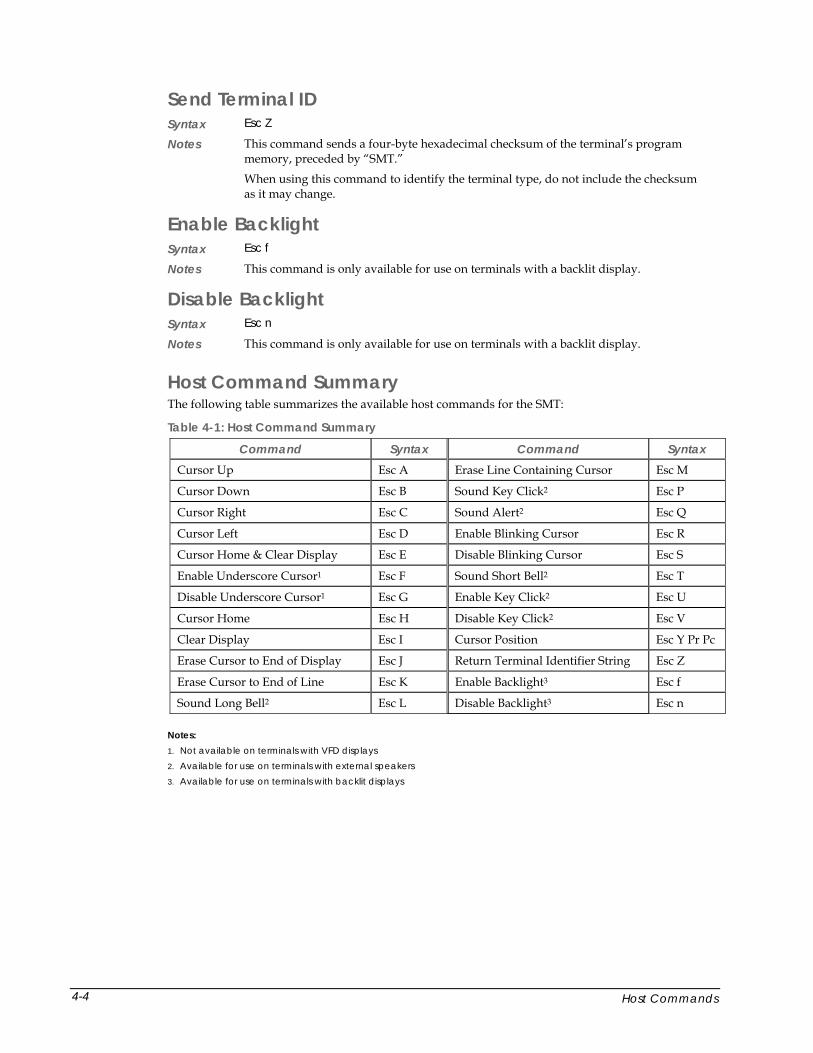
Host Command Summary The following table summarizes the available host commands for the SMT:
Table 4-1: Host Command Summary
Command Syntax Command Syntax Cursor Up Esc A Erase Line Containing Cursor Esc M
Cursor Down Esc B Sound Key Click2 Esc P
Cursor Right Esc C Sound Alert2 Esc Q
Cursor Left Esc D Enable Blinking Cursor Esc R
Cursor Home & Clear Display Esc E Disable Blinking Cursor Esc S
Enable Underscore Cursor1 Esc F Sound Short Bell2 Esc T
Disable Underscore Cursor1 Esc G Enable Key Click2 Esc U
Cursor Home Esc H Disable Key Click2 Esc V
Clear Display Esc I Cursor Position Esc Y Pr Pc
Erase Cursor to End of Display Esc J Return Terminal Identifier String Esc Z
Erase Cursor to End of Line Esc K Enable Backlight3 Esc f
Sound Long Bell2 Esc L Disable Backlight3 Esc n Notes: 1. Not available on terminals with VFD displays 2. Available for use on terminals with external speakers 3. Available for use on terminals with backlit displays
Host Commands 4-4
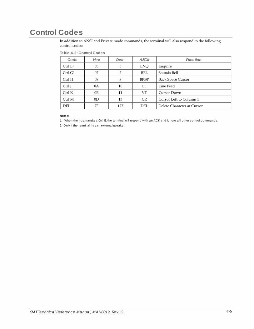
Control Codes In addition to ANSI and Private mode commands, the terminal will also respond to the following control codes:
Table 4-2: Control Codes
Code Hex Dec. ASCII Function Ctrl E1 05 5 ENQ Enquire
Ctrl G2 07 7 BEL Sounds Bell
Ctrl H 08 8 BKSP Back Space Cursor
Ctrl J 0A 10 LF Line Feed
Ctrl K 0B 11 VT Cursor Down
Ctrl M 0D 13 CR Cursor Left to Column 1
DEL 7F 127 DEL Delete Character at Cursor Notes: 1. When the host transits a Ctrl E, the terminal will respond with an ACK and ignore al l other control commands.
2. Only if the terminal has an external speaker.
SMT Technical Reference Manual, MAN0019, Rev. G 4-5


SMT Technical Reference Manual, MAN0019, Rev. G
Chapter 5: Mounting the SMT
Introduction You can mount the SMT permanently or as a detachable unit.
Mounting Configurations Permanent Mounting
• Closed Back Flush—this method enables you to mount the face of the SMT in the front of a panel with the rear cover attached behind the panel. For panel thicknesses between 0.062 and 0.125 inches. For thicker panel walls, contact Two Technologies.
• Permanent Open Back Flush—this method enables you to mount the face of the SMT in the front of a panel with out the rear cover attached behind the panel. For panel thicknesses up to 0.062 inches only. For thicker panel walls, contact Two Technologies. Requires Two Technologies #12285 mounting clamps (provided with unit).
Detachable Mounting • Detachable—this method enables you to attach the unit horizontally or vertically to a panel
with the ability to lift up or slide out the unit from the panel to use as a hand-held terminal.
Permanent Mounting Mounting Kit Each SMT shipped from Two Technologies includes a mounting kit (Figure 5-1). This mounting kit includes the following hardware:
Table 5-1: Mounting Kit
Item # Part Number Description Quantity 1 12288 Gasket 1
2 12285 Mounting Clamps (Plastic) 8
3 12311 Screws, Plastite - #1-32 X 1/2“ Long (Gold) 8
4 12269 Screws, Plastite - #1-32 X 3/8” Long (Silver) 8
5-1
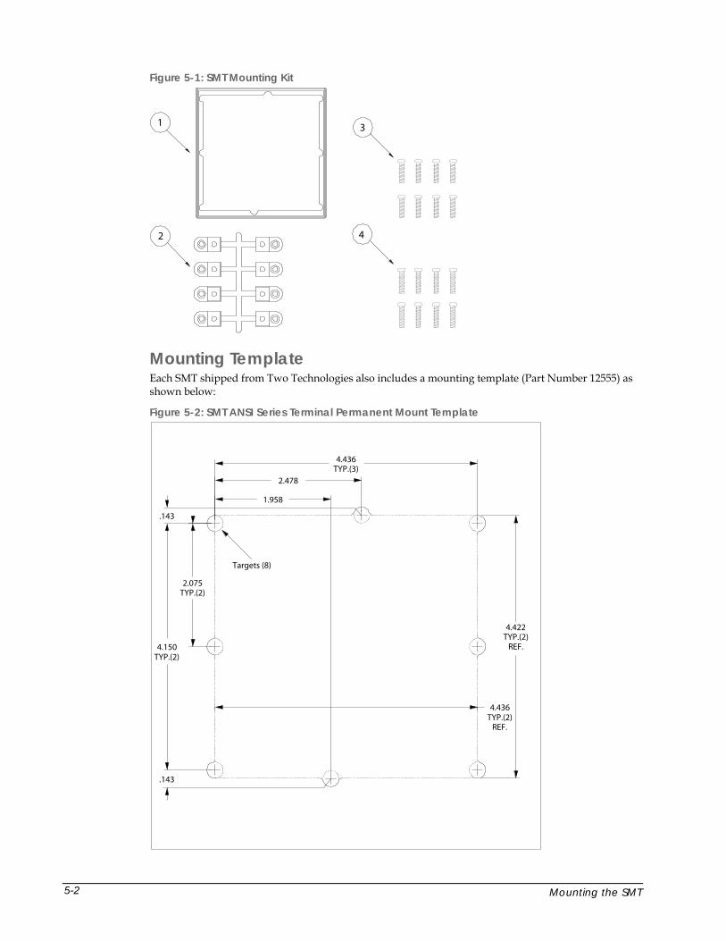
Figure 5-1: SMT Mounting Kit
1 3
2 4
Mounting Template Each SMT shipped from Two Technologies also includes a mounting template (Part Number 12555) as shown below:
Figure 5-2: SMT ANSI Series Terminal Permanent Mount Template
1.958
2.478
4.436TYP.(3)
2.075TYP.(2)
4.150TYP.(2)
.143
.143
4.422TYP.(2)
REF.
4.436TYP.(2)
REF.
Targets (8)
Mounting the SMT 5-2
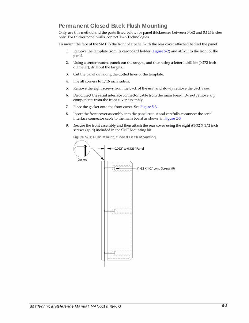
Permanent Closed Back Flush Mounting Only use this method and the parts listed below for panel thicknesses between 0.062 and 0.125 inches only. For thicker panel walls, contact Two Technologies.
To mount the face of the SMT in the front of a panel with the rear cover attached behind the panel.
1. Remove the template from its cardboard holder (Figure 5-2) and affix it to the front of the panel.
2. Using a center punch, punch out the targets, and then using a letter I drill bit (0.272-inch diameter), drill out the targets.
3. Cut the panel out along the dotted lines of the template.
4. File all corners to 1/16 inch radius.
5. Remove the eight screws from the back of the unit and slowly remove the back case.
6. Disconnect the serial interface connector cable from the main board. Do not remove any components from the front cover assembly.
7. Place the gasket onto the front cover. See Figure 5-3.
8. Insert the front cover assembly into the panel cutout and carefully reconnect the serial interface connector cable to the main board as shown in Figure 2-3.
9. .Secure the front assembly and then attach the rear cover using the eight #1-32 X 1/2 inch screws (gold) included in the SMT Mounting kit.
Figure 5-3: Flush Mount, Closed Back Mounting
0.062" to 0.125" Panel
Gasket
#1-32 X 1/2" Long Screws (8)
SMT Technical Reference Manual, MAN0019, Rev. G 5-3
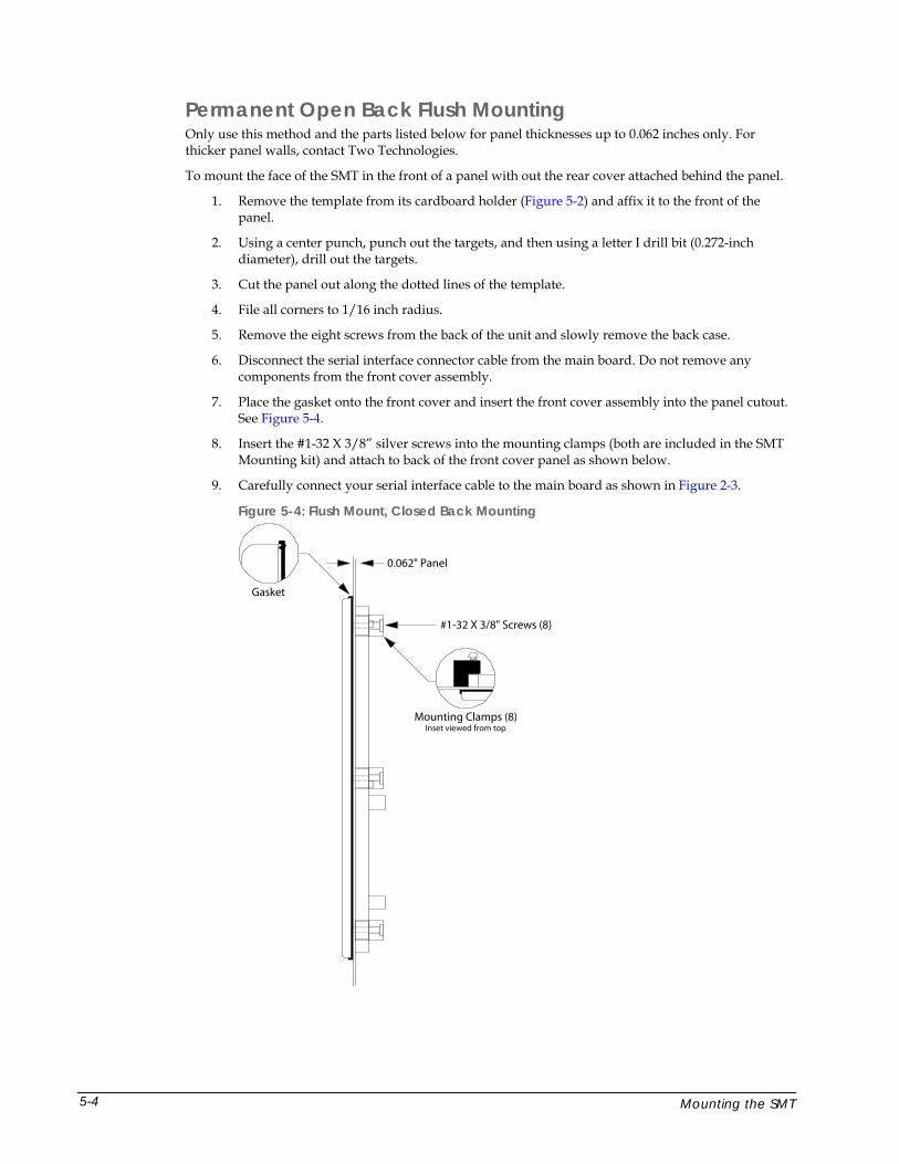
Permanent Open Back Flush Mounting Only use this method and the parts listed below for panel thicknesses up to 0.062 inches only. For thicker panel walls, contact Two Technologies.
To mount the face of the SMT in the front of a panel with out the rear cover attached behind the panel.
1. Remove the template from its cardboard holder (Figure 5-2) and affix it to the front of the panel.
2. Using a center punch, punch out the targets, and then using a letter I drill bit (0.272-inch diameter), drill out the targets.
3. Cut the panel out along the dotted lines of the template.
4. File all corners to 1/16 inch radius.
5. Remove the eight screws from the back of the unit and slowly remove the back case.
6. Disconnect the serial interface connector cable from the main board. Do not remove any components from the front cover assembly.
7. Place the gasket onto the front cover and insert the front cover assembly into the panel cutout. See Figure 5-4.
8. Insert the #1-32 X 3/8” silver screws into the mounting clamps (both are included in the SMT Mounting kit) and attach to back of the front cover panel as shown below.
9. Carefully connect your serial interface cable to the main board as shown in Figure 2-3.
Figure 5-4: Flush Mount, Closed Back Mounting
Mounting Clamps (8)Inset viewed from top
0.062" Panel
Gasket
#1-32 X 3/8" Screws (8)
Mounting the SMT 5-4
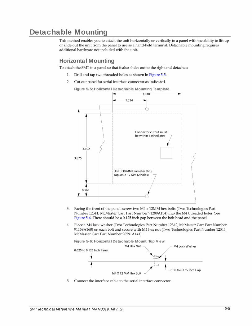
Detachable Mounting This method enables you to attach the unit horizontally or vertically to a panel with the ability to lift up or slide out the unit from the panel to use as a hand-held terminal. Detachable mounting requires additional hardware not included with the unit.
Horizontal Mounting To attach the SMT to a panel so that it also slides out to the right and detaches:
1. Drill and tap two threaded holes as shown in Figure 5-5.
2. Cut out panel for serial interface connector as indicated.
Figure 5-5: Horizontal Detachable Mounting Template
0.568
3.875
3.102
3.048
1.524
Connector cutout mustbe within dashed area
Drill 3.30 MM Diameter thru,Tap M4 X 12 MM (2 holes)
3. Facing the front of the panel, screw two M4 x 12MM hex bolts (Two Technologies Part
Number 12341, McMaster Carr Part Number 91280A134) into the M4 threaded holes. See Figure 5-6. There should be a 0.125 inch gap between the bolt head and the panel
4. Place a M4 lock washer (Two Technologies Part Number 12342, McMaster Carr Part Number 91169A160) on each bolt and secure with M4 hex nut (Two Technologies Part Number 12343, McMaster Carr Part Number 90591A141).
Figure 5-6: Horizontal Detachable Mount, Top View
M4 X 12 MM Hex Bolt
0.625 to 0.125 Inch PanelM4 Hex Nut
0.130 to 0.135 Inch Gap
M4 Lock Washer
5. Connect the interface cable to the serial interface connector.
SMT Technical Reference Manual, MAN0019, Rev. G 5-5

6. Place the unit onto the mounting bolts and then slide the unit left to secure. See Figure 5-7.
Figure 5-7: Horizontal Detachable Mount, Front View
Vertical Mounting To attach the SMT to a panel so that it also lifts up and detaches:
1. Drill and tap two threaded holes as shown in Figure 5-8.
2. Cut out panel for serial interface connector as indicated.
Figure 5-8: Vertical Detachable Mounting Template
3.875
0.423
3.102
1.565
3.048
Connector cutout mustbe within dashed area
Drill 3.30 MM Diameter thru,Tap M4 X 12 MM (2 holes)
Mounting the SMT 5-6
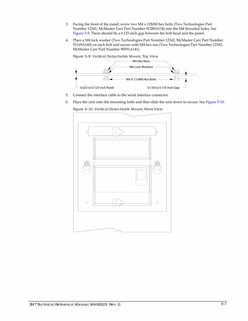
3. Facing the front of the panel, screw two M4 x 12MM hex bolts (Two Technologies Part Number 12341, McMaster Carr Part Number 91280A134) into the M4 threaded holes. See Figure 5-9. There should be a 0.125-inch gap between the bolt head and the panel.
4. Place a M4 lock washer (Two Technologies Part Number 12342, McMaster Carr Part Number 91169A160) on each bolt and secure with M4 hex nut (Two Technologies Part Number 12343, McMaster Carr Part Number 90591A141).
Figure 5-9: Vertical Detachable Mount, Top View
M4 X 12 MM Hex Bolts
0.625 to 0.125 Inch Panel
M4 Hex Nuts
0.130 to 0.135 Inch Gap
M4 Lock Washers
5. Connect the interface cable to the serial interface connector.
6. Place the unit onto the mounting bolts and then slide the unit down to secure. See Figure 5-10.
Figure 5-10: Vertical Detachable Mount, Front View
SMT Technical Reference Manual, MAN0019, Rev. G 5-7

SMT Technical Reference Manual, MAN0019, Rev. G
Chapter 6: Troubleshooting
Cursor does not appear on display Possible Cause: No power to terminal (host supplied)
Solution: Verify proper voltage to terminal
Possible Cause: No power to terminal (adapter supplied)
Solution: Verify wall plug is functional and wiring of adapter (if wired as kit)
Possible Cause: Reversed polarity, improper wiring or wrong cable type
Solution: Check cable and connector wiring
Possible Cause: Cursor not enabled
Solution: Re-enable the cursor by sending an Esc R
Terminal resets or locks-up Possible Cause: Low voltage output
Solution: Verify proper voltage to terminal
Possible Cause: Cable resistance too high or wire gauge too small
Solution: Cable should be 26 AWG or larger
Possible Cause: Handshaking between host and terminal
Solution: When using handshaking, verify that the wiring between the host and terminal is correct, that you have the HANDSHAKE parameter enabled and that the handshake line from the host is asserted When not using handshaking, make sure you have the HANDSHAKE parameter disabled
Possible Cause: Internal IO connection improperly connected
Solution: Reconnect properly (see Figure 2-3)
Terminal displays double characters Possible Cause: Echo turned on
Solution: Disable ECHO parameter
6-1
Terminal does not perform self-test Possible Cause: Self-test parameter disabled
Solution: Change SELF TEST parameter to ENABLE
Terminal not receiving or displaying correct characters Possible Cause: Parity settings incorrect
Solution: Change PARITY parameter to correct setting
Possible Cause: Data bits incorrect
Solution: Change DATA BITS parameter to correct setting
Possible Cause: Incorrect BAUD rate
Solution: Change BAUD parameter to correct setting
Possible Cause: Handshaking between host and terminal
Solution: When using handshaking, verify that the wiring between the host and terminal is correct, that you have the HANDSHAKE parameter enabled and that the handshake line from the host is asserted
When not using handshaking, make sure you have the HANDSHAKE parameter disabled
Possible Cause: Reversed polarity, improper wiring or wrong cable type
Solution: Check cable and connector wiring
Terminal displays PE character Possible Cause: Incorrect parity setting
Solution: Change the PARITY setting on the terminal to match the host or vice versa
Possible Cause: Handshaking between host and terminal
Solution: When using handshaking, verify that the wiring between the host and terminal is correct, that you have the HANDSHAKE parameter enabled and that the handshake line from the host is asserted
When not using handshaking, make sure you have the HANDSHAKE parameter disabled
Terminal generates continuous sound while pressing key Possible Cause: Handshaking between host and terminal
Solution: When using handshaking, verify that the wiring between the host and terminal is correct, that you have the HANDSHAKE parameter enabled and that the handshake line from the host is asserted When not using handshaking, make sure you have the HANDSHAKE parameter disabled
Troubleshooting 6-2

Key does not repeat when pressed Possible Cause: Repeat parameter disabled
Solution: Change repeat parameter to either SLOW or FAST
Cannot access parameter mode or function key programming Possible Cause: Menu lock-out enabled
Solution: Remove power, simultaneously hold PERIOD (.), ZERO (0) and F4, and then reapply power
Possible Cause: Handshaking between host and terminal
Solution:
When using handshaking, verify that the wiring between the host and terminal is correct, that you have the HANDSHAKE parameter enabled and that the handshake line from the host is asserted
When not using handshaking, make sure you have the HANDSHAKE parameter disabled
Possible Cause: Internal IO connection improperly connected
Terminal losing characters Possible Cause: Handshaking between host and terminal
Solution:
When using handshaking, verify that the wiring between the host and terminal is correct, that you have the HANDSHAKE parameter enabled and that the handshake line from the host is asserted
When not using handshaking, make sure you have the HANDSHAKE parameter disabled
Function keys not sending correct values Possible Cause: Key accidentally reprogrammed
Solution: Reprogram function key
Possible Cause: EEPROM corrupted by line disturbance
Solution: Restore factory defaults and then reprogram parameters and function keys
Possible Cause: Terminal reset to factory defaults after repair
Solution: Reprogram function keys
SMT Technical Reference Manual, MAN0019, Rev. G 6-3

SMT Technical Reference Manual, MAN0019, Rev. G
Appendix A: Specifications
Display Reflective/Transreflective Liquid Crystal Display
4 Row x 20 Character Display Format Standard Character Set: US ASCII (5 x 7 pixels). Latin1 and European Character Sets also
available
Dark Characters on Light Background (except VFD) Optional Supertwist, Supertwist Backlit, Extended Temperature Supertwist Backlit, VFD and
Extended Temperature VFD available
Keys & Switches Type: Membrane or Elastomeric
Standard Layouts: 20-key
Feedback: Tactile and Audible
Four Programmable: Function Keys
Optional Backlit and Backlit Phosphorescent Keypads available
Power Voltage: 5 VDC +/- 5%, 7.5-12 VDC* Linear Regulator or 9.5-28 VDC Switching Regulator
Current: 45-50 mA typical (some options will require additional current) *Maximum voltage depends on current draw.
Interface Type: RS-232, RS-422 or CMOS/LSTTL level
Handshaking: 2 Lines (DTR, DTS) for RS-232, CMOS/LSTTL
Data Rates: 110 to 9,600
Parity Range: Even, Odd, Mark, Space and None
Control Bits: 1 Start and 1-2 Stop Bits
Standard Interface Connector: 6 Pin Female Modular Connector
Environmental Nematic Displays
Storage Temperature: -20°C to +70°C,
Operating Temperature: Standard: 0° to + 50°C, Extended Temperature: -20°C to +70°C
Vacuum Fluorescent Displays
Storage Temperature: -40° to + 85°C
Operating Temperature: Standard: -20° to + 70°C, Extended Temperature: -40° to + 85°C
Humidity: 5-95% (Non-condensing)Humidity: 5-95% (non-condensing)
A-1
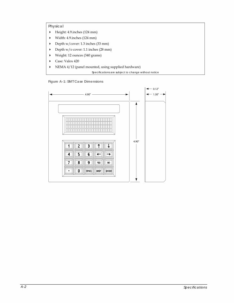
Physical Height: 4.9.inches (124 mm)
Width: 4.9.inches (124 mm)
Depth w/cover: 1.3 inches (33 mm)
Depth w/o cover: 1.1 inches (28 mm)
Weight: 12 ounces (340 grams)
Case: Valox 420
NEMA 4/12 (panel mounted, using supplied hardware) Specifications are subject to change without notice
Figure A-1: SMT Case Dimensions
4.90"
4.90"
1.30"
0.12"
F4F3
F2
Specifications A-2
SMT Technical Reference Manual, MAN0019, Rev. G
Appendix B: ASCII Character Set
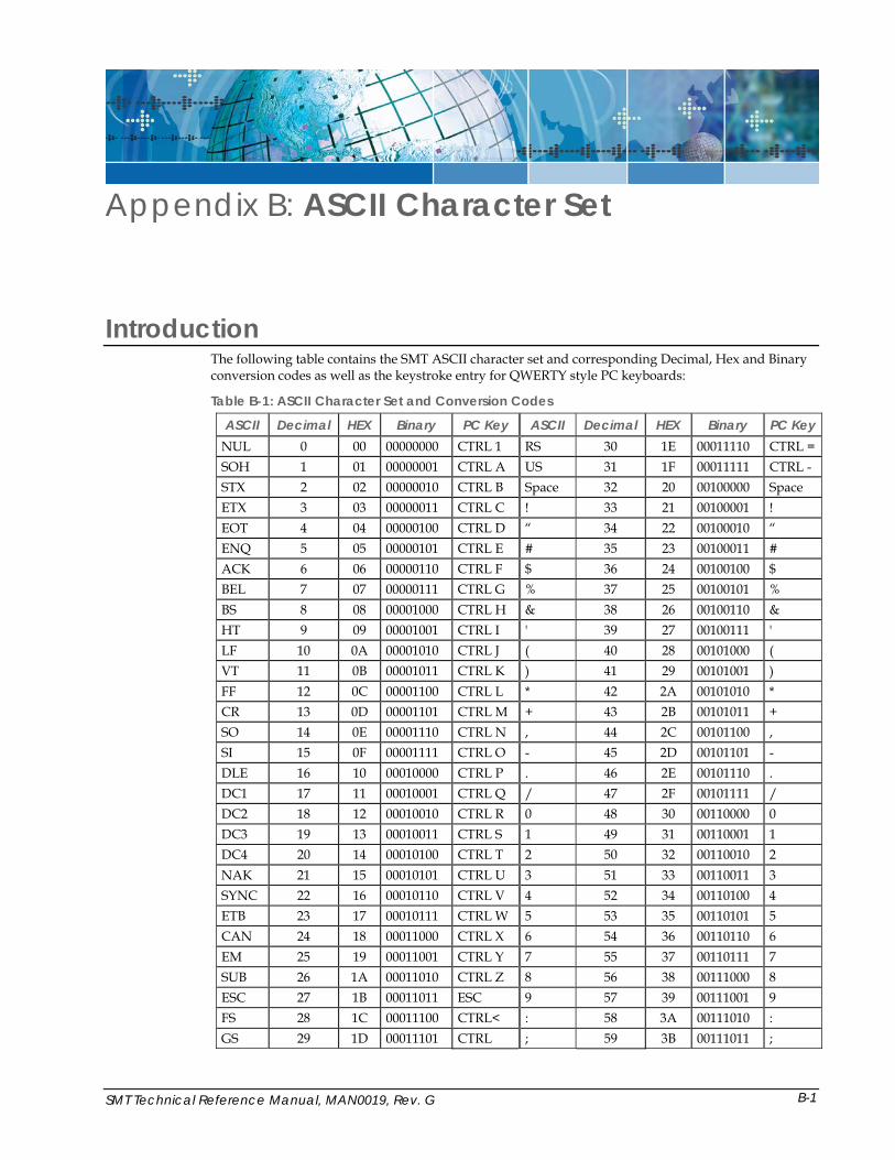
Introduction The following table contains the SMT ASCII character set and corresponding Decimal, Hex and Binary conversion codes as well as the keystroke entry for QWERTY style PC keyboards:
Table B-1: ASCII Character Set and Conversion Codes
ASCII Decimal HEX Binary PC Key ASCII Decimal HEX Binary PC Key NUL 0 00 00000000 CTRL 1 RS 30 1E 00011110 CTRL = SOH 1 01 00000001 CTRL A US 31 1F 00011111 CTRL - STX 2 02 00000010 CTRL B Space 32 20 00100000 Space ETX 3 03 00000011 CTRL C ! 33 21 00100001 ! EOT 4 04 00000100 CTRL D “ 34 22 00100010 “ ENQ 5 05 00000101 CTRL E # 35 23 00100011 # ACK 6 06 00000110 CTRL F $ 36 24 00100100 $ BEL 7 07 00000111 CTRL G % 37 25 00100101 % BS 8 08 00001000 CTRL H & 38 26 00100110 & HT 9 09 00001001 CTRL I ' 39 27 00100111 ' LF 10 0A 00001010 CTRL J ( 40 28 00101000 ( VT 11 0B 00001011 CTRL K ) 41 29 00101001 ) FF 12 0C 00001100 CTRL L * 42 2A 00101010 * CR 13 0D 00001101 CTRL M + 43 2B 00101011 + SO 14 0E 00001110 CTRL N , 44 2C 00101100 , SI 15 0F 00001111 CTRL O - 45 2D 00101101 - DLE 16 10 00010000 CTRL P . 46 2E 00101110 . DC1 17 11 00010001 CTRL Q / 47 2F 00101111 / DC2 18 12 00010010 CTRL R 0 48 30 00110000 0 DC3 19 13 00010011 CTRL S 1 49 31 00110001 1 DC4 20 14 00010100 CTRL T 2 50 32 00110010 2 NAK 21 15 00010101 CTRL U 3 51 33 00110011 3 SYNC 22 16 00010110 CTRL V 4 52 34 00110100 4 ETB 23 17 00010111 CTRL W 5 53 35 00110101 5 CAN 24 18 00011000 CTRL X 6 54 36 00110110 6 EM 25 19 00011001 CTRL Y 7 55 37 00110111 7 SUB 26 1A 00011010 CTRL Z 8 56 38 00111000 8 ESC 27 1B 00011011 ESC 9 57 39 00111001 9 FS 28 1C 00011100 CTRL< : 58 3A 00111010 : GS 29 1D 00011101 CTRL ; 59 3B 00111011 ;
B-1
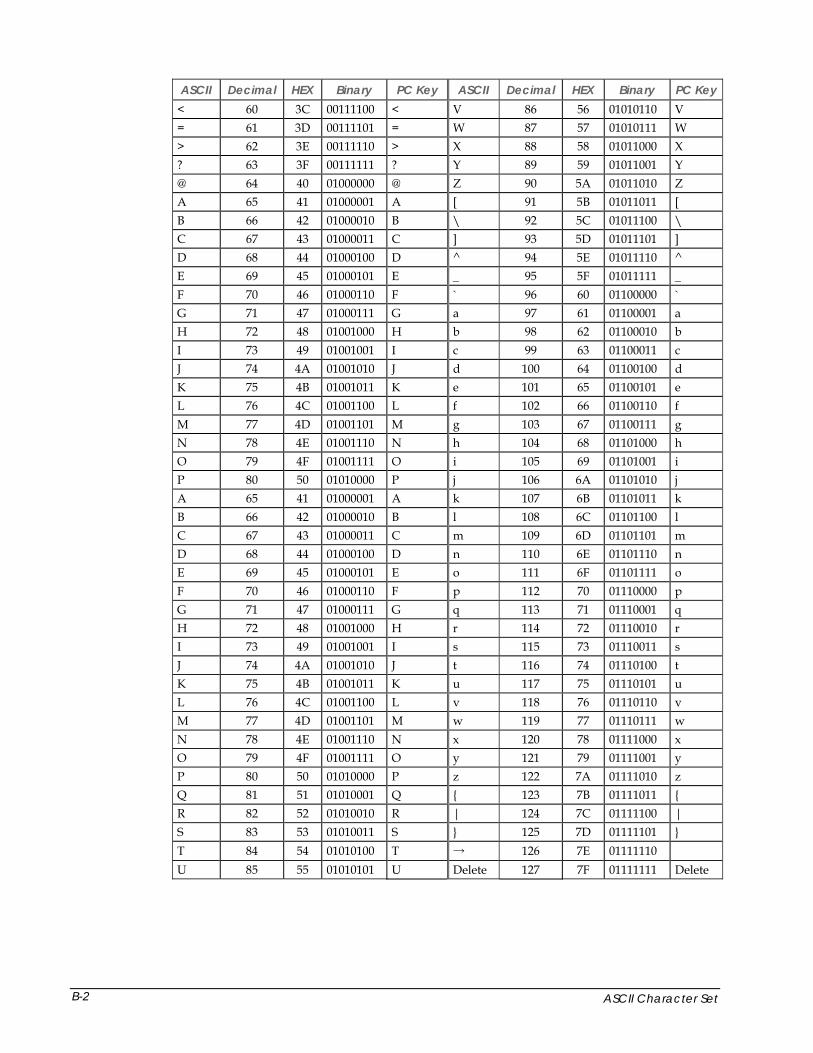
ASCII Decimal HEX Binary PC Key ASCII Decimal HEX Binary PC Key < 60 3C 00111100 < V 86 56 01010110 V = 61 3D 00111101 = W 87 57 01010111 W > 62 3E 00111110 > X 88 58 01011000 X ? 63 3F 00111111 ? Y 89 59 01011001 Y @ 64 40 01000000 @ Z 90 5A 01011010 Z A 65 41 01000001 A [ 91 5B 01011011 [ B 66 42 01000010 B \ 92 5C 01011100 \ C 67 43 01000011 C ] 93 5D 01011101 ] D 68 44 01000100 D ^ 94 5E 01011110 ^ E 69 45 01000101 E _ 95 5F 01011111 _ F 70 46 01000110 F ` 96 60 01100000 ` G 71 47 01000111 G a 97 61 01100001 a H 72 48 01001000 H b 98 62 01100010 b I 73 49 01001001 I c 99 63 01100011 c J 74 4A 01001010 J d 100 64 01100100 d K 75 4B 01001011 K e 101 65 01100101 e L 76 4C 01001100 L f 102 66 01100110 f M 77 4D 01001101 M g 103 67 01100111 g N 78 4E 01001110 N h 104 68 01101000 h O 79 4F 01001111 O i 105 69 01101001 i P 80 50 01010000 P j 106 6A 01101010 j A 65 41 01000001 A k 107 6B 01101011 k B 66 42 01000010 B l 108 6C 01101100 l C 67 43 01000011 C m 109 6D 01101101 m D 68 44 01000100 D n 110 6E 01101110 n E 69 45 01000101 E o 111 6F 01101111 o F 70 46 01000110 F p 112 70 01110000 p G 71 47 01000111 G q 113 71 01110001 q H 72 48 01001000 H r 114 72 01110010 r I 73 49 01001001 I s 115 73 01110011 s J 74 4A 01001010 J t 116 74 01110100 t K 75 4B 01001011 K u 117 75 01110101 u L 76 4C 01001100 L v 118 76 01110110 v M 77 4D 01001101 M w 119 77 01110111 w N 78 4E 01001110 N x 120 78 01111000 x O 79 4F 01001111 O y 121 79 01111001 y P 80 50 01010000 P z 122 7A 01111010 z Q 81 51 01010001 Q { 123 7B 01111011 { R 82 52 01010010 R | 124 7C 01111100 | S 83 53 01010011 S } 125 7D 01111101 } T 84 54 01010100 T → 126 7E 01111110 U 85 55 01010101 U Delete 127 7F 01111111 Delete
ASCII Character Set B-2
SMT Technical Reference Manual, MAN0019, Rev. G
Index
1 1210-15 Cable.....................................................................2-5 1210-15NR Cable...............................................................2-5 1210-7 Cable.......................................................................2-5 1210-7NR Cable.................................................................2-5
A About the SMT ..................................................................1-2 About this Manual ............................................................1-1 About Two Technologies .................................................1-1 ASCII Character Set ......................................................... B-1
B Baud Rate ...........................................................................3-1
C Cable and Power Connections ........................................2-2 Cable Connections ............................................................2-6 Case Dimensions............................................................. A-2 Changing Parameter Settings..........................................3-3 Clear Display .....................................................................4-2 CMOS .................................................................................2-4 Connecting the Terminal .................................................2-5 Control Codes....................................................................4-5 Controls and Indicators....................................................2-1 Current Draw .................................................................... vii Cursor Down .....................................................................4-1 Cursor Home .....................................................................4-2 Cursor Home & Clear Display ........................................4-1 Cursor Left .........................................................................4-1 Cursor Position.......................................................... 2-8, 4-3 Cursor Right ......................................................................4-1 Cursor Up ..........................................................................4-1
D Data Bits .............................................................................3-1 Detachable Mounting ............................................... 5-1, 5-5 Disable Backlight ..............................................................4-4 Disable Blinking Cursor ...................................................4-3 Disable Key Click..............................................................4-3 Disable Underscore Cursor..............................................4-2
Display........................................................................1-2, 2-1 Display Header Connections .......................................... 2-2 Display Operation ............................................................ 2-8 Display PE ......................................................................... 3-1 Display Specifications.....................................................A-1 Durability .......................................................................... 1-2
E Echo.................................................................................... 3-2 Enable Backlight ............................................................... 4-4 Enable Blinking Cursor.................................................... 4-2 Enable Key Click............................................................... 4-3 Enable Underscore Cursor .............................................. 4-2 Environmental Specifications ........................................A-1 Erase Cursor to End of Display ...................................... 4-2 Erase Cursor to End of Line ............................................ 4-2 Erase Line Containing Cursor Home............................. 4-2 Escape Commands ........................................................... 4-1 Extended Voltage Header Connections......................... 2-3
F Flush Mount, Closed Back Mounting .....................5-3, 5-4
H Handshake ........................................................................ 3-2 Header Locations.............................................................. 2-2 Horizontal Detachable Mount, Front View................... 5-6 Horizontal Detachable Mount, Top View ..................... 5-5 Horizontal Detachable Mounting Template ................. 5-5 Horizontal Mounting ....................................................... 5-5 Host Command Summary .............................................. 4-4 Host Commands............................................................... 4-1 Host Control...................................................................... 2-8
I I/O Header Connections................................................. 2-2 Interface Options .............................................................. 1-2 Interface Specifications ...................................................A-1 Internal Communication Devices................................... 2-3 Internal Connections........................................................ 2-2
I-1
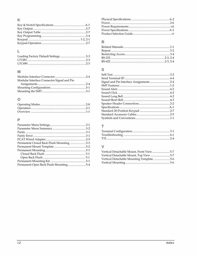
K Key & Switch Specifications ...........................................A-1 Key Output ........................................................................2-7 Key Output Table .............................................................2-7 Key Programming ............................................................3-4 Keypad ....................................................................... 1-2, 2-1 Keypad Operation ............................................................2-7
L Loading Factory Default Settings ...................................3-3 LT1281 ................................................................................2-3 LTC490 ...............................................................................2-3
M Modular Interface Connector ..........................................2-4 Modular Interface Connector Signal and Pin
Assignments..................................................................2-4 Mounting Configurations ................................................5-1 Mounting the SMT............................................................5-1
O Operating Modes ..............................................................2-8 Operation ...........................................................................2-1 Overview ...........................................................................1-1
P Parameter Menu Settings.................................................3-1 Parameter Menu Summary .............................................3-2 Parity ..................................................................................3-1 Parity Error ........................................................................3-1 PCAT Wired Adapter.......................................................2-5 Permanent Closed Back Flush Mounting ......................5-3 Permanent Mount Template ...........................................5-2 Permanent Mounting .......................................................5-1
Closed Back Flush ....................................................... 5-1 Open Back Flush.......................................................... 5-1
Permanent Mounting Kit .................................................5-1 Permanent Open Back Flush Mounting.........................5-4
Physical Specifications....................................................A-2 Power ................................................................................. 2-6 Power Requirements.........................................................vii Power Specifications .......................................................A-1 Product Selection Guide ....................................................vi
R Related Manuals ............................................................... 1-1 Repeat ................................................................................ 3-2 Restricting Access............................................................. 3-4 RS-232 .........................................................................2-3, 2-4 RS-422 .........................................................................2-3, 2-4
S Self-Test ............................................................................. 3-2 Send Terminal ID ............................................................. 4-4 Signal and Pin Interface Assignments ........................... 2-4 SMT Features .................................................................... 1-2 Sound Alert ....................................................................... 4-2 Sound Click ....................................................................... 4-2 Sound Long Bell ............................................................... 4-2 Sound Short Bell ............................................................... 4-3 Speaker Header Connections.......................................... 2-2 Specifications ...................................................................A-1 Standard 20-Position Keypad ......................................... 2-7 Standard Accessory Cables ............................................. 2-5 Symbols and Conventions............................................... 1-1
T Terminal Configuration................................................... 3-1 Troubleshooting ............................................................... 6-1 TTL ..................................................................................... 2-4
V Vertical Detachable Mount, Front View........................ 5-7 Vertical Detachable Mount, Top View .......................... 5-7 Vertical Detachable Mounting Template ...................... 5-6 Vertical Mounting ............................................................ 5-6
Index I-2