Embed Size (px)
Citation preview
SMT-920 Viking Commercial multistage HVAC controller
User & Installer Manual
Ver 2.9

Page 2
Preface The new SMT-920 “Viking” HVAC controller has been built by Smart Temp Australia using the best components and design philosophy currently available. As a result, the Smart Temp SMT-920 “Viking” will provide your clients with many years of trouble free comfort control. It is highly recommended that you take the time to read and understand these simple instructions so that you can take full advantage of the many functions and capabilities that are offered in this premium product. The SMT-920 “Viking” product is under constant revision, upgrade and enhancement to meet the new needs of the market. A table below provides a revision history of the manual – which in most cases reflects product improvement.
Manual Revision History
Ver. 1 First Release.
Ver. 1.01 Some minor spelling and diagram errors corrected.
Ver. 2.0 Version II Hardware. Improved “Smart Sensor” hardware. Added BACnet MS-TP communications. Improved AO functions. Added service Menu. Added Night purge. Removed Modbus point data from manual – (separate communications manual provided).
Ver. 2.5 Removed outside air temperature sensor input. (outside temp only measured with Smart Sensor) Added 0-10V input for IAQ function. Changed economy settings to better support enthalpy control. Compressor call now suspends outside air function. Minor bug fixes and performance enhancements.
Ver. 2.6 Some wording changes in the manual. Small spelling and diagram errors corrected. Stage down for 4 compressor systems improved.
Ver. 2.7 Added hi / low temperature alarm function. Added PI control. Improved DST setting. Fixed night purge bug. Increased holiday events to 30. Other minor enhancements and improvements.
Ver. 2.8 Additional wording and function description corrections. Added support for version II of the Smart sensor with Display.
Ver. 2.9 Fixed bug that can cause loss of Smart sensor communication with change in communications baud rate. Added Humidity Set point, added Hi/Low select function, added communications parity select, added H, C & H&C output on aux relay menu, added basic/advanced mode in installer menu layout, improved AH button logic, improved economy indication, clarified information in the manual.
Great care has been taken in the preparation of this manual. Smart Temp Australia P/L takes no
responsibility for errors or omissions contained in this document. It is the responsibility of the user to ensure this controller or equipment connected to it is operating to their respective
specifications and in a safe manner.
Due to ongoing product improvement Smart Temp Australia P/L reserves the right to change the specifications of the SMT-920 “Viking” (or its components) without notice.
All rights reserved. © Smart Temp Australia P/L 2010.
Intellectual rights apply.

Page 3
Index
Preface....................................................................... 2
Index .......................................................................... 3
Installation ................................................................. 4
Wiring Overview ........................................................ 4 Powering the Viking ................................................... 4 Equipment Connections ............................................ 4 Communications Terminals ....................................... 5 0-10V Outputs ........................................................... 5 0-10V Input ................................................................ 5 Room Sensor Input (2 wire) ....................................... 5 Auxiliary Inputs .......................................................... 5 Setting the 2 DIP Switches Functions ......................... 5 Commissioning Aids ................................................... 6
Info Window .............................................................. 6 Service Override ........................................................ 6 Service Mode ............................................................. 6 Relay Test Mode ........................................................ 6 Economy Test Mode .................................................. 6 Typical Wiring Diagrams ............................................ 6
0-10V Wiring .............................................................. 9
Sensor Wiring ............................................................ 9
Ancillary Input wiring ................................................. 12 Setting Installer Preferences ...................................... 12
Operation .................................................................. 23
The PIN Prompt ......................................................... 23 Setting the “Start” event or run temperatures .......... 23 Programming ............................................................. 23 Setting the Clock ........................................................ 24 Setting Daily Schedules .............................................. 24 Set Holiday Schedules ................................................ 25 Setting Daylight Savings Times .................................. 26 Advanced Features .................................................... 27
Economy Cycle ........................................................... 27
Economy Checklist. .................................................... 28 CO2 input ................................................................... 28 Valve Control ............................................................. 29 After Hours Timer ...................................................... 29 Handover Relay ......................................................... 30 Compressor Lead Lag ................................................. 30 Tips &Tricks ............................................................... 30
Communications Functions ....................................... 33
Faults ......................................................................... 34
Specifications ............................................................. 35

Page 4
Installation
Wiring Overview The Viking is a DIN rail mounted device that has been designed to precisely control a wide selection of HVAC systems in commercial applications. Great effort has been made to ensure the Viking is very simple to set up and install ensuring reliable control of commercial HVAC systems. A brief input / output explanation is provided below, further function specific detail is provided through this manual.
Powering the Viking The Viking can be powered from either 24VAC (+/-15%) or from 100 to 270 VAC. Use one power input only. The A&N input is used for powering the Viking from line voltage (270V max). The terminal marked G is the 24V active terminal; the Go is the 24V common terminal.
Equipment Connections A common input is provided for the main 5 equipment relays while a separate relay common is provided for the 6th, auxiliary relay input. The 6th Auxiliary Function relay has multiple installer selected functions so a separate voltage can be used with this relay if necessary. See page 17 for more information on this relays capabilities. A change over relay is provided for first stage heating and cooling should the Viking need control drive open/drive closed valves. All other relays are single pole normally open. All relays are rated at up to 300V, the Fan relay is rated at 12Amps resistive; all other relays are rated at 5Amps resistive maximum. It is recommended that an external fuse be used to protect the Viking relays or the equipment it is controlling. Do not exceed the maximum current handling capacity of any of the Viking relays.

Page 5
Communications Terminals The Viking is provided with hardware and firmware to provide MODbus RTU communications capability. The “A” and “B” terminals are provided for communications.
The communications terminals “A” and “B” are close to the 24V input.
Take extreme care that 24V is not accidentally applied to the communications terminals or damage to the communications capability of the Viking will result.
0-10V Outputs 2 x 0-10 Volt outputs have been provided. These 0-10V output functions are defined in the installer manual on page 20 of this manual.
0-10V Input 1 x 0-10 Volt input has been provided. This 0-10V input function is defined in the installer manual on page 19.
Room Sensor Input (2 wire) The standard room temperature sensor is wired to the Room and Com (Common) terminal next to it. It is recommended that 0.25mm or larger screened pair cable is used and the screen drain wire earthed in a suitable location. This is especially important where long cable runs are expected (>15M) or where the sensor cable is run close to other electrical cabling. It is recommended to use the 4 wire communicating room sensor if you have concerns about cable runs or interference in the sensor wiring. As this sensor is a digital sensor, screened cable is required on all cable runs with the screen drain wire earthed in a suitable location.
Auxiliary Inputs The Viking has two digital inputs. These inputs have a number of pre-set functions selectable by the installer. A list of available functions for these inputs is provided in the advanced installer options listed on page 19. These inputs are volt free and initiated by switching the auxiliary input to the “COM” (common) terminal next to them. These inputs are VOLT FREE. Do NOT apply any external voltage to these Auxiliary input terminals
or damage to the Viking WILL result. This is NOT covered by warranty.
Setting the 2 DIP Switches Functions There are 2 DIP switches that are used to set core function of the Viking. A table outlining these functions is provided below. These switch functions do not require the Viking to be powered to be set.
Switch Function Off On
1 If Sw 2 = Off HP - Reversing valve logic If Sw2 = On HC - Heat Fan logic
Energise in Heat Electric Heating
Energise in Cool Gas Heating
2 Equipment control logic Heat Pump Heat Cool
Page 6
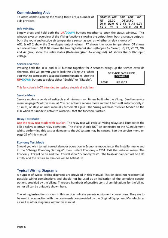
Commissioning Aids To assist commissioning the Viking there are a number of aids provided.
Info Window Simply press and hold both the UP/DOWN buttons together to open the status window. This window gives an overview of the Viking functions showing the output from both analogue outputs, both the room and outside air temperature sensor as well as whether a relay is on or off. AO1 & AO 2 show the 2 Analogue output values. RT shows the room temperature. OT shows outside air temp. D1 & D2 shows the two digital input status (0=open 1= Closed). G, Y3, Y2, Y1, OB, and Ax (aux) show the relay status (0=de-energised 1= energised). A1 shows the 0-10V input voltage.
Service Override Pressing both the <F1> and <F3> buttons together for 2 seconds brings up the service override shortcut. This will permit you to lock the Viking OFF when you wish to temporarily suspend control functions. Use the UP/DOWN buttons to select either “Enable” or “Disable”. This function is NOT intended to replace electrical isolation.
Service Mode Service mode suspends all anticycle and minimum run timers built into the Viking. See the service menu on page 22 of this manual. You can activate service mode so that it turns off automatically in 15 mins, or stays on until manually turned off again. The Viking will flash “Service Mode” on the LCD when this mode is active to warn you that the function is active.
Relay Test Mode Use the relay test mode with caution. The relay test will cycle all Viking relays and illuminates the LED displays to prove relay operation. The Viking should NOT be connected to the AC equipment whilst performing this test or damage to the AC system may be caused. See the service menu on page 22 of this manual.
Economy Test Mode Should you wish to test correct damper operation in Economy mode, enter the installer menu and in the “Change Economy Settings?” menu select Economy = TEST. Exit the installer menu. The Economy LED will be on and the LCD will show “Economy Test”. The fresh air damper will be held at 10V and the return air damper will be held at 0v.
Typical Wiring Diagrams A number of typical wiring diagrams are provided in this manual. This list does not represent all possible wiring combinations and should not be used as an indication of the complete control options provided by the Viking. There are hundreds of possible control combinations for the Viking so not all can be uniquely shown here. The wiring instructions shown in this section indicate generic equipment connections. They are to be used in conjunction with the documentation provided by the Original Equipment Manufacturer as well as other diagrams within this manual.

Page 7
Typical Heat Pump System – 4 Compressors
In this example the Viking is running a heat pump system with 4 compressors providing 4 stages of heating and 4 stages of cooling. The Viking is being powered via 240VAC in this example. DIP Switch Settings Sw1 Off – Rev in Heat On – Rev in Cool Sw2 Off – HP Mode Installer Options For 4 compressor systems Set Aux relay = Comp 4
2 Stage Cooling With Drive Open Drive Closed Hot Water Valve
The first stage heating and cooling relays in the Viking are a changeover type permitting you to drive a heating and/or cooling valve open and closed. DIP Switch Settings Sw1 Off – Fan on with heat Sw2 On – HC Mode Installer Options None required.

Page 8
2 Stage Heat With Modulating Cooling Control
In Valve Mode both the relays and 0-10V outputs work in tandem, permitting the Viking to modulate the 0-10V valve and also call for the circulating water pump on a cooling demand if required. Belimo valve terminal numbers are shown in this example. DIP Switch Settings Sw1 Off – Fan on with heat Sw2 On – HC Mode Installer Options Set Aux relay = Aux heat SetY1= Cool
Single Stage Water Sourced Heat Pump
This is similar to a standard single stage heat pump except that the auxiliary input is set to shut down the Viking on loss of water, thereby protecting the system. This fault input can be used as a phase fail input or any other safety interlock. The Viking LCD will indicate when a fault (low water) is detected. DIP Switch Settings Sw1 Off – Rev in heat On – Rev in cool Sw2 Off – HP Mode Installer Options Set AUX input 1 to Fault.

Page 9
0-10V Wiring The Viking has 2 x 0-10 Volt outputs that can be set to perform pre-set functions that are selectable by the installer. See the 0-10V options detailed in the installer menu shown on page 20 of this manual.
Sensor Wiring The Viking will accept two types of temperature sensors. The standard 2 wire sensor and the more advanced “Smart” 4 wire sensor that are capable of performing additional control functions.
2 Wire Sensors The standard 2 wire sensors are suitable for room temperature monitoring only. There are a number of types of 2 wires sensors available, an overview is provided below. 2 wire sensors connect to the “room sensor” and the “common” terminal next to it on the Viking. 2 wire sensor are not polarity dependent. RS-1 – It uses 2 wires to communicate the room temperature to the Viking. The RS-1S sensor is identical to the RS-1 described above except that it is fitted with a switch that initiates the after-hours run timer incorporated into the Viking controller. The RS-1S sensor is supplied as standard in the box with each Viking controller. The RS-A (S) additionally permits a +/- 4c adjustment of room temperature from the installer defined set point. This sensor is perfect for permitting the room occupants to ‘trim” the room temperature without making large adjustments. For projects that present difficulty in running wires for sensors, Smart Temp also offer the RS-W (non-adjustable), & RS-WA (+/- 4c adjustable) wireless room temperature sensor. This sensor is fitted with an afterhours run switch. The RS-W has a typical indoor range of approximately 30 meters. Duct sensors (RS-1D) and averaging sensors (RS-2) are also available that permit additional temperature monitoring options.
Additional functions using the 2 wire sensor Auto Off or Vent Mode You can switch the Viking to Ventilation Mode (or OFF) by manipulating the sensor wiring by placing an inline switch in the sensor cable. This works whether you use the standard (RS-01) room sensor or the adjustable (RS1-A) sensor. The Viking automatically detects the 2 wire sensor and when absent the Viking will behave in a number of ways as set in the Viking installer menu. See the installer menu options on page 17 for additional information on this function.
Off – An open circuit room sensor turns the Viking OFF. Vent – An open circuit room sensor will permit the indoor fan only to operate during occupied “Start” periods. Full Vent - An open circuit room sensor will run the indoor fan for as long as the sensor open circuit exists – regardless of current program.

Page 10
After Hours Run Function By placing a normally open momentary press button anywhere on the sensor line (or internally fitted in the RS-1S shown right) the Viking after- hours run timer can be initiated or cancelled. Smart Temp P/N RS-1S with red AH switch shown.
Combinations of the options above are possible. For example from a single 2 wire sensor it is possible to measure room temperature, offset the room temperature thereby altering comfort levels by +/-4c, initiate (or cancel) an afterhours heating or cooling call, shut the Viking down or place it in fan only Ventilation Mode.
Averaging Room Sensors When it is necessary to measure the room temperature in multiple locations the Viking is capable of using a network of room sensors and have the Viking control to an average of these temperatures with the 2 wire sensor. An example of averaging in 2, 3 and 4 places is shown using a
combination of Smart Temp RS-1 & RS-2 sensors. These averaging combinations can also take advantage of the advanced sensor functions such as Vent Mode or After Hours start if necessary. To use the “After-hours” function with averaging sensors the after-hours switch must be wired so that it affects the entire sensor input on the Viking and not just one sensor. See the diagram for the 4 averaging sensors example below.
It is highly recommended that screened single pair cable of 0.2mm diameter or larger be used on cable runs in excess of 10 meters or when the cable is run near high voltage / high frequency cabling.
4 Wire Sensors When you wish to use the outside economy function and/or provide a wall sensor with room temperature and set temperature display and adjustment then the “Smart Sensors” may be used. These are a 4 wire addressable “communicating” sensor that do not suffer from line losses or other problems that cab normally be associated with 2 wire sensors. Any 2 wire sensor or sensor network wired to the Viking is automatically disabled when the Viking detects an indoor Smart Sensor fitted. You are not permitted to use 2 wire and indoor 4 wire “Smart Sensors” simultaneously. “Smart Sensors” are available with a LCD and buttons, or as a blind sensor without display or buttons.

Page 11
Sensor with Display. (P/N RS-SSD)(SSD ver II – pictured requires Viking with firmware version 2.8 or greater)
Smart Temp Smart Sensors measure both humidity and temperature and are used when economy cooling is required or when you wish the occupants to be able to makes limited adjustments to the Viking operation. Two versions of Smart Sensors are available. The display version of the Smart Sensor is fitted with a backlit LCD and buttons that permit the set temperature to be adjusted within the Heating and Cooling set limits as set within the Viking controller if enabled. See setting heating & cooling limits on page 15 in the installer menu “Change Temperature Control Limits”. When displayed, pressing the “After Hours” button will start the after-hours run timer for the period of time pre-set in the Viking installer menu. See after hours run timer on page 15. If displayed, the On/OFF button permits you to turn the Viking OFF manually, overriding any time clock schedules if set. Pressing the On/Off button again will return the Viking to its previous state, (if the Viking is set to manual control the Viking will be “ON”, if under time clock control the Viking will run its schedule and be on or off based on that schedule) Sensor without Display (P/N RS-SS) The standard “Smart Sensor” simply measures temperature and humidity without permitting local set point adjustment or display etc. This type of sensor is essential for use as an outside air sensor and can be used for an inside sensor if required. NOTE - this sensor is NOT water resistant and therefore should be mounted in such a way that protects the sensor from rain. Smart Sensors have their own set of “TT” terminals where you are permitted to connect a standard 2 wire dry bulb sensor for remote temperature monitoring. This input overrides the internal Smart Sensor dry bulb sensor only. Humidity is still measured at the Smart Sensor.
Manuals are provided with the Smart Sensors that provide detail on the functions and settings of the Sensors.
Smart Sensor Wiring Terminals 1 & 4 power the Smart Sensor (12v DC +/- 4v is normal) while terminals 2 & 3 communicate data between each sensor and the Viking. The sensors must be wired in series only and no two sensors should have the same DIP switch address on the sensor network. If multiple room sensors are fitted, the Viking will control to the average temperature / humidity of all these sensors. Alternatively if set under the installer menu option “ Change Sensor Performance” menu shown on page 15, you are able to select High Heating & Low Cooling when using multiple Smart Sensors(Version 2.9 Viking firmware required).
Note, when short of cabling you may power the Smart Sensor locally from a 12VDC power supply and simply connect the Viking to the Smart Sensor using terminals 2 & 3.
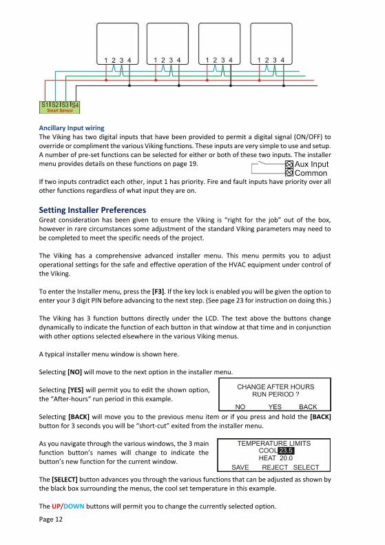
Page 12
Ancillary Input wiring The Viking has two digital inputs that have been provided to permit a digital signal (ON/OFF) to override or compliment the various Viking functions. These inputs are very simple to use and setup. A number of pre-set functions can be selected for either or both of these two inputs. The installer menu provides details on these functions on page 19. If two inputs contradict each other, input 1 has priority. Fire and fault inputs have priority over all other functions regardless of what input they are on.
Setting Installer Preferences Great consideration has been given to ensure the Viking is “right for the job” out of the box, however in rare circumstances some adjustment of the standard Viking parameters may need to be completed to meet the specific needs of the project. The Viking has a comprehensive advanced installer menu. This menu permits you to adjust operational settings for the safe and effective operation of the HVAC equipment under control of the Viking. To enter the Installer menu, press the [F3]. If the key lock is enabled you will be given the option to enter your 3 digit PIN before advancing to the next step. (See page 23 for instruction on doing this.) The Viking has 3 function buttons directly under the LCD. The text above the buttons change dynamically to indicate the function of each button in that window at that time and in conjunction with other options selected elsewhere in the various Viking menus. A typical installer menu window is shown here. Selecting [NO] will move to the next option in the installer menu. Selecting [YES] will permit you to edit the shown option, the “After-hours“ run period in this example. Selecting [BACK] will move you to the previous menu item or if you press and hold the [BACK] button for 3 seconds you will be “short-cut” exited from the installer menu. As you navigate through the various windows, the 3 main function button’s names will change to indicate the button’s new function for the current window. The [SELECT] button advances you through the various functions that can be adjusted as shown by the black box surrounding the menus, the cool set temperature in this example. The UP/DOWN buttons will permit you to change the currently selected option.

Page 13
The [SAVE] button will save the changes and exit this window. The [REJECT] button will exit this window discarding any changes made. The table provided below provides a detailed description of the various menu items, their functions and the range the values that can be set where appropriate. A list of the Basic & Advanced Installer Menu with details of the options within each menu is provided below. (Ver 2.9 firmware or later) Note - Entering the installer menu will shut down the HVAC system until you exit this menu. The HVAC system will then restart again after having waited for any set time delays to expire once you exit this menu. To advance through the menu, simply press the <F1> button. By answering “NO” to “Do you want to enter the current menu” option will move you to the next menu option. Answering “YES” will enter the menu where you will be able to adjust the highlighted option with the UP/DOWN buttons. Using the [SELECT] button (when displayed) will permit you to adjust other options within the current window.
Basic Menu Change Programming Options? Change Auxiliary Relay Functions? Change Auxiliary Input Functions? Change Economy Settings? Change Analogue Output Settings? Exit
Advanced Menu Change System PIN? Change Button Lock? Change Programming Options? Change Temperature Control Limits? Change Setback Temperature? Change After Hours Run Period? Change Sensor Performance? Change Compressor Staging Limits? Change Compressor Control Options? Change Compressor Timing Options? Change Room Sensor Functions? Change Auxiliary Relay Functions? Change Indoor Fan Options? Change Unoccupied Mode Settings? Change Auxiliary Input Functions?
Change 0-10V Input Settings? Change Analogue Output Settings?
Change Display Settings? Change Analogue Output Settings? Change Economy Settings? Change Night Purge Settings? Change PI Settings? Change Network Override Settings? Edit Communications Settings?
Enter Service Setting Menu? Exit Installer Menu?
Page 14
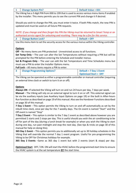
1 Change System Pin? Default Value = 021
The Viking has a 3 digit PIN from 000 to 199 that is used to access various menu items if enabled by the installer. This menu permits you to see the current PIN and change it if desired. Should you wish to change the PIN, you must enter it twice. If both PINs match, the new PIN is updated and must be used on all future PIN requests. NOTE: If you change and then forget this PIN the Viking must be returned to Smart Temp or an authorised service agent for unlocking and resetting. There may be a fee for this service.
2 Change Button Lock? Default = OFF
Use this menu item to set the security access for the various menus within the Viking controller. Options Off – No menu items are PIN protected - Unrestricted access to all functions. Set Temp Only – The user can alter the Set Temperatures without requiring a PIN but will be prompted for the PIN before entering the Schedule and Installer menus. Set & Program Only – The user can edit the Set Temperature and Time Schedules menu but must use a PIN to enter the Installer Options menu. Full Lock – All menu items require a PIN to enter.
3 Change Programming Options? Default = 7 Day 1 Event Optimised Start = OFF
The Viking can be operated as either a programmable controller or manual controller (requiring an external time clock or switch to turn it on or off). Options Always ON –If selected the Viking will turn on and run 24 hours per day, 7 days per week. Manual – The Viking will rely on an external signal to turn it on or off. This external signal can be via the auxiliary inputs (see Auxiliary Input Options on page 19) or the built in After-hours Run function as described on page 19 of this manual. Also see the Handover Functions described on page 30 of this manual. 7 Day 1 Event – This option permits the Viking to turn on and off automatically as set by the inbuilt time clock, once per day for the 7 weekly days. The On event is named “Start” and the Off event is named “Stop” 7 Day 2 Event – This option is similar to the 7 day 1 event as described above however you are permitted 2 starts and 2 stops per day. This is useful should you wish the air conditioning to be off for part of the day (during a lunch break for example) or when you wish the Viking to start during one day, run past midnight and stop the next day. (See tips & tricks on page 30 of this manual for help on doing this). 365 Day 1 Event – This option permits you to additionally set up to 30 holiday schedules in the Viking that will override the normal 7 day 1 event program. Useful for pre-programming the Viking to be OFF for Christmas holidays for example. 365 Day 2 Events –Same as 365 day 1 event but with 2 events (start & stops) per day. Optimised Start OFF / ON. ON will start the HVAC before the programmed start time to ensure the HVAC system is at the set temperature BY the start time.

Page 15
4 Change Temperature Control Limits? Default = Heat 49°C & Cool 6°C
If permitted, the user can have the ability to adjust the heating and cooling set points. The range of the user adjustment can be limited if desired by setting the values below. Options Heat – The highest heating set point that can be adjusted. (6°C to 49°C) Cool – The lowest cooling set point that can be adjusted. (6°C to 49°C) Note: Regardless of where these set point limits are set, the Viking will ensure that at all times the cooling set point is above the heating set point. If necessary, the Viking will “push” set points apart to ensure the set points do not overlap.
5 Change Setback Temperature? Default = Heat Off & Cool Off
Rather than shutting the heating and cooling system completely off during the STOP events, the Viking can automatically maintain a more energy efficient set point during this time. This value can also be used as a set temperature during Holiday events if desired. See “Setting Holiday Schedule” on page 25 of this manual. The Fan will run in “Fan Auto” mode to maintain any set back temperatures that are set. Options Heat – The setback heating temperature. (Range Off –then 6°C to 49°C) Cool – The setback cooling temperature. (Range 6°C to 49°C then OFF)
6 Change After Hours Run Period? Default = 2 Hours
The Viking has a built in after-hours timer that, when initiated will replace the current “Stop” or “Holiday Event” set points with the “Start” heating and cooling set points and Fan Mode. This override period is timed and at the conclusion of this timed period the Viking will return to the programmed set points for the current date and time. Information on initiating the after-hours timer can be found on page 27 of this manual. Hint: To disable this function set this value to OFF
7 Change Sensor Performance? Default = 0.0 & Nor& SS
The Viking has 3 temperature sensor inputs. Room - The 2 Wire Room sensor input O/A - Smart outside air sensor Coms - Smart room sensor Options Calibration – adjust this value of the selected sensor by +/- 4.5°C. This is used mostly to offset any temperature accuracy errors caused by long cable runs with the 2 wire sensors. Adjusting any Smart Sensor readings should NEVER be necessary. Response Speed - The Viking will permit you to select how rapidly it will respond to room temperature changes. Options are VFAST / Fast / Nor (Normal) / Slow / VSLOW High / Low select (Ver 2.9 or later firmware) - (only applicable with multiple indoor Smart Sensors) SS = Standard HI = High Select LO= Low Select
Page 16
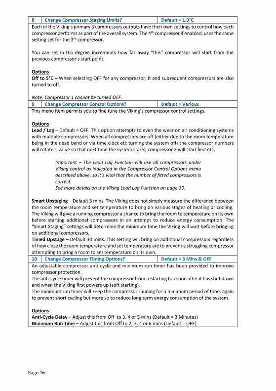
8 Change Compressor Staging Limits? Default = 1.0°C
Each of the Viking’s primary 3 compressors outputs have their own settings to control how each compressor performs as part of the overall system. The 4th compressor if enabled, uses the same setting set for the 3rd compressor. You can set in 0.5 degree increments how far away “this” compressor will start from the previous compressor’s start point. Options Off to 5°C – When selecting OFF for any compressor, it and subsequent compressors are also turned to off. Note: Compressor 1 cannot be turned OFF.
9 Change Compressor Control Options? Default = Various
This menu item permits you to fine tune the Viking’s compressor control settings. Options Lead / Lag – Default = OFF. This option attempts to even the wear on air conditioning systems with multiple compressors. When all compressors are off (either due to the room temperature being in the dead band or via time clock etc turning the system off) the compressor numbers will rotate 1 value so that next time the system starts, compressor 2 will start first etc.
Important – The Lead Lag Function will use all compressors under Viking control as indicated in the Compressor Control Options menu described above, so it’s vital that the number of fitted compressors is correct. See more details on the Viking Lead Lag Function on page 30.
Smart Upstaging – Default 5 mins. The Viking does not simply measure the difference between the room temperature and set temperature to bring on various stages of heating or cooling. The Viking will give a running compressor a chance to bring the room to temperature on its own before starting additional compressors in an attempt to reduce energy consumption. The “Smart Staging” settings will determine the minimum time the Viking will wait before bringing on additional compressors. Timed Upstage – Default 30 mins. This setting will bring on additional compressors regardless of how close the room temperature and set temperature are to prevent a struggling compressor attempting to bring a room to set temperature on its own.
10 Change Compressor Timing Options? Default = 3 Mins & OFF
An adjustable compressor anti cycle and minimum run timer has been provided to improve compressor protection. The anti-cycle timer will prevent the compressor from restarting too soon after it has shut down and when the Viking first powers up (soft starting). The minimum run timer will keep the compressor running for a minimum period of time, again to prevent short cycling but more so to reduce long term energy consumption of the system. Options Anti-Cycle Delay – Adjust this from Off to 3, 4 or 5 mins (Default = 3 Minutes) Minimum Run Time – Adjust this from Off to 2, 3, 4 or 6 mins (Default = OFF)

Page 17
11 Change Room Sensor Functions? Default = OFF
The room temperature sensor wiring can be used for additional functions other than just measuring the room temperature. When this sensor is open circuited (or permanently short circuited) and seen as missing by the Viking, additional functions can be performed. Options Force Off – When the room temperature sensor is absent, the Viking will shut down. Ventilation – When the room temperature sensor is absent the Viking will keep the indoor fan running during the “Start” event programmed time. There will be no heating or cooling. Full Vent – When the room temperature sensor is absent the Viking will keep the indoor fan running regardless of time or set schedules. There will be no heating or cooling – use this with caution. Note: A fire or fault input will shut down both Full Vent and Ventilation Modes instantly.
12 Change Auxiliary Relay Functions? Default = OFF
The Viking is fitted with an ancillary volt free relay to which you are able to assign pre-set functions. Many of these functions have an additional setting associated with them, such as when selecting the high temperature alarm the Viking permits you to set the alarm value. Options Off – This relay is not used. Time & After Hours – the auxiliary relay will close when the Viking is running the “Start” program or when the after-hours timer is active. See Tips and Tricks on page 30 of this manual for details on using one Viking as a master time clock. After Hours Only – the auxiliary relay will close only when the after-hours timer is running. This can be used to pass the after-hours run information to additional devices. Time Clock Only – The auxiliary relay will close when the Viking time clock is running the “Start” program. If the after- hours timer is initiated, this relay will remain inactive. Compressor 4 – The auxiliary relay is assigned as compressor 4. Compressors 1 - 3 must be active for this function to operate. See Compressor Staging Limits on page 16 of this manual. Aux Heat – In this mode, the auxiliary relay is assigned as auxiliary heat relay, providing a heating call after all compressors have finished calling for heat or as a 2nd stage of heating in Heat Cool Mode (Sw 1 ON). Heat and Cool – The auxiliary relay will close whenever the Viking is calling for heating or cooling. (ver 2.9 or later) Cool – The auxiliary relay will close whenever the Viking is calling for cooling. (ver 2.9 or later) Heat – The auxiliary relay will close whenever the Viking is calling for heating. (ver 2.9 or later) Low Alarm - The auxiliary relay will close when the room temperature falls below the low temperature alarm limit. It will auto reset when the room temp rises more than 2°C above the alarm set point. Note –if set, the Low Alarm will operate as long as the Viking is powered, even when stopped or OFF. (ver 2.9 or later) Hi Alarm – The auxiliary relay will close with the room temperature exceeds high temperature alarm limit. It will auto reset when the room temp falls more than 2°C below the alarm set point. Note – if set, the High Alarm will operate as long as the Viking is powered, even when stopped or OFF. (ver 2.9 or later) Economy - The auxiliary relay will close whenever the Viking calls for economy mode. Humidity - This permits the Viking to control a humidifier if the indoor humidity becomes low. You are also given the opportunity to set the alarm threshold. (ver 2.9 or later) Network – The auxiliary relay can be controlled (opened or closed) via MODbus or BACnet.

Page 18
13 Change Indoor Fan Options? Default Locked ON & No Purge
The indoor fan in the Viking can be controlled by the user if desired (permitted to select Auto Fan or Fan On Mode) or locked into On or Auto Mode as set by this menu. Options Unlocked – The user can select Fan Auto or Fan On Mode for the “Start” event without restriction. Locked Auto – The user cannot adjust the Fan Mode. When the “Start” event is running the fan will be in Auto Mode where the fan will cycle on and off with the heating and cooling. Locked On – When the “Start” event is running, the fan will be held on continuously regardless of the need for heating or cooling. The fan will turn off at the ‘Stop’ program. Purge - A fan purge period of 0 (Off) to 10 minutes, in 1 minute steps, can be set. This will hold the fan on for a purge period of time after the set point has been reached and the heating and cooling has stopped.
14 Change Unoccupied Mode Settings? Default Heat / Cool Off /A Fan
The Viking has an “Unoccupied” Mode. When in unoccupied mode the current active set points and fan mode are replaced by the Heat, Cool and Fan settings in this menu. The Unoccupied Mode can be initiated via the auxiliary inputs (see page 19) or via the Holidays Function (see page 25). Options Cool – The cooling set point to use during the unoccupied period. (Default OFF) Heat– The heating set point to use during the unoccupied period. (Default OFF) Fan– The Fan Mode to use during the unoccupied period. (Default Auto) Caution – If you set the Fan Mode to “ON” in this menu and then use the unoccupied mode for a holiday event, then the fan will run continuously, 24 hours per day during that holiday event period regardless of the need for heating and cooling. See Holiday Programming on page 25 for more detail.

Page 19
15 Change Auxiliary Input Functions? Default = Not Used
Two auxiliary inputs have been provided. These are digital inputs and each of these 2 inputs has the same list of options. In the event of a conflict, auxiliary input 1 will have priority. A fire or fault input regardless of what input calls them has absolute priority over all Viking inputs. Options Not Used – This input is disabled. Fire – Normally closed input. If this input is open the Viking will shut down all functions, all relays will open and both 0-10V signals will be 0 volts. This is an instant shutdown; minimum run times and fan purge periods will be cancelled. The LCD will show “FIRE” to indicate this mode is active. Occupancy – Initiating this function will cause the Viking to replace the current set points with the installer set Occupancy set points and Fan Mode for as long as this input is active. AH Initiate – A short On/Off signal (Pulse) on this input will initiate or cancel the Viking’s after hours run timer function. During the after-hours run time, the Viking will use the “Start” set points and Fan Mode for the timed after hours run period. Force On – When this input is active, the Viking will use the “Start” program’s temperatures and Fan Mode for as long as this input is active. Delay Start – Initiating a Delay Start is similar to the Force On Function described above except that rather than starting immediately the Viking will wait a random period of time, up to 90 seconds, before starting the A/C system. This is useful if you have multiple Vikings running from a single time clock to protect the building’s power system. Fault NC – Closing this input will shut the Viking down. The LCD will show “System Fault”. Fault NO – Opening this input will shut the Viking down. The LCD will show “System Fault”. Fresh Air – When this input is active and Economy Mode is enabled, the Viking will open the fresh air damper and close the return air damper to introduce fresh air into the building. Typically this input is connected to an indoor air quality monitor. Auto – When Auto mode is used, the Viking will run based on its time schedule only when this input is closed and stop when the input is open. This mode fits standard Mechanical Auto/On/off switch logic.
16 Change 0-10v Input Settings Default = OFF
Off - This input is not used. IAQ Threshold - The voltage seen at the 0-10V input below this value will not initiate any fresh air introduction into the building. This is the normal “background” level that is acceptable. Range is the amount the fresh air damper will open when the 0-10V input measures 10V. For example, if using a 0-2000ppm CO2 sensor where you want the damper to open to a maximum of 60% when full fresh air is required and want the damper closed when the indoor CO2 is below 500ppm. Set the threshold for 2.5V ((2000/500ppm)=4 10V/4 = 2.5)) Set the range to 60%
17 Change Display Settings? Default = Deg C & 12 Hour
Set the default temperature and time format display for the Viking from this menu option. Options Display – Degree C or F format. Clock – 12 hour (am/pm format), 24 hour format or Off (Note Setting the clock to OFF will force the Viking into Manual Mode )

Page 20
18 Change Analogue Output Settings? Default = NOT USED
The Viking has two analogue outputs which can be assigned specific functions as detailed below. Each of the two analogue outputs has the same functions. Options Not Used – The output is not used. Output is 0V H & C – By selecting this option this single output will modulate for both heating and cooling. This is mostly used by BMS systems for example to obtain feedback about how far the room is from set point for both heating and cooling modes. Cool – This sets the analogue output to control a 0-10 cooling valve. When you select “Cool” you are then given the option to select the span for the cooling valve, i.e. how far above set point the 0-10V output is at 10V. Heat – This sets the analogue output to control a 0-10 heating valve. When you select “Heat” you are then given the option to select the span for the heating valve, i.e. how far below set point the 0-10V output is at 10V. Return Air – This assigns the analogue output to control the inside economy cycle damper. When economy is used, this damper will modulate closed as more outside air is used. Fresh Air – This assigns the output to control the outside economy damper. Normally this is at 0V until economy air is used but can sit above 0V if the DVT function is set (see Change Economy Settings below). The outside damper is also used for the Night Purge Function as described below. Type – 0-10V or 2-10V type valves. This applies to BOTH valves.
19 Change Economy Settings? Default = OFF
Please note, you must assign one of the 0-10V analogue outputs as described above before being permitted to adjust the economy settings within this menu. The Viking will automatically change this setting to “ON” when you assign at least one analogue output to Fresh or return air. When using outside air for free cooling (see Economy Function on page 27) the suitable temperature range of outside air can be defined. Options DVT- Off to 90%. The Day Ventilation Time Function will open the outside air damper by this fixed amount regardless of other economy function settings but only while the building is occupied. This is to introduce a fixed amount of fresh air into the building to keep the indoor air quality acceptable when the building is occupied. The damper will close when the building is unoccupied to prevent heat loss overnight. Off - Economy cycle is not used / required. On - Economy Cycle is ready. Test - Viking will behave as if 100% outside air is required. RH Limit – When the outside Smart Sensor is used and the normal 2 wire sensor is used for room temperature measurement the Viking will permit you to set a high outside relative humidity limit. When the outside air is above this level outside air will not be used for cooling. If both inside and outside Smart Sensors are used, then the economy settings window will show “Enthalphy Based”. There are no adjustments required as this Viking will compare the inside and outside air enthalphy and base the use of outside air on these values. Note: When the outside air cannot adequately cool the room the Viking will suspend the use of outside air and replace it with electric cooling.

Page 21
20 Change Night Purge Settings? Default = OFF
The Viking can use outside air to cool a building at night when the air is cooler, to cool the building and prepare the building for the next day’s use. Options Off / Fan / Aux – Turns the Night Purge Function on or off and sets which relay should close to draw in outside air during the night purge period. “Fan” will use the normal equipment fan. By
selecting “Aux” the Viking will use the auxiliary relay to control the night purge fan.
Temp – Sets the desired temperate to cool when night purge is operating. RH Limit – Maximum outside RH level suitable for night purge. (requires “Smart” outside sensor) When - Sets the night purge start. T0 - Sets the night purge stop time. (Note - night purge requires 1 analogue output to be set for “Fresh Air Function”.)
21 Change PI Settings? Default = P Only
The Viking can apply integral action to its outputs if so desired. This action will dynamically alter the control output in such a manner to bring the room to set temperature more quickly when using multistage equipment or equipment with variable capacity. PI control will not assist with a fixed capacity system. Y1 Output, Y2 Output or multistage relay outputs can be given PI control. You have 99 degrees of proportional and integral action to choose from. You will be given 2 settings when selecting PI control. The first digits are the “P” (proportional), the second digits are the “I” (Integral). Unfortunately there are no best “defaults” for this function other than OFF. The settings should be made to suit the application, the size of the equipment and load will have great impact on how effective these settings will be. Trial and error will provide the best outcome. P only – Proportional control only P1 – Slight Proportional action. P 99 – Heavy Proportional integral action. I 1 – Slight Integral action. P 99 – Heavy Integral action. If in doubt - leave this setting as P only.
22 Change Network Override Settings? Default = OFF / Auto
The Viking is a very capable standalone HVAC controller however, when connected to a MODbus master many settings or control functions can be monitored or overridden. This menu permits resetting of critical control functions should the MODbus network fail. Options O/Ride Off – the Viking internal clock and schedule is in control. Force On – The BMS system is holding the Viking on (in “Start” Mode). Force Off – The BMS system is holding the Viking off (in “Stop” Mode). Relay Auto – The Viking will control its 6 relays based on room and set temperature. Network – the Viking relays are being controlled via the controlling BMS.

Page 22
23 Edit Communications Settings? Default = 7 / 9.6K /MODbus
The Viking is fitted with integrated MODbus RTU & BACnet MS-TP communications drivers and firmware. This permits the Viking (or many Vikings) to be controlled remotely via a PLC or BMS if required. Communications information is provided in a separate document. Options MODbus Address – This sets the unique address for “this” Viking on the network. Every device on the network must have a unique network address. Range 0 - 255. Zero NOT recommended. Baud Rate – This sets the communications speed. 4.8K, 9.6K or 19.2K 38.4 baud. All devices on the network must communicate at the same speed. MODbus / BACnet – Sets the communications protocol.
24 Enter Service Settings Menu? Default = Off (All)
This menu permits you to perform some minor maintenance and testing on the Viking, as well as permits you to quickly commission the A/C system under Viking control. Options Relay Test – Selecting [YES] will cycle all Viking relays (and LEDs) to verify correct operation. It is recommended that this test is not performed while connected to an A/C system as this may stress the A/C system. Service Mode – Enabling this function will reduce (or eliminate) all of the Viking anti cycle time delays, minimum run timers and other protective delays. Selecting “15 min” will automatically turn the Service Mode off after 15 minutes. Selecting “ON” will leave this menu on until manually deactivated. The LCD will show when the Service Mode is on. Factory Reset – select [YES] and then again in the confirmation window to reset the Viking back to the factory default settings. This will erase all programs, holiday schedules and all other values. The Viking will return to the “out-of-box” state.
25 Exit Installer Menu?
Selecting “YES” will exit the service menu. Selecting “NO” will bring you to the first option of the service menu “PIN NUMBER SELECT”. Note: If no buttons are pressed after 30 seconds the installer menu is exited automatically. If you press and hold the [BACK] button in any main menu window you are exited from the installer menu.

Page 23
Operation
The PIN Prompt The Viking has 3 main menus where various parameters can be set. Some or all of these menus may be protected by a PIN. This PIN can be changed from the factory default of “021” by the installer. The example below assumes this PIN has not changed. If the PIN has changed and you know the new PIN, use those digits rather than the ones given in this example. If the PIN has changed and the new PIN is not known by you, the Viking may need to be returned to Smart Temp or an authorised service agent for unlocking. There may be a fee for this service. If the PIN is protecting the menu you are trying to enter, you will be shown the “Changes Not Permitted” window to warn you that you must enter a PIN to proceed. After a few moments you will be shown the PIN window where you must correctly enter the PIN before proceeding. Pressing the UP/DOWN buttons will adjust the currently highlighted number. The first digit in the default PIN is “0” (Zero) so simply press the [NEXT] button to advance to the next digit. Adjust the second digit to “2” (Two) and again press the [NEXT] button to advance to the third digit. Adjust the third digit to “1” (One). You should now have the PIN window showing “021”. If you have made an error, pressing the [BACK] button will permit you to adjust a previous digit. Press the [ENTER] button to proceed. If the PIN was entered correctly you will be permitted to proceed, if not, you will be ejected from this window. You may try again.
Setting the “Start” event or run temperatures When the Viking is running it will maintain the user / installer defined heating & cooling set temperatures. To set the “Start” event temperatures press the <F1> (settings button). Use the [SELECT] button to select fan mode (if applicable) and the heating and cooling set points, adjust with the UP/DOWN buttons to your desired value. When the Viking is running the “Stop” event the Viking will maintain the setback temperatures (see setback on page 15 of this manual).
Programming The Viking has the ability to automatically turn the HVAC system on and off based on its internal time clock and the user / installer defined schedule. There are 4 options in the schedule menu that can be accessed with the <F2> menu. These are detailed below. Setting the Clock - Will set the current time and date. Setting the Daylight Savings Time – Used to set the daylight savings start and end date and time. Setting the Program – Used to set the 7 day start and stop times. Setting the Holiday – This sets the date the holiday schedules will start and end.

Page 24
If these menus are PIN protected, it is necessary to enter the correct PIN before accessing the various menu items.
Setting the Clock Press the <F2> “Schedule” button. If you are prompted to enter a PIN, see “The PIN Prompt” on page 23. Depending on values set within the Viking installer menu you will be presented with a number of options. Use the [SELECT] button to highlight the word “CLOCK” and then press the [SET] button. Use the [SELECT] button to advance through the various parameters such as Date, Month, Year, Hour and Minute and then adjust these values with the UP/DOWN buttons to the desired value. (The Viking will calculate the day of the week) Press [SAVE] to save the new time parameters and exit the menu. The [REJECT] button will exit this menu discarding changes.
Setting Daily Schedules The Viking can be individually programmed to “Start” and “Stop” the building’s HVAC system at a separate time for each day of the week if necessary. When the Viking is in “Start” Mode it will use the “Start” program set temperatures (See Setting the “Start” Set Temperatures on page 24) and when in the “Stop” Program Mode it will use the Setback set temperatures as set by the installer (see Setting the Setback Temperatures on page 15). This provides around the clock temperature control. Additionally, the Viking has an inbuilt “after hours” run timer that can be manually initiated where the “Stop” program temperatures are temporarily replaced with the “Start” program temperatures for a predetermined period of time; typically 2 hours. (See the After Hours Function on page 15 for setting the parameters for this function). Note: Each daily schedule must start and end on the same day. You cannot set a schedule to start at 2pm Wednesday and end at 3am Thursday. To program past midnight see Tips and Tricks on page 30 of this manual. Setting a “Start” schedule time and “Stop” schedule time at the same time will cancel that schedule for that day, i.e. 8:00am start and 8:00am stop. Press the <F2> “Schedule” button for 1 second. If you are prompted to enter a PIN, see “The PIN Prompt” on page 23. Depending on values set within the Viking installer menu you will be presented
with a number of options. Use the [SELECT] button to highlight the word “Schedule” and then press the [SET] button to enter the 7 day programming menu.
You will be presented with the option to start / edit the program on Monday or select another day using the UP/DOWN buttons then press [NEXT] to proceed.

Page 25
Set the “Start” hour and minutes and the “Stop” hour and minutes for the day previously selected, Monday in this example. If you have 2 schedules per day you are given the option to swap back and forth between the 1st and 2nd daily
“Start” & “Stops” by selecting [2ND SCH]. Press [NEXT] to proceed. You can now copy the previously selected day’s program, Monday in this example, to the other days by using the [SELECT] button to choose the day you wish to copy to and then press the [NEXT] button to begin the copying process. The Viking will show “COPYING” and then permit you to re-enter the programming menu to program other days or exit to the main menu.
Set Holiday Schedules Up to 30 holiday events can be scheduled into the Viking. These holiday events will override the time and temperature settings of the “normal” 7 day programs events as described above and replace those event parameters with the holiday events parameters selected. A holiday event can be used just once and then expire or be a “perpetual” event that occurs at the same time every year until cancelled manually. Press the <F2> “Schedule” button. If you are prompted to enter a PIN, see “The PIN Prompt” on page 23. Depending on values set within the Viking installer menu you will be presented with a number of options. Use the [SELECT] button to highlight the word “Holiday” and then press the [SET] button. Use the UP/DOWN buttons to choose one of the 30 available holiday event placeholders. The holiday event placeholders will show either “Empty” if no holiday event is set in this placeholder or it will give the starting date of an existing holiday event. Press [SELECT] to enter the desired holiday event placeholder.
Use the [SELECT] button to highlight the desired option and use the UP/DOWN buttons to adjust to the desired value.
The Viking holiday program is very powerful and tuned to the needs of HVAC applications. A number of options are available to be chosen based on the needs of the particular holiday schedule. The top line of text in the above example shows the event number, in this example “Event 1”. You are then given an option to select a single day for this event or a range of consecutive days. This example shows a date range. As each holiday event can be for different lengths of time and can occur at various times of the year, further the Viking will permit you to choose from a number of heating and cooling set points that will apply for the selected holiday event. In this example “OFF” has been selected. The available options are: Off – The heating and cooling system will be off during this event. SB – (Setback - see page 15 ) The Viking will use the current Setback temperatures for the duration of the holiday event. The fan will cycle with the heating and cooling i.e. Auto Mode. OCC – (Unoccupied set point - see page 18) The Viking will use the current “unoccupied” set temperatures and Fan Mode for the duration of the holiday event.

Page 26
Caution - The fan will obey the Fan Mode settings in the unoccupied set point menu, so if “Fan On” Mode is selected in this menu, then the fan will run 24 hours per day for the duration of this holiday event. Setting the date for the event is a simple matter of stepping through the start and stop dates with the [SELECT] button and adjusting the date with the UP/DOWN buttons. To select a self-expiring 1 off event, choose the current or a select a future year for this holiday event. The Viking will show this year in the setting. When this event has passed the Viking will delete this event automatically. To set an event that occurs at the same time every year until manually cancelled, attempt to set a year prior to the current year as shown by the real time clock, the year number will change to a “P” to indicate this event is perpetual or permanent holiday event. A perpetual event will need to be manually deleted as they don’t expire automatically. Press [SAVE] to save the new time parameters and exit the menu. The [BACK] button will exit this menu discarding changes. Note:
All holiday events start and stop at midnight on the day(s) selected.
The after-hours run timer will operate during a holiday event if initiated and will use the normal Start Mode temperatures. (Not the “holiday” Heat / cool or fan setting).
The fault or fire inputs will cancel any holiday event for the duration of the fault or fire event.
All advanced functions such as economy cycle, fan purges and compressor control options operate during the holiday events to maintain any set temperatures programmed.
Setting Daylight Savings Times The Viking can automatically change its clock time based on the current daylight savings parameters set in this menu. Press the <F2>“Schedule” button. If you are prompted to enter a PIN, see “The PIN Prompt” on page 23. Depending on values set within the Viking installer menu you will be presented with a number of options. Use the [SELECT] button to highlight the text “DST” and then press the [SET] button.
Use the [SELECT] button to advance through the various parameters, such as the start day and month, the end day and month, what time to change the clock and whether you want the DST function on or off. Adjust the highlighted
values with the UP/DOWN buttons to the desired value. Press [SAVE] to save the new time parameters and exit the menu. The [BACK] button will exit this menu discarding changes.

Page 27
Advanced Features
Economy Cycle A typical economy cycle wiring diagram has been provided below. In this example the Viking is controlling a single stage heat pump. Other control configurations could also take advantage of the economy cycle mode of the Viking. For the economy cycle to operate you must assign at least one of the analogue outputs for economy cycle function in the “Change Analogue Output menu” (see page 20); either as Fresh Air damper, economy Return Air damper or both. You must also set economy cycle parameters in the Change Economy Settings menu (see page 20). Further as economy cycle relies on outside air temperature humidity values being available to the Viking you must use the outside “Smart Sensor” (and set high outside RH limits) or ideally install both the inside and outside Smart Sensors for full enthalphy based economy control. The example drawing below shows 24V Belimo brand damper actuators using the same 24V supply that is powering the Viking. Other power combinations are also possible. If in doubt please contact Smart Temp or an authorised distributor for application specific guidance. As some brands of dampers cannot easily operate in reverse (close at 10V) the Viking provides two 0-10V outputs, one forward acting and one reverse acting. These are shown as Fresh Air and Return Air in the analogue output menu. The sum of both 0-10V outputs is generally 10V unless the daytime ventilation function is set where the return Air damper may rest at a fixed voltage while the building is running. (Intended to introduce fresh air to maintain acceptable indoor air quality) The example provided below shows the Viking using both 0-10V outputs. Should you wish, you can simply use one output if desired and set one damper for reverse acting on the damper itself. The Viking provides you with information on the current status of the economy cycle from the main information screen. Simply press one of the up/down buttons to advance to the Economy Mode status window shown above. (Smart Sensor wiring info - Terminal 1 = 12VDC, terminal 2 = Data A, terminal 3 = data B, terminal 4 = 0V. Therefore if required, the smart sensor can be locally powered from 12VDC then using a screened pair to communicate between the Smart Sensor and Viking terminals 2 & 3)

Page 28
Economy Checklist. 1 Wire the fresh, return and relief / spill dampers to the Viking analogue outputs. Note which
Viking output is controlling which damper. For example analogue output 1 (Y1) is controlling the return air damper and analogue output 2 (Y2) is controlling the fresh air damper (as shown in the example above).
2 Wire the room temperature sensor to the Viking (2 wire or 4 wire versions of the sensors are acceptable) and wire the 4 wire Smart Sensor to the S1, S2, S3, S4 terminals. Set all 4 DIP switches in the Smart Sensor to ON. See the manual supplied with the Smart Sensor for more details on switch settings.
3 Enter the installer menu and set up the analogue outputs in the Viking to match the damper wiring. Enter the menu “Change Analogue Output Settings?” menu and Set AO1 = Return, Set AO2 = Fresh. Press <F2> Save. Page 20 details the analogue output settings within the Viking.
4 In the installer menu enter the “Change Economy Settings?” menu. Select Economy = ON. Press <F2> Save. Page 20 gives more detail on this.
5 Press & Hold the Back button <F3> to exit the installer menu. 6 Economy cycle is now setup.
Should you wish to test correct damper operation in Economy mode, in the installer menu enter the “Change Economy Settings?” menu. Select Economy = TEST. Exit the installer menu. The Economy LED will be on and the LCD will show “Economy Test”. The fresh air damper will be held at 10V and the return air damper will be held at 0V. You must exit economy mode test mode manually by setting economy mode back to Economy = ON. (If you forget the Viking will automatically exit economy test menu after 1 hour). Economy Logic The economy cycle of the Viking is used before stage 1 cooling is required and starts 0.1°C above the cooling set point if the outside air is suitable. If the indoor fan is in Auto Mode (Cyclic fan) and not running when the Economy Function is required the Viking will automatically start the indoor fan. If after some time the desired room temperature is not reached or in fact becomes warmer the Viking will automatically suspend the outside air function and replace it with normal A/C cooling to bring the room to set point. Economy Cycle function will be suspended. (In these cases the Economy LED will flash to indicate the outside air on its own is not capable of maintaining the target temperature.) Information on wiring Smart Sensors to the Viking is provided on page 11.
CO2 input As well as controlling Economy cooling shown above, the Viking permits you to additionally add a 0-10VDC CO2 sensor that regulates the introduction of outside air based on the indoor air quality of the building. Smart Temp or authorised distributor are able to offer a 0-2,000 ppm CO2 sensor with infrared sensor and LCD

Page 29
As the standard economy dampers are used, the Indoor air quality setting in the Viking can limit the maximum amount of fresh air introduced into the building. See the installer menu option “Change 0-10V input settings” on page 19 of this manual for setting the Indoor air quality settings.
Valve Control The Viking can control heating and/or cooling valves via a 0-10 or 2-10V signal. The span of the valves can also be individually set. The heating valve can be fully open (at 10V) when 3°C from set point while the cooling valve can be set to be fully open (at 10V) 1°C from set point. The Viking will also switch the heating and cooling relays when in Valve Mode. This permits the Viking to additionally control a circulating water pump or some other device when heating or cooling is needed. You will need to assign the 0-10V outputs to Valve function by selecting heating or cooling mode for the 0-10V output of the Viking. See page 20 for setting the 0-10V output function.
After Hours Timer The Viking has an Auto Off timer that can be used in multiple ways, most typically as an after-hours timer but can also be used in Manual Mode as an auto off run timer. Placing a normally open momentary push button (Bell Press) on the Viking’s room sensor input will activate or cancel this timer. “Anti-Bounce” logic is built into the Viking logic so that a single or multiple presses of the button (within a 10 second window) are seen by the Viking as a single call to start (or stop) the after-hours timer.
After Hours Timer Logic in Manual Mode If the Viking is set to “Manual Mode” (see programming options on page 14 of this manual) then the Viking will start and run for the duration of the after-hours timer period and then automatically turn off again. (See After-Hours Timer Period on page 15). This is useful for training rooms for example that are used intermittently. Simply manually start the run timer when the training room is in use knowing that after the pre-programmed time the Viking will shut down the HVAC system automatically.
After hours Timer logic in Programmable Mode If the Viking is set to one of the programmable modes (see Programming Options on page 14) then the Viking will automatically alternate between the “Start” and “Stop” programs based on the pre-programmed times. If during the “Stop” program the building becomes occupied, simply initiate the after-hours timer and the “Start” program temperatures are temporarily used for the present after-hours timer period (default 2 hours).

Page 30
Initiating / Cancelling the After Hours Timer The Viking room temperature sensor can be fitted with a normally open switch across the contacts. Pressing this switch for 1 or 2 seconds will temporarily “short” the temperature sensor, starting or stoping the after-hours timer. The Viking is also provided with a digital auxiliary input; again placing a normally open momentary switch across this input will start or cancel the after-hours timer. See “How to Set the Auxiliary Input Function” on page 19 for more information on this function.
Handover Relay The Viking has an auxiliary output relay that can be installer set to multiple tasks such as providing an additional stage of heating (Aux Heat Mode), an additional compressor for a reverse cycle system (Comp 4 Mode) as well as being used as a Handover Relay as well as providing other functions (See page 17). A useful function is to use this relay to indicate the Viking status or to control ancillary device such as toilet exhaust extraction fans, access control or lighting based on the current Viking status. Described in the Tips and Tricks section on page 30 is a method of using a single Viking’s time clock to control multiple Vikings, reducing the complexity of time clock programming and scheduling.
Compressor Lead Lag When controlling systems with multiple compressors, the Viking can attempt to even compressor wear by advancing the compressor numbers each time all compressors are off. So, for a 3 compressor system, first start will call compressor 1 as stage 1, compressor 2 as stage 2 and compressor 3 as stage 3. When set point is reached and all compressors are off, next time the system starts, compressor 2 will be stage 1, compressor 3 will be stage 2 and compressor 1 will be stage 3. It is important that the Lead Lag Function is set correctly and if the HVAC under Viking control has 2 compressors then the Viking must be set for a 2 compressor system. Do this by turning off compressor 3 (and 4) from the compressor control options in the Advance Installer menu on page 16 so that the Viking does not call for absent compressors.
Tips &Tricks Programming Past Midnight The Viking uses a daily time clock for scheduling. This means that a “Start” event and a “Stop” event must occur on the same day. The Viking cannot start the HVAC system at 4pm one afternoon and stop it again at 6am the next morning with a single event. To solve this problem, the Viking has the ability to have 2 daily events. This option is set up in the installer menu under Programming Options on page 14. By having 2 events we can now schedule event #1 to start at midnight and stop at 6am and event #2 to start at 4pm and run to midnight providing un-interrupted air conditioning control past midnight. So, let’s assume we want the Viking to start at 10am to 11pm Monday to Thursday, 10am Friday and run till 5am Saturday morning, then start again at 11am Saturday morning till 4am Sunday morning, a typical pub program.

Page 31
Day Event 1 Start Event 1 Stop Event 2 Start Event 2 Stop
Monday 10am 11pm 11pm 11pm
Tuesday 10am 11pm 11pm 11pm
Wednesday 10am 11pm 11pm 11pm
Thursday 10am 11pm 11pm 11pm
Friday 10am 11.59pm 11.59pm 11.59pm
Saturday 12am 5am 11am 11.59pm
Sunday 12am 4am 4am 4am
Setting 1 Viking as the Master Time Clock Large buildings often have multiple A/C units. Having each A/C unit on a separate time clock can often be troublesome and time consuming to program and setup. Using 1 Viking as a master time clock and the balance of the Vikings as slaves with the random delay start function active on all of the slave Vikings thereby preventing all A/C systems waking up at exactly the same time (preventing potential damage to the building’s electrical supply or incurring high peak demand power loading charges). One Viking is the clock and holds the programs and schedules, all other Vikings monitor the status of the Master Viking and when a start command is received, each Viking will choose a random time from 0 to 90 seconds to wait before it starts. The wiring diagram below shows how to wire this control network.
Master – Set Aux Relay Function to “Time Clock” (or Time Clock & After Hours) Mode in the installer menu, see details on page 17. This will close the Aux Relay whenever the master Viking is running the “Start” Program (and after hours if selected).
Slave – Set program mode to Manual Mode (Installer Menu Options, page 14 “Change Programming Options”) and also set Aux input to delay start. (Installer Menu Options on page 19 - “Change Axillary Input Options”).
Note: If all Vikings are powered from the same 24V supply, ensure all auxiliary input commons are wired together as shown in the above example or feedback loops may occur.

Page 32
Auto/On/Off Wiring Many buildings require an Auto/On/Off switch in their switchboard to control their HVAC systems. The Viking can accommodate this in a number of ways, one example is shown here. Use the installer menu to set Aux input 1 as forced ON and Aux input 2 as Auto (see Installer Menu “Change Auxiliary Input Options” - Page 19) In the Auto position the Viking will run its normal 7 day or 365 day schedule. In the On position the Viking will use the “Start” program temperatures and fan mode for as long as this switch is closed. In the OFF position the Viking will shut down. If one of the Auxiliary inputs is needed for another function, such as an occupancy input, then the Viking can be shut down by open circuiting the room temperature sensor for example. Smart Sensors The Viking has a communications port designed to read and pass information to a selection of 4
wire “Smart Sensors” that enhance the Viking’s control capabilities. These sensors are set as either
Indoor Sensor or Outdoor Sensors via switches within the sensor. Multiple indoor sensors can be
wired in parallel with an outdoor sensor if required.
These sensors are useful should the distance between the Viking and the sensing location be
extremely long as they are not affected by the length of cable runs
etc.
Temp & RH Sensor – This sensor is required as an outdoor sensor
when the Viking is controlling economy based on air enthalpy rather
than simply dry bulb temperature. This sensor can be provided with
or without a temperature display and with run and fault indication.
Manual On/Off operation can also be provided if required.
Adjustable Sensor – (Smart Sensor)This sensor is also fitted with
a LCD showing the current room and set temperature along
with other information and the ability to adjust the set
temperature (up to the control limits as set in the Viking
installer menu if set (see page 15)) or initiate / cancel the after-
hours timer.
These sensors override any standard 2 wire sensors that may be
fitted to the Viking that performs the same function. For example fitting a Smart Sensor as a room
temperature sensor will disable the standard 2 wire sensor that maybe wired to the room & com
terminal.

Page 33
Communications Functions The Viking has a powerful RS-485 driver chip with MODbus RTU and BACnet MS-TP communications drivers. In theory up to 247 Vikings can be connected on a single network node, however due to a number of real world limitations each node should be limited to no more than 100 or 150 Vikings and only in ideal conditions with good quality screened cable. This permits all Vikings to be controlled from a central location or via the internet etc if connected to a suitably equipped master.
An animated icon will be displayed on the Viking LCD whenever a remote device is communicating with the Viking.
It is essential that high quality 0.2m screened, single pair cable is used when wiring the Viking for communications particularly on long cable runs or where some electrical noise may be present. The screen drain should be earthed in a single location. The quality of the communications relies on good cable and wiring practices. Each device on a network node must have unique network addresses and all communicate at the same Baud rate and parity. These parameters are set in the installer menu, details can be found on page 22. The diagram below shows a typical MODbus RTU network showing 3 Vikings all being powered from the same 24VAC supply. Other Modbus devices sharing the same Baud rate and with different addresses can co-exist on the same node if required. Each device must have a unique network address and operate at the same baud rate as other devices on the node. The last device in the node may need the communications End Of Line (EOL) resistor in place.
Some simple rules apply with Communications wiring; all devices MUST be in series No “T” branches or “star” wiring will be tolerated as this will seriously degrade or stop communications.

Page 34
For full details on applying the Viking to network use, for the points lists and other necessary information on networking the Viking please refer to the Viking communications addendum document available from Smart Temp or an authorised distributor. The SMT-920 “Viking” Modbus Objects list is provided in a separate document. It can be freely downloaded from our website at www.smarttemp.com.au.
Faults
Problem Remedy
Viking will not show any information other than room temperature on the display. The <F2> button does not work.
Viking clock is set to “0” in installer menu so Viking is locked into Manual mode. See “Change Display Settings” on page 19 of this manual.
Real Time Clock loses its time when power is removed.
A small lithium battery designed to maintain the real time clock during power outages may require replacing once every 5 to 8 years. (Part number CR1220 or equivalent). This is on the main Viking printed circuit board and requires the removal of the plastic enclosure to replace.
Economy function is not working The economy function requires configuring to meet the needs of the project before it can function. Detailed guidance on the economy function can be found on page 27 of this manual.
How can I test the economy function is working?
In the economy menu, set Economy mode from “ON” to “TEST” using the up/down buttons then select save. See page 28
The red heat LED or blue cool LED is flashing - there is no heating or cooling output.
The Heating and Cooling LEDs will flash when heating or cooling is required but the Viking cannot satisfy the demand until the compressor anti cycle delay timer has expired. “WAITING” is normally displayed in the LCD during this timeout period.
The Viking is running at night when you believe it should be stopped.
Check the real time clock is set correctly paying special attention the AM/PM setting. Check the schedule by using the <F2> button. Ensure the start program event time is earlier than the stop program event time. Check to see if any setback temperatures are set. See page 15. Check the Auxiliary input settings as there may be a time clock “override” wired into this input. See page 19.

Page 35
Specifications
Input Voltage ................................................. Low Voltage Input 24 +/- 15% 50/60 Htz
High Voltage Input 100 to 270 VAC 50/60 Htz
Operating Temperature ................................. 0-55°C (32°F - 130°F)
Operating RH ................................................. 0-95% (Non Condensing)
Storage Temperature ..................................... 0-85°C (32°F - 170°F)
Size ................................................................ 110mm x 110mm x 65mm
....................................................................... 110mm x 180mm x 65mm with Terminal Covers Fitted
Control Range ................................................. 5°C - 50°C
Maximum Equipment Stages .......................... 4 Compressors (HC Mode = 2 Heat 3 Cool)
Anti-Cycle Timer ............................................. Off, 2, 3, 4 or 5 Minutes (Installer Adjustable)
After Hours Timer ........................................... Off To 12 Hours (Installer Adjustable)
Memory Type ................................................. Non Volatile 256K
Clock ............................................................... 12/24 Hour 7 Day with Calendar
....................................................................... Backup Battery for Clock (CR1220)
Backup Battery Life ......................................... 5 Years typical
Holiday Events ................................................ 30 (Perpetual and/or Self-Expiring)
LCD ................................................................. 32 x 132 Graphical - LED Backlight
Relays ............................................................. Fan 12A Resistive 240V Max - Volt Free
All Others 5A Resistive 240Vac Max - Volt Free
0-10V Output..... ............................................. 10mA Max
0-10V Input..................................................... 100k Impedance
Room & Outside Air Sensor ............................ 10K NTC Type II (2 Wire Screened)
Communicating Sensor ................................... 4 Wire - 400m Maximum with Control Function
10K NTC type II / RH 10~98% RH 2%.
Optional RF Sensor ......................................... 2xAAA Batteries 18 Month Life 10K NTC Type II
Range- 150m Open Air (40M Indoors Typical)
Frequency 433 MHz - 2 Way With Error Checking
Communications............................................. Baud Rate 4.8 / 9.6 / 19.2K / 38.4K
Address Range 0 –255
Parity Odd / Even / None
Warranty ........................................................ 36 Months RTB
Due to ongoing product improvement Smart Temp Australia P/L reserves the right to change the specifications of the SMT-920 “Viking” (or its components) without notice.
All rights reserved. © Smart Temp Australia P/L 2010.
Intellectual rights apply.
Knox Gateway Business Park 20/1488 Ferntree Gully Rd Knoxfield Vic 3180 Australia
www.smarttemp.com.au [email protected]
Date Installed
Installed By