Embed Size (px)
Citation preview
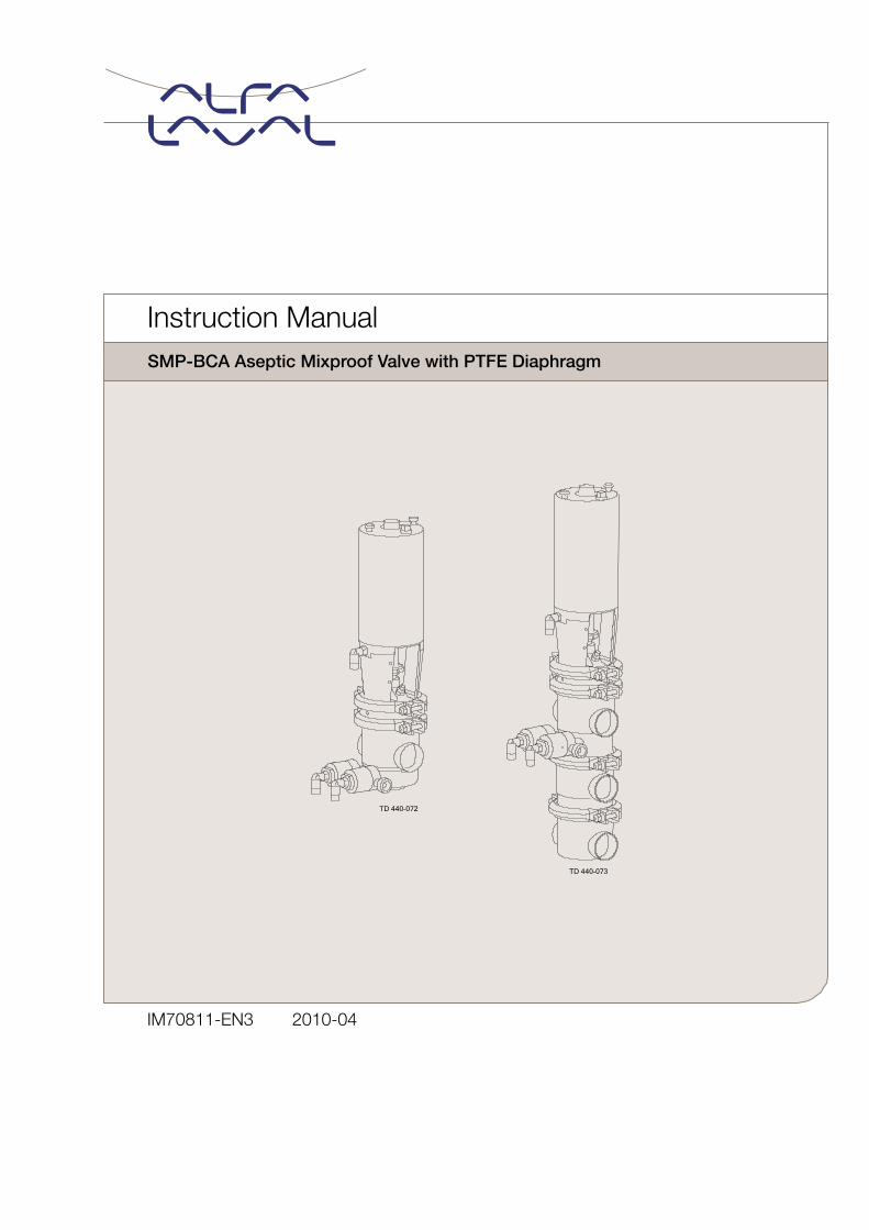
IM70811-EN3 2010-04
SMP-BCA Aseptic Mixproof Valve with PTFE Diaphragm
Instruction Manual

Alfa Laval Company Name
Bjarne Søndergaard
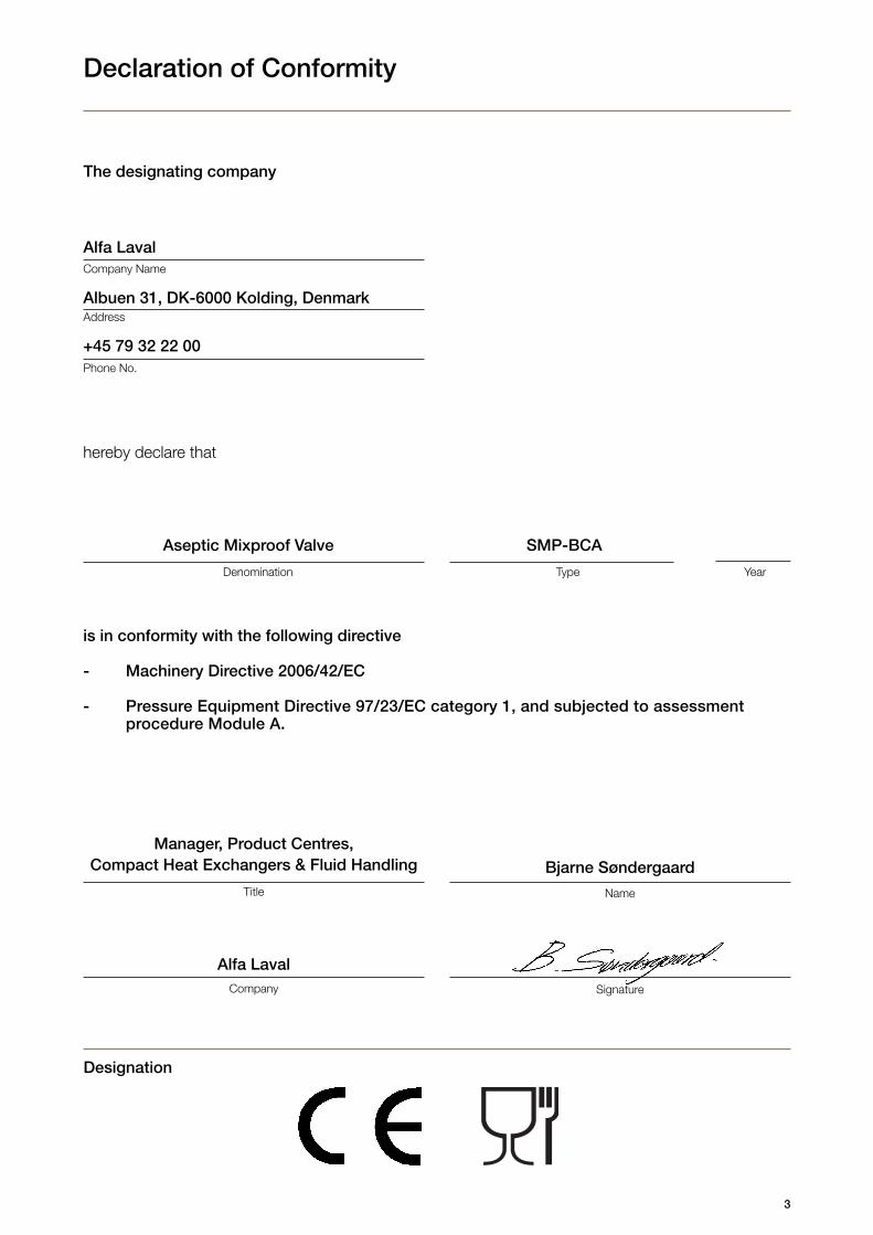
Declaration of Conformity
The designating company
Designation
is in conformity with the following directive
- Machinery Directive 2006/42/EC
- Pressure Equipment Directive 97/23/EC category 1, and subjected to assessment procedure Module A.
hereby declare that
Denomination Type Year
Address
Phone No.
NameTitle
Company Signature
Alfa Laval
Albuen 31, DK-6000 Kolding, Denmark
+45 79 32 22 00
Aseptic Mixproof Valve SMP-BCA
3
Manager, Product Centres,Compact Heat Exchangers & Fluid Handling

4

The information contained herein is correct at the time of issue but may be subject to change without prior notice.
5
Table of contents
1. Safety ..................................................................................................... 61.1 Important information ........................................................................ 61.2 Warning signs ................................................................................... 61.3 Safety precautions ............................................................................ 6
2. Installation ............................................................................................. 72.1 Unpacking/Delivery ........................................................................... 72.2 General installation ............................................................................ 92.3 Welding .......................................................................................... 11
3. Operation ............................................................................................. 133.1 Operation ........................................................................................ 133.2 Fault finding .................................................................................... 133.3 Recommended cleaning ................................................................. 143.4 Cleaning equipment (optional extra) ................................................ 17
4. Maintenance ........................................................................................ 184.1 General maintenance ...................................................................... 184.2 Dismantling of valve ........................................................................ 204.3 Assembly of valve ........................................................................... 224.4 Dismantling of actuator ................................................................... 254.5 Assembly of actuator ...................................................................... 264.6 Replacement of plug seals .............................................................. 28
5. Technical data ...................................................................................... 305.1 Technical data ................................................................................. 30
6. Parts list and service kits .................................................................... 326.1 Drawings ........................................................................................ 326.2 SMP-BCA stop valve ...................................................................... 346.3 SMP-BCA change-over valve .......................................................... 366.4 Tool for plug seals ........................................................................... 38
6
Unsafe practices and other important information are emphasized in this manual.Warnings are emphasized by means of special signs.All warnings in the manual are summarized on this page.Pay special attention to the instructions below so that severe personal injury and/or damage to the valve are avoided.
1.1 Important information1.2 Warning signs1.3 Safety precautions
1. Safety
WARNING!Indicates that special procedures must be followed to avoid severe personal injury.
CAUTION! Indicates that special procedures must be followed to avoid damage to the valve.
NOTE!Indicates important information to simplify practices or to make them clearer.
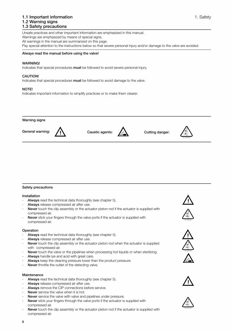
General warning:
Always read the manual before using the valve!
Caustic agents:
Warning signs
Safety precautions
Installation- Always read the technical data thoroughly (see chapter 5).- Always release compressed air after use.- Never touch the clip assembly or the actuator piston rod if the actuator is supplied with compressed air.- Never stick your fingers through the valve ports if the actuator is supplied with compressed air.
Operation- Always read the technical data thoroughly (see chapter 5).- Always release compressed air after use.- Never touch the clip assembly or the actuator piston rod when the actuator is supplied with compressed air.- Never touch the valve or the pipelines when processing hot liquids or when sterilizing.- Always handle lye and acid with great care.- Always keep the cleaning pressure lower than the product pressure.- Never throttle the outlet of the detecting valve.
Maintenance- Always read the technical data thoroughly (see chapter 5).- Always release compressed air after use.- Always remove the CIP connections before service.- Never service the valve when it is hot.- Never service the valve with valve and pipelines under pressure.- Never stick your fingers through the valve ports if the actuator is supplied with compressed air.- Never touch the clip assembly or the actuator piston rod if the actuator is supplied with compressed air.
Cutting danger:

7
The instruction manual is part of the delivery.Study the instructions carefully.Stop valve: With one valve body. Change-over valve: With three valve bodies.CIP = Cleaning In Place (see section 3.3).
Inspection!
Caution!
Remove packing materials!
2. Installation 2.1 Unpacking/Delivery
Step 1CAUTION!Alfa Laval cannot be held responsible for incorrect unpacking.
Check the delivery for:1. Complete valve, standard or three-bodied valve.2. Delivery note.3. Instruction manual.
Step 2Remove possible packing materials from the valve ports.Avoid damaging the air connection and the valve ports, the detecting valve and the CIP valve.,
Step 3Inspect the valve for visible transport damage.
8
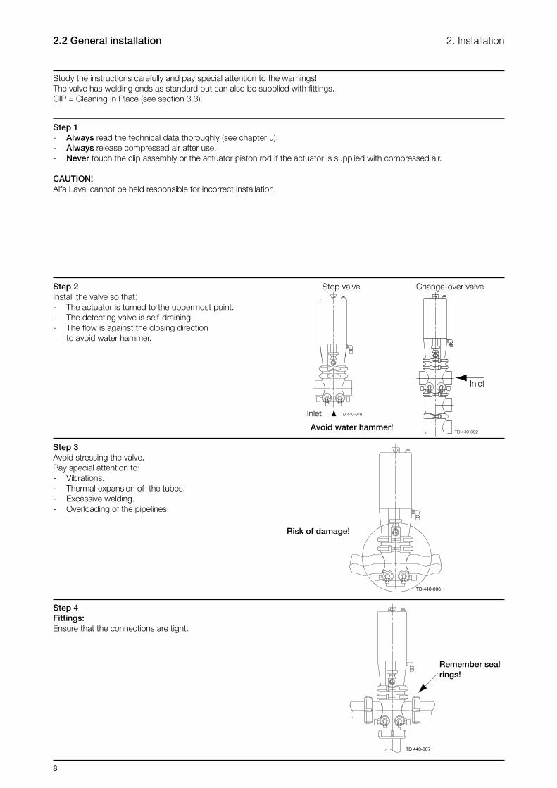
2. Installation2.2 General installation
Study the instructions carefully and pay special attention to the warnings!The valve has welding ends as standard but can also be supplied with fittings.CIP = Cleaning In Place (see section 3.3).
Risk of damage!
Stop valve
Inlet
Change-over valve
Inlet
Remember seal rings!
Avoid water hammer!
Step 1- Always read the technical data thoroughly (see chapter 5).- Always release compressed air after use.- Never touch the clip assembly or the actuator piston rod if the actuator is supplied with compressed air.
CAUTION!Alfa Laval cannot be held responsible for incorrect installation.
Step 2Install the valve so that:- The actuator is turned to the uppermost point.- The detecting valve is self-draining.- The flow is against the closing direction to avoid water hammer.
Step 3Avoid stressing the valve.Pay special attention to:- Vibrations.- Thermal expansion of the tubes.- Excessive welding.- Overloading of the pipelines.
Step 4Fittings:Ensure that the connections are tight.
9
2. Installation
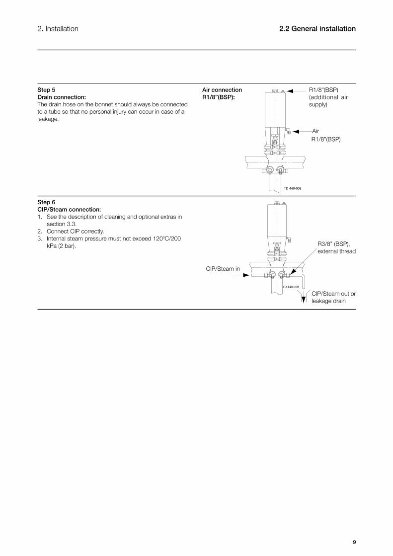
Step 6CIP/Steam connection:1. See the description of cleaning and optional extras in section 3.3. 2. Connect CIP correctly.3. Internal steam pressure must not exceed 1200C/200 kPa (2 bar).
Step 5Drain connection:The drain hose on the bonnet should always be connected to a tube so that no personal injury can occur in case of a leakage.
R1/8”(BSP)(additional air supply)
R1/8”(BSP) Air
R3/8” (BSP), external thread
CIP/Steam out or leakage drain
CIP/Steam in
Air connectionR1/8”(BSP):
2.2 General installation
10
2. Installation
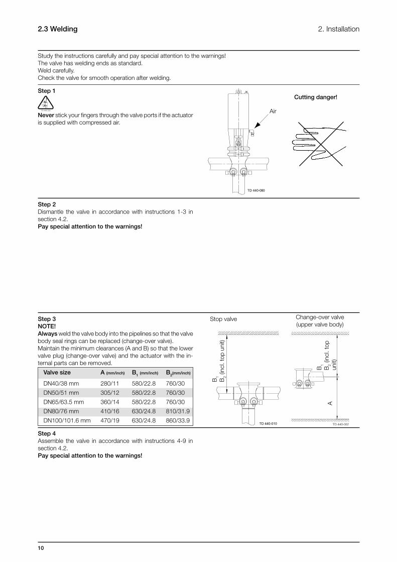
Study the instructions carefully and pay special attention to the warnings!The valve has welding ends as standard.Weld carefully.Check the valve for smooth operation after welding.
Cutting danger!
Stop valve
Air
B1
B2
(incl
. top
uni
t)
B1
B2
(incl
. top
un
it)
Change-over valve (upper valve body)
A
Step 1
Never stick your fingers through the valve ports if the actuator is supplied with compressed air.
Step 2Dismantle the valve in accordance with instructions 1-3 in section 4.2. Pay special attention to the warnings!
Step 3NOTE! Always weld the valve body into the pipelines so that the valve body seal rings can be replaced (change-over valve).Maintain the minimum clearances (A and B) so that the lower valve plug (change-over valve) and the actuator with the in-ternal parts can be removed.
Step 4Assemble the valve in accordance with instructions 4-9 in section 4.2.Pay special attention to the warnings!
2.3 Welding
Valve size A (mm/inch) B1 (mm/inch) B2(mm/inch)
DN40/38 mm 280/11 580/22.8 760/30
DN50/51 mm 305/12 580/22.8 760/30
DN65/63.5 mm 360/14 580/22.8 760/30
DN80/76 mm 410/16 630/24.8 810/31.9
DN100/101.6 mm 470/19 630/24.8 860/33.9

11
2. Installation 2.3 Welding
Air Open/close!
Step 5Pre-use check:1. Supply compressed air to the actuator.2. Open and close the valve a few times to ensure that it operates smoothly.Pay special attention to the warnings!
12
Problem
Product leakage through the detecting valve (closed valve)
Product leakage through the detecting valve (open valve)
Product leakage at drain tube and/or clamp
Product leakage through middleor lower valve body (closed lowerplug)
- Air leakage through the CIP and detecting valve- Air leakage at the actuator
Cause/result
- Worn seal rings - The two seal rings affected by different products - Incorrect fitting of seal rings- Product deposits on the seat and/or plug
- Worn O-ring (26a)- Worn spindle (26d)- Product deposits on the seat and/or plug
Worn/product affected diaphragm set (22) and/or seal rings (17)
- Worn/product affected plug seal
ring- Loose parts (vibrations)- Product deposits on the seat and/ or plug
Worn seal rings
Possible solution
- Replace the seal rings- Select a different rubber grade- Frequent cleaning
- Replace the O-ring- Replace the spindle - Frequent cleaning
- Replace the seal rings or diaphragm set- Select a different rubber grade
- Replace the seal ring- Select a different rubber grade- Tighten the loose parts- Frequent cleaning
Replace the seal rings
The valve is adjusted and tested before delivery.Study the instructions carefully and pay special attention to the warnings! Pay attention to possible faults.The items refer to the drawings and parts list in chapter 6.CIP = Cleaning In Place (see section 3.3).
Step 1
Burning danger!
3. Operation3.1 Operation3.2 Fault finding
- Always read the technical data thoroughly (see chapter 5).- Always release compressed air after use.- Never touch the clip assembly or the actuator piston rod when the actuator is supplied with compressed air.
CAUTION!Alfa Laval cannot be held responsible for incorrect operation.
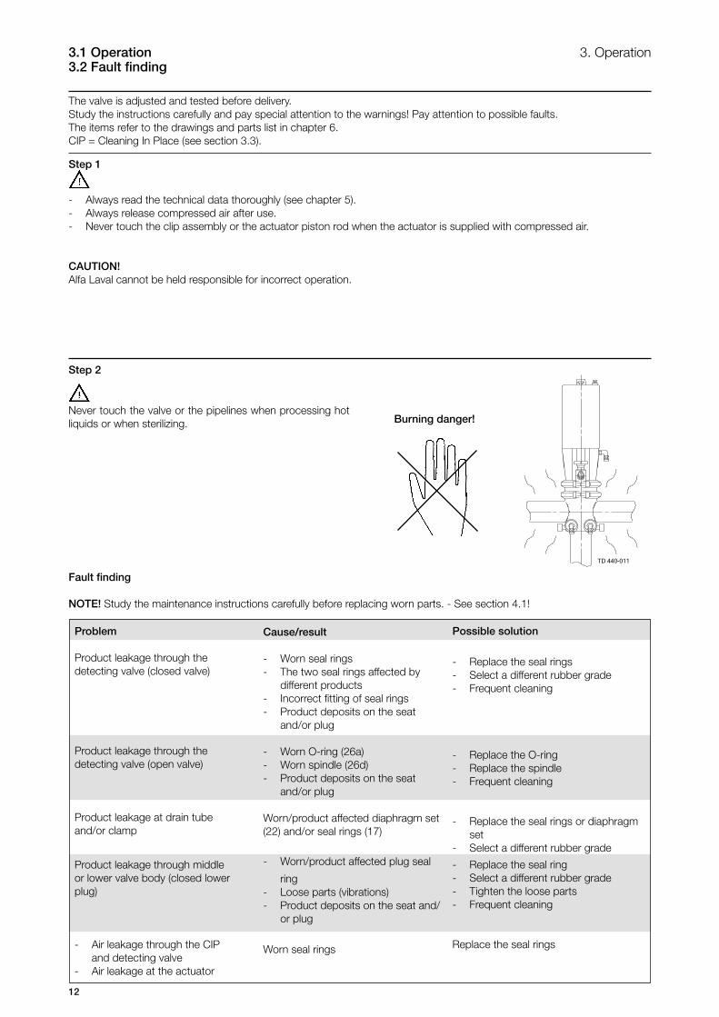
Step 2
Fault finding
NOTE! Study the maintenance instructions carefully before replacing worn parts. - See section 4.1!
Never touch the valve or the pipelines when processing hot liquids or when sterilizing.
13
3. Operation 3.3 Recommended cleaning
Step 4Examples of cleaning agents:Use clean water, free from chlorides.
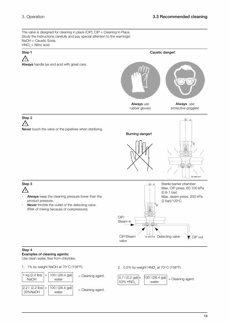
1. 1% by weight NaOH at 70o C (158°F).
The valve is designed for cleaning in place (CIP). CIP = Cleaning In Place.Study the instructions carefully and pay special attention to the warnings!NaOH = Caustic Soda. HNO3 = Nitric acid.
Step 1 Caustic danger!
Always use rubber gloves!
Always use protective goggles!
2. 0.5% by weight HNO3 at 70o C (158°F).
= Cleaning agent.
= Cleaning agent.
= Cleaning agent.
Never touch the valve or the pipelines when sterilizing.
Step 3
Step 2
Sterile barrier chamber:Max. CIP press. 60-100 kPa (0.6-1 bar)Max. steam press. 200 kPa (2 bar)/120oC
CIP/Steam in
Detecting valveCIP/Steam valve
CIP out
Always handle lye and acid with great care.
- Always keep the cleaning pressure lower than the product pressure.- Never throttle the outlet of the detecting valve. (Risk of mixing because of overpressure).
1 kg (2.2 lbs) + 100 l (26.4 gal) NaOH water
2.2 l (2.2 lbs) + 100 l (26.4 gal) 33%NaOH water
0.7 l (0.2 gal) + 100 l (26.4 gal) 53% HNO3 water
Burning danger!
14
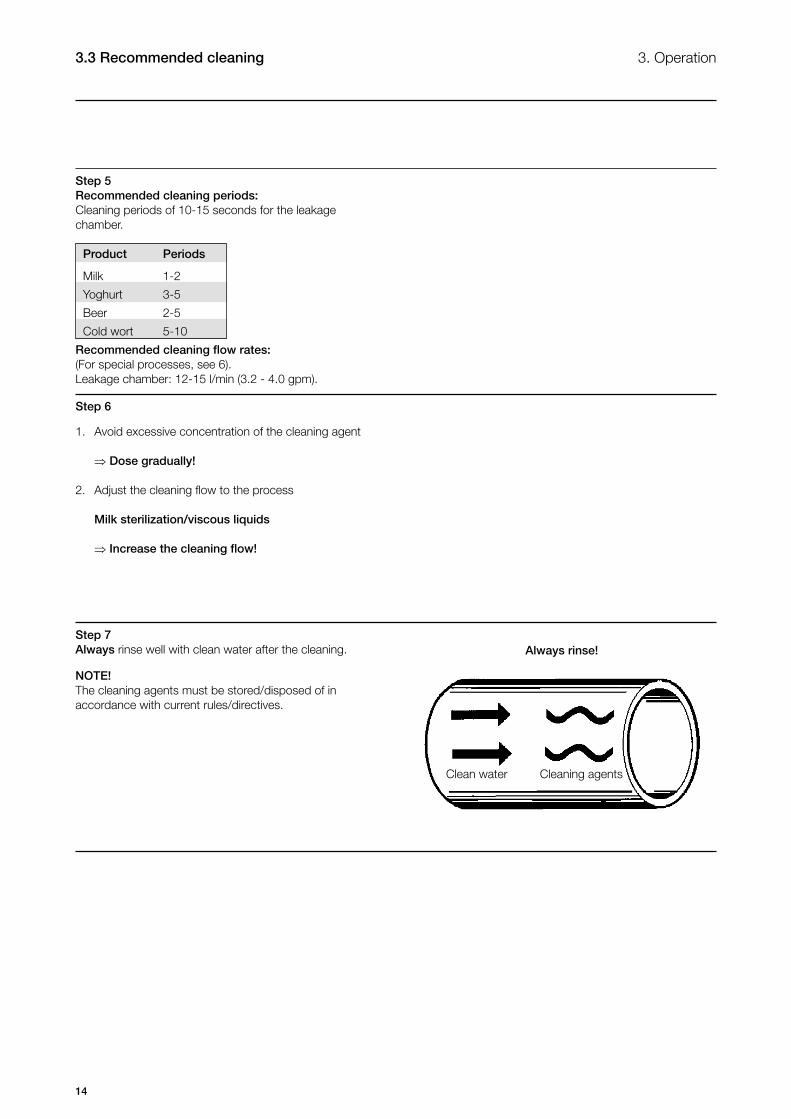
Always rinse!
Clean water Cleaning agents
Step 5Recommended cleaning periods:Cleaning periods of 10-15 seconds for the leakage chamber.
Product Periods
Milk 1-2
Yoghurt 3-5
Beer 2-5
Cold wort 5-10
Recommended cleaning flow rates:(For special processes, see 6).Leakage chamber: 12-15 l/min (3.2 - 4.0 gpm).
1. Avoid excessive concentration of the cleaning agent
⇒ Dose gradually!
2. Adjust the cleaning flow to the process
Milk sterilization/viscous liquids
⇒ Increase the cleaning flow!
Step 6
3. Operation3.3 Recommended cleaning
Step 7Always rinse well with clean water after the cleaning.
NOTE!The cleaning agents must be stored/disposed of in accordance with current rules/directives.

15
3. Operation 3.3 Recommended cleaning
Product
CIP
Product
CIP
Cleaning cycle:Pay special attention to the warnings!
Closed Stop valve:Cleaning of sterile barrier chamber
Open Stop valve:Cleaning of the valve body and the leakage chamber
CIP/Steam in CIP/Steam out
Change-over valve:Cleaning of the upper valve body

16
3. Operation3.4 Cleaning and sterilization equipment (optional extra)
The installations kits are for cleaning/sterilizing of the leakage chamber when the valve is closed.The stainless steel tubes must be cut and welded during installation.CIP = Cleaning In Place.
Contents:Pos. 1 Welding male partPos. 4 CIP leakage tube AISI 316
* Adjust and weld during installation.
Step 2To ensure aseptic processing and mixproof function certain rules must be followed:
- After the valve is closed the leakage chamber must be cleaned and sterilized.- The leakage chamber must be kept sterile until the valve is opened again.
Step 1Installation kit C for CIP/steam and leakage connection of a single valve (stainless steel tubes).
17
Maintain the valve regularly.Study the instructions carefully and pay special attention to the warnings!CIP = Cleaning In Place.Always keep spare rubber seals, lip seals and guide rings in stock.
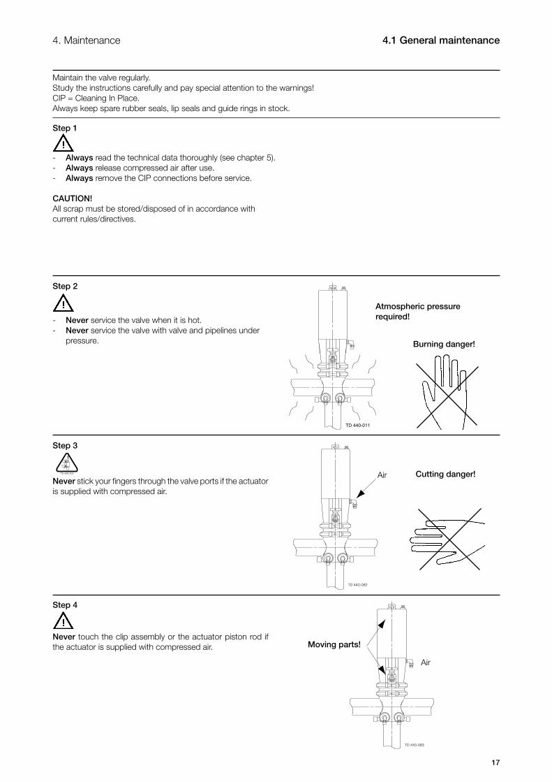
Atmospheric pressure required!
Burning danger!
Cutting danger!Air
Air
Moving parts!
4. Maintenance 4.1 General maintenance
Step 1
Step 2
Step 3
Step 4
- Always read the technical data thoroughly (see chapter 5).- Always release compressed air after use.- Always remove the CIP connections before service.
CAUTION!All scrap must be stored/disposed of in accordance with current rules/directives.
- Never service the valve when it is hot.- Never service the valve with valve and pipelines under pressure.
Never stick your fingers through the valve ports if the actuator is supplied with compressed air.
Never touch the clip assembly or the actuator piston rod if the actuator is supplied with compressed air.
18
Ordering spare parts
- Contact the Sales Department.- Order from the Spare Parts List.
Recommended spare parts: Service kits (see Spare Parts List).
The valve is designed so that single internal leakages do not result in the products becoming mixed.Internal leakage in the valve is externally visible.Study the instructions carefully.Always keep spare rubber seals, lip seals and guide rings in stock. Check the valve for smooth operation after service.
Preventive maintenance
Maintenance after leakage (leakage normally starts slowly)
Planned maintenance
Lubrication (USDAH1approved oil/grease)
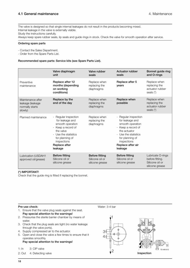
Pre-use check:1. Ensure that the valve plug seals against the seat. Pay special attention to the warnings!2. Pressurise the sterile barrier chamber by means of water.3. Check that the plug seals are tight (no water leakage through the valve ports).4. Supply compressed air to the actuator.5. Open and close the valve a few times to ensure that it operates smoothly. Pay special attention to the warnings!
1: In 3: CIP valve
2: Out 4: Detecting valve
Valve diaphragmunit
Replace after 12months (depending on working conditions)
Replace by the end of the day
- Regular inspection for leakage and smooth operation- Keep a record of the valve- Use the statistics for planning of inspectionsReplace after leakage
Before fittingSilicone oil or silicone grease
Valve rubber seals
Replace when replacing thediaphragms
Replace when replacing thediaphragms
Replace when replacing the diaphragms
Before fittingSilicone oil or silicone grease
Actuator rubber seals
Replace after 5 years
Replace when possible
- Regular inspection for leakage and smooth operation- Keep a record of the actuator- Use the statistics for planning of inspectionsReplace after air leakage
Before fittingSilicone oil or silicone grease
Bonnet guide ring and O-rings
Replace whenreplacing the actuator rubber seals (*)
Replace when replacing the actuator rubber seals (*)
Lubricate O-rings before fitting.Silicone oil or silicone grease
4. Maintenance4.1 General maintenance
Water: 3-4 bar
Inspection
(*) IMPORTANT!Check that the guide ring is fitted if replacing the bonnet.
19
Study the instructions carefully.The items refer to the drawings and the parts list in chapter 6.Lubricate the rubber seals and the diaphragms before fitting them.
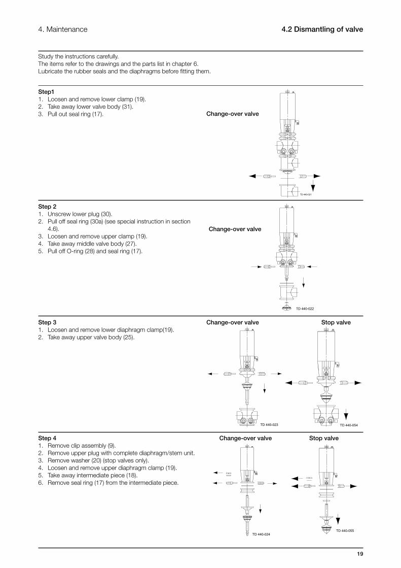
4. Maintenance 4.2 Dismantling of valve
Change-over valve Stop valve
Change-over valve Stop valve
Step 41. Remove clip assembly (9).2. Remove upper plug with complete diaphragm/stem unit.3. Remove washer (20) (stop valves only).4. Loosen and remove upper diaphragm clamp (19).5. Take away intermediate piece (18).6. Remove seal ring (17) from the intermediate piece.
Step 31. Loosen and remove lower diaphragm clamp(19).2. Take away upper valve body (25).
Step11. Loosen and remove lower clamp (19).2. Take away lower valve body (31).3. Pull out seal ring (17).
Step 21. Unscrew lower plug (30).2. Pull off seal ring (30a) (see special instruction in section 4.6).3. Loosen and remove upper clamp (19).4. Take away middle valve body (27).5. Pull off O-ring (28) and seal ring (17).
Change-over valve
Change-over valve

20
4. Maintenance4.2 Dismantling of valve
Step 61. Remove air fitting (26g).2. Unscrew CIP valve housing (26f).3. Pull out CIP valve plug (26d).4. Remove CIP valve spring (26b).
Step 51. In sequence, turn lower and upper stem (29,21) anticlockwise (for stop valve: only upper stem) to separate them from upper plug (24) (counterhold with a spanner).2. Remove diaphragms (22a, 22b), L-seal (22c) and stem seal (22d) from the upper plug.3. Remove diaphragm ring (23) and seal ring (17) from upper valve plug (25) (only for valve sizes 76-101.6mm/ DN80-100).
21
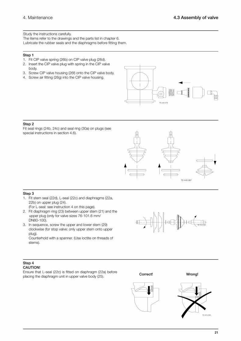
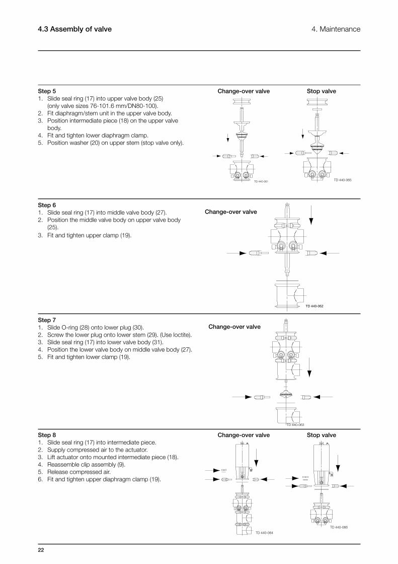
4. Maintenance 4.3 Assembly of valve
Study the instructions carefully.The items refer to the drawings and the parts list in chapter 6.Lubricate the rubber seals and the diaphragms before fitting them.
Correct! Wrong!
Step 11. Fit CIP valve spring (26b) on CIP valve plug (26d).2. Insert the CIP valve plug with spring in the CIP valve body.3. Screw CIP valve housing (26f) onto the CIP valve body.4. Screw air fitting (26g) into the CIP valve housing.
Step 2Fit seal rings (24b, 24c) and seal ring (30a) on plugs (see special instructions in section 4.6).
Step 31. Fit stem seal (22d), L-seal (22c) and diaphragms (22a, 22b) on upper plug (24). (For L-seal: see instruction 4 on this page).2. Fit diaphragm ring (23) between upper stem (21) and the upper plug (only for valve sizes 76-101.6 mm/ DN80-100).3. In sequence, screw the upper and lower stem (29) clockwise (for stop valve: only upper stem onto upper plug). Counterhold with a spanner. (Use loctite on threads of stems).
Step 4CAUTION!Ensure that L-seal (22c) is fitted on diaphragm (22a) before placing the diaphragm unit in upper valve body (25).
22
4. Maintenance4.3 Assembly of valve
Step 61. Slide seal ring (17) into middle valve body (27).2. Position the middle valve body on upper valve body (25).3. Fit and tighten upper clamp (19).
Step 51. Slide seal ring (17) into upper valve body (25) (only valve sizes 76-101.6 mm/DN80-100).2. Fit diaphragm/stem unit in the upper valve body.3. Position intermediate piece (18) on the upper valve body.4. Fit and tighten lower diaphragm clamp.5. Position washer (20) on upper stem (stop valve only).
Change-over valve Stop valve
Change-over valve
Step 71. Slide O-ring (28) onto lower plug (30).2. Screw the lower plug onto lower stem (29). (Use loctite).3. Slide seal ring (17) into lower valve body (31).4. Position the lower valve body on middle valve body (27).5. Fit and tighten lower clamp (19).
Step 81. Slide seal ring (17) into intermediate piece.2. Supply compressed air to the actuator.3. Lift actuator onto mounted intermediate piece (18).4. Reassemble clip assembly (9).5. Release compressed air.6. Fit and tighten upper diaphragm clamp (19).
Change-over valve
Change-over valve Stop valve

23
4. Maintenance 4.3 Assembly of valve
Air Open/close!
Step 91. Supply compressed air to the actuator.2. Operate the valve a few times to ensure that it runs smoothly. Pay special attention to the warnings.
24
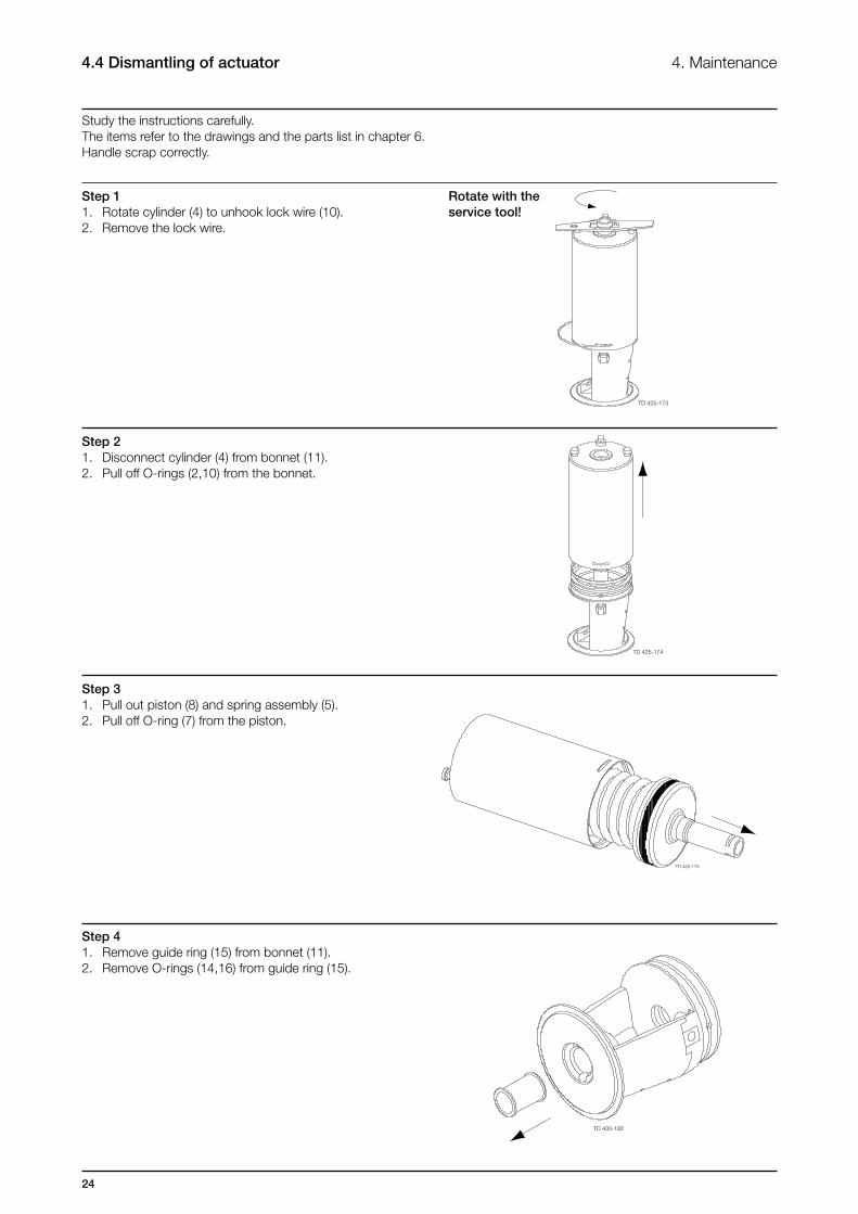
4. Maintenance4.4 Dismantling of actuator
Study the instructions carefully.The items refer to the drawings and the parts list in chapter 6.Handle scrap correctly.
Step 11. Rotate cylinder (4) to unhook lock wire (10).2. Remove the lock wire.
Step 21. Disconnect cylinder (4) from bonnet (11).2. Pull off O-rings (2,10) from the bonnet.
Step 31. Pull out piston (8) and spring assembly (5).2. Pull off O-ring (7) from the piston.
Step 41. Remove guide ring (15) from bonnet (11).2. Remove O-rings (14,16) from guide ring (15).
Rotate with the service tool!
25
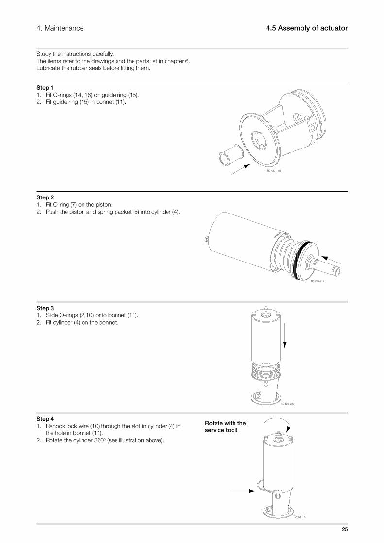
Study the instructions carefully.The items refer to the drawings and the parts list in chapter 6.Lubricate the rubber seals before fitting them.
Rotate with the service tool!
4. Maintenance 4.5 Assembly of actuator
Step 11. Fit O-rings (14, 16) on guide ring (15).2. Fit guide ring (15) in bonnet (11).
Step 21. Fit O-ring (7) on the piston.2. Push the piston and spring packet (5) into cylinder (4).
Step 31. Slide O-rings (2,10) onto bonnet (11).2. Fit cylinder (4) on the bonnet.
Step 41. Rehook lock wire (10) through the slot in cylinder (4) in the hole in bonnet (11).2. Rotate the cylinder 360o (see illustration above).

26
Bottom air connection
Top air connection
4. Maintenance4.5 Assembly of actuator
Step 5NOTE!Rotate cylinder (4) further 180o in relation to bonnet (11) so that the top and bottom air connections are fixed on the same side.
27
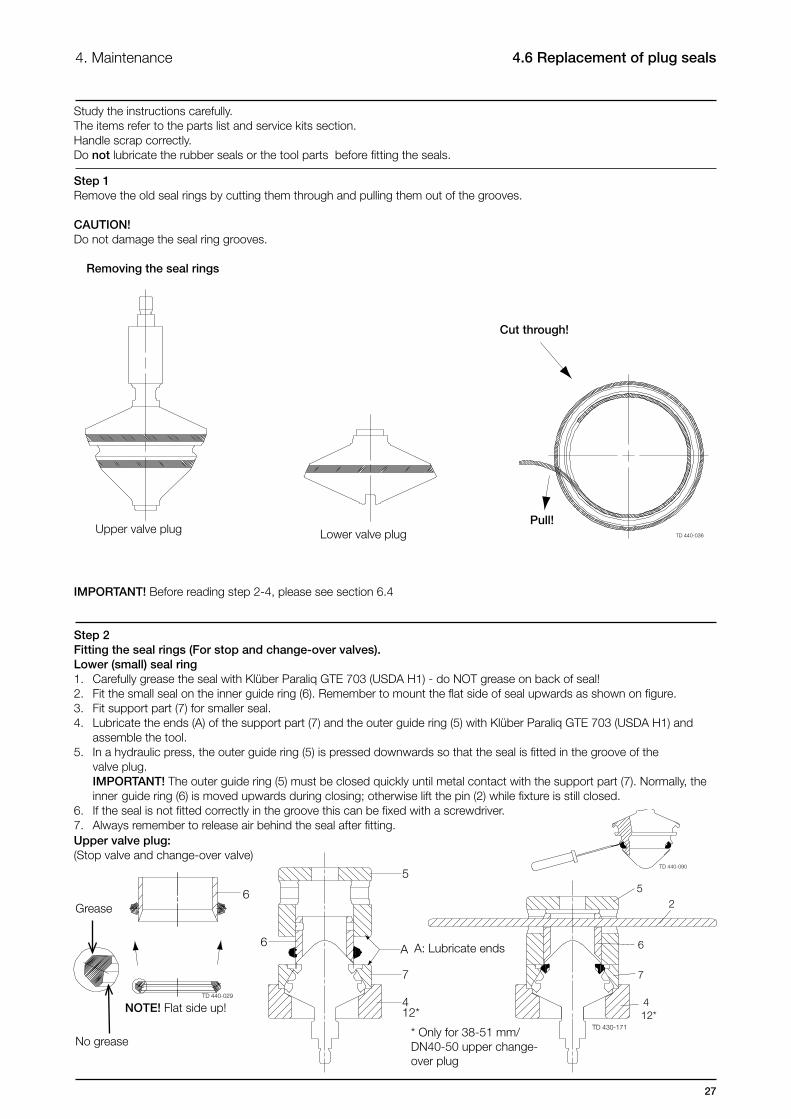
Step 1Remove the old seal rings by cutting them through and pulling them out of the grooves.
CAUTION!Do not damage the seal ring grooves.
4. Maintenance 4.6 Replacement of plug seals
Upper valve plug
Removing the seal rings
Lower valve plug
Cut through!
Pull!
Step 2Fitting the seal rings (For stop and change-over valves).Lower (small) seal ring1. Carefully grease the seal with Klüber Paraliq GTE 703 (USDA H1) - do NOT grease on back of seal!2. Fit the small seal on the inner guide ring (6). Remember to mount the flat side of seal upwards as shown on figure.3. Fit support part (7) for smaller seal.4. Lubricate the ends (A) of the support part (7) and the outer guide ring (5) with Klüber Paraliq GTE 703 (USDA H1) and assemble the tool.5. In a hydraulic press, the outer guide ring (5) is pressed downwards so that the seal is fitted in the groove of the valve plug. IMPORTANT! The outer guide ring (5) must be closed quickly until metal contact with the support part (7). Normally, the inner guide ring (6) is moved upwards during closing; otherwise lift the pin (2) while fixture is still closed.6. If the seal is not fitted correctly in the groove this can be fixed with a screwdriver.7. Always remember to release air behind the seal after fitting.
* Only for 38-51 mm/ DN40-50 upper change-over plug
IMPORTANT! Before reading step 2-4, please see section 6.4
A: Lubricate ends
Study the instructions carefully.The items refer to the parts list and service kits section.Handle scrap correctly.Do not lubricate the rubber seals or the tool parts before fitting the seals.
Upper valve plug:(Stop valve and change-over valve)
NOTE! Flat side up!
Grease
No grease

28
A: Lubricate ends
4. Maintenance4.6 Replacement of plug seals
Step 3Fitting the seal rings (For stop and change-over valves)Upper (large) seal ring:1. Carefully grease the seal with Klüber Paraliq GTE 703 (USDA H1) - Do NOT grease on back of seal!2. Fit the large seal on the inner guide ring (3). Remember to mount the flat side of seal upwards as shown on figure.3. Lubricate the ends (A) of the tool housing (4) and the outer guide ring (1) with Klüber Paraliq GTE 703 (USDA H1) and assemble the tool.5. In a hydraulic press, the outer guide ring (1) is pressed downwards so that the seal is fitted in the groove of the valve plug. IMPORTANT! The outer guide ring (1) must be closed quickly until metal contact with the tool housing (4). Normally, the inner guide ring (3) is moved upwards during closing; otherwise lift the pin (2) while fixture is still closed.6. If the seal is not fitted correctly in the groove this can be fixed with a screwdriver.7. Always remember to release air behind the seal after fitting.
* Only for 38-51 mm/DN40-50 upper change-over plug
A: Lubricate ends
NOTE! Flat side up!
Grease
No grease
NOTE! Flat side up!
Grease
No grease
Step 4Fitting the seal rings (For change-over valves)1. Carefully grease the seal with Klüber Paraliq GTE 703 (USDA H1) - Do NOT grease on back of seal!2. Fit the seal on the inner guide ring (9). Remember to mount the flat side of seal upwards as shown on figure.3. Fit support part (10)4. Lubricate the ends of the support part (10) and the outer guide ring (8) with Klüber Paraliq GTE 703 (USDA H1) and assemble the tool.5. In a hydraulic press, the outer guide ring (8) is pressed downwards so that the seal is fitted in the groove of the valve plug. IMPORTANT! The outer guide ring (8) must be closed quickly until metal contact with the support part (10). Normally, the inner guide ring (9) is moved upwards during closing; otherwise lift the pin (2) while fixture is still closed.6. If the seal is not fitted correctly in the groove this can be fixed with a screwdriver.7. Always remember to release air behind the seal after fitting.
Upper valve plug:(Stop valve and change-over valve)
Lower valve plug:(Change-over valve)

29
It is important to observe the technical data during installation, operation and maintenance.Inform the personnel about the technical data.
5. Technical data 5.1 Technical data
Technical data Pressure range 0 - 800 kPa (0-8 bar) Temperature range -10°C to 140°C (EPDM) Optimum process conditions >50 kPa (0,5 bar), > 20°C Max. sterilisation temperature (steam – short time) 150°C – 380kPa (3,8 bar) Air pressure 500 – 800 kPa (5-8 bar) Air consumption (litres free air) 38mm, 51mm, DN40, DN50 0,2 x air pressure in bar 63,5mm, 76mm, 101,6mm, DN65, DN 80, DN100 0,7 x air pressure in bar NOTE! Vacuum is not recommended in aseptic applications.
Expected lifetime of diaphragm unit under normal conditions: (no pressure shocks or cavitation)
Size/Type Stop valve Change over valve activations activitations 38mm/DN40 12.000 10.000 51mm/DN50 12.000 10.000 63,5mm/DN65 12.000 5.000 76,1mm/DN80 5.000 5.000 101mm/DN100 5.000 5.000
NOTE! Activating the valve without internal product pressure reduces lifetime of diaphragm unit.
Materials
Product wetted steel parts Acid resistant steel AISI 316L Other steel parts Stainless steel AISI 304 Finish Semi bright Product wetted seals EPDM, PTFE Other seals NBR, EPDM
30
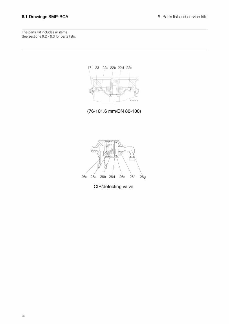
(76-101.6 mm/DN 80-100)
CIP/detecting valve
6.1 Drawings SMP-BCA
The parts list includes all items.See sections 6.2 - 6.3 for parts lists.
6. Parts list and service kits
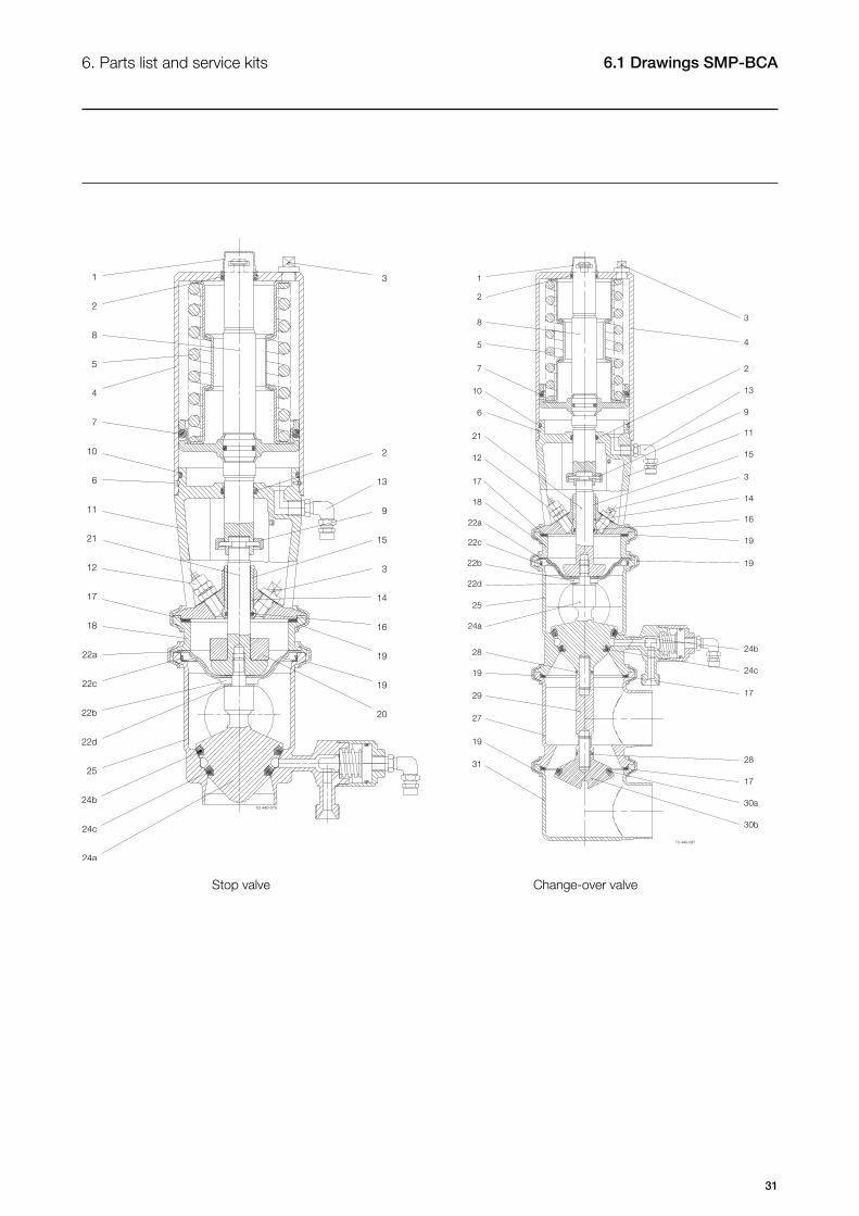
31
6. Parts list and service kits 6.1 Drawings SMP-BCA
Stop valve Change-over valve
32
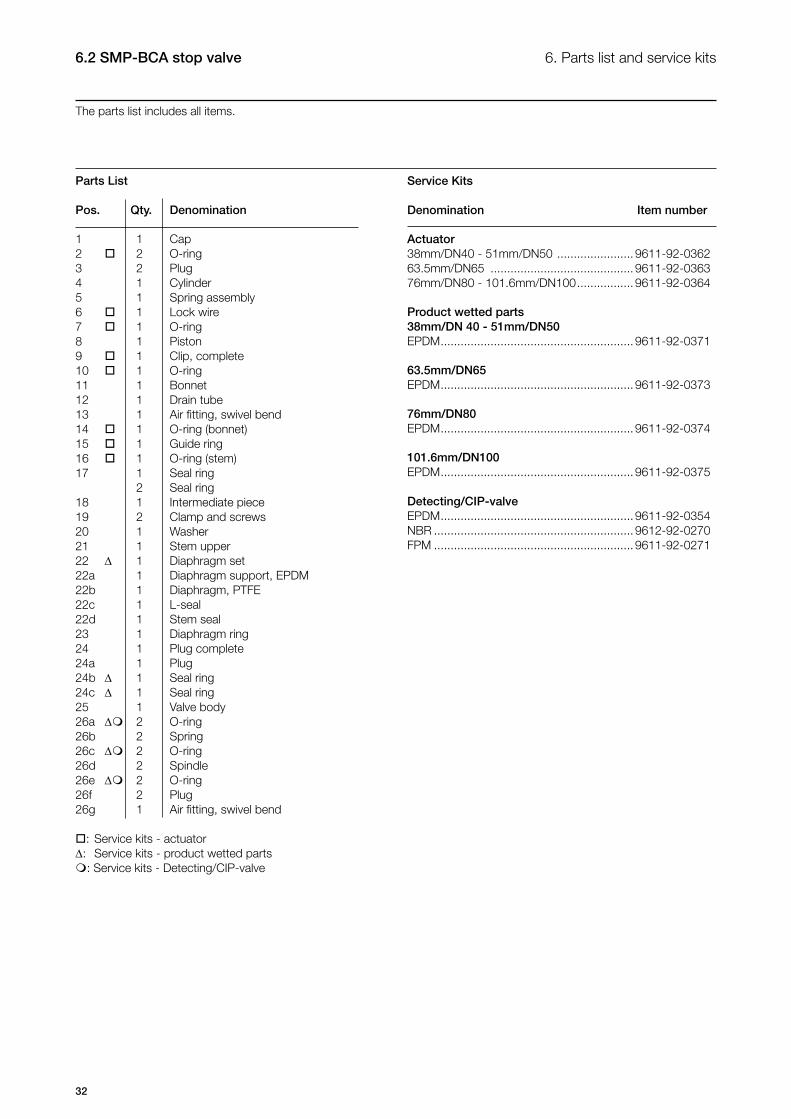
6. Parts list and service kits6.2 SMP-BCA stop valve
The parts list includes all items.
Service Kits
Denomination Item number
Actuator38mm/DN40 - 51mm/DN50 ....................... 9611-92-036263.5mm/DN65 ........................................... 9611-92-036376mm/DN80 - 101.6mm/DN100 ................. 9611-92-0364 Product wetted parts38mm/DN 40 - 51mm/DN50EPDM .......................................................... 9611-92-0371
63.5mm/DN65EPDM .......................................................... 9611-92-0373
76mm/DN80EPDM .......................................................... 9611-92-0374
101.6mm/DN100EPDM .......................................................... 9611-92-0375
Detecting/CIP-valveEPDM .......................................................... 9611-92-0354NBR ............................................................ 9612-92-0270FPM ............................................................ 9611-92-0271
Parts List
Pos. Qty. Denomination
1 1 Cap2 2 O-ring3 2 Plug4 1 Cylinder5 1 Spring assembly6 1 Lock wire7 1 O-ring8 1 Piston9 1 Clip, complete10 1 O-ring11 1 Bonnet12 1 Drain tube13 1 Air fitting, swivel bend14 1 O-ring (bonnet)15 1 Guide ring16 1 O-ring (stem)17 1 Seal ring 2 Seal ring18 1 Intermediate piece19 2 Clamp and screws 20 1 Washer21 1 Stem upper22 ∆ 1 Diaphragm set22a 1 Diaphragm support, EPDM22b 1 Diaphragm, PTFE22c 1 L-seal22d 1 Stem seal23 1 Diaphragm ring 24 1 Plug complete24a 1 Plug24b ∆ 1 Seal ring24c ∆ 1 Seal ring25 1 Valve body26a ∆ 2 O-ring26b 2 Spring26c ∆ 2 O-ring26d 2 Spindle26e ∆ 2 O-ring26f 2 Plug26g 1 Air fitting, swivel bend
: Service kits - actuator∆: Service kits - product wetted parts: Service kits - Detecting/CIP-valve

33
6. Parts list and service kits 6.2 SMP-BCA stop valve
34
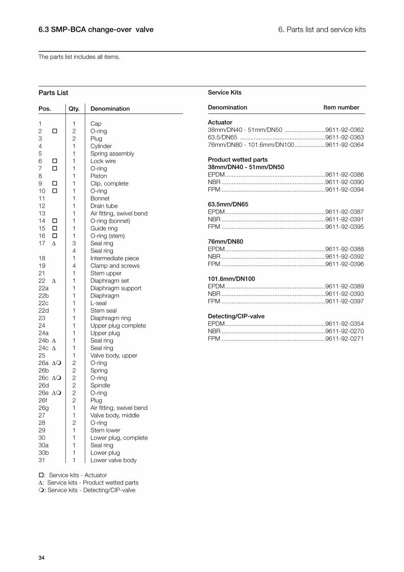
6. Parts list and service kits6.3 SMP-BCA change-over valve
The parts list includes all items.
Service Kits
Denomination Item number
Actuator38mm/DN40 - 51mm/DN50 ........................9611-92-036263.5/DN65 ..................................................9611-92-036376mm/DN80 - 101.6mm/DN100 ..................9611-92-0364
Product wetted parts38mm/DN40 - 51mm/DN50EPDM ...........................................................9611-92-0386NBR .............................................................9611-92-0390FPM .............................................................9611-92-0394
63.5mm/DN65EPDM ...........................................................9611-92-0387NBR .............................................................9611-92-0391FPM .............................................................9611-92-0395
76mm/DN80EPDM ...........................................................9611-92-0388NBR .............................................................9611-92-0392FPM .............................................................9611-92-0396
101.6mm/DN100EPDM ...........................................................9611-92-0389NBR .............................................................9611-92-0393FPM .............................................................9611-92-0397
Detecting/CIP-valveEPDM ...........................................................9611-92-0354NBR .............................................................9611-92-0270FPM .............................................................9611-92-0271
Parts List
Pos. Qty. Denomination
1 1 Cap2 2 O-ring3 2 Plug4 1 Cylinder5 1 Spring assembly6 1 Lock wire7 1 O-ring8 1 Piston9 1 Clip, complete10 1 O-ring11 1 Bonnet12 1 Drain tube13 1 Air fitting, swivel bend14 1 O-ring (bonnet)15 1 Guide ring16 1 O-ring (stem)17 ∆ 3 Seal ring 4 Seal ring18 1 Intermediate piece19 4 Clamp and screws 21 1 Stem upper22 ∆ 1 Diaphragm set22a 1 Diaphragm support22b 1 Diaphragm22c 1 L-seal22d 1 Stem seal23 1 Diaphragm ring 24 1 Upper plug complete24a 1 Upper plug24b ∆ 1 Seal ring24c ∆ 1 Seal ring25 1 Valve body, upper26a ∆ 2 O-ring26b 2 Spring26c ∆ 2 O-ring26d 2 Spindle26e ∆ 2 O-ring26f 2 Plug26g 1 Air fitting, swivel bend27 1 Valve body, middle28 2 O-ring29 1 Stem lower30 1 Lower plug, complete30a 1 Seal ring30b 1 Lower plug31 1 Lower valve body
: Service kits - Actuator∆: Service kits - Product wetted parts: Service kits - Detecting/CIP-valve
35
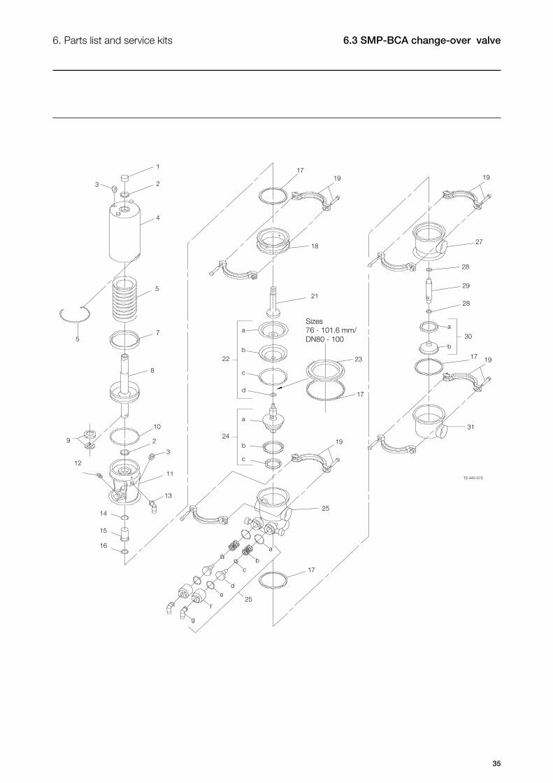
6. Parts list and service kits 6.3 SMP-BCA change-over valve
36
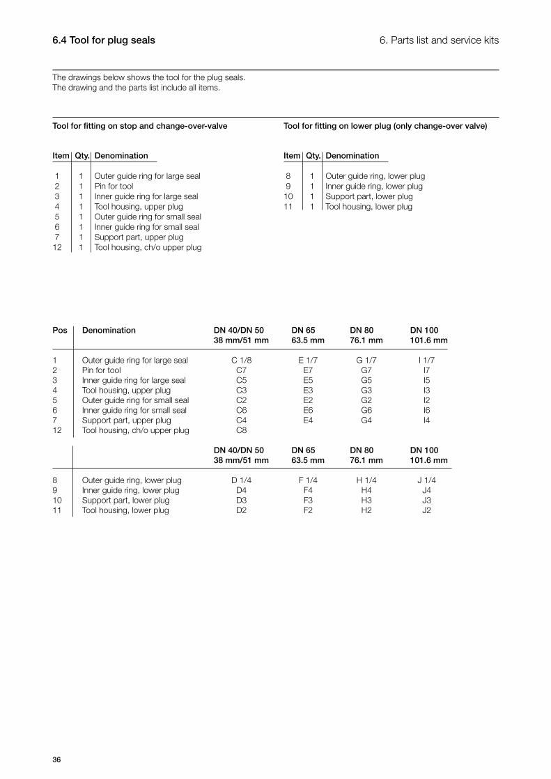
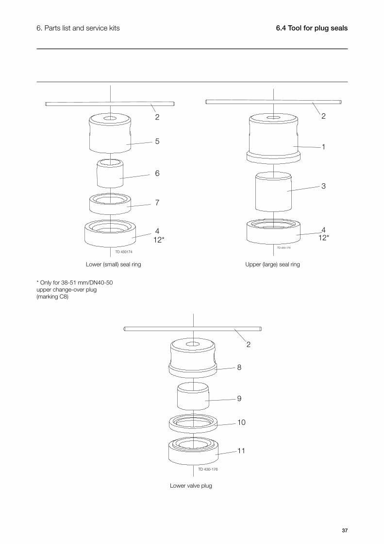
6.4 Tool for plug seals
The drawings below shows the tool for the plug seals.The drawing and the parts list include all items.
6. Parts list and service kits
Pos Denomination DN 40/DN 50 DN 65 DN 80 DN 100 38 mm/51 mm 63.5 mm 76.1 mm 101.6 mm
1 Outer guide ring for large seal C 1/8 E 1/7 G 1/7 I 1/7 2 Pin for tool C7 E7 G7 I7 3 Inner guide ring for large seal C5 E5 G5 I5 4 Tool housing, upper plug C3 E3 G3 I3 5 Outer guide ring for small seal C2 E2 G2 I2 6 Inner guide ring for small seal C6 E6 G6 I6 7 Support part, upper plug C4 E4 G4 I4 12 Tool housing, ch/o upper plug C8 DN 40/DN 50 DN 65 DN 80 DN 100 38 mm/51 mm 63.5 mm 76.1 mm 101.6 mm
8 Outer guide ring, lower plug D 1/4 F 1/4 H 1/4 J 1/4 9 Inner guide ring, lower plug D4 F4 H4 J4 10 Support part, lower plug D3 F3 H3 J3 11 Tool housing, lower plug D2 F2 H2 J2
Item Qty. Denomination 1 1 Outer guide ring for large seal 2 1 Pin for tool 3 1 Inner guide ring for large seal 4 1 Tool housing, upper plug 5 1 Outer guide ring for small seal 6 1 Inner guide ring for small seal 7 1 Support part, upper plug12 1 Tool housing, ch/o upper plug
Tool for fitting on stop and change-over-valve
Item Qty. Denomination 8 1 Outer guide ring, lower plug 9 1 Inner guide ring, lower plug10 1 Support part, lower plug11 1 Tool housing, lower plug
Tool for fitting on lower plug (only change-over valve)
37
6.4 Tool for plug seals6. Parts list and service kits
Lower (small) seal ring Upper (large) seal ring
Lower valve plug
* Only for 38-51 mm/DN40-50 upper change-over plug (marking C8)

How to contact Alfa LavalContact details for all countries arecontinually updated on our website.Please visit www.alfalaval.com toaccess the information directly.