Embed Size (px)
Citation preview

The Scientific World JournalVolume 2012, Article ID 163613, 10 pagesdoi:10.1100/2012/163613
The cientificWorldJOURNAL
Research Article
Smoothed Particle Hydrodynamics Simulation of WaveOvertopping Characteristics for Different Coastal Structures
Jaan Hui Pu1 and Songdong Shao2
1 School of Engineering, Nazarbayev University, 53 Kabanbay Batyr Avenue, Astana 010000, Kazakhstan2 School of Engineering, Design and Technology, University of Bradford, West Yorkshire BD7 1DP, UK
Correspondence should be addressed to Jaan Hui Pu, [email protected]
Received 8 May 2012; Accepted 30 May 2012
Academic Editors: S. Chen and A. Li
Copyright © 2012 J. H. Pu and S. Shao. This is an open access article distributed under the Creative Commons Attribution License,which permits unrestricted use, distribution, and reproduction in any medium, provided the original work is properly cited.
This research paper presents an incompressible smoothed particle hydrodynamics (ISPH) technique to investigate a regular waveovertopping on the coastal structure of different types. The SPH method is a mesh-free particle modeling approach that canefficiently treat the large deformation of free surface. The incompressible SPH approach employs a true hydrodynamic formulationto solve the fluid pressure that has less pressure fluctuations. The generation of flow turbulence during the wave breaking andovertopping is modeled by a subparticle scale (SPS) turbulence model. Here the ISPH model is used to investigate the waveovertopping over a coastal structure with and without the porous material. The computations disclosed the features of flow velocity,turbulence, and pressure distributions for different structure types and indicated that the existence of a layer of porous materialcan effectively reduce the wave impact pressure and overtopping rate. The proposed numerical model is expected to provide apromising practical tool to investigate the complicated wave-structure interactions.
1. Introduction
Many types of breakwaters have been developed for thepurpose of shore and harbor protections. The common goalof such structures is to reduce the wave height and energy toan acceptable level in the coastal areas. When the structureis made of porous materials, additional wave energy isdissipated inside the structure due to the flow friction withinthe porous media. The wave overtopping of coastal structurehas always been of great interest and many studies havebeen carried out to evaluate the flow overtopping dischargefor different breakwater designs. For example, the EuropeanOvertopping Manual (EurOtop 2007) [1] provides a verycomprehensive and practical tool for evaluating the waveovertopping for different sea defenses and has been widelyused in the engineering field with sufficient accuracy. Besides,many other experimental and theoretical studies have alsobeen performed to study the wave-breakwater interactions,including Brossard et al. [2], Muttray and Oumeraci [3], andChen et al. [4].
Numerical modeling based on the Navier-Stokes (N-S)equations has the advantage of including the irregular seabed
geometries, inhomogeneous porous media, nonlinear waves,and nonlinear friction forces. They are capable of calculatingthe flows inside the complex geometries to disclose veryrefined information about the velocity, pressure, turbulence,transport property, and so forth. The numerical modelsbased on the 2D N-S type equations and the Reynoldsaveraged N-S (RANS) equations are possibly the most com-mon to the study of wave-structure interactions and waveovertopping for engineering purposes, as the computationalefforts are reasonably small, and the number of simplifyingassumptions is considerably reduced as compared to otherexisting models. The relevant works include Qiu and Wang[5], Liu et al. [6], Huang and Dong [7], and Garcia et al. [8].
In this paper, we propose an incompressible smoothedparticle hydrodynamics (ISPH) model to study the waveinteraction and overtopping for different breakwater designs.The SPH method was originally developed for the astro-physics by Monaghan [9] and recently commonly used tothe fluid flows [10]. One of the great advantages of theSPH to model free surface flows is that the particles movein a Lagrangian coordinate, and the advection is directlycalculated by the particle motion. Thus, free surfaces can
2 The Scientific World Journal
be conveniently and accurately tracked by the particleswithout numerical diffusion, which is usually encounteredin the traditional Eulerian approach. In the early simulationsof fluid flows by the weakly compressible SPH [10], theincompressibility was realized through an equation of stateso that the fluid was assumed to be slightly compressible.In this case, a large sound speed has to be introduced,which could easily cause problems of sound wave reflectionsat the solid boundaries, and the high sound speed couldlead to the crippling CFL time-step constraint. In the ISPHconception [11, 12], the pressure is not a thermodynamicvariable obtained from the equation of state, but obtainedby way of solving a pressure Poisson equation derived from asemi-implicit algorithm. It has been demonstrated that boththe computational efficiency and stability could be improvedin the ISPH due to that a relatively larger time step can beused, and the particle fluctuation is reduced [13].
Here we use the ISPH model to study the wave over-topping of a coastal structure with different characteristics:vertical and sloping walls, with and without the protectionof porous materials. The flow velocity field, turbulence, andpressure distributions will be compared for the differentdesigns to evaluate their performance. Finally, the flow over-topping discharges will be validated against the available datapublished in the literature [6]. It is worth to mention thatmany of the state-of-the-art wave overtopping simulationshave been carried out by researchers using either the mesh-based or mesh-free methods, such as in [14–18].
2. Principles of Incompressible SPH Model
2.1. Governing Equations. Following the work of Shao [11],the Lagrangian form of governing equations is used in theISPH. In an SPH framework, the mass and momentum equa-tions for the flow field are represented as follows:
1ρ
dρ
dt+∇ · u = 0, (1)
dudt= −1
ρ∇P + g + ν0∇2u +
1ρ∇· ⇒τ , (2)
where ρ = density, t = time, u = velocity, P = pressure, g =
gravitational acceleration, ν0 = laminar viscosity, and⇒τ =
turbulence stress. It is noted that both (1) and (2) are writtenin the form of a full derivative on the left side of equations toenable an SPH formulation.
The turbulence stress⇒τ in (2) needs to be modeled to
close the equation. In Liu et al. [6], the effect of turbulenceis modeled by an improved k − ε model. Here a simpleand effective eddy-viscosity-based subparticle scale (SPS)turbulence model originally developed by Gotoh et al. [19],which has been widely used in both the coastal and riverhydrodynamics, is used to model the turbulence stress as:
τi jρ= 2νTSi j − 2
3kδi j , (3)
where νT = turbulence eddy viscosity, Si j = strain rate ofthe mean flow, k = turbulence kinetic energy, and δi j =
Kronecker’s delta. We use the widely adopted Smagorinskymodel [20] to calculate the turbulence eddy viscosity νT asfollows:
νT = (CsΔX)2|S|, (4)
where Cs = Smagorinsky constant, which is taken as 0.1in the paper, ΔX = particle spacing, which represents thecharacteristic length scale of the small eddies, and |S| =(2Si jSi j)
1/2 is the local strain rate.To apply the above numerical model for the flows inside
the porous materials, it is generally not easy to solve the N-Sequations directly inside the pores. Thus, by following Gotohand Sakai [21], the effect of a permeable layer is addressedby taking into account the additional external forces, namely,the drag forces, into the momentum equation (2). The dragforces due to the existence of the permeable layer can bewritten as follows:
F = − 3CD
4ΔX|u|u, (5)
where CD = drag coefficient due to the existence of porousmaterials. Shimizu and Tsujimoto [22] estimated the range ofvalues of the drag coefficient to be between 1.0 and 1.5, basedon the experiment of flow inside a permeable layer made bythe vertical cylinders. In the current paper, a value of 1.25 wastaken but we did not test the sensitivity of the value.
Although much more advanced porous flow treatmenthas been given in Shao [23], it was found that the above sim-ple formulation can well address many kinds of the porousflows with enough accuracy. Besides, this approach was alsosuccessfully employed by Gotoh and Sakai [21] to studythe plunging wave breaking on a permeable slope using themoving particle semi-implicit (MPS) modeling approach.
2.2. ISPH Solution Procedures. Following Shao [11], theISPH model employs a two-step prediction/correction solu-tion approach similar to the two-step projection method ofChorin [24] for solving the Navier-Stokes equations.
The prediction step is an explicit integration in timewithout enforcing the incompressibility. In this step, only thegravitational force, viscous/turbulence, and resistance forcesin (2) and (5) are used and an intermediate particle velocityand position are obtained as:
Δu∗ =(
g + ν0∇2u +1ρ∇· ⇒τ − 3CD
4ΔX|u|u
)Δt,
u∗ = ut + Δu∗,
r∗ = rt + u∗Δt,
(6)
where Δu∗ = increment of particle velocity during the pre-diction step, Δt = time increment, ut and rt = particle velocityand position at time t, and u∗ and r∗ = intermediate particlevelocity and position.
The Scientific World Journal 3
In the correction step, the pressure is used to update theparticle velocity obtained from the prediction step
Δu∗∗ = − 1ρ∗∇Pt+1Δt,
ut+1 = u∗ + Δu∗∗,
(7)
where Δu∗∗ = increment of particle velocity during thecorrection step, ρ∗ = intermediate particle density calculatedafter the prediction step, and Pt+1 and ut+1 = particle pressureand velocity at time t + 1.
Finally, the positions of particle are centered in time
rt+1 = rt +(ut + ut+1)
2Δt, (8)
where rt and rt+1 = positions of particle at time t and t + 1.The pressure is implicitly calculated from the Poisson
equation of pressure as follows:
∇ ·(
1ρ∗∇Pt+1
)= ρ0 − ρ∗
ρ0Δt2, (9)
where ρ0 = initial constant density at each of the particlein the beginning of computation. Equation (9) was derivedfrom the combination of the mass and momentum equations(1) and (2), by enforcing the incompressibility of particledensities. It is analogous to that employed in the movingparticle semi-implicit (MPS) method [25] in that the sourceterm of the equation is the variation of particle densities,while it is usually the divergence of intermediate velocityfields in a finite difference method.
2.3. Basic SPH Theories and Formulations. The advantages ofthe SPH approach arise from its gridless nature. Since thereis no mesh distortion, the SPH method can effectively treatthe large deformations of free surface and multi-interface ina pure Lagrangian frame. In an SPH framework, the motionof each particle is calculated through the interactions withthe neighboring particles using an analytical kernel function.All terms in the governing equations are represented by theparticle interaction models, and thus the grid is not needed.For a detailed review of the SPH theories see Monaghan [9].Among a variety of kernels documented in the literatures thespline-based kernel normalized in 2-D [9] is widely used inthe hydrodynamic calculations. We use the following basicformulations for the proposed ISPH model.
The fluid density ρa of particle a is calculated by
ρa =∑b
mbW(|ra − rb|,h), (10)
where a and b = reference particle and all of its neighbors;mb = particle mass, ra and rb = particle positions, W =interpolation kernel, and h = smoothing distance, whichdetermines the range of particle interactions and is equal to1.2 times of the initial particle spacing in the paper.
The pressure gradient assumes a symmetric form as:(1ρ∇P
)a
=∑b
mb
(Paρ2a
+Pbρ2b
)∇aWab, (11)
where the summation is over all particles other than particlea and ∇aWab = gradient of the kernel taken with respectto the positions of particle a. In a similar way, the velocitydivergence of particle a is formulated by
∇ · ua = ρa∑b
mb
(ua
ρ2a
+ub
ρ2b
)· ∇aWab. (12)
The turbulence stress in (2) is formulated by applying theabove SPH definition of divergence as
(1ρ∇· ⇒τ
)a
=∑b
mb
⎛⎝⇒τaρ2a
+⇒τbρ2b
⎞⎠ · ∇aWab. (13)
The Laplacian of pressure and laminar viscosity terms areformulated as a hybrid of a standard SPH first derivative witha finite difference approximation for the first derivative. Theyare also represented in the symmetrical forms as
∇ ·(
1ρ∇P
)a
=∑b
mb8(
ρa + ρb)2
× (Pa − Pb)(ra − rb) · ∇aWab
|ra − rb|2,
(14)
(ν0∇2u
)a =
∑b
mb2(νa + νb)ρa + ρb
× (ua − ub)(ra − rb) · ∇aWab
|ra − rb|2.
(15)
2.4. Treatment of Solid Boundary and Free Surface. In theISPH computations, the free surface can be easily andaccurately tracked by the fluid particles. Since there is nofluid particle existing in the outer region of the free surface,the particle density on the surface should drop significantly.A zero pressure is given to each of the surface particles.
The impermeable solid boundaries such as the horizontalsea bed and sloping sea walls are treated by the fixedwall particles, which balance the pressure of inner fluidparticles and prevent them from penetrating the wall. Thepressure Poisson equation is solved on these wall particles.The offshore boundary is the incident wave boundary,which is modeled by a numerical wave paddle composed ofmoving wall particles. In the computations, the frequencyand amplitude of the numerical wave paddle are given soas to generate the desired incident waves. Most kinds of thepractical waves can be easily generated by the SPH model.For a more detailed description of the boundary treatmentin particle models, refer to [11, 21, 25].
3. Wave Overtopping forDifferent Breakwater Designs
3.1. Model Setup and Numerical Parameters. In this section,we use the developed ISPH model to study a practical engi-neering problem: the breaking wave overtopping on a caissonbreakwater under different conditions, including with and
4 The Scientific World Journal
without the protection by a porous armor layer and differentslope geometries. We will investigate the overtopping massrate, pressure, velocity, and turbulence features in frontof the breakwater to study the flow characteristics. Thecomputational setting is based on the laboratory experimentof Sakakiyama and Kayama [26] and the numerical compu-tations of Liu et al. [6].
The laboratory experiment used an impermeable caissonbreakwater with a dimension of 30 cm × 18 cm and a layerof porous materials in front of the caisson. The effectiveporosity is 0.5, and the mean diameter of porous materials is0.05 m. The ISPH model is used to reproduce the experimentof Sakakiyama and Kayama [26] in which the wave periodwasT = 1.4 s, wave heightH = 0.105 m, and still water depthd = 0.28 m. A sketch view of the numerical setup includingthe caisson breakwater and a layer of porous armor unitsis shown in Figure 1(a), where the origin of coordinates ischosen at the intersection of the still water level and frontwall of the caisson. The free surfaces were measured at severalsections for more than 40 seconds in the experiment. Theovertopped mass was also weighed to estimate the overtop-ping rate.
In the ISPH simulations, a smaller computational do-main and shorter simulation time are used to reduce thecomputational effort. The computational domain is 5.3 mlong and covers the caisson breakwater and a numerical wavepaddle located at the offshore boundary. A uniform particlespacing of ΔX = 0.01 m is used and about 12,000 particlesare involved in the computations. The spatial resolutionin the ISPH run is similar to that used in the RANScomputation of Liu et al. [6], who used a nonuniformgrid of Δxmin = 0.01 m and Δymin = 0.007 m. Because theleading reflected wave from the caisson reached the wavepaddle about 7 seconds after the first wave was generatedby the paddle, we impose the nonreflecting wave paddle ofHayashi et al. [27] to absorb the reflected waves to ensurethat the quasisteady condition can be attained. The totalsimulation time is t = 13 seconds in the incompressible SPHcomputations.
To further demonstrate the protective role of the porousarmor layer, two alternative numerical experiments are alsoperformed to compare the flow velocity, turbulence, andpressure characteristics in front of the caisson breakwaterwithout the protection of the porous layer. The design of theproblem follows Liu et al. [6]. In the first case, the porouslayer is completely removed so the waves impact directly onthe vertical caisson wall. In the second case, the porous layeris replaced by an impermeable material, so the impermeablematerial and the caisson become a single structure like animpermeable sloping seawall. The numerical settings for theadditional two cases are shown in Figures 1(b) and 1(c),respectively.
Here we should emphasize that in the work of Shao[23], the detailed breaking wave running up and overtoppingcharacteristics for the porous case have been discussed andthe wave profiles have been validated against the benchmarkdata. In the current paper, the focus will be the comparisonsof flow characteristics for the different design scenarios and
especially the flow overtopping rate, which is a key parameterin the practical breakwater design.
3.2. Discussions of Flow Velocity Field for Different Cases.According to the ISPH simulations, the flow velocity fieldsduring the wave interaction and overtopping on the caissonbreakwater are shown in Figures 2, 3, and 4, respectively,corresponding to the case of the porous layer, impermeablevertical, and sloping walls. From Figures 2(a) and 2(b), thevelocity fields demonstrate the protective role of the porousarmor layer in absorbing the wave energy and attenuating theflow impact on the caisson, where it acts as an equivalentbuffer layer. From the figure, it is shown that the velocitiesdecrease towards the core of the armor units and becomenearly zero near the toe of the caisson. Thus, the scour ofthe caisson by the continuous wave actions can be greatlyreduced due to the use of the armor unit. This phenomenonhas also been well described by Liu et al. [6] in theirnumerical simulations by using an advanced RANS approach[28].
For Figures 3(a) and 3(b) in case of the impermeablevertical wall, due to the absence of the porous armor units, itlacks an efficient mean to absorb the wave energy. Comparedwith the case by using the porous armor layer in Figure 2, theflow motion in Figure 3 is much stronger. When the waveovertopping starts to occur, both the vertical velocities andvertical accelerations are quite large in front of the caisson.Therefore, the potential scouring at the foot of the caissonbecomes severe in this case. In addition, the size of theovertopping jet is also much larger and thus carries a lot ofenergy, which could threaten the safety of the onshore areas.
For Figures 4(a) and 4(b) in case of the impermeablesloping wall, although this kind of design has a similarphysical geometry as that used in Figure 2, the impermeablesloping wall prevents the wave energy dissipation and pro-vides a chance for the wave to run up. Although the sizeand intensity of the overtopping jet are relatively smaller ascompared with the vertical jet generated in Figure 3 in avertical caisson without any protection, the wave overtop-ping capacity is actually enhanced in Figure 4, due to that theflow can maintain sufficiently large horizontal momentumfor the subsequent overtopping process.
3.3. Discussions of Flow Pressure Field for Different Cases.The impact pressure on the caisson breakwater is anothervery important topic in the breakwater stability and scouringproblems. For studying this, the pressure fields in front ofthe caisson breakwater are shown in Figures 5, 6, and 7,respectively, corresponding to the three different cases. Inthe figures, the pressure values have been normalized by ρgto represent the normalized pressure head. For Figure 5, incase of the existence of the porous layer, it is shown that thepressure generally follows a hydrostatic distribution beforethe wave impacts on the structure as shown in Figure 5(a).However, as the wave front approaches the caisson andovertops on the crest, the fluid particles experience a verticalacceleration that results in a slightly larger pressure than thehydrostatic value. As shown in Figure 5(b), the maximumpressure seems to be resulted from the wave impact because

The Scientific World Journal 5
−3 −2 −1 0 1
−0.2
−0.1
0
0.1
Caisson 30 cm by 18 cm
Porous layerd2 = 0.13 m
d1 = 0.28 m
Still water level
y(m
)
x (m)
1 : 20
3 : 4
(a)
x (m)
−3 −2 −1 0 1
−0.2
−0.1
0
0.1
Impermeable vertical caisson 30 cm by 18 cm
d2 = 0.13 m
d1 = 0.28 m
Still water level
y(m
)
1 : 20
(b)
−3 −2 −1 0 1
−0.2
−0.1
0
0.1
Impermeable sloping caisson 30 cm by 18 cm
d2 = 0.13 m
d1 = 0.28 m
Still water level
y(m
)
x (m)
1 : 20
3 : 4
(c)
Figure 1: Sketch view of numerical setup for wave overtopping of different breakwaters: (a) with a permeable layer, (b) impermeable verticalwall, and (c) impermeable sloping wall.
−0.6 −0.4 −0.2 0
−0.1
0
0.1
0.2
1 m/s
y(m
)
x (m)
(a)
−0.6 −0.4 −0.2 0
−0.1
0
0.1
0.2
1 m/s
y(m
)
x (m)
(b)
Figure 2: Velocity fields during (a) wave interaction and (b) overtopping on caisson breakwater protected by a porous layer.

6 The Scientific World Journal
−0.6 −0.4 −0.2 0
−0.1
0
0.1
0.2
1 m/s
y(m
)
x (m)
(a)
−0.6 −0.4 −0.2 0
−0.1
0
0.1
0.2
1 m/s
y(m
)
x (m)
(b)
Figure 3: Velocity fields during (a) wave interaction and (b) overtopping on impermeable vertical caisson breakwater.
−0.6 −0.4 −0.2 0
−0.1
0
0.1
0.2
1 m/s
y(m
)
x (m)
(a)
−0.6 −0.4 −0.2 0
−0.1
0
0.1
0.2
1 m/s
y(m
)
x (m)
(b)
Figure 4: Velocity fields during (a) wave interaction and (b) overtopping on impermeable sloping caisson breakwater.
−0.6 −0.4 −0.2 0
−0.1
0
0.1
0.2
y(m
)
x (m)
P/ρg
0.20.180.160.140.120.10.080.060.040.020
(a)
−0.6 −0.4 −0.2 0
−0.1
0
0.1
0.2
y(m
)
x (m)
P/ρg
0.20.180.160.140.120.10.080.060.040.020
(b)
Figure 5: Pressure fields during (a) wave interaction and (b) overtopping on caisson breakwater protected by a porous layer.

The Scientific World Journal 7
−0.6 −0.4 −0.2 0
−0.1
0
0.1
0.2
y(m
)
x (m)
P/ρg
0.20.180.160.140.120.10.080.060.040.020
(a)
−0.6 −0.4 −0.2 0
−0.1
0
0.1
0.2
y(m
)
x (m)
P/ρg
0.20.180.160.140.120.10.080.060.040.020
(b)
Figure 6: Pressure fields during (a) wave interaction and (b) overtopping on impermeable vertical caisson breakwater.
−0.6 −0.4 −0.2 0
−0.1
0
0.1
0.2
y(m
)
x (m)
P/ρg
0.20.180.160.140.120.10.080.060.040.020
(a)
−0.6 −0.4 −0.2 0
−0.1
0
0.1
0.2y
(m)
x (m)
P/ρg
0.20.180.160.140.120.10.080.060.040.020
(b)
Figure 7: Pressure fields during (a) wave interaction and (b) overtopping on impermeable sloping caisson breakwater.
the pressure distributions in front of the caisson do notexactly follow the hydrostatic law. Besides, the range ofimpact pressures is greatly reduced due to the protection ofthe porous armor layer. The computed pressure patterns inFigure 5 generally agree with the RANS results of Liu et al.[6].
The pressure fields presented in Figure 6 indicate thatstable pressure calculations are also achieved for the sim-plification of the physical problem without considering theporous flow. Although no much difference in the pressurepatterns is observed during the wave approaching the caissonbreakwater as shown in Figures 6(a) and 5(a), the pressurepatterns seem quite different during the wave overtoppingon the caisson as shown in Figures 6(b) and 5(b). Withoutthe protection by the porous materials, the pressures increasemore rapidly and the high pressure regions are more widelyspread at the foot of the caisson, which can pose a great threatto the structure stability in practice. For Figure 7, in caseof the impermeable sloping wall, although the maximumpressure is smaller than that in the porous case in Figure 5,the wave overtopping capacity can significantly increase dueto the reasons as mentioned before.
The above stable pressure simulations demonstrated therobustness of the ISPH model presented in the paper. Itis well known that the pressure fluctuation is a commonproblem in most particle modeling approaches, which arisesfrom the particle interactions and inevitably leads to theparticle fluctuations. Such a problem has been reported inthe widely used weakly compressible SPH approach [9], andadditional numerical treatments are needed to address thisproblem. In the ISPH computation, we can directly obtainvery smoothed and reasonable pressure fields without anynumerical smoothing. This is due to the fact that, in theISPH formulation, the pressure is calculated through a stricthydrodynamic formulation. So the incompressible approachcould represent a promising particle modeling technique fordifferent hydrodynamic problems.
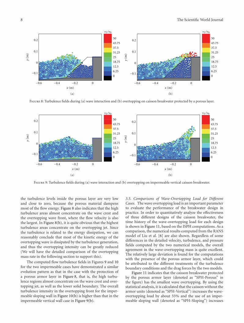
3.4. Discussions of Flow Turbulence Field for Different Cases.The flow turbulence fields in front of the caisson are shown inFigures 8, 9, and 10, respectively, for the three different designcases. In the figures, the turbulence eddy viscosity valueshave been normalized by the laminar viscosity to representthe equivalent turbulence intensity. As shown in Figure 8,
8 The Scientific World Journal
−0.6 −0.4 −0.2 0
−0.1
0
0.1
0.2
y(m
)
x (m)
0
6.25
12.5
18.75
25
31.25
37.5
43.75
50
AT /A0
(a)
−0.6 −0.4 −0.2 0
−0.1
0
0.1
0.2
y(m
)
x (m)
0
6.25
12.5
18.75
25
31.25
37.5
43.75
50
AT /A0
(b)
Figure 8: Turbulence fields during (a) wave interaction and (b) overtopping on caisson breakwater protected by a porous layer.
−0.6 −0.4 −0.2 0
−0.1
0
0.1
0.2
y(m
)
x (m)
0
6.25
12.5
18.75
25
31.25
37.5
43.75
50
AT /A0
(a)
−0.6 −0.4 −0.2 0
−0.1
0
0.1
0.2y
(m)
x (m)
0
6.25
12.5
18.75
25
31.25
37.5
43.75
50
AT /A0
(b)
Figure 9: Turbulence fields during (a) wave interaction and (b) overtopping on impermeable vertical caisson breakwater.
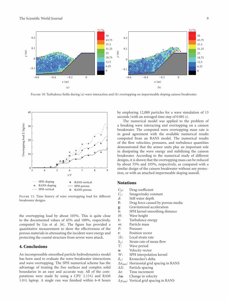
the turbulence levels inside the porous layer are very lowand close to zero, because the porous material dampensmost of the flow energy. Figure 8 also indicates that the highturbulence areas almost concentrate on the wave crest andthe overtopping wave front, where the flow velocity is alsothe largest. In Figure 8(b), it is quite obvious that the highestturbulence areas concentrate on the overtopping jet. Sincethe turbulence is related to the energy dissipation, we canreasonably conclude that most of the kinetic energy of theovertopping wave is dissipated by the turbulence generation,and thus the overtopping intensity can be greatly reduced(We will have the detailed comparison of the overtoppingmass rate in the following section to support this).
The computed flow turbulence fields in Figures 9 and 10for the two impermeable cases have demonstrated a similarevolution pattern as that in the case with the protection ofa porous armor layer in Figure 8, that is, the high turbu-lence regions almost concentrate on the wave crest and over-topping jet, as well as the lower solid boundary. The overallturbulence intensity in the overtopping front for the imper-meable sloping wall in Figure 10(b) is higher than that in theimpermeable vertical wall case in Figure 9(b).
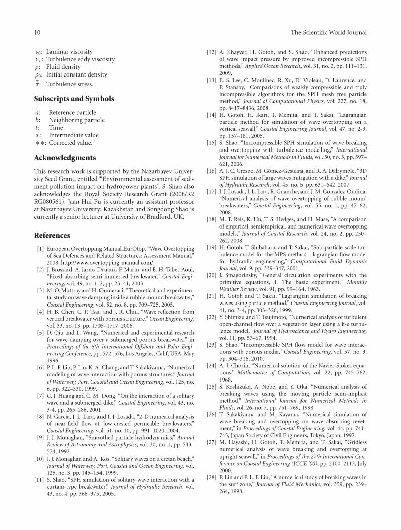
3.5. Comparisons of Wave-Overtopping Load for DifferentCases. The wave overtopping load is an important parameterto evaluate the performance of the breakwater design inpractice. In order to quantitatively analyze the effectivenessof three different designs of the caisson breakwater, thetime history of the wave-overtopping load for each designis shown in Figure 11, based on the ISPH computations. As acomparison, the numerical results computed from the RANSmodel of Liu et al. [6] are also shown. Regardless of somedifferences in the detailed velocity, turbulence, and pressurefields computed by the two numerical models, the overallagreement in the wave-overtopping mass is quite excellent.The relatively large deviation is found for the computationswith the presence of the porous armor layer, which couldbe attributed to the different treatments of the turbulenceboundary conditions and the drag forces by the two models.
Figure 11 indicates that the caisson breakwater protectedby the porous armor layer (denoted as “SPH-Porous” inthe figure) has the smallest wave overtopping. By using thestatistical analysis, it is calculated that the caisson without thearmor units (denoted as “SPH-Vertical”) increases the wave-overtopping load by about 55% and the use of an imper-meable sloping wall (denoted as “SPH-Sloping”) increases
The Scientific World Journal 9
−0.6 −0.4 −0.2 0
−0.1
0
0.1
0.2
y(m
)
x (m)
0
6.25
12.5
18.75
25
31.25
37.5
43.75
50
AT /A0
(a)
−0.6 −0.4 −0.2 0
−0.1
0
0.1
0.2
y(m
)
x (m)
0
6.25
12.5
18.75
25
31.25
37.5
43.75
50
AT /A0
(b)
Figure 10: Turbulence fields during (a) wave interaction and (b) overtopping on impermeable sloping caisson breakwater.
3 4 5 6 7 8 90
10
20
30
40
SPH-slopingRANS-slopingSPH-vertical
RANS-verticalSPH-porousRANS-porous
t/T
Ove
rtop
pin
g lo
adΣ
(kg/
m)
Figure 11: Time history of wave overtopping load for differentbreakwater designs.
the overtopping load by about 105%. This is quite closeto the documented values of 45% and 100%, respectively,computed by Liu et al. [6]. The figure has provided aquantitative measurement to show the effectiveness of theporous materials in attenuating the incident wave energy andprotecting the coastal structure from severe wave attack.
4. Conclusions
An incompressible smoothed particle hydrodynamics modelhas been used to evaluate the wave-breakwater interactionsand wave overtopping. The SPH numerical scheme has theadvantage of treating the free surfaces and complex solidboundaries in an easy and accurate way. All of the com-putations were made by using a CPU 2.13 G and RAM1.0 G laptop. A single run was finished within 6–8 hours
by employing 12,000 particles for a wave simulation of 13seconds (with an averaged time step of 0.001 s).
The numerical model was applied to the problem ofa breaking wave interacting and overtopping on a caissonbreakwater. The computed wave overtopping mass rate isin good agreement with the available numerical resultscomputed from an RANS model. The numerical resultsof the flow velocities, pressures, and turbulence quantitiesdemonstrated that the armor units play an important rolein dissipating the wave energy and stabilizing the caissonbreakwater. According to the numerical study of differentdesigns, it is shown that the overtopping mass can be reducedby about 55% and 105%, respectively, as compared with asimilar design of the caisson breakwater without any protec-tion, or with an attached impermeable sloping seawall.
Notations
CD: Drag coefficientCs: Smagorinsky constantd: Still water depthF: Drag force caused by porous mediag: Gravitational accelerationh: SPH kernel smoothing distanceH : Wave heightk: Turbulence energym: Particle massP: Pressurer: Position vector|S|: Local strain rateSi j : Strain rate of mean flowT : Wave periodu: Velocity vectorW : SPH interpolation kernelδi j : Kronecker’s deltaΔxmin: Horizontal grid spacing in RANSΔX : Particle spacingΔt: Time incrementΔu: Change in velocityΔymin: Vertical grid spacing in RANS
10 The Scientific World Journal
ν0: Laminar viscosityνT : Turbulence eddy viscosityρ: Fluid densityρ0: Initial constant density⇒τ : Turbulence stress.
Subscripts and Symbols
a: Reference particleb: Neighboring particlet: Time∗: Intermediate value∗∗: Corrected value.
Acknowledgments
This research work is supported by the Nazarbayev Univer-sity Seed Grant, entitled “Environmental assessment of sedi-ment pollution impact on hydropower plants”. S. Shao alsoacknowledges the Royal Society Research Grant (2008/R2RG080561). Jaan Hui Pu is currently an assistant professorat Nazarbayev University, Kazakhstan and Songdong Shao iscurrently a senior lecturer at University of Bradford, UK.
References
[1] European Overtopping Manual EurOtop, “Wave Overtoppingof Sea Defences and Related Structures: Assessment Manual,”2008, http://www.overtopping-manual.com/.
[2] J. Brossard, A. Jarno-Druaux, F. Marin, and E. H. Tabet-Aoul,“Fixed absorbing semi-immersed breakwater,” Coastal Engi-neering, vol. 49, no. 1-2, pp. 25–41, 2003.
[3] M. O. Muttray and H. Oumeraci, “Theoretical and experimen-tal study on wave damping inside a rubble mound breakwater,”Coastal Engineering, vol. 52, no. 8, pp. 709–725, 2005.
[4] H. B. Chen, C. P. Tsai, and J. R. Chiu, “Wave reflection fromvertical breakwater with porous structure,” Ocean Engineering,vol. 33, no. 13, pp. 1705–1717, 2006.
[5] D. Qiu and L. Wang, “Numerical and experimental researchfor wave damping over a submerged porous breakwater,” inProceedings of the 6th International Offshore and Polar Engi-neering Conference, pp. 572–576, Los Angeles, Calif, USA, May1996.
[6] P. L. F. Liu, P. Lin, K. A. Chang, and T. Sakakiyama, “Numericalmodeling of wave interaction with porous structures,” Journalof Waterway, Port, Coastal and Ocean Engineering, vol. 125, no.6, pp. 322–330, 1999.
[7] C. J. Huang and C. M. Dong, “On the interaction of a solitarywave and a submerged dike,” Coastal Engineering, vol. 43, no.3-4, pp. 265–286, 2001.
[8] N. Garcia, J. L. Lara, and I. J. Losada, “2-D numerical analysisof near-field flow at low-crested permeable breakwaters,”Coastal Engineering, vol. 51, no. 10, pp. 991–1020, 2004.
[9] J. J. Monaghan, “Smoothed particle hydrodynamics,” AnnualReview of Astronomy and Astrophysics, vol. 30, no. 1, pp. 543–574, 1992.
[10] J. J. Monaghan and A. Kos, “Solitary waves on a cretan beach,”Journal of Waterway, Port, Coastal and Ocean Engineering, vol.125, no. 3, pp. 145–154, 1999.
[11] S. Shao, “SPH simulation of solitary wave interaction with acurtain-type breakwater,” Journal of Hydraulic Research, vol.43, no. 4, pp. 366–375, 2005.
[12] A. Khayyer, H. Gotoh, and S. Shao, “Enhanced predictionsof wave impact pressure by improved incompressible SPHmethods,” Applied Ocean Research, vol. 31, no. 2, pp. 111–131,2009.
[13] E. S. Lee, C. Moulinec, R. Xu, D. Violeau, D. Laurence, andP. Stansby, “Comparisons of weakly compressible and trulyincompressible algorithms for the SPH mesh free particlemethod,” Journal of Computational Physics, vol. 227, no. 18,pp. 8417–8436, 2008.
[14] H. Gotoh, H. Ikari, T. Memita, and T. Sakai, “Lagrangianparticle method for simulation of wave overtopping on avertical seawall,” Coastal Engineering Journal, vol. 47, no. 2-3,pp. 157–181, 2005.
[15] S. Shao, “Incrompressible SPH simulation of wave breakingand overtopping with turbulence modelling,” InternationalJournal for Numerical Methods in Fluids, vol. 50, no. 5, pp. 597–621, 2006.
[16] A. J. C. Crespo, M. Gomez-Gesteira, and R. A. Dalrymple, “3DSPH simulation of large waves mitigation with a dike,” Journalof Hydraulic Research, vol. 45, no. 5, pp. 631–642, 2007.
[17] I. J. Losada, J. L. Lara, R. Guanche, and J. M. Gonzalez-Ondina,“Numerical analysis of wave overtopping of rubble moundbreakwaters,” Coastal Engineering, vol. 55, no. 1, pp. 47–62,2008.
[18] M. T. Reis, K. Hu, T. S. Hedges, and H. Mase, “A comparisonof empirical, semiempirical, and numerical wave overtoppingmodels,” Journal of Coastal Research, vol. 24, no. 2, pp. 250–262, 2008.
[19] H. Gotoh, T. Shibahara, and T. Sakai, “Sub-particle-scale tur-bulence model for the MPS method—lagrangian flow modelfor hydraulic engineering,” Computational Fluid DynamicJournal, vol. 9, pp. 339–347, 2001.
[20] J. Smagorinsky, “General circulation experiments with theprimitive equations, I. The basic experiment,” MonthlyWeather Review, vol. 91, pp. 99–164, 1963.
[21] H. Gotoh and T. Sakai, “Lagrangian simulation of breakingwaves using particle method,” Coastal Engineering Journal, vol.41, no. 3-4, pp. 303–326, 1999.
[22] Y. Shimizu and T. Tsujimoto, “Numerical analysis of turbulentopen-channel flow over a vegetation layer using a k-ε turbu-lence model,” Journal of Hydroscience and Hydro Engineering,vol. 11, pp. 57–67, 1994.
[23] S. Shao, “Incompressible SPH flow model for wave interac-tions with porous media,” Coastal Engineering, vol. 57, no. 3,pp. 304–316, 2010.
[24] A. J. Chorin, “Numerical solution of the Navier-Stokes equa-tions,” Mathematics of Computation, vol. 22, pp. 745–762,1968.
[25] S. Koshizuka, A. Nobe, and Y. Oka, “Numerical analysis ofbreaking waves using the moving particle semi-implicitmethod,” International Journal for Numerical Methods inFluids, vol. 26, no. 7, pp. 751–769, 1998.
[26] T. Sakakiyama and M. Kayama, “Numerical simulation ofwave breaking and overtopping on wave absorbing revet-ment,” in Proceedings of Coastal Engineering, vol. 44, pp. 741–745, Japan Society of Civil Engineers, Tokyo, Japan, 1997.
[27] M. Hayashi, H. Gotoh, T. Memita, and T. Sakai, “Gridlessnumerical analysis of wave breaking and overtopping atupright seawall,” in Proceedings of the 27th International Con-ference on Coastal Engineering (ICCE ’00), pp. 2100–2113, July2000.
[28] P. Lin and P. L. F. Liu, “A numerical study of breaking waves inthe surf zone,” Journal of Fluid Mechanics, vol. 359, pp. 239–264, 1998.

International Journal of
AerospaceEngineeringHindawi Publishing Corporationhttp://www.hindawi.com Volume 2010
RoboticsJournal of
Hindawi Publishing Corporationhttp://www.hindawi.com Volume 2014
Hindawi Publishing Corporationhttp://www.hindawi.com Volume 2014
Active and Passive Electronic Components
Control Scienceand Engineering
Journal of
Hindawi Publishing Corporationhttp://www.hindawi.com Volume 2014
International Journal of
RotatingMachinery
Hindawi Publishing Corporationhttp://www.hindawi.com Volume 2014
Hindawi Publishing Corporation http://www.hindawi.com
Journal ofEngineeringVolume 2014
Submit your manuscripts athttp://www.hindawi.com
VLSI Design
Hindawi Publishing Corporationhttp://www.hindawi.com Volume 2014
Hindawi Publishing Corporationhttp://www.hindawi.com Volume 2014
Shock and Vibration
Hindawi Publishing Corporationhttp://www.hindawi.com Volume 2014
Civil EngineeringAdvances in
Acoustics and VibrationAdvances in
Hindawi Publishing Corporationhttp://www.hindawi.com Volume 2014
Hindawi Publishing Corporationhttp://www.hindawi.com Volume 2014
Electrical and Computer Engineering
Journal of
Advances inOptoElectronics
Hindawi Publishing Corporation http://www.hindawi.com
Volume 2014
The Scientific World JournalHindawi Publishing Corporation http://www.hindawi.com Volume 2014
SensorsJournal of
Hindawi Publishing Corporationhttp://www.hindawi.com Volume 2014
Modelling & Simulation in EngineeringHindawi Publishing Corporation http://www.hindawi.com Volume 2014
Hindawi Publishing Corporationhttp://www.hindawi.com Volume 2014
Chemical EngineeringInternational Journal of Antennas and
Propagation
International Journal of
Hindawi Publishing Corporationhttp://www.hindawi.com Volume 2014
Hindawi Publishing Corporationhttp://www.hindawi.com Volume 2014
Navigation and Observation
International Journal of
Hindawi Publishing Corporationhttp://www.hindawi.com Volume 2014
DistributedSensor Networks
International Journal of


![Mesotherapy:FromHistoricalNotestoScientificEvidenceand ...downloads.hindawi.com/journals/tswj/2020/3542848.pdf · mesotherapy[23–25].Itshouldbenotedthatthephysio- logical solution](https://img.pdfslide.us/doc/110x75/5f0f49317e708231d44367e2/mesotherapyfromhistoricalnotestoscientificevidenceand-mesotherapy23a25itshouldbenotedthatthephysio-.jpg)


![OralHealthofChildrenwithAutism:TheInfluenceofParental ...downloads.hindawi.com/journals/tswj/2020/8329426.pdf[10].Ontheotherhand,inseveralstudies,poororalhygiene andtheresultingperiodontaldiseasewerereportedtobe](https://img.pdfslide.us/doc/110x75/603ae7230531e74c7e52a52f/oralhealthofchildrenwithautismtheinfluenceofparental-10ontheotherhandinseveralstudiespoororalhygiene.jpg)


![TechnologiesforBeneficialMicroorganismsInocula ...downloads.hindawi.com/journals/tswj/2012/491206.pdf · TechnologiesforBeneficialMicroorganismsInocula ... 13–16]. The policies](https://img.pdfslide.us/doc/110x75/5ae3cbcd7f8b9ae74a8e3a7f/technologiesforbenecialmicroorganismsinocula-cialmicroorganismsinocula.jpg)