Embed Size (px)
Citation preview

Smooth Material Flow by strengthening Production
Engineering

Profile of Mikito SHIRAI• 1984 Graduate from Univ. of Tokyo, Naval Architect• 1986 MTech, Univ. of Tokyo• 1986-2002: IHI Ship & Offshore
– Hull form design, Develop CFD for non linear bow wave simulation– In charge Production Design Hull and Production Engineering– Improve bending information, nesting process, accuracy control and block-outfitting
process • 2003 -2005: SAMSUNG, Korea
– Responsible for improving the accuracy of hull steel work especially curved blocks• 2006: Tsuneishi CEBU Philippine, GM Quality Assurance• 2007-2009: Pipavav , India as Head of Production Engineering and Planning
– Organized 25 fresh engineers to manage all production information for hull steel work• 2009-: Head of Production, GBD Bharatishipyard
– Installed Line heating method with help of YANO for bending and fairing– Organized 120 Indian workers directly and constructed Hull part of OSV
As for Production man of shipbuilding, I have been involved more than 180 projects partially or fully from aluminum boats to OSV, VLCC and FPSO.
Today’s presentation
1. What is the best productivity? & Where we are?
2. What are the differences?3. PE is the start of the productivity and smooth
material flow is the first activity of PE.4. How to get good smooth material flow
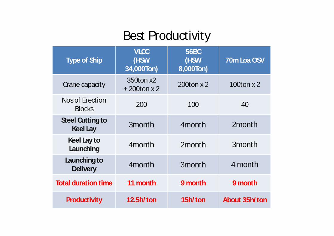
Best Productivity
Type of ShipVLCC(HSW
34,000Ton)
56BC(HSW
8,000Ton)70m Loa OSV
Crane capacity 350ton x2 + 200ton x 2 200ton x 2 100ton x 2
Nos of Erection Blocks 200 100 40
Steel Cutting to Keel Lay 3month 4month 2month
Keel Lay to Launching 4month 2month 3month
Launching to Delivery 4month 3month 4 month
Total duration time 11 month 9 month 9 month
Productivity 12.5h/ton 15h/ton About 35h/ton
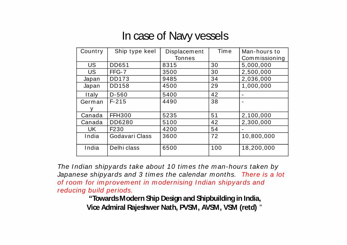
In case of Navy vesselsCountry Ship type keel Displacement
TonnesTime Man-hours to
CommissioningUS DD651 8315 30 5,000,000US FFG-7 3500 30 2,500,000
Japan DD173 9485 34 2,036,000Japan DD158 4500 29 1,000,000Italy D-560 5400 42 -
Germany
F-215 4490 38 -
Canada FFH300 5235 51 2,100,000Canada DD6280 5100 42 2,300,000
UK F230 4200 54 -India Godavari Class 3600 72 10,800,000
India Delhi class 6500 100 18,200,000
The Indian shipyards take about 10 times the man-hours taken by Japanese shipyards and 3 times the calendar months. There is a lot of room for improvement in modernising Indian shipyards and reducing build periods.
“Towards Modern Ship Design and Shipbuilding in India, Vice Admiral Rajeshwer Nath, PVSM, AVSM, VSM (retd) ”
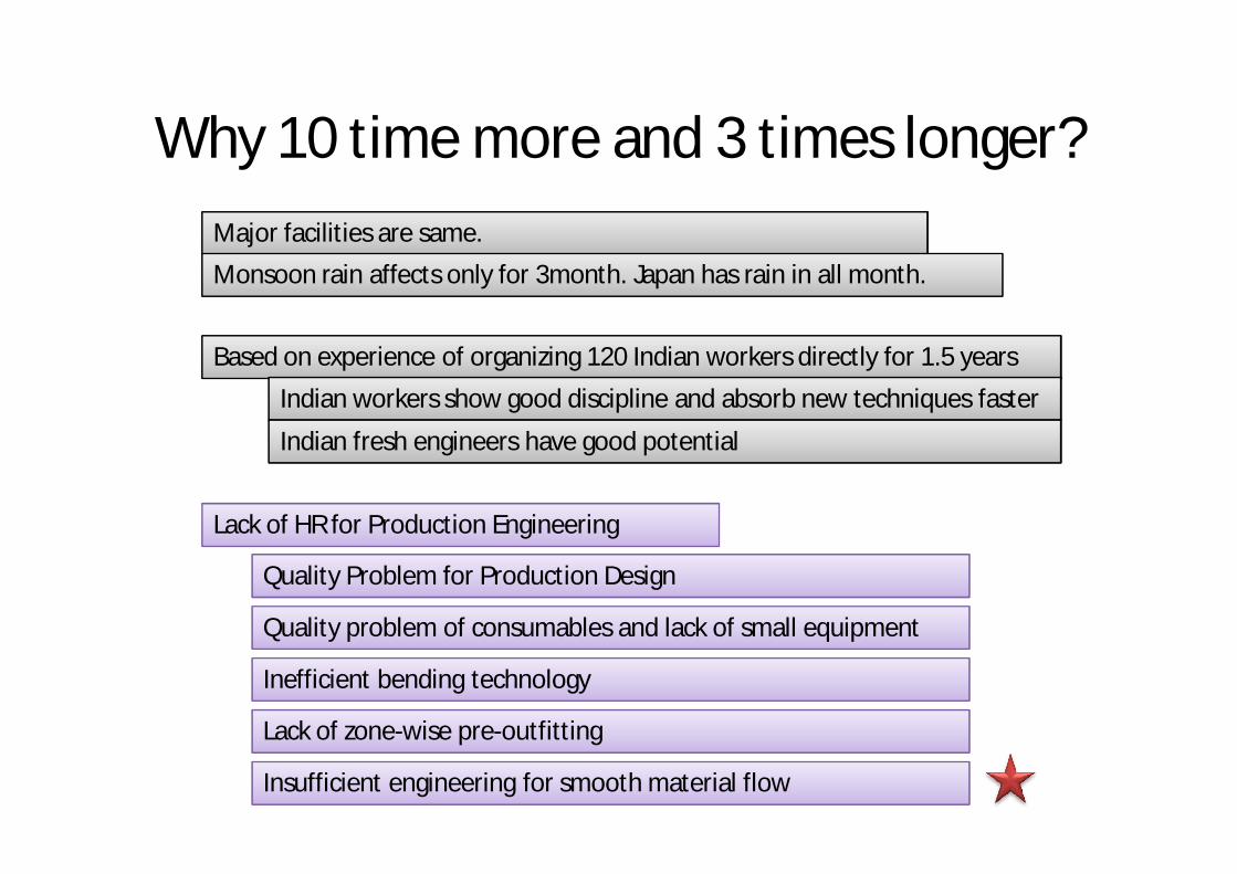
Why 10 time more and 3 times longer?
Based on experience of organizing 120 Indian workers directly for 1.5 years
Indian workers show good discipline and absorb new techniques faster
Indian fresh engineers have good potential
Lack of HR for Production Engineering
Quality Problem for Production Design
Quality problem of consumables and lack of small equipment
Major facilities are same.Monsoon rain affects only for 3month. Japan has rain in all month.
Inefficient bending technology
Lack of zone-wise pre-outfitting
Insufficient engineering for smooth material flow
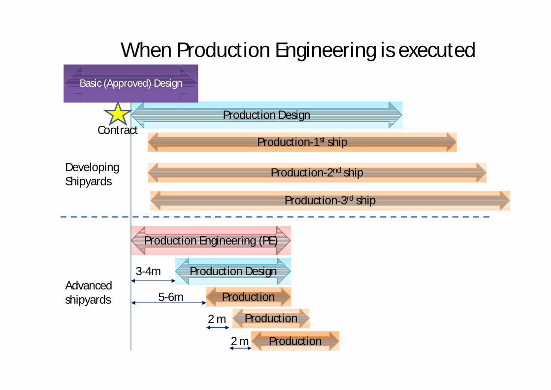
When Production Engineering is executed
Production DesignProduction Design
Production-1st shipProduction-1st ship
Production-2nd shipProduction-2nd ship
Production-3rd shipProduction-3rd ship
Production Engineering (PE)Production Engineering (PE)
Production DesignProduction Design
ProductionProduction
ProductionProduction
ProductionProduction
Contract
Advanced shipyards
3-4m
5-6m
2 m
2 m
Developing Shipyards
Basic (Approved) Design
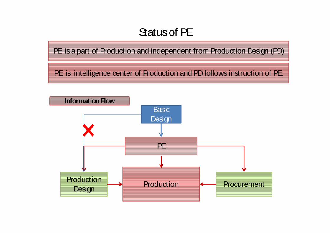
Status of PE
PE is a part of Production and independent from Production Design (PD)
PE is intelligence center of Production and PD follows instruction of PE.
Basic Design
PE
Production Design ProcurementProduction
Information Flow
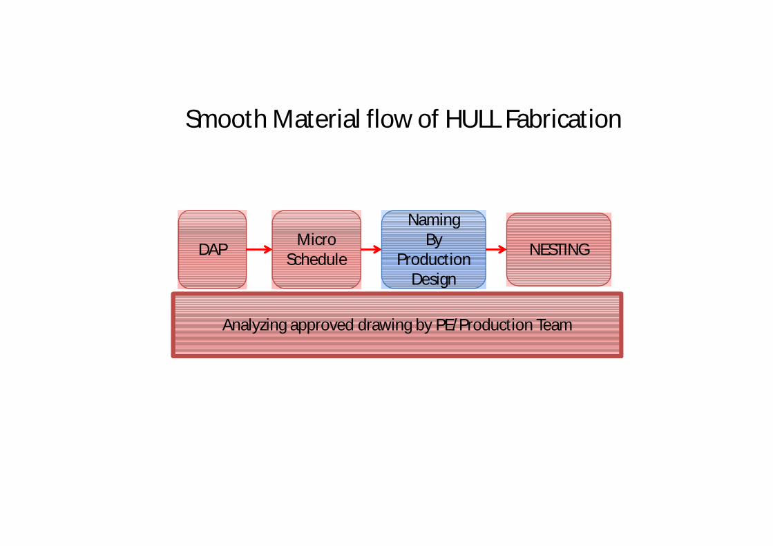
Smooth Material flow of HULL Fabrication
DAP Micro Schedule
Naming
Design
NamingBy
Production Design
NESTING
Analyzing approved drawing by PE/Production Team
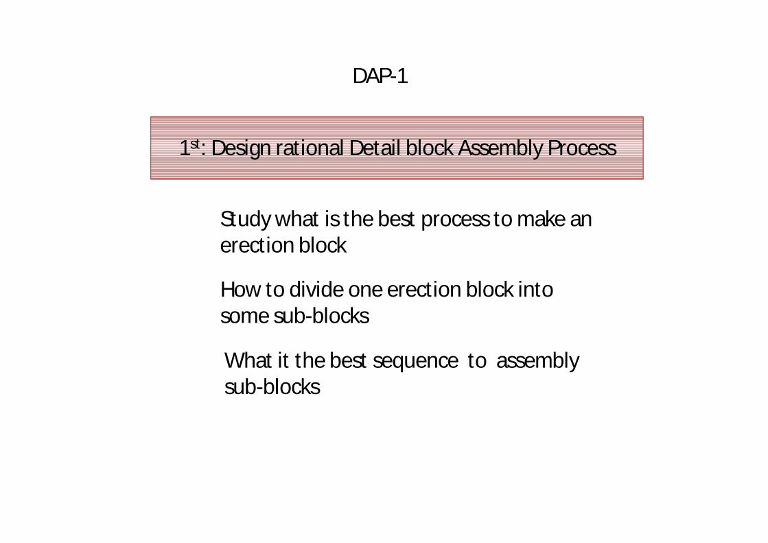
DAP-1
1st: Design rational Detail block Assembly Process
Study what is the best process to make an erection block
How to divide one erection block into some sub-blocks
What it the best sequence to assembly sub-blocks
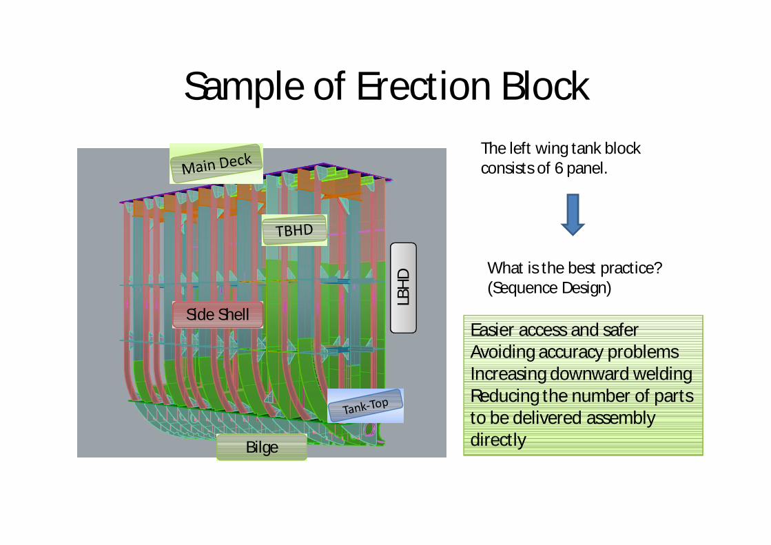
Sample of Erection Block
Bilge
LBHD
Side Shell
The left wing tank block consists of 6 panel.
What is the best practice?(Sequence Design)
Easier access and saferAvoiding accuracy problemsIncreasing downward weldingReducing the number of parts to be delivered assembly directly
TBHD
Floors
LBHD
TT
FloorsTT
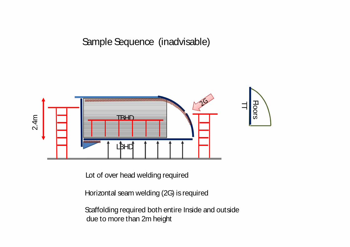
Sample Sequence (inadvisable)
Lot of over head welding required
Scaffolding required both entire Inside and outsidedue to more than 2m height
Horizontal seam welding (2G) is required
2.4m
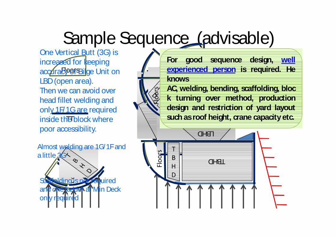
Sample Sequence (advisable)
TBHD
Floors
LBHDTT
TBHD
LBHDTBHD LB
HD
TBHD
LBHD
TBHD
LBHD
One Vertical Butt (3G) is increased for keeping accuracy of Bilge Unit on LBD (open area).Then we can avoid over head fillet welding and only 1F/1G are required inside the block where poor accessibility.
Almost welding are 1G/1F and a little 3G
Scaffolding is not required and one ladder at Min Deck only required
For good sequence design, wellexperienced person is required. HeknowsAC, welding, bending, scaffolding, block turning over method, productiondesign and restriction of yard layoutsuch as roof height, crane capacity etc.
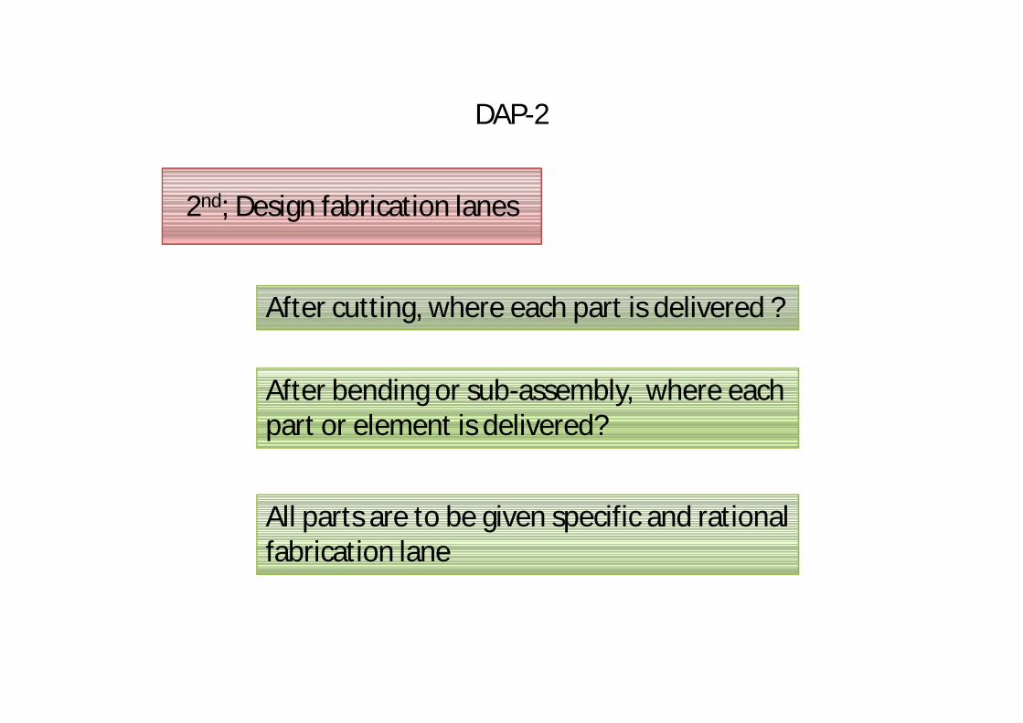
DAP-2
2nd; Design fabrication lanes
After cutting, where each part is delivered ?
After bending or sub-assembly, where each part or element is delivered?
All parts are to be given specific and rational fabrication lane
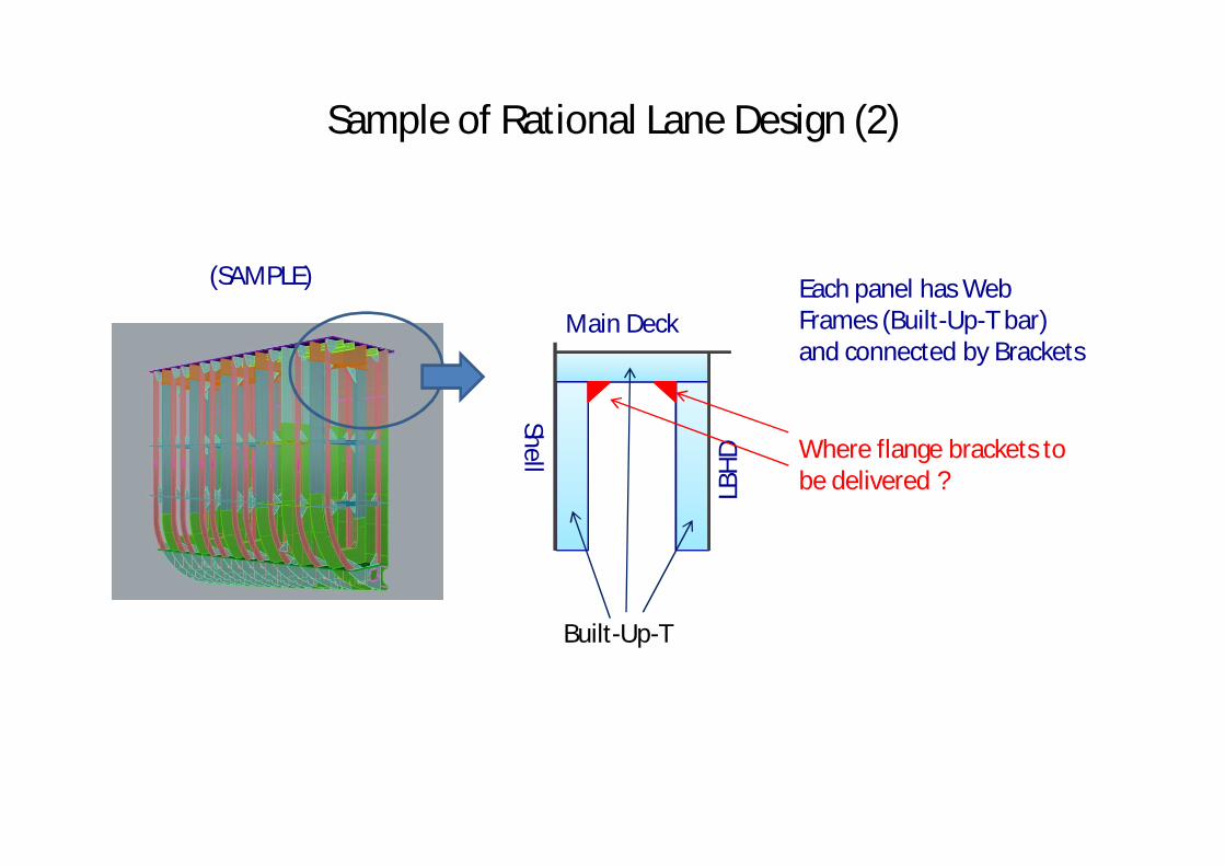
Sample of Rational Lane Design (2)
Shell
Main Deck
LBHD
Each panel has Web Frames (Built-Up-T bar) and connected by Brackets
(SAMPLE)
Built-Up-T
Where flange brackets to be delivered ?
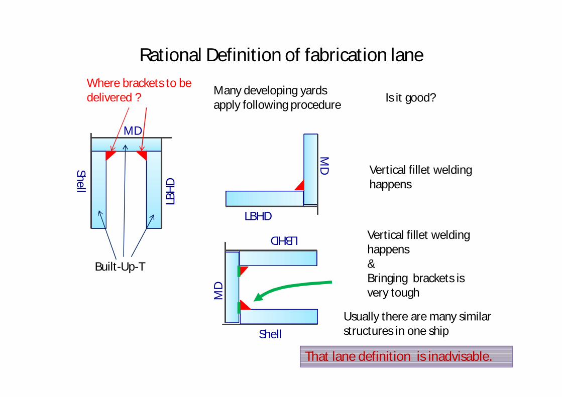
Rational Definition of fabrication lane
Shell
MD
LBHD
Built-Up-T
Where brackets to be delivered ?
LBHD
MD
Shell
LBHD
MD
Many developing yards apply following procedure
Vertical fillet welding happens
Vertical fillet welding happens&Bringing brackets is very tough
Is it good?
That lane definition is inadvisable.
Usually there are many similar structures in one ship
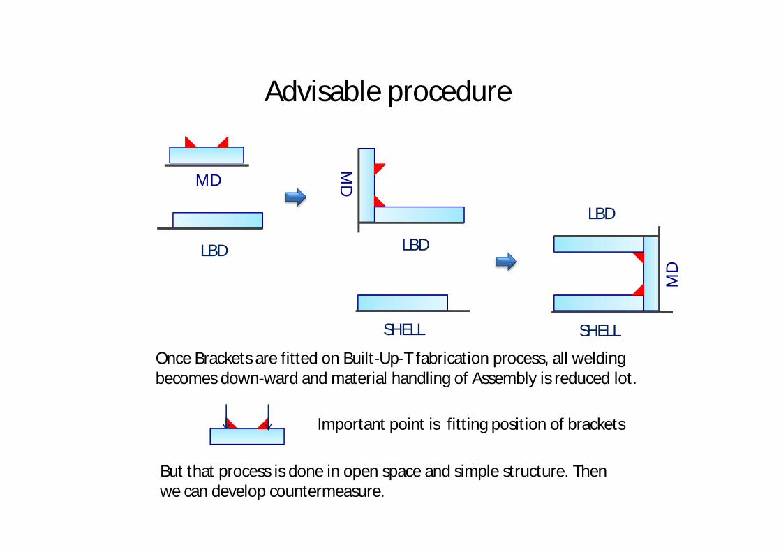
Advisable procedure
MD
LBD
MD
LBD
SHELL SHELL
MD
LBD
Once Brackets are fitted on Built-Up-T fabrication process, all welding becomes down-ward and material handling of Assembly is reduced lot.
But that process is done in open space and simple structure. Then we can develop countermeasure.
Important point is fitting position of brackets
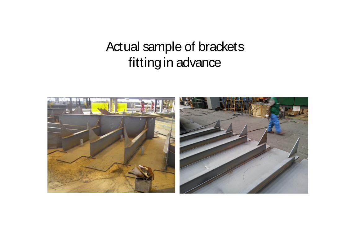
Actual sample of brackets fitting in advance
DAP-3
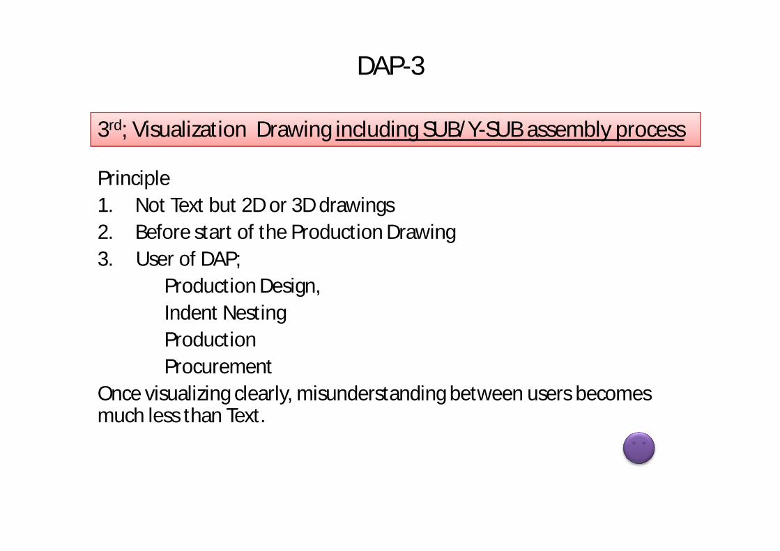
Principle1. Not Text but 2D or 3D drawings2. Before start of the Production Drawing3. User of DAP;
Production Design, Indent NestingProductionProcurement
Once visualizing clearly, misunderstanding between users becomes much less than Text.
3rd; Visualization Drawing including SUB/Y-SUB assembly process
Micro Scheduling-1
Calculate quantities
Calculating welding length and number of work by each step and each stage wise
In case of cutting stage, indent nesting is required to estimate work load.
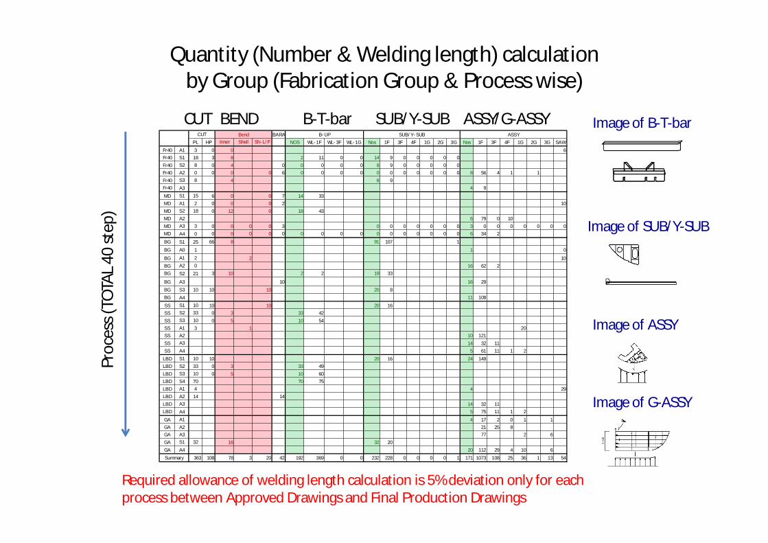
Quantity (Number & Welding length) calculation by Group (Fabrication Group & Process wise)
BARA
PL HP Inner Shell Sh-L/F NOS WL-1F WL-3F WL-1G Nos 1F 3F 4F 1G 2G 3G Nos 1F 3F 4F 1G 2G 3G SAW
Fr40 A1 3 0 0 6
Fr40 S1 18 3 8 2 11 0 0 14 9 0 0 0 0 0
Fr40 S2 8 0 4 0 0 0 0 0 8 9 0 0 0 0 0
Fr40 A2 0 0 0 0 6 0 0 0 0 0 0 0 0 0 0 0 8 56 4 1 1
Fr40 S3 8 4 8 9
Fr40 A3 4 9
MD S1 15 6 0 0 7 14 33
MD A1 2 0 0 0 2 10
MD S2 18 0 12 0 18 43
MD A2 6 79 0 10
MD A3 3 0 0 0 0 3 0 0 0 0 0 0 0 3 0 0 0 0 0 0 0
MD A4 0 0 0 0 0 0 0 0 0 0 0 0 0 0 0 0 0 6 34 2
BG S1 25 66 8 91 107 1
BG A0 1 1 0
BG A1 2 2 10
BG A2 0 16 62 2
BG S2 21 3 10 2 2 19 33
BG A3 10 16 29
BG S3 10 10 10 20 8
BG A4 11 108
SS S1 10 10 10 20 16
SS S2 33 0 3 33 42
SS S3 10 0 5 10 54
SS A1 3 1 20
SS A2 10 121
SS A3 14 32 11
SS A4 5 61 11 1 2
LBD S1 10 10 20 16 24 149
LBD S2 33 0 3 33 49
LBD S3 10 0 5 10 60
LBD S4 70 70 75
LBD A1 4 4 29
LBD A2 14 14
LBD A3 14 32 11
LBD A4 5 75 11 1 2
GA A1 4 17 2 0 1 1
GA A2 21 25 8
GA A3 77 2 6
GA S1 32 16 32 20
GA A4 20 112 29 4 10 6
363 108 78 3 20 42 192 369 0 0 232 228 0 0 0 0 1 171 1073 108 25 36 1 13 54Summary
ASSYCUT Bend B-UP SUB/Y-SUB
Proc
ess (
TOTA
L 40
step
)CUT BEND B-T-bar SUB/Y-SUB ASSY/G-ASSY Image of B-T-bar
Image of SUB/Y-SUB
Image of ASSY
Image of G-ASSY
Required allowance of welding length calculation is 5% deviation only for each process between Approved Drawings and Final Production Drawings
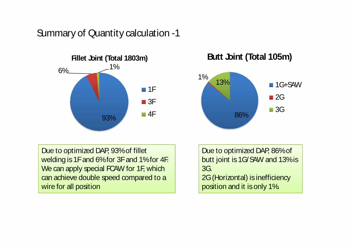
Summary of Quantity calculation -1
Due to optimized DAP, 93% of fillet welding is 1F and 6% for 3F and 1% for 4F.We can apply special FCAW for 1F, which can achieve double speed compared to a wire for all position
Due to optimized DAP, 86% of butt joint is 1G/SAW and 13% is 3G.2G (Horizontal) is inefficiency position and it is only 1%.
93%
6% 1%Fillet Joint (Total 1803m)
1F
3F
4F 86%
1%13%
Butt Joint (Total 105m)
1G+SAW
2G
3G
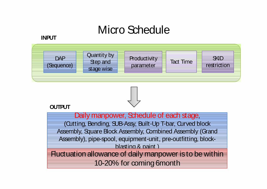
Micro Schedule
Quantity by Step and
stage wise
DAP (Sequence)
Productivity parameter
SKID restrictionTact Time
Daily manpower, Schedule of each stage,
blasting & paint )
Daily manpower, Schedule of each stage,(Cutting, Bending, SUB-Assy, Built-Up T-bar, Curved block
Assembly, Square Block Assembly, Combined Assembly (Grand Assembly), pipe-spool, equipment-unit, pre-outfitting, block-
blasting & paint )Fluctuation allowance of daily manpower is to be within
10-20% for coming 6month
INPUT
OUTPUT
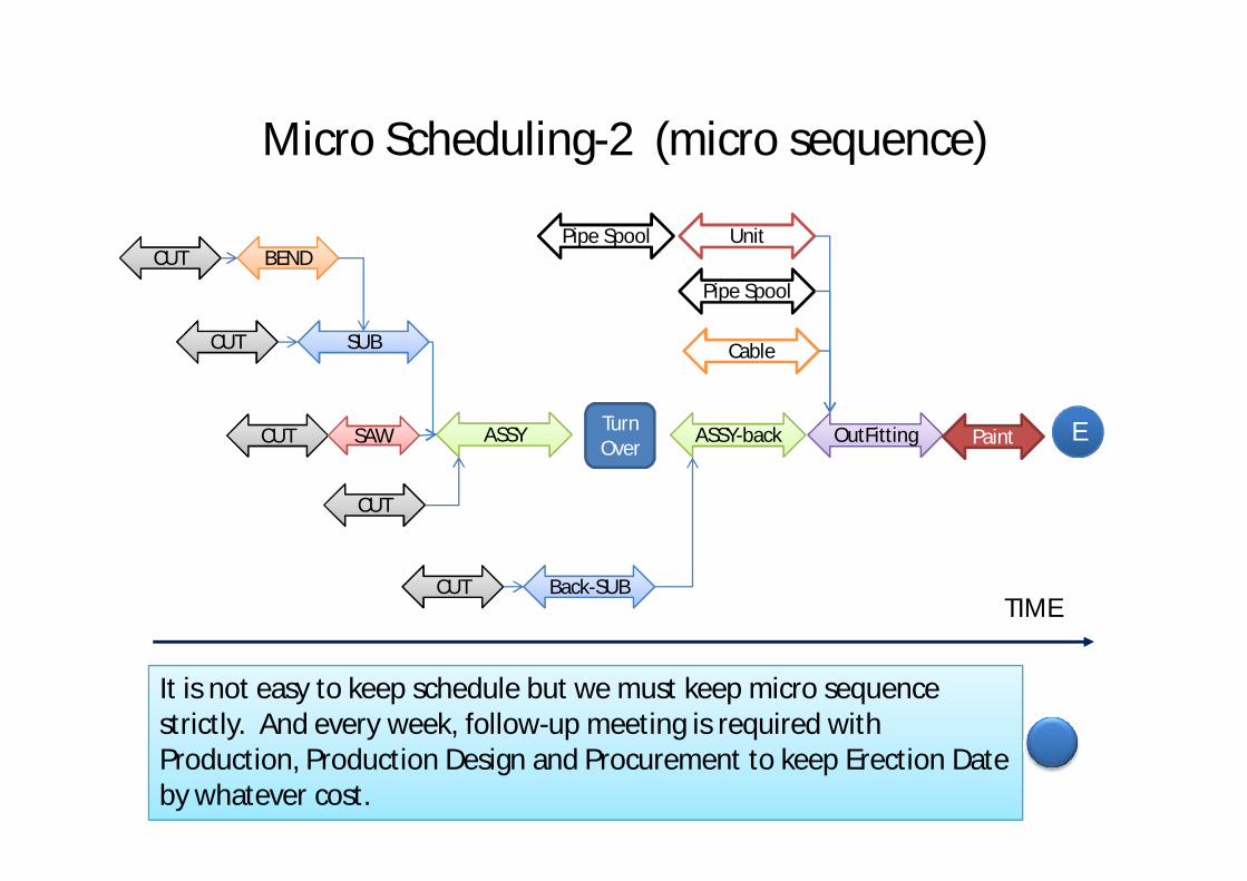
Micro Scheduling-2 (micro sequence)
CUTCUT BENDBEND
SUBSUBCUTCUT
CUTCUT SAWSAW ASSYASSY
CUTCUT
Turn Over
Back-SUBBack-SUBCUTCUT
ASSY-backASSY-back
It is not easy to keep schedule but we must keep micro sequence strictly. And every week, follow-up meeting is required with Production, Production Design and Procurement to keep Erection Date by whatever cost.
TIME
OutFittingOutFitting
Pipe Spool Unit
Cable
Pipe Spool
Paint E
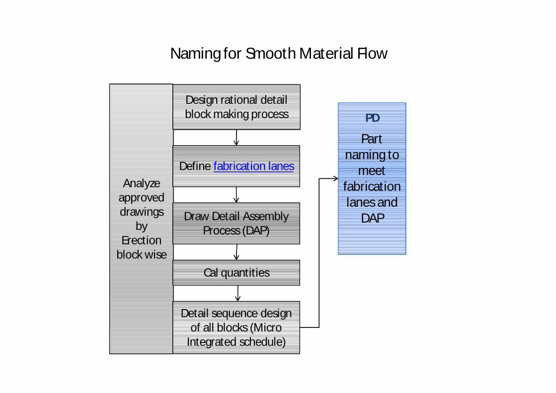
Naming for Smooth Material Flow
Analyze approved drawings
by Erection
block wise
Define fabrication lanes
Design rational detail block making process
Part naming to
meet fabrication lanes and
DAP
Detail sequence design of all blocks (Micro
Integrated schedule)
PD
Draw Detail Assembly Process (DAP)
Cal quantities
Proper Part Naming
Today, several kinds of naming system are proposed.
A proper naming system indicates “Fabrication lanes” of each part.
A cutting shop should be given proper naming which they can segregate parts and deliver them to defined fabrication lane without checking production drawing.
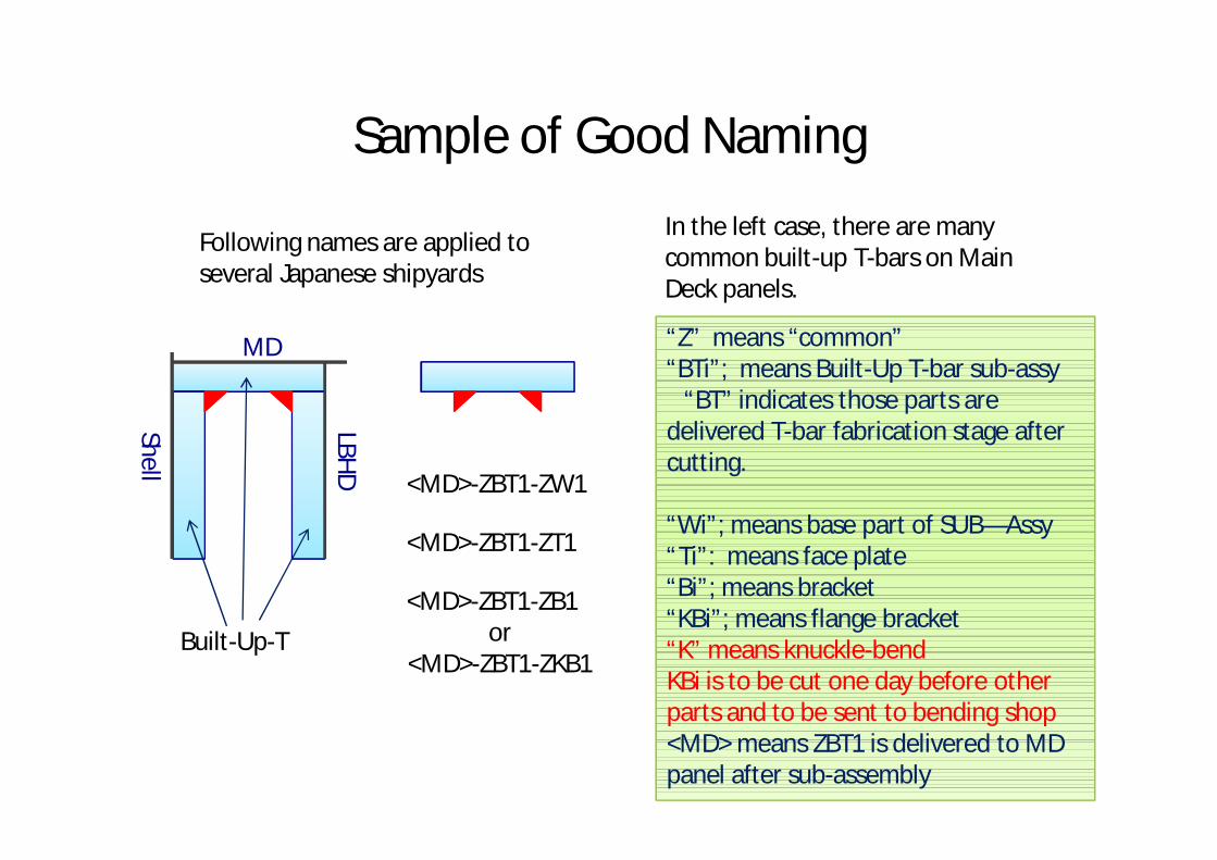
Sample of Good Naming
Shell
MD
Built-Up-T
LBHD
<MD>-ZBT1-ZW1
<MD>-ZBT1-ZT1
<MD>-ZBT1-ZB1or
<MD>-ZBT1-ZKB1
In the left case, there are many common built-up T-bars on Main Deck panels.
“Z” means “common”“BTi”; means Built-Up T-bar sub-assy
“BT” indicates those parts are delivered T-bar fabrication stage after cutting.
“Wi”; means base part of SUB—Assy“Ti”: means face plate“Bi”; means bracket“KBi”; means flange bracket“K” means knuckle-bendKBi is to be cut one day before other parts and to be sent to bending shop<MD> means ZBT1 is delivered to MD panel after sub-assembly
Following names are applied to several Japanese shipyards
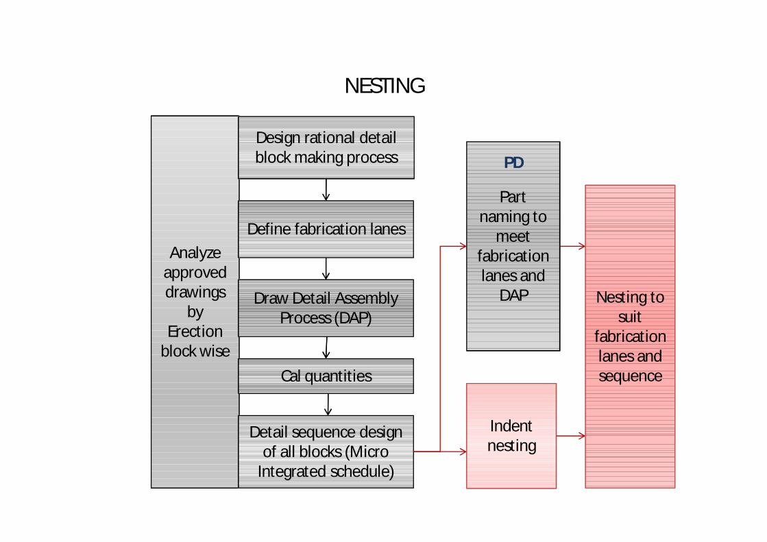
NESTING
Analyze approved drawings
by Erection
block wise
Define fabrication lanes
Design rational detail block making process
Part naming to
meet fabrication lanes and
DAP Nesting to suit
fabrication lanes and sequence
Detail sequence design of all blocks (Micro
Integrated schedule)
PD
Indent nesting
Draw Detail Assembly Process (DAP)
Cal quantities
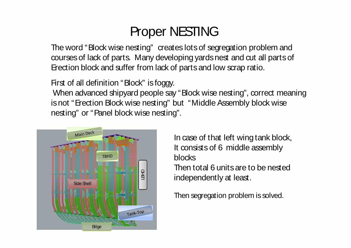
Proper NESTINGThe word “Block wise nesting” creates lots of segregation problem and courses of lack of parts. Many developing yards nest and cut all parts of Erection block and suffer from lack of parts and low scrap ratio.
First of all definition “Block” is foggy. When advanced shipyard people say “Block wise nesting”, correct meaning is not “Erection Block wise nesting” but “Middle Assembly block wise nesting” or “Panel block wise nesting”.
Bilge
LBHD
Side Shell
In case of that left wing tank block,It consists of 6 middle assembly blocksThen total 6 units are to be nested independently at least.
Then segregation problem is solved.
Reducing Intermediate stock
• It is preferable to cut parts just before using.
If we cut parts in advance, we will lose some of them when we need and assembly is hold.
And also segregation problem happen.
For example, SAMSUNG does not allow to keep cut parts more than 3 days.
However, special material such as DH36, EH36 and common parts are exception. They are controlled separately and strictly.
Selection of special control items is also scope of PE.
How to keep good scrap ratio
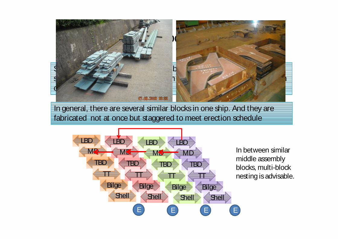
Small Common parts (Z-part) are to be cut in advance using balance space after counting total number on one project and keep them by bin or banded by wire.
In between similar middle assembly blocks, multi-block nesting is advisable.
In general, there are several similar blocks in one ship. And they are fabricated not at once but staggered to meet erection schedule
TTTTBilgeBilge
MDMDTBDTBD
LBDLBD
ShellShell
TTTTBilgeBilge
MDMDTBDTBD
LBDLBD
ShellShell
TTTTBilgeBilge
MDMDTBDTBD
LBDLBD
ShellShell
TTTTBilgeBilge
MDMDTBDTBD
LBDLBD
ShellShell
E E E E
Necessity of Indent Nesting• Usually our shipyards use standard size plates such as 2.5m x 10m.
Then scrap ratio is worse than Japanese or Korean shipyards. Whether using standard size or ready made size is depended on a yard policy.
• Even though using standard plates, Indent Nesting is advisable .
Estimation of cutting work load for CNC needs not “weight” but “the number of plates” per shift.
Considering cost of inventory, it is advisable to procure plates periodically instead of procurement all plates per project.
All multi-block nesting parts should be defined at Indent Nesting.
Conclusion1. PE is essential before start of Production Design for good productivity.
2. PE is the part of Production.
3. Analyzing approved drawing and making DAP and Micro Schedule.
4. Part naming by PD has to indicate fabrication lanes and also common parts.
5. Nesting is to be done by middle assembly block wise and multi block nesting between similar middle blocks is to be applied.
6. Once above all process are done, smooth material flow and good scrap ratio are achieved.
Quick “Copy” and “Execution” is required
Dr.Hisahi Shintoone of the most prominent Japanese industrialist after WWII and leaded Japanese shipbuilding industries to the best productivity in the world.And I am a grand-pupil of Dr. Shinto.
Learning is “Copy” and “Copy” and “Copy” before discussion of ideas.After more than enough, we can start modification of “Copy”.
I wish to start “copy” not from next project but from next block or tomorrow.

Thank you for your attention.