Embed Size (px)
Citation preview
Datasheet
www.rohm.com© 2015 ROHM Co., Ltd. All rights reserved.
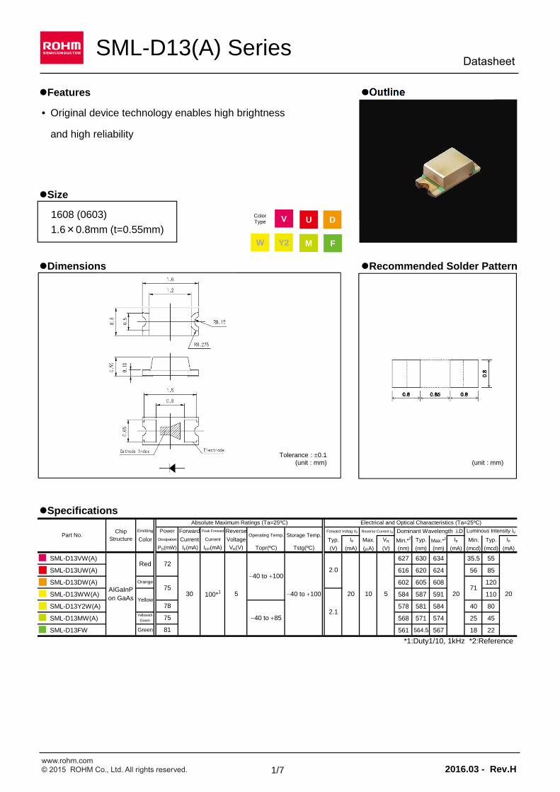
Features Outline
• Original device technology enables high brightness
and high reliability
Size
1006 (0402)
1.0×0.6mm (t=0.2mm)
Dimensions Recommended Solder Pattern
Specifications
Typ. IF Max. VR Min.*2 Typ. Max.*2 IF Min. Typ. IF(V) (mA) (A) (V) (nm) (nm) (nm) (mA) (mcd) (mcd) (mA)
SML-D13VW(A) 627 630 634 35.5 55
SML-D13UW(A) 616 620 624 56 85
SML-D13DW(A) 602 605 608 120
SML-D13WW(A) 584 587 591 110
SML-D13Y2W(A) 578 581 584 40 80
SML-D13MW(A) 568 571 574 25 45
SML-D13FW 561 564.5 567 18 22
*1:Duty1/10, 1kHz *2:Reference
Forward Voltag VF
Voltage
40 to 100
72
7120 10 205100*1
2.0
75 40 to 85
81
205
2.1
Topr(ºC) Tstg(ºC)
40 to 100
Electrical and Optical Characteristics (Ta=25ºC)
Luminous Intensity IVReverse Current IR Dominant Wavelength D
SML-D13(A) Series
Part No.Dissipation Current
PD(mW) IF(mA) IFP(mA)
Current
Peak Forward Reverse
VR(V)
Storage Temp.
AIGaInPon GaAs
Green
30
Yellowish
Green
Emitting Power ForwardChipStructure
Absolute Maximum Ratings (Ta=25ºC)
Orange
ColorOperating Temp.
75
78
Red
Yellow
(unit : mm)Tolerance : 0.1
(unit : mm)
1608 (0603)
1.6×0.8mm (t=0.55mm)
ColorType V
W FM
U D
Y2
1/7 2016.03 - Rev.H

www.rohm.com© 2015 ROHM Co., Ltd. All rights reserved.
Data SheetSML-D13(A) Series
Electrical Characteristics Curves
0.0
0.5
1.0
1.5
0 5 10 15 20 25 30
1
10
100
1.4 1.6 1.8 2.0 2.2 2.40.2
0.4
0.6
0.8
1.0
1.2
1.4
1.6
1.8
-40 -20 0 20 40 60 80 100
0
10
20
30
40
-40 -20 0 20 40 60 80 100
Fig.1 Forward Current - Forward Voltages
FO
RW
AR
D C
UR
RE
NT
: IF
[mA
]
FORWARD VOLTAGE : VF [V]
Fig.2 Luminous Intensity -Atmosphere Temperature
RE
LAT
IVE
LU
MIN
OU
S I
NT
EN
SIT
Y [
a.u.
]
ATMOSPHERE TEMPERATURE : Ta [ºC]
Fig.3 Luminous Intensity - Forward Current
RE
LAT
IVE
LU
MIN
OU
S I
NT
EN
SIT
Y
FORWARD CURRENT : IF [mA]
Fig.4 Derating
MA
XIM
UM
FO
RW
AR
D C
UR
RE
NT
: [
mA
]
AMBIENT TEMPERATURE : Ta [ºC]
Ta=25ºC
Ta=25ºC
IF=20mASML-D13VW(A) SML-D13UW(A)SML-D13DW(A)SML-D13WW(A)SML-D13Y2W(A)SML-D13MW(A)SML-D13FW
reference
SML-D13VW(A) SML-D13UW(A)SML-D13DW(A)SML-D13WW(A)SML-D13Y2W(A)SML-D13MW(A)SML-D13FW
SML-D13VW(A) SML-D13UW(A)SML-D13DW(A)SML-D13WW(A)SML-D13Y2W(A)SML-D13MW(A)SML-D13FW
SML-D13VW(A) SML-D13UW(A)SML-D13DW(A)SML-D13WW(A)SML-D13Y2W(A)SML-D13MW(A)SML-D13FW
2/7 2016.03 - Rev.H
www.rohm.com© 2015 ROHM Co., Ltd. All rights reserved.
Data SheetSML-D13(A) Series
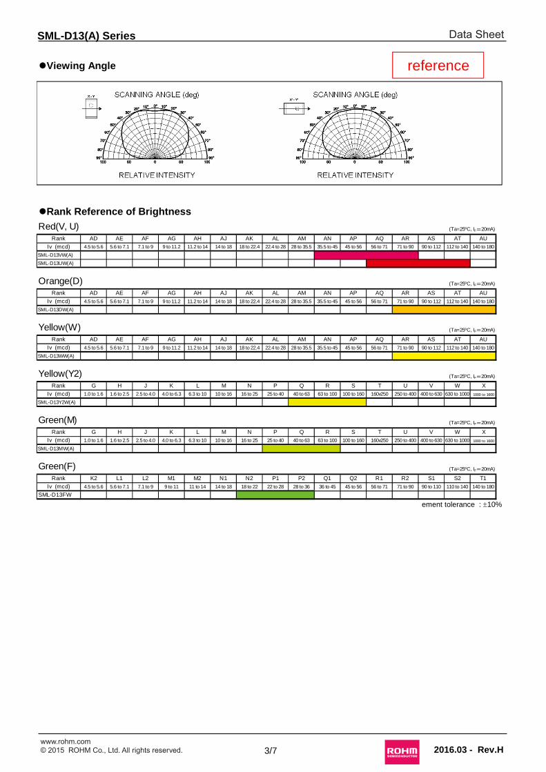
Viewing Angle
Rank Reference of Brightness
ement tolerance : 10%
SCANNING ANGLE (deg)
RELATIVE INTENSITY
SCANNING ANGLE (deg)
RELATIVE INTENSITY
reference
Red(V, U) (Ta=25ºC, IF=20mA)
Rank AD AE AF AG AH AJ AK AL AM AN AP AQ AR AS AT AU
Iv (mcd) 4.5 to 5.6 5.6 to 7.1 7.1 to 9 9 to 11.2 11.2 to 14 14 to 18 18 to 22.4 22.4 to 28 28 to 35.5 35.5 to 45 45 to 56 56 to 71 71 to 90 90 to 112 112 to 140 140 to 180
SML-D13VW(A)
SML-D13UW(A)
Orange(D) (Ta=25ºC, IF=20mA)
Rank AD AE AF AG AH AJ AK AL AM AN AP AQ AR AS AT AU
Iv (mcd) 4.5 to 5.6 5.6 to 7.1 7.1 to 9 9 to 11.2 11.2 to 14 14 to 18 18 to 22.4 22.4 to 28 28 to 35.5 35.5 to 45 45 to 56 56 to 71 71 to 90 90 to 112 112 to 140 140 to 180
SML-D13DW(A)
Yellow(W) (Ta=25ºC, IF=20mA)
Rank AD AE AF AG AH AJ AK AL AM AN AP AQ AR AS AT AU
Iv (mcd) 4.5 to 5.6 5.6 to 7.1 7.1 to 9 9 to 11.2 11.2 to 14 14 to 18 18 to 22.4 22.4 to 28 28 to 35.5 35.5 to 45 45 to 56 56 to 71 71 to 90 90 to 112 112 to 140 140 to 180
SML-D13WW(A)
Yellow(Y2) (Ta=25ºC, IF=20mA)
Rank G H J K L M N P Q R S T U V W X
Iv (mcd) 1.0 to 1.6 1.6 to 2.5 2.5 to 4.0 4.0 to 6.3 6.3 to 10 10 to 16 16 to 25 25 to 40 40 to 63 63 to 100 100 to 160 160v250 250 to 400 400 to 630 630 to 1000 1000 to 1600
SML-D13Y2W(A)
Green(M) (Ta=25ºC, IF=20mA)
Rank G H J K L M N P Q R S T U V W X
Iv (mcd) 1.0 to 1.6 1.6 to 2.5 2.5 to 4.0 4.0 to 6.3 6.3 to 10 10 to 16 16 to 25 25 to 40 40 to 63 63 to 100 100 to 160 160v250 250 to 400 400 to 630 630 to 1000 1000 to 1600
SML-D13MW(A)
Green(F) (Ta=25ºC, IF=20mA)
Rank K2 L1 L2 M1 M2 N1 N2 P1 P2 Q1 Q2 R1 R2 S1 S2 T1
Iv (mcd) 4.5 to 5.6 5.6 to 7.1 7.1 to 9 9 to 11 11 to 14 14 to 18 18 to 22 22 to 28 28 to 36 36 to 45 45 to 56 56 to 71 71 to 90 90 to 110 110 to 140 140 to 180
SML-D13FW
3/7 2016.03 - Rev.H
www.rohm.com© 2015 ROHM Co., Ltd. All rights reserved.
Data SheetSML-D13(A) Series
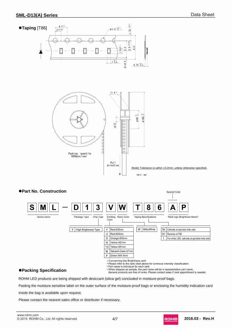
Taping [T86]
Part No. Construction
Packing Specification
ROHM LED products are being shipped with desiccant (silica gel) concluded in moisture-proof bags.
Pasting the moisture sensitive label on the outer surface of the moisture-proof bags or enclosing the humidity indication card
inside the bag is available upon request.
Please contact the nearest sales office or distributer if necessary.
8.0
1.75
3.5
5.5
0~0.51
2
1.9
φ180
φ60
φ13
±0.1
±0.05 φ1.5+0.1 ±
0.1
+1 0 -30
±0.05
0
0.73
4
(Unit:mm)
Packing quantity3000pcs/reel
Pulldirection
(note) Tolerance is within ±0.2mm
unless otherwise specified
11.4 ±1
+0.1-0.07
+0.1-0.07
±0.1
(Note) Tolerance is within 0.2mm, unless otherwise specified.
4/7 2016.03 - Rev.H
www.rohm.com© 2015 ROHM Co., Ltd. All rights reserved.
Data Sheet
2016.03 - Rev.H
SML-D13(A) Series
5/7
lPrecaution (Surface Mount Device)1.Storage
If the product is heated during the reflow under the condition of hygroscopic state, it may vaporize and expand which will influence the performance of the product. Therefore, the package is waterproof. Please use the product following the conditions:
・Using ConditionsClassification Temperature Humidity Expiration Date Remark
①Before using 5 to 30ºC 30 to 70%RH Within 1 year from Receiving Storage with waterproof package
②After opening package 5 to 30ºC Below 70%RH Within 168h Please storing in the airtight container with
our desiccant (silica gel)
・BakingBake the product in case of below:①The expiration date is passed.②The color of indicator (silica gel) turned from blue to colorless or from green to pink. (Even if the product is
within the expiration date.)
・Baking ConditionsTemperature Time Humidity
60±3ºC 12 to 24h Below 20%RH
Remark
・Bake products in reel.・Reel and embossed tape are easy to be deformed when baking, so please try not to apply stress on it.・Recommend bake once.
2.Application Methods2-1. Precaution for Drive System and Off Mode
Design the circuit without the electric load exceeding the ABSOLUTE MAXIMUM RATING that applies on the products. If drive by constant voltage, it may cause current deviation of the LED and result in deviation of luminous intensity, so we recommend to drive by constant current. (Deviation of VF Value will cause deviation of current in LED.) Furthermore, for off mode, please do not apply voltage neither forward nor reverse. Especially, for the products with the Ag-paste used in the die bonding, there’s high possibility to cause electro migration and result in function failure.
2-2. Operation Life SpanThere’s possibility for intensity of light drop according to working conditions and environments (applied
current, surrounding temperature and humidity, corrosive gases), please call our Sales staffs for inquiries about the concerned application below.
①Longtime intensity of light life②On mode all the time
2-3.Applied Stress on ProductThe top of the LED is very soft, which the silicon resin is used as sealing resin. Therefore, please pay attention
to the overstress on it which may influence its reliability.
2-4.UsageThe Product is LED. We are not responsible for the usage as the diode such as Protection Chip, Rectifier,
Switching and so on.
3. Others3-1. Surrounding Gas
Notice that if it is stored under the condition of acid gas (chlorine gas, sulfured gas) or alkali gas (ammonia), it may result in low soldering ability (caused by the change in quality of the plating surface ) or optical characteristics changes (light intensity, chrominance) and change in quality of die bonding (Ag-paste) materials. All of the above will cause function failure of the products.
Therefore, please pay attention to the storage environment for mounted product (concern the generated gas of the surrounding parts of the products and the atmospheric environment).
www.rohm.com© 2015 ROHM Co., Ltd. All rights reserved.
Data Sheet
2016.03 - Rev.H
SML-D13(A) Series
6/7
3-2. Electrostatic DamageThe product is part of semiconductor and electrostatic sensitive, there’s high possibility to be damaged by the
electrostatic discharge. Please take appropriate measures to avoid the static electricity from human body and earthing of production equipment. The resistance values of electrostatic discharge (actual values) vary with products, therefore, please call our Sales staffs for inquiries.
3-3. Electromagnetic WavePlease concern the influence on LED in case of application with strong electromagnetic wave such as IH
(Induction heating).
4.Mounting4-1. Soldering・No resin hardening agent such as filler is used in the sealing resin of the product. Therefore, resin expansion
and moisture absorption at humidity will cause heat stress during soldering process and finally has bad influence
on the product’s reliability.・The product is not for flow soldering. ・Do not expose the product in the environment of high temperature (over 100ºC ) or rapid temperature shift (within 3ºC of temperature gradient) during the flow soldering of surrounding parts.・Please set appropriate reflow temperature based on our product usage conditions and specification.・The max for reflowing is 2 times, please finish the second flow soldering and flow soldering with other parts
within the usage limitation after open the moistureproof package.・Compare with N2 reflow, during air reflow, because of the heat and surrounding conditions, it may cause the
discoloration of the resin.・For our product that has no solder resist, because of its solder amount and soldering conditions, one of its
specific characteristics is that solder will penetrate into LED. Thus, there's high possibility that will influence its reliability. Therefore, please be informed, concerning it before using it.
4-2. Automatic Mounting4-2-1.Silicon Resin Sealing Product
The sealing resin of LED is very soft, so please select adsorption nozzle that would not apply stress directly on the sealing section.
4-2-2.Mini Package (Smaller than 1608 size)Vibration may result in low mounting rate since it will cause the static electricity of product and adhere to top
cover tape. We recommend to・set magnet on parts feeder cassette of the mounter to control the product stabilization ・set ionizer to prevent electrostatic charge
4-3. Mounting LocationThe stress like bending stress of circuit board dividing after mounting, may cause LED package crack or
damage of LED internal junction, therefore, please concern the mounting direction and position to avoid bending or screwing with great stress of the circuit board..
4-4. Mechanical Stress after MountingThe mechanical stress may damage the LED after Circuit Mounting, so please pay attention to the touch on
product.
Stress strength according tothe mounting position:A>B>C>D
www.rohm.com© 2015 ROHM Co., Ltd. All rights reserved.
Data Sheet
Direction for Circuit Board Warping
0.8mm
0.85mm
0.8mm
0.8mm
2016.03 - Rev.H
SML-D13(A) Series
7/7
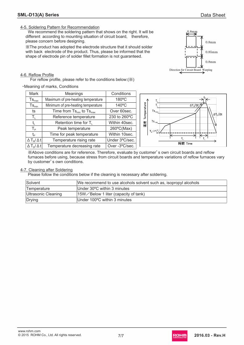
4-5. Soldering Pattern for RecommendationWe recommend the soldering pattern that shows on the right. It will be
different according to mounting situation of circuit board, therefore, please concern before designing.※The product has adopted the electrode structure that it should solder with back electrode of the product. Thus, please be informed that the shape of electrode pin of solder fillet formation is not guaranteed.
4-6. Reflow Profile For reflow profile, please refer to the conditions below:(※)
・Meaning of marks, Conditions
Mark Meanings ConditionsTsmax Maximum of pre-heating temperature 180ºCTsmin Minimum of pre-heating temperature 140ºC
ts Time from Tsmin to Tsmax Over 60sec.TL Reference temperature 230 to 260ºCtL Retention time for TL Within 40sec.TP Peak temperature 260ºC(Max)tP Time for peak temperature Within 10sec.
ΔTR/Δt Temperature rising rate Under 3ºC/sec.ΔTD/Δt Temperature decreasing rate Over -3ºC/sec.※Above conditions are for reference. Therefore, evaluate by customer’s own circuit boards and reflow furnaces before using, because stress from circuit boards and temperature variations of reflow furnaces vary by customer’s own conditions.
4-7. Cleaning after SolderingPlease follow the conditions below if the cleaning is necessary after soldering.
Solvent We recommend to use alcohols solvent such as, isopropyl alcoholsTemperature Under 30ºC within 3 minutesUltrasonic Cleaning 15W/Below 1 liter (capacity of tank)Drying Under 100ºC within 3 minutes
R1102Awww.rohm.com© 2015 ROHM Co., Ltd. All rights reserved.
Notice
ROHM Customer Support System http://www.rohm.com/contact/
Thank you for your accessing to ROHM product informations. More detail product informations and catalogs are available, please contact us.
N o t e s The information contained herein is subject to change without notice.
Before you use our Products, please contact our sales representative and verify the latest specifica-tions :
Although ROHM is continuously working to improve product reliability and quality, semicon-ductors can break down and malfunction due to various factors.Therefore, in order to prevent personal injury or fire arising from failure, please take safety measures such as complying with the derating characteristics, implementing redundant and fire prevention designs, and utilizing backups and fail-safe procedures. ROHM shall have no responsibility for any damages arising out of the use of our Poducts beyond the rating specified by ROHM.
Examples of application circuits, circuit constants and any other information contained herein are provided only to illustrate the standard usage and operations of the Products. The peripheral conditions must be taken into account when designing circuits for mass production.
The technical information specified herein is intended only to show the typical functions of and examples of application circuits for the Products. ROHM does not grant you, explicitly or implicitly, any license to use or exercise intellectual property or other rights held by ROHM or any other parties. ROHM shall have no responsibility whatsoever for any dispute arising out of the use of such technical information.
The Products are intended for use in general electronic equipment (i.e. AV/OA devices, communi-cation, consumer systems, gaming/entertainment sets) as well as the applications indicated in this document.
The Products specified in this document are not designed to be radiation tolerant.
For use of our Products in applications requiring a high degree of reliability (as exemplified below), please contact and consult with a ROHM representative : transportation equipment (i.e. cars, ships, trains), primary communication equipment, traffic lights, fire/crime prevention, safety equipment, medical systems, servers, solar cells, and power transmission systems.
Do not use our Products in applications requiring extremely high reliability, such as aerospace equipment, nuclear power control systems, and submarine repeaters.
ROHM shall have no responsibility for any damages or injury arising from non-compliance with the recommended usage conditions and specifications contained herein.
ROHM has used reasonable care to ensur the accuracy of the information contained in this document. However, ROHM does not warrants that such information is error-free, and ROHM shall have no responsibility for any damages arising from any inaccuracy or misprint of such information.
Please use the Products in accordance with any applicable environmental laws and regulations, such as the RoHS Directive. For more details, including RoHS compatibility, please contact a ROHM sales office. ROHM shall have no responsibility for any damages or losses resulting non-compliance with any applicable laws or regulations.
When providing our Products and technologies contained in this document to other countries, you must abide by the procedures and provisions stipulated in all applicable export laws and regulations, including without limitation the US Export Administration Regulations and the Foreign Exchange and Foreign Trade Act.
This document, in part or in whole, may not be reprinted or reproduced without prior consent of ROHM.
1)
2)
3)
4)
5)
6)
7)
8)
9)
10)
11)
12)
13)
14)
Mouser Electronics
Authorized Distributor
Click to View Pricing, Inventory, Delivery & Lifecycle Information: ROHM Semiconductor:
SML-D13FWT86