Embed Size (px)
Citation preview
SMIPS Processor Specification6.S195 Computer Architecture Laboratory
Fall 2012
SMIPS is the version of the MIPS instruction set architecture (ISA) we’ll be using for the processors weimplement in 6.884. SMIPS stands for Simple MIPS since it is actually a subset of the full MIPS ISA.The MIPS architecture was one of the first commercial RISC (reduced instruction set computer) processors,and grew out of the earlier MIPS research project at Stanford University. MIPS stood for Microprocessorwithout Interlocking Pipeline Stages and the goal was to simplify the machine pipeline by requiring thecompiler to schedule around pipeline hazards including a branch delay slot and a load delay slot. Today,MIPS CPUs are used in a wide range of devices: Casio builds handheld PDAs using MIPS CPUs, Sonyuses two MIPS CPUs in the Playstation-2, many Cisco internet routers contain MIPS CPUs, and SiliconGraphics makes Origin supercomputers containing up to 512 MIPS processors sharing a common memory.MIPS implementations probably span the widest range for any commercial ISA, from simple single-issuein-order pipelines to quad-issue out-of-order superscalar processors.
There are several variants of the MIPS ISA. The ISA has evolved from the original 32-bit MIPS-I archi-tecture used in the MIPS R2000 processor which appeared in 1986. The MIPS-II architecture added a fewmore instructions while retaining a 32-bit address space. The MIPS-II architecture also added hardware in-terlocks for the load delay slot. In practice, compilers couldn’t fill enough of the load delay slots with usefulwork and the NOPs in the load delay slots wasted instruction cache space. (Removing the branch delay slotsmight also have been a good idea, but would have required a second set of branch instruction encodings toremain backwards compatible.) The MIPS- III architecture debuted with the MIPS R4000 processor, andthis extended the address space to 64 bits while leaving the original 32-bit architecture as a proper subset.The MIPS-IV architecture was developed by Silicon Graphics to add many enhancements for floating-pointcomputations and appeared first in the MIPS R8000 and later in the MIPS R10000. Over the course oftime, the MIPS architecture has been widely extended, occasionally in non-compatible ways, by differentprocessor implementors. MIPS Technologies, who now own the architecture, are trying to rationalize thearchitecture into two broad groupings: MIPS32 is the 32-bit address space version, MIPS64 is the 64-bitaddress space version. There is also MIPS16, which is a compact encoding of MIPS32 that only uses 16bits for each instruction. You can find a complete description of the MIPS instruction set at the MIPS Tech-nologies web site [2] or in the book by Kane and Heinrich [3]. The book by Sweetman also explains MIPSprogramming [4]. Another source of MIPS details and implementation ideas is Computer Organization andDesign: The Hardware/Software Interface [1].
The SMIPS CPU implements a subset of the MIPS32 ISA. It does not include floating point instructions,trap instructions, misaligned load/stores, branch and link instructions, or branch likely instructions. Thereare three SMIPS variants which are discussed in more detail at the end of this document. SMIPSv1 hasonly five instructions and it is mainly used as a toy ISA for instructional SMIPSv2 includes the basic inte-
SMIPS Specification, Fall 2012. 2
ger, memory, and control instructions. It excludes multiply instructions, divide instructions, byte/halfwordloads/stores, and instructions which cause arithmetic overflows. Neither SMIPSv1 or SMIPSv2 supportexceptions, interrupts, or most of the system coprocessor. SMIPSv3 is the full SMIPS ISA and includeseverything described in this document.
1 Basic Architecture
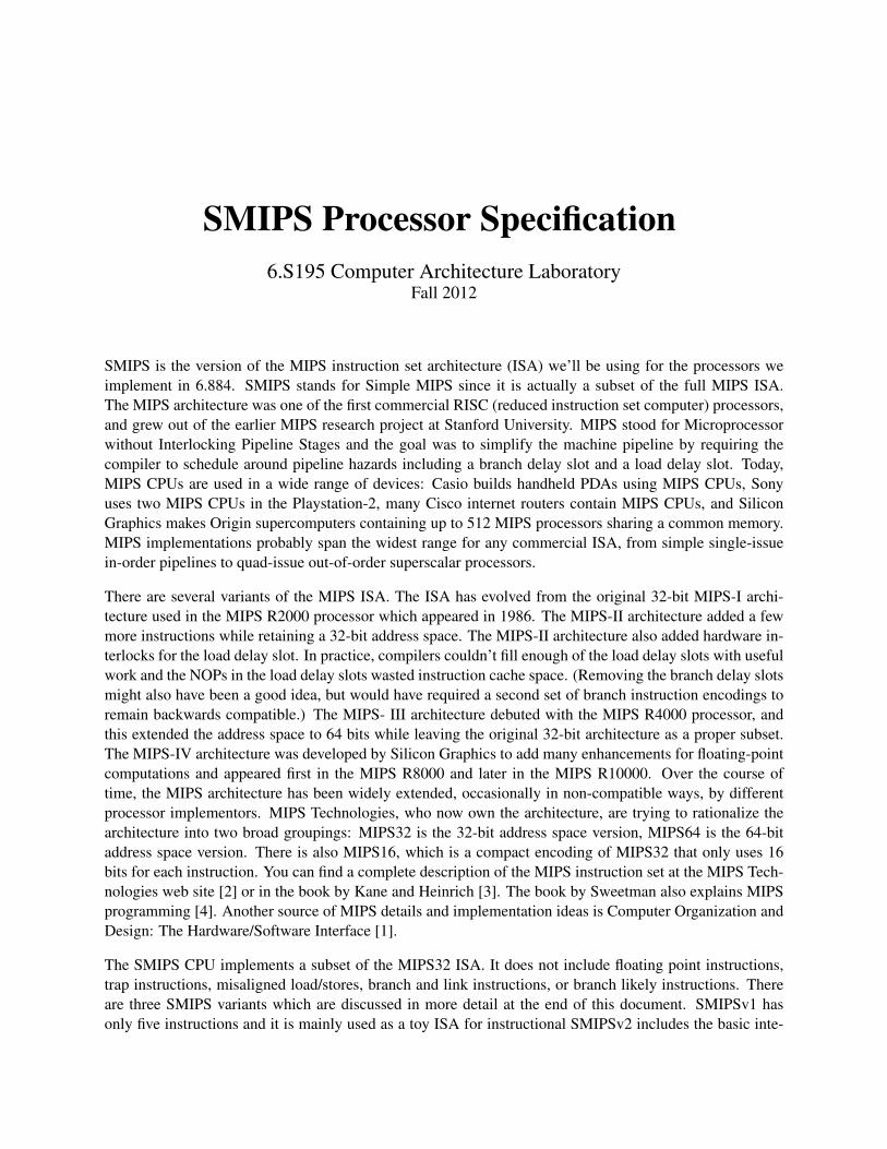
Figure 1 shows the programmer visible state in the CPU. There are 31 general purpose 32-bit registers r1–r31. Register r0 is hardwired to the constant 0. There are three special registers defined in the architecture:two registers hi and lo are used to hold the results of integer multiplies and divides, and the programcounter pc holds the address of the instruction to be executed next. These special registers are used ormodified implicitly by certain instructions.
SMIPS differs significantly from the MIPS32 ISA in one very important respect. SMIPS does not havea programmer-visible branch delay slot. Although this slightly complicates the control logic required insimple SMIPS pipelines, it greatly simplifies the design of more sophisticated out-of- order and superscalarprocessors. As in MIPS32, Loads are fully interlocked and thus there is no programmer-visible load delayslot.
Multiply instructions perform 32-bit×32-bit → 64-bit signed or unsigned integer multiplies placing theresult in the hi and lo registers. Divide instructions perform a 32-bit/32-bit signed or unsigned dividereturning both a 32-bit integer quotient and a 32-bit remainder. Integer multiplies and divides can proceedin parallel with other instructions provided the hi and lo registers are not read.
The SMIPS CPU has two operating modes: user mode and kernel mode. The current operating mode isstored in the KUC bit in the system coprocessor (COP0) status register. The CPU normally operates inuser mode until an exception forces a switch into kernel mode. The CPU will then normally execute anexception handler in kernel mode before executing a Restore From Exception (RFE) instruction to return touser mode.
Figure 1: SMIPS CPU registers
SMIPS Specification, Fall 2012. 3
2 System Control Coprocessor (CP0)
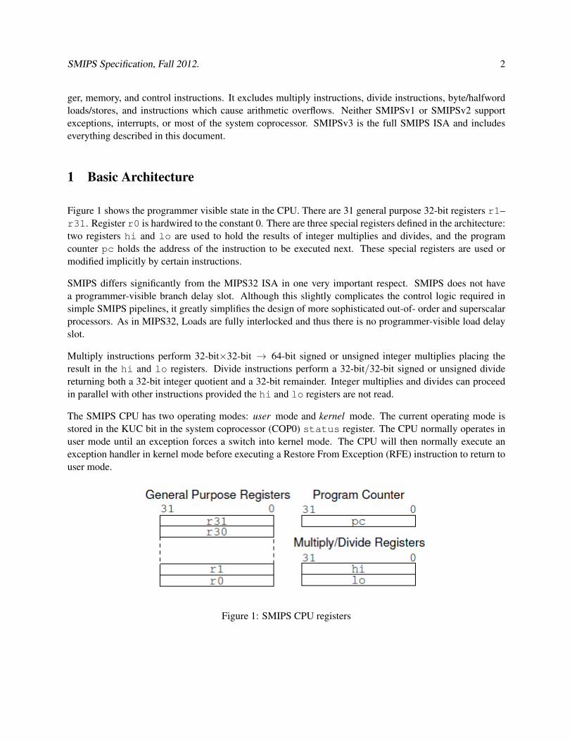
The SMIPS system control coprocessor contains a number of registers used for exception handling, commu-nication with a test rig, and the counter/timer. These registers are read and written using the MIPS standardMFC0 and MTC0 instructions respectively. User mode can access the system control coprocessor only ifthe cu[0] bit is set in the status register. Kernel mode can always access CP0, regardless of the settingof the cu[0] bit. CP0 control registers are listed in Table 1.
Number Register Description0–7 unused.
8 badvaddr Bad virtual address.9 count Counter/timer register.
10 unused.11 compare Timer compare register.12 status Status register.13 cause Cause of last exception.14 epc Exception program counter.
15–19 unused.20 fromhost Test input register.21 tohost Test output register.
22–31 unused.
Table 1: CP0 control registers.
2.1 Test Communication Registers
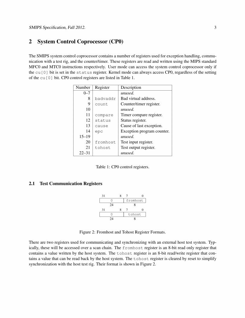
31 8 7 00 fromhost24 8
31 8 7 00 tohost24 8
Figure 2: Fromhost and Tohost Register Formats.
There are two registers used for communicating and synchronizing with an external host test system. Typ-ically, these will be accessed over a scan chain. The fromhost register is an 8-bit read only register thatcontains a value written by the host system. The tohost register is an 8-bit read/write register that con-tains a value that can be read back by the host system. The tohost register is cleared by reset to simplifysynchronization with the host test rig. Their format is shown in Figure 2.
SMIPS Specification, Fall 2012. 4
31 0count
3231 0
compare32
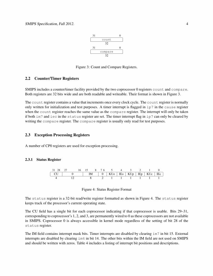
Figure 3: Count and Compare Registers.
2.2 Counter/Timer Registers
SMIPS includes a counter/timer facility provided by the two coprocessor 0 registers count and compare.Both registers are 32 bits wide and are both readable and writeable. Their format is shown in Figure 3.
The count register contains a value that increments once every clock cycle. The count register is normallyonly written for initialization and test purposes. A timer interrupt is flagged in ip7 in the cause registerwhen the count register reaches the same value as the compare register. The interrupt will only be takenif both im7 and iec in the status register are set. The timer interrupt flag in ip7 can only be cleared bywriting the compare register. The compare register is usually only read for test purposes.
2.3 Exception Processing Registers
A number of CP0 registers are used for exception processing.
2.3.1 Status Register
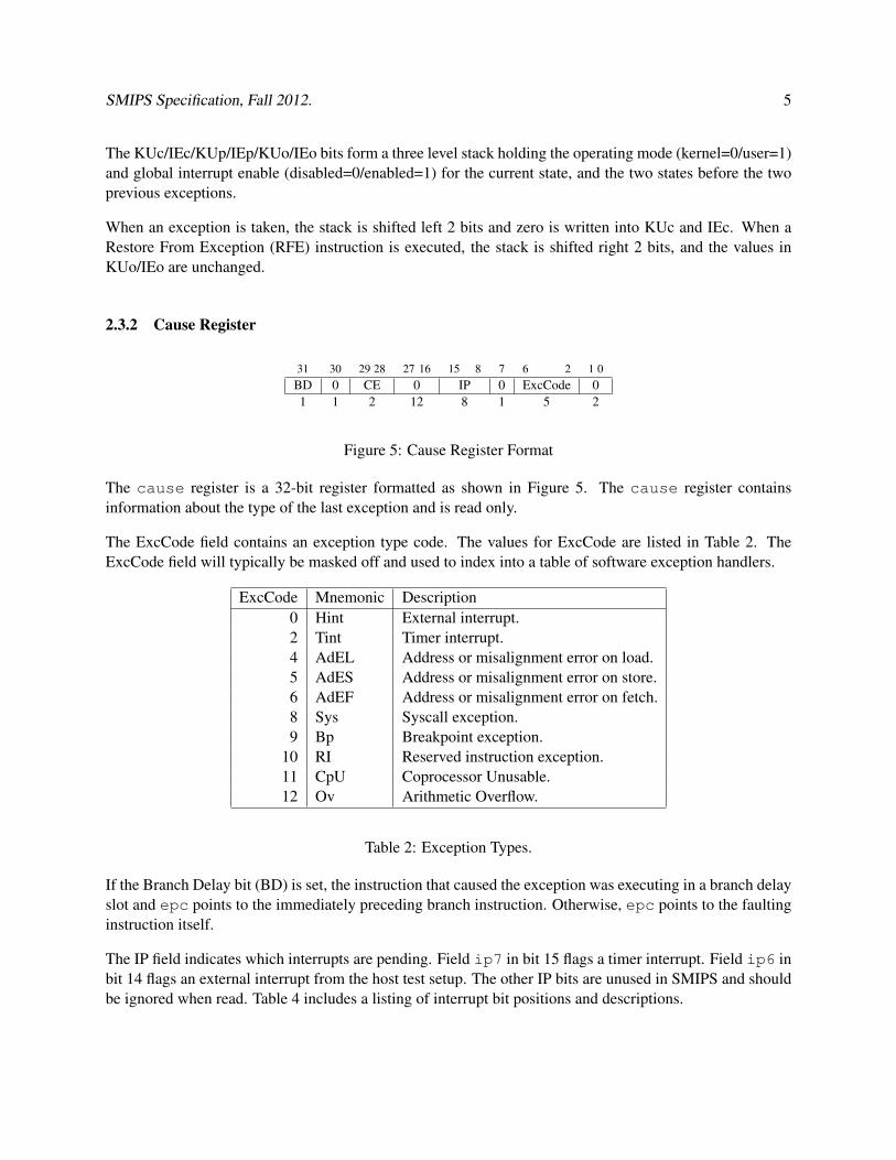
31 28 27 16 15 8 7 6 5 4 3 2 1 0CU 0 IM 0 KUo IEo KUp IEp KUc IEc4 12 8 2 1 1 1 1 1 1
Figure 4: Status Register Format
The status register is a 32-bit read/write register formatted as shown in Figure 4. The status registerkeeps track of the processor’s current operating state.
The CU field has a single bit for each coprocessor indicating if that coprocessor is usable. Bits 29–31,corresponding to coprocessor’s 1, 2, and 3, are permanently wired to 0 as these coprocessors are not availablein SMIPS. Coprocessor 0 is always accessible in kernel mode regardless of the setting of bit 28 of thestatus register.
The IM field contains interrupt mask bits. Timer interrupts are disabled by clearing im7 in bit 15. Externalinterrupts are disabled by clearing im6 in bit 14. The other bits within the IM field are not used on SMIPSand should be written with zeros. Table 4 includes a listing of interrupt bit positions and descriptions.
SMIPS Specification, Fall 2012. 5
The KUc/IEc/KUp/IEp/KUo/IEo bits form a three level stack holding the operating mode (kernel=0/user=1)and global interrupt enable (disabled=0/enabled=1) for the current state, and the two states before the twoprevious exceptions.
When an exception is taken, the stack is shifted left 2 bits and zero is written into KUc and IEc. When aRestore From Exception (RFE) instruction is executed, the stack is shifted right 2 bits, and the values inKUo/IEo are unchanged.
2.3.2 Cause Register
31 30 29 28 27 16 15 8 7 6 2 1 0BD 0 CE 0 IP 0 ExcCode 01 1 2 12 8 1 5 2
Figure 5: Cause Register Format
The cause register is a 32-bit register formatted as shown in Figure 5. The cause register containsinformation about the type of the last exception and is read only.
The ExcCode field contains an exception type code. The values for ExcCode are listed in Table 2. TheExcCode field will typically be masked off and used to index into a table of software exception handlers.
ExcCode Mnemonic Description0 Hint External interrupt.2 Tint Timer interrupt.4 AdEL Address or misalignment error on load.5 AdES Address or misalignment error on store.6 AdEF Address or misalignment error on fetch.8 Sys Syscall exception.9 Bp Breakpoint exception.
10 RI Reserved instruction exception.11 CpU Coprocessor Unusable.12 Ov Arithmetic Overflow.
Table 2: Exception Types.
If the Branch Delay bit (BD) is set, the instruction that caused the exception was executing in a branch delayslot and epc points to the immediately preceding branch instruction. Otherwise, epc points to the faultinginstruction itself.
The IP field indicates which interrupts are pending. Field ip7 in bit 15 flags a timer interrupt. Field ip6 inbit 14 flags an external interrupt from the host test setup. The other IP bits are unused in SMIPS and shouldbe ignored when read. Table 4 includes a listing of interrupt bit positions and descriptions.
SMIPS Specification, Fall 2012. 6
2.3.3 Exception Program Counter
31 0epc
32
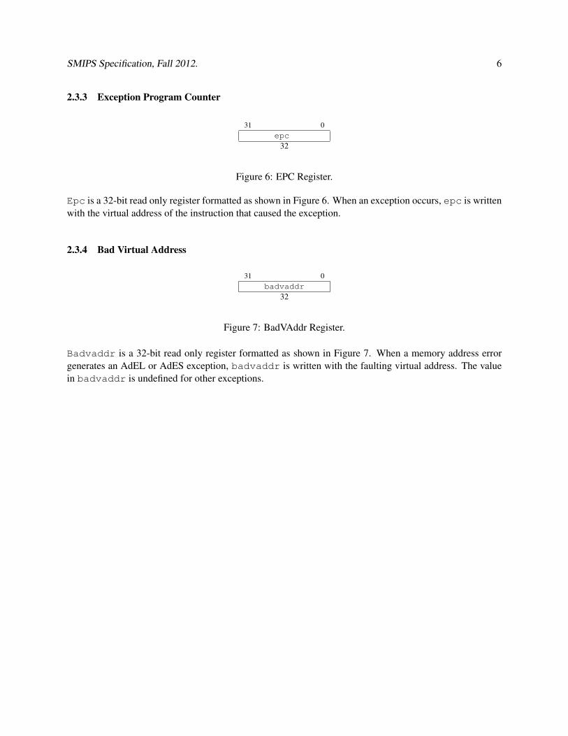
Figure 6: EPC Register.
Epc is a 32-bit read only register formatted as shown in Figure 6. When an exception occurs, epc is writtenwith the virtual address of the instruction that caused the exception.
2.3.4 Bad Virtual Address
31 0badvaddr
32
Figure 7: BadVAddr Register.
Badvaddr is a 32-bit read only register formatted as shown in Figure 7. When a memory address errorgenerates an AdEL or AdES exception, badvaddr is written with the faulting virtual address. The valuein badvaddr is undefined for other exceptions.
SMIPS Specification, Fall 2012. 7
3 Addressing and Memory Protection
SMIPS has a full 32-bit virtual address space with a full 32-bit physical address space. Sub-word dataaddressing is big-endian on SMIPS.
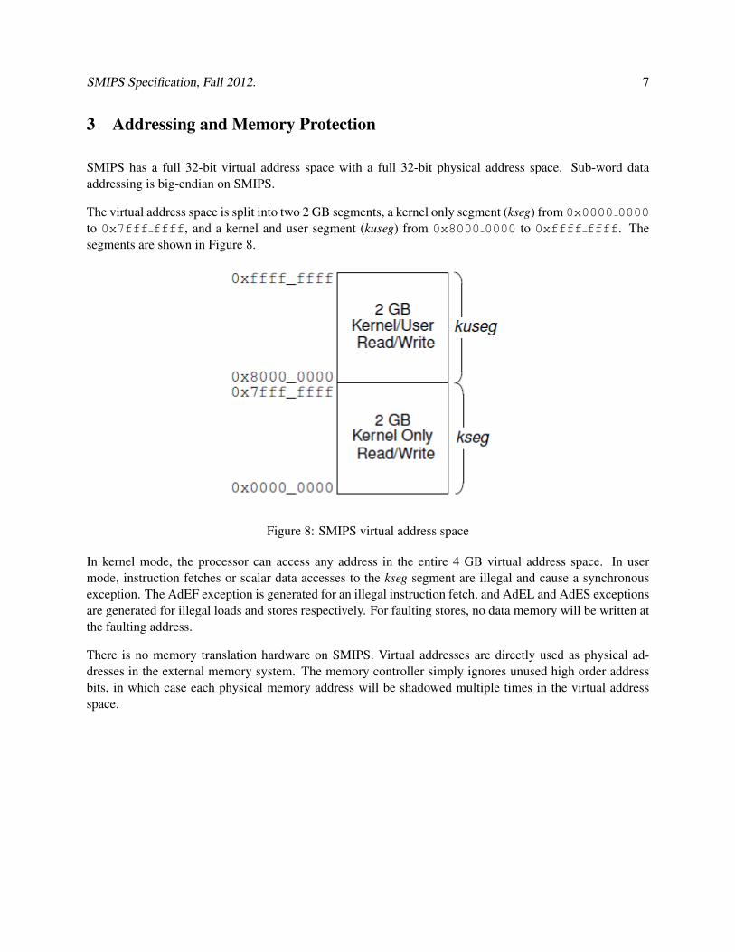
The virtual address space is split into two 2 GB segments, a kernel only segment (kseg) from 0x0000 0000to 0x7fff ffff, and a kernel and user segment (kuseg) from 0x8000 0000 to 0xffff ffff. Thesegments are shown in Figure 8.
Figure 8: SMIPS virtual address space
In kernel mode, the processor can access any address in the entire 4 GB virtual address space. In usermode, instruction fetches or scalar data accesses to the kseg segment are illegal and cause a synchronousexception. The AdEF exception is generated for an illegal instruction fetch, and AdEL and AdES exceptionsare generated for illegal loads and stores respectively. For faulting stores, no data memory will be written atthe faulting address.
There is no memory translation hardware on SMIPS. Virtual addresses are directly used as physical ad-dresses in the external memory system. The memory controller simply ignores unused high order addressbits, in which case each physical memory address will be shadowed multiple times in the virtual addressspace.
SMIPS Specification, Fall 2012. 8
4 Reset, Interrupt, and Exception Processing
There are three possible sources of disruption to normal program flow: reset, interrupts (asynchronous ex-ceptions), and synchronous exceptions. Reset and interrupts occur asynchronously to the executing programand can be considered to occur between instructions. Synchronous exceptions occur during execution of aparticular instruction.
If more than one of these classes of event occurs on a given cycle, reset has highest priority, and all interruptshave priority over all synchronous exceptions. The tables below show the priorities of different types ofinterrupt and synchronous exception.
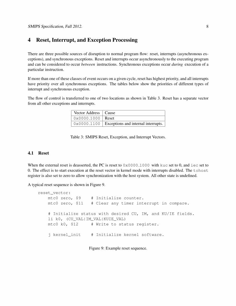
The flow of control is transferred to one of two locations as shown in Table 3. Reset has a separate vectorfrom all other exceptions and interrupts.
Vector Address Cause0x0000 1000 Reset0x0000 1100 Exceptions and internal interrupts.
Table 3: SMIPS Reset, Exception, and Interrupt Vectors.
4.1 Reset
When the external reset is deasserted, the PC is reset to 0x0000 1000 with kuc set to 0, and iec set to0. The effect is to start execution at the reset vector in kernel mode with interrupts disabled. The tohostregister is also set to zero to allow synchronization with the host system. All other state is undefined.
A typical reset sequence is shown in Figure 9.
reset_vector:mtc0 zero, $9 # Initialize counter.mtc0 zero, $11 # Clear any timer interrupt in compare.
# Initialize status with desired CU, IM, and KU/IE fields.li k0, (CU_VAL|IM_VAL|KUIE_VAL)mtc0 k0, $12 # Write to status register.
j kernel_init # Initialize kernel software.
Figure 9: Example reset sequence.
SMIPS Specification, Fall 2012. 9
4.2 Interrupts
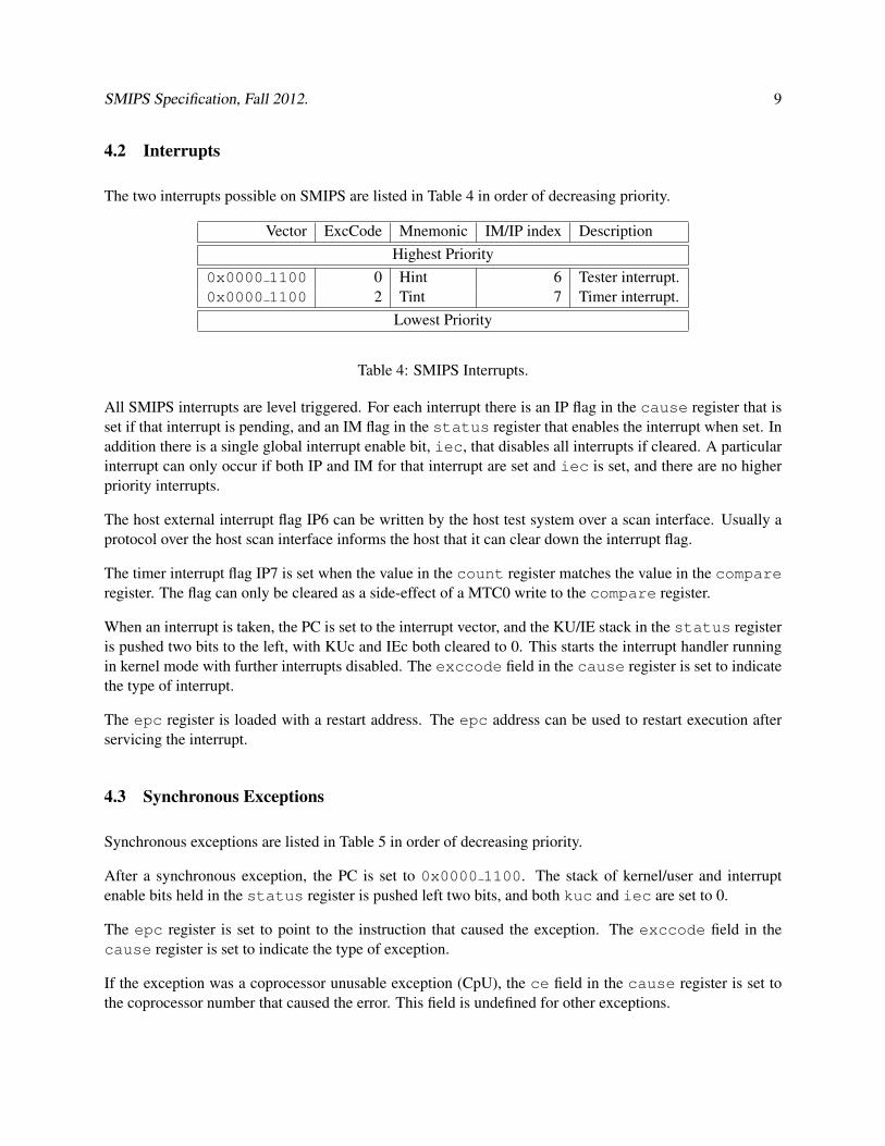
The two interrupts possible on SMIPS are listed in Table 4 in order of decreasing priority.
Vector ExcCode Mnemonic IM/IP index DescriptionHighest Priority
0x0000 1100 0 Hint 6 Tester interrupt.0x0000 1100 2 Tint 7 Timer interrupt.
Lowest Priority
Table 4: SMIPS Interrupts.
All SMIPS interrupts are level triggered. For each interrupt there is an IP flag in the cause register that isset if that interrupt is pending, and an IM flag in the status register that enables the interrupt when set. Inaddition there is a single global interrupt enable bit, iec, that disables all interrupts if cleared. A particularinterrupt can only occur if both IP and IM for that interrupt are set and iec is set, and there are no higherpriority interrupts.
The host external interrupt flag IP6 can be written by the host test system over a scan interface. Usually aprotocol over the host scan interface informs the host that it can clear down the interrupt flag.
The timer interrupt flag IP7 is set when the value in the count register matches the value in the compareregister. The flag can only be cleared as a side-effect of a MTC0 write to the compare register.
When an interrupt is taken, the PC is set to the interrupt vector, and the KU/IE stack in the status registeris pushed two bits to the left, with KUc and IEc both cleared to 0. This starts the interrupt handler runningin kernel mode with further interrupts disabled. The exccode field in the cause register is set to indicatethe type of interrupt.
The epc register is loaded with a restart address. The epc address can be used to restart execution afterservicing the interrupt.
4.3 Synchronous Exceptions
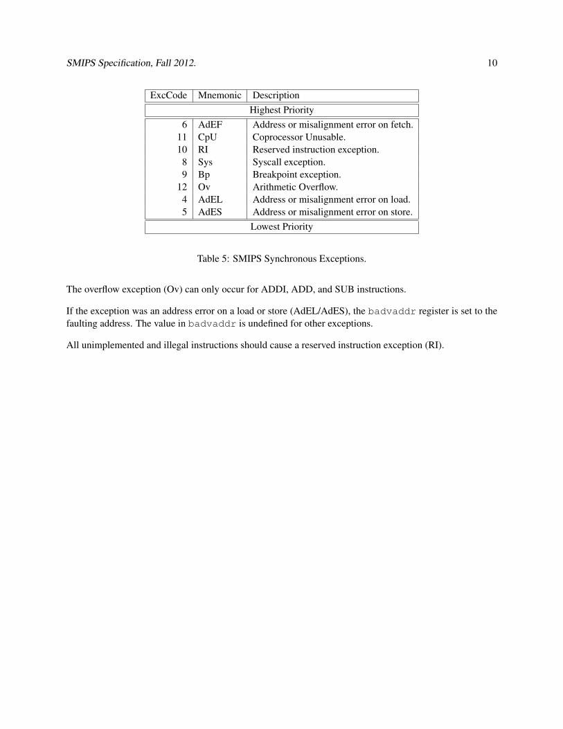
Synchronous exceptions are listed in Table 5 in order of decreasing priority.
After a synchronous exception, the PC is set to 0x0000 1100. The stack of kernel/user and interruptenable bits held in the status register is pushed left two bits, and both kuc and iec are set to 0.
The epc register is set to point to the instruction that caused the exception. The exccode field in thecause register is set to indicate the type of exception.
If the exception was a coprocessor unusable exception (CpU), the ce field in the cause register is set tothe coprocessor number that caused the error. This field is undefined for other exceptions.
SMIPS Specification, Fall 2012. 10
ExcCode Mnemonic DescriptionHighest Priority
6 AdEF Address or misalignment error on fetch.11 CpU Coprocessor Unusable.10 RI Reserved instruction exception.
8 Sys Syscall exception.9 Bp Breakpoint exception.
12 Ov Arithmetic Overflow.4 AdEL Address or misalignment error on load.5 AdES Address or misalignment error on store.
Lowest Priority
Table 5: SMIPS Synchronous Exceptions.
The overflow exception (Ov) can only occur for ADDI, ADD, and SUB instructions.
If the exception was an address error on a load or store (AdEL/AdES), the badvaddr register is set to thefaulting address. The value in badvaddr is undefined for other exceptions.
All unimplemented and illegal instructions should cause a reserved instruction exception (RI).
SMIPS Specification, Fall 2012. 11
5 Instruction Encodings
SMIPS uses the standard MIPS instruction set.
5.1 Instruction Formats
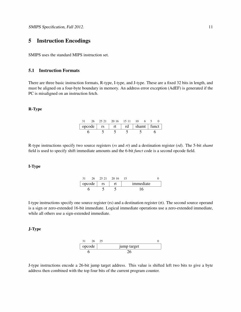
There are three basic instruction formats, R-type, I-type, and J-type. These are a fixed 32 bits in length, andmust be aligned on a four-byte boundary in memory. An address error exception (AdEF) is generated if thePC is misaligned on an instruction fetch.
R-Type
31 26 25 21 20 16 15 11 10 6 5 0
opcode rs rt rd shamt funct6 5 5 5 5 6
R-type instructions specify two source registers (rs and rt) and a destination register (rd). The 5-bit shamtfield is used to specify shift immediate amounts and the 6-bit funct code is a second opcode field.
I-Type
31 26 25 21 20 16 15 0
opcode rs rt immediate6 5 5 16
I-type instructions specify one source register (rs) and a destination register (rt). The second source operandis a sign or zero-extended 16-bit immediate. Logical immediate operations use a zero-extended immediate,while all others use a sign-extended immediate.
J-Type
31 26 25 0
opcode jump target6 26
J-type instructions encode a 26-bit jump target address. This value is shifted left two bits to give a byteaddress then combined with the top four bits of the current program counter.
SMIPS Specification, Fall 2012. 12
5.2 Instruction Categories
MIPS instructions can be grouped into several basic categories: loads and stores, computation instructions,branch and jump instructions, and coprocessor instructions.
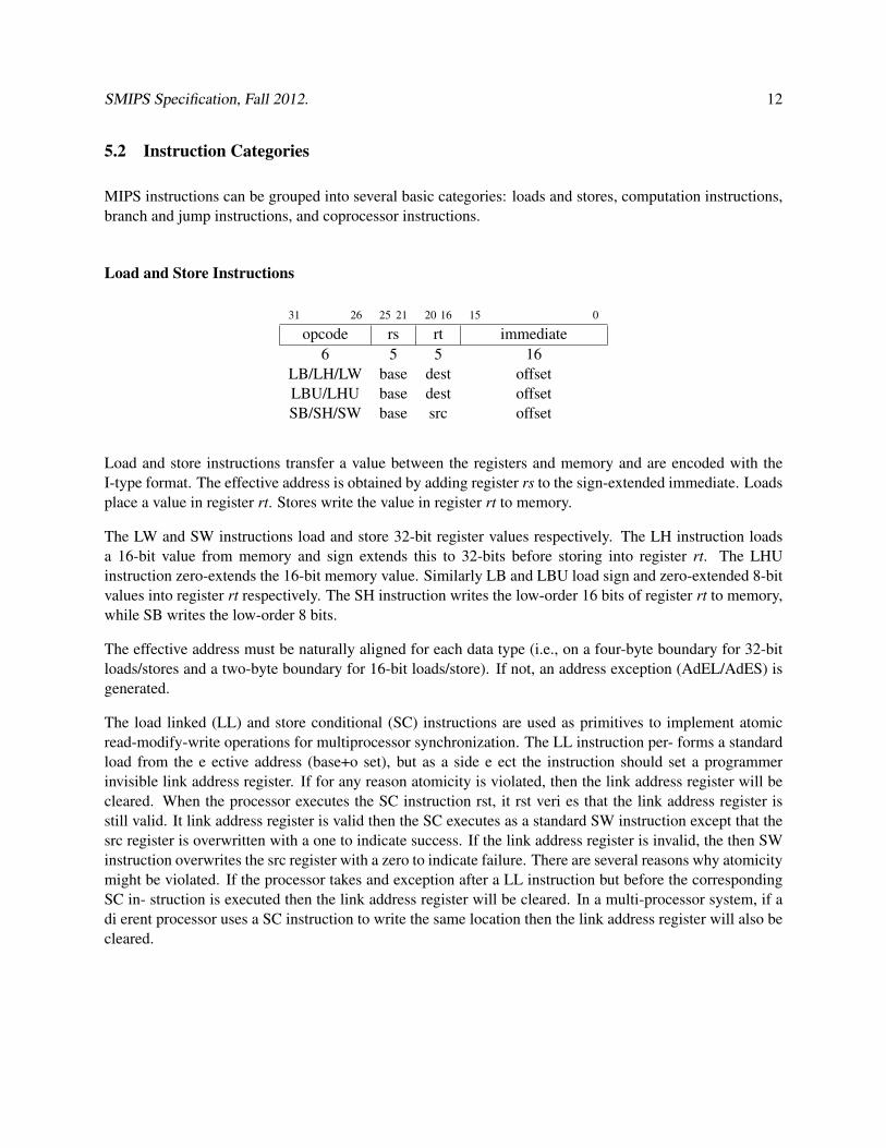
Load and Store Instructions
31 26 25 21 20 16 15 0
opcode rs rt immediate6 5 5 16
LB/LH/LW base dest offsetLBU/LHU base dest offsetSB/SH/SW base src offset
Load and store instructions transfer a value between the registers and memory and are encoded with theI-type format. The effective address is obtained by adding register rs to the sign-extended immediate. Loadsplace a value in register rt. Stores write the value in register rt to memory.
The LW and SW instructions load and store 32-bit register values respectively. The LH instruction loadsa 16-bit value from memory and sign extends this to 32-bits before storing into register rt. The LHUinstruction zero-extends the 16-bit memory value. Similarly LB and LBU load sign and zero-extended 8-bitvalues into register rt respectively. The SH instruction writes the low-order 16 bits of register rt to memory,while SB writes the low-order 8 bits.
The effective address must be naturally aligned for each data type (i.e., on a four-byte boundary for 32-bitloads/stores and a two-byte boundary for 16-bit loads/store). If not, an address exception (AdEL/AdES) isgenerated.
The load linked (LL) and store conditional (SC) instructions are used as primitives to implement atomicread-modify-write operations for multiprocessor synchronization. The LL instruction per- forms a standardload from the e ective address (base+o set), but as a side e ect the instruction should set a programmerinvisible link address register. If for any reason atomicity is violated, then the link address register will becleared. When the processor executes the SC instruction rst, it rst veri es that the link address register isstill valid. It link address register is valid then the SC executes as a standard SW instruction except that thesrc register is overwritten with a one to indicate success. If the link address register is invalid, the then SWinstruction overwrites the src register with a zero to indicate failure. There are several reasons why atomicitymight be violated. If the processor takes and exception after a LL instruction but before the correspondingSC in- struction is executed then the link address register will be cleared. In a multi-processor system, if adi erent processor uses a SC instruction to write the same location then the link address register will also becleared.
SMIPS Specification, Fall 2012. 13
Computational Instructions
Computational instructions are either encoded as register-immediate operations using the I-type format oras register-register operations using the R-type format. The destination is register rt for register-immediateinstructions and rd for register-register instructions.
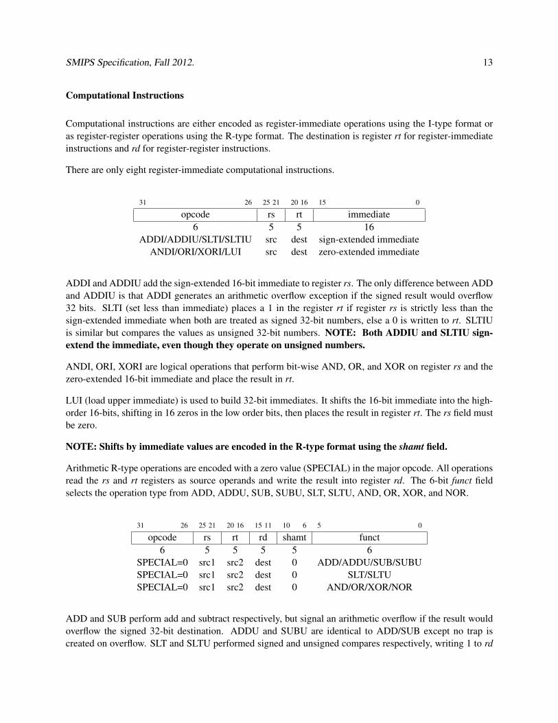
There are only eight register-immediate computational instructions.
31 26 25 21 20 16 15 0
opcode rs rt immediate6 5 5 16
ADDI/ADDIU/SLTI/SLTIU src dest sign-extended immediateANDI/ORI/XORI/LUI src dest zero-extended immediate
ADDI and ADDIU add the sign-extended 16-bit immediate to register rs. The only difference between ADDand ADDIU is that ADDI generates an arithmetic overflow exception if the signed result would overflow32 bits. SLTI (set less than immediate) places a 1 in the register rt if register rs is strictly less than thesign-extended immediate when both are treated as signed 32-bit numbers, else a 0 is written to rt. SLTIUis similar but compares the values as unsigned 32-bit numbers. NOTE: Both ADDIU and SLTIU sign-extend the immediate, even though they operate on unsigned numbers.
ANDI, ORI, XORI are logical operations that perform bit-wise AND, OR, and XOR on register rs and thezero-extended 16-bit immediate and place the result in rt.
LUI (load upper immediate) is used to build 32-bit immediates. It shifts the 16-bit immediate into the high-order 16-bits, shifting in 16 zeros in the low order bits, then places the result in register rt. The rs field mustbe zero.
NOTE: Shifts by immediate values are encoded in the R-type format using the shamt field.
Arithmetic R-type operations are encoded with a zero value (SPECIAL) in the major opcode. All operationsread the rs and rt registers as source operands and write the result into register rd. The 6-bit funct fieldselects the operation type from ADD, ADDU, SUB, SUBU, SLT, SLTU, AND, OR, XOR, and NOR.
31 26 25 21 20 16 15 11 10 6 5 0
opcode rs rt rd shamt funct6 5 5 5 5 6
SPECIAL=0 src1 src2 dest 0 ADD/ADDU/SUB/SUBUSPECIAL=0 src1 src2 dest 0 SLT/SLTUSPECIAL=0 src1 src2 dest 0 AND/OR/XOR/NOR
ADD and SUB perform add and subtract respectively, but signal an arithmetic overflow if the result wouldoverflow the signed 32-bit destination. ADDU and SUBU are identical to ADD/SUB except no trap iscreated on overflow. SLT and SLTU performed signed and unsigned compares respectively, writing 1 to rd
SMIPS Specification, Fall 2012. 14
if rs < rt, 0 otherwise. AND, OR, XOR, and NOR perform bitwise logical operations. NOTE: NOR rd,rx, rx performs a logical inversion (NOT) of register rx.
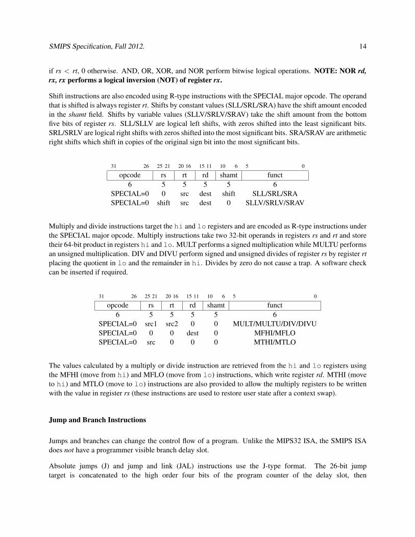
Shift instructions are also encoded using R-type instructions with the SPECIAL major opcode. The operandthat is shifted is always register rt. Shifts by constant values (SLL/SRL/SRA) have the shift amount encodedin the shamt field. Shifts by variable values (SLLV/SRLV/SRAV) take the shift amount from the bottomfive bits of register rs. SLL/SLLV are logical left shifts, with zeros shifted into the least significant bits.SRL/SRLV are logical right shifts with zeros shifted into the most significant bits. SRA/SRAV are arithmeticright shifts which shift in copies of the original sign bit into the most significant bits.
31 26 25 21 20 16 15 11 10 6 5 0
opcode rs rt rd shamt funct6 5 5 5 5 6
SPECIAL=0 0 src dest shift SLL/SRL/SRASPECIAL=0 shift src dest 0 SLLV/SRLV/SRAV
Multiply and divide instructions target the hi and lo registers and are encoded as R-type instructions underthe SPECIAL major opcode. Multiply instructions take two 32-bit operands in registers rs and rt and storetheir 64-bit product in registers hi and lo. MULT performs a signed multiplication while MULTU performsan unsigned multiplication. DIV and DIVU perform signed and unsigned divides of register rs by register rtplacing the quotient in lo and the remainder in hi. Divides by zero do not cause a trap. A software checkcan be inserted if required.
31 26 25 21 20 16 15 11 10 6 5 0
opcode rs rt rd shamt funct6 5 5 5 5 6
SPECIAL=0 src1 src2 0 0 MULT/MULTU/DIV/DIVUSPECIAL=0 0 0 dest 0 MFHI/MFLOSPECIAL=0 src 0 0 0 MTHI/MTLO
The values calculated by a multiply or divide instruction are retrieved from the hi and lo registers usingthe MFHI (move from hi) and MFLO (move from lo) instructions, which write register rd. MTHI (moveto hi) and MTLO (move to lo) instructions are also provided to allow the multiply registers to be writtenwith the value in register rs (these instructions are used to restore user state after a context swap).
Jump and Branch Instructions
Jumps and branches can change the control flow of a program. Unlike the MIPS32 ISA, the SMIPS ISAdoes not have a programmer visible branch delay slot.
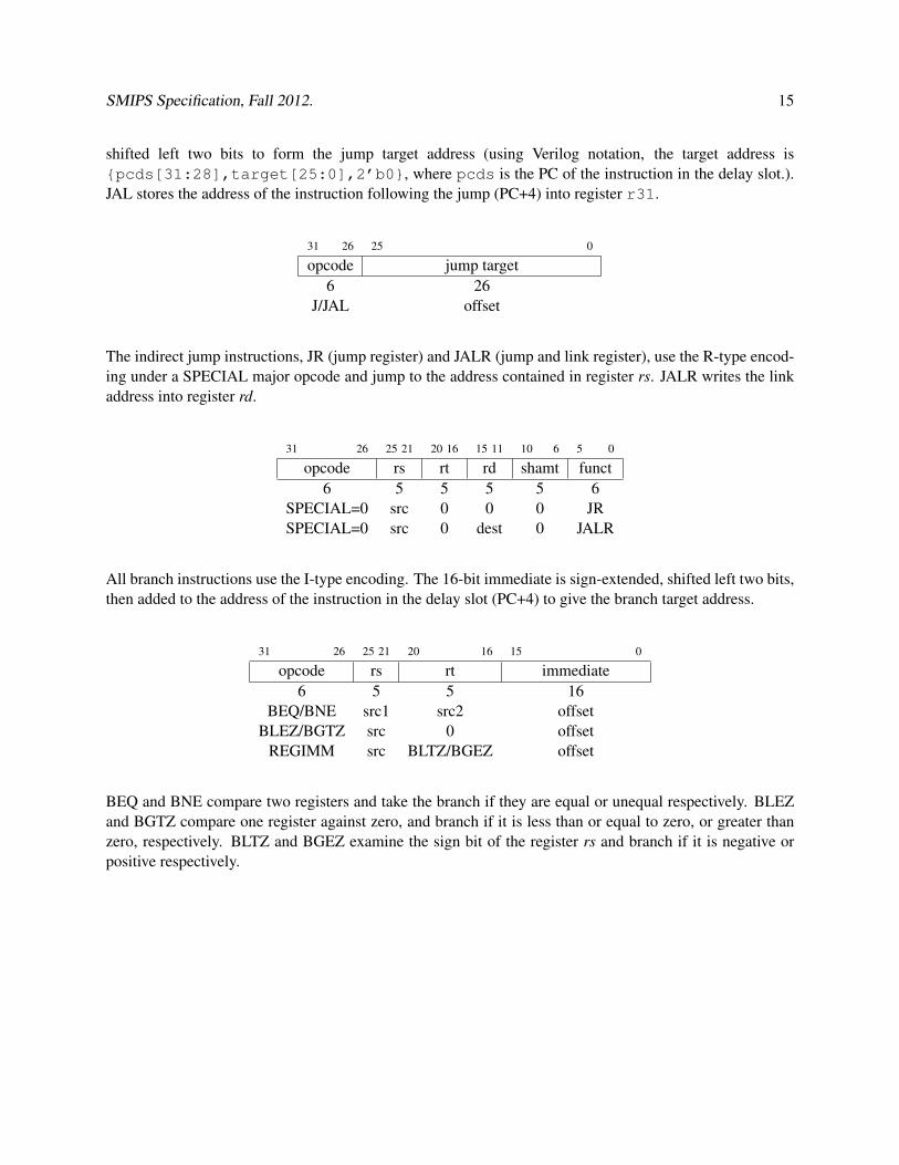
Absolute jumps (J) and jump and link (JAL) instructions use the J-type format. The 26-bit jumptarget is concatenated to the high order four bits of the program counter of the delay slot, then
SMIPS Specification, Fall 2012. 15
shifted left two bits to form the jump target address (using Verilog notation, the target address is{pcds[31:28],target[25:0],2’b0}, where pcds is the PC of the instruction in the delay slot.).JAL stores the address of the instruction following the jump (PC+4) into register r31.
31 26 25 0
opcode jump target6 26
J/JAL offset
The indirect jump instructions, JR (jump register) and JALR (jump and link register), use the R-type encod-ing under a SPECIAL major opcode and jump to the address contained in register rs. JALR writes the linkaddress into register rd.
31 26 25 21 20 16 15 11 10 6 5 0
opcode rs rt rd shamt funct6 5 5 5 5 6
SPECIAL=0 src 0 0 0 JRSPECIAL=0 src 0 dest 0 JALR
All branch instructions use the I-type encoding. The 16-bit immediate is sign-extended, shifted left two bits,then added to the address of the instruction in the delay slot (PC+4) to give the branch target address.
31 26 25 21 20 16 15 0
opcode rs rt immediate6 5 5 16
BEQ/BNE src1 src2 offsetBLEZ/BGTZ src 0 offset
REGIMM src BLTZ/BGEZ offset
BEQ and BNE compare two registers and take the branch if they are equal or unequal respectively. BLEZand BGTZ compare one register against zero, and branch if it is less than or equal to zero, or greater thanzero, respectively. BLTZ and BGEZ examine the sign bit of the register rs and branch if it is negative orpositive respectively.
SMIPS Specification, Fall 2012. 16
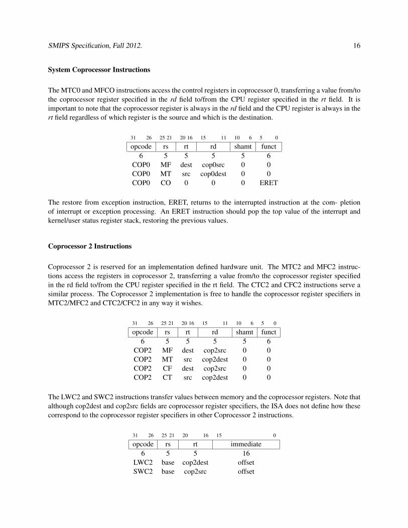
System Coprocessor Instructions
The MTC0 and MFCO instructions access the control registers in coprocessor 0, transferring a value from/tothe coprocessor register specified in the rd field to/from the CPU register specified in the rt field. It isimportant to note that the coprocessor register is always in the rd field and the CPU register is always in thert field regardless of which register is the source and which is the destination.
31 26 25 21 20 16 15 11 10 6 5 0
opcode rs rt rd shamt funct6 5 5 5 5 6
COP0 MF dest cop0src 0 0COP0 MT src cop0dest 0 0COP0 CO 0 0 0 ERET
The restore from exception instruction, ERET, returns to the interrupted instruction at the com- pletionof interrupt or exception processing. An ERET instruction should pop the top value of the interrupt andkernel/user status register stack, restoring the previous values.
Coprocessor 2 Instructions
Coprocessor 2 is reserved for an implementation defined hardware unit. The MTC2 and MFC2 instruc-tions access the registers in coprocessor 2, transferring a value from/to the coprocessor register specifiedin the rd field to/from the CPU register specified in the rt field. The CTC2 and CFC2 instructions serve asimilar process. The Coprocessor 2 implementation is free to handle the coprocessor register specifiers inMTC2/MFC2 and CTC2/CFC2 in any way it wishes.
31 26 25 21 20 16 15 11 10 6 5 0
opcode rs rt rd shamt funct6 5 5 5 5 6
COP2 MF dest cop2src 0 0COP2 MT src cop2dest 0 0COP2 CF dest cop2src 0 0COP2 CT src cop2dest 0 0
The LWC2 and SWC2 instructions transfer values between memory and the coprocessor registers. Note thatalthough cop2dest and cop2src fields are coprocessor register specifiers, the ISA does not define how thesecorrespond to the coprocessor register specifiers in other Coprocessor 2 instructions.
31 26 25 21 20 16 15 0
opcode rs rt immediate6 5 5 16
LWC2 base cop2dest offsetSWC2 base cop2src offset
SMIPS Specification, Fall 2012. 17
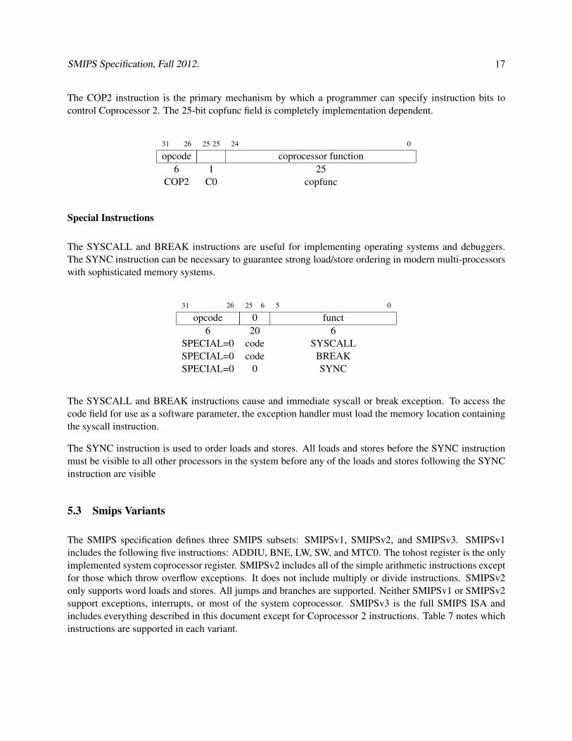
The COP2 instruction is the primary mechanism by which a programmer can specify instruction bits tocontrol Coprocessor 2. The 25-bit copfunc field is completely implementation dependent.
31 26 25 25 24 0
opcode coprocessor function6 1 25
COP2 C0 copfunc
Special Instructions
The SYSCALL and BREAK instructions are useful for implementing operating systems and debuggers.The SYNC instruction can be necessary to guarantee strong load/store ordering in modern multi-processorswith sophisticated memory systems.
31 26 25 6 5 0
opcode 0 funct6 20 6
SPECIAL=0 code SYSCALLSPECIAL=0 code BREAKSPECIAL=0 0 SYNC
The SYSCALL and BREAK instructions cause and immediate syscall or break exception. To access thecode field for use as a software parameter, the exception handler must load the memory location containingthe syscall instruction.
The SYNC instruction is used to order loads and stores. All loads and stores before the SYNC instructionmust be visible to all other processors in the system before any of the loads and stores following the SYNCinstruction are visible
5.3 Smips Variants
The SMIPS specification defines three SMIPS subsets: SMIPSv1, SMIPSv2, and SMIPSv3. SMIPSv1includes the following five instructions: ADDIU, BNE, LW, SW, and MTC0. The tohost register is the onlyimplemented system coprocessor register. SMIPSv2 includes all of the simple arithmetic instructions exceptfor those which throw overflow exceptions. It does not include multiply or divide instructions. SMIPSv2only supports word loads and stores. All jumps and branches are supported. Neither SMIPSv1 or SMIPSv2support exceptions, interrupts, or most of the system coprocessor. SMIPSv3 is the full SMIPS ISA andincludes everything described in this document except for Coprocessor 2 instructions. Table 7 notes whichinstructions are supported in each variant.
SMIPS Specification, Fall 2012. 18
5.4 Unimplemented instructions
Several instructions in the MIPS32 instruction set are not supported by the SMIPS. These instructions shouldcause a reserved instruction exception (RI) and can be emulated in software by an exception handler.
The misaligned load/store instructions, Load Word Left (LWL), Load Word Right (LWR), Store Word Left(SWL), and Store Word Right (SWR), are not implemented. A trap handler can emulate the misalignedaccess. Compilers for SMIPS should avoid generating these instructions, and should instead generate codeto perform the misaligned access using multiple aligned accesses.
The MIPS32 trap instructions, TGE, TGEU, TLT, TLTU, TEQ, TNE, TGEI, TGEIU, TLTI, TLTIU, TEQI,TNEI, are not implemented. The illegal instruction trap handler can perform the comparison and if thecondition is met jump to the appropriate exception routine, otherwise resume user mode execution after thetrap instruction. Alternatively, these instructions may be synthesized by the assembler, or simply avoidedby the compiler.
The floating point coprocessor (COP1) is not supported. All MIPS32 coprocessor 1 instructions are trappedto allow emulation of floating-point. For higher performance, compilers for SMIPS could directly generatecalls to software floating point code libraries rather than emit coprocessor instructions that will cause traps,though this will require modifying the standard MIPS calling convention.
Branch likely and branch and link instructions are not implemented and cannot be emulated so they shouldbe avoided by compilers for SMIPS.
SMIPS Specification, Fall 2012. 19
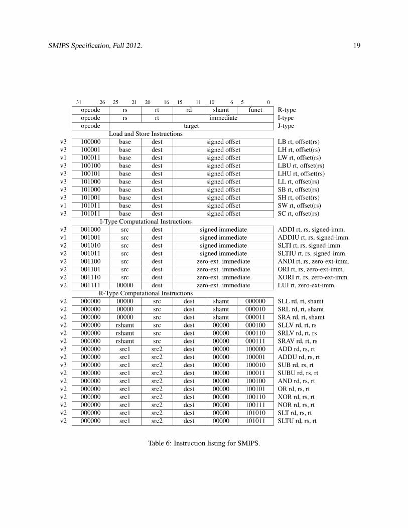
31 26 25 21 20 16 15 11 10 6 5 0opcode rs rt rd shamt funct R-typeopcode rs rt immediate I-typeopcode target J-type
Load and Store Instructionsv3 100000 base dest signed offset LB rt, offset(rs)v3 100001 base dest signed offset LH rt, offset(rs)v1 100011 base dest signed offset LW rt, offset(rs)v3 100100 base dest signed offset LBU rt, offset(rs)v3 100101 base dest signed offset LHU rt, offset(rs)v3 101000 base dest signed offset LL rt, offset(rs)v3 101000 base dest signed offset SB rt, offset(rs)v3 101001 base dest signed offset SH rt, offset(rs)v1 101011 base dest signed offset SW rt, offset(rs)v3 101011 base dest signed offset SC rt, offset(rs)
I-Type Computational Instructionsv3 001000 src dest signed immediate ADDI rt, rs, signed-imm.v1 001001 src dest signed immediate ADDIU rt, rs, signed-imm.v2 001010 src dest signed immediate SLTI rt, rs, signed-imm.v2 001011 src dest signed immediate SLTIU rt, rs, signed-imm.v2 001100 src dest zero-ext. immediate ANDI rt, rs, zero-ext-imm.v2 001101 src dest zero-ext. immediate ORI rt, rs, zero-ext-imm.v2 001110 src dest zero-ext. immediate XORI rt, rs, zero-ext-imm.v2 001111 00000 dest zero-ext. immediate LUI rt, zero-ext-imm.
R-Type Computational Instructionsv2 000000 00000 src dest shamt 000000 SLL rd, rt, shamtv2 000000 00000 src dest shamt 000010 SRL rd, rt, shamtv2 000000 00000 src dest shamt 000011 SRA rd, rt, shamtv2 000000 rshamt src dest 00000 000100 SLLV rd, rt, rsv2 000000 rshamt src dest 00000 000110 SRLV rd, rt, rsv2 000000 rshamt src dest 00000 000111 SRAV rd, rt, rsv3 000000 src1 src2 dest 00000 100000 ADD rd, rs, rtv2 000000 src1 src2 dest 00000 100001 ADDU rd, rs, rtv3 000000 src1 src2 dest 00000 100010 SUB rd, rs, rtv2 000000 src1 src2 dest 00000 100011 SUBU rd, rs, rtv2 000000 src1 src2 dest 00000 100100 AND rd, rs, rtv2 000000 src1 src2 dest 00000 100101 OR rd, rs, rtv2 000000 src1 src2 dest 00000 100110 XOR rd, rs, rtv2 000000 src1 src2 dest 00000 100111 NOR rd, rs, rtv2 000000 src1 src2 dest 00000 101010 SLT rd, rs, rtv2 000000 src1 src2 dest 00000 101011 SLTU rd, rs, rt
Table 6: Instruction listing for SMIPS.
SMIPS Specification, Fall 2012. 20
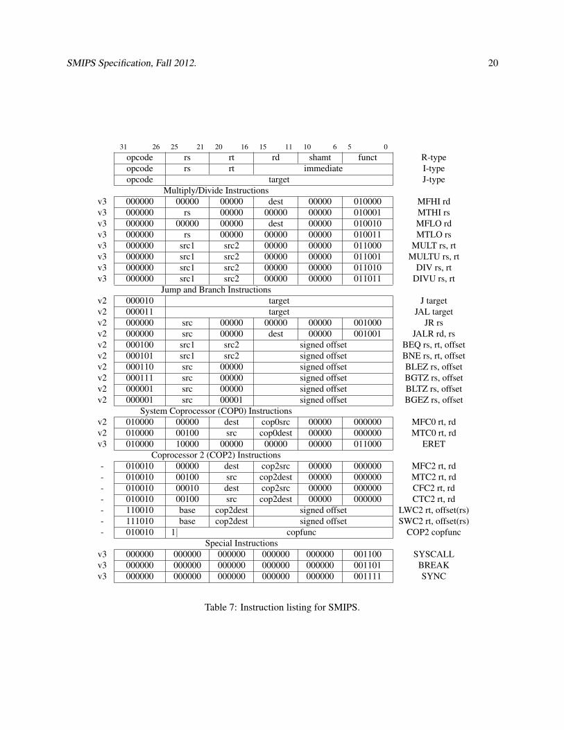
31 26 25 21 20 16 15 11 10 6 5 0opcode rs rt rd shamt funct R-typeopcode rs rt immediate I-typeopcode target J-type
Multiply/Divide Instructionsv3 000000 00000 00000 dest 00000 010000 MFHI rdv3 000000 rs 00000 00000 00000 010001 MTHI rsv3 000000 00000 00000 dest 00000 010010 MFLO rdv3 000000 rs 00000 00000 00000 010011 MTLO rsv3 000000 src1 src2 00000 00000 011000 MULT rs, rtv3 000000 src1 src2 00000 00000 011001 MULTU rs, rtv3 000000 src1 src2 00000 00000 011010 DIV rs, rtv3 000000 src1 src2 00000 00000 011011 DIVU rs, rt
Jump and Branch Instructionsv2 000010 target J targetv2 000011 target JAL targetv2 000000 src 00000 00000 00000 001000 JR rsv2 000000 src 00000 dest 00000 001001 JALR rd, rsv2 000100 src1 src2 signed offset BEQ rs, rt, offsetv2 000101 src1 src2 signed offset BNE rs, rt, offsetv2 000110 src 00000 signed offset BLEZ rs, offsetv2 000111 src 00000 signed offset BGTZ rs, offsetv2 000001 src 00000 signed offset BLTZ rs, offsetv2 000001 src 00001 signed offset BGEZ rs, offset
System Coprocessor (COP0) Instructionsv2 010000 00000 dest cop0src 00000 000000 MFC0 rt, rdv2 010000 00100 src cop0dest 00000 000000 MTC0 rt, rdv3 010000 10000 00000 00000 00000 011000 ERET
Coprocessor 2 (COP2) Instructions- 010010 00000 dest cop2src 00000 000000 MFC2 rt, rd- 010010 00100 src cop2dest 00000 000000 MTC2 rt, rd- 010010 00010 dest cop2src 00000 000000 CFC2 rt, rd- 010010 00100 src cop2dest 00000 000000 CTC2 rt, rd- 110010 base cop2dest signed offset LWC2 rt, offset(rs)- 111010 base cop2dest signed offset SWC2 rt, offset(rs)- 010010 1| copfunc COP2 copfunc
Special Instructionsv3 000000 000000 000000 000000 000000 001100 SYSCALLv3 000000 000000 000000 000000 000000 001101 BREAKv3 000000 000000 000000 000000 000000 001111 SYNC
Table 7: Instruction listing for SMIPS.
SMIPS Specification, Fall 2012. 21
References
[1] J. L. Hennessy and D. A. Patterson. Computer Organization and Design: The Hardware/SoftwareInterface. Morgan Kaufmann, second edition, February 1997. ISBN 1558604286.
[2] MIPS Technologies Inc. MIPS32 architecture for programmers, 2002.http://www.mips.com/publications/processor_architecture.html
[3] G. Kane and J. Heinrich. MIPS RISC Architecture. Prentice Hall, 2nd edition, September 1991. ISBN0135904722.
[4] D. Sweetman. See MIPS Run. Morgan Kaufmann, April 1999. ISBN 1558604103.