Embed Size (px)
Citation preview
SMD Terminal BlocksSmall is Big
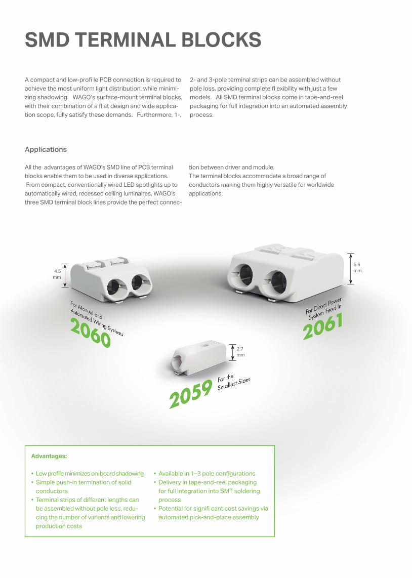
SMD TERMINAL BLOCKSA compact and low-profi le PCB connection is required to achieve the most uniform light distribution, while minimi-zing shadowing. WAGO‘s surface-mount terminal blocks, with their combination of a fl at design and wide applica-tion scope, fully satisfy these demands. Furthermore, 1-,
2- and 3-pole terminal strips can be assembled without pole loss, providing complete fl exibility with just a few models. All SMD terminal blocks come in tape-and-reel packaging for full integration into an automated assembly process.
Applications
All the advantages of WAGO‘s SMD line of PCB terminal blocks enable them to be used in diverse applications. From compact, conventionally wired LED spotlights up to automatically wired, recessed ceiling luminaires, WAGO‘s three SMD terminal block lines provide the perfect connec-
4.5 mm
2.7mm
5.6 mm
Advantages:
• Low profi le minimizes on-board shadowing• Simple push-in termination of solid
conductors• Terminal strips of diff erent lengths can
be assembled without pole loss, redu-cing the number of variants and lowering production costs
• Available in 1–3 pole confi gurations• Delivery in tape-and-reel packaging
for full integration into SMT soldering process
• Potential for signifi cant cost savings via automated pick-and-place assembly
tion between driver and module. The terminal blocks accommodate a broad range of conductors making them highly versatile for worldwide applications.
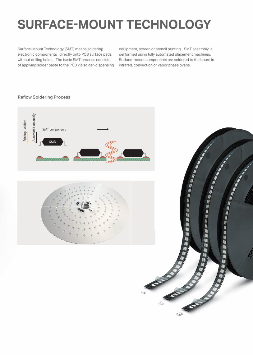
SURFACE�MOUNT TECHNOLOGY Surface-Mount Technology (SMT) means soldering electronic components directly onto PCB surface pads without drilling holes. The basic SMT process consists of applying solder paste to the PCB via solder-dispensing
Reflow Soldering Process
equipment, screen or stencil printing. SMT assembly is performed using fully automated placement machines. Surface-mount components are soldered to the board in infrared, convection or vapor phase ovens.
Auto
mat
ed a
ssem
bly
Prin
ting
(sol
der)
SMT components
SMD
<__ __><__ __>
<_ _>
<> ( )
<_ _>
3
L7.47.9
6.5
2.7
1
2.58.7
0.4
0.5
0.8 0.75
1.4 3
0.3
<_>
<<___ ___>
<___>
<___
><
___
>
<>
()
><__>
(__>
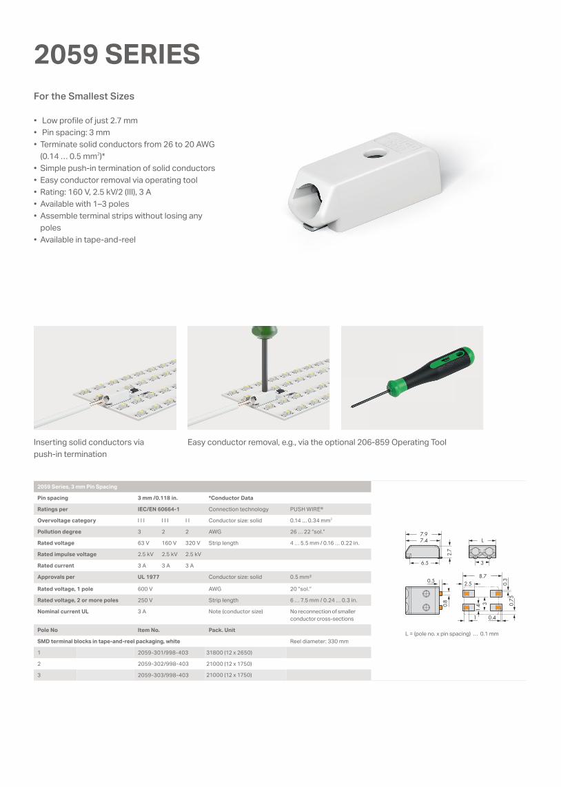
2059 SERIES
• Low profi le of just 2.7 mm• Pin spacing: 3 mm• Terminate solid conductors from 26 to 20 AWG
(0.14 … 0.5 mm2)*• Simple push-in termination of solid conductors• Easy conductor removal via operating tool• Rating: 160 V, 2.5 kV/2 (III), 3 A• Available with 1–3 poles• Assemble terminal strips without losing any
poles• Available in tape-and-reel
Inserting solid conductors via push-in termination
Easy conductor removal, e.g., via the optional 206-859 Operating Tool
For the Smallest Sizes
2059 Series, 3 mm Pin Spacing
Pin spacing 3 mm /0.118 in. *Conductor Data
Ratings per IEC/EN 60664-1 Connection technology PUSH WIRE®
Overvoltage category I I I I I I I I Conductor size: solid 0.14 … 0.34 mm2
Pollution degree 3 2 2 AWG 26 … 22 “sol.”
Rated voltage 63 V 160 V 320 V Strip length 4 … 5.5 mm / 0.16 … 0.22 in.
Rated impulse voltage 2.5 kV 2.5 kV 2.5 kV
Rated current 3 A 3 A 3 A
Approvals per UL 1977 Conductor size: solid 0.5 mm²
Rated voltage, 1 pole 600 V AWG 20 “sol.“
Rated voltage, 2 or more poles 250 V Strip length 6 … 7.5 mm / 0.24 … 0.3 in.
Nominal current UL 3 A Note (conductor size) No reconnection of smaller conductor cross-sections
Pole No Item No. Pack. Unit
SMD terminal blocks in tape-and-reel packaging, white Reel diameter: 330 mm
1 2059-301/998-403 31800 (12 x 2650)
2 2059-302/998-403 21000 (12 x 1750)
3 2059-303/998-403 21000 (12 x 1750)
L = (pole no. x pin spacing) … 0.1 mm
<2.1> 1.
2
2.2
<____
>
L<___ ___>
4< >
<_<6.1 _> 14<__________ _______>
6<_ _> 3.5 <>
4<2 <
>> 0.
4<
___
>
0.4 <___>>0.
95<
___
<__
)
4( )
<_______ _______>12.7<_____ ____>
11.1<____ ____>
4<
>
4.5
<>
13.1
0.4___>
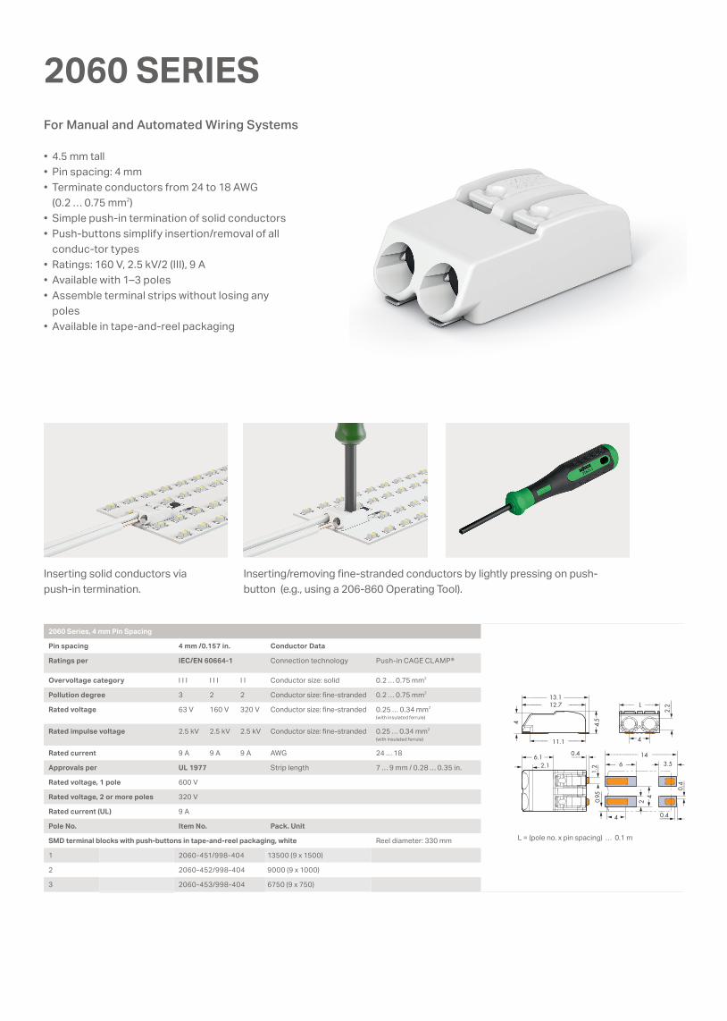
2060 SERIES
• 4.5 mm tall• Pin spacing: 4 mm• Terminate conductors from 24 to 18 AWG
(0.2 … 0.75 mm2)• Simple push-in termination of solid conductors• Push-buttons simplify insertion/removal of all
conduc-tor types• Ratings: 160 V, 2.5 kV/2 (III), 9 A• Available with 1–3 poles• Assemble terminal strips without losing any
poles• Available in tape-and-reel packaging
Inserting solid conductors via push-in termination.
Inserting/removing fi ne-stranded conductors by lightly pressing on push-button (e.g., using a 206-860 Operating Tool).
For Manual and Automated Wiring Systems
2060 Series, 4 mm Pin Spacing
Pin spacing 4 mm /0.157 in. Conductor Data
Ratings per IEC/EN 60664-1 Connection technology Push-in CAGE CLAMP®
Overvoltage category I I I I I I I I Conductor size: solid 0.2 … 0.75 mm2
Pollution degree 3 2 2 Conductor size: fi ne-stranded 0.2 … 0.75 mm2
Rated voltage 63 V 160 V 320 V Conductor size: fi ne-stranded 0.25 … 0.34 mm2
(with insulated ferrule)
Rated impulse voltage 2.5 kV 2.5 kV 2.5 kV Conductor size: fi ne-stranded 0.25 … 0.34 mm2
(with insulated ferrule)
Rated current 9 A 9 A 9 A AWG 24 … 18
Approvals per UL 1977 Strip length 7 … 9 mm / 0.28 … 0.35 in.
Rated voltage, 1 pole 600 V
Rated voltage, 2 or more poles 320 V
Rated current (UL) 9 A
Pole No. Item No. Pack. Unit
SMD terminal blocks with push-buttons in tape-and-reel packaging, white Reel diameter: 330 mm
1 2060-451/998-404 13500 (9 x 1500)
2 2060-452/998-404 9000 (9 x 1000)
3 2060-453/998-404 6750 (9 x 750)
L = (pole no. x pin spacing) … 0.1 mm
L = (pole no. x pin spacing) … 0.1 m

max. 21<_____
<_____________________
______>max. 21<_____ ______>
4.5<
>
> min. 4.4 … max. 6.4
<_____________________> min. 4.4 … max. 6.4
0.4 <___>2.1> 1.
2
<_<6.1 _> 14<__________ _______>
6<_ _> 3.5 <>
<2
>
0.4
<___
>
0.4 <___>>0.
95<
__
2.2
<____
>
11.9<______ ______>
8<___ ___>
4( )
<___
8<
___
___>
>
<_______ _______>12.7<_____ ____>
11.1<____ ____>
4<
>
4.5
<>
13.1
2060 SERIES
The 2-pole SMD terminal block with 8 mm pin spacing has joined WAGO’s portfolio for the higher-rated voltages up to 630 V/6 kV/2 in LED and indust-rial applications.
Besides standard wiring, several LED modules can be easily assembled into a single string using board-to-board con-nection links. This minimizes labor (no manual wiring) and materials needed for connecting LED modules.
WAGO‘s 2060 Series THR PCB Terminal Blocks with soldering pins are ideally suited for THR and wave soldering. The 2060 THR Series is available in both white and black housings. For more in-formation, go to www.wago.com/2060.
Board-to-Board Link8 mm Pin spacing THR and Wave Soldering
2060 Series, Board-to-Board Link
Pin spacing 4 mm / 0.157 in. Pole No. Item No. Pack. Unit
Ratings per IEC/EN 60664-1 1 2060-951/028-000 1500
Overvoltage category I I I I I I I I 2 2060-952/028-000 500
Pollution degree 3 2 2 3 2060-953/028-000 375
Rated voltage 63 V 160 V 320 V
Rated impulse voltage 2.5 kV 2.5 kV 2.5 kV Note: Only suitable for 2060-45x, not for 2060-40x
Rated current 9 A 9 A 9 A
2060 Series, 8 mm Pin Spacing
Pin spacing 8 mm / 0.314 in. Conductor Data
Ratings per IEC/EN 60664-1 Connection technology Push-in CAGE CLAMP®
Overvoltage category I I I I I I I I Conductor size: solid 0.2 … 0.75 mm2
Pollution degree 3 2 2 Conductor size: fi ne-stranded 0.2 … 0.75 mm2
Rated voltage 400 V 630 V 1000 V Conductor size: fi ne-stranded 0.25 … 0.34 mm2
(with insulated ferrule)
Rated impulse voltage 6 kV 6 kV 6 kV Conductor size: fi ne-stranded 0.25 … 0.34 mm2
(with insulated ferrule)
Rated current 9 A 9 A 9 A AWG 24 … 18
Approvals per UL 1977 Strip length 7 … 9 mm / 0.28 … 0.35 in.
Rated voltage 600 V
Rated current (UL) 9 A
Pole No. Item No. Pack. Unit
SMD terminal blocks with push-buttons in tape-and-reel packaging, white Reel diameter: 330 mm
2 2060-852/998-404 6750 (9 x 750)
L = (pole no. x pin spacing) … 0.1 m

>
<_______ _______>15.2<_____ _____>
13.8<____ _____>
0.55 <____>2.2>
5.2
<>
5.6
<>
15.8
3.2
<____
>
L<___ ___>
6< >
<_<6.5 _> 17<_________ _________>
6.5<_ _> 4.5 <>
6<2.
1<
> 0.4
<___
>
2.7 <_>
)<
<
<2.
4
1.8
<> 4.6
>
1.6
• 5.6 mm tall• Pin spacing: 6 mm• Terminate conductors from 20 to 16 AWG
(0.5 … 1.5 mm2)• Simple push-in termination of solid conductors• Push-buttons simplify insertion/removal of all con-
ductor types• Ideal for automated wiring systems• Rating: 320 V, 4 kV/2 (III), 17.5 A• 300 V UL 1059• Available with 1–3 poles• Assemble terminal strips without losing any poles• Available in tape-and-reel packagin
2061 SERIES
Inserting/removing fi ne-stranded conductors by lightly depressing the push-button (e.g., using the optional 206-861 Operating Tool).
The 2061 THR Series is available in both white and black housings.
For Direct Power System Feed-In
2061 Series, 6 mm Pin Spacing
Pin spacing 6 mm / 0.24 in. Conductor Data
Ratings per IEC/EN 60664-1 Connection technology Push-in CAGE CLAMP®
Overvoltage category I I I I I I I I Conductor size: solid 0.5 … 1.5 mm2
Pollution degree 3 2 2 Conductor size: fi ne-stranded 0.5 … 1.5 mm2
Rated voltage 250 V 320 V 630 V Conductor size: fi ne-stranded 0.5 … 0.75 mm2
(with insulated ferrule)
Rated impulse voltage 4 kV 4 kV 4 kV Conductor size: fi ne-stranded 0.5 … 0.75 mm2 (with insulated ferrule)
Rated current 17.5 A 17.5 A 17.5 A AWG 20 … 16
Ratings per UL 1059 Strip length 7 … 10 mm / 0.28 … 0.39 in.
Rated voltage, 1 pole 600 V
Rated voltage, 2 or more poles 300 V
Rated current (UL) 10 A
Pole No. Item No. Pack. Unit
SMD terminal blocks with push-buttons in tape-and-reel packaging, white Reel diameter: 330 mm
1 2061-601/998-404 8100 (9 x 900)
2 2061-602/998-404 6300 (9 x 700)
3 2061-603/998-404 4050 (9 x 450)
L = (pole no. x pin spacing) … 0.3 mm
0888
-015
8/01
02-6
901
– SM
D F
AMIL
Y BR
OC
HUR
E 1.
2 US
– 0
2/20
16-0
0 –
Prin
ted
in G
erm
any
– Su
bjec
t to
desi
gn c
hang
es
WAGO Kontakttechnik GmbH & Co. KGPostfach 2880 · 32385 MindenHansastraße 27 · 32423 [email protected]
Headquarters +49 571/ 887 - 0Sales +49 571/ 887 - 222Order Service +49 571/ 887 - 44333Fax +49 571/ 887 - 844 169
WAGO is a registered trademark of WAGO Verwaltungsgesellschaft mbH. ”Copyright – WAGO Kontakttechnik GmbH & Co. KG – all rights reserved. The content and structure of the WAGO websites, catalogs, videos, and other WAGO media are subject to copyright. Distribution or modification to the contents of these pages and videos is prohibited. Furthermore, the content may neither be copied nor made available to third parties for commercial purposes. Also subject to copyright are the images and videos that were made available to WAGO Kontakttechnik GmbH & Co. KG by third parties.”