Embed Size (px)
DESCRIPTION
Deck Sheet
Citation preview

Metal Decking SpecialistsDesign. Manufacture. Installation.Technical Manual and Guidance Notes

02
ContentsIntroduction03 Introduction
04 Advantages of Metal Decking
05 Our Products and Benefits
Software06 SMD Design Software and Download Details
Design Notes07 Design Table Notes
R5108 R51 Details and Sectional Properties
09 R51 Load Span Tables
10 R51 Fire Tables (TAB-DeckTM Fibres)
TR60+11 TR60+ Details and Sectional Properties
12 TR60+ Load Span Tables S350
13 TR60+ Fire Tables (TAB-DeckTM Fibres)
TR80+14 TR80+ Details and Sectional Properties
15 TR80+ Load Span Tables S350
16 TR80+ Fire Tables (TAB-DeckTM Fibres)
SR6017 SR60 Roof Deck Details and Sectional Properties
17 SR60 Roof Deck Load/Span Tables
Guidance Notes18 Contents
19 Design
22 Supply
23 Installation
26 Studwelding
28 Health and Safety
29 Guidance for Following Trades
30 Concrete – The Complete Package
31 TAB-DeckTM Fibre Concrete
32 Service Fixings
33 Further Reading
33 Other Typical Details
35 Typical Drawing Layout

03
Structural Metal Decks have been in the metal decking industry for over 20 years and have been involved in the development of standard details and best practice methods for the design, supply and installation of composite metal decking and associated works.
This Technical Manual has been developed to assist all parties involved
in the successful design & construction of composite floor slabs using
metal decking.
The manual contains design tables covering the construction,
composite and fire conditions for our entire product range, from our
re-entrant R51 profile to the trapezoidal TR80+ profile. Also included is
the fibre concrete ‘TAB-Deck™’ solution, available exclusively to SMD
decking products in association with our fibre partner, ArcelorMittal
Wire Solutions.
An extensive guidance notes section has been produced with the
customer in mind, to provide guidance on design details and the
methods of best practice for construction.
In addition to the guidance outlined in this document, we would refer
you to the items of ‘further reading’ detailed on page 33 of this manual.
Introduction
Introduction
Ludgate - London

04
Benefits of Using Composite Metal Decking
• Rapid speed of construction, reducing overall project time
• Provides tensile reinforcement in the slab
• Composite construction reduces steelwork frame weight
• Reduced foundation costs, due to reduced loading
• Integral ceiling and service fixing system
• The decking acts as permanent shuttering
• Provides protection for following trades
• When fixed the decking provides a safe working platform
• Minimal site storage requirements
• Easily installed into complex designs, with minimal wastage
• Can achieve up to 4hr fire rating for the slab with exposed soffit
One New Change - London
For project examples visit the gallery section of our website at www.smdltd.co.uk
Advantages of Metal Decking

05
• 51mm deep re-entrant profile• 101mm minimum slab depth, whilst still achieving 1 hour fire rating• Wide flat trough provides flexibility for shear stud positioning• With minimal voids in the concrete section this allows dense slabs to be constructed providing excellent load carrying capacity and good sound insulation• Soffit ‘Wedge Nut’ fixings available with load capacity of up to 2kN• Narrow re-entrant ribs provide virtually flat soffit• Acoustic Robust Solution – Refer ‘Robust Standard Details’• TAB-Deck™ fibre concrete solution now available
• 60mm deep trapezoidal profile• Reduced concrete volume• Enhanced speed of installation due to the 1.0m cover width• Trough stiffeners positioned to ensure central stud position, reducing amount of site checking required• The steel cross sectional area of this profile makes it the most economical option of the three available profiles• Soffit ‘Wedge Nut’ fixings available with load capacity of up to 1kN• Acoustic Robust Solution – Refer ‘Robust Standard Details’• TAB-Deck™ fibre concrete solution now available
• 80mm deep trapezoidal profile• Reduced concrete volume when compared to other decks available on the market• 140mm slab depth required to achieve a typical 1 hour fire rating• Excellent un-propped span capability• Trough stiffeners positioned to ensure central stud position, reducing amount of site checking required• Soffit ‘Wedge Nut’ fixings available with load capacity of up to 1kN• Acoustic Robust Solution – Refer ‘Robust Standard Details’• TAB-Deck™ fibre concrete solution now available
• 60mm deep trapezoidal profile• Optimised design for use in lightweight roof construction, this profile cannot be used as part of a composite slab• Enhanced speed of installation due to the 1.0m cover width• 333mm trough spacing offers an economical solution for our clients• Good spanning capabilities
Our Products and Benefits
Benefits
Benefits
Benefits
Roof Decking Benefits

06 07
Contact us now to receive your copy on +44 (0) 1202 718898 or download our library of technical details from www.smdltd.co.uk
Working together with the SCI, SMD maintain the ‘SMD Deck’
design software to ensure designs are in line with latest code
changes and technical developments. Whilst giving the ability to
carry out complex composite slab calculations, the software also
features intuitive user interfaces, demonstrable quality assurances
and integration with current technical excellence via links to related
SCI publications.
In addition to this, the new software’s ‘automatic update’ feature
gives the user added confidence by ensuring the software is in line
with the latest version.
SMD also has an extensive on-going programme of research and
development, to guarantee our products remain market leaders in
our field.
SMD's experienced technical department is available to address your technical questions and prepare detailed calculations where required.
Our in-house detailing department of qualified designers / detailers utilise the latest AutoCAD and Tekla Structures Building Information Modelling (BIM) software solutions to provide an efficient design service for our clients.
and Download DetailsDesign Software20
10
SMD Deck Version 6.0Composite Metal Decking Design Software
Design SoftwareDesign. Manufacture. Installation.

06 07
The load/span tables detailed in the following pages provide a quick reference
guide for architects, engineers and specifiers. For ease of use, these tables
only cover the more common criteria. More detailed designs should be
checked using the SMD Deck design software.
The notes below detail the design parameters used in the preparation of the
load/span tables contained in this document:
SpansSpans shown in the tables are to centres of supports, based on 100mm
minimum support widths (maximum clear span = value from table - 100mm).
Propped spans assume a 100mm prop width, with props located at mid-span.
Spans can be considered as double span providing adjacent spans differ by no
more than 15%.
DeflectionIn accordance with BS5950 Part 4 and UK NAD to Eurocode 4, construction
stage deflection is limited to the lesser of Span/180 or 20mm when deflection
is less than slab depth/10. This limit is increased to the lesser of Span/130 or
30mm, when concrete ponding is considered for deflections greater than slab
depth/10. The tables in this Technical Manual do not include for any additional
concrete as a result of deflection of the steel frame.
Construction Stage LoadingIn addition to the wet weight of concrete and reinforcement for the specified
slab depth, the following load/span tables allow for a temporary construction
imposed load of 1.5kN/m² in accordance with BS5950 Part 4. Tabulated values
for slab self-weight are for concrete only, they do not include the weight of deck
or reinforcement.
Composite / Fire Stage LoadingThe applied loads indicated in the load/span tables are unfactored and should
include consideration for partitions, ceiling, services and finishes etc. These
should not include the slab self-weight, as this has been included (where
necessary) in the preparation of these tables.
When determining design loadings, consideration should be given to any
loadings that may be applied to the slab during construction (i.e. from plant or
material storage), as these may be more onerous than the design loadings for
the intended building use. In all cases slabs are designed as simply supported,
and in accordance with BS5950 Part 4.
ConcreteAll design tables assume a typical C25/30 concrete grade, with 20mm
aggregate size. The densities used in the preparation of these tables,
in accordance with BS5950 Part 4, are as follows:
• Normal Weight: 2400kg/m³ (Wet) and 2350kg/m³ (Dry).
• Lightweight: 1900kg/m³ (Wet) and 1800kg/m³ (Dry).
Concrete volumes indicated on the sectional properties pages for each profile
are based on the slab being poured to a constant thickness throughout, it is
recommended that an additional volume of span/250 m³/m² be added
to these values to account for additional concrete as a result of deflection of
the decking.
ReinforcementBS 5950 Part 4 specifies mesh sizes as at least 0.1% of the gross concrete
section. Eurocode 4 differs, as BS EN 1994-1-1 specifies 0.2% of the
concrete above the ribs (or 0.4% for propped construction). These tables
meet the more onerous requirements of BS EN 1994-1-1. Lower mesh sizes
to suit BS 5950 may be used – refer to SMD Deck design software.
The top cover to the mesh reinforcement should be a minimum of 15mm
and a maximum of 45mm. Minimum laps should be 300mm for A142 and
400 mm for A193, A252 and A393. The mesh must satisfy the elongation
requirements of BS4449.
FireThe fire resistances indicated in load/span tables use the Simplified 'Mesh
Only' Method with the composite slab and mesh reinforcement (not
necessarily the metal deck) continuous over one or more internal supports.
Continuity is taken to include all end bay conditions.
A Fire imposed load factor of 1.0 is incorporated in these tables, this may
be further reduced for certain applications (i.e. offices where load can be
considered as non-permanent during fire – refer BS 5950 Part 8).
For spans outside the scope of these tables download SMD Deck design
software from www.smdltd.co.uk or consult SCI Publication P-056
(2nd Edition).
Design Table Limits – CriteriaTypically, spans are governed by the maximum 'un-propped' condition at
Construction Stage, except where values are for propped spans and/or are
indicated as follows:
Spans shown in red indicate where spans are limited by the fire condition,
greater spans may be achievable by either increasing mesh size or the
addition of bottom reinforcement – refer SMD Deck Design Software or
contact SMD Technical Department.
Spans shown in blue indicate where spans are limited by the composite/
normal stage condition, greater spans my be achievable where shear studs
are provided, refer SMD Deck Design Software or contact SMD Technical
Department.
Situations not covered by load/span tablesFor situations not covered by SMD load/span tables (i.e. isolated single
span slabs or slabs subjected to concentrated point or line loads), refer
to SMD Deck design software developed in conjunction with The Steel
Construction Institute.
More comprehansive tables are available on our website at www.smdltd.co.uk
Design Table Notes

Details and Sectional PropertiesR51 is manufactured from S350 grade steel. This profile is a traditional re-entrant profile and is commonly used on inner city multi-storey projects where the structural zone and storey height is reduced, due to the relatively thin slab depth required to achieve a typical 1 hour fire rating.
Typical Section Detail
• 51mm deep re-entrant profile
• 101mm minimum slab depth, whilst still achieving 1 hour fire rating
• Wide flat trough provides flexibility for shear stud positioning
• With minimal voids in the concrete section this allows dense slabs to be constructed providing excellent load carrying capacity and good sound insulation
• Soffit ‘Wedge Nut’ fixings available with load capacity of up to 2kN
• Narrow re-entrant ribs provide virtually flat soffit
• Acoustic Robust Solution – Refer ‘Robust Standard Details’
• TAB-Deck™ fibre concrete solution now available
Concrete Volume and Weight
Slab Depth
Volume of Concrete Weight of Concrete (Normal Weight) Weight of Concrete (Lightweight)
mm m³/m² Wet (kN/m²) Dry (kN/m²) Wet (kN/m²) Dry (kN/m²)
120 0.111 2.61 2.56 2.07 1.96
130 0.121 2.85 2.79 2.26 2.14
140 0.131 3.08 3.02 2.44 2.31
150 0.141 3.32 3.25 2.63 2.49
175 0.166 3.91 3.83 3.09 2.93
200 0.191 4.50 4.40 3.56 3.37
225 0.216 5.09 4.98 4.03 3.81
250 0.241 5.67 5.56 4.49 4.26
08 09
Deck Profile
Benefits
Sectional Properties
Nominal thickness mm
Design Thickness (bare steel) mm
Available Grade N/mm2
Depth of Profile mm
Weight of Profile kg/m2 kN/m2
Height of neutral axix mm
Area of Steelmm2/m
Moment of Inertia cm4/m
0.9 0.86 S350 51 12.98 0.128 16.9 1580 62.3
1.0 0.96 S350 51 14.42 0.142 16.9 1764 71.0
1.2 1.16 S350 51 17.30 0.170 16.8 2131 87.7
Deflection – This table is based on concrete poured to a constant thickness and does not take account for deflection of the decking or supporting beams (as a guide, to account for the deflection of the decking a concrete volume of span/250 should be added to the figures indicated). Concrete Weight – These tables indicate concrete weight only and do not include the weight of decking or reinforcement. Concrete weights are based on the concrete densities specified in BS5950 Part 4 clause 3.3.3 as follows: Normal Weight Concrete – 2400kg/m³ (wet) and 2350 kg/m³ (dry). Lightweight Concrete – 1900kg/m³ (wet) and 1800 kg/m³ (dry).
08 09
Maximum Permissible Span (m)
0.9mm Gauge 1.0mm Gauge 1.2mm Gauge
Span Type Fire Rating(hours)
Slab Depth(mm)
Mesh Total Unfactored Applied Load ( kN/m2 )
3.5 5.0 7.5 10.0 3.5 5.0 7.5 10.0 3.5 5.0 7.5 10.0
Sin
gle
Sp
an
1.0
101 A142 2.76 2.76 2.76 2.76 3.00 3.00 3.00 2.93 3.27 3.27 3.27 3.13
130 A193 2.59 2.59 2.59 2.59 2.76 2.76 2.76 2.76 3.04 3.04 3.04 3.04
150 A252 2.46 2.46 2.46 2.46 2.65 2.65 2.65 2.65 2.90 2.90 2.90 2.90
1.5
110 A142 2.68 2.68 2.68 2.45 2.92 2.92 2.92 2.51 3.19 3.19 3.07 2.65
130 A193 2.59 2.59 2.59 2.59 2.76 2.76 2.76 2.76 3.04 3.04 3.04 3.04
150 A252 2.46 2.46 2.46 2.46 2.65 2.65 2.65 2.65 2.90 2.90 2.90 2.90
2.0
125 A193 2.60 2.60 2.60 2.32 2.80 2.80 2.70 2.35 3.08 3.08 2.74 2.41
150 A252 2.46 2.46 2.46 2.46 2.65 2.65 2.65 2.65 2.90 2.90 2.90 2.90
175 A252 2.32 2.32 2.32 2.32 2.52 2.52 2.52 2.52 2.75 2.75 2.75 2.75
Do
uble
Sp
an
1.0
101 A142 3.23 3.23 3.03 2.67 3.47 3.47 3.13 2.76 3.78 3.78 3.32 2.93
130 A193 3.05 3.05 3.05 3.05 3.30 3.30 3.30 3.30 3.51 3.51 3.51 3.51
150 A252 2.89 2.89 2.89 2.89 3.14 3.14 3.14 3.14 3.44 3.44 3.44 3.44
1.5
110 A142 3.22 3.13 2.67 2.38 3.39 3.22 2.75 2.44 3.69 3.38 2.89 2.57
130 A193 3.05 3.05 3.05 2.74 3.30 3.30 3.17 2.81 3.51 3.51 3.32 2.94
150 A252 2.89 2.89 2.89 2.89 3.14 3.14 3.14 3.14 3.44 3.44 3.44 3.35
2.0
125 A193 3.09 2.94 2.52 2.25 3.33 2.98 2.56 2.29 3.45 3.05 2.63 2.35
150 A252 2.89 2.89 2.89 2.65 3.14 3.14 3.01 2.68 3.44 3.44 3.07 2.74
175 A252 2.72 2.72 2.72 2.72 2.98 2.98 2.98 2.84 3.26 3.26 3.26 2.91
Do
uble
Sp
an (P
rop
ped
)
1.0
101 A252 4.13 3.70 3.21 2.88 4.24 3.80 3.30 2.96 4.45 3.99 3.46 3.11
130 A393 4.86 4.34 3.76 3.36 4.98 4.52 3.97 3.55 5.19 4.71 4.14 3.74
150 2 x A252 5.10 4.59 4.00 3.59 5.38 4.84 4.22 3.79 5.66 5.18 4.58 4.15
1.5
110 A252 3.76 3.38 2.94 2.64 3.84 3.45 3.01 2.70 4.00 3.59 3.13 2.81
130 A393 4.39 3.97 3.49 3.15 4.47 4.05 3.55 3.21 4.62 4.18 3.67 3.32
150 2 x A252 4.84 4.42 3.91 3.54 4.92 4.49 3.97 3.60 5.08 4.63 4.10 3.71
2.0
125 A393 3.85 3.48 3.05 2.75 3.89 3.52 3.08 2.78 3.97 3.59 3.14 2.84
150 2 x A252 4.35 3.96 3.50 3.17 4.39 4.00 3.53 3.20 4.46 4.07 3.60 3.26
175 2 x A252 4.49 4.12 3.67 3.34 4.54 4.17 3.71 3.38 4.62 4.24 3.78 3.44
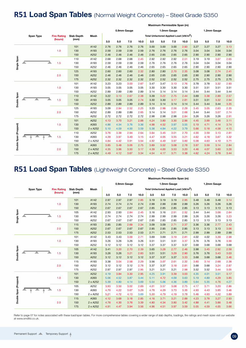
Load Span Tables (Normal Weight Concrete) – Steel Grade S350
Load Span Tables (Lightweight Concrete) – Steel Grade S350
Maximum Permissible Span (m)
0.9mm Gauge 1.0mm Gauge 1.2mm Gauge
Span Type Fire Rating(hours)
Slab Depth(mm)
Mesh Total Unfactored Applied Load ( kN/m2 )
3.5 5.0 7.5 10.0 3.5 5.0 7.5 10.0 3.5 5.0 7.5 10.0
Sin
gle
Sp
an
1.0
101 A142 2.97 2.97 2.97 2.85 3.19 3.19 3.19 2.95 3.48 3.48 3.48 3.14
130 A193 2.74 2.74 2.74 2.74 2.99 2.99 2.99 2.99 3.26 3.26 3.26 3.26
150 A252 2.67 2.67 2.67 2.67 2.85 2.85 2.85 2.85 3.13 3.13 3.13 3.13
1.5
105 A142 2.93 2.93 2.84 2.45 3.16 3.16 2.91 2.52 3.44 3.44 3.06 2.64
130 A193 2.74 2.74 2.74 2.74 2.99 2.99 2.99 2.99 3.26 3.26 3.26 3.23
150 A252 2.67 2.67 2.67 2.67 2.85 2.85 2.85 2.85 3.13 3.13 3.13 3.13
2.0
115 A193 2.85 2.85 2.69 2.34 3.09 3.09 2.71 2.37 3.36 3.36 2.77 2.43
150 A252 2.67 2.67 2.67 2.67 2.85 2.85 2.85 2.85 3.13 3.13 3.13 3.06
175 A252 2.53 2.53 2.53 2.53 2.71 2.71 2.71 2.71 2.99 2.99 2.99 2.99
Do
uble
Sp
an
1.0
101 A142 3.43 3.43 3.09 2.71 3.69 3.69 3.19 2.81 4.02 4.02 3.39 2.98
130 A193 3.26 3.26 3.26 3.26 3.51 3.51 3.51 3.37 3.76 3.76 3.76 3.56
150 A252 3.12 3.12 3.12 3.12 3.37 3.37 3.37 3.37 3.68 3.68 3.68 3.68
1.5
105 A142 3.41 3.20 2.70 2.39 3.65 3.28 2.77 2.46 3.98 3.45 2.92 2.58
130 A193 3.26 3.26 3.21 2.83 3.51 3.51 3.29 2.90 3.76 3.76 3.43 3.03
150 A252 3.12 3.12 3.12 3.12 3.37 3.37 3.37 3.33 3.68 3.68 3.68 3.46
2.0
115 A193 3.38 3.04 2.58 2.29 3.56 3.07 2.61 2.32 3.60 3.14 2.68 2.38
150 A252 3.12 3.12 3.12 2.78 3.37 3.37 3.18 2.81 3.68 3.68 3.24 2.87
175 A252 2.97 2.97 2.97 2.95 3.21 3.21 3.21 2.98 3.52 3.52 3.44 3.05
Do
uble
Sp
an (P
rop
ped
)
1.0
101 A252 4.19 3.84 3.30 2.95 4.25 3.91 3.39 3.03 4.35 4.01 3.51 3.17
130 A393 5.06 4.52 3.87 3.44 5.11 4.72 4.09 3.63 5.19 4.89 4.29 3.85
150 2 x A252 5.39 4.80 4.14 3.69 5.54 5.06 4.36 3.89 5.64 5.35 4.76 4.27
1.5
105 A252 3.93 3.50 3.02 2.69 4.01 3.57 3.08 2.75 4.17 3.71 3.20 2.86
130 A393 4.70 4.22 3.67 3.29 4.78 4.29 3.73 3.35 4.93 4.43 3.85 3.46
150 2 x A252 5.21 4.72 4.13 3.69 5.30 4.79 4.19 3.78 5.46 4.93 4.32 3.89
2.0
115 A393 4.12 3.68 3.18 2.85 4.16 3.71 3.21 2.88 4.23 3.78 3.27 2.93
150 2 x A252 4.76 4.30 3.76 3.39 4.80 4.34 3.80 3.42 4.88 4.41 3.86 3.48
175 2 x A252 4.91 4.47 3.94 3.56 4.96 4.51 3.97 3.59 5.05 4.59 4.05 3.66
Refer to page 07 for notes associated with these load/span tables. For more comprehensive tables covering a wider range of slab depths, loadings, fire ratings and mesh sizes visit our website at www.smdltd.co.uk.
Permanent Support Temporary Support

10 11
Minimum Insulation Thickness (x) of Concrete (mm)
Fire Rating 1 hr 1.5 hr 2 hr 3 hr 4 hr
NWC 90 110 125 150 170
LWC 90 105 115 135 150
The image and table above details the minimum insulation thickness required to suit fire design criteria – in accordance with BS5950 Part 8.
R51 Fire Tables – TAB-DeckTM Fibres
R51 Fire Insulation Thickness
Maximum Permissible Span (m)
0.9mm Gauge 1.0mm Gauge 1.2mm Gauge
Span Type Fire Rating(hours)
Slab Depth(mm)
Steel Fibre Total Unfactored Applied Load ( kN/m2 )
3.5 5.0 7.5 10.0 3.5 5.0 7.5 10.0 3.5 5.0 7.5 10.0
Do
uble
Sp
an
1.0
101 HE 1.0/50 3.23 3.23 3.23 3.18 3.47 3.47 3.47 3.34 3.78 3.78 3.78 3.46
130 HE 1.0/50 3.05 3.05 3.05 3.05 3.30 3.30 3.30 3.30 3.51 3.51 3.51 3.51
150 HE 1.0/50 2.89 2.89 2.89 2.89 3.14 3.14 3.14 3.14 3.44 3.44 3.44 3.44
1.5
110 HE 1.0/50 3.22 3.21 2.82 2.54 3.39 3.34 2.93 2.64 3.69 3.58 3.14 2.83
130 HE 1.0/50 3.05 3.05 3.05 2.79 3.30 3.30 3.19 2.89 3.51 3.51 3.42 3.10
150 HE 1.0/50 2.89 2.89 2.89 2.89 3.14 3.14 3.14 3.14 3.44 3.44 3.44 3.35
2.0
125 HE 1.0/50 3.09 2.95 2.60 2.35 3.33 3.07 2.70 2.44 3.45 3.27 2.88 2.61
150 HE 1.0/50 2.89 2.89 2.89 2.71 3.14 3.14 3.09 2.81 3.44 3.44 3.28 2.98
175 HE 1.0/50 2.72 2.72 2.72 2.72 2.98 2.98 2.98 2.98 3.26 3.26 3.26 3.19
Permanent Support Temporary Support
Maximum Permissible Span (m)
0.9mm Gauge 1.0mm Gauge 1.2mm Gauge
Span Type Fire Rating(hours)
Slab Depth(mm)
Steel Fibre Total Unfactored Applied Load ( kN/m2 )
3.5 5.0 7.5 10.0 3.5 5.0 7.5 10.0 3.5 5.0 7.5 10.0
Do
uble
Sp
an
1.0
101 HE 1.0/50 3.43 3.43 3.39 3.08 3.69 3.69 3.44 3.12 4.02 4.02 3.53 3.21
130 HE 1.0/50 3.26 3.26 3.26 3.26 3.51 3.51 3.51 3.51 3.76 3.76 3.76 3.76
150 HE 1.0/50 3.12 3.12 3.12 3.12 3.37 3.37 3.37 3.37 3.68 3.68 3.68 3.68
1.5
105 HE 1.0/50 3.41 3.19 2.76 2.47 3.65 3.32 2.87 2.57 3.98 3.57 3.09 2.77
130 HE 1.0/50 3.26 3.26 3.23 2.91 3.51 3.51 3.34 3.01 3.76 3.76 3.56 3.21
150 HE 1.0/50 3.12 3.12 3.12 3.12 3.37 3.37 3.37 3.27 3.68 3.68 3.68 3.47
2.0
115 HE 1.0/50 3.33 2.99 2.60 2.33 3.46 3.10 2.70 2.42 3.69 3.31 2.88 2.58
150 HE 1.0/50 3.12 3.12 3.12 2.86 3.37 3.37 3.27 2.96 3.68 3.68 3.45 3.11
175 HE 1.0/50 2.97 2.97 2.97 2.97 3.21 3.21 3.21 3.20 3.52 3.52 3.52 3.35
Normal Weight Concrete
Lightweight Concrete
For further guidance on the design of TAB-DeckTM fibre reinforced slabs, download the TAB-DeckTM design manual at www.smdltd.co.uk

10 11
Details and Sectional PropertiesThe TR60 profile was SMD's first trapezoidal profile, added to our product range in 1992. Further research and development in recent years has seen our trapezoidal products evolve into the TR+ range. The profile enables un-propped spans in excess of 3.5m and is available in 0.9mm, 1.0mm and 1.2mm gauges in both S350 and S450 grade steel.
Sectional Properties
Nominal thickness mm
Design Thickness (bare steel) mm
Available Grades N/mm2
Depth of Profile mm
Weight of Profile kg/m2 kN/m2
Height of neutral axix mm
Area of Steelmm2/m
Moment of Inertia cm4/m
0.9 0.86 S350 or S450 60 / 72* 9.99 0.098 33.6 1216 93.5
1.0 0.96 S350 or S450 60 / 72* 11.08 0.109 33.6 1355 102.1
1.2 1.16 S350 or S450 60 / 72* 13.26 0.130 33.7 1633 119.8
Note: Figures against depth of profile indicate the nominal depth, with overall depth (including height of re-entrant) marked *.
Deck Profile
Concrete Volume and WeightSlab Depth
Volume of Concrete Weight of Concrete (Normal Weight) Weight of Concrete (Lightweight)
mm m³/m² Wet (kN/m²) Dry (kN/m²) Wet (kN/m²) Dry (kN/m²)
120 0.086 2.02 1.98 1.60 1.52
130 0.096 2.26 2.21 1.79 1.70
140 0.106 2.50 2.44 1.98 1.87
150 0.116 2.73 2.67 2.16 2.05
175 0.141 3.32 3.25 2.63 2.49
200 0.166 3.91 3.83 3.09 2.93
225 0.191 4.50 4.40 3.56 3.37
250 0.216 5.09 4.98 4.03 3.81
Typical Section Detail
• 60mm deep trapezoidal profile
• Reduced concrete volume
• Enhanced speed of installation due to the 1.0m cover width
• Trough stiffeners positioned to ensure central stud position, reducing amount of site checking required
• The steel cross sectional area of this profile makes it the most economical option of the three available profiles
• Soffit ‘Wedge Nut’ fixings available with load capacity of up to 1kN
• Acoustic Robust Solution – Refer ‘Robust Standard Details’
• TAB-Deck™ fibre concrete solution now available
Benefits
Deflection – This table is based on concrete poured to a constant thickness and does not take account for deflection of the decking or supporting beams (as a guide, to account for the deflection of the decking a concrete volume of span/250 should be added to the figures indicated). Concrete Weight – These tables indicate concrete weight only and do not include the weight of decking or reinforcement. Concrete weights are based on the concrete densities specified in BS5950 Part 4 clause 3.3.3 as follows: Normal Weight Concrete – 2400kg/m³ (wet) and 2350 kg/m³ (dry). Lightweight Concrete – 1900kg/m³ (wet) and 1800 kg/m³ (dry).
Refer to page 07 for notes associated with these load/span tables. For more comprehensive tables covering a wider range of slab depths, loadings, fire ratings and mesh sizes visit our website at www.smdltd.co.uk.

12 13Permanent Support Temporary Support
Maximum Permissible Span (m)
0.9mm Gauge 1.0mm Gauge 1.2mm Gauge
Span Type Fire Rating(hours)
Slab Depth(mm)
Mesh Total Unfactored Applied Load ( kN/m2 )
3.5 5.0 7.5 10.0 3.5 5.0 7.5 10.0 3.5 5.0 7.5 10.0
Sin
gle
Sp
an
1.0
120 A142 3.44 3.44 3.07 2.67 3.72 3.72 3.14 2.74 4.05 4.05 3.28 2.86
150 A193 3.20 3.20 3.20 3.20 3.47 3.47 3.47 3.47 3.79 3.79 3.79 3.63
200 A393 2.95 2.95 2.95 2.95 3.14 3.14 3.14 3.14 3.44 3.44 3.44 3.44
1.5
130 A193 3.35 3.35 3.26 2.78 3.63 3.63 3.29 2.81 3.97 3.97 3.32 2.88
150 A193 3.20 3.20 3.20 2.99 3.47 3.47 3.47 3.02 3.79 3.79 3.68 3.10
200 A393 2.95 2.95 2.95 2.95 3.14 3.14 3.14 3.14 3.44 3.44 3.44 3.44
2.0
140 A193 3.27 3.27 3.03 2.63 3.55 3.55 3.04 2.65 3.88 3.88 3.07 2.69
175 A252 3.12 3.12 3.12 3.12 3.29 3.29 3.29 3.29 3.60 3.60 3.60 3.43
200 A393 2.95 2.95 2.95 2.95 3.14 3.14 3.14 3.14 3.44 3.44 3.44 3.44
Do
uble
Sp
an
1.0
120 A142 3.94 3.52 2.96 2.62 4.18 3.60 3.03 2.68 4.41 3.75 3.16 2.79
150 A193 3.63 3.63 3.61 3.17 3.97 3.97 3.68 3.24 4.43 4.43 3.82 3.36
200 A393 3.23 3.23 3.23 3.23 3.54 3.54 3.54 3.54 4.10 4.10 4.10 4.10
1.5
130 A193 3.83 3.63 3.05 2.70 4.06 3.68 3.09 2.73 4.44 3.76 3.17 2.81
150 A193 3.63 3.63 3.24 2.87 3.97 3.91 3.29 2.91 4.43 4.00 3.38 2.99
200 A393 3.23 3.23 3.23 3.23 3.54 3.54 3.54 3.54 4.10 4.10 4.10 4.10
2.0
140 A193 3.73 3.42 2.89 2.56 3.97 3.44 2.92 2.58 4.00 3.48 2.96 2.63
175 A252 3.42 3.42 3.42 3.12 3.74 3.74 3.56 3.13 4.19 4.19 3.59 3.17
200 A393 3.23 3.23 3.23 3.23 3.54 3.54 3.54 3.54 4.10 4.10 4.10 4.10
Do
uble
Sp
an (P
rop
ped
) 1.0
120 A252 4.32 3.92 3.37 3.00 4.38 3.99 3.43 3.05 4.48 4.10 3.54 3.15
150 A393 5.09 4.75 4.17 3.74 5.14 4.82 4.23 3.79 5.23 4.93 4.34 3.89
200 2 x A393 4.89 4.89 4.89 4.53 5.39 5.39 5.34 4.69 6.18 5.89 5.52 4.98
1.5
130 A393 4.58 4.23 3.70 3.32 4.64 4.29 3.75 3.35 4.75 4.39 3.81 3.40
150 A393 5.03 4.51 3.91 3.51 5.08 4.55 3.95 3.54 5.17 4.64 4.02 3.61
200 2 x A393 4.89 4.89 4.89 4.53 5.39 5.39 5.06 4.57 6.18 5.81 5.12 4.64
2.0
140 A393 4.62 4.13 3.57 3.19 4.68 4.18 3.61 3.23 4.77 4.26 3.68 3.30
175 2 x A252 5.09 4.59 4.02 3.62 5.12 4.62 4.04 3.64 5.18 4.68 4.09 3.68
200 2 x A393 4.89 4.89 4.83 4.37 5.39 5.39 4.85 4.38 6.07 5.53 4.88 4.42
Maximum Permissible Span (m)
0.9mm Gauge 1.0mm Gauge 1.2mm Gauge
Span Type Fire Rating(hours)
Slab Depth(mm)
Mesh Total Unfactored Applied Load ( kN/m2 )
3.5 5.0 7.5 10.0 3.5 5.0 7.5 10.0 3.5 5.0 7.5 10.0
Sin
gle
Sp
an
1.0
130 A142 3.15 3.15 3.15 2.74 3.40 3.40 3.28 2.81 3.71 3.71 3.43 2.93
150 A193 2.99 2.99 2.99 2.99 3.24 3.24 3.24 3.24 3.53 3.53 3.53 3.53
200 A393 2.71 2.71 2.71 2.71 2.90 2.90 2.90 2.90 3.20 3.20 3.20 3.20
1.5
140 A193 3.06 3.06 3.06 2.76 3.28 3.28 3.28 2.79 3.62 3.62 3.35 2.87
150 A193 2.99 2.99 2.99 2.88 3.24 3.24 3.24 2.91 3.53 3.53 3.53 2.99
200 A393 2.71 2.71 2.71 2.71 2.90 2.90 2.90 2.90 3.20 3.20 3.20 3.20
2.0
150 A193 2.99 2.99 2.91 2.55 3.24 3.24 2.92 2.56 3.53 3.53 2.95 2.60
175 A252 2.89 2.89 2.89 2.89 3.06 3.06 3.06 3.06 3.35 3.35 3.35 3.25
200 A393 2.71 2.71 2.71 2.71 2.90 2.90 2.90 2.90 3.20 3.20 3.20 3.20
Do
uble
Sp
an
1.0
130 A142 3.59 3.53 3.00 2.66 3.83 3.61 3.07 2.73 4.34 3.77 3.21 2.85
150 A193 3.38 3.38 3.38 3.09 3.70 3.70 3.57 3.15 4.12 4.12 3.71 3.28
200 A393 2.97 2.97 2.97 2.97 3.18 3.18 3.18 3.18 3.76 3.76 3.76 3.76
1.5
140 A193 3.48 3.48 2.99 2.66 3.80 3.56 3.03 2.70 4.22 3.66 3.12 2.77
150 A193 3.38 3.38 3.10 2.75 3.70 3.69 3.14 2.79 4.12 3.78 3.23 2.87
200 A393 2.97 2.97 2.97 2.97 3.18 3.18 3.18 3.18 3.76 3.76 3.76 3.76
2.0
150 A193 3.38 3.23 2.77 2.47 3.69 3.25 2.79 2.49 3.73 3.29 2.83 2.53
175 A252 3.16 3.16 3.16 2.94 3.44 3.44 3.33 2.96 3.91 3.91 3.37 2.99
200 A393 2.97 2.97 2.97 2.97 3.18 3.18 3.18 3.12 3.76 3.76 3.55 3.16
Do
uble
Sp
an (P
rop
ped
) 1.0
130 A393 4.78 4.37 3.80 3.24 4.84 4.43 3.85 3.34 4.96 4.54 3.95 3.53
150 A393 5.04 4.56 4.00 3.60 5.12 4.63 4.06 3.66 5.26 4.76 4.17 3.76
200 2 x A393 4.42 4.42 4.42 4.42 4.88 4.88 4.88 4.56 5.70 5.70 5.31 4.79
1.5
140 A393 4.54 4.09 3.57 3.21 4.59 4.13 3.61 3.25 4.67 4.21 3.68 3.31
150 A393 4.65 4.20 3.68 3.32 4.70 4.25 3.72 3.35 4.79 4.33 3.79 3.42
200 2 x A393 4.42 4.42 4.42 4.21 4.88 4.88 4.65 4.24 5.70 5.29 4.72 4.30
2.0
150 A393 4.31 3.89 3.41 3.07 4.33 3.92 3.43 3.09 4.38 3.96 3.47 3.13
175 2 x A252 4.78 4.49 3.97 3.59 4.95 4.52 3.99 3.62 5.00 4.56 4.03 3.65
200 2 x A393 4.42 4.42 4.15 3.78 4.88 4.68 4.17 3.80 5.14 4.72 4.20 3.83
Load Span Tables (Normal Weight Concrete) – Steel Grade S350
Load Span Tables (Lightweight Concrete) – Steel Grade S350

12 13
Minimum Insulation Thickness (x) of Concrete (mm)
Fire Rating 1 hr 1.5 hr 2 hr 3 hr 4 hr
NWC 70 80 90 115 130
LWC 60 70 80 100 115
The image and table above details the minimum insulation thickness required to suit fire design criteria – in accordance with BS5950 Part 8.
Maximum Permissible Span (m)
0.9mm Gauge 1.0mm Gauge 1.2mm Gauge
Span Type Fire Rating(hours)
Slab Depth(mm)
Steel Fibre Total Unfactored Applied Load ( kN/m2 )
3.5 5.0 7.5 10.0 3.5 5.0 7.5 10.0 3.5 5.0 7.5 10.0
Do
uble
Sp
an
1.0
130 HE 1.0/50 3.59 3.42 2.99 2.68 3.83 3.54 3.09 2.78 4.19 3.80 3.33 2.99
150 HE 1.0/50 3.38 3.38 3.30 2.98 3.70 3.70 3.42 3.10 4.12 4.10 3.63 3.28
200 HE 1.0/50 2.99 2.99 2.99 2.99 3.20 3.20 3.20 3.20 3.78 3.78 3.78 3.78
1.5
140 HE 1.0/50 3.21 2.90 2.54 2.12 3.29 2.98 2.61 2.18 3.47 3.14 2.75 2.48
150 HE 1.0/50 3.37 3.06 2.69 2.26 3.46 3.15 2.77 2.50 3.63 3.30 2.90 2.62
200 HE 1.0/50 2.99 2.99 2.99 2.92 3.20 3.20 3.20 3.20 3.78 3.78 3.63 3.32
2.0
150 HE 1.0/50 3.21 2.91 2.56 2.14 3.31 3.01 2.64 2.20 3.46 3.14 2.76 2.32
175 HE 1.0/50 3.17 3.17 2.64 2.40 3.45 3.28 2.71 2.46 3.72 3.42 2.83 2.57
200 HE 1.0/50 2.99 2.99 2.99 2.79 3.20 3.20 3.20 2.85 3.78 3.78 3.48 2.95
Fire Insulation Thickness
Fire Tables – TAB-DeckTM Fibres
Maximum Permissible Span (m)
0.9mm Gauge 1.0mm Gauge 1.2mm Gauge
Span Type Fire Rating(hours)
Slab Depth(mm)
Steel Fibre Total Unfactored Applied Load ( kN/m2 )
3.5 5.0 7.5 10.0 3.5 5.0 7.5 10.0 3.5 5.0 7.5 10.0
Do
uble
Sp
an
1.0
120 HE 1.0/50 3.81 3.39 2.93 2.61 3.95 3.52 3.03 2.71 4.21 3.76 3.24 2.89
150 HE 1.0/50 3.64 3.64 3.39 3.05 3.98 3.98 3.52 3.16 4.43 4.32 3.78 3.40
200 HE 1.0/50 3.25 3.25 3.25 3.25 3.56 3.56 3.56 3.56 4.12 4.12 4.12 4.07
1.5
130 HE 1.0/50 3.25 2.90 2.51 2.24 3.34 2.98 2.58 2.31 3.54 3.16 2.74 2.45
150 HE 1.0/50 3.64 3.31 2.88 2.59 3.76 3.39 2.95 2.65 3.92 3.53 3.08 2.76
200 HE 1.0/50 3.25 3.25 3.25 3.25 3.56 3.56 3.56 3.36 4.12 4.12 3.84 3.49
2.0
140 HE 1.0/50 3.34 2.99 2.59 2.15 3.42 3.07 2.66 2.20 3.58 3.21 2.78 2.49
175 HE 1.0/50 3.43 3.43 3.07 2.57 3.75 3.56 3.13 2.62 4.08 3.71 3.26 2.73
200 HE 1.0/50 3.25 3.25 3.25 3.21 3.56 3.56 3.56 3.26 4.12 4.12 3.71 3.36
Normal Weight Concrete
Lightweight Concrete
For further guidance on the design of TAB-DeckTM fibre reinforced slabs, download the TAB-DeckTM design manual at www.smdltd.co.uk

14 15
Details and Sectional PropertiesInitially added to our product range in 2002, the original TR80 has undergone further research and development, evolving to the now revised profile, renamed . This 80mm deep trapezoidal profile is available in 0.9mm, 1.0mm and 1.2mm gauges in both S350 and S450 grade steel.
Slab Depth
Volume of Concrete Weight of Concrete (Normal Weight) Weight of Concrete (Lightweight)
mm m³/m² Wet (kN/m²) Dry (kN/m²) Wet (kN/m²) Dry (kN/m²)
140 0.096 2.26 2.21 1.79 1.70
150 0.106 2.50 2.44 1.98 1.87
160 0.116 2.73 2.67 2.16 2.05
170 0.126 2.97 2.90 2.35 2.22
180 0.136 3.20 3.14 2.53 2.40
200 0.156 3.67 3.60 2.91 2.75
225 0.181 4.26 4.17 3.37 3.20
250 0.206 4.85 4.75 3.84 3.64
Concrete Volume and Weight Typical Section Detail
• 80mm deep trapezoidal profile
• Reduced concrete volume when compared to other decks available on the market
• 140mm slab depth required to achieve a typical 1 hour fire rating
• Excellent un-propped span capability
• Trough stiffeners positioned to ensure central stud position, minimizing site checking required
• Soffit ‘Wedge Nut’ fixings available with load capacity of up to 1kN
• Acoustic Robust Solution – Refer ‘Robust Standard Details’
• TAB-Deck™ fibre concrete solution now available
Benefits
Note: Figures against depth of profile indicate the nominal depth, with overall depth (including height of re-entrant) marked *.
Deck Profile
Sectional Properties
Nominal thickness mm
Design Thickness (bare steel) mm
Available Grades N/mm2
Depth of Profile mm
Weight of Profile kg/m2 kN/m2
Height of neutral axix mm
Area of Steelmm2/m
Moment of Inertia cm4/m
0.9 0.86 S350 or S450 80 / 92* 11.37 0.112 42.3 1385 172.9
1.0 0.96 S350 or S450 80 / 92* 12.59 0.123 42.4 1539 192.3
1.2 1.16 S350 or S450 80 / 92* 15.10 0.148 42.5 1860 231.1
Deflection – This table is based on concrete poured to a constant thickness and does not take account for deflection of the decking or supporting beams (as a guide, to account for the deflection of the decking a concrete volume of span/250 should be added to the figures indicated). Concrete Weight – These tables indicate concrete weight only and do not include the weight of decking or reinforcement. Concrete weights are based on the concrete densities specified in BS5950 Part 4 clause 3.3.3 as follows: Normal Weight Concrete – 2400kg/m³ (wet) and 2350 kg/m³ (dry). Lightweight Concrete – 1900kg/m³ (wet) and 1800 kg/m³ (dry).
Refer to page 07 for notes associated with these load/span tables. For more comprehensive tables covering a wider range of slab depths, loadings, fire ratings and mesh sizes visit our website at www.smdltd.co.uk.

14 15
Load Span Tables (Lightweight Concrete) – Steel Grade S350
Maximum Permissible Span (m)
0.9mm Gauge 1.0mm Gauge 1.2mm Gauge
Span Type Fire Rating(hours)
Slab Depth(mm)
Mesh Total Unfactored Applied Load ( kN/m2 )
3.5 5.0 7.5 10.0 3.5 5.0 7.5 10.0 3.5 5.0 7.5 10.0
Sin
gle
Sp
an
1.0
140 A193 3.92 3.92 3.47 3.04 4.21 4.21 3.54 3.10 4.39 4.39 3.67 3.22
160 A193 3.73 3.73 3.73 3.28 4.02 4.02 3.92 3.35 4.23 4.23 4.06 3.48
200 A252 3.42 3.42 3.42 3.42 3.69 3.69 3.69 3.69 3.98 3.98 3.98 3.98
1.5
150 A193 3.82 3.78 3.10 2.74 4.12 3.81 3.15 2.78 4.31 3.88 3.23 2.87
175 A193 3.61 3.61 3.42 3.01 3.89 3.89 3.46 3.05 4.13 4.13 3.55 3.14
200 A252 3.42 3.42 3.42 3.42 3.69 3.69 3.69 3.68 3.98 3.98 3.98 3.73
2.0
160 A193 3.73 3.36 2.85 2.53 3.98 3.37 2.87 2.56 3.96 3.41 2.92 2.60
175 A193 3.61 3.61 3.02 2.68 3.89 3.63 3.04 2.71 4.13 3.61 3.09 2.75
200 A252 3.42 3.42 3.42 3.21 3.69 3.69 3.69 3.22 3.98 3.98 3.74 3.24
Do
uble
Sp
an
1.0
140 A193 4.42 3.90 3.33 2.96 4.59 3.98 3.40 3.02 4.70 4.13 3.53 3.14
160 A193 4.18 4.16 3.55 3.17 4.49 4.24 3.63 3.24 5.02 4.41 3.78 3.37
200 A252 3.78 3.78 3.78 3.78 4.12 4.12 4.12 3.85 4.62 4.62 4.48 3.99
1.5
150 A193 3.95 3.50 3.01 2.69 4.00 3.55 3.06 2.73 4.11 3.65 3.15 2.82
175 A193 4.01 3.78 3.26 2.92 4.31 3.83 3.32 2.97 4.42 3.94 3.42 3.07
200 A252 3.77 3.77 3.77 3.37 4.12 4.12 3.82 3.41 4.62 4.54 3.91 3.51
2.0
160 A193 3.60 3.21 2.78 2.49 3.63 3.24 2.81 2.52 3.68 3.30 2.86 2.57
175 A193 3.77 3.37 2.92 2.63 3.79 3.40 2.95 2.65 3.85 3.45 3.01 2.71
200 A252 3.77 3.77 3.41 3.06 4.12 3.97 3.44 3.08 4.48 4.01 3.48 3.13
Do
uble
Sp
an (P
rop
ped
)
1.0
140 A393 5.02 4.49 3.67 3.15 5.09 4.57 3.80 3.27 5.23 4.70 4.05 3.50
160 A393 5.24 4.74 4.04 3.48 5.32 4.81 4.18 3.61 5.47 4.95 4.33 3.86
200 2 x A252 5.42 5.40 4.67 4.05 5.98 5.48 4.82 4.19 6.14 5.63 4.99 4.47
1.5
150 A393 4.64 4.18 3.65 3.28 4.69 4.22 3.69 3.31 4.78 4.31 3.76 3.38
175 A393 4.92 4.47 3.93 3.55 4.97 4.52 3.97 3.59 5.08 4.61 4.06 3.67
200 2 x A252 5.25 4.81 4.26 3.87 5.32 4.87 4.32 3.92 5.54 5.07 4.50 4.09
2.0
160 A393 4.39 3.97 3.47 3.13 4.42 3.99 3.50 3.15 4.47 4.04 3.54 3.19
175 2 x A252 4.58 4.16 3.66 3.31 4.61 4.19 3.69 3.33 4.72 4.29 3.78 3.42
200 2 x A252 4.85 4.43 3.93 3.57 4.88 4.47 3.96 3.60 4.95 4.53 4.02 3.65
Permanent Support Temporary Support
Maximum Permissible Span (m)
0.9mm Gauge 1.0mm Gauge 1.2mm Gauge
Span Type Fire Rating(hours)
Slab Depth(mm)
Mesh Total Unfactored Applied Load ( kN/m2 )
3.5 5.0 7.5 10.0 3.5 5.0 7.5 10.0 3.5 5.0 7.5 10.0
Sin
gle
Sp
an
1.0
140 A193 4.19 4.19 3.58 3.12 4.44 4.44 3.65 3.18 4.64 4.64 3.79 3.31
160 A193 4.00 4.00 3.95 3.36 4.28 4.28 4.01 3.43 4.47 4.47 4.16 3.56
200 A252 3.69 3.69 3.69 3.69 3.99 3.99 3.99 3.99 4.21 4.21 4.21 4.21
1.5
150 A193 4.09 4.09 3.32 2.91 4.36 4.16 3.36 2.95 4.55 4.22 3.45 3.03
175 A193 3.88 3.88 3.58 3.13 4.18 4.18 3.62 3.18 4.36 4.36 3.71 3.27
200 A252 3.69 3.69 3.69 3.69 3.99 3.99 3.99 3.82 4.21 4.21 4.21 3.84
2.0
160 A193 4.00 3.78 3.11 2.74 4.28 3.73 3.13 2.76 4.47 3.76 3.17 2.80
180 A252 3.84 3.84 3.81 3.24 4.14 4.14 3.78 3.25 4.33 4.33 3.74 3.28
200 A252 3.69 3.69 3.69 3.39 3.99 3.99 3.99 3.40 4.21 4.21 3.98 3.43
Do
uble
Sp
an
1.0
140 A193 4.67 4.08 3.45 3.05 4.86 4.16 3.52 3.11 5.02 4.31 3.65 3.23
160 A193 4.50 4.34 3.67 3.25 4.75 4.42 3.75 3.32 5.39 4.60 3.90 3.46
200 A252 4.09 4.09 4.09 3.90 4.47 4.47 4.47 3.97 4.97 4.97 4.66 4.12
1.5
150 A193 4.32 3.78 3.22 2.86 4.38 3.83 3.26 2.90 4.48 3.93 3.36 2.98
175 A193 4.34 4.01 3.42 3.05 4.62 4.06 3.48 3.10 4.74 4.17 3.58 3.19
200 A252 4.09 4.09 3.98 3.52 4.47 4.47 4.02 3.57 4.97 4.89 4.12 3.66
2.0
160 A193 4.01 3.53 3.02 2.69 4.03 3.56 3.05 2.72 4.09 3.61 3.10 2.76
180 A252 4.28 4.13 3.51 3.12 4.67 4.14 3.53 3.14 4.76 4.18 3.57 3.18
200 A252 4.09 4.09 3.64 3.24 4.47 4.29 3.66 3.26 4.97 4.32 3.71 3.31
Do
uble
Sp
an (P
rop
ped
)
1.0
140 A393 4.92 4.54 3.79 3.23 4.99 4.61 3.92 3.35 5.09 4.73 4.14 3.59
160 A393 5.32 4.98 4.20 3.59 5.38 5.06 4.34 3.72 5.48 5.18 4.51 3.97
200 2 x A252 6.01 5.70 4.91 4.21 6.11 5.80 5.06 4.36 6.22 5.91 5.23 4.64
1.5
150 A393 5.11 4.56 3.95 3.41 5.16 4.61 3.98 3.54 5.25 4.69 4.06 3.63
175 A393 5.32 4.78 4.17 3.75 5.37 4.83 4.21 3.79 5.48 4.93 4.30 3.86
200 2 x A252 5.71 5.18 4.55 4.10 5.79 5.25 4.61 4.16 5.93 5.37 4.72 4.26
2.0
160 A393 4.82 4.32 3.75 3.36 4.86 4.35 3.77 3.38 4.93 4.41 3.83 3.43
180 2 x A252 5.21 4.70 4.10 3.69 5.25 4.73 4.13 3.71 5.31 4.78 4.18 3.76
200 2 x A252 5.36 4.86 4.26 3.85 5.39 4.89 4.29 3.87 5.47 4.95 4.35 3.93
Load Span Tables (Normal Weight Concrete) – Steel Grade S350

16 17
Minimum Insulation Thickness (x) of Concrete (mm)
Fire Rating 1 hr 1.5 hr 2 hr 3 hr 4 hr
NWC 60 70 80 115 130
LWC 60 70 80 100 115
The image and table above details the minimum insulation thickness required to suit fire design criteria – in accordance with BS5950 Part 8 or clarified by further test information.
Fire Insulation Thickness
Maximum Permissible Span (m)
0.9mm Gauge 1.0mm Gauge 1.2mm Gauge
Span Type Fire Rating(hours)
Slab Depth(mm)
Steel Fibre Total Unfactored Applied Load ( kN/m2 )
3.5 5.0 7.5 10.0 3.5 5.0 7.5 10.0 3.5 5.0 7.5 10.0
Do
uble
Sp
an
1.0
140 HE 1.0/50 4.54 4.07 3.52 3.15 4.71 4.22 3.65 3.27 5.05 4.53 3.93 3.51
160 HE 1.0/50 4.51 4.38 3.82 3.43 4.76 4.51 3.94 3.54 5.34 4.84 4.23 3.80
200 HE 1.0/50 4.10 4.10 4.10 4.03 4.48 4.48 4.48 4.13 4.98 4.98 4.86 4.41
1.5
150 HE 1.0/50 3.78 3.39 2.94 2.63 3.92 3.51 3.05 2.73 4.17 3.73 3.24 2.90
175 HE 1.0/50 4.09 3.70 3.23 2.77 4.21 3.80 3.33 2.85 4.44 4.01 3.51 3.16
200 HE 1.0/50 4.10 4.10 3.79 3.43 4.48 4.39 3.88 3.51 4.98 4.59 4.06 3.67
2.0
160 HE 1.0/50 3.83 3.44 2.99 2.53 3.97 3.57 3.10 2.60 4.24 3.81 3.32 2.98
180 HE 1.0/50 4.22 3.82 3.35 2.80 4.33 3.92 3.44 2.88 4.55 4.12 3.61 3.25
200 HE 1.0/50 4.10 4.10 3.63 3.28 4.48 4.22 3.72 3.36 4.83 4.41 3.89 3.52
Fire Tables – TAB-DeckTM Fibres
Permanent Support Temporary Support
Maximum Permissible Span (m)
0.9mm Gauge 1.0mm Gauge 1.2mm Gauge
Span Type Fire Rating(hours)
Slab Depth(mm)
Steel Fibre Total Unfactored Applied Load ( kN/m2 )
3.5 5.0 7.5 10.0 3.5 5.0 7.5 10.0 3.5 5.0 7.5 10.0
Do
uble
Sp
an
1.0
140 HE 1.0/50 4.35 3.93 3.43 3.09 4.50 4.07 3.56 3.20 4.84 4.39 3.84 3.45
160 HE 1.0/50 4.19 4.18 3.68 3.33 4.49 4.35 3.84 3.47 5.02 4.66 4.12 3.72
200 HE 1.0/50 3.78 3.78 3.78 3.78 4.13 4.13 4.13 4.03 4.63 4.63 4.63 4.31
1.5
150 HE 1.0/50 3.57 3.23 2.82 2.54 3.72 3.37 2.94 2.65 3.98 3.60 3.15 2.84
175 HE 1.0/50 3.88 3.54 3.13 2.63 3.99 3.64 3.22 2.71 4.22 3.85 3.40 3.08
200 HE 1.0/50 3.78 3.78 3.54 3.22 4.13 4.07 3.63 3.31 4.63 4.27 3.81 3.47
2.0
160 HE 1.0/50 3.58 3.24 2.85 2.38 3.69 3.35 2.94 2.46 3.91 3.55 3.12 2.62
175 HE 1.0/50 3.68 3.35 2.96 2.50 3.79 3.46 3.05 2.58 4.02 3.67 3.24 2.73
200 HE 1.0/50 3.78 3.78 3.41 2.88 4.13 3.92 3.50 2.96 4.45 4.10 3.66 3.33
Normal Weight Concrete
Lightweight Concrete
Roof Deck Profile
For further guidance on the design of TAB-DeckTM fibre reinforced slabs, download the TAB-DeckTM design manual at www.smdltd.co.uk

16 17
Roof Deck Details and Sectional Properties
Sectional Properties
Nominal thickness
mm
Design Thickness
mm
Available Grades
N/mm2
Depth of profile
mm
Weight of profile
kg/m2 kN/m2
Area of steel
mm2/m
Top flange in compression
Moment Momentof Capacity of Intertia kNm/m cm4/m
Bottom flange in compression
Moment Momentof Capacity of Intertia kNm/m cm4/m
Resistance based on 100mm bearing width
Web ShearCrushing Capacity kNm/m cm4/m
0.7 0.66 S280 60 7.00 0.069 840 2.9 41.4 3.1 41.4 14.71 39.48
0.9 0.86 S280 60 8.99 0.088 1095 4.2 57.6 4.5 58.0 23.48 51.27
1.2 1.16 S280 60 11.96 0.117 1473 6.0 80.8 6.5 81.8 39.71 68.81
Roof Deck Load / Span Tables
Building upon our already successful range of trapezoidal composite deck profiles, the has been developed to complement our existing product range and services. The 333mm trough spacing offers a competitive solution with good spanning capabilities. The 1.0m cover width of the maximizes speed of installation to meet on site programme requirements.
Roof Deck Profile
• This 60mm deep structural roof deck can be used as the structural base in a number of lightweight roof and mezzanine floor solutions
• Manufactured from S280 grade steel with a minimum galvanized coating mass of 275g/m², SR60 is available in 0.7mm, 0.9mm and 1.2mm gauges to suit specific project requirements
• The SR60 roof deck is to be fixed to supports at 333mm centres (1 per trough) using either shot-fired fixings or self-tapping screws depending on support type. For exact fixing specification or project specific requirements, contact SMD Technical Department
These load/span tables are calculated in accordance with BS5950-6 and include a safe working load safety factor of 1.6.
Span Type Gauge(mm)
Maximum Imposed Load ( kN/m2 )
Span (m)
1.0 1.2 1.4 1.6 1.8 2.0 2.2 2.4 2.6 2.8 3.0 3.2 3.4 3.6 3.8 4.0 4.2
Sin
gle
Sp
an 0.7 7.10 5.92 5.07 4.44 3.94 3.55 3.00 2.36 1.85 1.48 1.21 0.99 0.83 0.70 0.59 0.51 0.44
0.9 11.44 9.53 8.17 7.15 6.35 5.20 4.26 3.28 2.58 2.07 1.68 1.38 1.15 0.97 0.83 0.71 0.61
1.2 19.55 16.30 13.97 11.62 9.18 7.44 5.97 4.60 3.62 2.90 2.35 1.94 1.62 1.36 1.16 0.99 0.86
Do
uble
Sp
an 0.7 5.20 4.11 3.35 2.80 2.38 2.05 1.79 1.57 1.40 1.25 1.13 1.02 0.93 0.85 0.78 0.72 0.67
0.9 8.13 6.40 5.20 4.33 3.67 3.15 2.74 2.41 2.14 1.91 1.72 1.55 1.41 1.29 1.18 1.09 1.00
1.2 13.19 10.32 8.34 6.90 5.82 4.98 4.31 3.78 3.34 2.97 2.66 2.40 2.18 1.99 1.82 1.68 1.43
Mul
ti-S
pan
0.7 6.05 4.80 3.93 3.29 2.80 2.42 2.12 1.87 1.66 1.49 1.35 1.22 1.11 1.02 0.94 0.85 0.73
0.9 9.48 7.50 6.11 5.10 4.33 3.73 3.25 2.87 2.55 2.28 2.05 1.86 1.69 1.55 1.38 1.18 1.02
1.2 15.45 12.14 9.84 8.16 6.90 5.92 5.14 4.51 3.99 3.56 3.20 2.89 2.62 2.27 1.93 1.66 1.43

Design19 General
19 Construction Stage
19 Deflection
19 Temporary Propping
20 Lateral Restraint and Diaphram Action
20 Cantilevers
21 Reinforcement
21 Composite Stage
21 Vibration
21 Durability
21 Fire
22 Composite Beam Design
Supply22 Delivery and Access
22 Pack Labels and Locations
23 Offloading, Hoisting and Storage
Installation23 SMD Service
23 Method of Installation
24 Fixings
24 Cartridge Tools
24 Decking on Shelf Angles
24 Decking Around Columns
24 Concrete Encased Beams
25 Edge Trim and Flashings
Studwelding26 General
26 Shear Stud Spacing
27 Unpainted Top Flanges
27 Studwelding Equipment
27 Length After Weld
27 Testing
Health & Safety28 Management & Supervision
28 Documentation
28 Personal Protective Equipment
28 Protection of Falls from Height
28 Trained & Competent Workforce
28 Information & Guidance for Other Trades
18
Guidance Notes – ContentsGuidance for Following Trades29 Damaged Decking
29 Forming Service Holes
29 Cleaning the Decking
29 Construction Joints
Concrete – The Complete Package
30 Datum
30 Surface Flatness / Finish
30 Reinforcement
30 Propping
30 Placing and Compacting
31 Minimising Grout Loss
31 Curing
TAB-DeckTM Fibre Concrete31 Concrete Design
31 Mixing
31 HE 1/50 Technical Specification
Service Fixings32 Specification
32 Installation of Service Fixing
32 Availability
Further Reading
Other Typical Details
Typical Drawing Layout

19
DesignGeneralSMD’s metal decking products are commonly used as part of a composite floor slab; where the decking acts as both permanent formwork and tensile reinforcement (sagging) in the bottom of the slab (basis of design in accordance with BS5950: Parts 4 & 6 or Eurocode 4).
Alternatively, our decking profiles may be used as permanent formwork only. In this situation any reinforcement required to support the specified imposed loads is to be designed by the project structural engineer, ignoring any contribution from the metal decking.
All our profiles use steel strip in compliance with BS EN 10143 & BS EN 10346 with guaranteed minimum yield strengths of 350 and 450 N/mm2 and a minimum coating mass of 275g/m2.
Construction StageAt Construction Stage the decking is designed to support the weight of the wet concrete, reinforcement and an allowance for temporary construction load in accordance with BS5950 Part 4 or Eurocode 4. Where this load is likely to be exceeded, SMD Technical Department should be consulted.
The best practice guidance for concrete placement outlined in this manual should be adopted to avoid overloading of the decking.
Where necessary to position materials directly on to the metal decking for short periods, the following recommendations should be followed:
a. Any load applied to the metal decking during its temporary construction stage should be restricted to 1.5kN/m2. Special attention is required regarding this load if the decking requires propping during construction. Temporary propping must be in place before any construction traffic is allowed over this deck.
b. Materials should always be positioned directly over a supporting steel member.
c. Materials should be positioned in a workmanlike manner.
d. Materials should be placed onto timbers or pallets etc. to spread any load. These should be positioned directly over supporting steel members.
e. Timbers or pallets should be positioned with the main support running at right angles to the ribs of the decking.
NOTE: Metal decking is not designed to accommodate the storage of materials during its construction stage, therefore until the structural concrete topping is placed, any such storage undertaken is to be carried out with due regard to the above notes.
Deflection (Construction Stage)Metal decking is designed to deflect under the weight of wet concrete as it is placed, in accordance with BS5950 Parts 4 & 6 or Eurocode 4. The decking is designed for the slab thickness specified, based on constant thickness. No allowance is made for any additional loading due to excessive concrete thickness as a consequence of deflection of the structural steel frame during construction. This must be considered by the designer when
specifying the slab surface tolerance required, to avoid experiencing deflections far greater than that designed. The best practice guidance for concreting outlined in this manual (and more comprehensively given in The Concrete Society – Good Concrete Guide 5: Composite concrete slabs on steel decking) should be followed to avoid excessive deflection. Refer page 07 – Design Table Notes for further information on deflection limits.
Temporary ProppingDecking is usually designed un-propped, however for longer or single span locations (i.e. temporary crane void infills) temporary propping may be required during construction to support the wet weight of the concrete and any construction imposed loads. When supplied, SMD decking layout drawings will indicate all areas where temporary propping is required with a chain-dotted line and the notation T.P. If in doubt ASK.
Should a project require tighter control of decking deflection at construction stage, the structural engineer may specify temporary propping to spans within the limits of the un-propped tables provided in this document.
Where temporary props are required to spans exceeding 4.0m for R51 and TR60+ and 5.0m for TR80+ (and at any unsupported or large edges – refer Fig. 1.0), the propping arrangement is to be in position, levelled and adequately braced prior to installation of the decking. Consideration should be given to the method of fall arrest used in this situation.
Temporary Propped Edge Trim Detail Fig 1.0
Props normally consist of a length of timber and/or steel plate supported by adjustable steel props. The minimum bearing length of the timber and/or plate depends upon the thickness of the slab, these are typically in the range of 75mm-100mm (refer Table 1).
The timber/steel bearer and sole plates should be continuous and should extend the full width of the bay to ensure no deflection at propped points. Typically the continuous supporting timbers are propped at maximum 1m centres along its length (See Fig. 1.1 and 1.2).

20 21
Cantilevered Deck Detail Fig 2.0
Lateral Restraint and Diaphragm ActionMetal decking may also be used as lateral restraint to stabilise the beams during construction and, through diaphragm action to stabilise the building as a whole by transferring wind loads back to the walls or columns (where designed by the structural engineer) – for guidance refer to SCI Publication 093 and SCI Advisory Desk Note AD 175 & BS5950: Part 9.
Temporary propping should not be removed until the concrete has achieved 75% of its design strength.
The above information is for guidance only, the design and installation of the temporary propping is the responsibility of others and should be of adequate strength and construction to sustain the dead weight of the concrete plus any construction live loads.
Decking ThicknessX-ENP19 Shear (kN)
(Previously ENP2) X-U15 Shear (kN)
(Previously DAK 16)
0.9 2.9 0.8
1.0 3.2 0.8
1.2 4.0 0.8
Safe Working Shear Resistances (per nail) – Table 2
Temporary Propping Detail – Section Fig 1.1
Sla
b de
pth
Span
SMD Deck ProfileContinuous Support
Temporary props designed by others
L L
Temporary Propping Detail Fig 1.2
Slab depth (mm)Span(m)
Runner Size
Depth Width (min.)
120 3.25 175mm 50mm
130 3.75 200mm 50mm
150 4.25 225mm 50mm
200 4.75 225mm 75mm
Guidance for Timber Runner Size – Table 1
The decking is fixed to the beam flange using either Hilti X-U15 or X-ENP19 fixings (or similar approved), both of which can resist lateral forces in accordance with BS5950: Part 1.
The safe working shear resistances (per nail) are indicated in Table 2 – Note: For X-ENP19 fixings the value differs depending on the decking gauge used.
CantileversThe guidance below is for cantilevered decking and edge trim acting as permanent formwork only. All cantilevers will need to be assessed by the structural engineer as to whether any additional reinforcement is required to support the final imposed loads. The design and detailing of such reinforcement is the responsibility of others.
Where the deck spans perpendicular to the edge beam in the direction of the cantilever, a maximum dimension of 450mm can be achieved (See Fig. 2.0). For cantilevers greater than 450mm consult SMD Technical Department, as temporary propping may be required.
Where the decking spans parallel to the edge beam, cantilevers are achieved with edge trim (See Fig. 2.1). Decking should not be cantilevered at side locations without additional supports in place. (See Fig 13.4). The maximum achievable cantilever from edge of beam depends on the slab depth and material gauge (refer Table 3 for typical situations). For cantilevers or slab depths outside of this table consult SMD Technical Department.
Guidance Notes

20 21
Overall Slab Depth
Edge Trim
Dimension from toe of Beam
1.2mm Gauge 1.6mm Gauge 2.0mm Gauge
130 mm 125mm 160mm 200mm
150 mm 115mm 150mm 185mm
175 mm 110mm 145mm 175mm
200 mm 100mm 135mm 165mm
250 mm Propping Req'd Propping Req'd Propping Req'd
Guide for Maximum Unpropped Slab Edges – Table 3
ReinforcementComposite slabs require crack control and distribution reinforcement in the top of the slab in accordance with BS5950 Part 4 clauses 6.7, 6.8 and 6.9 or BS EN 1994-1-1. This reinforcement is usually in the form of steel fabric in accordance with BS4483. Alternatively, the steel fibre reinforced ‘TAB-Deck™’ solution can be used in some design cases – for technical information on this solution and the benefits of this form of construction refer 'TAB-Deck™ Fibre Concrete' section of this document, TAB-Deck™ Design Guide (downloadable from our website) and SMD corporate brochure.
In many cases, the reinforcement provided for crack control and distribution may be suitable to achieve the required fire resistance, this should be checked against the load/span tables contained in this document. Where designs are outside the scope of these tables, additional bottom reinforcement may be required – Refer SMD Deck design software or SCI Publication P-056.
Any additional reinforcement requirements not associated with the composite action of the deck and concrete (i.e. cantilevers, void trimming, composite beams, building regulation compliance) are to be designed and specified by others.
The detailing of all reinforcement within the composite slab is the responsibility of others.
Composite StageDuring the Composite, or Normal Stage, the composite slab is checked for super-imposed Dead and Imposed (Live) loads as specified by the client / engineer. Composite slabs are usually designed as simply supported and in accordance with BS5950 Part 4 or Eurocode 4.
Concentrated loads (i.e. line loads from walls) should be checked separately to ensure the specified slab criteria is adequate for the required loadings. Specific checks for concentrated loads can be carried out using SMD Deck design software.
Consideration should be given to any loadings that may be applied to the slab during construction (i.e. from plant or material storage), as these may be more onerous than the design loadings for the intended building use.
VibrationThe recommended minimum natural frequency of a composite slab is 5Hz when used in office or domestic type applications. This limit may need to be increased in areas such as gyms, dance studios or plant areas supporting machinery, where rhythmic loading is expected. For further guidance refer SCI Publications P076: Design guide on the vibration of floors and P354: Design of floors for vibration – A New Approach.
DurabilityAll SMD decks are manufactured from galvanized steel coil to BS EN 10346 with a standard 275g/m2 coating. The design life to first maintenance that can be expected for different environments is:
Internal, Dry & Unpolluted: 20 – 50 years (Typical for most common applications – offices, warehouses, hospitals, airports)
Suburban & Rural: 5 – 10 years
Coastal: 2 – 5 years
Industrial and Urban: 2 – 5 years
Should greater periods be required, additional site applied protection to the underside of the profile may be required. Refer SMD Technical Department for further guidance.
FireThe fire design of a composite slab uses one of two methods, Simplified or Fire Engineering (refer SCI Publication P056 for further information). The Simplified Method is based on mesh only, with the mesh continuous over at least one internal support. This will usually give the most economic design.
The Fire Engineering method uses additional reinforcement in the troughs of the decking to achieve the required fire rating. The SMD Deck Design Software enables the user to check designs using either the Simplified or Fire Engineering Method.
The top cover to the mesh reinforcement should be a minimum of 15mm and a maximum of 45mm. Minimum laps should be 300mm for A142 and 400 mm for A193, A252 and A393. The mesh must satisfy the elongation requirements of BS4449.
Edge Trim Overhang Detail Fig 2.1

22 23
Maximum Pack Size for R51
24 No Sheets with a max weight of approx. 2.5 tonnes
Maximum Pack Size for TR60+
18 No sheets with a max weight of approx. 2.5 tonnes
Maximum Pack Size for TR80+
18 No Sheets with a max weight of approx. 2.5 tonnes
Sheet lengths are determined on the SMD layout drawing to suit the requirements of the building footprint. Normally they will be designed to give the most effective use of the decking, reducing any propping requirements and with Health & Safety for unloading and installation in mind. Where possible, sheet lengths are restricted to 7.5m for R51, 8.0m for TR60+ and 10.0m for TR80+ due to manual handling restrictions.
Pack Labels and LocationsDecking bundles are identified on SMD’s layout drawings and will have a unique identification tag (Refer Fig. 3.0 showing a typical pack label with all relevant information). The packs are also marked with a spray stripe down one side to indicate how they should be loaded onto the steel frame. The spray line should face in the direction of the setting out point as indicated on the relevant SMD drawing.
SMD Pack Labels Fig 3.0
In addition to the requirements of BS5950 : Part 4 & 6 with regard to their structural behaviour under normal design loads, the slab must also meet the minimum insulation requirement specified in BS5950-8 or Eurocode 4 (refer pages 10 – R51, 13 – TR60+ and 16 – TR80+).
The composite slab and mesh reinforcement (not necessarily the metal deck) should be continuous over one or more internal supports. Continuity is taken to include all end bay conditions. The fire resistance of a single span in isolation is taken as 30 minutes, unless otherwise demonstrated by fire engineering or by a fire test.
Composite Beam DesignComposite beams with steel decking should be designed in accordance with BS5950 Part 3: Section 3.1 or Eurocode 4. Thru' deck welded shear studs are commonly used to transfer horizontal shear forces between the steel beam and concrete slab, as required in the relevant design standard. These studs are welded to the supporting beams through the troughs in the decking, therefore it is essential that the decking and beam geometries are considered by the structural engineer when specifying stud quantities on beams running perpendicular to the decking span (refer page 26-27 for limitations).
The resistance of shear studs in solid concrete is outlined in BS5950 Part 3: Section 3.1 and Eurocode 4. When used in composite decked slabs, these stud resistances may need to be reduced due to the decking geometry and/or orientation. For calculation of shear stud reduction factors, refer to BS5950 Part 3: Section 3.1 or Eurocode 4.
Transverse reinforcement is required in the concrete flange of composite beams to resist splitting forces. This will usually be in the form of mesh and/or additional bars running perpendicular to the beam centre line. In locations where the decking spans perpendicular to the beam centre line, the deck can also be considered, providing it is either continuous across the beam flange or securely anchored to the beam flange with thru' deck welded studs at butt joints. Where perimeter beams are designed as composite, additional 'U' bars may be required depending on edge dimensions, refer MCRMA/SCI Technical Paper No. 13/SCI P300: Composite slabs and beams using steel decking: Best practice for design and construction.
SupplyDelivery and AccessDecking and edge trim are delivered on 20 tonne capacity (36 tonne gross weight) articulated vehicles with trailers up to 12.30m long. On supply and fix contracts, SMD's site manager will contact the client to arrange deliveries allowing seven days notice. Where site access restrictions apply, deliveries can be arranged on alternative vehicles (i.e. 10 tonne rigid or hi-ab). Contact SMD contracts team for further advice.
Upon arrival at site, the driver will allow a maximum 2 hour off-loading period – unless agreed otherwise with the SMD contracts team. It is normal for the offloading to be undertaken by the steelwork contractor in conjunction with the erection of the steel frame. SMD do not undertake any offloading of delivery vehicles.
Guidance Notes

22 23
For site control, the colour of the spray line on the pack differs to indicate the decking gauge:
Green – 0.9mm gauge Blue – 1.0mm gauge Red – 1.2mm gauge
The loading out positions for decking packs are clearly detailed on SMD decking layout drawings. It is essential that all packs are loaded out in the correct position and orientation to avoid any H&S issues and to minimise manual handling required.
For further guidance refer to industry best practice sheet SIG.03, developed in conjunction with HSE. Refer www.smdltd.co.uk for download.
Offloading, Hoisting and StorageDuring offloading and hoisting, care should be taken to avoid damage to the decking sheets caused by excessive pressure from slings or chains. Decking bundles should NEVER be dropped (in any way) from delivery vehicles.
It is normal for the packs to be loaded directly from the delivery vehicle onto the steel frame. Whilst loading packs onto the steel frame consideration should be given to pack positions to avoid overloading.
When necessary to store decking packs at ground level for prolonged periods of time, the packs should be sat on timber bearers to avoid direct contact with the ground.
InstallationSMD ServiceSMD provide a highly professional installation service. All operatives are fully trained and competent, with directly employed installation teams based throughout the UK.
Where decking is supplied on a 'Supply Only' basis it is the clients responsibility to ensure the works are executed in a safe manner. Any person/s contracted to either install or work in the proximity of decking should be made aware of the guidance and recommendations contained in this Technical Manual.
Method of InstallationSMD products should only be installed by those competent and trained to do so. Specific reference should also be given to the BCSA Code of Practice for Metal Decking and Stud Welding, but as a minimum the following procedure should be followed.
• Pre Start: Prior to commencement of deck installation, a system of fall protection and safe access must be in place.
• Weather conditions: Decking bundles should not be opened if all the sheets in the bundle cannot be fixed or left in a safe condition at the end of the shift. Consideration must be given during periods of bad weather and any unfixed sheets should
be secured at the end of each day by using a temporary strap secured to the frame or decking.
• Supporting structure: Refer to Fixings section (page 24) for guidance on minimum bearings.
• Access to Level: Wherever possible the decking installation should be planned to commence from the corner of a building or phase, so that the number of leading edges are limited.
• Laying decking sheets: Using the access provided, the installer should straddle the first bundle of decking to remove the banding. The first decking sheet will then be pushed out onto the steelwork to be used as a working platform from which to lay the remaining sheets in that bay. Decking sheets should then be lapped together, lined up and fixed into place once the adjacent bay has been laid and the troughs of the decking have been lined through.
• Cutting / Notching: Decking sheets are detailed to be delivered to site at the correct square cut length. Where decking ribs sit over stud welded beams, notching around columns and other protrusions is required. This should be carried out by trained operatives using petrol driven disc cutters with appropriate blade.
• Decking fixings: Fixing of the deck and edge trim to the supporting steelwork will be carried out using low velocity powder actuated cartridge tools ('shot firing') or in certain circumstances using self tapping screws. Refer to Fixings section (page 24) for fixing type and spacing centres.
• Side Laps: The side laps of decking sheets are stitched together using self tapping screws, installed with 110v screw guns, provided to side laps at maximum 1.00m centres.
• Sealing and finishing off: Gaps up to 5mm are acceptable as they are not sufficient to allow concrete aggregate to escape. The decking is not intended to provide a watertight finish and a degree of fines and water seepage can be expected from the panel ends and joints.
• Edge trims: Generally supplied in 3.00m standard lengths, each length should be fixed at the perimeter and straps fixed at centres as indicated in Edge Trim & Flashings section (page 25) with self-tapping screws.
• Forming holes and openings: Where trimmer steels are provided, the decking sheets may be cut to suit the size of the opening and edge trim installed. Where there is no supporting steelwork the voids will need to be decked over. The opening will then be formed by the concreting contractor who will box out the opening prior to pouring the concrete. For further information refer to MCRMA Technical Paper 13/SCI Publication P300.
It is the Steelwork Contractors responsibility to ensure the supporting structure is in a stable condition and adequately restrained prior to proceeding with the decking installation. Any additional support plates or angles required around columns, penetrations or splices should also be provided by the Steelwork Contractor – For advice on locations where additional support may be required contact SMD Technical Department.
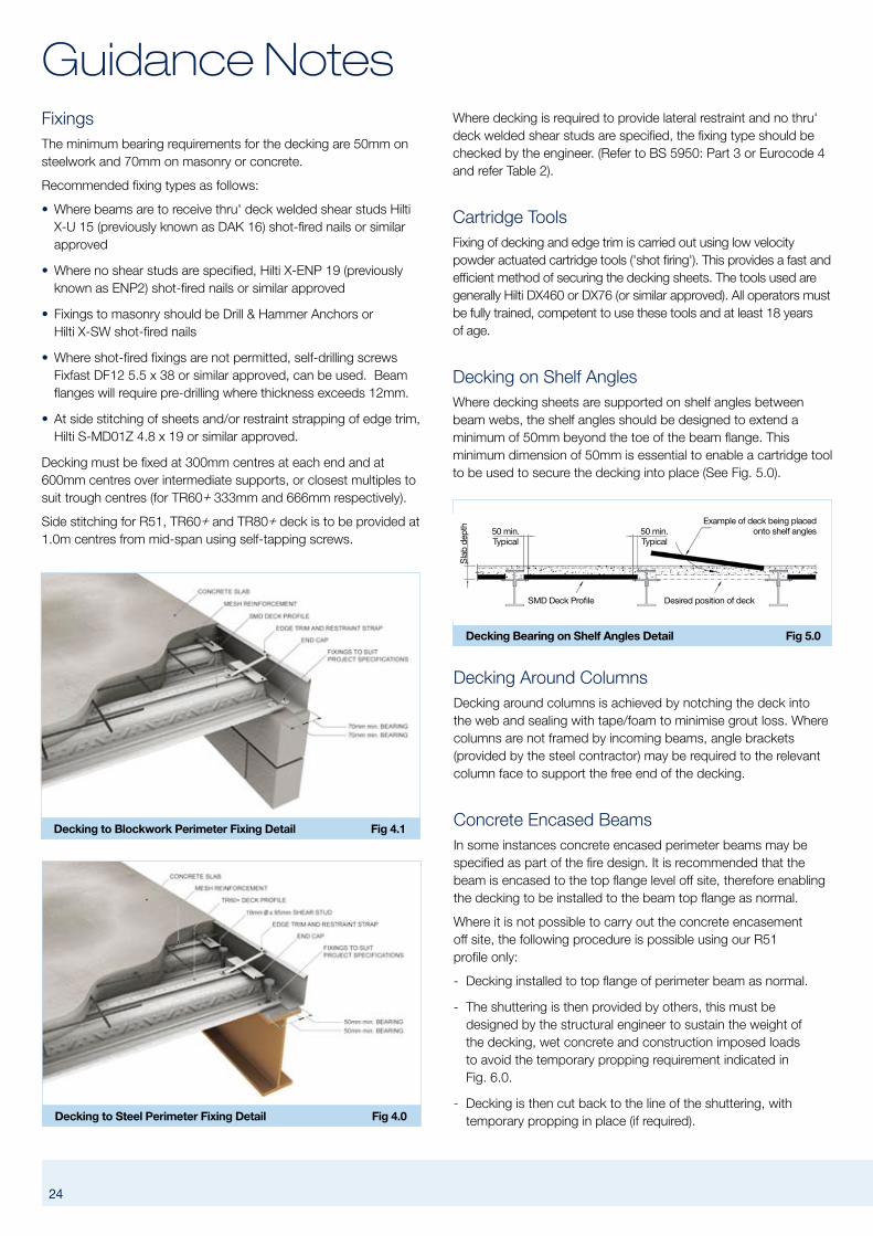
Decking Bearing on Shelf Angles Detail Fig 5.0
SMD Deck Profile Desired position of deck
Example of deck being placedonto shelf angles50 min.
Typical
Sla
b de
pth
50 min.Typical
Where decking is required to provide lateral restraint and no thru' deck welded shear studs are specified, the fixing type should be checked by the engineer. (Refer to BS 5950: Part 3 or Eurocode 4 and refer Table 2).
Cartridge ToolsFixing of decking and edge trim is carried out using low velocity powder actuated cartridge tools ('shot firing'). This provides a fast and efficient method of securing the decking sheets. The tools used are generally Hilti DX460 or DX76 (or similar approved). All operators must be fully trained, competent to use these tools and at least 18 years of age.
Decking on Shelf AnglesWhere decking sheets are supported on shelf angles between beam webs, the shelf angles should be designed to extend a minimum of 50mm beyond the toe of the beam flange. This minimum dimension of 50mm is essential to enable a cartridge tool to be used to secure the decking into place (See Fig. 5.0).
24 25
Decking to Blockwork Perimeter Fixing Detail Fig 4.1
Decking to Steel Perimeter Fixing Detail Fig 4.0
FixingsThe minimum bearing requirements for the decking are 50mm on steelwork and 70mm on masonry or concrete.
Recommended fixing types as follows:
• Where beams are to receive thru' deck welded shear studs Hilti X-U 15 (previously known as DAK 16) shot-fired nails or similar approved
• Where no shear studs are specified, Hilti X-ENP 19 (previously known as ENP2) shot-fired nails or similar approved
• Fixings to masonry should be Drill & Hammer Anchors or Hilti X-SW shot-fired nails
• Where shot-fired fixings are not permitted, self-drilling screws Fixfast DF12 5.5 x 38 or similar approved, can be used. Beam flanges will require pre-drilling where thickness exceeds 12mm.
• At side stitching of sheets and/or restraint strapping of edge trim, Hilti S-MD01Z 4.8 x 19 or similar approved.
Decking must be fixed at 300mm centres at each end and at 600mm centres over intermediate supports, or closest multiples to suit trough centres (for TR60+ 333mm and 666mm respectively).
Side stitching for R51, TR60+ and TR80+ deck is to be provided at 1.0m centres from mid-span using self-tapping screws.
Guidance Notes
Decking Around ColumnsDecking around columns is achieved by notching the deck into the web and sealing with tape/foam to minimise grout loss. Where columns are not framed by incoming beams, angle brackets (provided by the steel contractor) may be required to the relevant column face to support the free end of the decking.
Concrete Encased BeamsIn some instances concrete encased perimeter beams may be specified as part of the fire design. It is recommended that the beam is encased to the top flange level off site, therefore enabling the decking to be installed to the beam top flange as normal.
Where it is not possible to carry out the concrete encasement off site, the following procedure is possible using our R51 profile only:
- Decking installed to top flange of perimeter beam as normal.
- The shuttering is then provided by others, this must be designed by the structural engineer to sustain the weight of the decking, wet concrete and construction imposed loads to avoid the temporary propping requirement indicated in Fig. 6.0.
- Decking is then cut back to the line of the shuttering, with temporary propping in place (if required).

Concrete Encased Beam Detail Fig 6.0
R51 Deck Profile
Temporary propping by others
Reinforcementby others
Timber formworkby others
If propping not in place prior to fixing, decking to bear onto steelbeam & cut back once props are in place
Hairpin tie bar reinforcement – designed and supplied by othersMesh or TAB-DeckTM system
Sla
b de
pth
24 25
- In this detail the decking will not contribute to the shear resistance of the finished slab. Hairpin/tie bar reinforcement in the troughs of the decking profile will need to be designed/ specified by the engineer.
R51 Slab Edge and Flashings Fig 7.0
Sla
b de
pth
Sla
b de
pth
SMD R51 Deck Profile
SMD R51 Deck Profile
Restraint strap
Restraint strap
SMD flashing (Type 02)utilised when deck sheetfalls short of side bearing beam
Edge trim
Edge trim6 Ø min.(114 min)
30 min.
Rib flashing detail at perimeter beam Fig 8.1
Faceted edge trim detail to form a radius edge Fig 8.0
Edge Trim and FlashingsGalvanised edge trim is provided where requested around perimeter and void edges. This edge trim acts as permanent formwork only, to support the wet weight of concrete during construction.
Typically edge trim is supplied to site in lengths of 3.0m where it is then cut to suit. Edge trims are available in three gauges; 1.2mm, 1.6mm and 2.0mm. The material gauge is determined by the depth of the concrete slab and the extent of the slab overhang (refer Table 3 on page 21).
Edge trim can be either fixed to the end of the decking with self tapping screws (See Fig. 2) or to the main supporting structure using similar fixings as used to secure the decking (See Fig. 2.1).
Edge trim is to be fixed with a bearing of 50mm on steelwork or 70mm on masonry. It should be fixed at both ends and at 750mm centres along its length, with restraint straps fixed to the top edge at 750mm centres (or 500mm centres for slab depths of 200mm-300mm) – (See Fig. 7.0). For slab depths greater than 300mm consult SMD Technical Department.
Where edge trim is required to form a curve, straight lengths are provided to site and the edge trim is faceted on site to form the desired radius (refer Fig. 8.0).
At perimeter beams and intermediate beams parallel to the deck span (where shear studs are required), should the deck fall short or be positioned such that a trough is not located over the beam flange, galvanised mild steel flashings are provided to form a closure to the profile (refer Fig. 8.1 and 8.2). Flashings are available in 1.2mm, 1.6mm and 2.0mm gauges and are supplied to site in standard 3m lengths. The exact geometry and requirement for these flashings is detailed on SMD decking layout drawings.

26 27
Edge flashing detail at perimeter beam Fig 8.2
Guidance Notes
R51 Layout Details – Studs in pairs Fig 9.2
R51 Layout Details – Single Studs Fig 9.0
R51 Layout Details – Staggered Studs @ butt joint Fig 9.1
StudweldingGeneralShear studs are manufactured from low carbon steel with a minimum yield strength of 350 N/mm2 and a minimum ultimate tensile strength of 450 N/mm2 in accordance with BS EN ISO 13918. Standard 19mm diameter studs are available to achieve the following length after weld (LAW) 70mm, 95mm, 120mm, 145mm and 170mm. At the present time thru' deck welding of shear studs is restricted to 19mm dia studs or less.
Shear studs are welded through the decking trough onto the beam flange. Where possible, the shear studs should be placed on the centre line of the beam directly over the web to avoid burn through.
For a beam to be studwelded the flange thickness must be a minimum of 0.4 x the stud diameter = 7.6mm for standard 19mm diameter studs.
In some instances site welding may not be possible (ie. due to fire hazard or galvanized beams). One alternative is the Hilti HVB shear connector, fixed to the beam with shot-fired fixings using a DX750 or DX76 cartridge tool. The technical properties of the Hilti HVB differ greatly from the standard welded shear stud and therefore, should not be used in place of traditional welded shear studs without approval from the structural engineer. With Hilti HVB shear connectors, for the same degree of shear connection far greater quantities are required when compared to that of welded shear studs.
For further information on Hilti HVB Shear Connectors contact Hilti (UK) on 0800 886 100.
Shear Stud SpacingTo ensure the most effective use of shear studs, the dimensions and configurations shown in Figs. 9.0-9.5 should be used (In accordance with BS5950 Part 3 Section 3.1 or BS EN 1994-1-1).
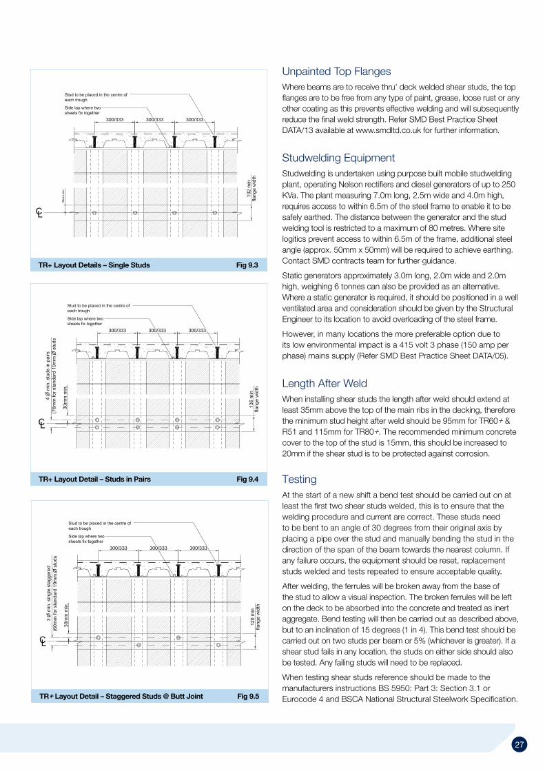
26 27
TR+ Layout Detail – Staggered Studs @ Butt Joint Fig 9.5
TR+ Layout Details – Single Studs Fig 9.3
TR+ Layout Detail – Studs in Pairs Fig 9.4
Unpainted Top FlangesWhere beams are to receive thru' deck welded shear studs, the top flanges are to be free from any type of paint, grease, loose rust or any other coating as this prevents effective welding and will subsequently reduce the final weld strength. Refer SMD Best Practice Sheet DATA/13 available at www.smdltd.co.uk for further information.
Studwelding EquipmentStudwelding is undertaken using purpose built mobile studwelding plant, operating Nelson rectifiers and diesel generators of up to 250 KVa. The plant measuring 7.0m long, 2.5m wide and 4.0m high, requires access to within 6.5m of the steel frame to enable it to be safely earthed. The distance between the generator and the stud welding tool is restricted to a maximum of 80 metres. Where site logitics prevent access to within 6.5m of the frame, additional steel angle (approx. 50mm x 50mm) will be required to achieve earthing. Contact SMD contracts team for further guidance.
Static generators approximately 3.0m long, 2.0m wide and 2.0m high, weighing 6 tonnes can also be provided as an alternative. Where a static generator is required, it should be positioned in a well ventilated area and consideration should be given by the Structural Engineer to its location to avoid overloading of the steel frame.
However, in many locations the more preferable option due to its low environmental impact is a 415 volt 3 phase (150 amp per phase) mains supply (Refer SMD Best Practice Sheet DATA/05).
Length After WeldWhen installing shear studs the length after weld should extend at least 35mm above the top of the main ribs in the decking, therefore the minimum stud height after weld should be 95mm for TR60+ & R51 and 115mm for TR80+. The recommended minimum concrete cover to the top of the stud is 15mm, this should be increased to 20mm if the shear stud is to be protected against corrosion.
TestingAt the start of a new shift a bend test should be carried out on at least the first two shear studs welded, this is to ensure that the welding procedure and current are correct. These studs need to be bent to an angle of 30 degrees from their original axis by placing a pipe over the stud and manually bending the stud in the direction of the span of the beam towards the nearest column. If any failure occurs, the equipment should be reset, replacement studs welded and tests repeated to ensure acceptable quality.
After welding, the ferrules will be broken away from the base of the stud to allow a visual inspection. The broken ferrules will be left on the deck to be absorbed into the concrete and treated as inert aggregate. Bend testing will then be carried out as described above, but to an inclination of 15 degrees (1 in 4). This bend test should be carried out on two studs per beam or 5% (whichever is greater). If a shear stud fails in any location, the studs on either side should also be tested. Any failing studs will need to be replaced.
When testing shear studs reference should be made to the manufacturers instructions BS 5950: Part 3: Section 3.1 or Eurocode 4 and BSCA National Structural Steelwork Specification.

28 29
Guidance NotesHealth and SafetyThe design, installation & completion of metal decking projects must be arranged so that the Health & Safety of the operatives undertaking the work, of other trades on site, and of members of the public is ensured.
A number of key factors are paramount in achieving this goal:
Management & SupervisionEnsure supervision is experienced in metal decking and that a suitable qualification such as SMSTS is held. Pre start visits allow agreement of programme, sequence and co-ordination with other trades. The planning and arrangement of deliveries to allow effective positioning on the steel frame (usually by the erectors) is essential in minimising issues with manual handling. Robust management of the workforce in relation to Safety, Quality & Production ensures safe completion. Handover procedures should be used to ensure works are complete for following trades.
Documentation All companies should have a framework of Policies & Procedures relating to the management of Health & Safety. SMD have developed a specific on site Health & Safety guide to assist operatives with trade specific guidance notes. Available to download from www.smdltd.co.uk
Contract specific safety documentation, including Method Statements, Risk Assessments & COSHH data sheets are available for all hazards / activities associated with the handling and fixing of SMD decking. The communication of this to the work force, ensures that all operatives understand the risks & the preventative measures that have been agreed. An initial toolbox talk on the method statement, followed by further weekly talks ensures procedures on site are appropriate to the ever changing construction environment. Records of induction & all toolbox talks should be maintained.
Typical hazards associated with metal decking & associated preventative measures are:
• Falls From Height – handrails, safety nets, suitable access to level
• Hot Work – exclusion zones, removal of flammable materials, fire extinguishers
• Use of Cartridge Tools – competency & training, PPE
• Hand Arm Vibration – management procedures
• Noise – PPE, management procedures, suitable work equipment
• Cuts to Hands – PPE
• Electrical Equipment – maintenance & 110v tools
• Falling Materials from height – trim tethers, tool tethers, loading out procedures
• Removal of Waste – skips, loading bays etc
• Adverse Weather – management control
Personal Protective Equipment (PPE)Task Specific PPE will be detailed in Risk Assessments however the minimum requirement will be:
• Hard Hat to EN397
• Safety Boots with heavy duty steel toecap and steel mid sole
• Hi Vis clothing to EN471 Class 1
• Cut Resistant Gloves to EN388 – Reflex K+ Kevlar Coated
• Hearing protection to EN352-1
• Tinted Welding Goggles
• Eye Protection to EN166 class 1 – clear lenses for cutting/ shot firing, smoked lenses for stud welding
Protection of Falls from HeightIn accordance with the Work at Height Regulations 2005 and given that for metal deck installation 'avoid work at height' and 'use work equipment to prevent falls' is not reasonably practicable, all contracts need to adopt a system of work that 'minimises the distance and consequence of a fall'. Methods of fall arrest used are safety netting for steel frame structures and airbags or similar for all other situations. Where safety netting is provided by SMD, this will be undertaken by FASET trained personnel. The contract specific method statement and risk assessment will detail the preferred methods for both fall arrest and installation.
Trained & Competent WorkforceEnsure that all operatives have received manufacturers training in the use of cartridge tools together with that for abrasive wheels, stud welding equipment, fire safety training and have achieved the appropriate level of CSCS qualification. Safety netters will be FASET trained and hold IPAF certificates if they are using MEWPs.
Information & Guidance for Other TradesDoN’T land packs on the frame in the incorrect position – It is essential that the decking packs are loaded out in the position indicated on SMD’s decking layout drawings.
DoN’T leave any unfixed decking sheets – Unfixed decking sheets pose a danger to others on site, ensure that as areas are being laid that they are not left unattended until fixed. Also at the end of each day, any unfixed sheets in decking packs should be secured down.
DoN’T put heavy loads on unprotected deck – Other trades must be made aware of the storage capacity of decking prior to concrete and the appropriate procedures for locating heavy loads on timbers laid on beam lines.
DoN’T cut holes/voids in the deck before concreting – It is very important where additional holes are required to be cut into the decking before concreting that you refer to the relevant section in this technical guide or contact the SMD Technical Department for guidance.

28 29
Options for Forming Voids Fig 10.0
DoN’T heap concrete or drop from any height – Following Concrete trades must be aware of good practice principles when pouring on suspended decks, so that overloading is avoided and any propping requirements are in place.
Further reading to assist with installation methods and safe working systems are:
• SCI Publication P300 – download from www.smdltd.co.uk
• BSCA code of practice for metal decking and studwelding (37/04)
• Industry standard best practice guidance sheets, available for download at www.smdltd.co.uk
Guidance for Following TradesDamaged DeckingCare should be taken when utilising the decking as a working platform, or storing materials for following trades. As any damage resulting from this will require a site inspection and the damaged sheets may require replacement.
Forming Service HolesWhen it is necessary to form service holes in a composite slab, SMD recommend the following general rules. For openings at right angles to the deck span:
1. Up to 250mm: Openings such as these require no special treatment. Prior to placing of concrete the opening is boxed out. When the slab has cured the deck is cut by others, using a non-percussive tool. (See Fig. 10.0)
2. Greater than 250mm but less than 700mm: Additional reinforcement is required around the opening, SMD recommend the design be generally in accordance with BS8110 or Eurocode 2. The forming of the hole is as item 1. (See Fig. 10.0) Items 1 and 2 relate to holes in isolation and not to a series of holes transverse to the direction of span, which should be considered as one large void. In these cases the metal decking should only be cut after the slab has cured.
3. Greater than 700mm: Structural trimming steelwork designed by others and supplied by the steelwork fabricator, will be required.
These are guidelines only and particular requirements should be checked by the project structural engineer. SMD’s responsibility excludes the design of any additional framing or slab reinforcement for holes or openings.
When forming holes in the decking, consideration needs to be given to health & safety. Due consideration should be given to protect against falling through holes. If possible handrail should be erected around the void. Alternatively, SMD can provide a temporary cover to the opening by decking over the void (unconcreted) for removal by others at a later date. For further guidance regarding service voids, including limitations for
positioning and trimming reinforcement design refer to MCRMA/SCI Publication P300: Composite Slabs and Beams using Steel Decking: Best Practice for Design and Construction.
Construction Joint Detail Fig 11.0
Cleaning the DeckingPrior to the concrete being placed, the decking should be cleared by others of any debris, grease and/or dirt which could adversely affect the bond between the concrete and the decking. Typically, ceramic ferrules left over from the shear studding process can be left distributed over the decking surface and lost within the concrete pour. Final clarification should be sought from the project structural engineer (refer Concrete Society – Good Concrete Guide 5 for further guidance).
Construction JointsWith composite floor slabs, it is possible to achieve continuous concrete pours in excess of 1,000m2.
Where construction joints are required, these should always be formed as close as possible to the deck support over which the decking sheets are butt-jointed. The distance from the centre of the butt end support to the stop end should never exceed one-third of the span between the supports (See Fig. 11.0).

30 31
Guidance Notes
Mid-Bay Slab Deflection Fig 12.0
Section Through Slab Deflection Fig 12.1
Surface Flatness / FinishThe concrete finish specified should relate to the floor finishes being applied so as to provide a key, where required, or compatibility with any curing membranes.
Normally a ‘trowel’ finish is applied to upper floor concrete using a skip float (defined as U1 in 3rd edition of the National Structural Concrete Specification for building construction). This will leave trowel marks at the edges and occasionally reinforcement ripple on the surface, but generally these will be covered by the raised floor or make up screed. Where a ‘pan’ or ‘power float’ finish is required, this can be provided although it must be specified in the context of the previous section i.e. power floating will make the surface appear smoother and flatter but not level. Generally the surface regularly achievable is +/-10mm under a 2m straight edge (SR3 to BS 8204-1). Please refer to the ‘Concrete Society Good Concrete Guide 5’ for further information.
ReinforcementMesh and loose bar reinforcement will require detailing by the structural engineer, in good time to allow for procurement and transportation to site. Mesh is intended as a method of crack control and not to eliminate cracking. Depending on the mesh type/deck type and slab depth it may be necessary to lay the mesh directly onto the top of the profile (nesting) due to the cumulative build up of cover and available space.
ProppingWhilst every effort is made to eliminate propping by increasing deck gauge or additional support, occasionally the spans detailed are beyond the capabilities of the decking during the construction phase. Any props required will be shown on the SMD drawings (where provided). It is the responsibility of the Principal Contractor to obtain a temporary works design approval for any propping and to ensure that they are installed prior to concreting. See Design section (pages 19 and 20) for further guidance on temporary propping.
Placing and CompactingDue to the notable differences in pouring concrete on suspended metal decked slabs to that of traditional Ground Floor slabs; it is highly recommended that a competent concrete contractor with experience in pouring concrete onto metal decking (such as SMD) is used for this section of the works. The recommended means of pouring concrete onto metal decking is by pumping. Where the concrete is being transferred into position using barrows or by lines of pipe for pumping, boards should be used to provide a load-spreading platform across the deck, thus reducing the risk of accidental damage to the profile.
The wet concrete must not be heaped, or dropped from a height exceeding 1.0m in any area during the laying sequence.
When poured in the same direction as the decking span, concrete should be poured evenly over 2 spans starting at beam positions.
Concrete – The Complete PackageSMD can provide a ‘one stop’ floor solution using dedicated floor laying teams co-ordinated by the same site manager that oversees the decking and shear stud installation. This not only ensures continuity of service for the client but also ensures a quick, seamless process of delivering a complete Composite Floor Solution.
When detailing and specifying concrete to suspended upper floors it is vital that consideration is given to the fact that the supporting structure (both deck and steelwork) will deflect under load, which in turn will affect the achievable tolerances. Detailed information can be found in ‘Concrete Society Good Practice Guide No. 5’ but the key points worth noting are:
DatumUnlike ground floor slabs, concrete on decking cannot be laid to a datum due to the deck and steel deflection (refer Fig.12.0 and 12.1). Concrete is laid to a constant thickness and depending on beam/deck span may result in the top of the concrete being up to 30/40mm below theoretical design datum, whilst still maintaining the correct design thickness. The Concrete Society state that a datum level of +/-15mm can be achieved around columns only. Please refer to the best practice sheet DATA /10 available to download at www.smdltd.co.uk. Unless raised access flooring is being installed it is recommended that a top up level screed is used to achieve a datum level finish.

30 31
1.8mm
2mm50mm
TAB-DeckTM HE 1/50 Fibre by ArcelorMittal Fig 14.0
When concrete is poured in a direction at right angles to the span it should be placed first at the edge where a decking sheet is supported by the underlap of an adjacent sheet. This helps to ensure that the longitudinal side laps between sheets remain closed and hence reduces grout loss. The concrete should be well compacted using either a vibrating beam or plate vibrator, particularly locally around shear studs.
Minimising Grout LossDecking sheets are designed to butt join with the ribs lined through to avoid gaps and excessive grout loss. Gaps in excess of 5mm should be sealed using either tape or expanding foam. Where gaps are less than 5mm no special provision is required as minimal leakage is experienced.
Where trapezoidal (TR60+ or TR80+) decking sheets end at the perimeter of the building or at internal voids, the ends of the sheets are sealed with 0.7mm gauge galvanized end caps or polystyrene inserts. These end caps will also be required where you have a change in span direction (See Fig. 13.0). Due to the small re-entrant rib size of the R51 profile, sheets are typically sealed using tape or expandable foam.
As decking is not intended to provide a fully tanked solution there will be small quantities of grout and water loss. If the soffit and trim is intended to be fully exposed in its final condition then consideration should be given, at tender stage, to the taping of all joints prior to concreting. Contact SMD Construction Department for further information.
CuringDuring the curing process the moisture within the slab should not be allowed to evaporate too quickly. Consideration should be given to the use of spray applied curing agents, to limit rate of moisture evaporation.
For further guidance on the concreting process, refer Concrete Society Good Concrete Guide 5: Composite Concrete Slabs on Steel Decking.
TAB-DeckTM – Fibre Concrete TAB-Deck™ fibre reinforced concrete should be installed, cured and finished in exactly the same way as non-fibre reinforced concrete. The only fibre that has been extensively tested for use on TAB-Deck™ projects is Arcelor Mittal Wire Solutions HE 1/50 Steel fibre at a dosage of 30kg/m3.
Concrete DesignThe specific mix design will always depend on the local materials available but should follow these basic guidelines:
Cement – minimum 350kg/m3 of CEM I or CEM IIIA Aggregates – maximum 20mm Fines Content – minimum 450kg/m3 of smaller than 200μ including cementitious content Water/Cement Ratio ≤ 0.50 Minimum Slump – 70mm (before the addition of steel fibres and super-plasticizer)
ArcelorMittal Wire Solutions can provide advice on individual mix designs and check suitability for specific projects.
MixingThe best method for integrating the HE 1/50 steel fibre into the fresh concrete is by blast machines, available on request from ArcelorMittal Wire Solutions. This is a self sufficient operation where the steel fibres are blown into the preloaded ready mix truck allowing for easy homogenisation of the steel fibres into the concrete mix.
Alternatively, the steel fibres may be loaded via mobile conveyor belts or placed on the aggregate belt at the ready mix plant.
End Cap Detail Fig 13.0
HE 1/50 Technical SpecificationWire dimension 1.0mm (+/- 0.04mm)Fibre Length 50mm (+/- 2-3mm)Number of Fibres per kg 3100 NoTotal fibre length per 10kg 1575mTensile strength of drawn wire 1100 N/mm2Rod wire C4D or C7D according to EN 10016-2
For further information and design guidance contact Arcelor Mittal Wire Solutions or SMD for a copy of the TAB-Deck™ Design Guide. Alternatively, this can be downloaded at www.smdltd.co.uk

32 33
TR+ 'Wedge Nut' Installation Fig 15.3
Guidance Notes
R51 'Wedge Nut' Detail Fig 15.0
TR+ 'Wedge Nut' Detail Fig 15.1
Service FixingsSpecificationPlease note: Soffit fixings are only to be installed/loaded after the concrete slab has gained specified design strength.
SMD profiles offer the opportunity of utilising soffit fixings for services, ceilings etc. to suit drop rod thread sizes of 6mm, 8mm and 10mm for loads up to 2.0kN. To avoid possible localised overloading of the slab, fixings should not be locally grouped. As a general guide it is recommended that fixings be on a nominal 600mm grid. Design advice for closer groupings should be sought from SMD Technical Department as this depends on slab depths, loadings etc.
See Figs. 15.0 and 15.1 for details.
Installation of Service Fixing1 Ensure you have selected the correct wedge nut.
2 Thread wedge onto the required rod.
3 Insert wedge into the dovetail rib from below and rotate through
AvailabilityThese fixings are available from Lindapter International Ltd on 01274 521444. The ‘V’ Nut is to be used on the SMD R51 profile and the ‘TR60’ Nut is to be used for both the TR60+ and TR80+ profiles. Guidance on the use of these fixings is available from Lindapter International Ltd – www.lindapter.com
Other fixings and proprietary anchors are also available. These should be used in accordance with fixing manufacturers guidance. The approval of such fixings should be sought from the project structural engineer.
R51 'Wedge Nut' Installation Fig 15.2
90 degrees so that the sloped face of the wedge bears on the decking rib.
4 The rod should then be finger tightened up to the roof of the dovetail or a washer set against the soffit of the decking.
5 Use mechanical tightening to finish, refer Fig. 15.2 and 15.3.

32 33
Step with high level formed with Edge Trim Fig 16.0
Further ReadingBCSA Publication 37/04: Code of practice for Metal Decking and Stud Welding
MCRMA/SCI Technical Paper No. 13/SCI P300 REVISED EDITIoN. Composite slabs and beams using steel decking: Best practice for design and construction
British Standard BS 5950: Structural use of steelwork in building
Part 3: Design in composite construction, Section 3.1: 1990 Code of Practice for design of simple and continuous composite beams
Part 4: Code of Practice for design of composite slabs with profiled sheeting
Part 6: Code of Practice for design of light gauge profiled steel sheeting
Part 8: Code of practice for fire resistant design
Eurocodes and all relevant National Annexe Documents: BS EN 1994 – Design of Composite Steel and Concrete Structures
SCI Publication 056: (2nd Edition). The Fire Resistance of Composite Floors with Steel Decking
SCI Publication 076: Design guide on the vibration of floors
SCI Publication P285: Benefits of Composite Flooring
SCI Publication 331: Design guide on the vibration of floors in Hospitals
SCI Publication 322: Acoustic performance of composite floors
SCI Publication P354: Design of floors for Vibration: A New Approach
SCI Publication P372: Acoustic Detailing for Steel Construction
SCI AD Note 150 – Composite Floors: Wheel loads from Forklift Trucks
SCI AD Note 247 – Use of Composite Construction in an aggressive environment
SCI AD Note 343 – Position of reinforcing mesh relative to stud shear connectors in composite slabs
SCI AD Note 344 – Levelling techniques for composite floors
Concrete Society Good Concrete Guide 5: Composite concrete slabs on steel decking – Guidance on construction and associated design considerations
Robust Details Ltd: Robust Details Handbook
Other Typical DetailsThis section covers further standard details that are often used to meet specific requirements and are not already covered in this document.
Step in deck level at beam positionWhere a step in the deck/slab level is required. This should be located at supporting beam positions, with angles provided to support the lower level decking. Depending on the difference in level and requirement for slab continuity, the higher level slab may be formed using standard edge trim (refer Fig. 16.0) or formed traditionally by following trades (refer Fig. 16.1). Decking on angle fixed to web of beam Fig 16.2
Decking on angles to beam websTo reduce the structural zone it is sometimes necessary to install the decking onto angles fixed to the beam webs (see page 24 and refer to Fig 16.2). Where the decking spans parallel to the beam web, it may be possible depending on spacing of secondary beams to utilise a 2.0mm gauge flashing to avoid the requirement for a structural angle.
Step with high level formed traditionally Fig 16.1

Perimeter Toeboard fixed to vertical face of trim Fig 16.6
Guidance Notes
34 35
Large side cantilever with stub beams Fig 16.4
Shear Stud Detail at Butt Joints (TR+ profiles) Fig 16.3
3D Stud Detail at Butt JointsPage 26-27 of this document shows the 2D standard details for shear stud configurations in accordance with BS5950 and Eurocode 4. Fig 16.3 is a 3D detail of the typical staggered stud configuration used at butt joints.
Alternative detail for large overhangsWhere overhangs are required on edges parallel with the deck span, these are typically formed with standard edge trim (refer pages 20 and 21). Where edge dimensions are in excess of figures shown in Table 3, temporary propping is required to the edge prior to installation. Alternatively, additional stub beams in line with secondary steels can be provided by the steelwork contractor. These large edges can then be formed in decking with trim stitched to the side (refer Fig 16.4).
Support detail at Existing Concrete / Core WallsShelf angles are required where decking spans up against existing concrete or core walls (refer Fig 16.5)
Fig 16.7 – the toeboard is a secondary trim fixed to a horizontal leg provided along the top of the standard trim. This has limitations due to the access required to fix the edge trim to supporting steelwork, but is easier to remove upon completion.
Perimeter ToeboardPerimeter toeboard is usually provided as part of the edge protection system. However, in some instances it is necessary for this to be provided as an addition to the perimeter edge trim. When required, there are two common options:
Fig 16.6 – the toeboard consists of a flat trim fixed flush to the outer vertical face of the edge trim, for removal by others.
Decking on RSA fixed to Concrete Core Fig 16.5
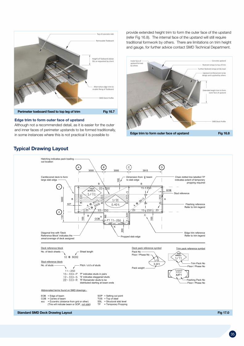
Standard SMD Deck Drawing Layout Fig 17.0
Perimeter toeboard fixed to top leg of trim Fig 16.7
34 35
Typical Drawing Layout
Edge trim to form outer face of upstand Fig 16.8
provide extended height trim to form the outer face of the upstand (refer Fig 16.8). The internal face of the upstand will still require traditional formwork by others. There are limitations on trim height and gauge, for further advice contact SMD Technical Department.
Edge trim to form outer face of upstandAlthough not a recommended detail, as it is easier for the outer and inner faces of perimeter upstands to be formed traditionally, in some instances where this is not practical it is possible to

© Structural Metal Decks Limited 2010. Liable to change without notice.
UK Head Office Structural Metal Decks LtdThe Outlook Ling Road Tower Park Poole Dorset BH12 4PY UKTel: +44 (0) 1202 718898 Fax: +44 (0) 1202 714980 Email: [email protected]
Midlands Logistics Centre Structural Metal Decks Ltd Unit 107 Marchington Industrial Estate Stubby Lane Marchington Uttoxeter ST14 8LP UKEmail: [email protected]
United Arab Emirates Structural Metal Decks Ltd PO Box 21023 Ajman U.A.E.Tel: +44 (0) 1202 718898 Fax: +44 (0) 1202 714980 Email: [email protected]
Department [email protected]@[email protected]@smdltd.co.uk
www.smdltd.co.uk