Embed Size (px)
Citation preview
SMD PCB Terminal BlocksWe Connect Your Light
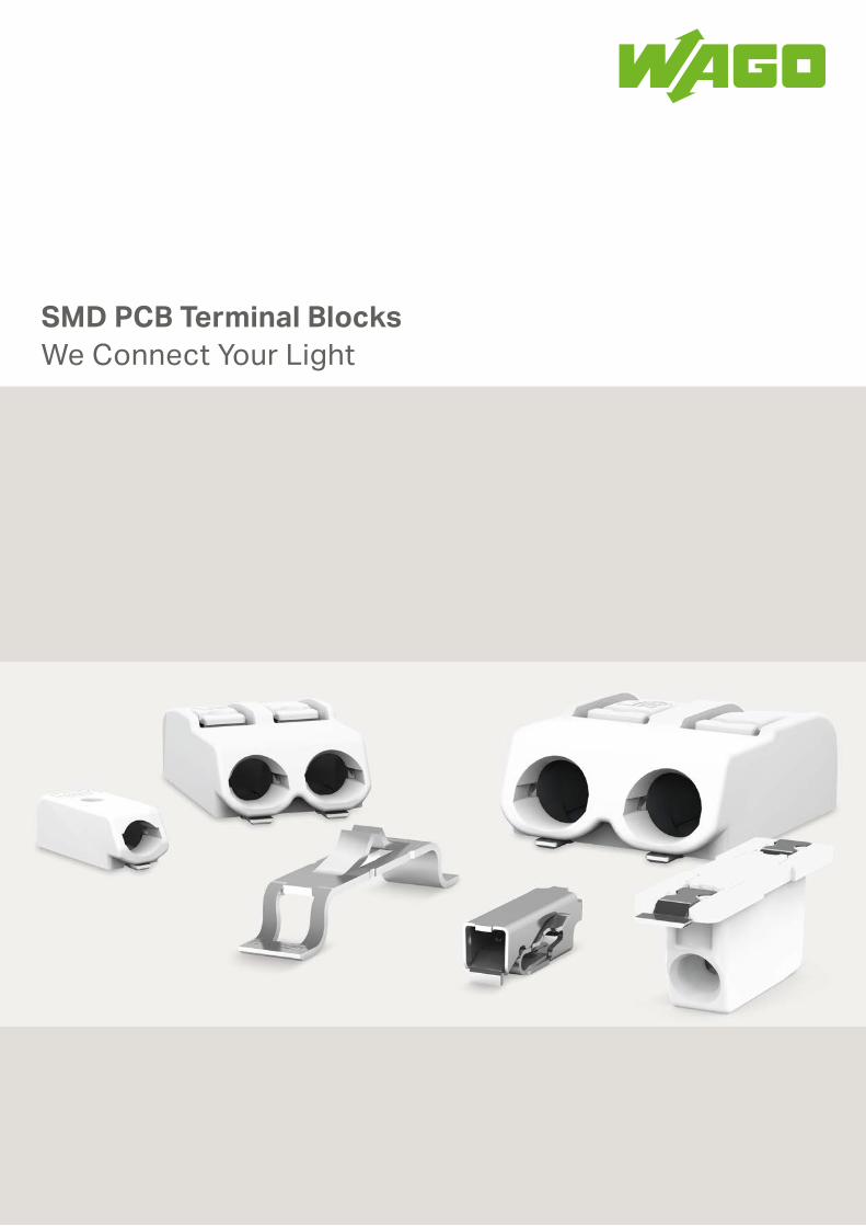
SMD PCB TERMINAL BLOCKSA compact and low-profile PCB connection is required for optimal uniform light distribution, that minimizes shadowing. WAGO’s SMD PCB terminal blocks, with their combination of a flat design and wide application scope, fully satisfy these demands. Furthermore, assembling 1-, 2- and 3-pole terminal blocks (2059, 2060 and 2061
Series) without losing any poles provides complete flexibility with a reduced number of variants. All sur-face-mount PCB terminal blocks come in tape-and-reel packaging for full integration into an automated assem-bly process.
Applications
The numerous advantages of WAGO’s SMD line of PCB terminal blocks allow them to support a wide range of applications. From the newest generation of ultra-flat LED drivers via compact, conventionally wired LED spot-lights, right up to automatically (front- or back-side) wired, recessed ceiling luminaires, WAGO’s SMD PCB terminal
Advantages:
• Low profiles minimize on-board LED shadowing
• Insert solid conductors via push-in termination
• Terminal strips of different lengths can be assembled without pole loss, reducing the number of vari-ants and lowering production costs
• Available in 1–3 pole configurations
• Delivery in tape-and-reel pack- aging for full integration into SMT soldering process
• Lower costs via automated pick-and-place assembly
blocks provide the perfect connection between driver and module. The terminal blocks accommodate a broad range of con-ductors and carry major international approvals making them highly versatile for worldwide applications.
Auto
mat
ed a
ssem
bly
Prin
ting
(sol
der)
SMD components
SMD
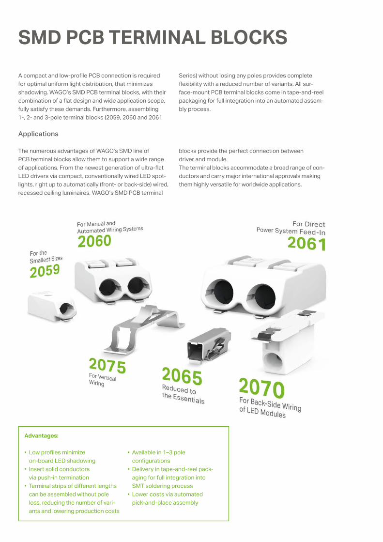
SURFACE-MOUNT TECHNOLOGY Surface-Mount Technology (SMT) means soldering electronic components directly onto PCB surface pads without drilling holes. The basic SMT process consists of applying solder paste to the PCB via solder dispensing equipment, screen or
Reflow Soldering Process
stencil printing. SMT assembly is performed using fully automated placement machines. Surface-mount com-ponents are soldered to the board in convection or vapor phase ovens.
<__ __><__ __>
<_ _>
<> ( )
<_ _>
3
L7.47.9
6.5
2.7
1
2.58.7
0.4
0.5
0.8 0.75
1.4 3
0.3
<_>
<<___ ___>
<___>
<___
><
___
>
<>
()
><__>
(__>
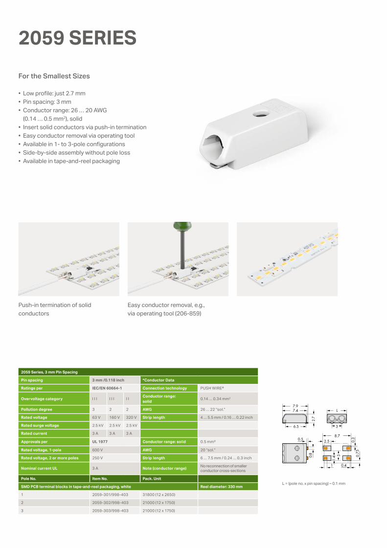
2059 SERIES
• Low profile: just 2.7 mm • Pin spacing: 3 mm• Conductor range: 26 … 20 AWG
(0.14 … 0.5 mm2), solid• Insert solid conductors via push-in termination• Easy conductor removal via operating tool• Available in 1- to 3-pole configurations • Side-by-side assembly without pole loss• Available in tape-and-reel packaging
Push-in termination of solid conductors
Easy conductor removal, e.g., via operating tool (206-859)
For the Smallest Sizes
2059 Series, 3 mm Pin Spacing
Pin spacing 3 mm /0.118 inch *Conductor Data
Ratings per IEC/EN 60664-1 Connection technology PUSH WIRE®
Overvoltage category I I I I I I I I Conductor range: solid 0.14 … 0.34 mm2
Pollution degree 3 2 2 AWG 26 … 22 “sol.”
Rated voltage 63 V 160 V 320 V Strip length 4 … 5.5 mm / 0.16 … 0.22 inch
Rated surge voltage 2.5 kV 2.5 kV 2.5 kV
Rated current 3 A 3 A 3 A
Approvals per UL 1977 Conductor range: solid 0.5 mm²
Rated voltage, 1-pole 600 V AWG 20 “sol.”
Rated voltage, 2 or more poles 250 V Strip length 6 … 7.5 mm / 0.24 … 0.3 inch
Nominal current UL 3 A Note (conductor range) No reconnection of smaller conductor cross-sections
Pole No. Item No. Pack. Unit
SMD PCB terminal blocks in tape-and-reel packaging, white Reel diameter: 330 mm
1 2059-301/998-403 31800 (12 x 2650)
2 2059-302/998-403 21000 (12 x 1750)
3 2059-303/998-403 21000 (12 x 1750)
L = (pole no. x pin spacing) – 0.1 mm
© rgb2012/Fotolia.com
<_
<_
<_ 0.6
2.75
max. 20 << max. 20
min. 2.4 - max. 3.3 (15.3)min. 4.6 - max. 5.1 (17.5)min. 7.6 - max. 8.2 (20.5)
<<
<______________________<
<_
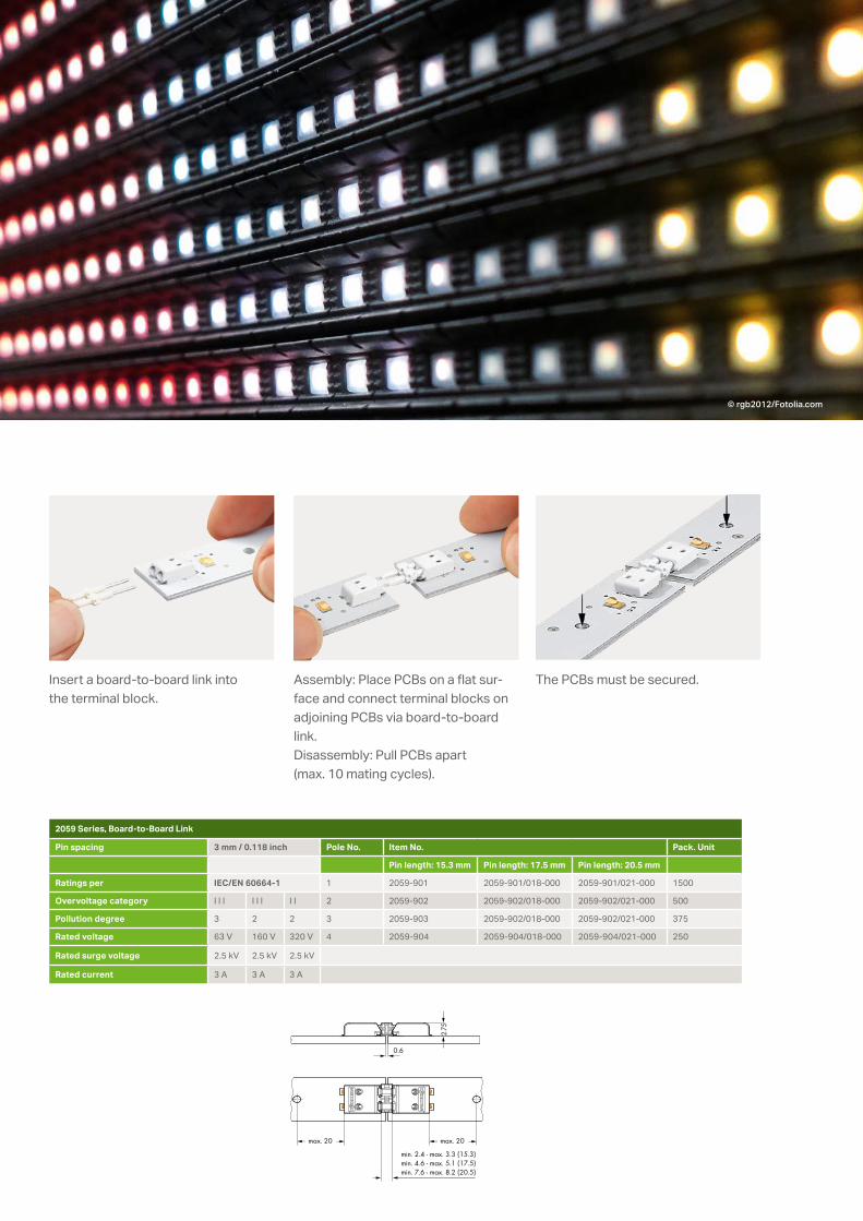
Assembly: Place PCBs on a flat sur-face and connect terminal blocks on adjoining PCBs via board-to-board link. Disassembly: Pull PCBs apart (max. 10 mating cycles).
The PCBs must be secured. Insert a board-to-board link into the terminal block.
2059 Series, Board-to-Board Link
Pin spacing 3 mm / 0.118 inch Pole No. Item No. Pack. Unit
Pin length: 15.3 mm Pin length: 17.5 mm Pin length: 20.5 mm
Ratings per IEC/EN 60664-1 1 2059-901 2059-901/018-000 2059-901/021-000 1500
Overvoltage category I I I I I I I I 2 2059-902 2059-902/018-000 2059-902/021-000 500
Pollution degree 3 2 2 3 2059-903 2059-902/018-000 2059-902/021-000 375
Rated voltage 63 V 160 V 320 V 4 2059-904 2059-904/018-000 2059-904/021-000 250
Rated surge voltage 2.5 kV 2.5 kV 2.5 kV
Rated current 3 A 3 A 3 A
<2.1> 1.
2
2.2
<____
>
L<___ ___>
4< >
<_<6.1 _> 14<__________ _______>
6<_ _> 3.5 <>
4<2 <
>> 0.
4<
___
>
0.4 <___>>0.
95<
___
<__
)
4( )
<_______ _______>12.7<_____ ____>
11.1<____ ____>
4<
>
4.5
<>
13.1
0.4___>
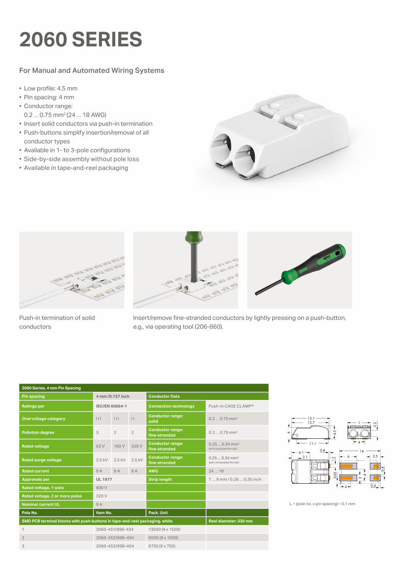
2060 SERIES
• Low profile: 4.5 mm• Pin spacing: 4 mm• Conductor range:
0.2 … 0.75 mm2 (24 … 18 AWG)• Insert solid conductors via push-in termination• Push-buttons simplify insertion/removal of all
conductor types• Available in 1- to 3-pole configurations • Side-by-side assembly without pole loss• Available in tape-and-reel packaging
Push-in termination of solid conductors
Insert/remove fine-stranded conductors by lightly pressing on a push-button, e.g., via operating tool (206-860).
For Manual and Automated Wiring Systems
2060 Series, 4 mm Pin Spacing
Pin spacing 4 mm /0.157 inch Conductor Data
Ratings per IEC/EN 60664-1 Connection technology Push-in CAGE CLAMP®
Overvoltage category I I I I I I I I Conductor range: solid 0.2 … 0.75 mm2
Pollution degree 3 2 2 Conductor range: fine-stranded 0.2 … 0.75 mm2
Rated voltage 63 V 160 V 320 V Conductor range:fine-stranded
0.25 ... 0.34 mm2
(with insulated ferrule)
Rated surge voltage 2.5 kV 2.5 kV 2.5 kV Conductor range:fine-stranded
0.25 ... 0.34 mm2
(with uninsulated ferrule)
Rated current 9 A 9 A 9 A AWG 24 … 18
Approvals per UL 1977 Strip length 7 … 9 mm / 0.28 … 0.35 inch
Rated voltage, 1-pole 600 V
Rated voltage, 2 or more poles 320 V
Nominal current UL 9 A
Pole No. Item No. Pack. Unit
SMD PCB terminal blocks with push-buttons in tape-and-reel packaging, white Reel diameter: 330 mm
1 2060-451/998-404 13500 (9 x 1500)
2 2060-452/998-404 9000 (9 x 1000)
3 2060-453/998-404 6750 (9 x 750)
L = (pole no. x pin spacing) – 0.1 mm
max. 21<_____
<_____________________
______>max. 21<_____ ______>
4.5<
>
> min. 4.4 … max. 6.4
<_____________________> min. 4.4 … max. 6.4
0.4 <___>2.1> 1.
2
<_<6.1 _> 14<__________ _______>
6<_ _> 3.5 <>
<2
>
0.4
<___
>
0.4 <___>>0.
95<
__
2.2
<____
>
11.9<______ ______>
8<___ ___>
4( )
<___
8<
___
___>
>
<_______ _______>12.7<_____ ____>
11.1<____ ____>
4<
>
4.5
<>
13.1
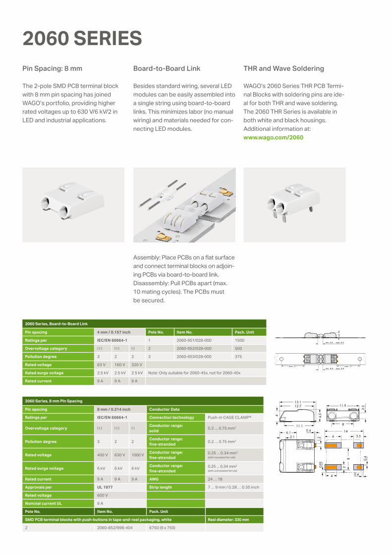
2060 SERIES
The 2-pole SMD PCB terminal block with 8 mm pin spacing has joined WAGO’s portfolio, providing higher rated voltages up to 630 V/6 kV/2 in LED and industrial applications.
Besides standard wiring, several LED modules can be easily assembled into a single string using board-to-board links. This minimizes labor (no manual wiring) and materials needed for con-necting LED modules.
WAGO’s 2060 Series THR PCB Termi-nal Blocks with soldering pins are ide-al for both THR and wave soldering. The 2060 THR Series is available in both white and black housings. Additional information at: www.wago.com/2060
Assembly: Place PCBs on a flat surface and connect terminal blocks on adjoin-ing PCBs via board-to-board link. Disassembly: Pull PCBs apart (max. 10 mating cycles). The PCBs must be secured.
Board-to-Board LinkPin Spacing: 8 mm THR and Wave Soldering
2060 Series, Board-to-Board Link
Pin spacing 4 mm / 0.157 inch Pole No. Item No. Pack. Unit
Ratings per IEC/EN 60664-1 1 2060-951/028-000 1500
Overvoltage category I I I I I I I I 2 2060-952/028-000 500
Pollution degree 3 2 2 3 2060-953/028-000 375
Rated voltage 63 V 160 V 320 V
Rated surge voltage 2.5 kV 2.5 kV 2.5 kV Note: Only suitable for 2060-45x, not for 2060-40x
Rated current 9 A 9 A 9 A
2060 Series, 8 mm Pin Spacing
Pin spacing 8 mm / 0.314 inch Conductor Data
Ratings per IEC/EN 60664-1 Connection technology Push-in CAGE CLAMP®
Overvoltage category I I I I I I I I Conductor range: solid 0.2 … 0.75 mm2
Pollution degree 3 2 2 Conductor range: fine-stranded 0.2 … 0.75 mm2
Rated voltage 400 V 630 V 1000 V Conductor range: fine-stranded
0.25 ... 0.34 mm2
(with insulated ferrule)
Rated surge voltage 6 kV 6 kV 6 kV Conductor range: fine-stranded
0.25 ... 0.34 mm2
(with uninsulated ferrule)
Rated current 9 A 9 A 9 A AWG 24 … 18
Approvals per UL 1977 Strip length 7 … 9 mm / 0.28 … 0.35 inch
Rated voltage 600 V
Nominal current UL 9 A
Pole No. Item No. Pack. Unit
SMD PCB terminal blocks with push-buttons in tape-and-reel packaging, white Reel diameter: 330 mm
2 2060-852/998-404 6750 (9 x 750)
>
<_______ _______>15.2<_____ _____>
13.8<____ _____>
0.6 <____>2.2>
5.2
<>
5.6
<>
15.8
3.2
<____
>
L<___ ___>
6< >
<_<6.5 _> 17<_________ _________>
6.5<_ _> 4.5 <>
6<2.
1<
> 0.4
<___
>
2.7 <_>
)<
<
<2.
4
1.8
<> 4.6
>
1.6
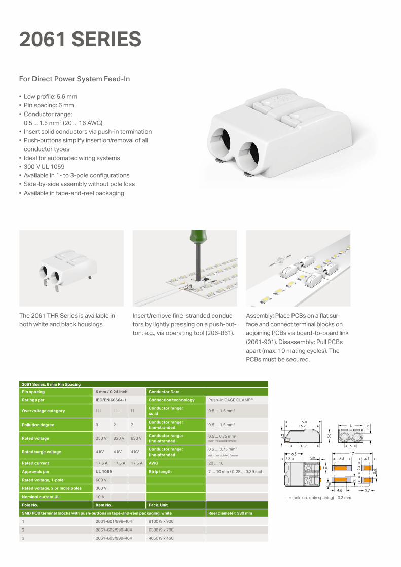
• Low profile: 5.6 mm• Pin spacing: 6 mm• Conductor range:
0.5 … 1.5 mm2 (20 … 16 AWG)• Insert solid conductors via push-in termination• Push-buttons simplify insertion/removal of all
conductor types• Ideal for automated wiring systems• 300 V UL 1059• Available in 1- to 3-pole configurations• Side-by-side assembly without pole loss• Available in tape-and-reel packaging
2061 SERIES
Insert/remove fine-stranded conduc-tors by lightly pressing on a push-but-ton, e.g., via operating tool (206-861).
The 2061 THR Series is available in both white and black housings.
For Direct Power System Feed-In
2061 Series, 6 mm Pin Spacing
Pin spacing 6 mm / 0.24 inch Conductor Data
Ratings per IEC/EN 60664-1 Connection technology Push-in CAGE CLAMP®
Overvoltage category I I I I I I I I Conductor range: solid 0.5 … 1.5 mm2
Pollution degree 3 2 2 Conductor range: fine-stranded 0.5 … 1.5 mm2
Rated voltage 250 V 320 V 630 V Conductor range: fine-stranded
0.5 ... 0.75 mm2
(with insulated ferrule)
Rated surge voltage 4 kV 4 kV 4 kV Conductor range: fine-stranded
0.5 … 0.75 mm2
(with uninsulated ferrule)
Rated current 17.5 A 17.5 A 17.5 A AWG 20 … 16
Approvals per UL 1059 Strip length 7 … 10 mm / 0.28 … 0.39 inch
Rated voltage, 1-pole 600 V
Rated voltage, 2 or more poles 300 V
Nominal current UL 10 A
Pole No. Item No. Pack. Unit
SMD PCB terminal blocks with push-buttons in tape-and-reel packaging, white Reel diameter: 330 mm
1 2061-601/998-404 8100 (9 x 900)
2 2061-602/998-404 6300 (9 x 700)
3 2061-603/998-404 4050 (9 x 450)
L = (pole no. x pin spacing) – 0.3 mm
Assembly: Place PCBs on a flat sur-face and connect terminal blocks on adjoining PCBs via board-to-board link (2061-901). Disassembly: Pull PCBs apart (max. 10 mating cycles). The PCBs must be secured.
2.7
8
<>
<___ ___>
87.8
<___ <___<___ <___ <
>2.
3
<>
2<__>
0.2
<___>
0.15
<>
2.9
5.1< <
4.6< <
7.8<___ <___
6.9<__ <__
7.95<__ <__
6.5<___ ___>
4.4 2.1<_ <__>
4.2 2.9<_ <__>3.6 2.3< (>
NOTE: Terminal block without insulation housing!Protection against accidental contact must be provided at voltages higher than low voltages (e.g., SELV/PELV) for the relevant application.
2065 Series
Technical Data Conductor Data
Ratings per IEC/EN 60664-1 Connection technology Push-in CAGE CLAMP®
Overvoltage category I I I I I I I I Conductor range: solid 0.2 … 0.75 mm2
Pollution degree 3 2 2 Conductor range: fine-stranded
0.2 … 0.75 mm2
Rated voltage* 320 V 320 V 630 V
Rated surge voltage 4 kV 4 kV 4 kV
Rated current 9 A 9 A 9 A
AWG 24 … 18
Strip length min. 7.5 mm / 0.3 inch
Pole No. Item No.
SMD PCB terminal blocks with push-buttons in tape-and-reel packaging Reel diameter: 330 mm
1 2065-100/998-403
*Rated voltage for 6.5 mm pin spacing Any layout deviation must meet the insulation coordination safety standards (EN/IEC 60664-1) or end device standard requirements.
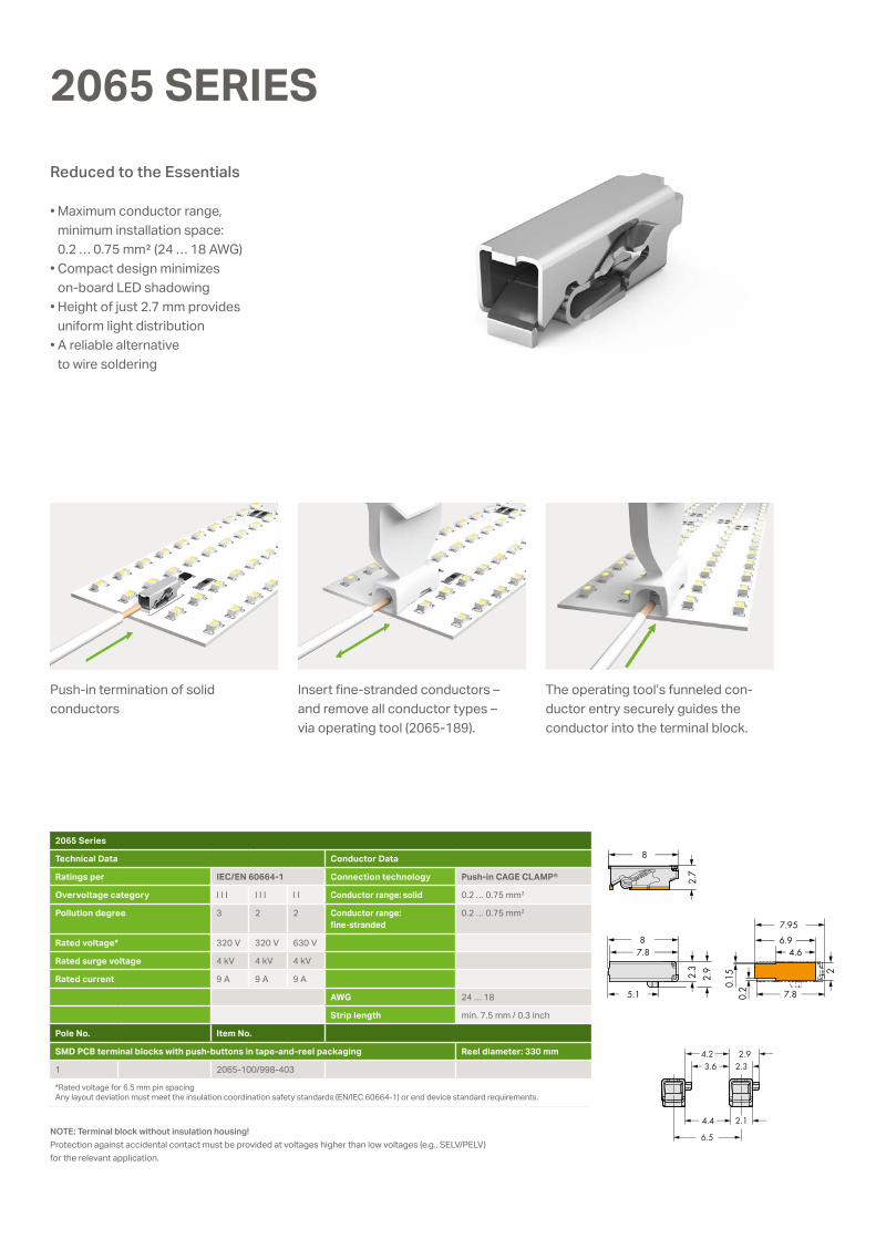
2065 SERIES
Push-in termination of solid conductors
Insert fine-stranded conductors – and remove all conductor types – via operating tool (2065-189).
The operating tool’s funneled con-ductor entry securely guides the conductor into the terminal block.
• Maximum conductor range, minimum installation space: 0.2 … 0.75 mm² (24 … 18 AWG)
• Compact design minimizes on-board LED shadowing
• Height of just 2.7 mm provides uniform light distribution
• A reliable alternative to wire soldering
Reduced to the Essentials
<___
<___ <___<__<__
<<
<
<____
<
<
< <
<
< <
<
<
3.1
6.5
22.218.4
12.6
4.3 5° 6.45
0.95
<_
<_
<
<<
<
<___
<___
<___<___
<_
13
2 19.6
3.5
10.9
3.3 3.3
<
<<
<
<
<
<
<
6.510.511.8
7.45
<_______
Note: Go to our online shop to find more variants without cover and with pole marking.
2070 Series
Technical Data Conductor Data
Ratings per IEC/EN 60664-1 Connection technology Push-in CAGE CLAMP®
Overvoltage category I I I I I I I I Conductor range: solid 0.2 … 0.75 mm2
Pollution degree 3 2 2 Conductor range: fine-stranded
0.2 … 0.75 mm2
Rated voltage* 320 V 320 V 630 V
Rated surge voltage 4 kV 4 kV 4 kV
Rated current 9 A 9 A 9 A
AWG 24 … 18
Strip length 8.5 … 10 mm / 0.3 inch
Pole No. Item No.
Through-board SMD PCB terminal blocks with cover Reel diameter: 330 mm
1 2070-461/998-406
2 2070-462/998-406
3 2070-463/998-406
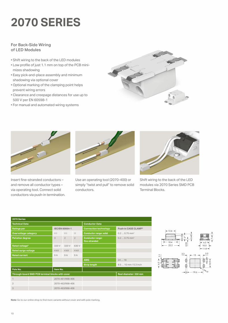
2070 SERIES
Insert fine-stranded conductors – and remove all conductor types – via operating tool. Connect solid conductors via push-in termination.
Use an operating tool (2070-400) or simply “twist and pull” to remove solid conductors.
Shift wiring to the back of the LED modules via 2070 Series SMD PCB Terminal Blocks.
• Shift wiring to the back of the LED modules • Low profile of just 1.1 mm on top of the PCB mini-
mizes shadowing• Easy pick-and-place assembly and minimum
shadowing via optional cover• Optional marking of the clamping point helps
prevent wiring errors• Clearance and creepage distances for use up to
500 V per EN 60598-1• For manual and automated wiring systems
For Back-Side Wiring of LED Modules
10
<__>3
3.9
<_____________________________________>
<____________________________>
<______>
<___>
<______________>
<_______>
<______________________>
15.7
10.85
Pick-and-place surface
min
. 4
min. 3.2
14.05
4.6 7.9
4.7
0.37
2.2
9.5
244.
6
17.2
8
0.3
R
R = Feed direction
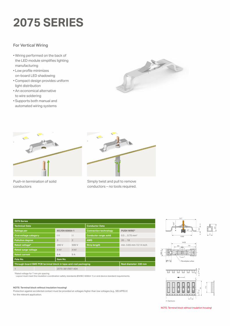
Push-in termination of solid conductors
Simply twist and pull to remove conductors – no tools required.
NOTE: Terminal block without insulation housing!
2075 Series
Technical Data Conductor Data
Ratings per IEC/EN 60664-1 Connection technology PUSH WIRE®
Overvoltage category I I I I I Conductor range: solid 0.5 ... 0.75 mm2
Pollution degree 3 2 AWG 20 … 18
Rated voltage* 200 V 500 V Strip length min. 3.65 mm / 0.14 inch
Rated surge voltage 4 kV 4 kV
Rated current 9 A 9 A
Pole No. Item No.
Through-board SMD PCB terminal block in tape-and-reel packaging Reel diameter: 330 mm
1 2075-381/997-404
*Rated voltage for 7 mm pin spacing Layout must meet the insulation coordination safety standards (EN/IEC 60664-1) or end device standard requirements.
NOTE: Terminal block without insulation housing!Protection against accidental contact must be provided at voltages higher than low voltages (e.g., SELV/PELV) for the relevant application.
For Vertical Wiring
• Wiring performed on the back of the LED module simplifies lighting manufacturing
• Low profile minimizes on-board LED shadowing
• Compact design provides uniform light distribution
• An economical alternative to wire soldering
• Supports both manual and automated wiring systems
2075 SERIES
0888
-015
8/01
05-6
901
– SM
D F
AMIL
IY B
ROCH
URE
1.6
US –
02/
2018
-00
– Pr
inte
d in
Ger
man
y –
Subj
ect t
o de
sign
cha
nges
WAGO Kontakttechnik GmbH & Co. KGPostfach 2880 · 32385 MindenHansastraße 27 · 32423 [email protected]
Headquarters +49 (0)571/ 887 - 0Sales +49 (0)571/ 887 - 222Order service +49 (0)571/ 887 - 44 333Fax +49 (0)571/ 887 - 8 44 169
WAGO is a registered trademark of WAGO Verwaltungsgesellschaft mbH.“Copyright – WAGO Kontakttechnik GmbH & Co. KG – All rights reserved. The content and structure of the WAGO websites, catalogs, videos and other WAGO media are subject to copy-right. Distribution or modification to the contents of these pages and videos is prohibited. Furthermore, the content may neither be copied nor made available to third parties for commer-cial purposes. Also subject to copyright are the images and videos that were made available to WAGO Kontakttechnik GmbH & Co. KG by third parties.”


![Courtesy of Steven Engineering, Inc. - 230 Ryan Way, South ... · 2 x 0.5 mm2 403 PTDA series ... Rated surge voltage [kV] 2.5 2.5 2.5 2.5 2.5 2.5 Approval data (UL/CUL) Use Group](https://img.pdfslide.us/doc/110x75/5c78029809d3f21d538c775a/courtesy-of-steven-engineering-inc-230-ryan-way-south-2-x-05-mm2-403.jpg)