Embed Size (px)
Citation preview
1
Copyright Information furnished by SMC Networks, Inc. (SMC) is believed to be accurate and reliable. However, no responsibility is assumed by SMC for its use, nor for any infringements of patents or other rights of third parties which may result from its use. No license is granted by implication or otherwise under any patent or patent rights of SMC. SMC reserves the right to change specifications at any time without notice.
Copyright © 2005 by SMC Networks, Inc.
38 Tesla Irvine, CA 92618
All rights reserved.
Trademarks: SMC is a registered trademark; and EZ Card, is a trademark of SMC Networks, Inc. Other product and company names are trademarks or registered trademarks of their respective holders.

2
Contents Warranty …………………………………………………….………………...... 3 Compliances ……………………………..……………………………………. 5 Introduction/ Hardware Description .....................................................….. 7 Package Contents ………………………………………………………….… 8 Hardware Installation ……….……………………………………….………. 9 Driver Installation …………………………………………..………………... 10 Windows 9x ………..………….……………………….……………….….… 11 Windows ME ……….……………….……………………………….………. 15 Windows NT ……….………………….…………………………….……….. 17 Windows 2000 ………...…………………….…………………….….……… 18 Windows XP ……………………………………….………..……………….. 20 Driver Verification ……………………..……………………………………. 27 Troubleshooting ……………….……………………………………………. 31 Cable Types and Specifications ……………..…………….……………… 33 Technical Specifications ...………………………………………………..… 34 Terminology …….………………………………………………..……….…… 35
3
Limited Warranty
Limited Warranty Statement: SMC Networks, Inc. (“SMC”) warrants its products to be free from defects in workmanship and materials, under normal use and service, for the applicable warranty term. All SMC products carry a standard 90-day limited warranty from the date of purchase from SMC or its Authorized Reseller. SMC may, at its own discretion, repair or replace any product not operating as warranted with a similar or functionally equivalent product, during the applicable warranty term. SMC will endeavor to repair or replace any product returned under warranty within 30 days of receipt of the product.
The standard limited warranty can be upgraded to a Limited Lifetime* warranty by registering new products within 30 days of purchase from SMC or its Authorized Reseller. Registration can be accomplished via the enclosed product registration card or online via the SMC web site. Failure to register will not affect the standard limited warranty. The Limited Lifetime warranty covers a product during the Life of that Product, which is defined as the period of time during which the product is an ‘Active’ SMC product. A product is considered to be ‘Active’ while it is listed on the current SMC price list. As new technologies emerge, older technologies become obsolete and SMC will, at its discretion, replace an older product in its product line with one that incorporates these newer technologies. At that point, the obsolete product is discontinued and is no longer an ‘Active’ SMC product. A list of discontinued products with their respective dates of discontinuance can be found at http://www.smc.com/smc/pages_html/support.html.
All products that are replaced become the property of SMC. Replacement products may be either new or reconditioned. Any replaced or repaired product carries either a 30-day limited warranty or the remainder of the initial warranty, whichever is longer. SMC is not responsible for any custom software or firmware, configuration information, or memory data of Customer contained in, stored on, or integrated with any products returned to SMC pursuant to any warranty. Products returned to SMC should have any customer-installed accessory or add-on components, such as expansion modules, removed prior to returning the product for replacement. SMC is not responsible for these items if they are returned with the product.
Customers must contact SMC for a Return Material Authorization number prior to returning any product to SMC. Proof of purchase may be required. Any product returned to SMC without a valid Return Material Authorization (RMA) number clearly marked on the outside of the package will be returned to customer at customer’s expense. For warranty claims within North America, please call our toll-free customer support number at (800) 762-4968. Customers are responsible for all shipping charges from their facility to SMC. SMC is responsible for return shipping charges from SMC to customer.

4
Limited Warranty
WARRANTIES EXCLUSIVE: IF AN SMC PRODUCT DOES NOT OPERATE AS WARRANTED ABOVE, CUSTOMER’S SOLE REMEDY SHALL BE REPAIR OR REPLACEMENT OF THE PRODUCT IN QUESTION, AT SMC’S OPTION. THE FOREGOING WARRANTIES AND REMEDIES ARE EXCLUSIVE AND ARE IN LIEU OF ALL OTHER WARRANTIES OR CONDITIONS, EXPRESS OR IMPLIED, EITHER IN FACT OR BY OPERATION OF LAW, STATUTORY OR OTHERWISE, INCLUDING WARRANTIES OR CONDITIONS OF MERCHANTABILITY AND FITNESS FOR A PARTICULAR PURPOSE. SMC NEITHER ASSUMES NOR AUTHORIZES ANY OTHER PERSON TO ASSUME FOR IT ANY OTHER LIABILITY IN CONNECTION WITH THE SALE, INSTALLATION, MAINTENANCE OR USE OF ITS PRODUCTS. SMC SHALL NOT BE LIABLE UNDER THIS WARRANTY IF ITS TESTING AND EXAMINATION DISCLOSE THE ALLEGED DEFECT IN THE PRODUCT DOES NOT EXIST OR WAS CAUSED BY CUSTOMER’S OR ANY THIRD PERSON’S MISUSE, NEGLECT, IMPROPER INSTALLATION OR TESTING, UNAUTHORIZED ATTEMPTS TO REPAIR, OR ANY OTHER CAUSE BEYOND THE RANGE OF THE INTENDED USE, OR BY ACCIDENT, FIRE, LIGHTNING, OR OTHER HAZARD.
LIMITATION OF LIABILITY: IN NO EVENT, WHETHER BASED IN CONTRACT OR TORT (INCLUDING NEGLIGENCE), SHALL SMC BE LIABLE FOR INCIDENTAL, CONSEQUENTIAL, INDIRECT, SPECIAL, OR PUNITIVE DAMAGES OF ANY KIND, OR FOR LOSS OF REVENUE, LOSS OF BUSINESS, OR OTHER FINANCIAL LOSS ARISING OUT OF OR IN CONNECTION WITH THE SALE, INSTALLATION, MAINTENANCE, USE, PERFORMANCE, FAILURE, OR INTERRUPTION OF ITS PRODUCTS, EVEN IF SMC OR ITS AUTHORIZED RESELLER HAS BEEN ADVISED OF THE POSSIBILITY OF SUCH DAMAGES.
SOME STATES DO NOT ALLOW THE EXCLUSION OF IMPLIED WARRANTIES OR THE LIMITATION OF INCIDENTAL OR CONSEQUENTIAL DAMAGES FOR CONSUMER PRODUCTS, SO THE ABOVE LIMITATIONS AND EXCLUSIONS MAY NOT APPLY TO YOU. THIS WARRANTY GIVES YOU SPECIFIC LEGAL RIGHTS, WHICH MAY VARY FROM STATE TO STATE. NOTHING IN THIS WARRANTY SHALL BE TAKEN TO AFFECT YOUR STATUTORY RIGHTS.*
SMC will provide warranty service for one year following discontinuance from the active SMC price list. Under the limited lifetime warranty, internal and external power supplies, fans, and cables are covered by a standard one-year warranty from date of purchase.
5
Compliances
FCC - Class B
This equipment has been tested and found to comply with the limits for a Class B digital device, pursuant to Part 15 of the FCC Rules. These limits are designed to provide reasonable protection against harmful interference in a residential installation. This equipment generates, uses, and can radiate radio frequency energy and, if not installed and used in accordance with instructions, may cause harmful interference to radio communications. However, there is no guarantee that the interference will not occur in a particular installation. If this equipment does cause harmful interference to radio or television reception, which can be determined by turning the equipment off and on, the user is encouraged to try to correct the interference by one or more of the following measures:
• Reorient the receiving antenna • Increase the separation between the equipment and receiver • Connect the equipment into an outlet on a circuit different from that to which the receiver is
connected • Consult the dealer or an experienced radio/TV technician for help
EC Conformance Declaration - Class B
SMC contact for these products in Europe is: SMC Networks Europe, Edificio Conata II, Calle Fructuós Gelabert 6-8, 2o, 4a, 08970 - Sant Joan Despí, Barcelona, Spain.
This information technology equipment complies with the requirements of the Council Directive 89/336/EEC on the Approximation of the laws of the Member States relating to Electromagnetic Compatibility and 73/23/EEC for electrical equipment used within certain voltage limits and the Amendment Directive 93/68/EEC. For the evaluation of the compliance with these Directives, the following standards were applied:
RFI Emission:
• Limit class B according to EN55022:1998 • Limit class B for harmonic current emission according to EN61000-3-2/1995 • Limitation of voltage fluctuation and flicker in low-voltage supply system according to
EN61000-3-3/1995 Immunity:
• Product family standard according to EN55024:1998 • Electrostatic Discharge according to EN61000-4-2:1995 (Contact Discharge: ±4 kV, Air
Discharge: ±8 kV) • Radio-frequency electromagnetic field according to EN61000-4-3:1996 (80 - 1000 MHz with
1 kHz AM 80% Modulation: 3 V/m) • Electrical fast transient/burst according to EN61000-4-4:1995 (AC/DC power supply: ±1 kV,
Data/Signal lines: ±0.5 kV) • Surge immunity test according to EN61000-4-5:1995 (AC/DC Line to Line: ±1 kV, AC/DC
Line to Earth: ±2 kV)

6
• Immunity to conducted disturbances, Induced by radio-frequency fields: EN61000-4-6:1996 (0.15 - 80 MHz with 1 kHz AM 80% Modulation: 3 V/m)
• Power frequency magnetic field immunity test according to EN61000-4-8:1993 (1 A/m at frequency 50 Hz)
• Voltage dips, short interruptions and voltage variations immunity test according to EN61000-4-11:1994 (>95% Reduction @10 ms, 30% Reduction @500 ms, >95% Reduction @5000 ms)
LVD: • EN60950 (A1/1992; A2/1993; A3/1993; A4/1995; A11/1997)
Warning: Do not plug a phone jack connector in the RJ-45 port. This may damage this device. Les raccordeurs ne sont pas utilisé pour le systéme téléphonique!
Industry Canada - Class B
This digital apparatus does not exceed the Class B limits for radio noise emissions from digital apparatus as set out in the interference-causing equipment standard entitled “Digital Apparatus,” ICES-003 of the Department of Communications.
Cet appareil numérique respecte les limites de bruits radioélectriques applicables aux appareils numériques de Classe B prescrites dans la norme sur le matériel brouilleur: “Appareils Numériques,” NMB-003 édictée par le ministère des Communications.
Japan VCCI Class B
Australia AS/NZS 3548 (1995) - Class B
7
Introduction
SMC’s EZ PCI Card 10/100 is a dual-speed Fast Ethernet card for PCI local bus-compliant computers. A true plug-and-play device, this card is auto-configurable upon power up and also supports auto-negotiation to automatically select the optimum speed and communication mode of an attached device. This EZ PCI Card 10/100 complies with ACPI and OnNow PC98/ PC99 and also supports Remote LAN Wakeup for remote management. Software can be loaded and updated, configurations changed, data backed up and inventory checked, all from a central location. See “Remote LAN Wakeup” on page 5 for more information.
Features and Benefits
• Compatible with IEEE 802.3 Ethernet and IEEE 802.3u Fast Ethernet standards • Full- and half-duplex support for both 10 Mbps and 100 Mbps speeds • Auto-negotiation selects 10/100 Mbps and full/half duplex automatically • Supports full-duplex operation for up to 200 Mbps of bandwidth • Automatic configuration set up using the PCI computer’s BIOS setup program • Supports Remote LAN Wakeup for efficient centralized desktop management • Supports optional boot ROM for remote booting of a management PC’s operating system • ACPI and OnNow/PC98/99 compliance reduces power consumption
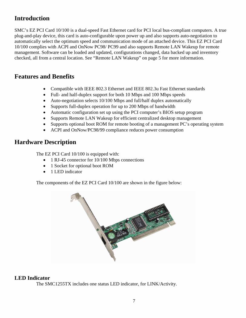
Hardware Description
The EZ PCI Card 10/100 is equipped with:
• 1 RJ-45 connector for 10/100 Mbps connections • 1 Socket for optional boot ROM • 1 LED indicator
The components of the EZ PCI Card 10/100 are shown in the figure below:
LED Indicator The SMC1255TX includes one status LED indicator, for LINK/Activity.
8
Remote LAN Wakeup
Remote LAN Wakeup capability is a key feature of a centrally managed PC environment. This technology enables networked PCs to be “woken up” from a sleep or powered-off state so they can be managed from a central location, at any time of the day or night.
To employ Remote LAN Wakeup, three elements are required:
• Desktop management software that can send a “wake-up” packet to a PC. • A Wake-On-LAN enabled PC motherboard that can supply low-level auxiliary power to a
network card when the PC is powered off. • A Wake-On-LAN network card that can recognize a wake-up packet and signal the PC to power up.
A Wake-On-LAN enabled PC is never completely powered off. It maintains a low-level auxiliary power supply to the motherboard. Even if the PC is powered off, the network card is always active and monitoring the network. When a wake-up packet is detected, the card signals the motherboard to power up the PC. With the PC powered on, maintenance and other support tasks can be performed.
Equipment Checklist
After unpacking the EZ PCI 10/100 card, check the contents of the box to be sure you have received the following components:
• EZ PCI 10/100 card SMC1255TX-1 • Quick Install Guide • Drivers and Documentation CD • SMC Warranty Registration Card
Immediately inform your dealer in the event of any incorrect, missing or damaged parts. If possible, please retain the carton and original packing materials in case there is a need to return the product.
Please fill out and return the Warranty Registration Card to SMC or register on SMC’s Web site. The EZ PCI Card 10/100 is covered by a limited lifetime warranty.

9
Hardware Installation Warnings:
• Network cards are sensitive to static electricity. To protect the card, avoid touching its electrical components and always touch the metal chassis of your computer before handling the card.
1. Switch off the computer, unplug the power cord, and remove the computer’s cover. 2. Select an unused PCI bus-master slot and remove its protective bracket. 3. Carefully insert the card and press until all the edge connectors are firmly seated inside
the slot. Then screw the card’s bracket securely into the PC’s chassis. 4. Connect the EZ PCI Card 10/100 directly to a 10BASE-T or 100BASE-TX hub or switch
using UTP cable (Category 3, 4 or 5 for 10BASE-T; Category 5 for 100BASE-TX). The maximum allowable length of UTP cable connections is 100 meters (328 ft). When inserting an RJ-45 plug, be sure the tab on the plug clicks into position to ensure that it is properly seated.
5. Replace the computer’s cover and power it on. The EZ PCI Card 10/100 should be automatically configured by the host computer’s BIOS. However, if you have an older computer, you may have to manually configure the computer’s BIOS settings. See “Troubleshooting” on page 10.
6. The driver & Documentation that accompanies the EZ Card 10/100 contains all the network operating system drivers supported by this card. Please read the “RELEASE.TXT” file on the CD for a list of all drivers. Refer to this guide for instructions on installing drivers. Any new or updated drivers can be downloaded from SMC’s Web site (see the back cover of this guide).
10
Driver Installation
Windows 95/98/Me/NT/2000/XP
NOTE: Installation processes will require the use of your original, licensed copy of Windows. Please have your Windows CD available BEFORE proceeding with the installation.
Setup Processes
The following are Operating System-specific options that may appear during this installation procedure:
Windows 95/98: If you are using Windows 95 or 98, you must have your original Windows CD on hand. The system will request it near the end of the installation process.
Windows Me: The installation process is fully Plug-and-Play. You will be asked to reboot when the process is complete.
Windows NT: This is NOT a Plug-and-Play operating system. As a result, you need to manually add the adapter to your network properties. (See Section 5 for further details)
Windows 2000/XP: Select [Install the software automatically] if prompted and click [Next] to complete the installation.
11
Windows 9x
NOTE: Installation processes will require the use of your original, licensed copy of Windows. Please have your Windows CD available BEFORE proceeding with the installation.
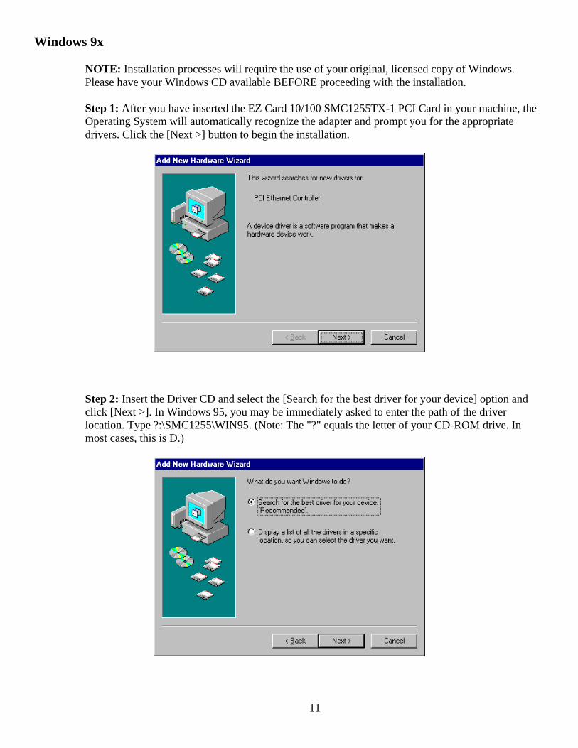
Step 1: After you have inserted the EZ Card 10/100 SMC1255TX-1 PCI Card in your machine, the Operating System will automatically recognize the adapter and prompt you for the appropriate drivers. Click the [Next >] button to begin the installation.
Step 2: Insert the Driver CD and select the [Search for the best driver for your device] option and click [Next >]. In Windows 95, you may be immediately asked to enter the path of the driver location. Type ?:\SMC1255\WIN95. (Note: The "?" equals the letter of your CD-ROM drive. In most cases, this is D.)
12
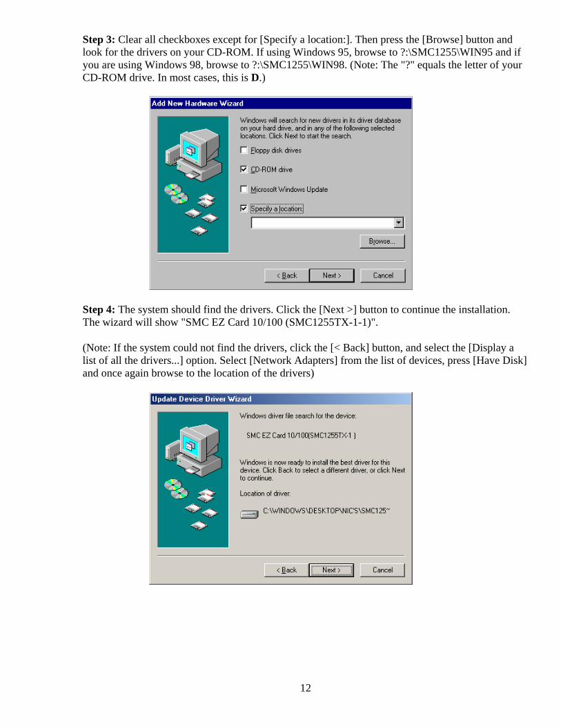
Step 3: Clear all checkboxes except for [Specify a location:]. Then press the [Browse] button and look for the drivers on your CD-ROM. If using Windows 95, browse to ?:\SMC1255\WIN95 and if you are using Windows 98, browse to ?:\SMC1255\WIN98. (Note: The "?" equals the letter of your CD-ROM drive. In most cases, this is D.)
Step 4: The system should find the drivers. Click the [Next >] button to continue the installation. The wizard will show "SMC EZ Card 10/100 (SMC1255TX-1-1)".
(Note: If the system could not find the drivers, click the [< Back] button, and select the [Display a list of all the drivers...] option. Select [Network Adapters] from the list of devices, press [Have Disk] and once again browse to the location of the drivers)
13
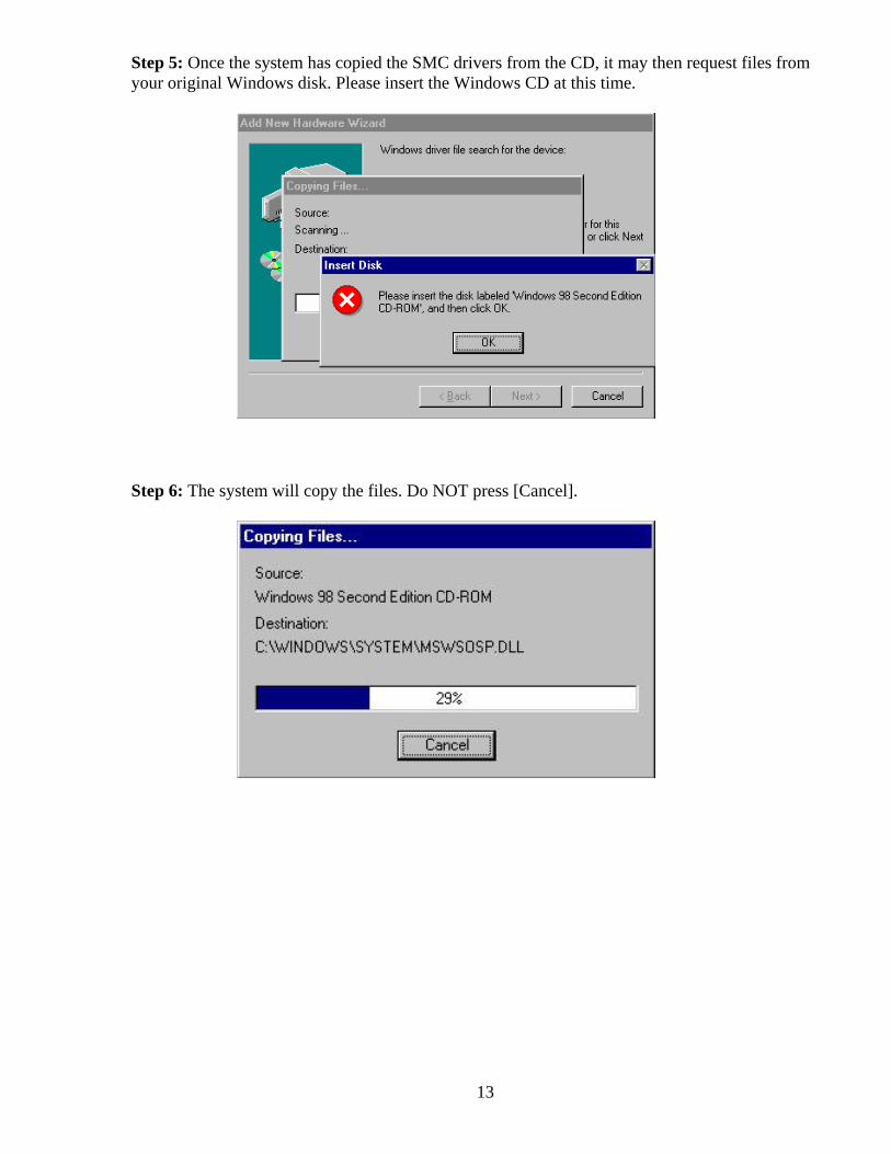
Step 5: Once the system has copied the SMC drivers from the CD, it may then request files from your original Windows disk. Please insert the Windows CD at this time.
Step 6: The system will copy the files. Do NOT press [Cancel].
14
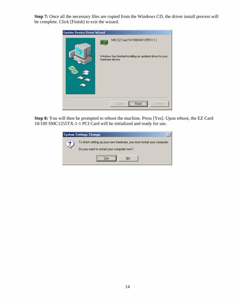
Step 7: Once all the necessary files are copied from the Windows CD, the driver install process will be complete. Click [Finish] to exit the wizard.
Step 8: You will then be prompted to reboot the machine. Press [Yes]. Upon reboot, the EZ Card 10/100 SMC1255TX-1-1 PCI Card will be initialized and ready for use.
15
Windows Me
NOTE: Installation processes will require the use of your original, licensed copy of Windows. Please have your Windows CD available BEFORE proceeding with the installation.
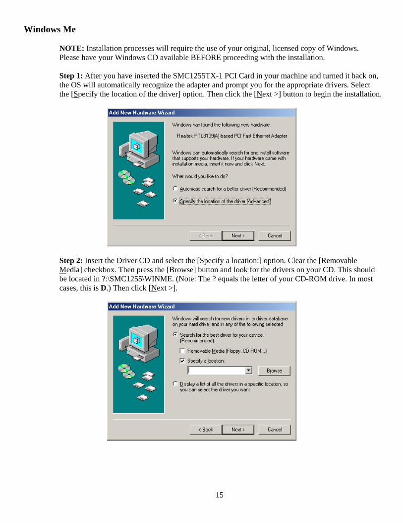
Step 1: After you have inserted the SMC1255TX-1 PCI Card in your machine and turned it back on, the OS will automatically recognize the adapter and prompt you for the appropriate drivers. Select the [Specify the location of the driver] option. Then click the [Next >] button to begin the installation.
Step 2: Insert the Driver CD and select the [Specify a location:] option. Clear the [Removable Media] checkbox. Then press the [Browse] button and look for the drivers on your CD. This should be located in ?:\SMC1255\WINME. (Note: The ? equals the letter of your CD-ROM drive. In most cases, this is D.) Then click [Next >].
16
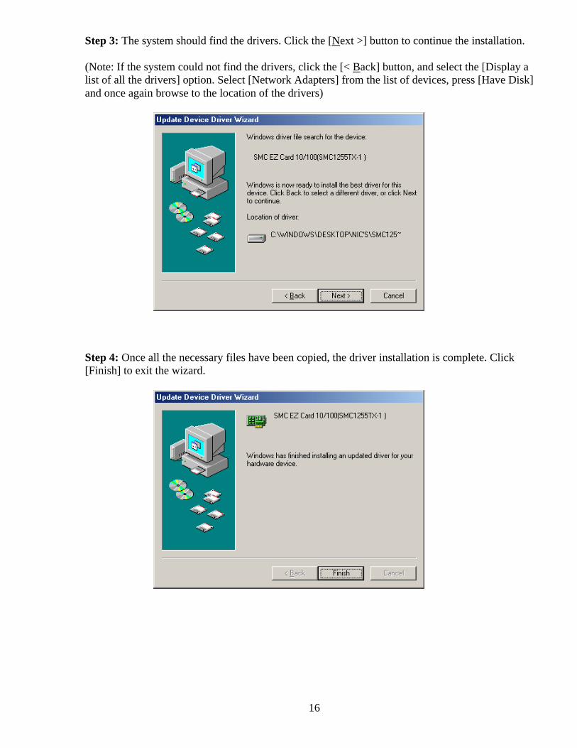
Step 3: The system should find the drivers. Click the [Next >] button to continue the installation.
(Note: If the system could not find the drivers, click the [< Back] button, and select the [Display a list of all the drivers] option. Select [Network Adapters] from the list of devices, press [Have Disk] and once again browse to the location of the drivers)
Step 4: Once all the necessary files have been copied, the driver installation is complete. Click [Finish] to exit the wizard.
17
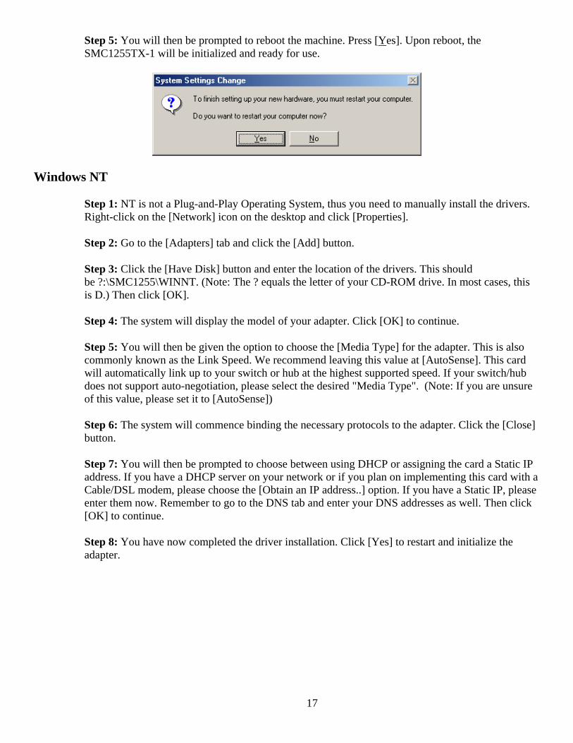
Step 5: You will then be prompted to reboot the machine. Press [Yes]. Upon reboot, the SMC1255TX-1 will be initialized and ready for use.
Windows NT
Step 1: NT is not a Plug-and-Play Operating System, thus you need to manually install the drivers. Right-click on the [Network] icon on the desktop and click [Properties].
Step 2: Go to the [Adapters] tab and click the [Add] button.
Step 3: Click the [Have Disk] button and enter the location of the drivers. This should be ?:\SMC1255\WINNT. (Note: The ? equals the letter of your CD-ROM drive. In most cases, this is D.) Then click [OK].
Step 4: The system will display the model of your adapter. Click [OK] to continue.
Step 5: You will then be given the option to choose the [Media Type] for the adapter. This is also commonly known as the Link Speed. We recommend leaving this value at [AutoSense]. This card will automatically link up to your switch or hub at the highest supported speed. If your switch/hub does not support auto-negotiation, please select the desired "Media Type". (Note: If you are unsure of this value, please set it to [AutoSense])
Step 6: The system will commence binding the necessary protocols to the adapter. Click the [Close] button.
Step 7: You will then be prompted to choose between using DHCP or assigning the card a Static IP address. If you have a DHCP server on your network or if you plan on implementing this card with a Cable/DSL modem, please choose the [Obtain an IP address..] option. If you have a Static IP, please enter them now. Remember to go to the DNS tab and enter your DNS addresses as well. Then click [OK] to continue.
Step 8: You have now completed the driver installation. Click [Yes] to restart and initialize the adapter.
18
Windows 2000
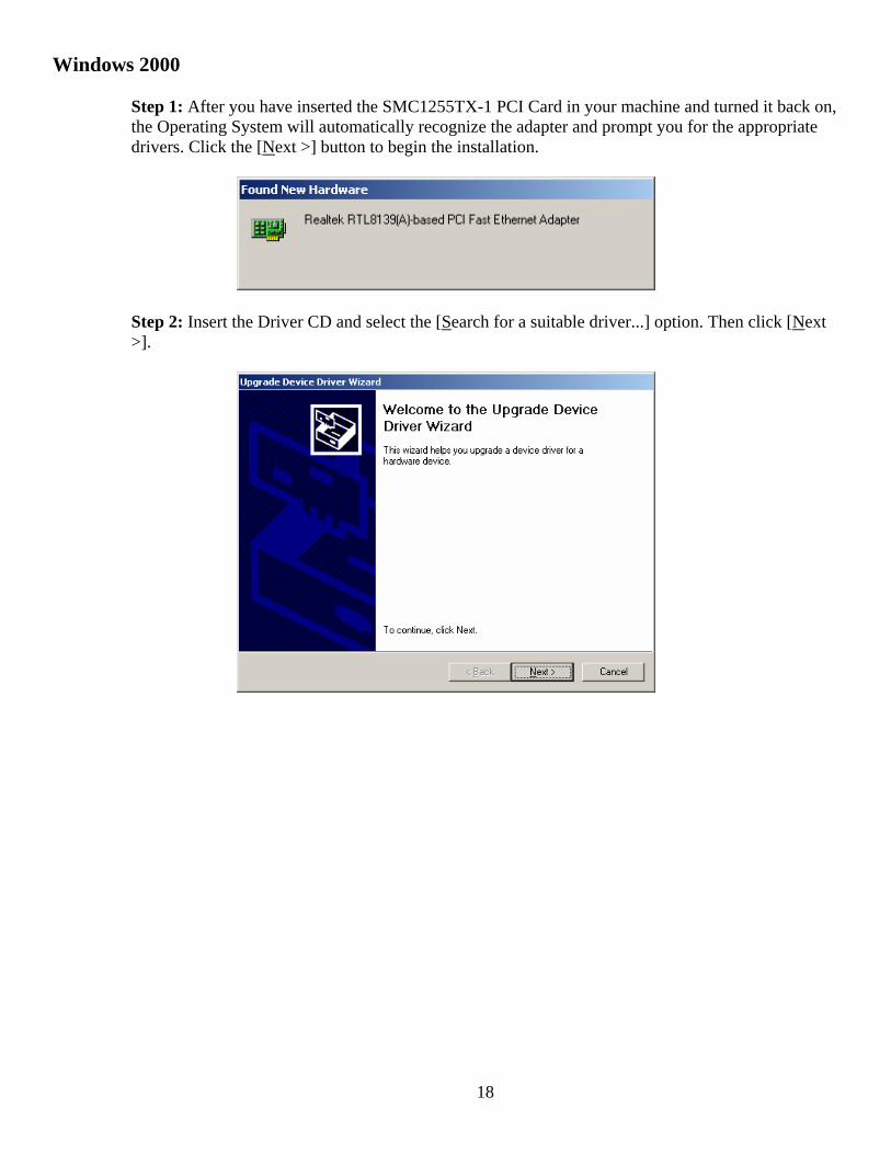
Step 1: After you have inserted the SMC1255TX-1 PCI Card in your machine and turned it back on, the Operating System will automatically recognize the adapter and prompt you for the appropriate drivers. Click the [Next >] button to begin the installation.
Step 2: Insert the Driver CD and select the [Search for a suitable driver...] option. Then click [Next >].
19
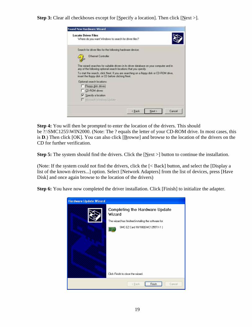
Step 3: Clear all checkboxes except for [Specify a location]. Then click [Next >].
Step 4: You will then be prompted to enter the location of the drivers. This should be ?:\SMC1255\WIN2000. (Note: The ? equals the letter of your CD-ROM drive. In most cases, this is D.) Then click [OK]. You can also click [Browse] and browse to the location of the drivers on the CD for further verification.
Step 5: The system should find the drivers. Click the [Next >] button to continue the installation.
(Note: If the system could not find the drivers, click the [< Back] button, and select the [Display a list of the known drivers...] option. Select [Network Adapters] from the list of devices, press [Have Disk] and once again browse to the location of the drivers)
Step 6: You have now completed the driver installation. Click [Finish] to initialize the adapter.
20
Windows XP
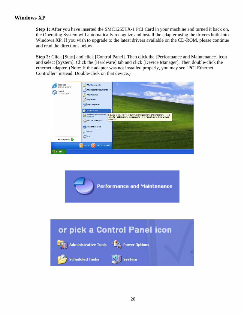
Step 1: After you have inserted the SMC1255TX-1 PCI Card in your machine and turned it back on, the Operating System will automatically recognize and install the adapter using the drivers built-into Windows XP. If you wish to upgrade to the latest drivers available on the CD-ROM, please continue and read the directions below.
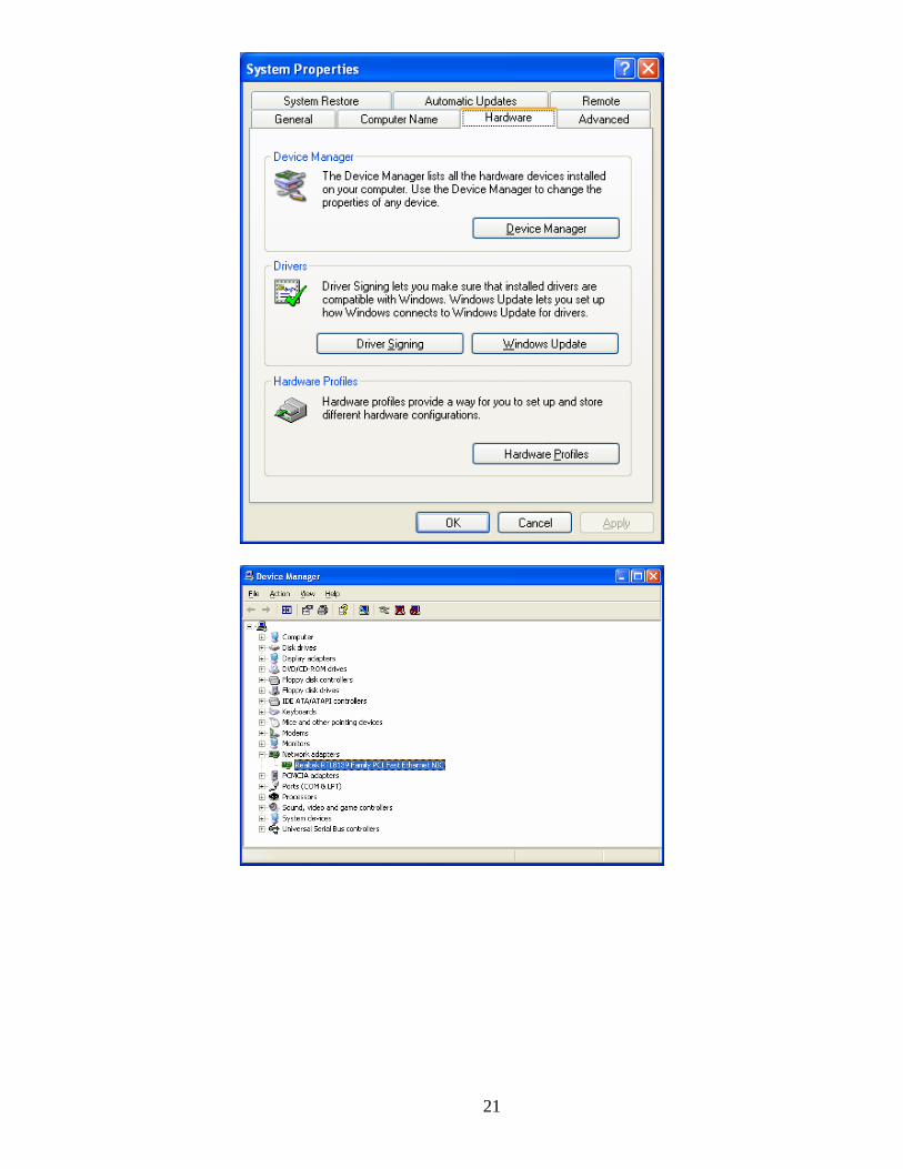
Step 2: Click [Start] and click [Control Panel]. Then click the [Performance and Maintenance] icon and select [System]. Click the [Hardware] tab and click [Device Manager]. Then double-click the ethernet adapter. (Note: If the adapter was not installed properly, you may see "PCI Ethernet Controller" instead. Double-click on that device.)
21
22
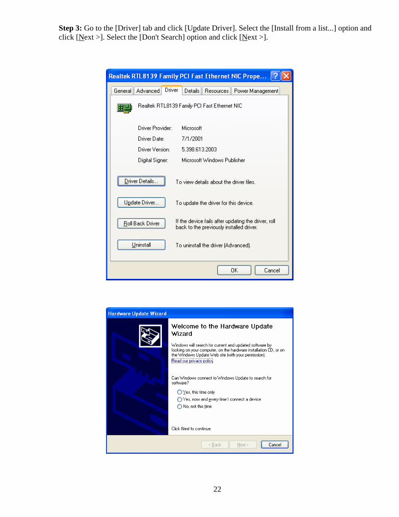
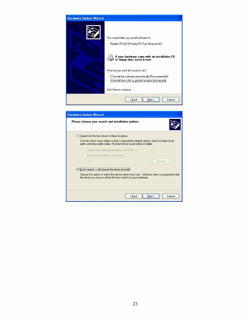
Step 3: Go to the [Driver] tab and click [Update Driver]. Select the [Install from a list...] option and click [Next >]. Select the [Don't Search] option and click [Next >].
23
24
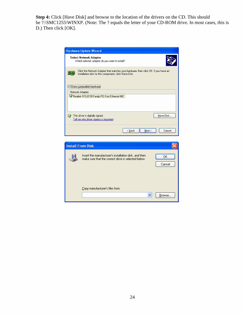
Step 4: Click [Have Disk] and browse to the location of the drivers on the CD. This should be ?:\SMC1255\WINXP. (Note: The ? equals the letter of your CD-ROM drive. In most cases, this is D.) Then click [OK].
25
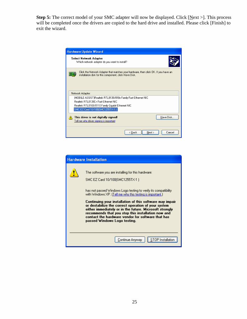
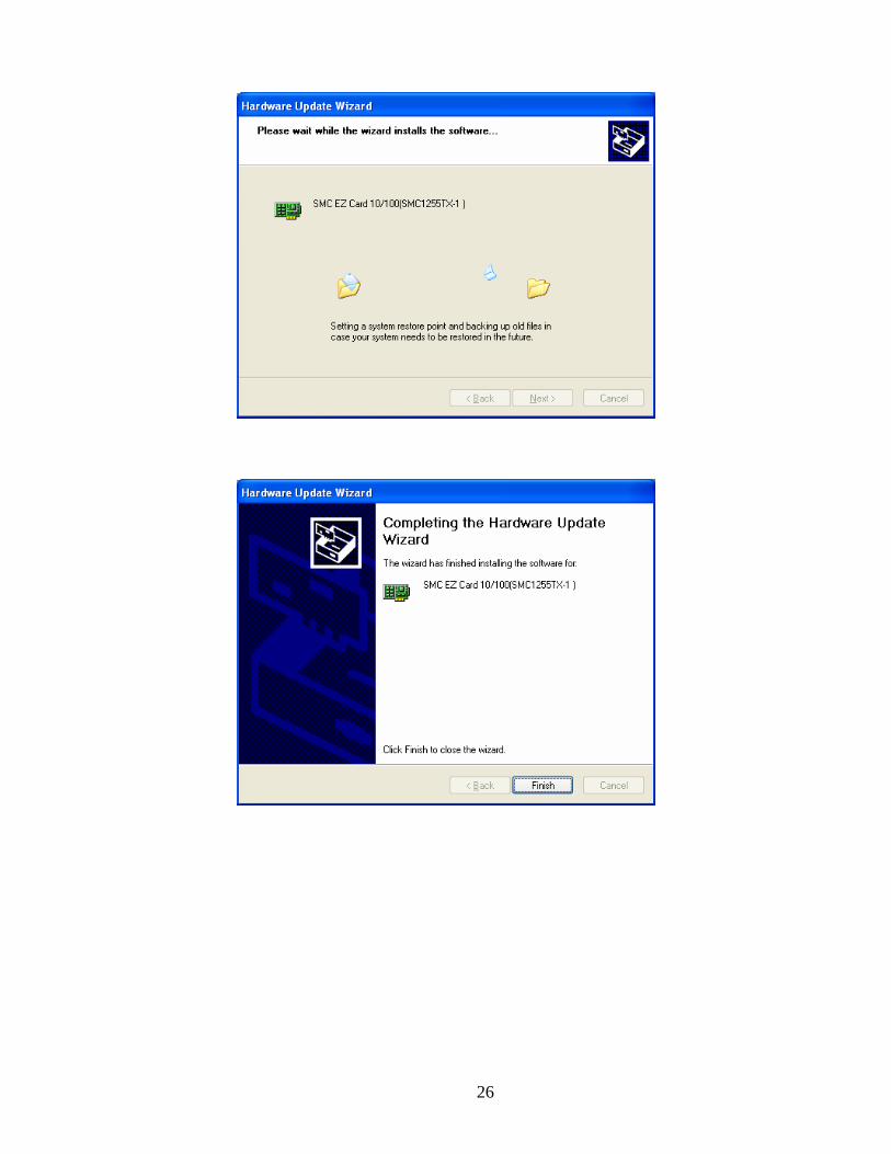
Step 5: The correct model of your SMC adapter will now be displayed. Click [Next >]. This process will be completed once the drivers are copied to the hard drive and installed. Please click [Finish] to exit the wizard.
26
27
Driver Verification
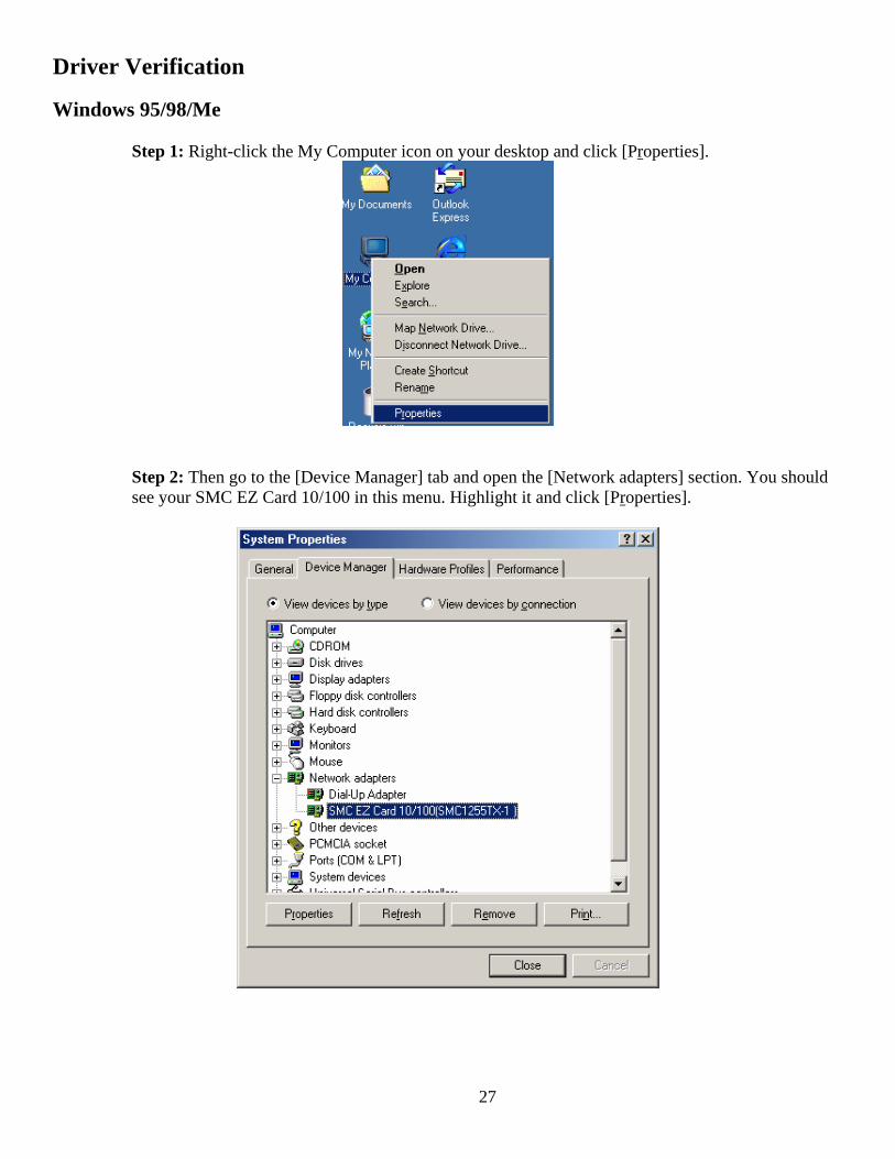
Windows 95/98/Me Step 1: Right-click the My Computer icon on your desktop and click [Properties].
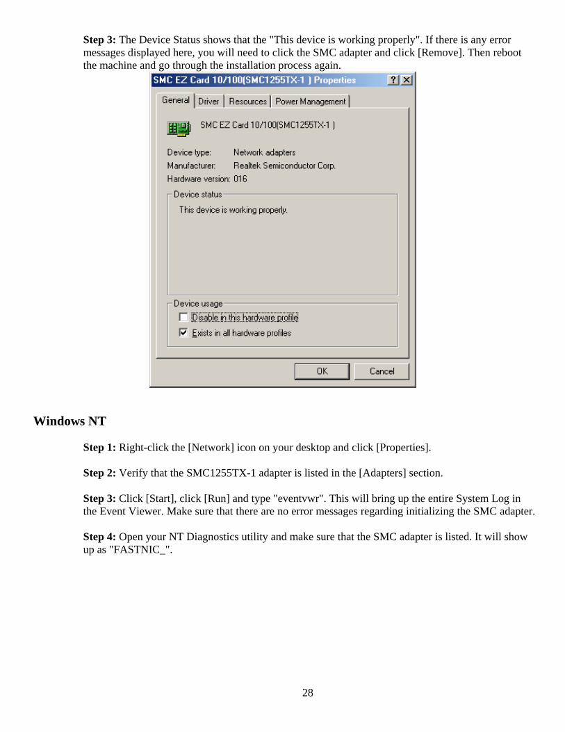
Step 2: Then go to the [Device Manager] tab and open the [Network adapters] section. You should see your SMC EZ Card 10/100 in this menu. Highlight it and click [Properties].
28
Step 3: The Device Status shows that the "This device is working properly". If there is any error messages displayed here, you will need to click the SMC adapter and click [Remove]. Then reboot the machine and go through the installation process again.
Windows NT Step 1: Right-click the [Network] icon on your desktop and click [Properties]. Step 2: Verify that the SMC1255TX-1 adapter is listed in the [Adapters] section. Step 3: Click [Start], click [Run] and type "eventvwr". This will bring up the entire System Log in the Event Viewer. Make sure that there are no error messages regarding initializing the SMC adapter. Step 4: Open your NT Diagnostics utility and make sure that the SMC adapter is listed. It will show up as "FASTNIC_".
29
Windows 2000
Step 1: Right-click the My Computer icon on your desktop and click [Properties]. Step 2: Then go to the Hardware tab and click [Device Manager]. Open the [Network adapters] section. You should see your SMC EZ Card 10/100 card in this menu. Right-click your adapter and click [Properties]. Step 3: The Device Status shows that the "This device is working properly". If there are any error messages displayed here, you will need to right-click the SMC adapter and click [Uninstall]. Then reboot the machine and go through the installation process again.
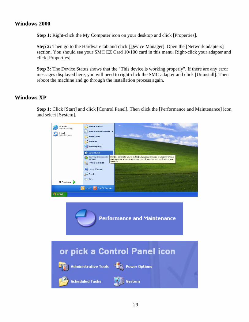
Windows XP Step 1: Click [Start] and click [Control Panel]. Then click the [Performance and Maintenance] icon and select [System].
30
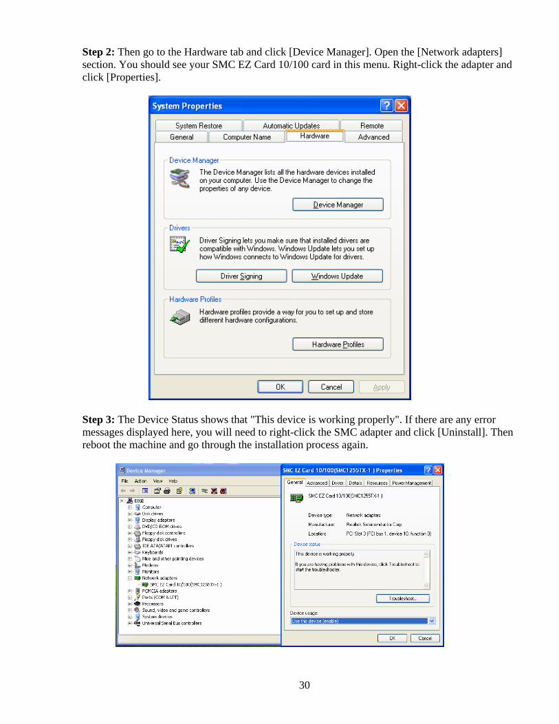
Step 2: Then go to the Hardware tab and click [Device Manager]. Open the [Network adapters] section. You should see your SMC EZ Card 10/100 card in this menu. Right-click the adapter and click [Properties].
Step 3: The Device Status shows that "This device is working properly". If there are any error messages displayed here, you will need to right-click the SMC adapter and click [Uninstall]. Then reboot the machine and go through the installation process again.
31
TROUBLESHOOTING
PCI Compatibility
• Early PCI BIOS versions do not properly support the new PCI specifications and may “hang” when a network card driver tries to load. If this occurs, make sure your BIOS correctly supports the PCI Local Bus Specification (v2.0 or later) and upgrade your computer BIOS to the latest version
• Some PCI computers are not self-configuring and require you to perform some or all of the following functions by motherboard jumper changes and/or BIOS Setup configuration:
o Verify that the PCI slot is an enabled bus-master slot and not a slave PCI slot. The SMC1255TX-1 must be installed in a PCI bus-master slot. In some computers the PCI slot must be configured to enable bus mastering. Refer to your PC’s manual and check the PCI BIOS Setup program to be sure the PCI slot is an enabled bus-master slot.
o In some computers, you may be required to disable Plug-and-Play in the BIOS Setup program if resources are not properly assigned between the network card and other installed cards.
o Some computers may require you to reserve interrupts and memory addresses for installed ISA cards to prevent PCI cards from using the same settings. Refer to your PC’s manual and check the PCI BIOS Setup program configuration options for ISA cards.
o Make sure the PCI slot is configured to support INTA. o Ensure that INTA for the slot is assigned to a free interrupt (IRQ) number.
Common Installation Problems
Problems are often caused by cabling errors, conflicts with other devices installed in the same computer, or software that has been configured incorrectly. If you encounter a problem with the SMC1255TX-1, use the following checklists to identify and correct the problem.
• If you’re computer cannot find the SMC1255TX-1, or the network driver does not install correctly, check the following items before contacting SMC Technical Support
o Make sure the card is securely seated in the PCI slot. Check for any hardware problems, such as physical damage to the card’s edge connector.
o Try the card in another PCI bus-master slot. If this fails, test the card in a completely different system or try using a second SMC1255TX-1 in that particular bus-master slot.
o Check for resource conflicts in the PCI configuration. o Make sure your computer is using the latest BIOS available. Contact the
manufacturer of the computer or motherboard for information on updating the BIOS (e.g. – Dell, Toshiba, etc)
o If there are other network cards in the computer, they may be causing conflicts. Remove all other cards from the computer and test the SMC1255TX-1 separately. If you continue to have problems, remove all cards except the SMC1255TX-1 and your video card.

32
Network Connection Problems There may be a network connection problem if the LED on the card’s bracket does not light, or if you cannot access any network resources from the computer. Check the following items before contacting SMC Technical Support.
• Be sure you are using Category 5 cable for 100 Mbps connections, and that the length of any cable does not exceed 100 m (328 ft).
• Inspect all network cables and connections. Make sure the network cable is securely attached to the card’s connector.
• Make sure the correct network card driver is installed for your operating system. If necessary, try reinstalling the driver.
• Make sure the computer and other network devices are receiving power. If you suspect a power outlet to be faulty, plug another device into it to verify that it is working.
• If the network card’s speed or duplex mode has been configured manually, check that it matches that of the attached network device port. Note that it is recommended to set the card to auto-negotiation when installing the network driver.
• The port on the network device that the card is attached to may be defective. Try using another port on the device.
• If you cannot access a Windows or NetWare service on the network, check that you have enabled and configured the service correctly. If you cannot connect to a particular server, ensure that you have access rights and a valid ID and password.
• If you cannot access the Internet, be sure you have configured your system for TCP/IP.
33
Cable Types and Specifications
Cable Types and Specifications
Cable Type Max. Length Connector 10BASE-T Cat. 3, 4, 5 100-ohm UTP100 m (328 ft) RJ-45 100BASE-TX Cat. 5 100-ohm UTP100 m (328 ft) RJ-45
Twisted-Pair Cable and Pin Assignments
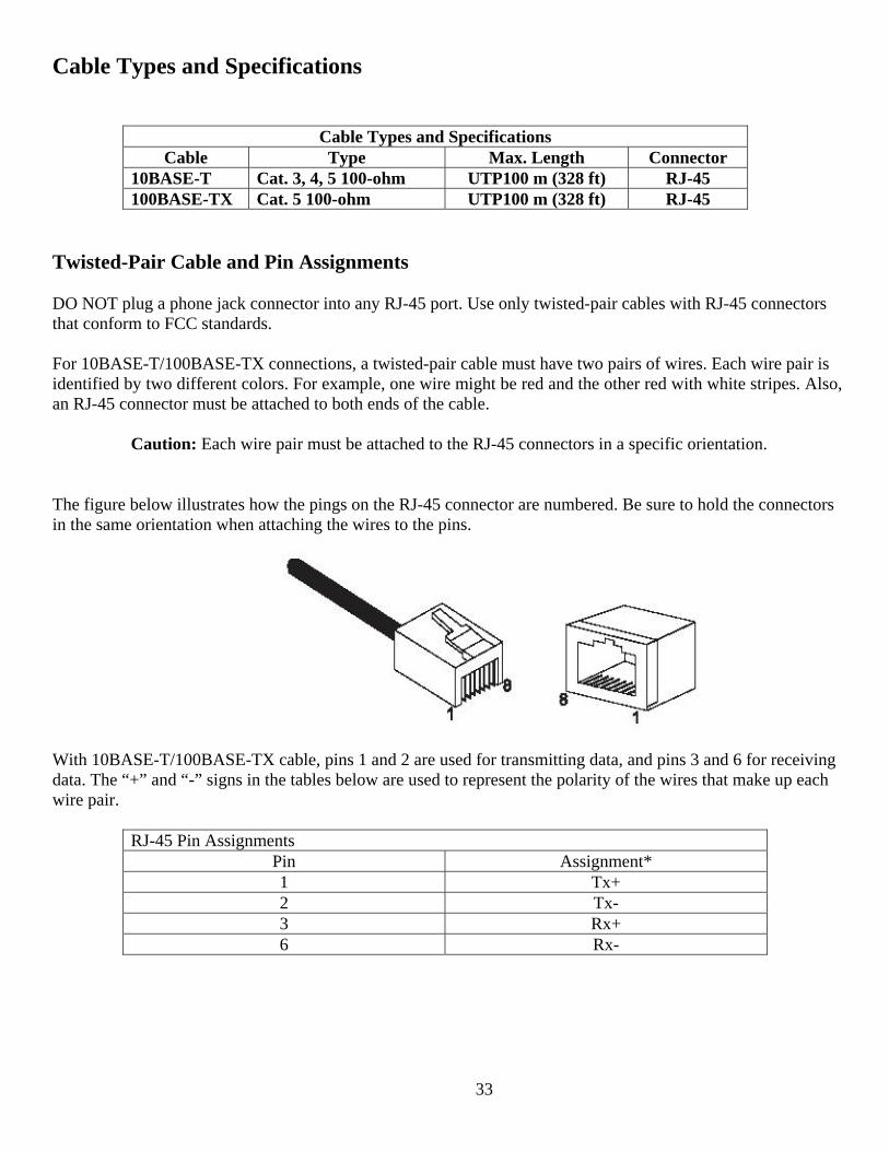
DO NOT plug a phone jack connector into any RJ-45 port. Use only twisted-pair cables with RJ-45 connectors that conform to FCC standards.
For 10BASE-T/100BASE-TX connections, a twisted-pair cable must have two pairs of wires. Each wire pair is identified by two different colors. For example, one wire might be red and the other red with white stripes. Also, an RJ-45 connector must be attached to both ends of the cable.
Caution: Each wire pair must be attached to the RJ-45 connectors in a specific orientation.
The figure below illustrates how the pings on the RJ-45 connector are numbered. Be sure to hold the connectors in the same orientation when attaching the wires to the pins.
With 10BASE-T/100BASE-TX cable, pins 1 and 2 are used for transmitting data, and pins 3 and 6 for receiving data. The “+” and “-” signs in the tables below are used to represent the polarity of the wires that make up each wire pair.
RJ-45 Pin Assignments
Pin Assignment* 1 Tx+ 2 Tx- 3 Rx+ 6 Rx-

34
Technical Specifications Standards: IEEE 802.3 10Base-T IEEE 802.3u 100Base-TX
Host Interface: PCI Bus Specification v2.2, 33/66 MHz
Data Bus Access: 32-bit bus mastering
LED: Link/Activity
Port: 1 RJ-45 for 10Base-T and 100Base-TX
Operating Systems:
NetWare 5.x NDIS Drivers Windows 2000 Windows 95, 98, ME, NT, 2000, XP SCO UNIX Linux
Operating Humidity: 10% - 90% (non-condensing)
Temperature: 32° – 131° F
Dimensions: 4.72 x 1.62 in
Weight: 0.10 lbs
Compliances/Certifications: FCC Class B CE-Mark AS/NZS 3548: 1995 Class B VCCI Class B
35
Terminology 10BASE-T: IEEE 802.3 specifications for 10 Mbps Ethernet over two pairs of Category 3, 4, or 5 UTP cable.
100BASE-TX: IEEE 802.3u specification for 100 Mbps Fast Ethernet over two pairs of Category 5 UTP cable.
1000BASE-T: IEEE 802.3ab specification for Gigabit Ethernet over four pairs of Category 5 UTP cable.
Adapter: A device used to connect end-user nodes to the network; each contains an interface to a specific type of computer or system bus, e.g. EISA, ISA, PCI, PCMCIA, CardBus, etc.
Auto-Negotiation: A signaling method that allows each node to define its operational mode (e.g., 1000 Mbps and half/full duplex) and to detect the operational mode of the adjacent node.
Backbone: The core infrastructure of a network. It is the portion of the network that transports information from one central location to another central location where it is unloaded onto a local system.
Bandwidth: The difference between the highest and lowest frequencies available for network signals. Also synonymous with wire speed, the actual speed of the data transmission along the cable.
Collision: A condition in which packets transmitted over the cable interfere with each other. The interference makes both signals unintelligible.
Collision Domain: Single CSMA/CD LAN segment.
CSMA/CD: CSMA/CD (Carrier Sense Multiple Access/Collision Detect) is the communication method employed by Ethernet and Fast Ethernet.
DHCP: Dynamic Host Configuration Protocol. This protocol automatically configures the TCP/IP settings of every computer on your home network.
DNS: DNS stands for Domain Name System, which allows Internet host computers to have a domain name (such as www.smc.com) and one or more IP addresses (such as 192.34.45.8). A DNS server keeps a database of host computers and their respective domain names and IP addresses, so that when a domain name is requested (as in typing "www.smc.com" into your Internet browser), the user is sent to the proper IP address. The DNS server address used by the computers on your home network is the location of the DNS server your ISP has assigned.
DSL: DSL stands for Digital Subscriber Line. A DSL modem uses your existing phone lines to transmit data at high speeds.
End Station: A workstation, server, switch, bridge or router.
Ethernet: A network communication system developed and standardized by DEC, Intel, and Xerox, using baseband transmission, CSMA/CD access, logical bus topology and coaxial cable. The successor IEEE 802.3 standard provides for integration into the OSI model and extends the physical layer and media with repeaters and implementations that operate on fiber, thin coax and twisted-pair cable.
36
Fast Ethernet: A 100 Mbps network communication system based on Ethernet and the CSMA/CD access method. Full Duplex: Transmission method that allows two network devices to transmit and receive concurrently, effectively doubling the bandwidth of that link.
Hub: Central connection device for shared media in a star topology. It may add nothing to the transmission (passive hub) or may contain electronics that regenerate signals to boost strength as well as monitor activity (active/intelligent hub). Hubs may be added to bus topologies; for example, a hub can turn an Ethernet network into a star topology to improve troubleshooting.
IEEE: Institute of Electrical and Electronic Engineers.
IEEE 802.3: Defines carrier sense multiple access with collision detection (CSMA/CD) access method and physical layer specifications.
IEEE 802.3u: Defines CSMA/CD access method and physical layer specifications for 100BASE-TX Fast Ethernet.
IP Address: IP stands for Internet Protocol. An IP address consists of a series of four numbers separated by periods, which identifies a single, unique Internet computer host. Example: 192.34.45.8.
ISP: Internet Service Provider. An ISP is a business that provides connectivity to the Internet for individuals and other businesses or organizations.
Local Area Network (LAN): A group of interconnected computer and support devices. It is made up of servers, workstations, a network operating system and a communications link. Servers are high-speed machines that hold programs and data shared by network users. The workstations (clients) are the users' personal computers, which perform stand-alone processing and access the network servers as required.
LAN Segment: Separate LAN or collision domain.
LED: Light emitting diode is used for monitoring a device or network condition.
MAC Address: MAC (Media Access Control) A MAC address is the hardware address of a device connected to a network.
Media Access Control (MAC): A portion of the networking protocol that governs access to the transmission medium, facilitating the exchange of data between network nodes.
MDI / MDI-X: Medium Dependent Interface - Also called an "uplink port," it is a port on a network hub or switch used to connect to other hubs or switches without requiring a crossover cable. The MDI port does not cross the transmit and receive lines, which is done by the regular ports (MDI-X ports) that connect to end stations. The MDI port connects to the MDI-X port on the other device. There are typically one or two ports on a device that can be toggled between MDI (not crossed) and MDI-X (crossed). Medium Dependent Interface – X (crossed) - A port on a network hub or switch that crosses the transmit lines coming in to the receive lines going out.

37
MII: Media Independent Interface, the standard interface for Fast Ethernet—similar to the AUI interface for traditional Ethernet.
Network Diameter: Wire distance between two end stations in the same collision domain.
PCI: Peripheral Component Interconnect - Local bus for PCs from Intel that provides a high-speed data path between the CPU and up to 10 peripherals (video, disk, network, etc.). The PCI bus runs at 33MHz supports 32-bit and 64-bit data paths, and bus mastering.
Static IP: If your Service Provider has assigned a fixed IP address; enter the assigned IP address, subnet mask and the gateway address provided by your service provider.
Subnet Mask: A subnet mask, which may be a part of the TCP/IP information provided by your ISP, is a set of four numbers configured like an IP address. It is used to create IP address numbers used only within a particular network (as opposed to valid IP address numbers recognized by the Internet.
Switched Ports: Ports that are on separate collision domains or LAN segments.
Transmission Control Protocol/Internet Protocol (TCP/IP): Protocol suite that includes TCP as the primary transport protocol, and IP as the network layer protocol.
TCP: Transmission Control Protocol - TCP and UDP (User Datagram Protocol) are the two transport protocols in TCP/IP. TCP ensures that a message is sent accurately and in its entirety. However, for real-time voice and video, there is really no time or reason to correct errors and UDP is used instead.
UDP: User Datagram Protocol - A protocol within the TCP/IP protocol suite that is used in place of TCP when a reliable delivery is not required. For example, UDP is used for real-time audio and video traffic where lost packets are simply ignored, because there is no time to retransmit. If UDP is used and a reliable delivery is required, packet sequence checking and error notification must be written into the applications.

FOR TECHNICAL SUPPORT, CALL:From U.S.A. and Canada (24 hours a day, 7 days a week)
(800) SMC-4-YOU; Phn: (949) 679-8000; Fax: (949) 679-1481From Europe : Contact details can be found on www.smc.com
INTERNETE-mail address:
Driver updates:http://www.smc.com/index.cfm?action=tech_support_drivers_downloads
World Wide Web:http://www.smc.com
For Literature or Advertising Response, Call:
U.S.A. and Canada: (800) SMC-4-YOU Fax (949) 679-1481Spain: 34-91-352-00-40 Fax 34-93-477-3774UK: 44 (0) 1932 866553 Fax 44 (0) 118 974 8701France: 33 (0) 41 38 32 32 Fax 33 (0) 41 38 01 58Italy: 39 (0) 3355708602 Fax 39 02 739 14 17Benelux: 31 33 455 72 88 Fax 31 33 455 73 30Central Europe: 49 (0) 89 92861-0 Fax 49 (0) 89 92861-230Nordic: 46 (0) 868 70700 Fax 46 (0) 887 62 62Eastern Europe: 34 -93-477-4920 Fax 34 93 477 3774Sub Saharan Africa: 216-712-36616 Fax 216-71751415North West Africa: 34 93 477 4920 Fax 34 93 477 3774CIS: 7 (095) 7893573 Fax 7 (095) 789 357PRC: 86-10-6235-4958 Fax 86-10-6235-4962Taiwan: 886-2-87978006 Fax 886-2-87976288Asia Pacific: (65) 238 6556 Fax (65) 238 6466Korea: 82-2-553-0860 Fax 82-2-553-7202Japan: 81-45-224-2332 Fax 81-45-224-2331Australia: 61-2-8875-7887 Fax 61-2-8875-7777India: 91-22-8204437 Fax 91-22-8204443
If you are looking for further contact information, please visit www.smc.com
Model Number: SMC1255TX-138 TeslaIrvine, CA 92618Phone: (949) 679-8000