Embed Size (px)
Citation preview

SMC-TR-93-45
N'1ý1'At-.Z'7"ý AEROSPACE REPORT NO.ADLJ'A268 736 TR-92(2935)-113•<•• •' •°•//Uf•~ ~~~iM/lllI//MNI2 6 3611111
Oil Absorption Into Cotton-Phenolic Material
Prepared by
P. A. BERTRANDMechanics and Materials Technology Center
Technology Operations LECT E
KELEcTE I
15 May 1993 IO27 •
Prepared for
SPACE AND MISSILE SYSTEMS CENTERAIR FORCE MATERIEL COMMAND
Los Angeles Air Force BaseP. 0. Box 92960
Los Angeles, CA 90009-2960
Engineering and Technology Group
THE AEROSPACE CORPORATIONEl Segundo, California
APPROVED FOR PUBLIC RELEASE;DISTRIBUTION UNLIMITED 93-19958

This report was submitted by The Aerospace Corporation, El Segundo, CA 90245-4691, underContract No. F04701-88-C-0089 with the Space and Missile Systems Center, P. O. Box 92960,Los Angeles, CA 90009-2960. It was reviewed and approved for The Aerospace Corporation byR. W. Fillers, Principal Director, Mechanics and Materials Technology Center. Capt. MarkBorden was the project officer for the Mission-Oriented Investigation and Experimentation(MOIE) program.
This report has been reviewed by the Public Affairs Office (PAS) and is releasable to the NationalTechnical Information Service (NTIS). At NTIS, it will be available to the general public,including foreign nationals.
This technical report has been reviewed and is approved for publication. Publication of thisreport does not constitute Air Force approval of the report's findings or conclusions. It ispublished only for the exchange and stimulation of ideas.
WM KYLE SNEDIjON, Capt, USAF Mark W. Borden,-Capt., USAF
Industrial & International Division MOEE MonitorPlans & Programs Directorate SMC/CIEB

40
UNCLASSIFIED,SECURrr CLASSIFICATION OF THIS PAGE
REPORT DOCUMENTATION PAGEla. REPORT SECURITY CLASSIFICATION lb. RESTRICTIVE MARKINGS
Unclassified2a. SECURITY CLASSIFICATION AUTHORITY 3. DISTRIBUTION(AVAILABILITY OF REPORT
2b. DECLASSFICATION/DOWNGRADING SCHEDULE Approved for public release; distribution unlimited
4. PERFORMING ORGANIZATION REPORT NUMBER(S) 5. MONITORING ORGANIZATION REPORT NUMBER(S)
TR-92(2935)- 13 SMC-TR-93-45
6a. NAME OF PERFORMING ORGANIZATION 6 b. OFFICE SYMBOL 7a. NAME OF MONITORING ORGANIZATIONThe Aerospace Corporation It Space and Missile Systems CenterTechnology Operations SpaceIndMissileSystemsCenter
6c. ADDRESS (Cty, State, and ZP Code) 7b. ADDRESS (Cly, State, and ZIP Code)
El Segundo, CA 90245-4691 Los Angeles Air Force BaseLos Angeles, CA 90009-2960
aa. NAME OF FUNDING/SPONSORING 8)b. OFFICE SYMBOL 9. PROCUREMENT INSTRUMENT IDENTIFICATION NUMBERORGANIZATION I a(ff/alcabie)
I F04701-88-C-0089
8c. ADDRESS (C0y, State. and ZiP Code) 10. SOURCE OF FUNDING NUMBERS
PROGRAM PROJECT TASK WORK UNIT
ELEMENT NO. NO. NO. ACCESSION NO.
11. TITLE (Indude Secuty Ctassi-atfon)
Oil Absorption Into Cotton-Phenolic Material
12. PERSONAL AUTHOR(S) Bertrand, P. A.
13a. TYPE OF REPORT 13b. TIME COVERED 14. DATE OF REPORT f'ewr Month. Day) 15. PAGE COUNTI FROM - TO_ 15 May 1993 27
16. SUPPLEMENTARY NOTATION
17. COSATI CODES 18. SUBJECT TE RMS (Continue on reverse if necessary and idoentity by block number)
FIELD GROUP SUB-GROUP
Lubrication, Cotton-Phenolic, Absorption
19. ABSTRACT (Contiue on reverse iffnecess~ary and Mlen*• by block n umber)
The kinetics of oil absorption into cotton-phenolic ball-bearing retainer material were determined.The results fit a model of two-step absorption in which the first step can be described by capillaryrise and the second step by diffusion of oil from the capillaries into the bulk phenolic resin. Thecapillaries are associated with the cotton threads and are on the order of several lim or less in radius.The model successfully describes data for two cotton-phenolics with different cloth weaves, andfive nonpolar liquids (four lubricating oils and heptane) with viscosities that vary over 3 orders ofmagnitude. The total amount of oil absorbed at the completion of the first step (1.5 to 3.4% v/v inthis work) is proportional to the volume of the sample, not its surface area, suggesting that the entirevolume of the material stores oil and not just the surface region. If the material is not completelydry when submerged in oil, the capillaries are blocked and only surface absorption of oil can takeplace. The saturation amount of oil in the resin after diffusion is complete is about 2 to 3 % v/v (not
20. DIS'rRIBUTIONAVAILABILITY OF ABSTRACT 21. ABSTRACT SECURITY CLASSIFICATION
2 UNCLASSIFEDUNLIMITED 1' SAME AS RPT. DTIC USERS Unclassified22L. NAME OF RESPONSIBLE INDIVIDUAL 22b. TELEPHONE (IndclueArea Coda) 22c. OFFICE SYMBOL
DO FORM 1473,84 MAR 83 APR edlillon may be used unlil exhausted. SECURITY CLASSIFICATION OF THIS PAGE:All other edilions are obsolete. UNCLASSIFIED
UNCLASSIFIEDsECURIY CLASSFICATION OF ThIS PAGE
including the amount of oil stored in the capillaries). The diffusion coefficient calculated using our
model is 3 x 10.12 cm2/s, which is reasonable when compared with available literature data on largeand small molecules diffusing into polymers.
UNCLASSIFIEDSECURITY CLASSFICATION OF THIS PAGE

PREFACE
This work was supported by the Air Force Materiel Command, Space and Missile Systems Centerunder contract F04701-88-C-0089.
•rI(• •O ~ ci'u'-- ,. LOI•ED 3
s.e.sion Torw
DTIC TAB 0Unannouceed0Justifioat i
BYDist ri but W./
hvaillbil Ity aAAvail and/or
Dist
Spe a2l
CONTENTS
I. INTRODUCTION ................................................................................................................ 7
II. EXPERIM ENTAL ................................................................................................................ 9
A. COT rO N-PHEN OLIC M ATERIALS ........................................................................... 9
B. LU BRICATIN G OILS ................................................................................................... 11
C. EXPERIM ENTAL PROCEDURE ................................................................................. 11
II. RESULTS ............................................................................................................................. 13
IV . M ODEL AND DISCU SSION .............................................................................................. 17
A FIRST STEP - CAPILLARY RISE ........................................................................... 17
B. SECOND STEP - DIFFUSION .................................................................................. 20
IV . CONCLU SION S ................................................................................................................... 25
REFERENCES .............................................................................................................................. 27
3

FIGURES
1. Cotton-phenolic ball-bearing retainer material, as received and sectioned. ........................... 9
2. Photomicrographs of the cotton-phenolic materials, cross-sectioned to viewthe surface bounded by h and w in Fig. 1 ............................................................................... 10
3. Coray 100 absorption into Westinghouse 97 cotton-phenolic .............................................. 13
4. Coray 100 absorption into Spaulding FBEFW cotton-phenolic ........................................... 14
5. Heptane absorption into Westinghouse 97 cotton-phenolic ................................................... 14
6. Final volume of liquid absorbed in first step for Westinghouse 97 material ......................... 19
7. Coray 100 absorption into Westinghouse 97 cotton-phenolic .............................................. 21
8. Long-term diffusion of Cory 100 into Westinghouse 97 cotton-phenolic ............................. 22
TABLES
1. Selected Fluid Properties (25"C) ........................................................................................... 11
2. Capillary-Fill Parameters ........................................................................................................ 18
3. Oil Diffusion into Phenolic Resin ........................................................................................... 23
5

I. INTRODUCTION
Cotton-phenolic material is used in the ball retainers, also called cages, of many ball bearings. Thematerial can absorb lubricating oil; in fact, oil is impregnated into the retainers in the hopes that theretainer will function as an oil reservoir (i.e., a resupply system). Oil is absorbed into the materialquickly at first, and then more slowly for long periods of time. In engineering practice, the initialfilling is accomplished at least in part by vacuum-impregnating the retainer in warm oil. In this pro-cess, the retainer is held above a container of warm oil in a chamber that is then evacuated. Theretainer is immersed into the oil and allowed to soak for a period of time, varying from a few hours toa few days. The long-term absorption of oil has never been discussed. If ball retainers continue toabsorb oil during storage and use, they could be a sink for lubricant instead of a source. 1 This wouldhave a deleterious effect on the operation of lightly lubricated ball bearings with no oil-replenishmentscheme, such as those found in many spacecraft.
The mechanism of oil absorption into cotton-phenolic material has never been determined. In the workreported here, we have varied the properties of the cotton-phenolic materials and the absorbing fluids,observed the kinetics of the oil-absorption process, and developed a model that describes the experi-mental data very well. Retainer-grade cotton-phenolic material was used in the experiments; actualmachined retainers were also studied in concurrent experiments, but the results of those experiments arenot reported here. The mechanism of oil absorption is the same for pieces of material and retainers, butthe data analysis is much less complicated for the pieces due to their simple shapes (see below).
The model we have developed to describe oil absorption into cotton-phenolic material is based on theanisotropic and composite nature of the material. Cotton-phenolic material is manufactured as tubesby winding cotton cloth impregnated with resin precursors on a mandrel, followed by curing at ele-vated temperatures. The rates and quantities of oil absorbed are dependent on the specific locationwithin a tube and material handling procedures. The material is a composite (resin plus cloth) andstructurally anisotropic (due to the thread directions). The experiments described below show that oilis absorbed into the material by a two-step mechanism: first, oil is absorbed by capillary action intovoids associated with the fibers within the cotton threads; then a slow diffusion of oil into the bulkphenolic resin takes place.
7

II. EXPERIMENTAL
A. COTTON-PHENOLIC MATERIALSTwo different cotton-phenolic materials were used in the experiments; they were manufactured withcotton cloths of different weaves. Westinghouse 97, produced by Westinghouse Electric Corp., ismade with a 4-oz/yd cloth (26 x 26 to 35 x 35 thread matrix on I cm2 of cloth). Spaulding FBEFW,produced by the Spaulding Composites Company, is made with a 3-oz/yd cioth (approximately 35 x40 matrix on 1 cm 2 of cloth). The weight of the cloth in the Spaulding FBEFW is less than that inWestinghouse 97 because even though there are more threads, each thread is finer. 'The threads arebundles of about 100 cotton fibers twisted together. Each fiber has an oval cross section, about 5 x 25pim, and the spaces between the fibers in a thread are comparable in size to the fibers themselves, witha typical linear dimension of 0 to 50 pm. The fibers and any spaces surrounding them that are notfilled by cured resin have been thought of traditionally as "wicks" that draw oil into the material.
The materials were received as cylindrical sections as shown in Fig. 1. The warp threads of the clothHe parallel to the axis of the cylinder; the weft threads are wound around the cylinder. Figure 2 shows
SPAULDING FBEFW
dl dl = 3.810 cmd2 = 5.032 cmh = 1.615 cm
: : l -' w=0.61lcm(cl and c2 are variable)
Cl WESTINGHOUSE 97dj = 3.368 cm
hd2 = 5.390 cmh = 1.219 cm
W = 1.011 cm(cl and c2 are variable)
RETAINER MATERIAL WHOLE AND SECTION
Figure 1. Cotton-phenolic ball-bearing retainer material, as received and sectioned.
9

b. b
•• r ,"'N :I I •- .1 - " " -~
Figure 2. Photomicrographs of the cotton-phenolic materials, cross-sectioned toview the surface bounded by h and w in Fig. 1. (a) Westinghouse 97: 50X andl00X; (b) Spaulding FBEFW: 50X and 100X.
photomicrographs of the two materials. The surface photographed is that bounded by h and w in Fig.1. The warp threads are seen as wavy lines across the photomicrographs; the weft threads are viewedend-on. The densities were determined by weighing the tubes as received and dividing the weight bythe tube volume. The densities are 1.251 g/cm3 f'co Westingthouse 97 and 1.238 g/cm3 for SpauldingFBEFW. The density of the composite is affected by the weave and density of the cotton cloth andalso by the cure of the resin. Some low-density resins contain many bubbles that developed duringcure. These bubbles are possible sites for oil storage. Many bubbles can be observed in thephotomicrographs of the Spaulding material, while only a few can be seen in the Westinghousematerial. The surfaces displayed in these photomicrographs were selected at random and are notnecessarily typical of the entire sample as regards bubble distribution. However, more bubbles couldbe a contributing factor in the lower density of the Spaulding material. When converting sampleweights to volumes, the weights measured before sample cleaning and drying were used, since thiswas the state of the phenolic tubes when the densities were determined.
10

B. LUBRICATIN -S OILSFour oils werc "sed in these experiments. They and their selected properties are listed in Table 1.Coray 100 is a petroleum-based, naphthenic oil produced by Exxon. Nye 176H is a synthetic hydro-carbon (poly-ox-olefin) fluid formulated by William F. Nye, Inc. Pennzane SHF X2000 is a multiplyalkylated cyclopentane synthetic hydrocarbon produced by Pennzoil Products Co. Krytox 143AB is aperfluoropolyalkylether produced by E. I. Du Pont de Nemours & Co., Inc. The solvent used forcleaning the cotton-phenolic material, and as the absorbate in several of the kinetic experiments, wasHPLC-grade heptane. Those properties of heptane relevant to the experiments are also listed inTable 1.
C. EXPERIMENTAL PROCEDURESmall sections of cotton-phenolic material were sawed out of the tubes as shown in Fig. 1, weighed,Soxhlet-extracted overnight in heptane, baked overnight in vacuum at 1 100C, and weighed againquickly in the presence of a desiccant. Cotton-phenolic material absorbs water very quickly, and aswill be discussed below, water absorption interferes with oil absorption.
Most of the samples were immersed in containers of oil or heptane immediately after weighing.Several samples were exposed to laboratory air for about two months to allow equilibration with atmo-spheric humidity (this length of time was determined to be sufficient by other experiments) beforebeing placed in the oil baths. The oil- or heptane-filled containers were kept at room temperature indesiccators for the duration of the experiment. Periodically the samples were removed, centrifuged at680 G to remove excess oil, weighed, and returned to their baths. The experiments were continueduntil some of the samples were saturated with oil. The samples from the heptane bath were removedand weighed quickly without centrifuging to avoid excessive evaporation of the volatile absorbate.
Table 1. Selected Fluid Properties (25"C)
11 (poise) p (g/cm3 ) y (dyne-cm)
Coray 100 3.67 0.9176 =20
Nye 176H 10.2 0.85 =20
Krytox 3.78 1.89 18.5143AB
Pennzane 2.21 0.85 =20SHF X2000
heptane 0.00386 0.684 =20
11 .

MI. RESULTS
The results of some of the experiments are shown in Figs. 3 through 5. The ordinate is the actualweight increase in the samples after baking. The different symbols correspond to different test sam-ples. The vertical displacements of the data for the various samples in any one figure are due to thefact that all the samples have slightly different sizes and weights initially, and the data presented inthe figures are not normalized. In the discussion below, the data will be broken down for analysis,arxd appropriate normalizations will be chosen.
25 "-
Ch 20 - ,E
Co)
cc (a)
~10
S50
0 1E+5 2E+5 3E+5 4E+5 5E+5TIME, min
25 -
n20 -ELj
~15c-co REIO (b)
10€.9 REGION 23. 5
REGION I
o 100 200 300 400 500 600 700TIMEt/2, rainl/2
Figure 3. Coray 100 absorption into Westinghouse 97 cotton-phenolic. The dif-ferent symbols correspond to different test samples. (a) Unnormalized weightincrease vs. time. (b) Unnormalized weight increase vs. square root of time.
13

35
30E
,l 25C/)
Lu 200 REGON 3SAMPLES
- 15
AIR-EQUILIBRATED SAMPLES0 I I
0 100 200 300 400 500 600 700
Figure 4. Coray 100 absorption into Spaulding FBEFW cocton-phenolic;umnonnalized weight increase vs. square roo of time. The different symbolscorrespond to different test samples.
14
12
El1OCo.
6-
00 50 100 150 200 250 300 350TIME1/2, minli2
Figure 5. Heptane absorption into Westinghouse 97 cotton-phenolic; unnormal-ized weight increase vs. square root of time.
14

The absorption of oil into extracted pieces of cotton-phenolic material starts quickly and then slowsdown. Heptane absorption follows the same trend as oil absorption. The data for each sample can bedivided into two or three sections in which the weight increase is proportional to the square root oftime spent in the fluid bath (see Fig. 3b and Fig. 4).
Since the process described by Region 3 is very slow compared to those of Regions 1 and 2, theweight increase due to it can be easily removed in a first approximation. The intercept of the linedescribing Region 3 with t = 0 can be taken as the amount of weight increase due solely to the pro-cesses described in Regions 1 and 2, and the slopes of the lines describing these regions can be con-sidered to be unaffected by the process described in Region 3.
15

IV. MODEL AND DISCUSSION
Our model of the absorption process assumes that absorption proceeds by a two-step mechanism. Inthe first step, oil is wicked up into capillaries within the yarn. This process saturates and stops whenthe capillaries are filled. In the second step (which is actually concurrent with the first but so muchslower that it can be treated as subsequent), oil diffuses from these capillaries as well as through theexternal surface of the samples into the bulk resin. Heptane absorption proceeds by the same mecha-nism. (Water absorption is not addressed by this work; water is a polar molecule and may absorb viaa different mechanism.)
A. FIRST STEP - CAPILLARY RISE
The rate of fluid rise in a capillary can be approximated by 2
h(t) 2yr '(1
where h(t) is the height filled at a time t, y is the surface tension of the fluid, r is the radius of thecapillary, and 11 is the viscosity of the fluid. In the initial calculations, we shall assume the presenceof one capillary per thread, and will discuss the extension to multiple capillaries later. The capillariesin adjacent threads are assumed to be unconnected. In our experiments, we measure the weight gain,which is a function of the height and the cross-sectional area of the capillary as well as the density ofthe fluid (p). The weight gain as a function of time per capillary is
w(t) = ir r2 p 2yr (2)
The only adjustable parameter in this equation is r, which must be on the order of gtm because of thestructure of the material, as discussed above.
1. Capillary Radius
The samples used in these experiments were all of the same general shape (Fig. 1), but of differentsizes. Each sample has warp threads (parallel to h in Fig. 1; 1.2-cm long for Westinghouse 97, and1.6-cm long for Spaulding FBEFW) and weft threads (parallel to c I and c2 in Fig. 1; 0.2 to 1.1 cmlong). The weft threads were severed during sample preparation. The number of warp threads andweft threads for each sample can be calculated approximately from the size of the sample and theweave of the cloth. In the Westinghouse 97 samples, there are 1440 weft threads (2880 capillaryentrances) and from 150 to 580 warp threads (300 to 1160 capillary entrances). In the SpauldingFBEFW samples, there are 1950 weft threads (3900 capillary entrances) and from 370 to 760 warp
17
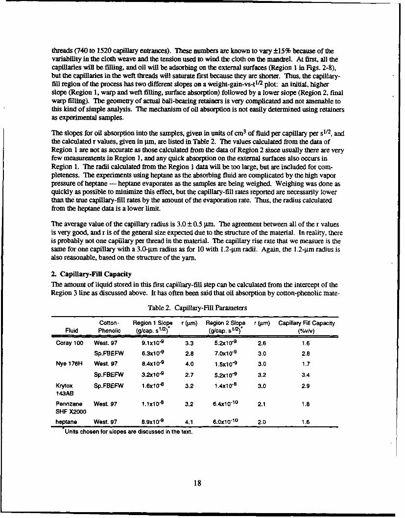
threads (740 to 1520 capillary entrances). These numbers are known to vary ±15% because of thevariability in the cloth weave and the tension used to wind the cloth on the mandrel. At first, all thecapillaries will be filling, and oil will be adsorbing on the external surfaces (Region I in Figs. 2-8),but the capillaries in the weft threads will saturate first because they are shorter. Thus, the capillary-fill region of the process has two different slopes on a weight-gain-vs-t'/2 plot: an initial, higherslope (Region 1, warp and weft filling, surface absorption) followed by a lower slope (Region 2, finalwarp filling). The geometry of actual ball-bearing retainers is very complicated and not amenable tothis kind of simple analysis. The mechanism of oil absorption is not easily determined using retainersas experimental samples.
The slopes for oil absorption into the samples, given in units of cm 3 of fluid per capillary per s1 2, andthe calculated r values, given in Jim, are listed in Table 2. The values calculated from the data ofRegion 1 are not as accurate as those calculated from the data of Region 2 since usually there are veryfew measurements in Region 1, and any quick absorption on the external surfaces also occurs inRegion 1. The radii calculated from the Region 1 data will be too large, but are included for com-pleteness. The experiments using heptane as the absorbing fluid are complicated by the high vaporpressure of heptane - heptane evaporates as the samples are being weighed. Weighing was done asquickly as possible to minimize this effect, but the capillary-fill rates reported are necessarily lowerthan the true capillary-fill rates by the amount of the evaporation rate. Thus, the radius calculatedfrom the heptane data is a lower limit.
The average value of the capillary radius is 3.0 ± 0.5 jLrn. The agreement between all of the r valuesis very good, and r is of the general size expected due to the structure of the material. In reality, thereis probably not one capillary per thread in the material. The capillary rise rate that we measure is thesame for one capillary with a 3.0-jim radius as for 10 with 1.2-tim radii. Again, the 1.2-lim radius isalso reasonable, based on the structure of the yarn.
2. Capillary-Fill Capacity
The amount of liquid stored in this first capillary-fill step can be calculated from the intercept of theRegion 3 line as discussed above. It has often been said that oil absorption by cotton-phenolic mate-
Table 2. Capilary-Fill Parameters
Cotton- Region 1 Slope r (gim) Region 2 Slope r (,um) Capillary Fill CapacityFluid Phenolic (g/cap. s1/2). (g/cap. s1/2)* (%v/v)
Coray 100 West. 97 9.1x10"9 3.3 5.2x10 9 2.6 1.6
Sp.FBEFW 6.3x10⁻⁹ 2.8 7.0x10 9 3.0 2.8
Nye 176H West. 97 8.4x1 09 4.0 1.5x1 0-9 3.0 1.7
Sp.FBEFW 3.2010-9 2.7 5.2x1 0-9 3.2 3.4
Krytox Sp.FBEFW 1.6x10"8 3.2 1.4x10"8 3.0 2.9143AB
Pennzane West. 97 1.1x10"8 3.2 6,4x10 10 2.1 1.8SHF X2000
heptane West. 97 8.9x10⁻⁹ 4.1 6.0x10"10 2.0 1.6
Units chosen for slopes are discussed in the text.
18

rial is a surface process; the experiments reported here indicate that the amount of oil or heptanestored within the material is dependent on the sample volume, not the surface area. In Fig. 6a, thevolume of absorbate contained within each Westinghouse 97 sample is plotted as a function of samplevolume; in Fig. 6b, the volume of stored absorbate is plotted as a function of sample surface area.
10
N 6-0 (a)
-,
E
IA-
0 0.1 0.2 0.3 0.4 0.5 0.6
SAMPLE VOLUME, cm3
'6 8 024S(a)
IL
A06A
F0.F0 0 0.1 0.2 0.3 0.4 0.5 0.6SAM PLEfVcLMEec.1__9
0J0 (b)34
SAPEETRA SRAEAK =
Fiue6L iaLoueo lqi bobdi is se o etnhue9
maeil 0a safnto fsml oue ()a ucino apeetrnal srfacearea
C.)9

The lines are the best fit of the data (not including the data for the two smallest samples). The twosmallest samples were used as a test case. It is clear that the data for the two smallest samples fits therelationship based on volume, but not that based on surface area. Thus, the amount of oil storeddepends on sample volume. The rate of absorption depends on the number of capillaries (which is afunction of surface area), but the final stored volume of oil depends only on the volume of the cotton-phenolic material.
The capillary-fill capacity is reported as % (v/v) in Table 2. The different materials have differentcapillary-fill capacities, which are not necessarily correlated with the weave of the cloth. (In fact, inthe oil absorption experiments using actual retainers, the capillary fill capacity is definitely not corre-lated with weave.) In addition, the volume available for oil storage within the =3-jim radius capillar-ies is too small to account for the total amount of oil absorbed by the material in this step.
One possible explanation for this behavior is that the capillary-fill capacity is related to the phenolicresin cure state. There are bubbles within the cotton-phenolic material, presumably the result of gasevolution during cure, that are intersected by the threads. These bubbles could be the major storagevolume for oil within the material. The access to the bubbles is regulated by the capillaries (the rateat which the bubbles fill is controlled by the threads), but the volume of oil that can be absorbed isrelated to the cure of the resin (the number and size of the bubbles). The cure is probably a strongfunction of the manufacturer because each manufacturer has his own cure recipe, and probably variesfrom lot to lot. Thus, the Spaulding material could have a different cure state than the Westinghousematerial. Of course, this is a very speculative hypothesis.
3. Effect of MoistureFigure 3 shows the absorption data for Spaulding FBEFW filling with Coray 100. The samples thatwere dry when immersed into oil show much more oil absorption than those that were equilibratedwith air. Water vapor, which is present in the air, has absorbed into the cotton-phenolic material andformed a barrier to oil penetration. This illustrates the importance of complete drying of ball-bearingretainers before oil impregnation.
B. SECOND STEP - DIFFUSION
The second, slow step of the oil absorption process is suggested to be diffusion of the oil into the bulkphenolic resin.
The solution of the diffusion equation for saturation of a plane sheet is
M___ t 1._. 1 ep-D (2m + I12)TC2--1 (1)
Msat - 2 _MO (2m + 1)2 [2J(
where Mt is the uptake at time t, Msat is the saturation uptake, 2f is the thickness of the sheet, and D isthe diffusion coefficient 3 Over a limited initial period of time, diffusion processes can be fit to asimple absorption amount vs. t1r2 relationship. 3 The diffusion step appears as the linear Region 3when the data are plotted as a function of the square root of time in Figs. 3 through 5.
20
The data are used to predict the saturation weight of oil in a particulai ýece of cotton-phenulic, Mst,and this weight is used to normalize the data for that sample. EquatioL ')is then fit to the data, usingD/2 as an adjustable parameter. In what follows, this parameter will bi -ported for each oil/cotton-phenolic combination. The separation of D and t will be addressed in m, detail below.
1. Diffusion-Fill Capacity
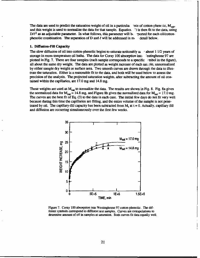
The slow diffusion of oil into cotton-phenolic begins to saturate noticeably ai - about 1 1/2 years ofstorage in room-temperature oil baths. The data for Coray 100 absorption into Testinghouse 97 areplotted in Fig. 7. There are four samples (each sample corresponds to a specific %,mbol in the figure),all about the same dry weight. The data are plotted as weight increase of each sarwi.le, unnormalizedby either sample dry weight or surface area. Two smooth curves are drawn through the data to illus-trate the saturation. Either is a reasonable fit to the data, and both will be used below to assess theprecision of the analysis. The projected saturation weights, after subtracting the amount of oil con-tained within the capillaries, are 17.0 mg and 14.8 mg.
These weights are used as Msat to normalize the data. The results are shown in Fig. 8. Fig. 8a givesthe normalized data for M..t = 14.8 mg, and Figure 8b gives the normalized data for Msat = 17.0 mg.The curves are the best fit of Eq. (3) to the data in each case. The initial few days do not fit very wellbecause during this time the capillaries are filling, and the entire volume of the sample is not pene-trated by oil. The capillary-fill capacity has been subtracted from Mt at t = 0. Actually, capillary filland diffusion are occurring simultaneously over the first few weeks.
35
30
Msm = 17.0 mg25 .
Eud Msat = 14.8 mgU)<c 20cr
C.)2t
S15
ILU
3: 10
5
05E+5 1E+6 1.5E+6
TIME, min
Figure 7. Coray 100 absorption into Westinghouse 97 cotton-phenolic. The dif-ferent symbols correspond to different test samples. Curves are extrapolations todetermine amount of oil in samples at saturation. Both curves fit data equally well.
21

1.0
0.8 e
-0.6
0.4
0.2 MW = 14.8 mgDI12 = 4"2 X 10⁻⁷ mi 1
0 1i I0 2E+5 4E+5 6E+5 8E+5 1E+5
TIME, min
1.0
0.8 -
-0.6(b)
S0.4 -
0.2 Mot = 17.0 mgD/12 = 3.1 X 10⁻⁷ Min-1
00 1 I I I0 2E+5 4E+5 6E+5 8E+5 1E+5
TIME, min
Figure 8. Long-term diffusion of Cory 100 into Westinghouse 97 cotton-Phenolic. The different symbols correspond to different test samples. Curvesae best fit to the data. (a) Saturation oil weight of 14.8 mg in the samples. (b)Saturation oil weight of 17.0 mg in the samples.
22
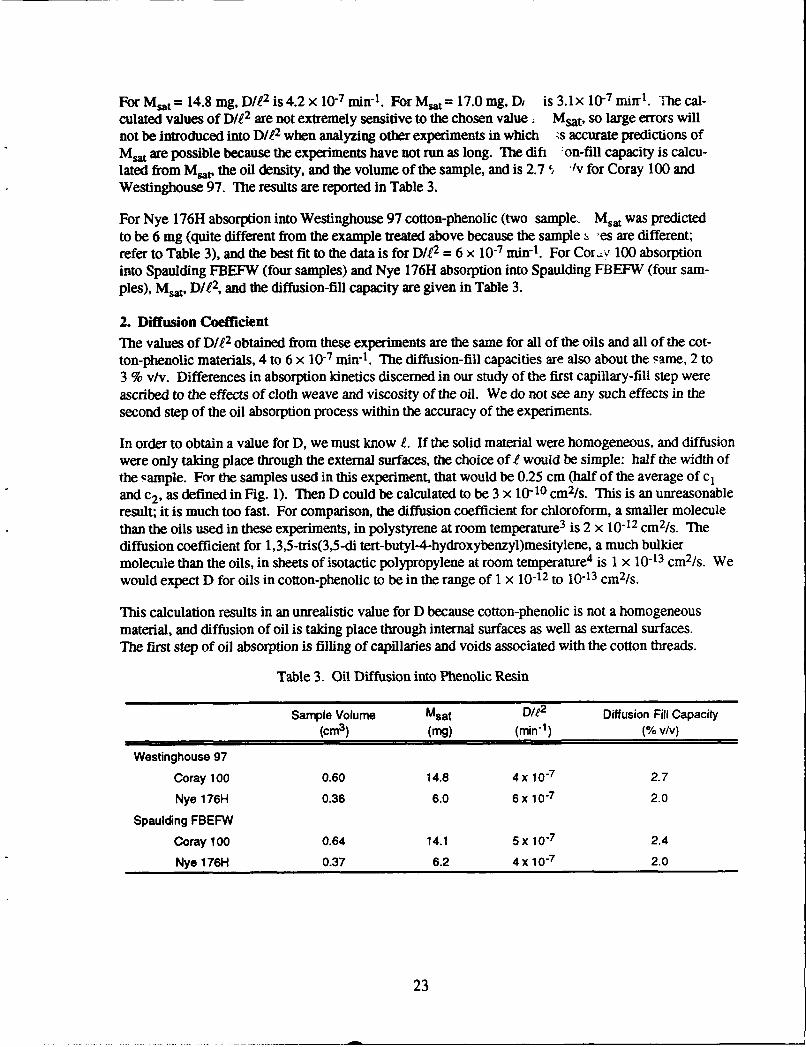
For Msat = 14.8 mg, D/ 2 is 4.2 x 10- min-1 . For Msat= 17.0 mg, Di is 3.1x 10⁻⁷ mir t . The cal-culated values of D/1 2 are not extremely sensitive to the chosen value . Msat, so large errors willnot be introduced into D/M2 when analyzing other experiments in which ;s accurate predictions ofMsat are possible because the experiments have not run as long. The difi :on-fill capacity is calcu-lated from Msat, the oil density, and the volume of the sample, and is 2.7 $/v for Coray 100andWestinghouse 97. The results are reported in Table 3.
For Nye 176H absorption into Westinghouse 97 cotton-phenolic (two sample. Ms,, was predictedto be 6 mg (quite different from the example treated above because the sample s 'es are different;refer to Table 3), and the best fit to the data is for D/t 2 = 6 x 10⁻⁷ min-1 . For Cob'y 100 absorptioninto Spaulding FBEFW (four samples) and Nye 176H absorption into Spaulding FBEFW (four sam-pies), Mst, Die2, and the diffusion-fill capacity are given in Table 3.
2. Diffusion Coefficient
The values of D/12 obtained from these experiments are the same for all of the oils and all of the cot-ton-phenolic materials, 4 to 6 x 10⁻⁷ min-1. The diffusion-fill capacities are also about the same, 2 to3 % v/v. Differences in absorption kinetics discerned in our study of the first capillary-fill step wereascribed to the effects of cloth weave and viscosity of the oil. We do not see any such effects in thesecond step of the oil absorption process within the accuracy of the experiments.
In order to obtain a value for D, we must know e. If the solid material were homogeneous, and diffusionwere only taking place through the external surfaces, the choice of e would be simple: half the width ofthe sample. For the samples used in this experiment, that would be 0.25 cm (half of the average of c1
and c2 , as defined in Fig. 1). Then D could be calculated to be 3 x 10⁻¹⁰ cm2/s. This is an unreasonableresult; it is much too fast. For comparison, the diffusion coefficient for chloroform, a smaller moleculethan the oils used in these experiments, in polystyrene at room temperature 3 is 2 x 10-12 cm 2/s. The
diffusion coefficient for 1,3,5-tris(3,5-di tert-butyl-4-hydroxybenzyl)mesitylene, a much bulkiermolecule than the oils, in sheets of isotactic polypropylene at room temperature4 is 1 x 10-13 cm 2/s. Wewould expect D for oils in cotton-phenolic to be in the range of 1 x 10-12 to 10-13 cm 2/s.
This calculation results in an unrealistic value for D because cotton-phenolic is not a homogeneousmaterial, and diffusion of oil is taking place through internal surfaces as well as external surfaces.The first step of oil absorption is filling of capillaries and voids associated with the cotton threads.
Table 3. Oil Diffusion into Phenolic Resin
Sample Volume Msat Die2 Diffusion Fill Capacity(cm3 ) (mg) (min"1) (% v/v)
Westinghouse 97
Coray 100 0.60 14.8 4 x 10⁻⁷ 2.7
Nye 176H 0.36 6.0 6 x 10- 7 2.0
Spaulding FBEFW
Coray 100 0.64 14.1 5 x 10⁻⁷ 2.4
Nye 176H 0.37 6.2 4 x 10⁷ 2.0
23

Oil then diffuses out into the bulk phenolic resin from each of the capillaries and voids. The distanceover which diffusio -s taking place is the distance between the capillaries, not just the distancebetween the edges of the samples.
The distance between the capillaries can be approximated by the distance between cotton threads,since the capillaries are associated with the threads. For Westinghouse 97, this distance is 0.048 cm,and for Spaulding FBEFW (with a tighter weave), this distance is 0.036 cm. We can reasonablyassume then an I of 0.02 cm for both materials. This leads to a diffusion coefficient of 3 x 10-12cm2/ s for these oils into phenolic resin. This value is reasonable compared with the literature valuesfor diffusion of organic molecules into polymers, as quoted above.
24

IV. CONCLUSIONS
The absorption of five nonpolar liquids with different physical properties ii. cotton-phenolic ball-bearing retainer material has been measured. We propose a two-step mecha --m for the oil absorp-tion process. The oils (and heptane) are initially absorbed into unconnected c. illaries in the threadsof the cotton cloth; the physical properties of the fluid (density, viscosity, etc.). d the weave of thecloth (number of capillaries per unit surface area) determine the capillary-fill ratt The chemicalcomposition of the liquids used in these experiments does not affect the process, p. -bably because themolecules are all nonpolar and have no specific chemical interactions with either the cotton threads orthe phenolic resin. The amount of oil that can be stored in this step is different for cotton-phenolicfrom different manufacturers, and we speculate that this may be correlated with bubbles within thematerial due to different cure states.
The long-term absorption of oil into cotton-phenolic material can be modeled as diffusion of oil fromcapillaries and voids associated with the cotton threads into the bulk phenolic resin. The saturationamount of oil in the resin is about 2 to 3 % v/v. The diffusion coefficient calculated using this modelis 3 x 10-12 cm 2/s, which is reasonable when compared with available literature data on large andsmall molecules diffusing into polymers. If one assumes that oil only penetrates from the outer sur-face of the samples, the calculated diffusion coefficient is unreasonably fast.
Several results from this work have direct implications for the use of cotton-phenolic retainers in oil-lubricated ball bearings. First, retainers must be dry before immersion in oil, or very little oil will beabsorbed. Second, changing the cloth weave will not have any great effect on the amount of oilstored in a retainer. (Changing the manufacturer or the required density of the phenolic might affectthe stored oil amount.) Third, oils of different viscosities will absorb at different rates, which can becalculated from the model. It is probable that soaking a retainer in oil for only a few hours, as issometimes done in industry, results in an incompletely filled retainer. Such a retainer may then con-tinue to absorb oil from its bearing during storage, resulting in less than optimal performance.
Saturation of the material with oil occurs only after about two years of storage in a room temperatureoil bath. If this diffusion takes place in a stored, lubricated bearing it may affect the availability of oilduring later bearing use. For a lightly lubricated bearing where a thin oil film is in contact with theretainer, creep of the oil and absorption into the retainer over long storage times could constitute aserious oil-depletion mechanism.
25
REFERENCES
1. L. M. Dormant and S. Feuerstein, J. Spacecr. and Rockets 13, 306(1 G6); 755(1976).
2. J. J. Bikerman, Physical Surfaces, Academic Press, New York, 1970.
3. J. Crank, The Mathematics of Diffusion, the Clarendon Press, Oxford, (1M ').
4. T. Schwartz, G. Steiner, and J. Koppelmann, J. Appl. Polymer ScL 38, 1(19b 1)
27

TECHNOLOGY OPERATIONS
The Aerospace Corporation functions as an "architect-engineer" for national securityprograms, specializing in advanced military space systems. The Corporation's TechnologyOperations supports the effective and timely development and operation of national securitysystems through scientific research and the application of advanced technology. Vital to thesuccess of the Corporation is the technical staffs wide-ranging expertise and its ability to stayabreast of new technological developments and program support issues associated with rapidlyevolving space systems. Contributing capabilities are provided by these individual TechnologyCentes:
Electronics Technology Center: Microelectronics, solid-state device physics,VLSI reliability, compound semiconductors, radiation hardening, data storagetechnologies, infrared detector devices and testing; electro-optics, quantum electronics,solid-state lasers, optical propagation and communications; cw and pulsed chemicallaser development, optical resonators, beam control, atmospheric propagation, andlaser effects and countermeasures; atomic frequency standards, applied laserspectroscopy, laser chemistry, laser optoelectronics, phase conjugation and coherentimaging, solar cell physics, battery electrochemistry, battery testing and evaluation.
Mechanics and Materials Technology Center: Evaluation and characterizationof new materials: metals, alloys, ceramics, polymers and their composites, and newforms of carbon; development and analysis of thin films and deposition techniques;nondestructive evaluation, component failure analysis and reliability; fracturemechanics and stress corrosion; development and evaluation of hardened components;analysis and evaluation of materials at cryogenic and elevated temperatures; launchvehicle and reentry fluid mechanics, heat transfer and flight dynamics; chemical andelectric propulsion; spacecraft structural mechanics, spacecraft survivability andvulnerability assessment; contamination, thermal and structural control; hightemperature thermomechanics, gas kinetics and radiation; lubrication and surfacephenomena-
Space and Environment Technology Center: Magnetospheric, auroral andcosmic ray physics, wave-particle interactions, magnetospheric plasma waves;atmospheric and ionospheric physics, density and composition of the upperatmosphere, remote sensing using atmospheric radiation; solar physics, infraredastronomy, infrared signature analysis; effects of solar activity, magnetic storms andnuclear explosions on the earth's atmosphere, ionosphere and magnetosphere; effectsof electromagnetic and particulate radiations on space systems; space instrumentation;propellant chemistry, chemical dynamics, environmental chemistry, trace detection;atmospheric chemical reactions, atmospheric optics, light scattering, state-specificchemical reactions and radiative signatures of missile plumes, and sensor out-of-field-of-view rejection.