Embed Size (px)
Citation preview
Medium VoltageSMC Flex™Motor Controller
Bulletins 1503E, 1560E
and 1562E
User Manual
Important User Information
Read this document and the documents listed in the Additional Resources section about installation, configuration, and operation of this equipment before you install, configure, operate, or maintain this product. Users are required to familiarize themselves with installation and wiring instructions in addition to requirements of all applicable codes, laws, and standards.
Activities including installation, adjustments, putting into service, use, assembly, disassembly, and maintenance are required to be carried out by suitably trained personnel in accordance with applicable code of practice.
If this equipment is used in a manner not specified by the manufacturer, the protection provided by the equipment may be impaired.
In no event will Rockwell Automation, Inc. be responsible or liable for indirect or consequential damages resulting from the use or application of this equipment.
The examples and diagrams in this manual are included solely for illustrative purposes. Because of the many variables and requirements associated with any particular installation, Rockwell Automation, Inc. cannot assume responsibility or liability for actual use based on the examples and diagrams.
No patent liability is assumed by Rockwell Automation, Inc. with respect to use of information, circuits, equipment, or software described in this manual.
Reproduction of the contents of this manual, in whole or in part, without written permission of Rockwell Automation, Inc., is prohibited.
Throughout this manual, when necessary, we use notes to make you aware of safety considerations.
Labels may also be on or inside the equipment to provide specific precautions.
Allen-Bradley, Rockwell Software, Rockwell Automation, and TechConnect are trademarks of Rockwell Automation, Inc.
Trademarks not belonging to Rockwell Automation are property of their respective companies.
WARNING: Identifies information about practices or circumstances that can cause an explosion in a hazardous environment, which may lead to personal injury or death, property damage, or economic loss.
ATTENTION: Identifies information about practices or circumstances that can lead to personal injury or death, property damage, or economic loss. Attentions help you identify a hazard, avoid a hazard, and recognize the consequence.
IMPORTANT Identifies information that is critical for successful application and understanding of the product.
SHOCK HAZARD: Labels may be on or inside the equipment, for example, a drive or motor, to alert people that dangerous voltage may be present.
BURN HAZARD: Labels may be on or inside the equipment, for example, a drive or motor, to alert people that surfaces may reach dangerous temperatures.
ARC FLASH HAZARD: Labels may be on or inside the equipment, for example, a motor control center, to alert people to potential Arc Flash. Arc Flash will cause severe injury or death. Wear proper Personal Protective Equipment (PPE). Follow ALL Regulatory requirements for safe work practices and for Personal Protective Equipment (PPE).
1560E-UM050B-EN-P - June 2013
Page
Preface Service Procedure ............................................................................ P-1
Product Overview Chapter 1
Manual Objectives ............................................................................ 1-1Documentation .................................................................................. 1-1Description........................................................................................ 1-1
1503E – OEM Controller ........................................................... 1-11560E – Retrofit Controller ....................................................... 1-21562E – Combination Controller ............................................... 1-2SMC-Flex Control Module ......................................................... 1-2
Starting Modes .................................................................................. 1-3Soft Start .................................................................................... 1-3Selectable Kickstart .................................................................... 1-4Current Limit Start ..................................................................... 1-4Dual Ramp Start ......................................................................... 1-5Full Voltage Start ....................................................................... 1-5Preset Slow Speed ....................................................................... 1-6Linear Speed Acceleration and Deceleration .............................. 1-7Soft Stop ...................................................................................... 1-8
Protection and Diagnostics ............................................................... 1-9Overload ..................................................................................... 1-9Underload .................................................................................. 1-11Undervoltage ............................................................................. 1-11Overvoltage ............................................................................... 1-11Unbalance .................................................................................. 1-12Stall Protection and Jam Detection ........................................... 1-12Ground Fault ............................................................................. 1-13Thermistor/PTC Protection ....................................................... 1-14Open Gate ................................................................................ 1-16Line Faults ................................................................................ 1-16Excessive Starts/Hour .............................................................. 1-17Overtemperature ....................................................................... 1-17
Metering.......................................................................................... 1-17Communication............................................................................... 1-18Programming .................................................................................. 1-18Status Indication ............................................................................. 1-19Control Options .............................................................................. 1-19
Pump Control Option ............................................................... 1-19 Application Considerations .................................................. 1-20Braking Control Option ............................................................. 1-21
Hardware Description ..................................................................... 1-22Power Module .......................................................................... 1-22Self-Powered Silicon-Controlled Rectifier Gate Driver Board .... 1-22Interface Board ......................................................................... 1-23
Table of Contents
1560E-UM050B-EN-P - June 2013
ii Table of Contents – MV Dialog Plus Medium Voltage Controller User Manual
Product Overview (cont.) Chapter 1 Page
Typical MV SMC-Flex Power System DiagramsBulletin 1562E (Without Stop Control) .................................... 1-24Bulletin 1562E (With Stop Control) .......................................... 1-25Bulletin 1562E (Without Stop Control) ..................................... 1-26Bulletin 1562E (With Stop Control) .......................................... 1-27
Functional Descriptions .................................................................. 1-28Bulletin 1562E • Basic Control – Controlled Start Only ......... 1-28Bulletin 1562E • Basic Control – With Controlled Stop ........... 1-29Bulletin 1562E • DPI Control – Controlled Start Only ............. 1-29Bulletin 1560E • Basic Control – Controlled Start Only ......... 1-30Bulletin 1560E • Basic Control – With Controlled Stop ........... 1-30Bulletin 1560E • DPI Control – Controlled Start Only ............. 1-30
Schematics:Bul. 1562E IntelliVAC Control Circuit (Without Stop Control) ... 1-31Bul. 1562E IntelliVAC Control Circuit (With Stop Control) ........ 1-32Bul. 1562E IntelliVAC Control Circuit (With DeviceNet) ........... 1-33Bul. 1560E IntelliVAC Control Circuit (Without Stop Control) ... 1-34Bul. 1560E IntelliVAC Control Circuit (With Stop Control) ........ 1-35Bul. 1560E IntelliVAC Control Circuit (With DeviceNet) .......... 1-36
Installation Chapter 2
Receiving .......................................................................................... 2-1Safety and Codes .............................................................................. 2-1Unpacking and Inspection ................................................................ 2-1General Precautions .......................................................................... 2-2Transportation and Handling ............................................................ 2-2Installation Site ................................................................................. 2-3
Mounting ..................................................................................... 2-3Grounding Practices .................................................................... 2-4
Recommended Torque Values ........................................................... 2-4Power Connections ........................................................................... 2-5
Bulletin 1562E ............................................................................ 2-5Bulletin 1560E ............................................................................ 2-8Bulletin 1503E .......................................................................... 2-11
Power Wiring .................................................................................. 2-12Interlocking ..................................................................................... 2-12Installation ...................................................................................... 2-13
Physical Location ...................................................................... 2-13Fan ............................................................................................. 2-13Ground Bus Bar......................................................................... 2-13Power and Control Wiring ........................................................ 2-13Control Cables ........................................................................... 2-13Fibre-Optic Cables .................................................................... 2-13Power Factor Correction Capacitors ......................................... 2-14
1560E-UM050B-EN-P - June 2013
Table of Contents – MV Dialog Plus Medium Voltage Controller User Manual iii
Installation (cont.) Chapter 2 Page
Surge Arrestor Protection Devices ................................................. 2-16Motor Overload Protection ............................................................. 2-17EMC Compliance ............................................................................ 2-18Control Power .................................................................................. 2-19Control Terminal Designations ...................................................... 2-20
Commissioning Procedure Chapter 3
Preliminary Set-Up ........................................................................... 3-1System Characteristics ...................................................................... 3-2Preliminary Check ............................................................................ 3-3Programming .................................................................................... 3-3Hi-Pot and Megger Test .................................................................... 3-4Typical MV SMC-Flex Power System Diagram ............................... 3-5Connection and Test Information for Interface Board ...................... 3-6Power Supply Tests .......................................................................... 3-7Control Function Tests ................................................................... 3-10Resistance Checks .......................................................................... 3-11Voltage Sensing Module ................................................................. 3-11Start-Up .......................................................................................... 3-12
Programming Chapter 4
Overview........................................................................................... 4-1Keypad Description .......................................................................... 4-1Programming Menu .......................................................................... 4-1Menu Structure Hierarchy ................................................................. 4-2Parameter Linear List ........................................................................ 4-4Password ........................................................................................... 4-5Parameter Management ................................................................... 4-6Parameter Modification .................................................................... 4-8Soft Start ........................................................................................... 4-9Current Limit Start ............................................................................ 4-9Dual Ramp Start ............................................................................. 4-10Full Voltage Start ........................................................................... 4-11Linear Speed .................................................................................... 4-11Basic Setup ..................................................................................... 4-11Motor Protection .............................................................................. 4-13Example Settings ............................................................................ 4-13Motor Information ........................................................................... 4-15
1560E-UM050B-EN-P - June 2013
iv Table of Contents – MV Dialog Plus Medium Voltage Controller User Manual
Metering Chapter 5 Page
Overview........................................................................................... 5-1Motor Data Entry .............................................................................. 5-1
Options Chapter 6
Overview........................................................................................... 6-1Human Interface Module .................................................................. 6-1Programming Parameters ................................................................... 6-3Control Wiring ................................................................................... 6-5
Diagnostics Chapter 7
Overview........................................................................................... 7-1Fault Display...................................................................................... 7-1Clear Fault ......................................................................................... 7-2Fault Buffer ........................................................................................ 7-2Fault Contact ...................................................................................... 7-3Fault Definitions ................................................................................ 7-4
Communications Chapter 8
Overview............................................................................................ 8-1Communication Ports ........................................................................ 8-1Human Interface Module ................................................................... 8-1
Keypad Description ..................................................................... 8-2Connecting the Human Interface Module to the Controller ........ 8-4Control Enable ............................................................................ 8-4
Control Enable ................................................................................... 8-6Loss of Communication and Network Faults .................................... 8-6SMC-Flex Specific Information ........................................................ 8-6Default Input/Output Configuration .................................................. 8-7Variable Input/Output Configuration ................................................ 8-7SMC-Flex Bit Identification .............................................................. 8-8Reference/Feedback........................................................................... 8-9Parameter Information ....................................................................... 8-9Scale Factors for PLC Communication ............................................. 8-9Display Text Unit Equivalents .......................................................... 8-9Configuring DataLinks .................................................................... 8-10Updating Firmware .......................................................................... 8-10
1560E-UM050A-EN-P – August 2004
Table of Contents – MV Dialog Plus Medium Voltage Controller User Manual v
Troubleshooting Chapter 9 Page
General Notes and Warnings ............................................................ 9-1Fault Display Explanation ................................................................ 9-3Control Module Removal .................................................................. 9-6Voltage Feedback Circuit Tests ......................................................... 9-7Voltage-Sensing Board Replacement ................................................ 9-8IGDPS Boards ................................................................................... 9-9IGDPS Board LEDs ......................................................................... 9-10Circuit Board Replacement .............................................................. 9-11Power Circuit Troubleshooting ....................................................... 9-12
Thyristor (SCR) Testing............................................................ 9-12SCR Replacement Procedure .................................................... 9-13
Snubber and Resistor Circuit Testing .............................................. 9-27Snubber Resistor Replacement ........................................................ 9-30Wiring Diagrams ............................................................................. 9-31
Maintenance Chapter 10
Safety and Preventative ................................................................... 10-1Periodic Inspection .......................................................................... 10-1
Contamination ........................................................................... 10-1Vacuum Bottles ......................................................................... 10-2Terminals .................................................................................. 10-2Coils .......................................................................................... 10-2Solid-State Devices ................................................................... 10-3Static-Sensitive Items ................................................................ 10-3Overload Maintenance After a Fault Condition ........................ 10-3Final Check Out ........................................................................ 10-3"Keep Good Maintenance Records" ......................................... 10-4Power Components ................................................................... 10-4Control Components – Electronic ............................................. 10-4Fans ........................................................................................... 10-4Interlocks ................................................................................... 10-4Barriers ...................................................................................... 10-4
Environmental Considerations......................................................... 10-5Hazardous Materials ................................................................. 10-5Disposal ..................................................................................... 10-6

1560E-UM050A-EN-P – August 2004
vi Table of Contents – MV Dialog Plus Medium Voltage Controller User Manual
Appendix A 1560E/1562E SMC-Flex Specifications Page
Specifications – Table A.1 ............................................................... A-1Altitude Derating –Table A.2 ........................................................... A-3Area Available for Cable Entry/Exit – Table A.3 ............................ A-3Cable Quantity and Size – Table A.4 ............................................... A-4Shipping Weights and Dimensions – Table A.5 ............................... A-5Power Bus and Ground Bus – Table A.6 .......................................... A-6Power Fuses and Losses – Table A.7 ............................................... A-7Control Wire and Power Wire – Table A.8 ...................................... A-8
Appendix B Parameter Information
Parameter List ................................................................................... B-1
Appendix C 1560E and 1562E Relay Control
Functional Description ..................................................................... C-1Bulletin 1562E • Basic Control – Controlled Start Only .......... C-1Bulletin 1562E • Basic Control – With Controlled Stop ............ C-2Bulletin 1562E • DPI Control – Controlled Start Only .............. C-2Bulletin 1560E • Basic Control – Controlled Start Only .......... C-3Bulletin 1560E • Basic Control – With Controlled Stop ............ C-3Bulletin 1560E • DPI Control – Controlled Start Only .............. C-4
Schematics:Bul. 1562E Relay Control Circuit (Without Stop Control) ............ C-5Bul. 1562E Relay Control Circuit (With Stop Control) ................. C-6Bul. 1562E Relay Control Circuit (With DeviceNet) ................... C-7Bul. 1560E Relay Control Circuit (Without Stop Control) ............ C-8Bul. 1560E Relay Control Circuit (With Stop Control) ................. C-9Bul. 1560E Relay Control Circuit (With DeviceNet) ................. C-10
Appendix D Spare Parts
Bul. 1503E • 1000-1500V, 180/360A (6-device) ............................. D-1Bul. 1503E, 1560E, 1562E • 2300V, 180/360A (6-device) .............. D-2Bul. 1503E, 1560E, 1562E • 2300V, 600A (6-device) ..................... D-3Bul. 1503E, 1560E, 1562E • 3300/4160V, 180/360A (12-device) ... D-4Bul. 1503E, 1560E, 1562E • 3300/4160V, 600A (12-device) .......... D-5Bul. 1503E, 1560E, 1562E • 5500/6900V, 180/360A (18-device) ... D-6Bul. 1503E, 1560E, 1562E • 5500/6900V, 600A (18-device) .......... D-7Accessories ....................................................................................... D-8
Appendix E Accessories
Accessories ........................................................................................E-1
1560E-UM050B-EN-P - June 2013
Service Procedure For your convenience, the Rockwell Automation Global ManufacturingSolutions (GMS), provides an efficient and convenient method of servicingmedium voltage products.
Contact your local area support office to make arrangements to have aqualified service representative come to your facility.
A complete listing of Area Support Offices may be obtained by calling yourlocal Rockwell Automation Distributor or Sales Office.
For MV SMC-Flex technical support on start-up or existing installations,contact your Rockwell Automation representative. You can also call1-519-740-4790 for assistance Monday through Friday from 9:00 a.m.to 5:00 p.m. (Eastern time zone).
Preface

1560E-UM050B-EN-P - June 2013
Preface
Product Overview
Manual Objectives This manual is intended for use by personnel familiar with Medium Voltage andsolid-state power equipment. The manual contains material which will allow theuser to operate, maintain and troubleshoot the MV SMC-FlexTM family ofcontrollers. The family consists of the following Bulletin numbers: 1503E,1560E and 1562E.
Documentation The following Rockwell Automation publications provide pertinentinformation for the MV SMC-Flex and components:
• MVB-5.0 General Handling Procedures for MV Controllers• 1500-UM055B-EN-P Medium Voltage Controller Two-High Cabinet
(200A/400A) – User Manual• 1502-UM050C-EN-P 400A Vacuum Contactor, Series D
– User Manual• 1502-UM052B-EN-P 400A Vacuum Contactor, Series E
– User Manual• 1502-UM051C-EN-P 800A Vacuum Contactor, Series D and E
– User Manual• 1560E-SR022A-EN-P Medium Voltage SMC-Flex Controllers
– General Specifications
Description The MV SMC-Flex is a solid-state, three-phase, AC line controller. It isdesigned to provide microprocessor-controlled starting and stopping ofstandard three-phase, squirrel-cage induction motors, using the samecontrol module as the Allen-Bradley Bulletin 150 SMC-Flex.
1503E – OEM Controller
A chassis-mount medium voltage solid-state controller designed to mount inan OEM or customer supplied structure, and designed to work in conjunctionwith an existing or OEM/customer supplied starter. It is comprised ofseveral modular components, including:
• Frame-mounted or loose power stacks including gate driver boards• Loose interface and voltage feedback boards• Fiber optic cables for SCR firing• Microprocessor based control module• Bypass vacuum contactor
Chapter 1
1-2 Product Overview
Description (cont.) 1560E – Retrofit Controller
A medium voltage solid-state controller designed to work in conjunctionwith an existing customer-supplied starter. It includes:
• Tin-plated, copper, horizontal power bus (optional)• A continuous, bare copper ground bus• Power electronics• A bypass vacuum contactor• Three (3) current transformers• A low voltage control panel complete with microprocessor-based control module• Top and bottom plates to accommodate power cables.
Note: See Interlocking, page 2-8.
1562E – Combination Controller
A medium voltage solid-state controller that provides isolation andprotection for new installations. It includes:
• Tin-plated, copper, horizontal power bus (optional)• A continuous, bare copper ground bus• Power electronics• A main non-load-break isolating switch and operating handle• An isolation vacuum contactor• A bypass vacuum contactor• Three (3) current limiting power fuses for NEMA Class E2 operation• Three (3) current transformers• A control power transformer (optional)• A low voltage control panel complete with microprocessor-based control
module• Space for necessary auxiliary control and metering devices• Top and bottom plates to accommodate power cables• Motor overload protection (included in SMC-Flex control module)
SMC-Flex™ Control Module
The MV SMC-Flex controller offers a full range of starting and stoppingmodes as standard:
• Soft Start with Selectable Kickstart• Soft Stop• Current Limit Start with Selectable Kickstart• Linear Acceleration with Selectable Kickstart• Linear Deceleration• Dual Ramp Start• Preset Slow Speed • Full Voltage Start
This option utilizes gating patterns which result in motor and line currents that produce noiseand vibration in the motor and/or distribution transformer. This must be considered beforeapplying this option.
Product Overview 1-3
SMC-Flex™ Control Module (cont.)
Other features that offer further user benefit include:
• Extensive protection features• Metering• Communication capability
Innovative control option provides enhanced performance:
• Pump Control (Start and Stop Control modes)
These modes, features and options are further described in this chapter.
This option utilizes gating patterns which result in motor and line currents that produce noise and vibrationin the motor and/or distribution transformer. The factory should be consulted before applying this option.
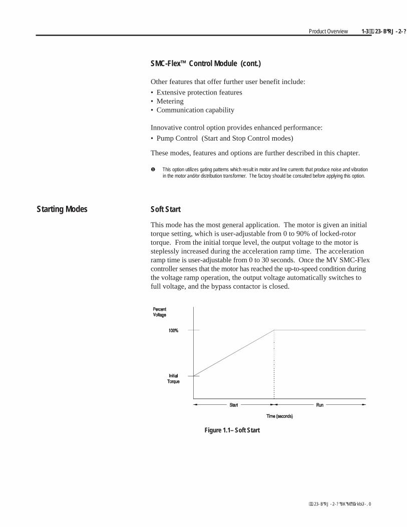
Starting Modes Soft Start
This mode has the most general application. The motor is given an initialtorque setting, which is user-adjustable from 0 to 90% of locked-rotortorque. From the initial torque level, the output voltage to the motor issteplessly increased during the acceleration ramp time. The accelerationramp time is user-adjustable from 0 to 30 seconds. Once the MV SMC-Flexcontroller senses that the motor has reached the up-to-speed condition duringthe voltage ramp operation, the output voltage automatically switches tofull voltage, and the bypass contactor is closed.
Figure 1.1– Soft Start
1-4 Product Overview
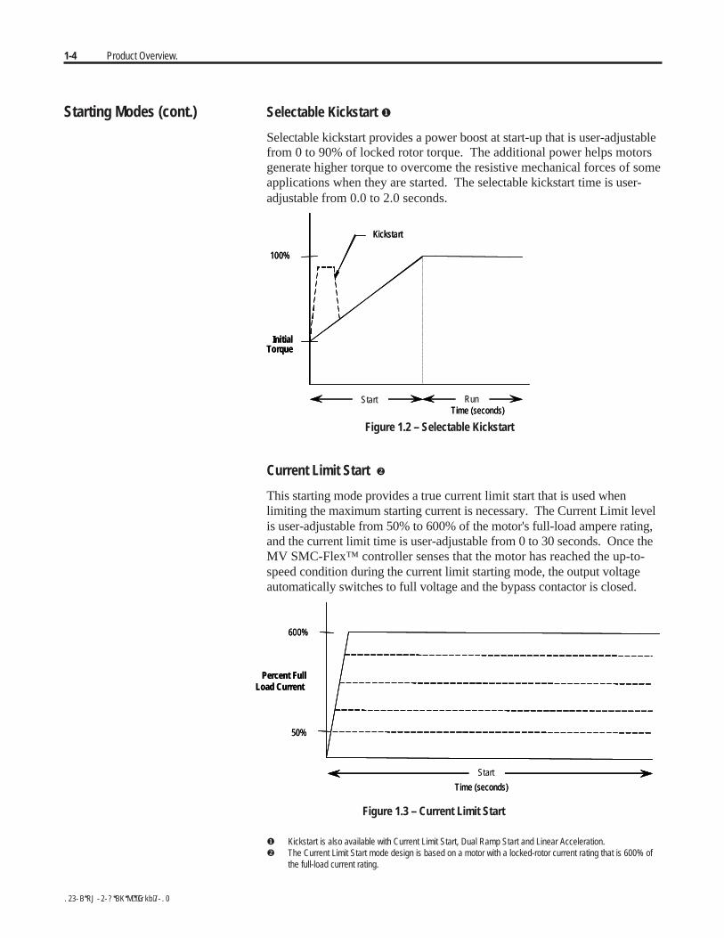
Starting Modes (cont.) Selectable Kickstart
Selectable kickstart provides a power boost at start-up that is user-adjustablefrom 0 to 90% of locked rotor torque. The additional power helps motorsgenerate higher torque to overcome the resistive mechanical forces of someapplications when they are started. The selectable kickstart time is user-adjustable from 0.0 to 2.0 seconds.
InitialTorque
Time (seconds)Start Run
100%
Kickstart
InitialTorque
Time (seconds)Start Run
100%
Kickstart
Figure 1.2 – Selectable Kickstart
Current Limit Start
This starting mode provides a true current limit start that is used whenlimiting the maximum starting current is necessary. The Current Limit levelis user-adjustable from 50% to 600% of the motor's full-load ampere rating,and the current limit time is user-adjustable from 0 to 30 seconds. Once theMV SMC-Flex™ controller senses that the motor has reached the up-to-speed condition during the current limit starting mode, the output voltageautomatically switches to full voltage and the bypass contactor is closed.
600%
50%
Percent FullLoad Current
Time (seconds)
Start
600%
50%
Percent FullLoad Current
Time (seconds)
Start
Figure 1.3 – Current Limit Start
Kickstart is also available with Current Limit Start, Dual Ramp Start and Linear Acceleration. The Current Limit Start mode design is based on a motor with a locked-rotor current rating that is 600% of
the full-load current rating.
Product Overview 1-5
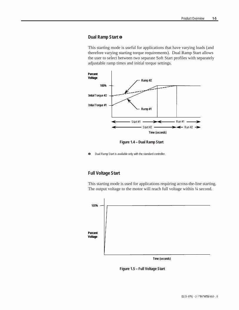
Dual Ramp Start
This starting mode is useful for applications that have varying loads (andtherefore varying starting torque requirements). Dual Ramp Start allowsthe user to select between two separate Soft Start profiles with separatelyadjustable ramp times and initial torque settings.
PercentVoltage
Initial Torque #1
100%
Ramp #2
Ramp #1
Time (seconds)
Initial Torque #2
Run #2Start #2
Start #1 Run #1
PercentVoltage
Initial Torque #1
100%
Ramp #2
Ramp #1
Time (seconds)
Initial Torque #2
Run #2Start #2
Start #1 Run #1
Figure 1.4 – Dual Ramp Start
Dual Ramp Start is available only with the standard controller.
Full Voltage Start
This starting mode is used for applications requiring across-the-line starting.The output voltage to the motor will reach full voltage within ¼ second.
100%
PercentVoltage
Time (seconds)
100%
PercentVoltage
Time (seconds)
Figure 1.5 – Full Voltage Start

1-6 Product Overview
Starting Modes (cont.) Preset Slow Speed
This option can be used in applications that require a slow-speed jog forgeneral purpose positioning. Preset Slow Speed provides either 7% ofbase speed (low) or 15% of base speed (high) settings in the forwarddirection. Reverse can also be programmed and offers 10% of base speed(low) and 20% of base speed (high) settings.
Run
Forward15% – High
7% – Low
10% – Low
20% – HighReverse
Time (seconds)Start RunRun
Forward15% – High
7% – Low
10% – Low
20% – HighReverse
Time (seconds)Start
Forward15% – High
7% – Low
10% – Low
20% – HighReverse
Time (seconds)Start
Figure 1.6 – Preset Slow Speed Option
Important: Slow speed running is not intended for continuous operation dueto reduced motor cooling. The two starts per hour limitation also applies toslow speed operation. This option employs a cycle-skipping scheme whichproduces limited torque. Applications should be checked with the factory.
Product Overview 1-7
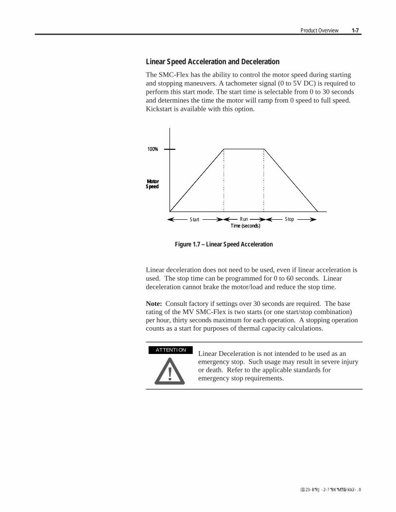
Linear Speed Acceleration and Deceleration
The SMC-Flex has the ability to control the motor speed during startingand stopping maneuvers. A tachometer signal (0 to 5V DC) is required toperform this start mode. The start time is selectable from 0 to 30 secondsand determines the time the motor will ramp from 0 speed to full speed.Kickstart is available with this option.
MotorSpeed
100%
Time (seconds)Start Run Stop
MotorSpeed
100%
Time (seconds)Start Run Stop
Figure 1.7 – Linear Speed Acceleration
Linear deceleration does not need to be used, even if linear acceleration isused. The stop time can be programmed for 0 to 60 seconds. Lineardeceleration cannot brake the motor/load and reduce the stop time.
Note: Consult factory if settings over 30 seconds are required. The baserating of the MV SMC-Flex is two starts (or one start/stop combination)per hour, thirty seconds maximum for each operation. A stopping operationcounts as a start for purposes of thermal capacity calculations.
Linear Deceleration is not intended to be used as anemergency stop. Such usage may result in severe injuryor death. Refer to the applicable standards foremergency stop requirements.
A T T E N T I O NA T T E N T I O N
1-8 Product Overview
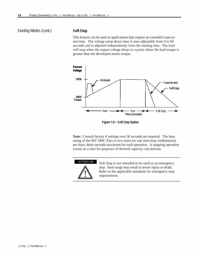
Starting Modes (cont.) Soft Stop
This feature can be used in applications that require an extended coast-to-rest time. The voltage ramp-down time is user-adjustable from 0 to 60seconds and is adjusted independently from the starting time. The loadwill stop when the output voltage drops to a point where the load torque isgreater than the developed motor torque.
Coast-to-rest
Soft Stop
Kickstart
InitialTorque
100%
PercentVoltage
Time (seconds)Start Run Soft Stop
Coast-to-rest
Soft Stop
Kickstart
InitialTorque
100%
PercentVoltage
Time (seconds)Start Run Soft Stop
Figure 1.8 – Soft Stop Option
Note: Consult factory if settings over 30 seconds are required. The baserating of the MV SMC-Flex is two starts (or one start/stop combination)per hour, thirty seconds maximum for each operation. A stopping operationcounts as a start for purposes of thermal capacity calculations.
Soft Stop is not intended to be used as an emergencystop. Such usage may result in severe injury or death.Refer to the applicable standards for emergency stoprequirements.
A T T E N T I O NA T T E N T I O N

Product Overview 1-9
Protection and Diagnostics The MV SMC-Flex™ controller is capable of providing the followingprotective and diagnostic features:
Overload
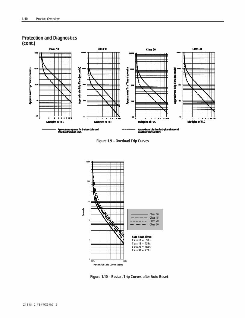
The MV SMC-Flex controller meets applicable requirements as a motoroverload protection device. Thermal memory provides added protectionand is maintained even when control power is removed. The built-inoverload algorithm controls the value stored in Parameter 12, MotorThermal Usage (see Chapter 4, Programming). An Overload Fault willoccur when this value reaches 100%. The parameters below provideapplication flexibility and easy setup.
Parameter Range
Overload Class Off, 10, 15, 20, 30Overload Reset Manual – Auto
Motor FLC 1.0 – 1000.0 ampsService Factor 0.01 – 1.99
Important: During slow speed operations, current waveforms exhibitnon-sinusoidal characteristics. These non-sinusoidal characteristicsinhibit the controller's current-measurement capability. To compensatefor additional motor heating that may result, the controller uses motorthermal modeling, which increments motor thermal usage. This compen-sation takes place when the Preset Slow Speed option is used.
Notes:1. The factory default setting for Overload Class, which is "OFF", disables
overload protection. An overload trip class and the motor's full-loadcurrent rating must be programmed to enable overload protection.
2. If the MV SMC-Flex is used to control a multi-speed motor, or morethan one motor, the Overload Class parameter must be programmedto "OFF" and separate overload relays must be supplied for eachspeed/motor.
3. Automatic reset of an overload fault requires the start input to becycled in a 2-wire control scheme.
4. The trip rating is 117% of the programmed FLC.
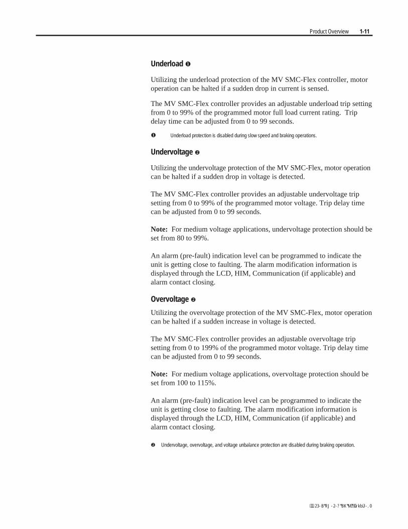
Figures 1.9 and 1.10 provide the overload trip curves for the available tripclasses.
1-10 Product Overview
Approximate trip time for 3-phase balancedcondition from cold start.
Approximate trip time for 3-phase balancedcondition from hot start.
Class 10 Class 15 Class 20 Class 30
Multiples of FLC Multiples of FLC Multiples of FLC Multiples of FLC
Appr
oxim
ate
Trip
Tim
e(s
econ
ds)
Appr
oxim
ate
Trip
Tim
e(s
econ
ds)
Appr
oxim
ate
Trip
Tim
e(s
econ
ds)
Appr
oxim
ate
Trip
Tim
e(s
econ
ds)
1.0
10.0
100.0
1000.0
10000.0
1 102 3 987654
0.1
1.0
10.0
100.0
1000.0
1 102 3 9876541.0
10.0
100.0
1000.0
10000.0
1 102 3 9876541.0
10.0
100.0
1000.0
10000.0
1 102 3 987654
Figure 1.9 – Overload Trip Curves
100000
1000
100
10
1
0100% 1000%
Percent Full Load Current Setting
Auto Reset Times:Class 10 = 90 sClass 15 = 135 sClass 20 = 180 sClass 30 = 270 s
Class 10Class 15Class 20Class 30
Seco
nda
100000
1000
100
10
1
0100% 1000%
Percent Full Load Current Setting
Auto Reset Times:Class 10 = 90 sClass 15 = 135 sClass 20 = 180 sClass 30 = 270 s
Class 10Class 15Class 20Class 30
Class 10Class 15Class 20Class 30
Seco
nda
Figure 1.10 – Restart Trip Curves after Auto Reset
Protection and Diagnostics(cont.)
Product Overview 1-11
Underload
Utilizing the underload protection of the MV SMC-Flex controller, motoroperation can be halted if a sudden drop in current is sensed.
The MV SMC-Flex controller provides an adjustable underload trip settingfrom 0 to 99% of the programmed motor full load current rating. Tripdelay time can be adjusted from 0 to 99 seconds.
Underload protection is disabled during slow speed and braking operations.
Undervoltage
Utilizing the undervoltage protection of the MV SMC-Flex, motor operationcan be halted if a sudden drop in voltage is detected.
The MV SMC-Flex controller provides an adjustable undervoltage tripsetting from 0 to 99% of the programmed motor voltage. Trip delay timecan be adjusted from 0 to 99 seconds.
Note: For medium voltage applications, undervoltage protection should beset from 80 to 99%.
An alarm (pre-fault) indication level can be programmed to indicate theunit is getting close to faulting. The alarm modification information isdisplayed through the LCD, HIM, Communication (if applicable) andalarm contact closing.
Overvoltage
Utilizing the overvoltage protection of the MV SMC-Flex, motor operationcan be halted if a sudden increase in voltage is detected.
The MV SMC-Flex controller provides an adjustable overvoltage tripsetting from 0 to 199% of the programmed motor voltage. Trip delay timecan be adjusted from 0 to 99 seconds.
Note: For medium voltage applications, overvoltage protection should beset from 100 to 115%.
An alarm (pre-fault) indication level can be programmed to indicate theunit is getting close to faulting. The alarm modification information isdisplayed through the LCD, HIM, Communication (if applicable) andalarm contact closing.
Undervoltage, overvoltage, and voltage unbalance protection are disabled during braking operation.
1-12 Product Overview
Unbalance
The MV SMC-Flex is able to detect an unbalance in line voltages. Motoroperation can be halted if the unbalance is greater than the desired range.
The MV SMC-Flex controller provides an adjustable unbalance settingfrom 0 to 25% of the line voltages. Trip delay time can be adjusted from 0to 99 seconds.
An alarm (pre-fault) indication level can be programmed to indicate theunit is getting close to faulting. The alarm modification information isdisplayed through the LCD, HIM, Communication (if applicable) andalarm contact closing.Undervoltage, overvoltage, and voltage unbalance protection are disabled during braking operation.
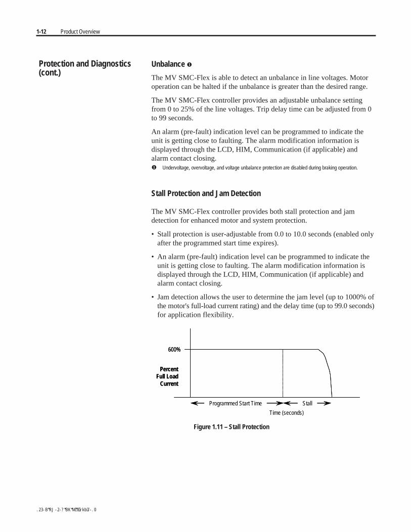
Stall Protection and Jam Detection
The MV SMC-Flex controller provides both stall protection and jamdetection for enhanced motor and system protection.
• Stall protection is user-adjustable from 0.0 to 10.0 seconds (enabled onlyafter the programmed start time expires).
• An alarm (pre-fault) indication level can be programmed to indicate theunit is getting close to faulting. The alarm modification information isdisplayed through the LCD, HIM, Communication (if applicable) andalarm contact closing.
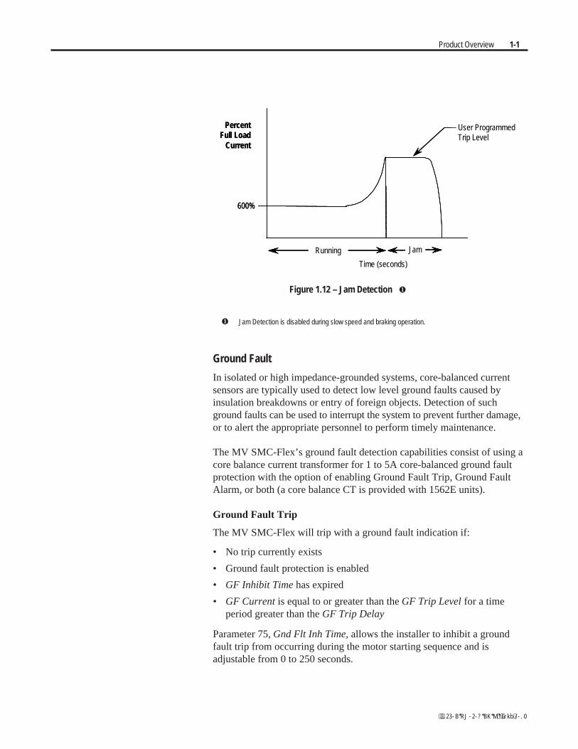
• Jam detection allows the user to determine the jam level (up to 1000% ofthe motor's full-load current rating) and the delay time (up to 99.0 seconds)for application flexibility.
600%
PercentFull Load
Current
Programmed Start Time Stall
Time (seconds)
600%
PercentFull Load
Current
Programmed Start Time Stall
Time (seconds)
Figure 1.11 – Stall Protection
Protection and Diagnostics(cont.)
Product Overview 1-1
600%
PercentFull Load
Current
Jam
Time (seconds)
Running
User ProgrammedTrip Level
600%
PercentFull Load
Current
Jam
Time (seconds)
Running
User ProgrammedTrip Level
Figure 1.12 – Jam Detection
Jam Detection is disabled during slow speed and braking operation.
Ground Fault
In isolated or high impedance-grounded systems, core-balanced currentsensors are typically used to detect low level ground faults caused byinsulation breakdowns or entry of foreign objects. Detection of suchground faults can be used to interrupt the system to prevent further damage,or to alert the appropriate personnel to perform timely maintenance.
The MV SMC-Flex’s ground fault detection capabilities consist of using acore balance current transformer for 1 to 5A core-balanced ground faultprotection with the option of enabling Ground Fault Trip, Ground FaultAlarm, or both (a core balance CT is provided with 1562E units).
Ground Fault Trip
The MV SMC-Flex will trip with a ground fault indication if:
• No trip currently exists
• Ground fault protection is enabled
• GF Inhibit Time has expired
• GF Current is equal to or greater than the GF Trip Level for a timeperiod greater than the GF Trip Delay
Parameter 75, Gnd Flt Inh Time, allows the installer to inhibit a groundfault trip from occurring during the motor starting sequence and isadjustable from 0 to 250 seconds.
1-14 Product Overview
Ground Fault Trip (cont.)
Parameter 74, Gnd Flt Delay, allows the installer to define the time perioda ground fault condition must be present before a trip occurs. It isadjustable from 0.1 to 25 seconds.
Parameter 73, Gnd Flt Level, allows the installer to define the groundfault current at which the MV SMC-Flex will trip. It is adjustable from1.0 to 5.0 A.
Important: The ground fault inhibit timer starts after the maximum phaseof load current transitions from 0 A to 30% of the device’s minimum FLASetting or the GF Current is greater than or equal to 0.5 A. The MVSMC-Flex does not begin monitoring for a ground fault condition until theGnd Flt Inh Time expires.
Ground Fault Alarm
The MV SMC-Flex will indicate a Ground Fault Alarm if:
• No warning currently exists
• Ground fault alarm is enabled
• GF Inhibit Time has expired
• GF Current is equal to or greater than the Gnd Flt A Lvl
Parameter 77, Gnd Flt A Lvl, allows the installer to define the ground faultcurrent at which an alarm will be indicated. It is adjustable from 1.0 to 5.0 A.
Parameter 78, Gnd Flt A Dly, allows the installer to define the time perioda ground fault alarm condition must be present before a trip occurs. It isadjustable from 0.1 to 25 seconds.
Thermistor/PTC Protection
The MV SMC-Flex provides terminals 23 and 24 for the connection ofpositive temperature coefficient (PTC) thermistor sensors. PTC sensors arecommonly embedded in motor stator windings to monitor the motorwinding temperature. When the motor winding temperature reaches thePTC sensor’s temperature rating, the PTC sensor’s resistance transitionsfrom a low to high value. Since PTC sensors react to actual temperature,enhanced motor protection can be provided to address such conditions asobstructed cooling and high ambient temperatures.
The following table defines the MV SMC-Flex PTC thermistor input andresponse ratings:
Protection and Diagnostics(cont.)
Product Overview 1-15
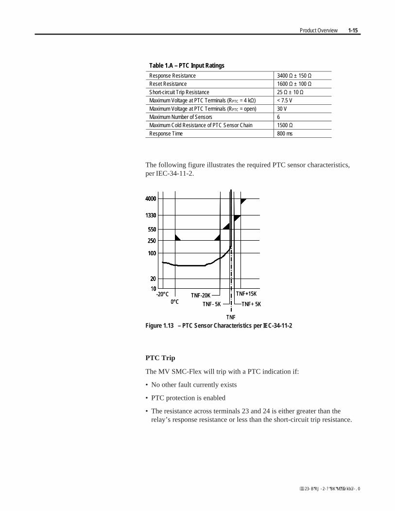
Table 1.A – PTC Input Ratings
Response Resistance 3400 Ω ± 150 ΩReset Resistance 1600 Ω ± 100 ΩShort-circuit Trip Resistance 25 Ω ± 10 ΩMaximum Voltage at PTC Terminals (RPTC = 4 kΩ) < 7.5 VMaximum Voltage at PTC Terminals (RPTC = open) 30 VMaximum Number of Sensors 6Maximum Cold Resistance of PTC Sensor Chain 1500 ΩResponse Time 800 ms
The following figure illustrates the required PTC sensor characteristics,per IEC-34-11-2.
10
20
4000
250
100
550
1330
TNF-20K
TNF- 5K
-20°C0°C
TNF
TNF+ 5K
TNF+15K10
20
4000
250
100
550
1330
10
20
4000
250
100
550
1330
10
20
4000
250
100
550
1330
TNF-20K
TNF- 5K
-20°C0°C
TNF
TNF+ 5K
TNF+15K
Figure 1.13 – PTC Sensor Characteristics per IEC-34-11-2
PTC Trip
The MV SMC-Flex will trip with a PTC indication if:
• No other fault currently exists
• PTC protection is enabled
• The resistance across terminals 23 and 24 is either greater than therelay’s response resistance or less than the short-circuit trip resistance.
1-16 Product Overview
Open Gate
An open-gate fault indicates that improper SCR firing, typically caused byan open SCR gate or driver system, has been detected on one of the powerpoles. Before the controller shuts down, it will attempt to start the motor atotal of three times (or as programmed in Parameter 82).
An open gate is detected when the module sends a gate signal to the SCRsbut does not detect that they turned on. SCR turn-on is detected when thevoltage across the leg (L-T) collapses.
Line Faults
The MV SMC-Flex™ controller continually monitors line conditions forabnormal factors. Pre-start protection includes:
• Line Fault (with phase indication)– Line voltage loss– Missing load connection– Shorted SCR
Running protection includes:
• Line Fault (no phase indication)– Line voltage loss– Missing load connection
Phase reversal protection can be toggled either ON or OFF.
Phase reversal protection is functional only at pre-start.
Protection and Diagnostics(cont.)
Product Overview 1-17
Excessive Starts/Hour
The MV SMC-Flex™ module allows the user to program the desirednumber of starts per hour (up to 99). This helps eliminate motor stresscaused by repeated starting over a short time period.
Note: The base rating of the MV SMC-Flex is two starts (thirty secondseach max.) per hour. Applications requiring more frequent starts, or longerduration starts, should be reviewed with the factory to avoid equipment damage.
Overtemperature
The power module temperature is monitored during starting and stoppingmaneuvers by thermistors. The thermistor is connected to the gate driverboard where it is processed, and the status is transmitted by fibre-opticcable through the interface board to the control module. When anovertemperature condition exists (>85°C), the control module trips andindicates a "PTC Power Pole" fault.
An overtemperature condition could indicate high ambient temperature,overloading or excessive cycling. After the power module temperature isreduced to allowable levels, the fault can be cleared (see page 9-1 forinstructions).
Metering Power monitoring parameters include:
• Three-phase current• Three-phase voltage• Power in MW• Power usage in MWh• Power factor• Motor thermal capacity usage• Elapsed time• Motor speed (100%, with use of optional tachometer input)
Notes:
1. Voltage measurement is not available during the braking operation ofthe SMB Smart Motor Braking, Accu-Stop, and Slow Speed withBraking control options.
2. The elapsed time and MWh values are automatically saved to memoryevery 12 hours.
3. Motor thermal capacity usage is determined by the built-in electronicthermal overload. An overload fault occurs when this value reaches100%.
1-18 Product Overview
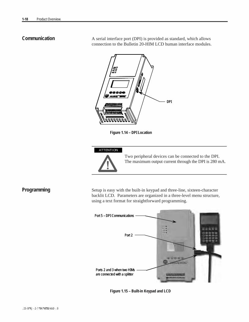
Communication A serial interface port (DPI) is provided as standard, which allowsconnection to the Bulletin 20-HIM LCD human interface modules.
DPIDPI
Figure 1.14 – DPI Location
Two peripheral devices can be connected to the DPI.The maximum output current through the DPI is 280 mA.
Programming Setup is easy with the built-in keypad and three-line, sixteen-characterbacklit LCD. Parameters are organized in a three-level menu structure,using a text format for straightforward programming.
Port 5 – DPI Communications
Port 2
Ports 2 and 3 when two HIMsare connected with a splitter
Port 5 – DPI Communications
Port 2
Ports 2 and 3 when two HIMsare connected with a splitter
Figure 1.15 – Built-in Keypad and LCD
A T T E N T I O NA T T E N T I O N

Product Overview 1-19
Status Indication Four programmable hard contact outputs are provided as standard:
• The Auxiliary #1 Contact is N.O. It is always programmed forUp-to-speed to control the bypass contactor in MV applications.
• The fault Contact is for fault indication and is programmable for N.O./N.C.
• The alarm Contact is for alarm indication and is programmable for N.O./N.C.
• The Auxiliary #2 Contact is for normal indication and is programmablefor N.O./N.C. For MV applications, it is configured as N.O. to controlthe line contactor.
11 12 13 14 15 16 17 18 19 20 21 22
SMC-FlexControl Terminals
Aux #1Up-to-Speed
23 24 25 26 27 28 29 30 31 32 33 34
PTCInput
TACHInput
GroundFault
FaultContact
AlarmContact
Aux #2Normal
11 12 13 14 15 16 17 18 19 20 21 22
SMC-FlexControl Terminals
Aux #1Up-to-Speed
23 24 25 26 27 28 29 30 31 32 33 34
PTCInput
TACHInput
GroundFault
FaultContact
AlarmContact
Aux #2Normal
Figure 1.16 – Control Terminals
Control Options The MV SMC-Flex™ controller offers the control options described below.
Important: The options listed in this section are mutually exclusive andmust be specified when ordering. An existing controller may be upgradedto another control option by replacing the control module and possibly othercomponents. Consult your nearest Rockwell Automation sales office.
Pump Control Option
This option reduces surges during the starting and stopping of a centrifugalpump by smoothly accelerating and decelerating the motor. The micro-processor analyzes the motor variables and generates commands that controlthe motor and reduce the possibility of surges occurring in the system.
The motor current will vary during the acceleration period, and may benear the motor rated starting current. The pump algorithm does not limitstarting current since full voltage is needed to reach full speed with aloaded motor.
The starting time is programmable from 0-30 seconds, and the stoppingtime is programmable from 0-120 seconds.
1-20 Product Overview
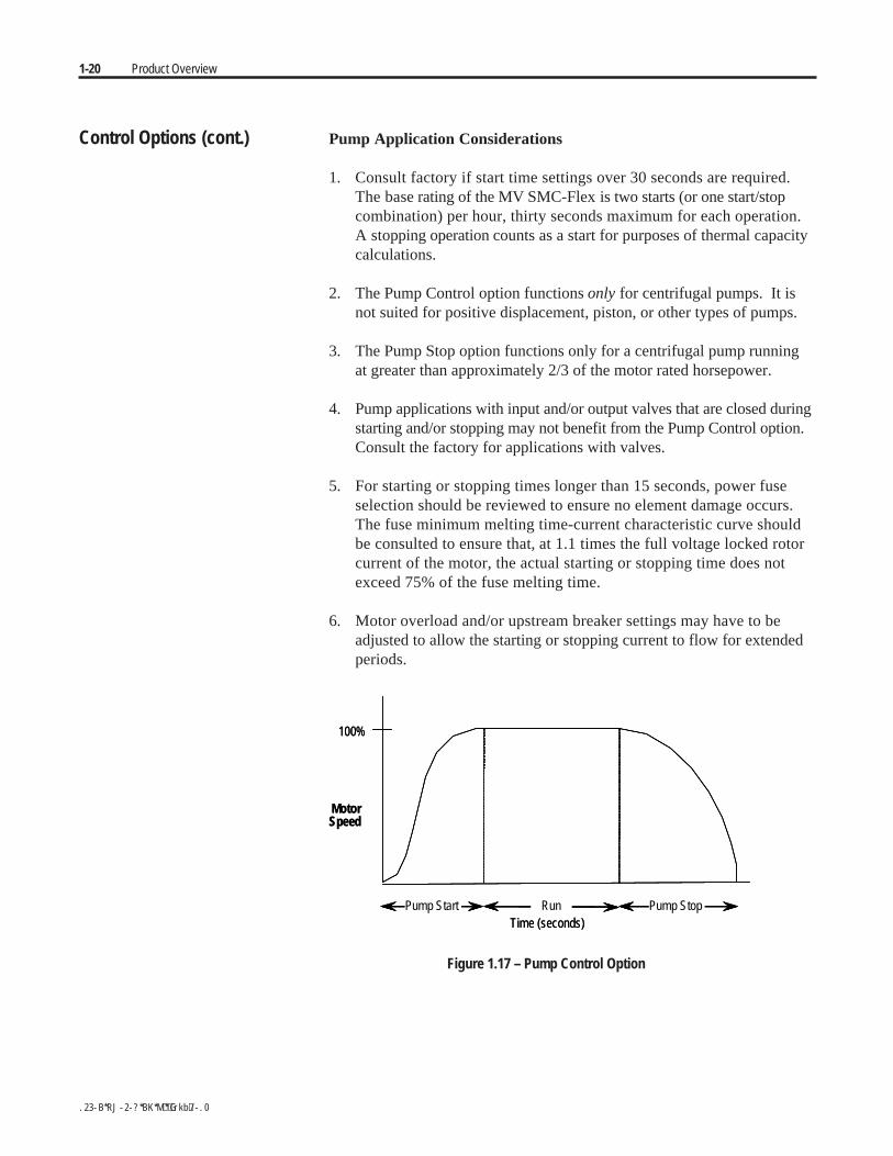
Control Options (cont.) Pump Application Considerations
1. Consult factory if start time settings over 30 seconds are required.The base rating of the MV SMC-Flex is two starts (or one start/stopcombination) per hour, thirty seconds maximum for each operation.A stopping operation counts as a start for purposes of thermal capacitycalculations.
2. The Pump Control option functions only for centrifugal pumps. It isnot suited for positive displacement, piston, or other types of pumps.
3. The Pump Stop option functions only for a centrifugal pump runningat greater than approximately 2/3 of the motor rated horsepower.
4. Pump applications with input and/or output valves that are closed duringstarting and/or stopping may not benefit from the Pump Control option.Consult the factory for applications with valves.
5. For starting or stopping times longer than 15 seconds, power fuseselection should be reviewed to ensure no element damage occurs.The fuse minimum melting time-current characteristic curve shouldbe consulted to ensure that, at 1.1 times the full voltage locked rotorcurrent of the motor, the actual starting or stopping time does notexceed 75% of the fuse melting time.
6. Motor overload and/or upstream breaker settings may have to beadjusted to allow the starting or stopping current to flow for extendedperiods.
MotorSpeed
100%
Time (seconds)Pump Start Run Pump Stop
MotorSpeed
100%
Time (seconds)Pump Start Run Pump Stop
Figure 1.17 – Pump Control Option
Product Overview 1-21
Pump stopping is not intended to be used as anemergency stop. Refer to the applicable standard foremergency stop requirements.
Pump stopping may cause motor heating depending onthe mechanical dynamics of the pumping system.Therefore, select the lowest stopping time setting thatwill satisfactorily stop the pump.
Braking Control Option
The Braking Control option (Smart Motor Braking, Accu-Stop and SlowSpeed with Braking) are not offered for standard use in MV applications.Please consult factory for further assistance.
A T T E N T I O NA T T E N T I O N
A T T E N T I O NA T T E N T I O N
1-22 Product Overview
Hardware Description The following sections contain descriptions of system components andsystem operation. Each section will be described to give the user anunderstanding of the MV SMC-Flex to facilitate operation and maintenanceof the system. Refer to Figures 1.18 through 1.21, Typical MV SMC-FlexPower System.
Power Module
The controller consists of three power modules, one for each phase. Eachpower module consists of incoming and outgoing terminals for cables, SCRs,heatsink and clamp assembly. The SCRs are connected in inverse parallel(and in series for 12- or 18-SCR assemblies) to form a three-phase, ACline controller configuration.
Each power module includes a snubber circuit to limit the rate of rise involtage across each SCR pair. The module also includes patented gatedriver circuits which derive their power from the snubber circuit.
Voltage sharing resistors are connected across each SCR pair to providestatic voltage balance for series-connected SCRs. These resistors aretapped to provide a reference for overvoltage protection circuitry on thegate driver board.
A voltage sensing board is used to reduce the line-side and load-side voltagesto lower levels that can be measured by the SMC-Flex control module.
Self-Powered Silicon-Controlled Rectifier Gate Driver Board
This board provides the turn-on capability for SCR devices. The boardalso provides optical fibre isolation between itself and the gating sourcelogic. It is powered by recovering energy from the snubber circuit, so it isfully isolated from the control and logic circuits; it is self-economizingwhen the unit is not running, or is in bypass mode.
Note: If pump control or stop control are used, the gate driver boards arepowered continuously using separate power supply boards. (Refer toChapter 8 for additional details.)
The MV SMC-Flex has three heatsinks fitted with a thermistor to monitortemperature rise. The circuitry on the gate driver board accepts thethermistor, and drives a fibre-optic cable if the temperature is below thesetpoint (85°C). If the temperature rises above the setpoint, the driver isturned off, and the MV SMC-Flex is signalled to stop gating and initiate atemperature fault.
Due to the self-powered nature of the circuits, this function is active onlywhile the SMC is active. While the starter is off, or in bypass, no power isdissipated in the SCRs and the temperature of the SCRs can only decrease.

Product Overview 1-23
Interface Board
This circuit board takes current transformer signals plus line-side and load-side voltage feedback signals from the voltage sensing board and passesthem to the SMC-Flex for processing. The control module produces gatingsignals for the SCRs, which are received on the interface board, and usedto drive fibre-optic transmitters. The gating signals are sent to the gate-drivercircuit board via fibre-optic cables. The interface board also receivestemperature feedback from the gate-driver board via fibre-optic cable(s).If the heatsink temperature rises above a set value, a signal is sent to theSMC-Flex to stop gating the SCRs and initiate a temperature fault.
For a detailed layout of this circuit board, refer to Figure 3.2 on page 3-6.

1-24 Product Overview
Figure 1.18 – Typical MV SMC-Flex Power System • Bulletin 1562E (Without Stop Control)
*
Product Overview 1-25
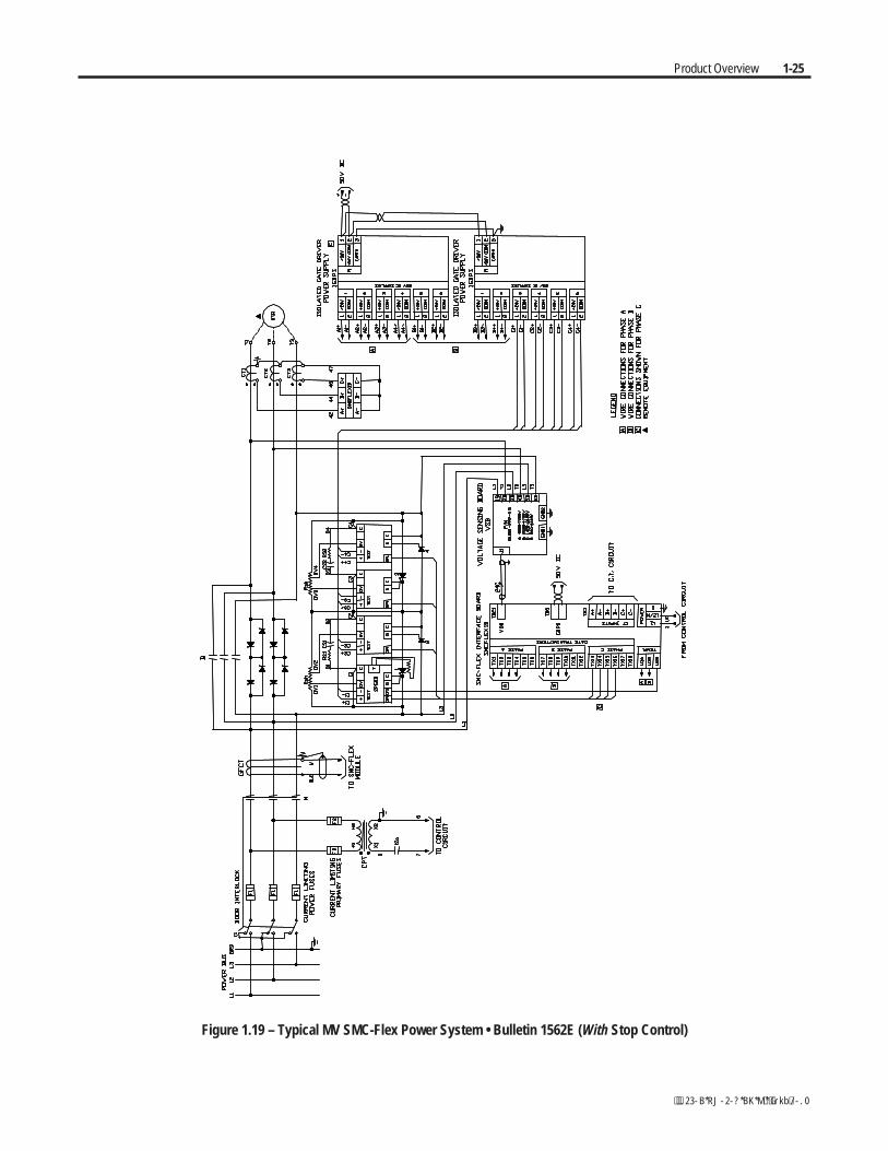
Figure 1.19 – Typical MV SMC-Flex Power System • Bulletin 1562E (With Stop Control)

1-26 Product Overview
Figure 1.20 – Typical MV SMC-Flex Power System • Bulletin 1560E (Without Stop Control)
Product Overview 1-27
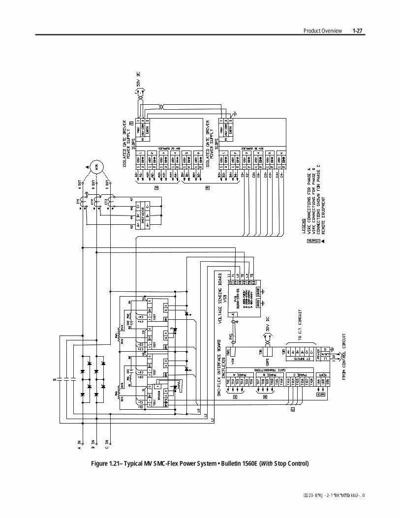
Figure 1.21– Typical MV SMC-Flex Power System • Bulletin 1560E (With Stop Control)

1-28 Product Overview
Functional Description The following functional descriptions and associated control circuits arefor units using IntelliVAC contactor control modules. For units withelectromechanical (relay) control, refer to Appendix C.
Bulletin 1562E • Basic Control – Controlled Start only
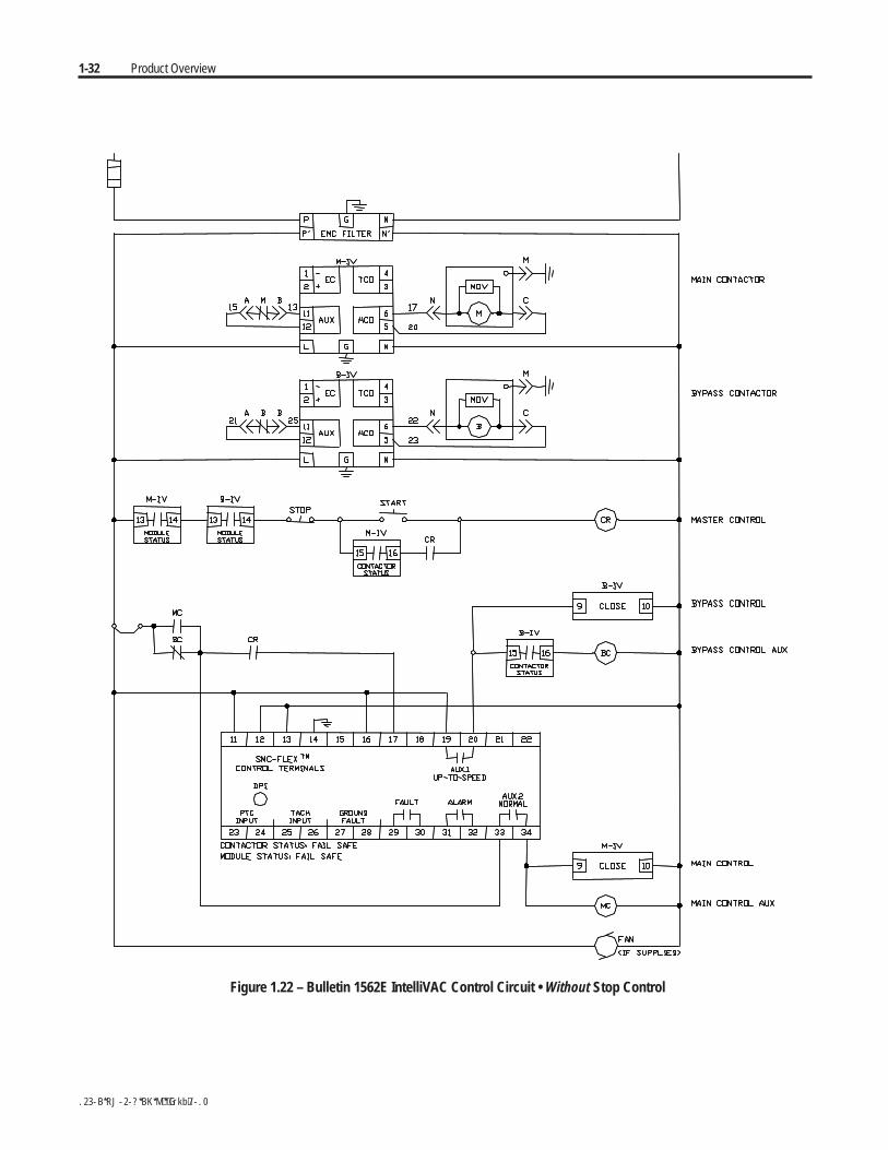
When wired as shown in Figure 1.22, the controller operates as follows:
Pressing the "Start" button initiates the start sequence. Relay "CR" closesand applies control power to terminal 17 of the SMC-Flex module. Theauxiliary contact #2 ("Normal") closes, energizing "M-IV" and "MC",which completes the hold-in circuit on the start button, and closes the maincontactor.
The SMC-Flex module examines the line voltage, looks for faultconditions, checks phase rotation, calculates zero crossing information, andbegins gating the SCRs to start the motor.
When the motor approaches rated speed, the SMC-Flex module closes the"AUX1" (up-to-speed) auxiliary contacts, energizing "B-IV", which closesthe bypass contactor. The motor then runs at full line voltage.
When the "Stop" button is pressed, the "CR" relay opens terminal 17 onthe SMC-Flex module. The "Normal" contact opens, dropping out themain contactor, allowing the motor to stop. The "AUX1" contact is heldclosed for a short time by the control module. This holds the bypasscontactor closed for about 10 seconds to protect the power electronics fromany voltage transients due to opening the motor circuits.
Product Overview 1-29
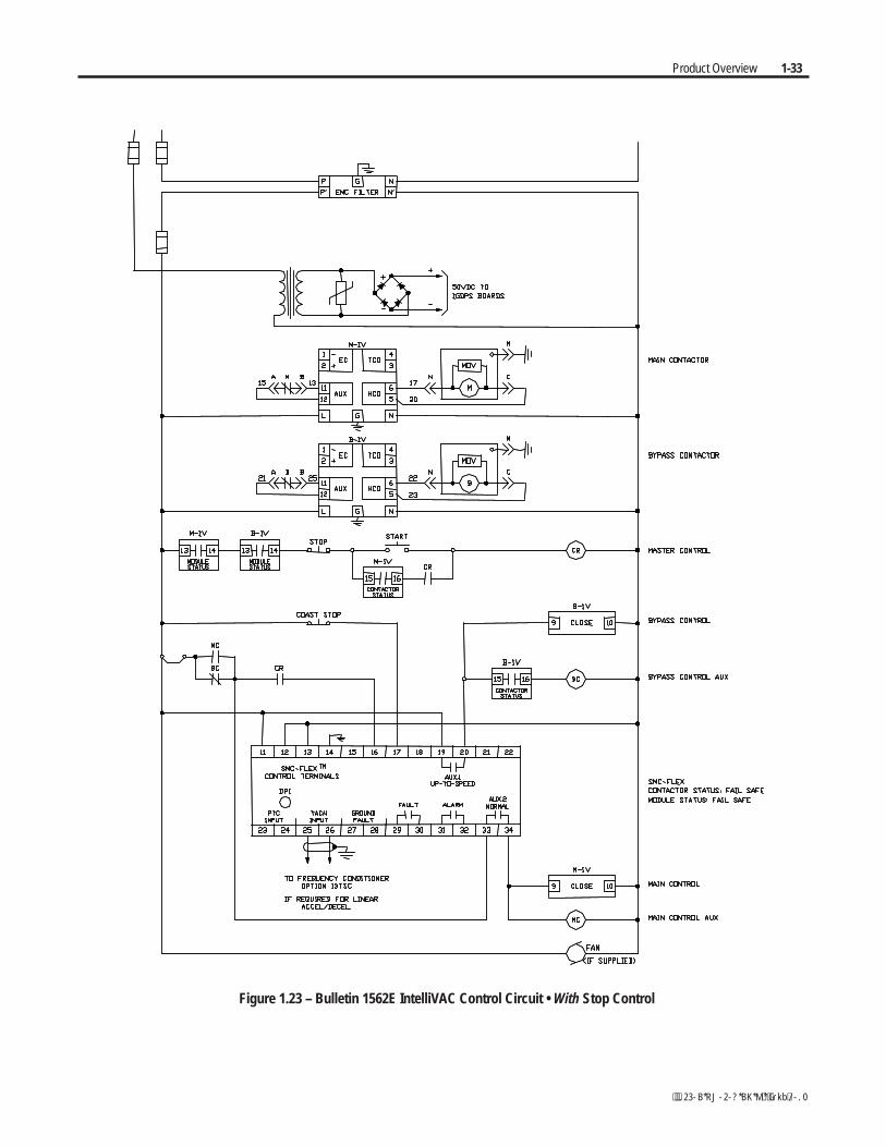
Bulletin 1562E • Basic Control – With Controlled Stop
When wired as shown in Figure 1.23, the controller operates in much thesame manner as in Figure 1.22.
Terminal 16 on the SMC-Flex module now controls the start and stopmaneuvers. Terminal 16 must remain energized for the module to run.When the “Stop” button is pressed, and “CR” opens, the SMC-Flex modulewill initiate the option stop. An uncontrolled, or coast stop, is achieved byopening the connection to terminal 17. This contact should remain open toensure all hold-in contacts clear, to prevent a re-start.
If the motor has started, the unit is in the bypass mode, and a trip occurswithin the SMC-Flex module or from an external protection relay; "AUX2"will open the line contactor immediately, and "AUX1" will remain closedfor 10 seconds. A trip due to an overload or fault condition will result in a“coast” stop.
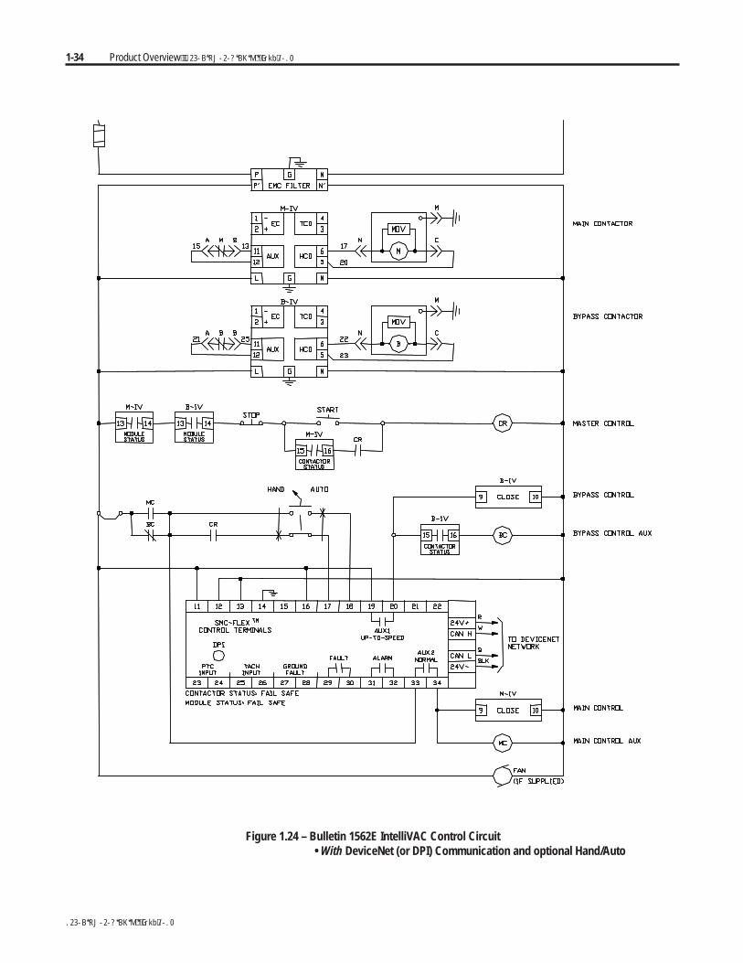
Bulletin 1562E • DPI Control – Controlled Start only
The control scheme shown in Figure 1.24 allows the MV SMC-Flex to becontrolled using DPI (Drive Programming Interface). This special usage ofDPI includes provisions for a "Hand" mode of control as well.
With the Hand-Auto selector switch in the "Auto" position, terminal 18 ofthe SMC-Flex module is energized, allowing a start command to beexecuted via DPI. The "AUX2" contact closes, energizing both "M-IV"and "MC".
When the motor approaches rated speed, the SMC-Flex module closes"AUX1", energizing "B-IV", which closes the bypass contactor.
To run in "Hand" mode, the "CR" contact is used to initiate a startsequence (similar to Figure 1.22).
A stop command can be generated via DPI or by opening "CR", dependingon the control mode.
1-30 Product Overview
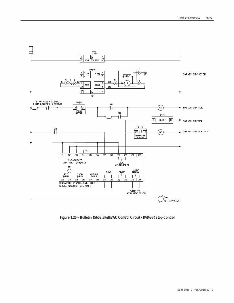
Functional Description (cont.) Bulletin 1560E • Basic Control – Controlled Start Only
The Bulletin 1560E is intended for addition to an existing motorcontroller, which provides circuit isolation, motor switching, andoverload and overcurrent protection. When wired as shown in Figure1.25, the controller operates as follows:
When a start is initiated in the existing motor controller and the contactor(or breaker) closes, a contact must be supplied to tell the 1560E to startalso. A "CR" contact will apply control voltage to terminal 17 of theSMC-Flex module.
When stopping the motor, the contactor in the existing controller willopen, removing power from the motor, and then the “CR” relay. Thebypass hold-in rung will keep the bypass contactor closed for a short time.
The “Fault” contact on the SMC-Flex module should be wired into theexisting controller to trip the main contactor (or breaker) in the event of afault condition sensed by the SMC-Flex module.
If possible, it is better to have the SMC-Flex module control the maincontactor directly. In this case, the control circuit would look like, andfunction like, the descriptions above for the Bulletin 1562E.
Bulletin 1560E • Basic control – With Controlled Stop
When wired as shown in Figure 1.26, the controller operates much thesame as described above for the Standard module. The control signal usesterminal 16 instead of 17, and a “coast” stop can be achieved by openingthe connection to terminal 17.
It is more important in this configuration to integrate the control circuit ofthe 1560E with the existing controller, for better control of the Stopoption. The “start signal” for this scheme cannot be a slave of the maincontactor, since it must remain closed to accomplish the option stopmaneuver. The SMC-Flex module can be used to control the maincontactor such that it will close when a start is initiated, and remain closeduntil it has sensed the motor has stopped following an option stopmaneuver.
Product Overview 1-31
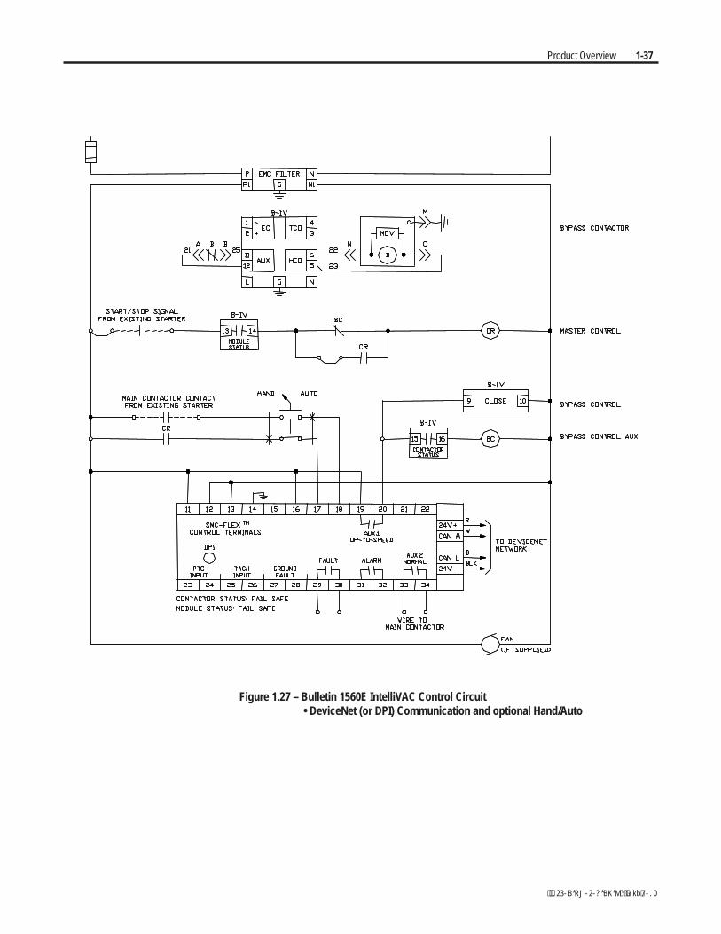
Bulletin 1560E • DPI Control – Controlled Start only
The control scheme shown in Figure 1.27 allows the MV SMC-Flex to becontrolled using DPI. This special usage of DPI includes provisions for a"Hand" mode of control as well.
With the Hand-Auto selector switch in the "Auto" position, and closure ofthe existing starter main contactor, terminal 18 is energized, allowing astart command to be executed via DPI. "AUX2" serves as an interlockwith the main contactor (or breaker) in the existing starter.
As with the other control schemes, the SMC-Flex module closes "AUX1",energizing "B-IV", as the motor approaches rated speed.
Hand control is enabled with the selector switch in the "Hand" position.Closure of the "Start" relay, from the existing starter, allows the unit toinitiate motor soft starting.
1-32 Product Overview
Figure 1.22 – Bulletin 1562E IntelliVAC Control Circuit • Without Stop Control
Product Overview 1-33
Figure 1.23 – Bulletin 1562E IntelliVAC Control Circuit • With Stop Control
1-34 Product Overview
Figure 1.24 – Bulletin 1562E IntelliVAC Control Circuit • With DeviceNet (or DPI) Communication and optional Hand/Auto
Product Overview 1-35
Figure 1.25 – Bulletin 1560E IntelliVAC Control Circuit • Without Stop Control

1-36 Product Overview
Figure 1.26 – Bulletin 1560E IntelliVAC Control Circuit • With Stop Control
Product Overview 1-37
Figure 1.27 – Bulletin 1560E IntelliVAC Control Circuit • DeviceNet (or DPI) Communication and optional Hand/Auto

1-38 Product Overview
Installation
Perform the installation duties correctly. Errors maycause commissioning delays, equipment damage orpersonal injury.
Important: For the 1503E, refer to applicable documentation from OEMinstallation, grounding, interlocking and wiring. This manual should beutilized in conjunction with the OEM supplied documentation, and issuitable for commissioning, programming, calibration, metering, serialcommunications, diagnostics, troubleshooting, and maintenance of astandard solid-state controller.
Receiving It is the responsibility of the user to thoroughly inspect the equipmentbefore accepting the shipment from the freight company. Check the item(s)received against the purchase order. If any items are damaged, it is theresponsibility of the user not to accept delivery until the freight agent hasnoted the damage on the freight bill. Should any concealed damage befound during unpacking, it is again the responsibility of the user to notifythe freight agent. The shipping container must be left intact and the freightagent should be requested to make a visual inspection of the equipment.
Safety and Codes The Canadian Electrical Code (CEC), National ElectricalCode (NEC), or other local codes outline provisions forsafely installing electrical equipment. InstallationMUST comply with specifications regarding wire type,conductor sizes, branch circuit protection, interlockingand disconnect devices. Failure to do so may result inpersonal injury and/or equipment damage.
Unpacking and Inspection After unpacking the material, check the item(s) received against the bill oflading to ensure that the nameplate description of each item agrees withthe material ordered. Inspect the equipment for physical damage, as statedin the Rockwell Automation Conditions of Sale.
Remove all packing material, wedges, or braces from within the controller.Operate the contactors and relays manually to ensure that they operate freely.Store the equipment in a clean, dry place if it will not be installed immediatelyafter unpacking. The storage temperature must be between -20°C and 75°C(-4°F and 167°F) with a maximum humidity of 95%, non-condensing, toguard against damage to temperature sensitive components in the controller.
Chapter 2
A T T E N T I O NA T T E N T I O N
A T T E N T I O NA T T E N T I O N
2-2 Installation
General Precautions In addition to the precautions listed throughout this manual, the followingstatements, which are general to the system, must be read and understood.
The controller contains ESD (electrostatic discharge)sensitive parts and assemblies. Static controlprecautions are required when installing testing,servicing, or repairing the assembly. Componentdamage may result if ESD control procedures are notfollowed. If you are not familiar with static controlprocedures, refer to applicable ESD protection handbooks.
An incorrectly applied or installed controller candamage components or reduce product life. Wiring orapplication errors, such as undersizing the motor,incorrect or inadequate AC supply, or excessive ambienttemperatures, may result in malfunction of the system.
Only personnel familiar with the controller and associatedmachinery should plan or implement the installation,start-up, and subsequent maintenance of the system.Failure to do this may result in personal injury and/orequipment damage.
Transportation and Handling The controller must be transported on a pallet or via use of the liftingangles supplied as part of all 90-inch (2.3 m) high cabinets or frame units.
Ensure that the load rating of the lifting device issufficient to safely raise the controller sections. Failureto do so may result in severe injury and/or equipmentdamage. Refer to the packing slip enclosed with shipmentfor shipping weights.
Round rollers can be used to assist in moving the controller to the instal-lation site. Once at the final site, the pipe rolling technique can be used toplace the cabinet in the desired position.
Care must be exercised when using either a forklift, orthe pipe rolling technique, for positioning purposes toensure that the equipment is not scratched, dented ordamaged in any manner. Always exercise care tostabilize the controller during handling to guard againsttipping and injury to personnel.
A T T E N T I O NA T T E N T I O N
A T T E N T I O NA T T E N T I O N
A T T E N T I O NA T T E N T I O N
A T T E N T I O NA T T E N T I O N
A T T E N T I O NA T T E N T I O N

Installation 2-3
Installation Site Consider the following when selecting the installation site:
A. The operating ambient temperature should be between 0°C and 40°C(32°F and 104°F) for NEMA Type 1 or 12 enclosures. For higherambient conditions, please consult Rockwell Automation factory.
B. The relative humidity must not exceed 95%, non-condensing. Excessivehumidity can cause electrical problems from corrosion or excessivedirt build-up.
C. The equipment must be kept clean. Dust build-up inside the enclosureinhibits proper cooling and decreases the system reliability. Theequipment should not be located where liquid or solid contaminants candrop onto it. Controllers with ventilated enclosures (in particular thosewith fans) must be in a room free of airborne contaminants.
D. Only persons familiar with the function of the controller should haveaccess to it.
E. The losses in the controller produce a definite heat dissipation,depending on the unit size, that tends to warm the air in the room.Attention must be given to the room ventilation and cooling require-ments to ensure that the proper environmental conditions are met.
F. Operational altitude is 3,300 feet (1 km) maximum without derating.Higher altitudes may require optional components. Please consultRockwell Automation factory.
G. The area of the controller should be free of radio frequency interferencesuch as encountered with some welding units. This may cause erroneousfault conditions and shut down the system.
An incorrectly applied or installed controller can result incomponent damage or a reduction in product life. Wiringor application errors, such as, undersizing the motor,incorrect or inadequate AC supply, or ambient tempera-tures above or below the specified temperature range mayresult in malfunction of the controller.
Mounting
The 1503E, 1560E and 1562E are designed to be mounted in the verticalposition. Standard cabinet drawings with certified dimension drawings canbe obtained by contacting your local Rockwell Automation Sales office forthe 1560E/1562E. Please refer to OEM documentation for the 1503E.Refer to drawings for mounting requirements.
A T T E N T I O NA T T E N T I O N
2-4 Installation
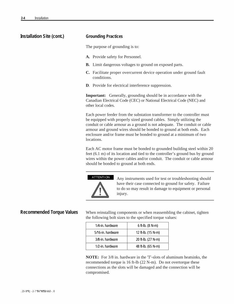
Installation Site (cont.) Grounding Practices
The purpose of grounding is to:
A. Provide safety for Personnel.
B. Limit dangerous voltages to ground on exposed parts.
C. Facilitate proper overcurrent device operation under ground faultconditions.
D. Provide for electrical interference suppression.
Important: Generally, grounding should be in accordance with theCanadian Electrical Code (CEC) or National Electrical Code (NEC) andother local codes.
Each power feeder from the substation transformer to the controller mustbe equipped with properly sized ground cables. Simply utilizing theconduit or cable armour as a ground is not adequate. The conduit or cablearmour and ground wires should be bonded to ground at both ends. Eachenclosure and/or frame must be bonded to ground at a minimum of twolocations.
Each AC motor frame must be bonded to grounded building steel within 20feet (6.1 m) of its location and tied to the controller’s ground bus by groundwires within the power cables and/or conduit. The conduit or cable armourshould be bonded to ground at both ends.
Any instruments used for test or troubleshooting shouldhave their case connected to ground for safety. Failureto do so may result in damage to equipment or personalinjury.
Recommended Torque Values When reinstalling components or when reassembling the cabinet, tightenthe following bolt sizes to the specified torque values:
1/4-in. hardware 6 ft-lb. (8 N-m)
5/16-in. hardware 12 ft-lb. (15 N-m)
3/8-in. hardware 20 ft-lb. (27 N-m)
1/2-in. hardware 48 ft-lb. (65 N-m)
NOTE: For 3/8 in. hardware in the 'T'-slots of aluminum heatsinks, therecommended torque is 16 ft-lb (22 N-m). Do not overtorque theseconnections as the slots will be damaged and the connection will becompromised.
A T T E N T I O NA T T E N T I O N
Installation 2-5
Power Connections The controller requires a three-phase supply and an equipment groundingconductor to earth ground. A neutral conductor of the three-phase supplyis not necessary and is usually not routed to the controller. Three-phasewiring will connect the controller to the motor.
Bulletin 1562E
The Bulletin 1562E unit is available in two main configurations:
1. A modified two-high cabinet (180/360A, 2400 to 4160 V)
2. A combination of a one-high full voltage non-reversing (FVNR)cabinet and a 1560E unit (600A, 2400 to 4160 V, and 180/360/600A,5500 to 6900 V)
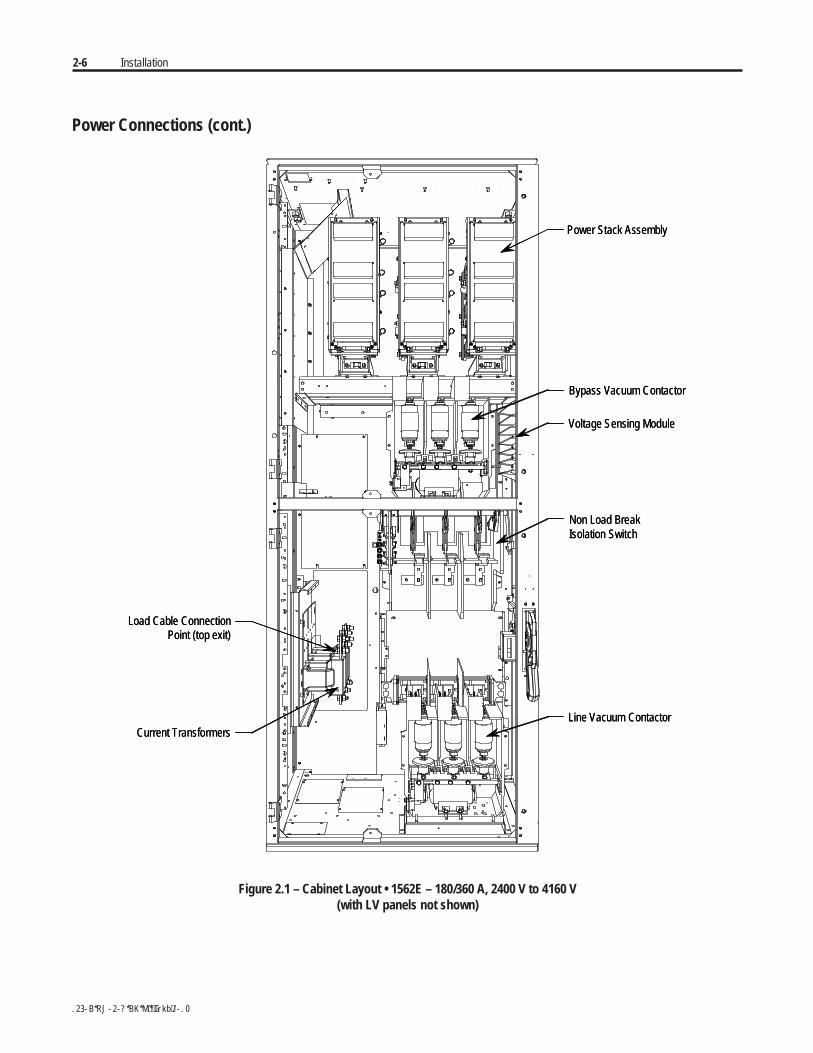
To make power connections for a two-high cabinet, refer to Figures 2.1 to2.3, and Publication 1500-UM055B-EN-P (Chapter 2).
To make power connections for a one-high FVNR cabinet and a 1560Eunit, proceed as follows:
• Make line connections within the one-high cabinet
• Make load connections at the 1560E CT terminals (refer to Figure 2.5 or2.6)
2-6 Installation
Power Connections (cont.)
Power Stack Assembly
Bypass Vacuum Contactor
Voltage Sensing Module
Non Load BreakIsolation Switch
Line Vacuum Contactor
Load Cable ConnectionPoint (top exit)
Current Transformers
Power Stack Assembly
Bypass Vacuum Contactor
Voltage Sensing Module
Non Load BreakIsolation Switch
Line Vacuum Contactor
Load Cable ConnectionPoint (top exit)
Current Transformers
Figure 2.1 – Cabinet Layout • 1562E – 180/360 A, 2400 V to 4160 V(with LV panels not shown)
Installation 2-7
Power Cable Lugs
Ground Bus Lug
Power Cable Lugs
Ground Bus Lug
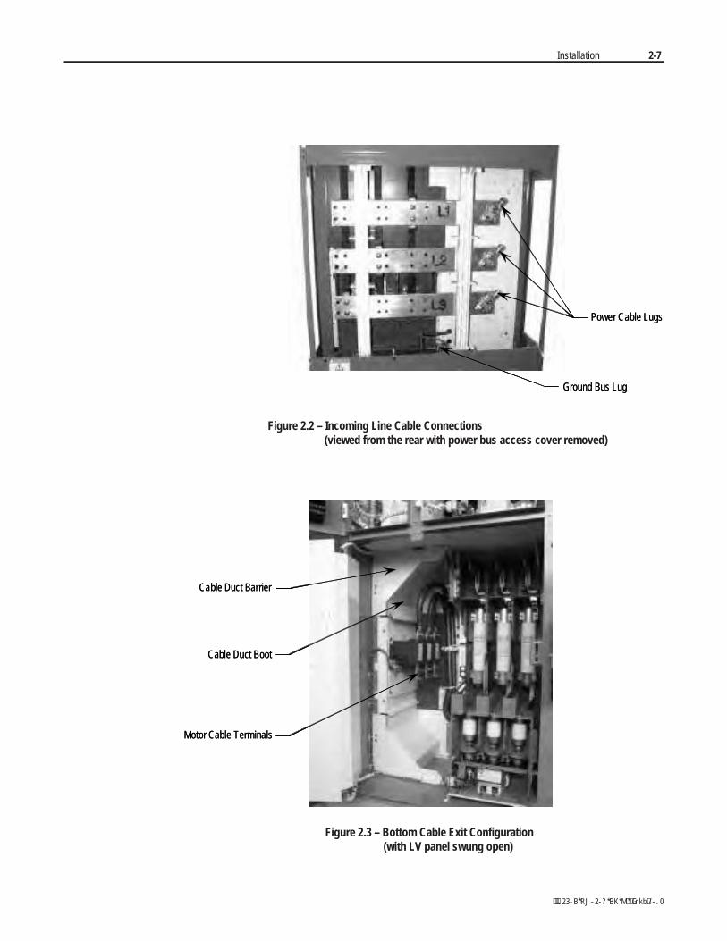
Figure 2.2 – Incoming Line Cable Connections (viewed from the rear with power bus access cover removed)
Cable Duct Barrier
Cable Duct Boot
Motor Cable Terminals
Cable Duct Barrier
Cable Duct Boot
Motor Cable Terminals
Figure 2.3 – Bottom Cable Exit Configuration (with LV panel swung open)
2-8 Installation
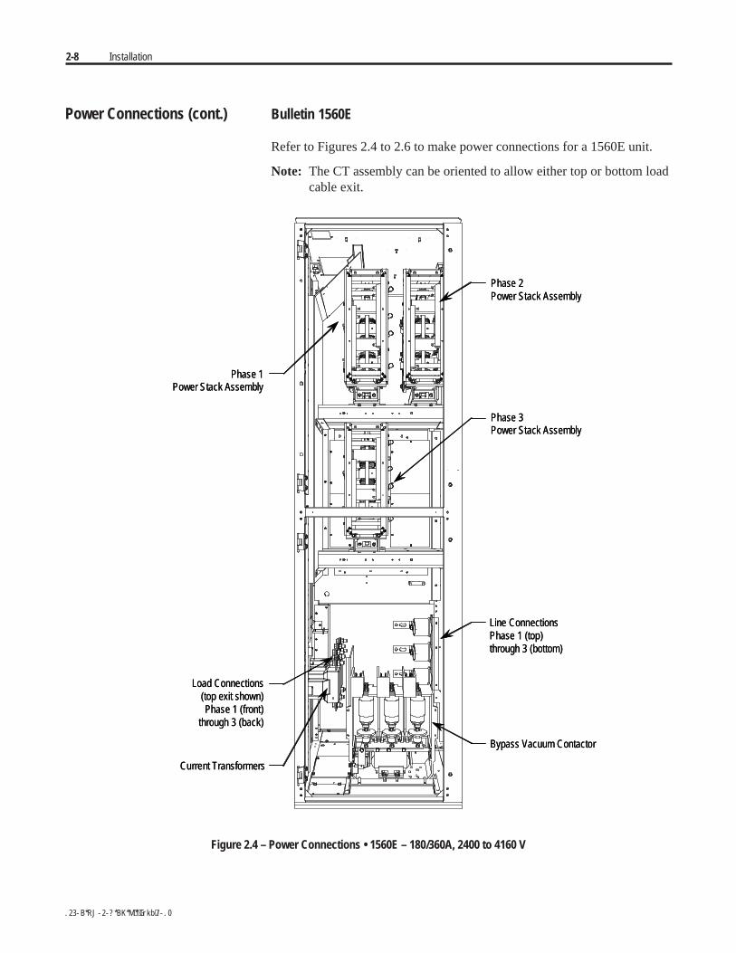
Power Connections (cont.) Bulletin 1560E
Refer to Figures 2.4 to 2.6 to make power connections for a 1560E unit.
Note: The CT assembly can be oriented to allow either top or bottom loadcable exit.
Phase 2Power Stack Assembly
Phase 3Power Stack Assembly
Line ConnectionsPhase 1 (top)through 3 (bottom)
Bypass Vacuum Contactor
Current Transformers
Load Connections(top exit shown)Phase 1 (front)
through 3 (back)
Phase 1Power Stack Assembly
Phase 2Power Stack Assembly
Phase 3Power Stack Assembly
Line ConnectionsPhase 1 (top)through 3 (bottom)
Bypass Vacuum Contactor
Current Transformers
Load Connections(top exit shown)Phase 1 (front)
through 3 (back)
Phase 1Power Stack Assembly
Figure 2.4 – Power Connections • 1560E – 180/360A, 2400 to 4160 V
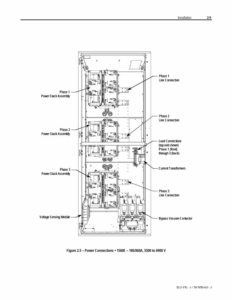
Installation 2-9
Phase 1Line Connection
Phase 2Line Connection
Load Connections(top exit shown)Phase 1 (front)through 3 (back)
Current Transformers
Phase 3Line Connection
Bypass Vacuum Contactor
Phase 1Power Stack Assembly
Phase 2Power Stack Assembly
Phase 3Power Stack Assembly
Voltage Sensing Module
Phase 1Line Connection
Phase 2Line Connection
Load Connections(top exit shown)Phase 1 (front)through 3 (back)
Current Transformers
Phase 3Line Connection
Bypass Vacuum Contactor
Phase 1Power Stack Assembly
Phase 2Power Stack Assembly
Phase 3Power Stack Assembly
Voltage Sensing Module
Figure 2.5 – Power Connections • 1560E – 180/360A, 5500 to 6900 V
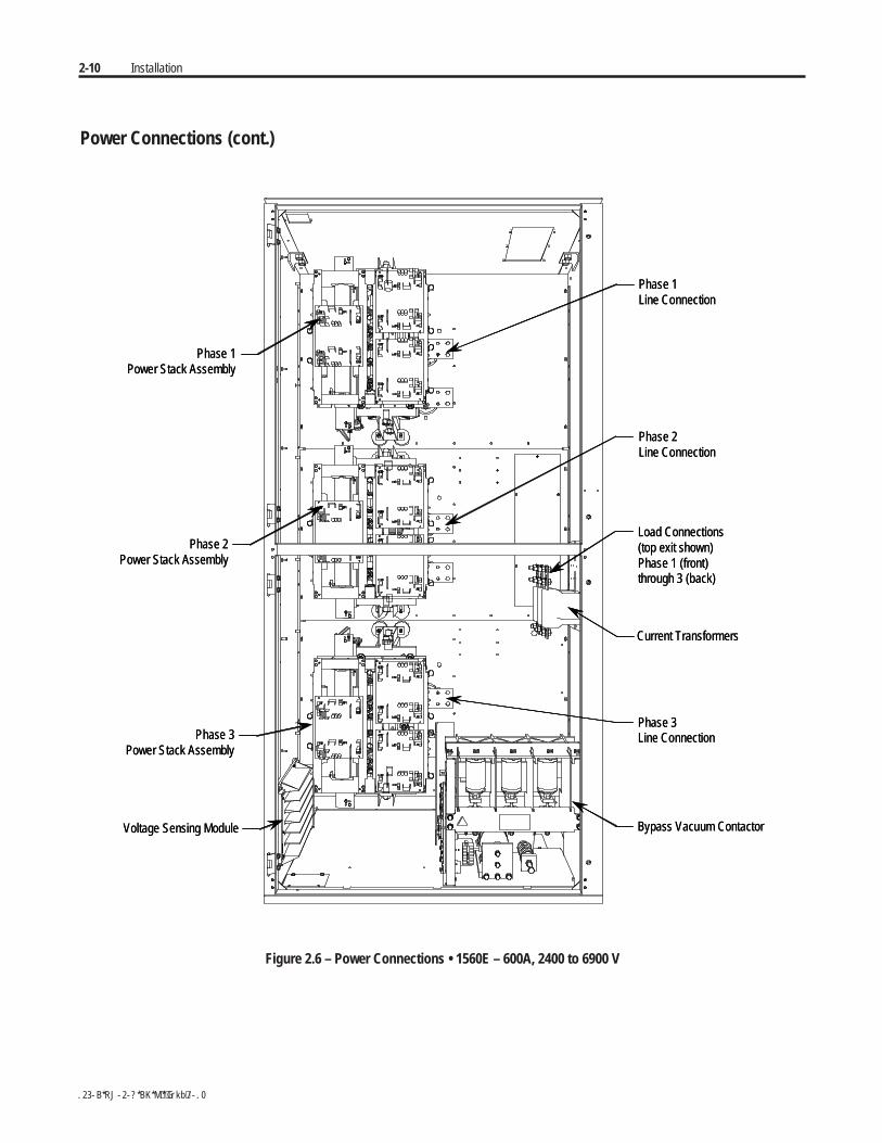
2-10 Installation
Power Connections (cont.)
Phase 1Line Connection
Phase 2Line Connection
Load Connections(top exit shown)Phase 1 (front)through 3 (back)
Current Transformers
Phase 3Line Connection
Bypass Vacuum Contactor
Phase 1Power Stack Assembly
Phase 2Power Stack Assembly
Phase 3Power Stack Assembly
Voltage Sensing Module
Phase 1Line Connection
Phase 2Line Connection
Load Connections(top exit shown)Phase 1 (front)through 3 (back)
Current Transformers
Phase 3Line Connection
Bypass Vacuum Contactor
Phase 1Power Stack Assembly
Phase 2Power Stack Assembly
Phase 3Power Stack Assembly
Voltage Sensing Module
Figure 2.6 – Power Connections • 1560E – 600A, 2400 to 6900 V
Installation 2-11
Important: For retrofit units (Bul. 1560E), the CEC and NEC require thatbranch-circuit protection of the AC line input to the controller be providedby a circuit breaker or motor starter. This function is included with aBulletin 1562E.
Important: The control and signal wires should be positioned at leastsix (6) inches (150 mm) from power cables. Additional noise suppressionpractices (including separate steel conduits for signal leads, etc.) arerecommended.
Bulletin 1503E
For 1503E, refer to applicable documentation from OEM for installation,grounding, interlocking and wiring. This manual should be utilized inconjunction with the OEM supplied documentation, and is suitable forcommissioning, programming, calibration, metering, serial communica-tions, diagnostics, troubleshooting, and maintenance of a standard solid-state controller.

2-12 Installation
Power Wiring The wire sizes must be selected individually, observing all applicablesafety and CEC or NEC regulations. The minimum permissible wire sizedoes not necessarily result in the best operating economy. The minimumrecommended size for the wires between the controller and the motor is thesame as that used if a main voltage source connection to the motor was used.The distance between the controller and motor may affect the size of theconductors used.
Consult the wiring diagrams and appropriate CEC or NEC regulations todetermine correct power wiring. If assistance is needed, contact your areaRockwell Automation Sales Office.
Interlocking Hinged doors and panels, which provide access to medium voltagecomponents, must be mechanically interlocked to ensure circuit isolation.If a combination MV SMC-Flex (1562E) is purchased from RockwellAutomation, all medium voltage compartments will be mechanicallyinterlocked such that they cannot be opened unless the isolating switch forthe unit is open. Each medium voltage door is interlocked to the isolatingswitch handle. To open the doors, move the isolating switch to the OFFposition and loosen the two retaining bolts on the main power cell door.Once this door is open, the other doors may be opened in sequence,depending on the specific interlock scheme provided. The retrofit-typeMV SMC-Flex (1560E) is intended to be added to an existing motorcontroller, and has no isolating means included.
For 1503E and 1560E, it is the responsibility of theinstaller/user to ensure the equipment interlockingscheme is in place and functional before energizing theequipment. Inadequate interlocking could exposepersonnel to energized parts which could result in severeburns, injury or death.
NOTE: Rockwell Automation can assist with the selection of an appro-priate interlocking method, which may include mechanical modificationsto the cabinet(s) or key-type lock systems.
NOTE: An auxiliary cabinet may be attached to the main structure. It willbe ram-interlocked with the main power cell door, which will not allow itto be opened until the main power cell door is opened.
A T T E N T I O NA T T E N T I O N
Installation 2-13
Installation Physical Location
The controller is designed for limited front access (components may have tobe removed) and should be installed with adequate and safe clearance toallow for total door opening. The back of the unit may be placed against awall and several units may be set end to end. In special cases where floorspace is limited and the unit is not against a wall, certain cabinet sectionsmay be placed back to back. This requirement must be stated in the speci-fications in order to mechanically alter the controller.
Fan
The controller may include a cooling fan which is used to cool the component.It should be checked for free operation and no obstruction of the airflow.
Ground Bus Bar
Controllers which are delivered in two (or more) sections, or retrofit controllers,will require that the ground bus bar (6 mm x 51 mm) [¼ in. x 2 inches],which runs the entire length of the equipment in the center back side, bereconnected. A mechanical lug for #8-#10 AWG or #6-250 MCM cable issupplied at the incoming end of the line-up. When the sections are broughttogether, bus links are used to connect the bus bars.
Important: Refer to 2-high, Series B drawings in Publication1500-UM055B-EN-P for power/ground bus connection.
Power and Control Wiring
Controllers consisting of two or more sections will require that the powerand control wiring be connected per the schematic drawings provided.
Control Cables
Control cable entry/exit should be located near the terminal blocks; customer’sconnections are to be routed along the empty side of the terminals. Nyloncable tie loops are provided at the left, front corner of the cabinet to routecontrol cables safely behind the low voltage panel hinges. Cables shouldbe routed so they do not interfere with the swing of the low-voltage panels.
Fibre-Optic Cables
The small, gray, fibre-optic cables are fragile and must be protected duringinstallation from sharp bends and impact.
2-14 Installation
Installation (cont.) Power Factor Correction Capacitors
The controller can be installed on a system with power factor correctioncapacitors. The capacitors must be located on the line side of the controller.This is required to prevent damage to the SCRs in the MV SMC-Flexcontroller. A separate switching contactor is recommended to apply thecapacitors only after the bypass contactor has closed, and to remove themwhen the bypass contactor opens. See Figure 2.7 for two differentacceptable connection methods.
NOTE: Consult the factory if there are any capacitors on the samebranch circuit as the MV SMC-Flex.
When discharged, a capacitor has essentially zero impedance. Forswitching, sufficient impedance should be connected in series with thecapacitor bank to limit the inrush current. A method of limiting the surgecurrent is to add inductance in the capacitor conductors. This can be accom-plished by putting turns or coils of wire in the power connections to thecapacitors (6-inch diameter coil, six loops). For more information, referto NEMA standard ICS 2, Part 2, Capacitor Applications.
Care should be used in mounting the coils so that they are not stackeddirectly on top of each other or they will have a cancelling effect. Also,the coils should be mounted on insulated supports away from metal partsso they will not act like induction heaters.
Any covers or barriers removed during installation mustbe replaced and securely fastened before energizingequipment. Failure to do so may result in severe burns,injury or death.
A T T E N T I O NA T T E N T I O N
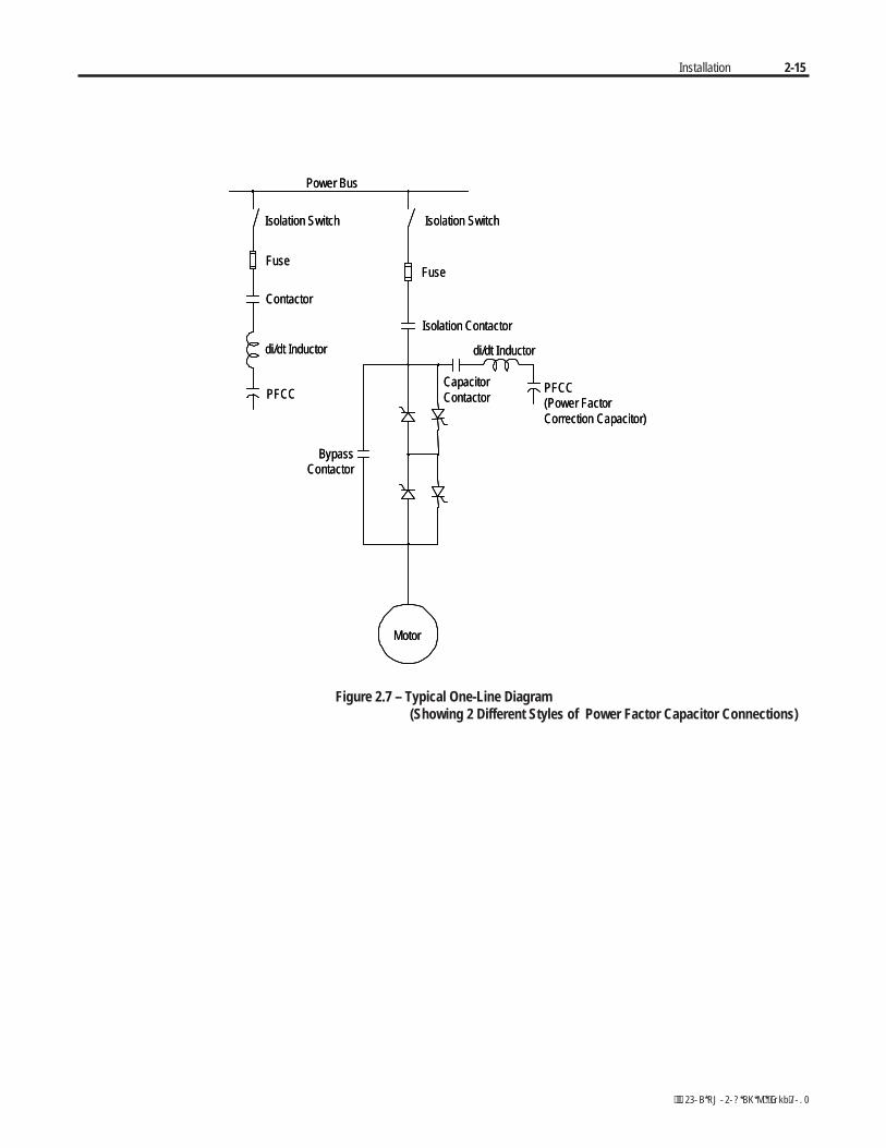
Installation 2-15
Power Bus
Isolation Switch Isolation Switch
FuseFuse
Contactor
Isolation Contactor
PFCC
di/dt Inductor
BypassContactor
Motor
CapacitorContactor
PFCC(Power FactorCorrection Capacitor)
di/dt Inductor
Power Bus
Isolation Switch Isolation Switch
FuseFuse
Contactor
Isolation Contactor
PFCC
di/dt Inductor
BypassContactor
Motor
CapacitorContactor
PFCC(Power FactorCorrection Capacitor)
di/dt Inductor
Figure 2.7 – Typical One-Line Diagram (Showing 2 Different Styles of Power Factor Capacitor Connections)
2-16 Installation
Rockwell Automation highly recommends that motor surge capacitors and/ormotor surge arresters not be located on the load side of the SMC. Theissues that warrant this are:
• Motor and system inductance limits the rate at which the current canchange through the SMC. If capacitance is added at the motor, theinductance is negated. The surge capacitors downstream of the SMCrepresent a near zero impedance when presented with a step voltagefrom the turn on of the SCRs near the line voltage peak. This causes ahigh level of di/dt to occur, due to the fact that the motor cables aregenerally short in length. There is very little impedance between thecapacitor and SCR to limit the di/dt of this capacitor charging current.This can result in damage to the power semiconductors (SCRs) in theSMC.
• It is essential to understand the clamping voltage of the arresters andtype of grounding used in the distribution system. The switching of theSCRs generates slightly higher than nominal peak line to groundvoltages. The typical peaks are 1.5 times the nominal line to groundpeak voltages. These may cause the arresters to conduct, which couldaffect the operation of the SMC and result in faults. Depending uponthe instance at which the arresters conduct, this could also result inSCR damage.
• The capacitance in combination with the line and motor impedancecould also be excited by the voltage steps from SCR switching tocreate resonant voltage swings which could exceed the device voltagewithstanding ratings or surge arrester rating, or cause distorted voltagesignals which may be misinterpreted by the MV SMC-Flex controlsystem.
Surge Arrestor ProtectionDevices
Installation 2-17
Motor Overload Protection Thermal motor overload protection is provided as standard (though it mustbe programmed) with the MV SMC-Flex controller. If the overload tripclass is less than the acceleration time of the motor, nuisance tripping mayoccur.
Overload protection should be properly coordinated withthe motor to avoid damage to equipment.
Two special applications require consideration: Two-speed Motors, andMulti-motor Protection.
Two-speed Motors
The MV SMC-Flex controller has overload protection available for singlespeed motors. When the MV SMC-Flex controller is applied to a two-speedmotor, the Overload Class parameter must be programmed to OFF, andseparate overload relays must be provided for each speed.
Multi-motor Protection
The MV SMC-Flex controller provides overload protection for only onemotor. When the MV SMC-Flex is controlling more than one motor, theOverload Class Parameter must be programmed to OFF, and individualoverload protection is required for each motor.
A T T E N T I O NA T T E N T I O N
2-18 Installation
This product has been designed for Class A equipment.Use of the product in domestic environments may causeradio interference, in which case, the installer may needto employ additional mitigation methods.
The following guidelines are provided for EMC installation compliance.
Enclosure
Install the product in a grounded metal enclosure.
Wiring
Wire in an industrial control application can be divided into three groups:power, control, and signal. The following recommendations for physicalseparation between these groups is provided to reduce the coupling effect.
• Different wire groups should cross at 90° inside an enclosure.
• Minimum spacing between different wire groups in the same tray shouldbe 16 cm (6 in.).
• Wire runs outside an enclosure should be run in conduit or haveshielding/armor with equivalent attenuation.
• Different wire groups should be run in separate conduits.
• Minimum spacing between conduits containing different wire groupsshould be 8 cm (3 in.).
• For additional guidelines, please refer to Wiring and Ground guidelines,publication DRIVES-IN001A-EN-P.
• Wire earth ground to control terminal 14.
• Use shielded wire for: PTC InputTach InputGround Fault Input
• Terminate shielded wires to terminal 14.
• Ground fault CT must be inside or within 3 m of metal enclosure.
A T T E N T I O NA T T E N T I O NEMC Compliance
Installation 2-19
• To meet produce susceptibility requirements, ferrite cores need to beadded to the communication lines. All cores specified below are the splitcore type, so they can be added to existing connections.
– When using an external HIM (or DPI interface), a core should beadded to the HIM cable near the SMC-Flex control module. Therecommended core is Fair-Rite no. 0431167281 or equivalent.
– When using DeviceNet, two cores need to be added to the DeviceNetcable near the SMC-Flex control module. The recommended cores areTDK ZCAT2033 0930H and TDK ZCAT2035 0930 or equivalent.
Control Power Control Voltage
The SMC-Flex controller will accept a control power input of 100 to 240VAC, (-15 / +10%), 1 phase, 50/60 Hz. Refer to the product nameplate toverify the control power input voltage.
Connect control power to the controller at terminals 11 and 12. The controlpower requirement for the control module is 75 VA. Depending on thespecific application, additional control circuit transformer VA capacitymay be required.
Control Wiring
Table 2.C provides the control terminal wire capacity and the tighteningtorque requirements. Each control terminal will accept a maximum of twowires.
Table 2.C – Control Wiring and Tightening Torque
Wire Size Torque
0.75 to 2.5 mm2 (#18 to #14 AWG) 0.6 Nm (5 lb-in.)
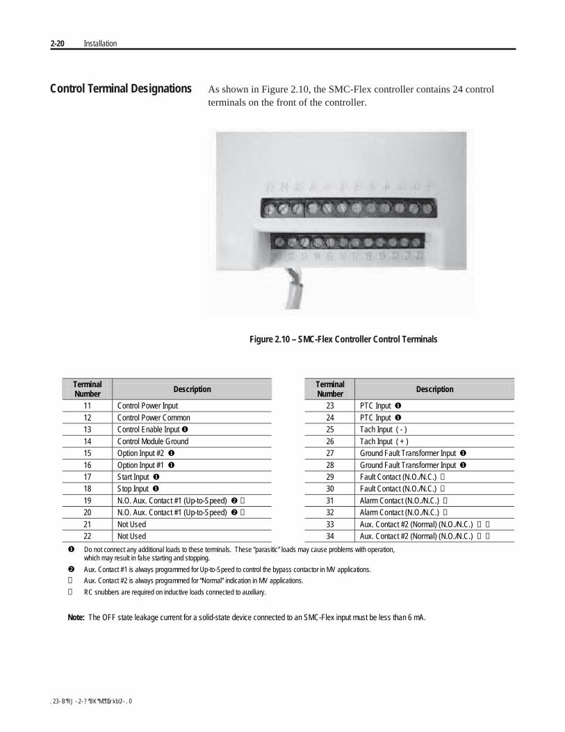
2-20 Installation
Control Terminal Designations As shown in Figure 2.10, the SMC-Flex controller contains 24 controlterminals on the front of the controller.
Figure 2.10 – SMC-Flex Controller Control Terminals
TerminalNumber Description Terminal
Number Description
11 Control Power Input 23 PTC Input
12 Control Power Common 24 PTC Input
13 Control Enable Input 25 Tach Input ( - )14 Control Module Ground 26 Tach Input ( + )15 Option Input #2 27 Ground Fault Transformer Input 16 Option Input #1 28 Ground Fault Transformer Input 17 Start Input 29 Fault Contact (N.O./N.C.) ➍
18 Stop Input 30 Fault Contact (N.O./N.C.) ➍
19 N.O. Aux. Contact #1 (Up-to-Speed) ➍ 31 Alarm Contact (N.O./N.C.) ➍
20 N.O. Aux. Contact #1 (Up-to-Speed) ➍ 32 Alarm Contact (N.O./N.C.) ➍
21 Not Used 33 Aux. Contact #2 (Normal) (N.O./N.C.) ➌ ➍
22 Not Used 34 Aux. Contact #2 (Normal) (N.O./N.C.) ➌ ➍
Do not connect any additional loads to these terminals. These “parasitic” loads may cause problems with operation,which may result in false starting and stopping.
Aux. Contact #1 is always programmed for Up-to-Speed to control the bypass contactor in MV applications.
➌ Aux. Contact #2 is always programmed for “Normal” indication in MV applications.
➍ RC snubbers are required on inductive loads connected to auxiliary.
Note: The OFF state leakage current for a solid-state device connected to an SMC-Flex input must be less than 6 mA.
Commissioning Procedure
Preliminary Set-Up A. Ensure the work area is clean and tidy. Pathways to main disconnectand emergency stop push-button must be clear and unobstructed.
B. The following test equipment is to be prepared for use:
• Test power supply, supplied with each controller
• Multimeters
• Hi-Pot Tester (recommended) or Megger
• Oscilloscope with memory (optional)
C. Complete drawing package and parts list.
D. Specification of project.
Chapter 3
1560E-UM050B-EN-P - June 2013

3-2 Commissioning Procedures1
1560E-UM050B-EN-P - June 2013
System Characteristics
Job Name: _____________________________ Job Number: ________________________________
Rated Voltage: _________________________ Rated Current: _____________ S.F.: ________
Actual Motor Load
Load Type: Fan ___Pump___Conveyor___Compressor___Mixer___
Other_________________________________________
Constant Torque_______ or Variable Torque _______
Actual Motor Data: __________________________________________
Motor HP: _________________________________________________
Motor Rated Speed: _________________________________________
Motor F.L.A.: ______________________________________________
Motor S.F.: ________________________________________________
Motor L.R.A.: ______________________________________________
Frequency: ________________________________________________
Phases: ___________________________________________________
Commissioning Procedures 3-3
1560E-UM050B-EN-P - June 2013
Preliminary Check Ensure that all sources of power are isolated and lockedout before working on installed equipment. Verify thatall circuits are voltage free using a hot stick orappropriate voltage measuring device. Failure to do somay result in severe burns, injury or death.
A. Verify correct power cable phase sequencing, and that connections aretight.
B. Verify power fuse ratings and condition.
C. Verify control fuse ratings and condition.
D. Check that power cable installation has not damaged components, andthat electrical spacings have not been reduced.
E. Check that fibre-optic cables are fully seated in their connectors.
F. Check that circuit board plug connectors are installed and fullyinserted in their sockets.
G. Check that the cooling fan (if supplied) is secured and the rotor is notobstructed.
H. Verify integrity and operation of all interlocks.
I. In the case of the 1503E, verify wiring and perform all tests inconjunction with OEM documentation.
Programming MV SMC-Flex™ Module
Refer to Chapter 4 for programming procedures.
The default (factory) parameter settings are as shown in Appendix B.
Settings may be different on engineered orders, or when option modules orcustomer requirements dictate different settings.
Important: The module should be programmed with an understanding ofhow the SMC functions, and the characteristics of the motor and drivenload. Inappropriate settings may elicit unexpected results such as lack ofacceleration torque or full-voltage starting. For Pump Control applications,refer to Application Considerations on page 1-20.
If the factory settings are not suitable for the application, program themodule to meet the application requirements. Contact your local RockwellAutomation representative or the factory if assistance is required.
A T T E N T I O NA T T E N T I O N
3-4 Commissioning Procedures
1560E-UM050B-EN-P - June 2013
Hi-Pot and Megger Test It is recommended that insulation levels be checked before energizingpower equipment. This may be done with a High Voltage AC insulationtester (HI-POT) or a Megger. See Vacuum Contactor User Manual forsuggested HI-POT testers, and for test procedures for vacuum contactors.If using a Megger, a 5000 volt type is recommended.
Solid-state devices can be destroyed by high voltage.Use jumper wires between heatsinks to short out theSCRs before applying high test voltages to the powercircuit. Disconnect the white wires (1L1, 1T1, 1L2,1T2, 1L3, 1T3) from the voltage feedback board andremove the plug connector. If voltage transformers arepresent, remove one primary fuse from each device. Onthe 1503E, consult OEM documentation for location ofvoltage feedback board
Use caution when performing the HI-POT or MeggerTest. High voltage testing is potentially hazardous andmay cause severe burns, injury or death. Where appro-priate, the case of the test equipment should be connectedto ground.
Insulation may be tested from phase to phase and phase to ground. Therecommended level for AC HI-POT testing is (2 X VLL) Volts, where VLL
is the rated line-to-line voltage of the power system. The leakage currentmay be recorded for future comparison testing, and must be less than 20 mA.
If a Megger is used, it should indicate 50 k megohms or greater if it isisolated as explained in the next paragraph. If the motor is connected, theMegger should indicate 5 k megohms or greater.
If a 1560E is being tested, it is recommended that the input and outputcables be disconnected for each phase. If a 1562E is being tested, it isrecommended that the main contactor be in the open position, and that theoutput cables be disconnected for each phase. (See points marked with anasterisk * in Figure 3.1) This will ensure the unit is isolated from the lineand the motor. The line and the motor may be tested separately to locateproblem areas. If a 1503E is being tested, consult OEM documentation.
After completing the test, remove all semiconductor jumpers and test thedevices with a multimeter to ensure no damage has occurred from theinsulation test. Reconnect the system as it existed prior to this section.Perform the power supply and resistance checks in the following sections.
Failure to reconnect all wires and cables correctly mayresult in equipment damage, personal injury or death.
A T T E N T I O NA T T E N T I O N
A T T E N T I O NA T T E N T I O N
A T T E N T I O NA T T E N T I O N
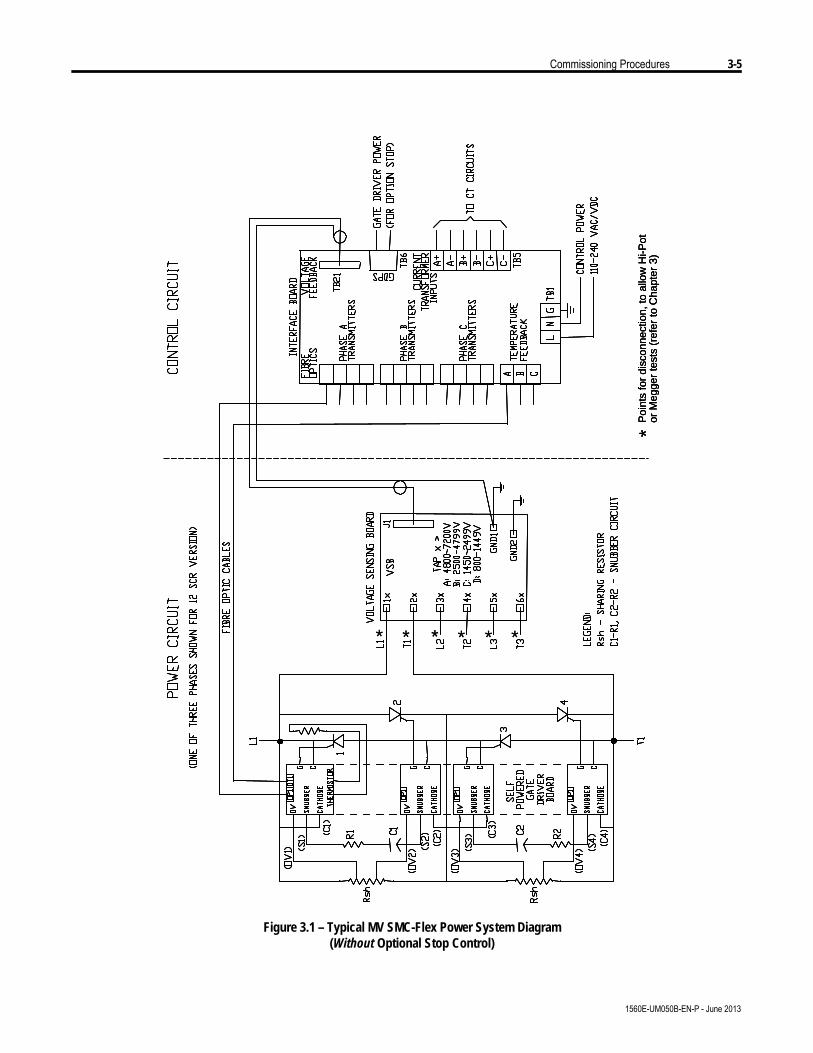
Commissioning Procedures 3-5
1560E-UM050B-EN-P - June 2013
* * *P
oint
s fo
r di
scon
nect
ion,
to a
llow
Hi-P
otor
Meg
ger
test
s (r
efer
to C
hapt
er 3
)
** *** * *
Poi
nts
for
disc
onne
ctio
n, to
allo
w H
i-Pot
or M
egge
rte
sts
(ref
er to
Cha
pter
3)
*
Poi
nts
for
disc
onne
ctio
n, to
allo
w H
i-Pot
or M
egge
rte
sts
(ref
er to
Cha
pter
3)
*
* **
Figure 3.1 – Typical MV SMC-Flex Power System Diagram(Without Optional Stop Control)
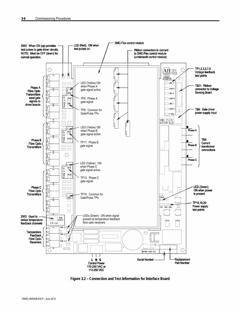
3-6 Commissioning Procedures
1560E-UM050B-EN-P - June 2013
SW2: When ON (up) provides test pulses to gate driver circuits.NOTE: Must be OFF (down) for normal operation.
LED (Red): ON when test pulses on.
SMC-Flex control module
Ribbon connectors to connect to SMC-Flex control module (underneath control module)
TP1,2,3,5,7,9:Voltage feedbacktest points
TB21: Ribbonconnector to Voltage Sensing Board
TB5: Currenttransformerconnections
LED (Green):ON when power is present
TP18,19,20:Power supplytest points
Replacement Part Number
Serial NumberL N GControl Power
110-240 VAC or110-250 VDC
SW3: Used to defeat temperature feedback channels
TemperatureFeedback
Fibre OpticReceivers
Phase CFibre Optic
Transmitters
Phase B Fibre Optic
Transmitters
Phase A Fibre Optic
Transmitterssend gate signals to
driver boards
LED (Yellow) ON when Phase A gate signal active
TP4: Phase A gate signal
TP8: Common for Gate/Pulse TPs
LED (Yellow) ON when Phase B gate signal active
TP11: Phase B gate signal
LED (Yellow): ON when Phase C gate signal active
TP13: Phase C gate signal
TP15: Common for Gate/Pulse TPs
LEDs (Green): ON when signal present at temperature feedback fibre optic receivers
Phase A
Phase B
Phase C
TB6: Gate driver power supply input
Figure 3.2 – Connection and Test Information for Interface Board
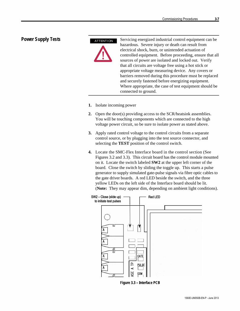
Commissioning Procedures 3-7
1560E-UM050B-EN-P - June 2013
Power Supply Tests Servicing energized industrial control equipment can behazardous. Severe injury or death can result fromelectrical shock, burn, or unintended actuation ofcontrolled equipment. Before proceeding, ensure that allsources of power are isolated and locked out. Verifythat all circuits are voltage free using a hot stick orappropriate voltage measuring device. Any covers orbarriers removed during this procedure must be replacedand securely fastened before energizing equipment.Where appropriate, the case of test equipment should beconnected to ground.
1. Isolate incoming power
2. Open the door(s) providing access to the SCR/heatsink assemblies.You will be touching components which are connected to the highvoltage power circuit, so be sure to isolate power as stated above.
3. Apply rated control voltage to the control circuits from a separatecontrol source, or by plugging into the test source connector, andselecting the TEST position of the control switch.
4. Locate the SMC-Flex Interface board in the control section (SeeFigures 3.2 and 3.3). This circuit board has the control module mountedon it. Locate the switch labeled SW2 at the upper left corner of theboard. Close the switch by sliding the toggle up. This starts a pulsegenerator to supply simulated gate-pulse signals via fibre optic cables tothe gate driver boards. A red LED beside the switch, and the threeyellow LEDs on the left side of the Interface board should be lit.(Note: They may appear dim, depending on ambient light conditions).
SW2 – Close (slide up)to initiate test pulses
Red LEDSW2 – Close (slide up)to initiate test pulses
Red LED
Figure 3.3 – Interface PCB
A T T E N T I O NA T T E N T I O N
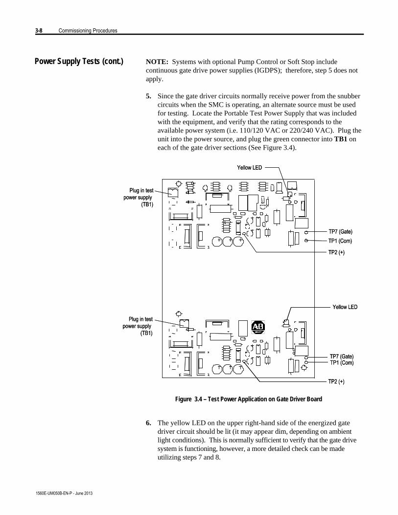
3-8 Commissioning Procedures
1560E-UM050B-EN-P - June 2013
Power Supply Tests (cont.) NOTE: Systems with optional Pump Control or Soft Stop includecontinuous gate drive power supplies (IGDPS); therefore, step 5 does notapply.
5. Since the gate driver circuits normally receive power from the snubbercircuits when the SMC is operating, an alternate source must be usedfor testing. Locate the Portable Test Power Supply that was includedwith the equipment, and verify that the rating corresponds to theavailable power system (i.e. 110/120 VAC or 220/240 VAC). Plug theunit into the power source, and plug the green connector into TB1 oneach of the gate driver sections (See Figure 3.4).
Yellow LED
Plug in testpower supply
(TB1)
Yellow LED
Plug in testpower supply
(TB1)
TP2 (+)
TP1 (Com)TP7 (Gate)
TP7 (Gate)TP1 (Com)
TP2 (+)
Yellow LED
Plug in testpower supply
(TB1)
Yellow LED
Plug in testpower supply
(TB1)
TP2 (+)
TP1 (Com)TP7 (Gate)
TP7 (Gate)TP1 (Com)
TP2 (+)
Figure 3.4 – Test Power Application on Gate Driver Board
6. The yellow LED on the upper right-hand side of the energized gatedriver circuit should be lit (it may appear dim, depending on ambientlight conditions). This is normally sufficient to verify that the gate drivesystem is functioning, however, a more detailed check can be madeutilizing steps 7 and 8.
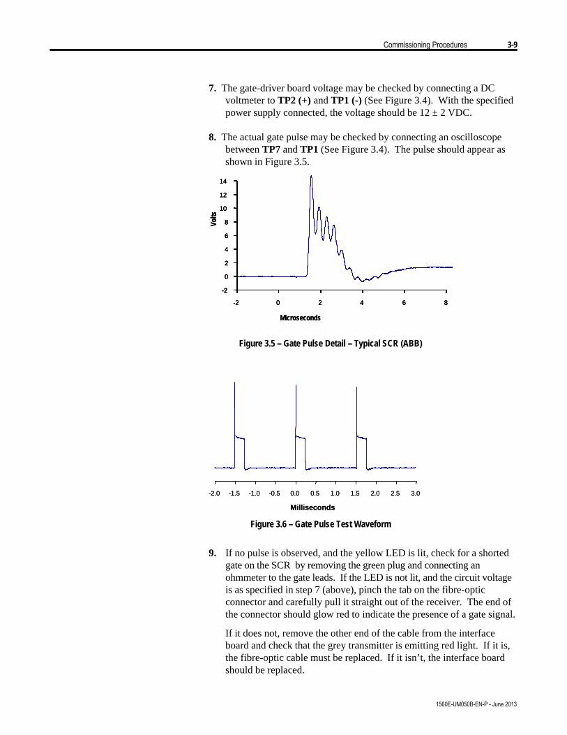
Commissioning Procedures 3-9
1560E-UM050B-EN-P - June 2013
7. The gate-driver board voltage may be checked by connecting a DCvoltmeter to TP2 (+) and TP1 (-) (See Figure 3.4). With the specifiedpower supply connected, the voltage should be 12 ± 2 VDC.
8. The actual gate pulse may be checked by connecting an oscilloscopebetween TP7 and TP1 (See Figure 3.4). The pulse should appear asshown in Figure 3.5.
Microseconds
Volts
-2
0
2
4
6
8
10
12
14
-2 0 2 4 6 8
Microseconds
Volts
-2
0
2
4
6
8
10
12
14
-2 0 2 4 6 8
-2
0
2
4
6
8
10
12
14
-2 0 2 4 6 8
Figure 3.5 – Gate Pulse Detail – Typical SCR (ABB)
-2.0 -1.5 -1.0 -0.5 0.0 0.5 1.0 1.5 2.0 2.5 3.0
Milliseconds
-2.0 -1.5 -1.0 -0.5 0.0 0.5 1.0 1.5 2.0 2.5 3.0
Milliseconds
Figure 3.6 – Gate Pulse Test Waveform
9. If no pulse is observed, and the yellow LED is lit, check for a shortedgate on the SCR by removing the green plug and connecting anohmmeter to the gate leads. If the LED is not lit, and the circuit voltageis as specified in step 7 (above), pinch the tab on the fibre-opticconnector and carefully pull it straight out of the receiver. The end ofthe connector should glow red to indicate the presence of a gate signal.
If it does not, remove the other end of the cable from the interfaceboard and check that the grey transmitter is emitting red light. If it is,the fibre-optic cable must be replaced. If it isn’t, the interface boardshould be replaced.
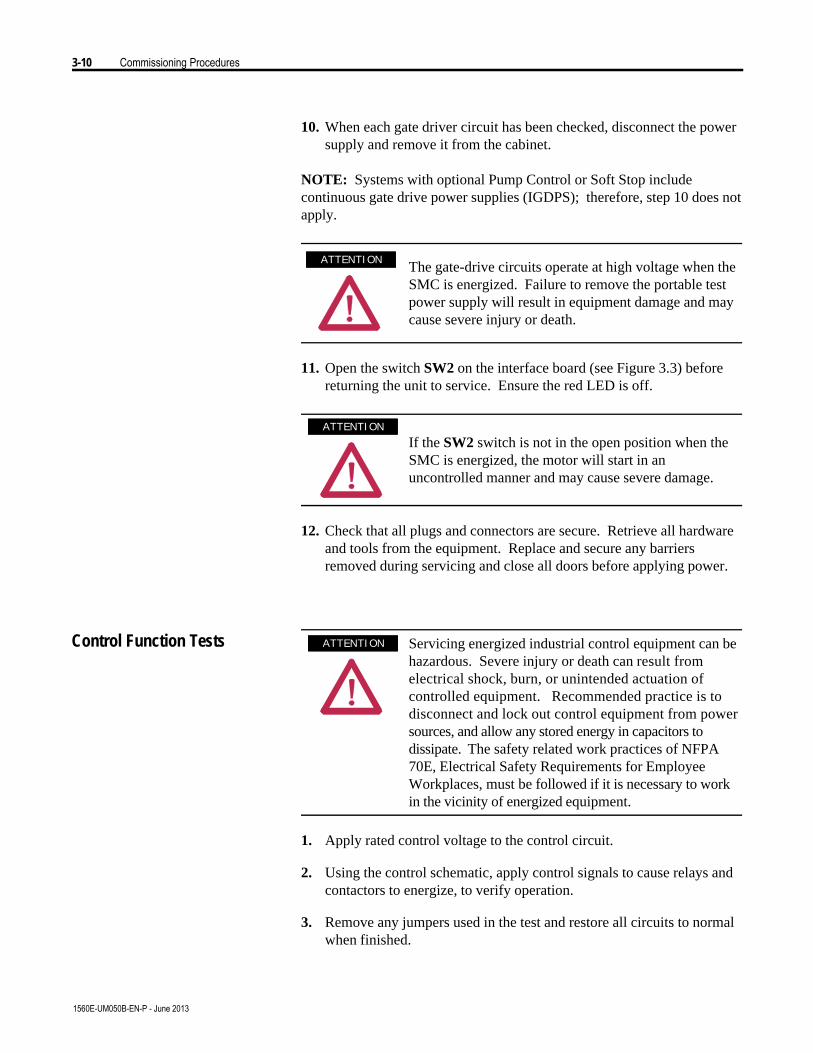
3-10 Commissioning Procedures
1560E-UM050B-EN-P - June 2013
10. When each gate driver circuit has been checked, disconnect the powersupply and remove it from the cabinet.
NOTE: Systems with optional Pump Control or Soft Stop includecontinuous gate drive power supplies (IGDPS); therefore, step 10 does notapply.
The gate-drive circuits operate at high voltage when theSMC is energized. Failure to remove the portable testpower supply will result in equipment damage and maycause severe injury or death.
11. Open the switch SW2 on the interface board (see Figure 3.3) beforereturning the unit to service. Ensure the red LED is off.
If the SW2 switch is not in the open position when theSMC is energized, the motor will start in anuncontrolled manner and may cause severe damage.
12. Check that all plugs and connectors are secure. Retrieve all hardwareand tools from the equipment. Replace and secure any barriersremoved during servicing and close all doors before applying power.
Servicing energized industrial control equipment can behazardous. Severe injury or death can result fromelectrical shock, burn, or unintended actuation ofcontrolled equipment. Recommended practice is todisconnect and lock out control equipment from powersources, and allow any stored energy in capacitors todissipate. The safety related work practices of NFPA70E, Electrical Safety Requirements for EmployeeWorkplaces, must be followed if it is necessary to workin the vicinity of energized equipment.
1. Apply rated control voltage to the control circuit.
2. Using the control schematic, apply control signals to cause relays andcontactors to energize, to verify operation.
3. Remove any jumpers used in the test and restore all circuits to normalwhen finished.
A T T E N T I O NA T T E N T I O N
A T T E N T I O NA T T E N T I O N
A T T E N T I O NA T T E N T I O N
Control Function Tests

Commissioning Procedures 3-11
1560E-UM050B-EN-P - June 2013
Resistance Checks To ensure that resistors and connections have not been damaged duringshipment and installation, the following resistance tests should be performedbefore energizing the starter.
1. Remove all power from the equipment.
Verify that all circuits are voltage free using a hot stickor appropriate voltage measuring device. Severe injuryor death can result from electrical shock, burn, orunintended actuation of controlled equipment.
2. Measure DC resistance per the following chart:
Table 3.A – Power Circuit Resistance Measurements
Location of Probes 1000 V 1300 V 1500 V 2300 V 3300 V 4160 V 5500 V 6900 V
Cathode to Cathode (KOhms) Ê – – – – 22-30 23-31 21-29 24-32
Cathode to Cathode (KOhms) Ë 17-23 19-25 20-27 21-29 40-53 43-57 60-80 w 64-84 Ì
Cathode to Gate (Ohms) 10-40 10-40 10-40 10-40 10-40 10-40 10-40 10-40 Ê Measured between terminals “Cathode” on SPGD Boards, upper two or bottom two within a phase. Ë Measured between terminals “Cathode” on SPGD Boards, top to bottom within a phase. Ì Measured between line and load terminals within a phase.
3. If abnormal readings are obtained, refer to Power Circuit Trouble-shooting on page 9-12.
Voltage Sensing Module The voltage-sensing module consists of a voltage sensing board andmounting plate (refer to Figure 9.2). The voltage sensing board has sixindependent channels which convert voltages up to 10800 V (7.2 kV @1.5 pu) down to low voltage levels which can be used by the SMC-Flexcontrol logic.
Table 3.B shows the input voltage ranges for each of the input terminalson the voltage-sensing module. This module has been designed to operateat a nominal input voltage of up to 7200 V with a continuous 40%overvoltage. The output voltages are scaled to provide close to 10 V peakfor a 140% input voltage at the high end of each of the voltage ranges.
Each of the channels has four taps to provide a range of input voltages, andsoftware will be used to scale the output to show the correct value on theSMC-Flex front panel display. (See Parameter #106 – MV Ratio)
A T T E N T I O NA T T E N T I O N
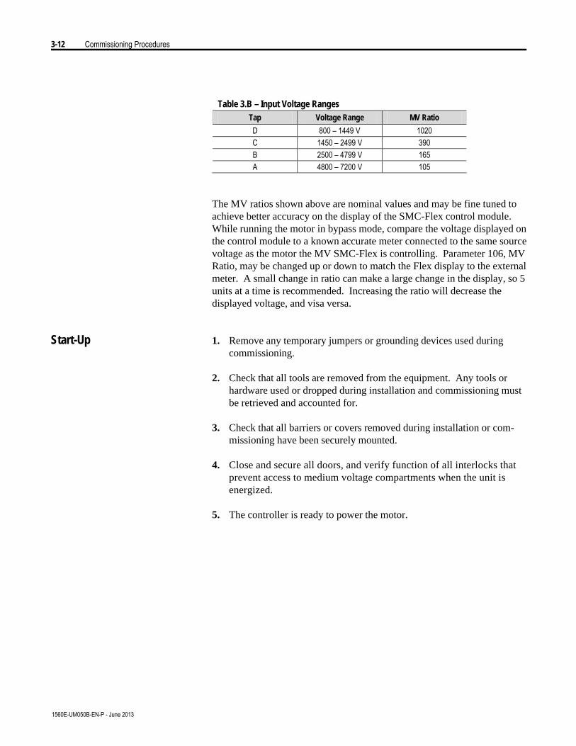
3-12 Commissioning Procedures
1560E-UM050B-EN-P - June 2013
Table 3.B – Input Voltage Ranges Tap Voltage Range MV Ratio
D 800 – 1449 V 1020 C 1450 – 2499 V 390 B 2500 – 4799 V 165 A 4800 – 7200 V 105
The MV ratios shown above are nominal values and may be fine tuned toachieve better accuracy on the display of the SMC-Flex control module.While running the motor in bypass mode, compare the voltage displayed onthe control module to a known accurate meter connected to the same sourcevoltage as the motor the MV SMC-Flex is controlling. Parameter 106, MVRatio, may be changed up or down to match the Flex display to the externalmeter. A small change in ratio can make a large change in the display, so 5units at a time is recommended. Increasing the ratio will decrease thedisplayed voltage, and visa versa.
Start-Up 1. Remove any temporary jumpers or grounding devices used duringcommissioning.
2. Check that all tools are removed from the equipment. Any tools orhardware used or dropped during installation and commissioning mustbe retrieved and accounted for.
3. Check that all barriers or covers removed during installation or com-missioning have been securely mounted.
4. Close and secure all doors, and verify function of all interlocks thatprevent access to medium voltage compartments when the unit isenergized.
5. The controller is ready to power the motor.
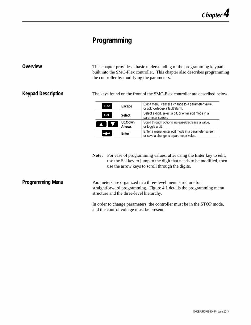
Programming
Overview This chapter provides a basic understanding of the programming keypadbuilt into the SMC-Flex controller. This chapter also describes programmingthe controller by modifying the parameters.
Keypad Description The keys found on the front of the SMC-Flex controller are described below.
Escape Exit a menu, cancel a change to a parameter value, or acknowledge a fault/alarm.
Select Select a digit, select a bit, or enter edit mode in a parameter screen.
Up/Down Arrows
Scroll through options increase/decrease a value, or toggle a bit.
Enter Enter a menu, enter edit mode in a parameter screen, or save a change to a parameter value.
Note: For ease of programming values, after using the Enter key to edit,use the Sel key to jump to the digit that needs to be modified, thenuse the arrow keys to scroll through the digits.
Programming Menu Parameters are organized in a three-level menu structure forstraightforward programming. Figure 4.1 details the programming menustructure and the three-level hierarchy.
In order to change parameters, the controller must be in the STOP mode,and the control voltage must be present.
Chapter 4
1560E-UM050B-EN-P - June 2013
EscEsc
SelSel
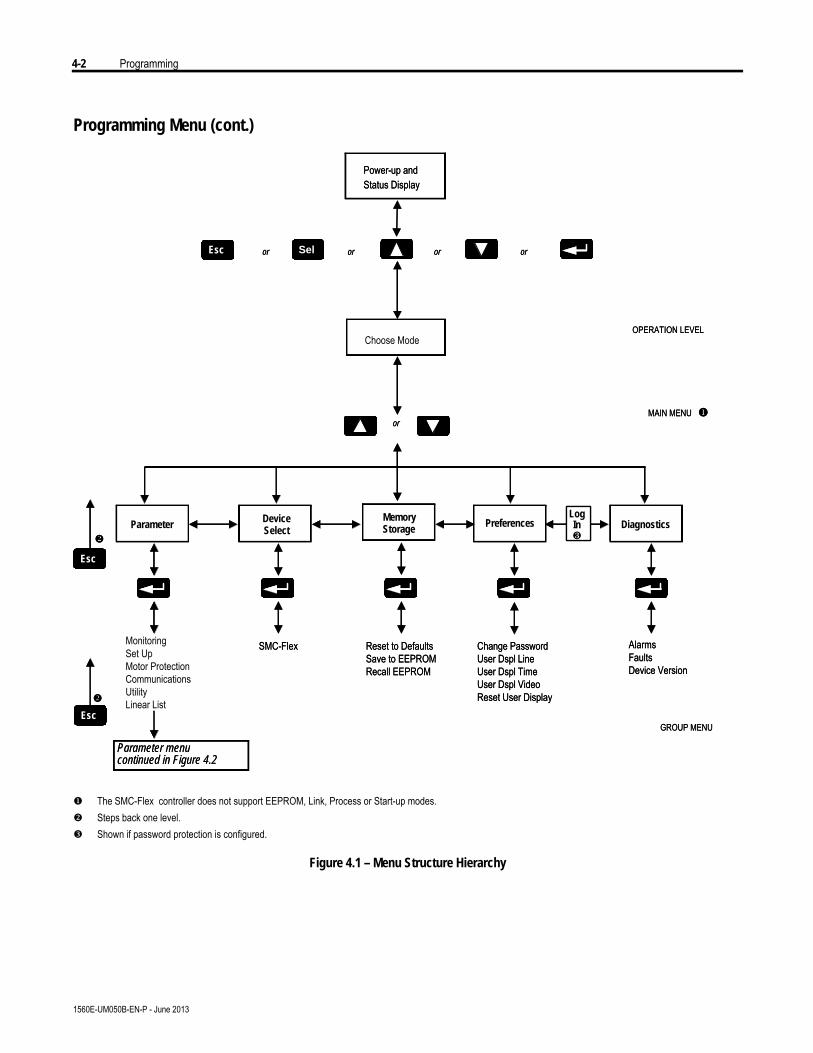
4-2 Programming
1560E-UM050B-EN-P - June 2013
Programming Menu (cont.)
Device
Power-up andStatus Display
ParameterMemoryStorage Preferences DiagnosticsSelect
Choose ModeOPERATION LEVEL
MAIN MENU u
v
Parameter menucontinued in Figure 4.2
GROUP MENU
or oror or
or
Esc
Esc
Esc
v
Sel
Monitoring Set UpMotor ProtectionCommunicationsUtility Linear List
SMC-Flex Reset to DefaultsSave to EEPROMRecall EEPROM
Change PasswordUser Dspl LineUser Dspl TimeUser Dspl VideoReset User Display
AlarmsFaultsDevice Version
LogIn¸
Device
Power-up andStatus Display
ParameterMemoryStorage Preferences DiagnosticsSelect
Choose ModeOPERATION LEVEL
MAIN MENU u
v
Parameter menucontinued in Figure 4.2
GROUP MENU
or oror or
or
EscEsc
EscEsc
EscEsc
v
SelSel
Monitoring Set UpMotor ProtectionCommunicationsUtility Linear List
SMC-Flex Reset to DefaultsSave to EEPROMRecall EEPROM
Change PasswordUser Dspl LineUser Dspl TimeUser Dspl VideoReset User Display
AlarmsFaultsDevice Version
LogIn¸
u The SMC-Flex controller does not support EEPROM, Link, Process or Start-up modes.v Steps back one level.w Shown if password protection is configured.
Figure 4.1 – Menu Structure Hierarchy
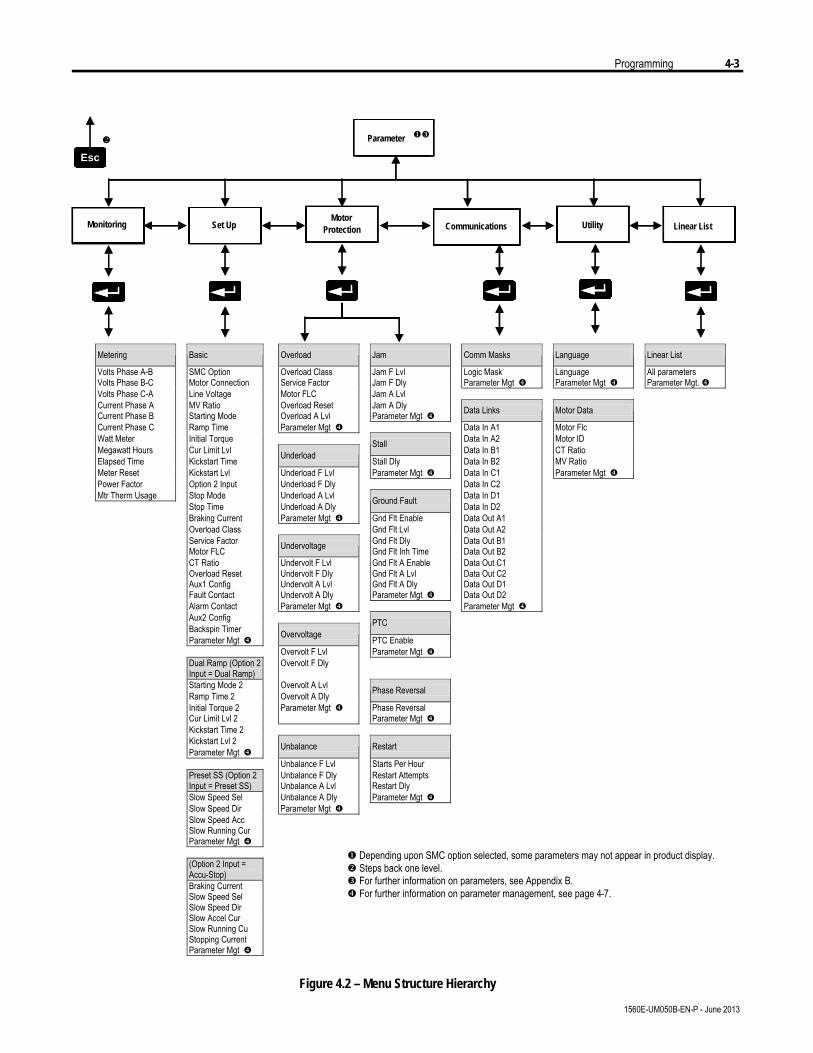
Programming 4-3
1560E-UM050B-EN-P - June 2013
Parameter
MotorSet Up Utility Linear ListProtection
Parameter
Monitoring Communications
uwv
Esc
Parameter
MotorSet Up Utility Linear ListProtection
Parameter
Monitoring Communications
uwv
EscEsc
Metering Basic Overload Jam Comm Masks Language Linear List
Volts Phase A-B SMC Option Overload Class Jam F Lvl Logic Mask Language All parameters Volts Phase B-C Motor Connection Service Factor Jam F Dly Parameter Mgt x Parameter Mgt x Parameter Mgt. x Volts Phase C-A Line Voltage Motor FLC Jam A Lvl Current Phase A MV Ratio Overload Reset Jam A Dly Current Phase B Starting Mode Overload A Lvl Parameter Mgt x Data Links Motor Data Current Phase C Ramp Time Parameter Mgt x Data In A1 Motor Flc Watt Meter Initial Torque Data In A2 Motor ID Megawatt Hours Cur Limit Lvl Stall Data In B1 CT Ratio Elapsed Time Kickstart Time Underload Stall Dly Data In B2 MV Ratio Meter Reset Kickstart Lvl Underload F Lvl Parameter Mgt x Data In C1 Parameter Mgt x Power Factor Option 2 Input Underload F Dly Data In C2 Mtr Therm Usage Stop Mode Underload A Lvl Data In D1 Stop Time Underload A Dly Ground Fault Data In D2 Braking Current Parameter Mgt x Gnd Flt Enable Data Out A1 Overload Class Gnd Flt Lvl Data Out A2 Service Factor Gnd Flt Dly Data Out B1 Motor FLC Undervoltage Gnd Flt Inh Time Data Out B2 CT Ratio Undervolt F Lvl Gnd Flt A Enable Data Out C1 Overload Reset Undervolt F Dly Gnd Flt A Lvl Data Out C2 Aux1 Config Undervolt A Lvl Gnd Flt A Dly Data Out D1 Fault Contact Undervolt A Dly Parameter Mgt x Data Out D2 Alarm Contact Parameter Mgt x Parameter Mgt x Aux2 Config
Backspin Timer PTC Parameter Mgt x
Overvoltage PTC Enable
Overvolt F Lvl Parameter Mgt x Dual Ramp (Option 2 Input = Dual Ramp)
Overvolt F Dly
Starting Mode 2 Overvolt A Lvl Ramp Time 2 Overvolt A Dly Phase Reversal Initial Torque 2 Parameter Mgt x Phase Reversal Cur Limit Lvl 2 Parameter Mgt x Kickstart Time 2 Kickstart Lvl 2 Parameter Mgt x Unbalance Restart Unbalance F Lvl Starts Per Hour Preset SS (Option 2 Unbalance F Dly Restart Attempts Input = Preset SS) Unbalance A Lvl Restart Dly Slow Speed Sel Unbalance A Dly Parameter Mgt x Slow Speed Dir Parameter Mgt x Slow Speed Acc Slow Running Cur Parameter Mgt x (Option 2 Input =
Accu-Stop)
Braking Current Slow Speed Sel Slow Speed Dir Slow Accel Cur Slow Running Cu Stopping Current
Parameter Mgt x
Figure 4.2 – Menu Structure Hierarchy
u Depending upon SMC option selected, some parameters may not appear in product display.v Steps back one level.w For further information on parameters, see Appendix B.x For further information on parameter management, see page 4-7.
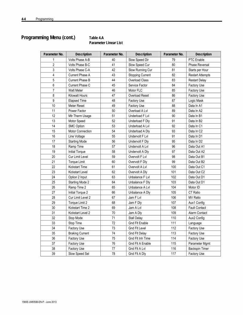
4-4 Programming
1560E-UM050B-EN-P - June 2013
Programming Menu (cont.) Table 4.AParameter Linear List
Parameter No. Description Parameter No. Description Parameter No. Description
1 Volts Phase A-B 40 Slow Speed Dir 79 PTC Enable 2 Volts Phase B-C 41 Slow Speed Cur 80 Phase Reversal 3 Volts Phase C-A 42 Slow Running Cur 81 Starts per Hour 4 Current Phase A 43 Stopping Current 82 Restart Attempts 5 Current Phase B 44 Overload Class 83 Restart Delay 6 Current Phase C 45 Service Factor 84 Factory Use 7 Watt Meter 46 Motor FLC 85 Factory Use 8 Kilowatt Hours 47 Overload Reset 86 Factory Use 9 Elapsed Time 48 Factory Use 87 Logic Mask 10 Meter Reset 49 Factory Use 88 Data In A1 11 Power Factor 50 Overload A Lvl 89 Data In A2 12 Mtr Therm Usage 51 Underload F Lvl 90 Data In B1 13 Motor Speed 52 Underload F Dly 91 Data In B2 14 SMC Option 53 Underload A Lvl 92 Data In C1 15 Motor Connection 54 Underload A Dly 93 Data In C2 16 Line Voltage 55 Undervolt F Lvl 91 Data In D1 17 Starting Mode 56 Undervolt F Dly 95 Data In D2 18 Ramp Time 57 Undervolt A Lvl 96 Data Out A1 19 Initial Torque 58 Undervolt A Dly 97 Data Out A2 20 Cur Limit Level 59 Overvolt F Lvl 98 Data Out B1 21 Torque Limit 60 Overvolt F Dly 99 Data Out B2 22 Kickstart Time 61 Overvolt A Lvl 100 Data Out C1 23 Kickstart Level 62 Overvolt A Dly 101 Data Out C2 24 Option 2 Input 63 Unbalance F Lvl 102 Data Out D1 25 Starting Mode 2 64 Unbalance F Dly 103 Data Out D1 26 Ramp Time 2 65 Unbalance A Lvl 104 Motor ID 27 Initial Torque 2 66 Unbalance A Dly 105 CT Ratio 28 Cur Limit Level 2 67 Jam F Lvl 106 MV Ratio 29 Torque Limit 2 68 Jam F Dly 107 Aux1 Config 30 Kickstart Time 2 69 Jam A Lvl 108 Fault Contact 31 Kickstart Level 2 70 Jam A Dly 109 Alarm Contact 32 Stop Mode 71 Stall Delay 110 Aux2 Config 33 Stop Time 72 Gnd Flt Enable 111 Language 34 Factory Use 73 Gnd Flt Level 112 Factory Use 35 Braking Current 74 Gnd Flt Delay 113 Factory Use 36 Factory Use 75 Gnd Flt Inh Time 114 Factory Use 37 Factory Use 76 Gnd Flt A Enable 115 Parameter Mgmt 38 Factory Use 77 Gnd Flt A Lvl 116 Backspin Timer 39 Slow Speed Sel 78 Gnd Flt A Dly 117 Factory Use
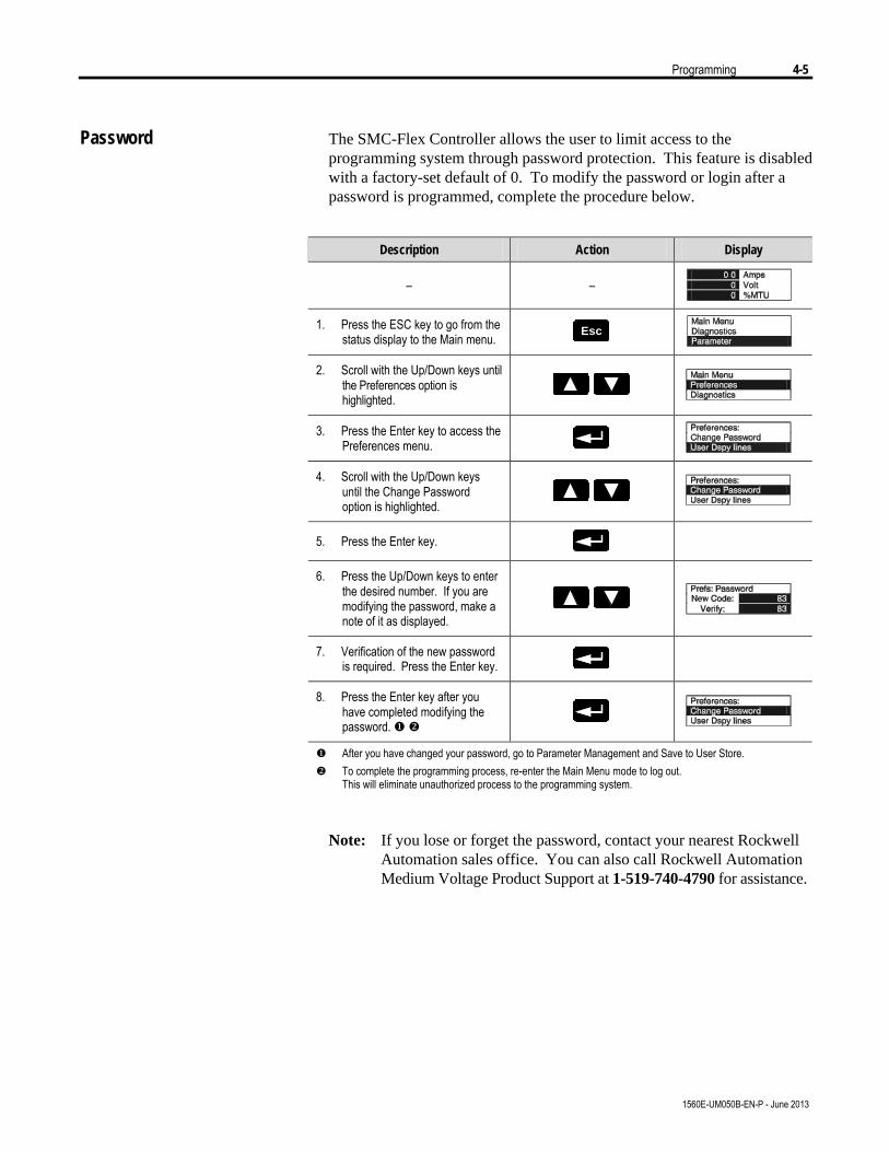
Programming 4-5
1560E-UM050B-EN-P - June 2013
Password The SMC-Flex Controller allows the user to limit access to theprogramming system through password protection. This feature is disabledwith a factory-set default of 0. To modify the password or login after apassword is programmed, complete the procedure below.
Description Action Display
– –
1. Press the ESC key to go from the status display to the Main menu. EscEsc
2. Scroll with the Up/Down keys until the Preferences option is highlighted.
3. Press the Enter key to access the Preferences menu.
4. Scroll with the Up/Down keys until the Change Password option is highlighted.
5. Press the Enter key.
6. Press the Up/Down keys to enter the desired number. If you are modifying the password, make a note of it as displayed.
7. Verification of the new password is required. Press the Enter key.
8. Press the Enter key after you have completed modifying the password. u v
u After you have changed your password, go to Parameter Management and Save to User Store. v To complete the programming process, re-enter the Main Menu mode to log out.
This will eliminate unauthorized process to the programming system.
Note: If you lose or forget the password, contact your nearest RockwellAutomation sales office. You can also call Rockwell AutomationMedium Voltage Product Support at 1-519-740-4790 for assistance.
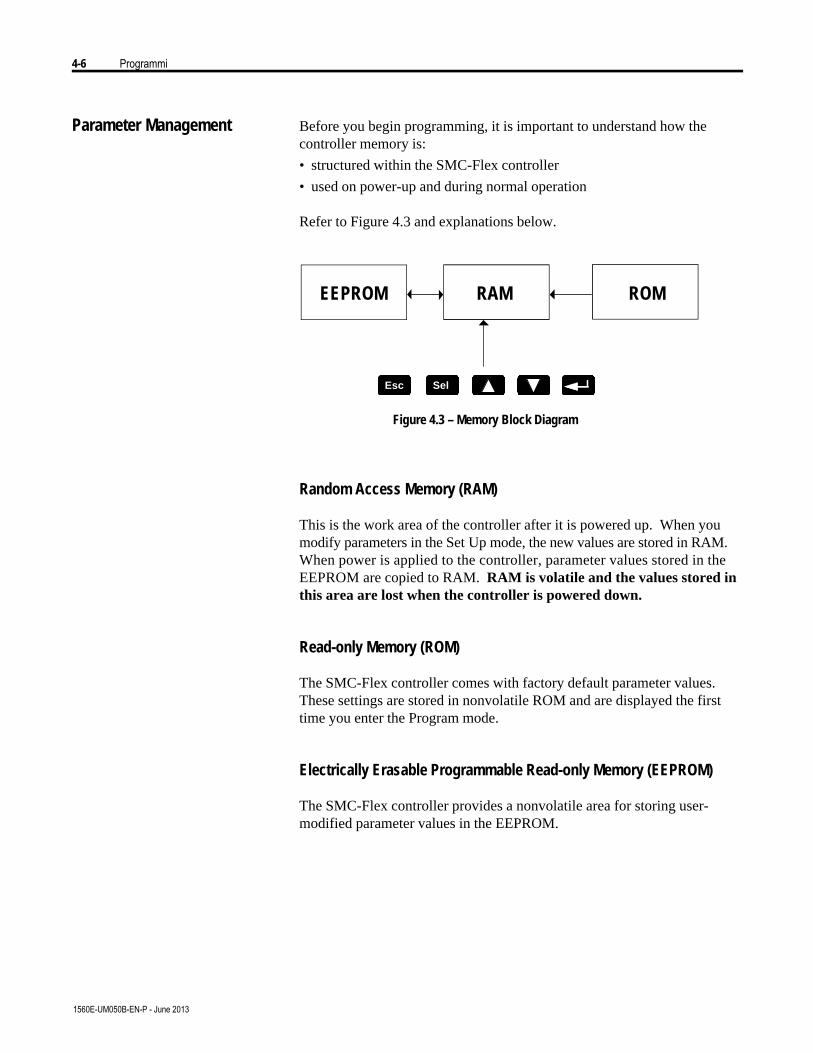
4-6 Programmi
1560E-UM050B-EN-P - June 2013
Parameter Management Before you begin programming, it is important to understand how thecontroller memory is:• structured within the SMC-Flex controller• used on power-up and during normal operation
Refer to Figure 4.3 and explanations below.
EEPROM RAM ROM
Figure 4.3 – Memory Block Diagram
Random Access Memory (RAM)
This is the work area of the controller after it is powered up. When youmodify parameters in the Set Up mode, the new values are stored in RAM.When power is applied to the controller, parameter values stored in theEEPROM are copied to RAM. RAM is volatile and the values stored inthis area are lost when the controller is powered down.
Read-only Memory (ROM)
The SMC-Flex controller comes with factory default parameter values.These settings are stored in nonvolatile ROM and are displayed the firsttime you enter the Program mode.
Electrically Erasable Programmable Read-only Memory (EEPROM)
The SMC-Flex controller provides a nonvolatile area for storing user-modified parameter values in the EEPROM.
EscEsc SelSel
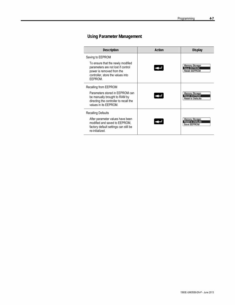
Programming 4-7
1560E-UM050B-EN-P - June 2013
Using Parameter Management
Description Action Display
Saving to EEPROM To ensure that the newly modified
parameters are not lost if control power is removed from the controller, store the values into EEPROM.
Recalling from EEPROM Parameters stored in EEPROM can
be manually brought to RAM by directing the controller to recall the values in its EEPROM.
Recalling Defaults After parameter values have been
modified and saved to EEPROM, factory default settings can still be re-initialized.
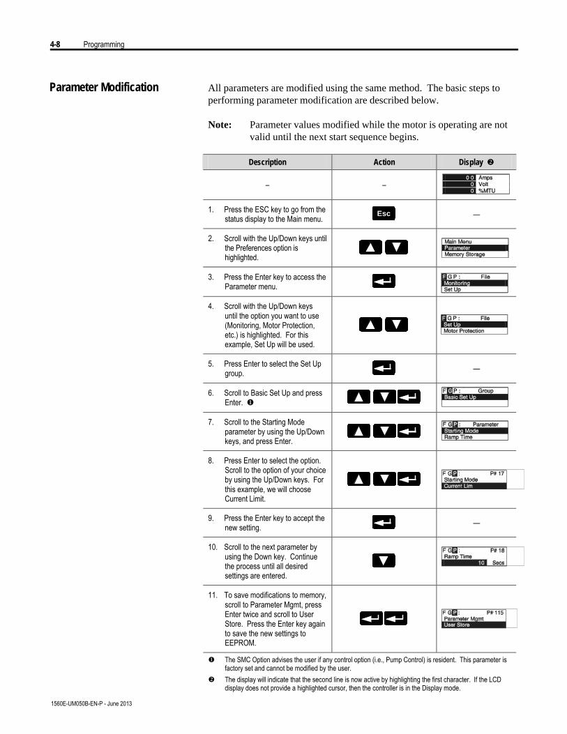
4-8 Programming
1560E-UM050B-EN-P - June 2013
Parameter Modification All parameters are modified using the same method. The basic steps toperforming parameter modification are described below.
Note: Parameter values modified while the motor is operating are notvalid until the next start sequence begins.
Description Action Display v
– –
1. Press the ESC key to go from the status display to the Main menu. EscEsc —
2. Scroll with the Up/Down keys until the Preferences option is highlighted.
3. Press the Enter key to access the Parameter menu.
4. Scroll with the Up/Down keys until the option you want to use (Monitoring, Motor Protection, etc.) is highlighted. For this example, Set Up will be used.
5. Press Enter to select the Set Up group. —
6. Scroll to Basic Set Up and press Enter. u
7. Scroll to the Starting Mode parameter by using the Up/Down keys, and press Enter.
8. Press Enter to select the option. Scroll to the option of your choice by using the Up/Down keys. For this example, we will choose Current Limit.
9. Press the Enter key to accept the new setting. —
10. Scroll to the next parameter by using the Down key. Continue the process until all desired settings are entered.
11. To save modifications to memory, scroll to Parameter Mgmt, press Enter twice and scroll to User Store. Press the Enter key again to save the new settings to EEPROM.
u The SMC Option advises the user if any control option (i.e., Pump Control) is resident. This parameter is factory set and cannot be modified by the user.
v The display will indicate that the second line is now active by highlighting the first character. If the LCD display does not provide a highlighted cursor, then the controller is in the Display mode.
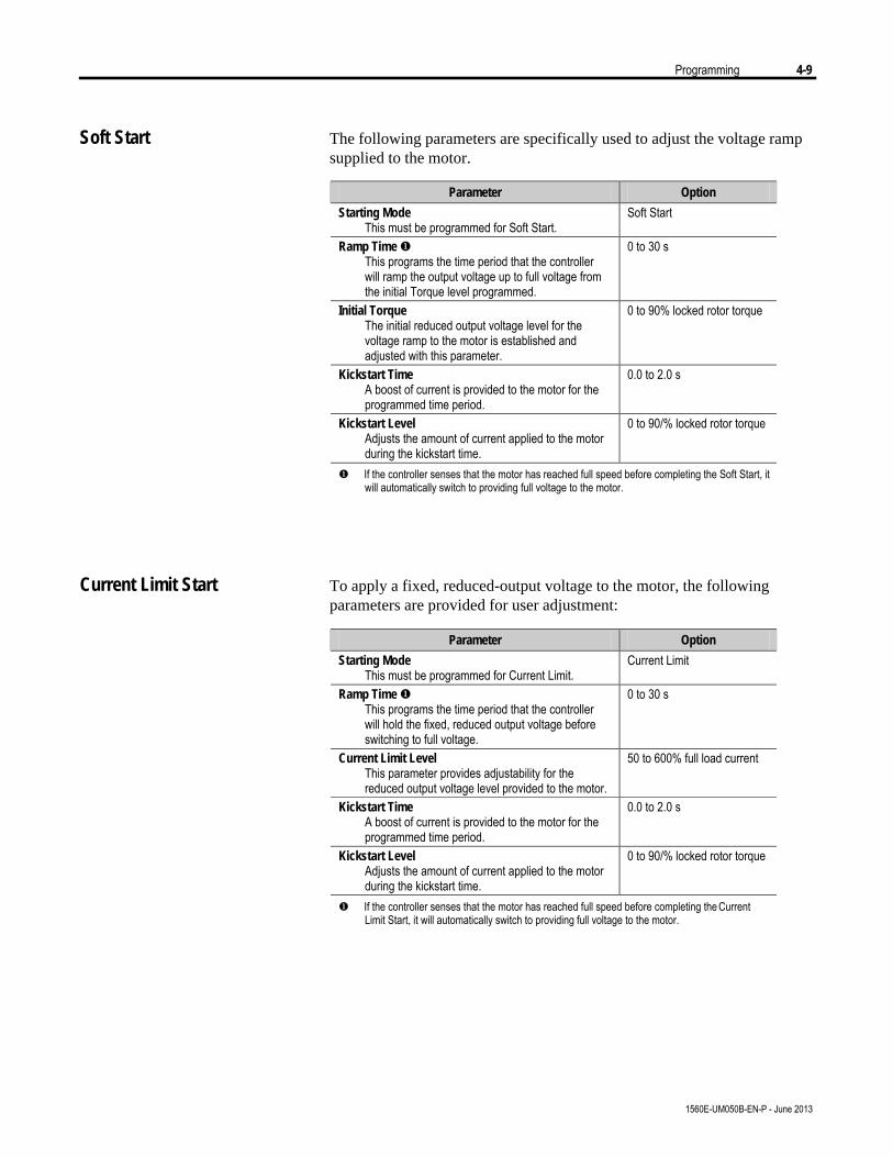
Programming 4-9
1560E-UM050B-EN-P - June 2013
Soft Start The following parameters are specifically used to adjust the voltage rampsupplied to the motor.
Parameter Option
Starting Mode This must be programmed for Soft Start.
Soft Start
Ramp Time u This programs the time period that the controller will ramp the output voltage up to full voltage from the initial Torque level programmed.
0 to 30 s
Initial Torque The initial reduced output voltage level for the voltage ramp to the motor is established and adjusted with this parameter.
0 to 90% locked rotor torque
Kickstart Time A boost of current is provided to the motor for the programmed time period.
0.0 to 2.0 s
Kickstart Level Adjusts the amount of current applied to the motor during the kickstart time.
0 to 90/% locked rotor torque
u If the controller senses that the motor has reached full speed before completing the Soft Start, it will automatically switch to providing full voltage to the motor.
Current Limit Start To apply a fixed, reduced-output voltage to the motor, the followingparameters are provided for user adjustment:
Parameter Option
Starting Mode This must be programmed for Current Limit.
Current Limit
Ramp Time u This programs the time period that the controller will hold the fixed, reduced output voltage before switching to full voltage.
0 to 30 s
Current Limit Level This parameter provides adjustability for the reduced output voltage level provided to the motor.
50 to 600% full load current
Kickstart Time A boost of current is provided to the motor for the programmed time period.
0.0 to 2.0 s
Kickstart Level Adjusts the amount of current applied to the motor during the kickstart time.
0 to 90/% locked rotor torque
u If the controller senses that the motor has reached full speed before completing the Current Limit Start, it will automatically switch to providing full voltage to the motor.
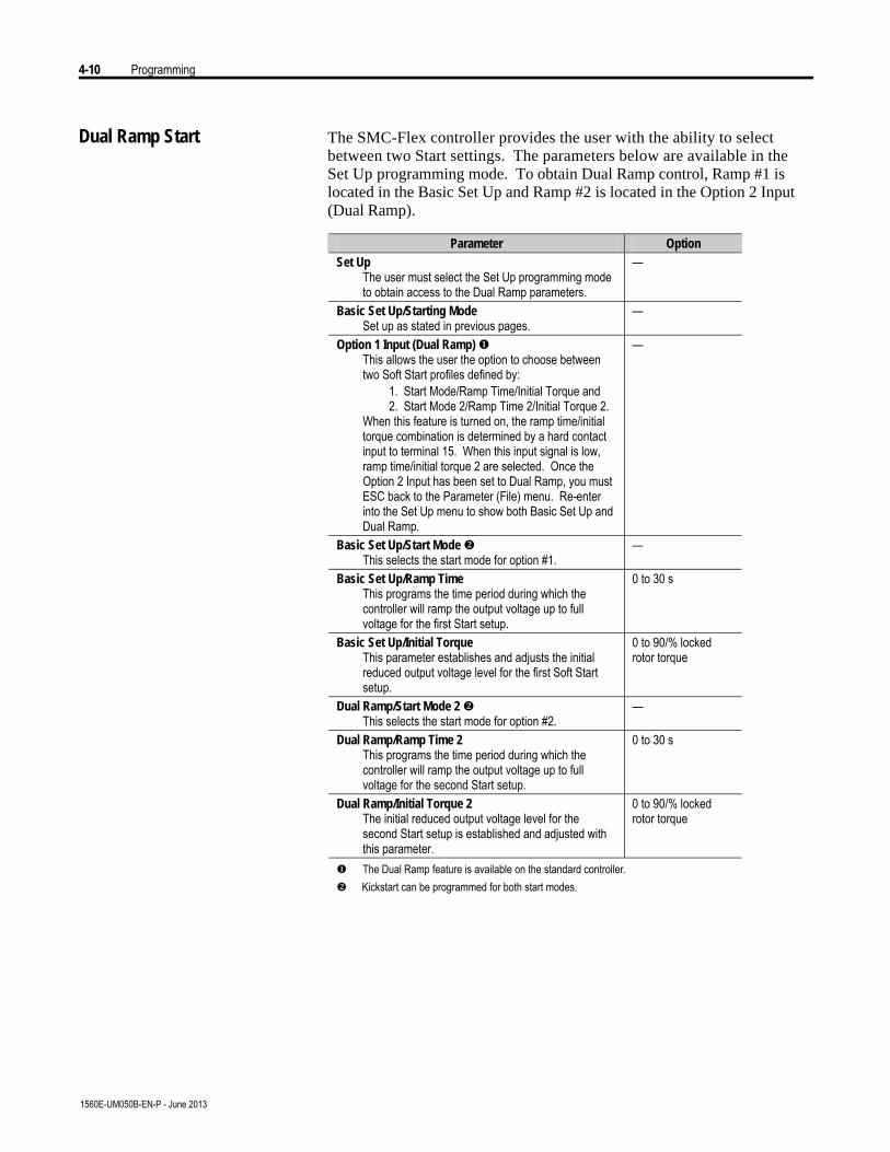
4-10 Programming
1560E-UM050B-EN-P - June 2013
Dual Ramp Start The SMC-Flex controller provides the user with the ability to selectbetween two Start settings. The parameters below are available in theSet Up programming mode. To obtain Dual Ramp control, Ramp #1 islocated in the Basic Set Up and Ramp #2 is located in the Option 2 Input(Dual Ramp).
Parameter Option Set Up
The user must select the Set Up programming mode to obtain access to the Dual Ramp parameters.
—
Basic Set Up/Starting Mode Set up as stated in previous pages.
—
Option 1 Input (Dual Ramp) u This allows the user the option to choose between two Soft Start profiles defined by: 1. Start Mode/Ramp Time/Initial Torque and 2. Start Mode 2/Ramp Time 2/Initial Torque 2. When this feature is turned on, the ramp time/initial torque combination is determined by a hard contact input to terminal 15. When this input signal is low, ramp time/initial torque 2 are selected. Once the Option 2 Input has been set to Dual Ramp, you must ESC back to the Parameter (File) menu. Re-enter into the Set Up menu to show both Basic Set Up and Dual Ramp.
—
Basic Set Up/Start Mode v This selects the start mode for option #1.
—
Basic Set Up/Ramp Time This programs the time period during which the controller will ramp the output voltage up to full voltage for the first Start setup.
0 to 30 s
Basic Set Up/Initial Torque This parameter establishes and adjusts the initial reduced output voltage level for the first Soft Start setup.
0 to 90/% locked rotor torque
Dual Ramp/Start Mode 2 v This selects the start mode for option #2.
—
Dual Ramp/Ramp Time 2 This programs the time period during which the controller will ramp the output voltage up to full voltage for the second Start setup.
0 to 30 s
Dual Ramp/Initial Torque 2 The initial reduced output voltage level for the second Start setup is established and adjusted with this parameter.
0 to 90/% locked rotor torque
u The Dual Ramp feature is available on the standard controller. v Kickstart can be programmed for both start modes.
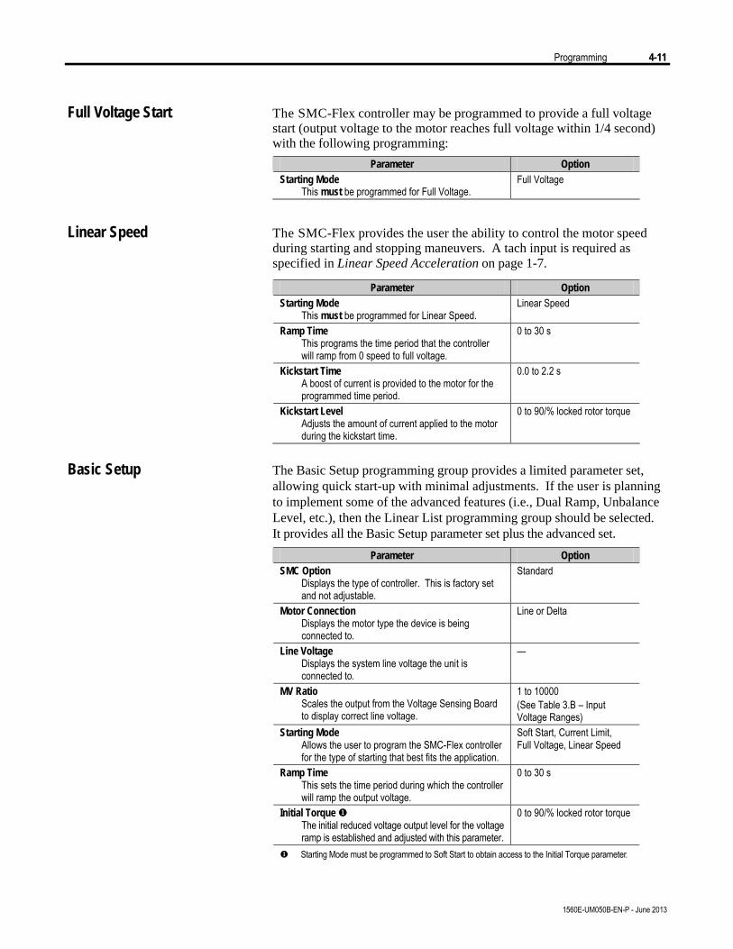
Programming 4-11
1560E-UM050B-EN-P - June 2013
Full Voltage Start The SMC-Flex controller may be programmed to provide a full voltagestart (output voltage to the motor reaches full voltage within 1/4 second)with the following programming:
Parameter Option Starting Mode
This must be programmed for Full Voltage. Full Voltage
Linear Speed The SMC-Flex provides the user the ability to control the motor speedduring starting and stopping maneuvers. A tach input is required asspecified in Linear Speed Acceleration on page 1-7.
Parameter Option Starting Mode
This must be programmed for Linear Speed. Linear Speed
Ramp Time This programs the time period that the controller will ramp from 0 speed to full voltage.
0 to 30 s
Kickstart Time A boost of current is provided to the motor for the programmed time period.
0.0 to 2.2 s
Kickstart Level Adjusts the amount of current applied to the motor during the kickstart time.
0 to 90/% locked rotor torque
Basic Setup The Basic Setup programming group provides a limited parameter set,
allowing quick start-up with minimal adjustments. If the user is planningto implement some of the advanced features (i.e., Dual Ramp, UnbalanceLevel, etc.), then the Linear List programming group should be selected.It provides all the Basic Setup parameter set plus the advanced set.
Parameter Option SMC Option
Displays the type of controller. This is factory set and not adjustable.
Standard
Motor Connection Displays the motor type the device is being connected to.
Line or Delta
Line Voltage Displays the system line voltage the unit is connected to.
—
MV Ratio Scales the output from the Voltage Sensing Board to display correct line voltage.
1 to 10000 (See Table 3.B – Input Voltage Ranges)
Starting Mode Allows the user to program the SMC-Flex controller for the type of starting that best fits the application.
Soft Start, Current Limit, Full Voltage, Linear Speed
Ramp Time This sets the time period during which the controller will ramp the output voltage.
0 to 30 s
Initial Torque u The initial reduced voltage output level for the voltage ramp is established and adjusted with this parameter.
0 to 90/% locked rotor torque
u Starting Mode must be programmed to Soft Start to obtain access to the Initial Torque parameter.

4-12 Programming
1560E-UM050B-EN-P - June 2013
Parameter Option Current Limit Level v
The current limit level that is applied for the Ramp time selected.
50 to 600% FLC
Kickstart Time A boost current is provided to the motor for the programmed time period.
0.0 to 2.0 s
Kickstart Level Adjusts the amount of current applied to the motor during kickstart.
0 to 90% of locked rotor torque
Option 2 Input Allows the user to select a Dual Ramp or Preset Slow Speed (SS).
Disable, Preset SS, Dual Ramp Emergency Run x
Stop Mode Allows the user to program the SMC-Flex controller for the type of stopping that best fits the application.
Disable, Soft Stop, Linear Speed
Stop Time This sets the time period which the controller will ramp the voltage during a stopping maneuver.
0.0 to 120 s
CT Ratio Scales the CT input to actual motor current (5 amp secondary assumed)
1 to 1500
Aux1 Config N.O. contact is provided as standard with the SMC-Flex controller. This contact is located at terminals 19 and 20. Aux Contacts 1 allows the user to configure the operation of the contacts.
Normal, Up-to-speed/Bypass
Fault Contact A fault auxiliary contact is provided between terminals 29 and 30. Fault Contact allows the user to program the operation of the contact for a fault condition.
N.O., N.C.
Alarm Contact An alarm contact is provided between terminals 31 and 32. Alarm contact allows the user to program the operation of the contact for an Alarm condition.
N.O., N.C.
Aux2 Config This parameter provides the user with the ability to program the “Normal” state of the second auxiliary contact. This contact is located at terminals 33 and 34.
N.O., N.C.
Parameter Mgmt w The newly programmed parameters’ values can be saved to memory, or the factory default parameter values can be recalled.
Ready, User Store, User Recall, Load Default
v Starting Mode must be programmed to Current Limit to obtain access to the Current Limit Level parameter.
w The new programmed parameter values will not be stored to the EEPROM without the user’s direction in Parameter Management: User Store.
x When programmed for ‘Emergency Run’ and the Option 2 input is energized, a ‘Start’ command will first close the bypass contactor, then the line contactor for an across-the-line start of the motor. A ‘Stop’ command will open the line contactor first and allow the motor to coast, regardless of the programmed ‘Stop Mode’. For Pump Option modules, the Option 2 input defaults to ‘Emergency Run’ for MV applications.
Basic Setup (cont.)

Programming 4-13
1560E-UM050B-EN-P - June 2013
Motor Protection While the Basic Set Up group allows the user to get started with aminimum number of parameters to modify, the Motor Protection groupallows full access to the SMC-Flex controller's powerful parameter set.Following is a listing of the additional setup parameters provided.
Note: The majority of parameters have a Fault and an Alarm setting.
Parameter Option Overload
Allows the user to select the operation of the overload.
Trip Class, Service Factor, Motor FLC, Overload Reset, Overload Alarm Level
Underload v Determines the trip level as a percentage of the motor’s FLA, and the delay period.
Underload Fault Level, Underload Fault Delay, Underload Alarm Level, Underload Alarm Delay
Undervoltage u Determines the trip level as a percentage of line voltage and delay period.
Undervoltage Fault Level, Undervoltage Fault Delay, Undervoltage Alarm Level, Undervoltage Alarm Delay
Overvoltage u Determines the trip level as a percentage of line voltage and delay period.
Overvoltage Fault Level, Overvoltage Fault Delay, Overvoltage Alarm Level, Overvoltage Alarm Delay
Unbalance u Allows the user to set the current unbalance trip level and delay period.
Unbalance Fault Level, Unbalance Fault Delay, Unbalance Alarm Level, Unbalance Alarm Delay
Jam v Determines the trip level as a percentage of motor full load current and delay period.
Jam Fault Level, Jam Fault Delay, Jam Alarm Level, Jam Alarm Delay
Stall Allows the user to set the stall delay time.
Stall Delay
Ground Fault w Allows the user to enable the ground fault level in amps, delay time and inhibit time. A separate 825-CBCT is required.
Ground Fault Enable, Ground Fault Level, Ground Fault Delay, Ground Fault Inhibit Time, Ground Fault Alarm Enable, Ground Fault Alarm Level, Ground Fault Alarm Delay
PTC x Allows the user to connect a PTC to the SMC and enable a fault when it becomes active.
PTC Enable
Phase Reversal Determines the proper orientation of line connections to the SMC. If Enabled and phases are out of sequence, a fault will be indicated.
Phase Reversal
Restarts Allows the user to determine the maximum number of restarts per hour the unit can experience, and delay time between consecutive starts.
Restarts Per Hour, Restart Attempts, Restart Delay
u The delay time must be set to a value greater than zero when Undervoltage, Overvoltage and Unbalance are enabled.
v For Jam and Underload detection to function, the Motor FLC must be programmed in the Motor Protection group. See Chapter 5 for instructions.
w See details in Ground Fault on page 1-12. x See details in Termistor/PTC Protection on page 1-13.
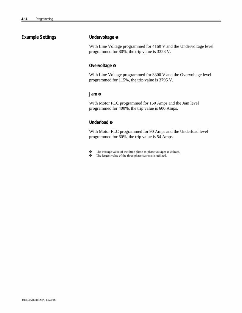
4-14 Programming
1560E-UM050B-EN-P - June 2013
Example Settings Undervoltage u
With Line Voltage programmed for 4160 V and the Undervoltage levelprogrammed for 80%, the trip value is 3328 V.
Overvoltage u
With Line Voltage programmed for 3300 V and the Overvoltage levelprogrammed for 115%, the trip value is 3795 V.
Jam v
With Motor FLC programmed for 150 Amps and the Jam levelprogrammed for 400%, the trip value is 600 Amps.
Underload v
With Motor FLC programmed for 90 Amps and the Underload levelprogrammed for 60%, the trip value is 54 Amps.
u The average value of the three phase-to-phase voltages is utilized.v The largest value of the three phase currents is utilized.

Programming 4-15
1560E-UM050B-EN-P - June 2013
Motor Information The Basic Set Up and Overload programming group allows the user to setparameters indicating to the controller which motor is connected. It isimportant to correctly input the data to achieve the best performance fromyour controller.
For overload protection, it is critical that the data beentered as it appears on the motor nameplate.
Motor Data Entry
In the Program mode, enter the correct values into the Overload group:
Description Option Display
Overload Class vw The factor default setting disables
overload protection. To enable it, enter the desired trip class in this parameter.
Disable, 10, 15, 20, 30
Service Factor vw Enter the value from the motor’s
nameplate.
0.01 to 1.99
Motor FLC uvw Enter the value from the motor’s
nameplate.
1.0 to 1000A
Overload Reset vw Allows the user to select either a manual
or auto reset after an overload.
Manual, Auto
Motor Connection w Enter the type of motor being connected
to the SMC-Flex: Line or Delta
Line, Delta
Line Voltage uw Enter the system voltage in this
parameter. This must be done to ensure optimum motor performance and correct operation of undervoltage and overvoltage protection.
1 to 10,000 V
u Refer to the SMC -Flex controller nameplate for maximum ratings. Exceeding these could result in damage to the controller.
v Found in Overload programming group. Only one location needs to be programmed. w Found in Basic Set Up programming group.
A T T E N T I O NA T T E N T I O N

4-16 Programming
1560E-UM050B-EN-P - June 2013

Metering
Overview While the SMC-Flex controller operates your motor, it also monitorsseveral different parameters, providing a full function metering package.
Viewing Metering Data To access the metering information, follow the procedure below:
Description Action Display
– –
1. Press any key to access the Main menu.
EscEsc
2. Scroll with the Up/Down keys until the Parameter option is shown.
3. Press the Enter key to access the Parameter option. —
4. Scroll with the Up/Down keys until the Monitoring option is displayed.
5. Press the Enter key to access the Monitoring group. —
6. Press the Enter key to access the Metering group.
u Refer to Metering on page 1-16 or Figure 4.2 on page 4-3 for details on the metering functions .
Chapter 5
1560E-UM050B-EN-P - June 2013
u
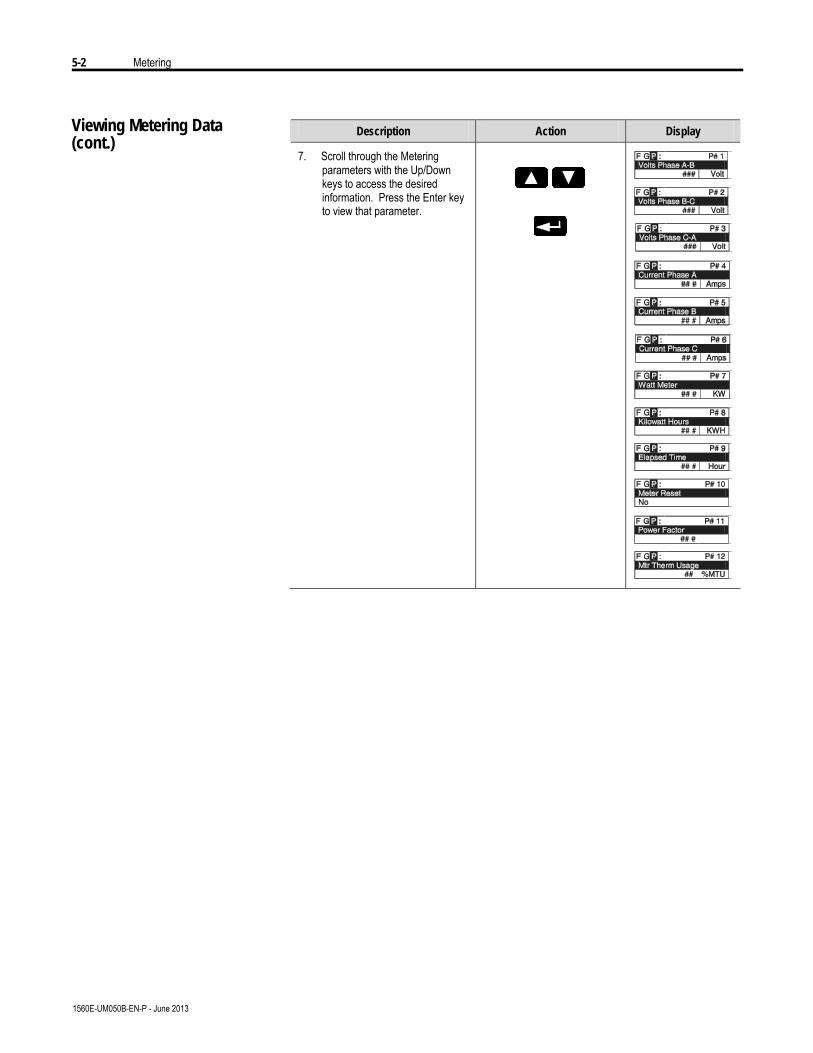
5-2 Metering
1560E-UM050B-EN-P - June 2013
Viewing Metering Data(cont.)
Description Action Display
7. Scroll through the Metering parameters with the Up/Down keys to access the desired information. Press the Enter key to view that parameter.
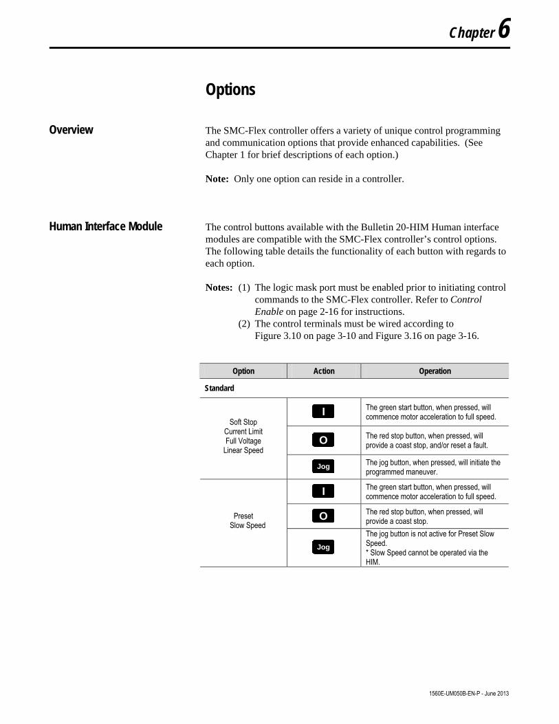
Options
Overview The SMC-Flex controller offers a variety of unique control programmingand communication options that provide enhanced capabilities. (SeeChapter 1 for brief descriptions of each option.)
Note: Only one option can reside in a controller.
Human Interface Module The control buttons available with the Bulletin 20-HIM Human interfacemodules are compatible with the SMC-Flex controller’s control options.The following table details the functionality of each button with regards toeach option.
Notes: (1) The logic mask port must be enabled prior to initiating controlcommands to the SMC-Flex controller. Refer to ControlEnable on page 2-16 for instructions.
(2) The control terminals must be wired according toFigure 3.10 on page 3-10 and Figure 3.16 on page 3-16.
Option Action Operation
Standard
II The green start button, when pressed, will commence motor acceleration to full speed.
OO The red stop button, when pressed, will provide a coast stop, and/or reset a fault.
Soft Stop Current Limit Full Voltage
Linear Speed
JogJog The jog button, when pressed, will initiate the programmed maneuver.
II The green start button, when pressed, will commence motor acceleration to full speed.
OO The red stop button, when pressed, will provide a coast stop. Preset
Slow Speed
JogJog
The jog button is not active for Preset Slow Speed. * Slow Speed cannot be operated via the HIM.
Chapter 6
1560E-UM050B-EN-P - June 2013
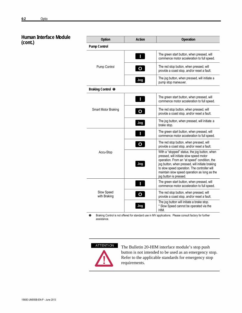
6-2 Optio
1560E-UM050B-EN-P - June 2013
Human Interface Module(cont.)
Option Action Operation
Pump Control
II The green start button, when pressed, will commence motor acceleration to full speed.
OO The red stop button, when pressed, will provide a coast stop, and/or reset a fault.
Pump Control
JogJog The jog button, when pressed, will initiate a pump stop maneuver.
Braking Control Ê
II The green start button, when pressed, will commence motor acceleration to full speed.
OO The red stop button, when pressed, will provide a coast stop, and/or reset a fault.
Smart Motor Braking
JogJog The jog button, when pressed, will initiate a brake stop.
II The green start button, when pressed, will commence motor acceleration to full speed.
OO The red stop button, when pressed, will provide a coast stop, and/or reset a fault.
Accu-Stop
JogJog
With a “stopped” status, the jog button, when pressed, will initiate slow speed motor operation. From an “at speed” condition, the jog button, when pressed, will initiate braking to slow speed operation. The controller will maintain slow speed operation as long as the jog button is pressed.
II The green start button, when pressed, will commence motor acceleration to full speed.
OO The red stop button, when pressed, will provide a coast stop, and/or reset a fault.
Slow Speed with Braking
JogJog The jog button will initiate a brake stop. * Slow Speed cannot be operated via the HIM.
Ê Braking Control is not offered for standard use in MV applications. Please consult factory for further assistance.
The Bulletin 20-HIM interface module’s stop pushbutton is not intended to be used as an emergency stop.Refer to the applicable standards for emergency stoprequirements.
A T T E N T I O NA T T E N T I O N

Options 6-3
1560E-UM050B-EN-P - June 2013
Programming Parameters The following table provides the option-specific parameters that areprovided with each control option. These parameters are in addition tothose already discussed in the Basic Set Up and Metering groups.Diagrams supporting the options described below are shown later in thischapter.
Option Parameter Range
Standard
SMC Option This parameter identifies the type of control present and is not user programmable.
Standard
Soft Stop
Soft Stop Time Allows the user to set the time period for the soft stopping function.
0…120 s
SMC Option This parameter identifies the type of control present and is not user programmable.
Standard
Slow Speed Select Allows the user to program the slow speed that best fits the application.
Low: 7% – Forward, 10% – Reverse High: 15% – Forward, 20% – Reverse
Slow Speed Direction This parameter programs the slow speed motor rotational direction.
Forward, Reverse
Slow Accel Current Allows the user to program the required current to accelerate the motor to slow speed operation.
0…450% of full load current
Preset Slow Speed
Slow Running Current Allows the user to program the required current to operate the motor at the slow speed setting.
0-450% of full load current
Pump Control
SMC Option This parameter identifies the type of control present and is not user programmable.
Pump Control
Pump Stop Time Allows the user to set the time period for the pump stopping function.
0…120 s Pump Control
Starting Mode Allows the user to program the SMC-Flex controller for the type of starting that best fits the application.
Pump Start, Soft Start, Current Limit Start, Full Voltage

6-4 Options
1560E-UM050B-EN-P - June 2013
Option Parameter Range
Braking Control Ë
SMC Option This parameter identifies the type of control present and is not user programmable.
Braking Control
SMB Smart Motor Braking Braking Current u
Allows the user to program the intensity of the braking current applied to the motor.
0…400% of full load current
SMC Option This parameter identifies the type of control present and is not user programmable.
Braking Control
Slow Speed Select Allows the user to program the slow speed that best fits the application.
Low: 7% High: 15%
Slow Accel Current Allows the user to program the required current to accelerate the motor to slow speed operation.
0…450% of full load current
Slow Running Current Allows the user to program the required current to operate the motor at slow speed operation.
0…400% of full load current
Braking Current u Allows the user to program the intensity of the braking current applied to the motor.
0…400% of full load current
Accu-Stop
Stopping Current u Allows the user to program the intensity of the braking current applied to the motor from slow speed operation.
0…400% of full load current
SMC Option This parameter identifies the type of control present and is not user programmable.
Braking Control
Slow Speed Select Allows the user to program the slow speed that best fits the application.
Low: 7% High: 15%
Slow Accel Current Allows the user to program the required current to accelerate the motor to slow speed operation.
0…450% of full load current
Slow Running Current Allows the user to program the required current to operate the motor at the slow speed setting.
0…450% of full load current
Slow Speed with Braking
Braking Current u Allows the user to program the intensity of the braking current applied to the motor.
0…400% of full load current
u All braking/stopping current settings in the range of 1…100% will provide 100% braking current to the motor. Ë Braking Control is not offered for standard use in MV applications. Please consult factory for further assistance.
Programming Parameters(cont.)

Options 6-5
1560E-UM050B-EN-P - June 2013
Control Wiring Refer to Chapter 1 – Product Overview for typical control wiring examplesused with various control schemes.

6-6 Options
1560E-UM050B-EN-P - June 2013
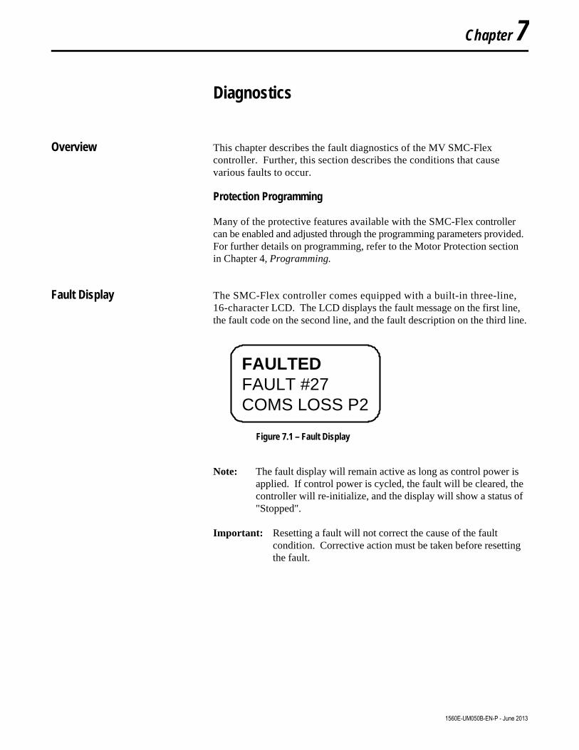
Chapter 7
Diagnostics
Overview This chapter describes the fault diagnostics of the MV SMC-Flexcontroller. Further, this section describes the conditions that causevarious faults to occur.
Protection Programming
Many of the protective features available with the SMC-Flex controllercan be enabled and adjusted through the programming parameters provided.For further details on programming, refer to the Motor Protection sectionin Chapter 4, Programming.
Fault Display The SMC-Flex controller comes equipped with a built-in three-line,16-character LCD. The LCD displays the fault message on the first line,the fault code on the second line, and the fault description on the third line.
FAULTEDFAULT #27COMS LOSS P2
Figure 7.1 – Fault Display
Note: The fault display will remain active as long as control power isapplied. If control power is cycled, the fault will be cleared, thecontroller will re-initialize, and the display will show a status of"Stopped".
Important: Resetting a fault will not correct the cause of the faultcondition. Corrective action must be taken before resettingthe fault.
1560E-UM050B-EN-P - June 2013

7-2 Diagnostics
1560E-UM050B-EN-P - June 2013
Clear Fault You can clear a fault using any of several methods:
• Program the SMC-Flex controller for a Clear Fault, which can befound in Main Menu/Diagnostics/Faults.
• If a human interface module is connected to the controller, press theStop button.
Note: The stop signal will not clear a fault if Logic Mask is disabled(Logic Mask, parameter #87, equals ø).
• Cycle control power to the SMC-Flex controller.
Important: An overload fault cannot be reset until the Motor ThermalUsage, parameter 12, value is below 75%. See Protectionand Diagnostics on page 1-9 for further details.
Fault Buffer The SMC-Flex controller stores in memory the five most recent faults.Display the fault buffer by selecting the View Faults Queue and scrollingthrough the fault buffer parameters. The information is stored as faultcodes and fault descriptions. A fault code cross-reference is provided inTable 7.A.

Diagnostics 7-3
1560E-UM050B-EN-P - June 2013
Fault Codes
Table 7.A provides a complete cross-reference of the available fault codesand corresponding fault descriptions.
Table 7.A Fault Code Cross-Reference
Fault Code Fault Code
Line Loss A 1 Underload 23 Line Loss B 2 Jam 24 Line Loss C 3 Stall 25
Shorted SCR A 4 Phase Reversal 26 Shorted SCR B 5 Coms Loss P2 27 Shorted SCR C 6 Coms Loss P3 28 Open Gate A 7 Coms Loss P5 29 Open Gate B 8 Network P2 30 Open Gate C 9 Network P3 31 PTC Pwr Pole 10 Network P5 32
SCR Overtemp Ê 11 Ground Fault 33 Motor PTC 12 Excess Starts/Hour 34
Open Bypass A 13 Power Loss A 35 Open Bypass B 14 Power Loss B 36 Open Bypass C 15 Power Loss C 37
No Load A 16 Hall ID 38 No Load B 17 NVS Error 39 No Load C 18 No Load 40
Line Imbalance 19 Line Loss A 41 Overvoltage 20 Line Loss B 42 Undervoltage 21 Line Loss C 43
Overload 22 Ê Not applicable in MV applications.
Fault Contact The auxiliary contact is located at terminals 29 and 30. Note that the statethis contact takes upon power-up (normally open or normally closed) can beprogrammed. These parameters can be found in either Basic Setup or theLinear List groups when modifying parameters in the Set Up mode.

7-4 Diagnostics
1560E-UM050B-EN-P - June 2013
Fault Definitions Table 7.B shows the fault definition for the SMC-Flex.
Table 7.B – Fault Definitions Ì Fault Description
Line Loss The SMC-Flex can determine if a line connection has been lost, and will indicate this accordingly. Shorted SCR Shorted SCRs will be detected and starting will be prohibited by the SMC-Flex.
Open Gate Open gate indicates that an abnormal condition that causes faulty firing (e.g., open SCR gate or faulty gate driver) has been sensed during the start sequence. The SMC-Flex controller will attempt to start the motor a total of three times before the controller shuts down.
Power Pole PTC Overtemperature
The power pole temperature in each phase is monitored. If the temperature rises above the predetermined level, the unit will fault to protect the power pole. A reset can be performed once the temperature falls below this level. This fault may also represent loss of gate driver power during gating.
Motor PTC A motor PTC can be connected to terminals 23 and 24. If the PTC parameter is enabled and the PTC trips, the SMC-Flex will trip and indicate a Motor PTC fault.
Open Bypass Power Pole bypass contacts are monitored for proper operation. In the event of a contact failure, the SMC-Flex will indicate an Open Bypass fault.
No Load The SMC-Flex can determine if a load connection has been lost, and No Load fault will be indicated.
Line Unbalance u
Voltage unbalance is detected by monitoring the three phase supply voltages. The formula used to calculate the percentage voltage unbalance is as follows: Vu = 100 (Vd / Va) Vu: Percent voltage unbalance Vd: Maximum voltage deviation from the average voltage Va: Average voltage The controller will shut down when the calculated voltage unbalance reaches the user-programmed trip percentages.
Overvoltage and Undervoltage Protection u
Overvoltage and undervoltage protection are user-defined as a percentage of the programmed line voltage. The SMC-Flex controller continuously monitors the three supply phases. The calculated average is then compared to the programmed trip level.
Underload v Underload protection is available for undercurrent monitoring. The controller will shut down when the motor current drops below the trip level. This trip level, a percentage of the motor’s full load current rating, can be programmed.
Overload Protection
Overload protection is enabled in the Motor Protection group by programming the: • Overload class • Overload reset • Motor FLC • Service factor Refer to Chapter 5 for more information on Motor Protection.
Phase Reversal Phase reversal is indicated when the incoming power to the SMC-Flex controller is in any sequence other than ABC. This pre-start protective feature can be disabled.
Coms Loss
The SMC-Flex controller disables control through the serial communication port as the factory default. To enable control, the Logic Mask found in the Communication programming group must be set to “4.” With Series B human interface modules, this can also be accomplished by enabling control logic through the Control Status programming group. If a Bulletin 20-HIM Human interface module or Bulletin 1203 communication module is disconnected from the SMC-Flex controller when control is enabled, a Comm Fault will occur.
Network Network faults are faults generated on the network external to the SMC-Flex, and are annunciated on the LCD display.
Ground Fault Ground faults are based on feedback from the user supplied 825 CT detecting ground fault currents. Ground fault parameters of level and time delay must be programmed for proper operation.
Excess Starts/Hour Excess starts/hour is displayed when the number of starts in a one hour period exceeds the value programmed.
Power Loss Power loss indicates that an input power phase is not present. The controller’s LCD display will identify the missing phase. If all three phases are absent when a start command is issued, the LCD will display “Starting” without motor rotation.
u Phase loss, overvoltage and undervoltage protection are disabled during braking operation. v Jam detection and underload protection are disabled during slow speed and braking operation. Ì Additional details regarding fault definitions can be found in Chapter 1 – Product Overview.
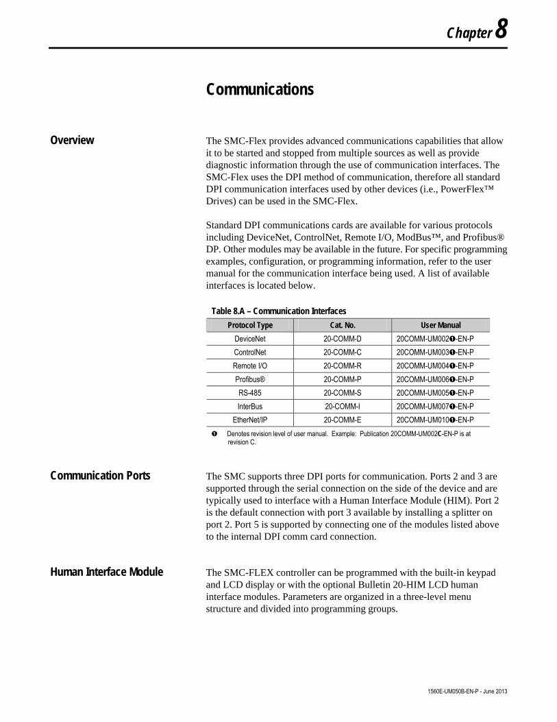
Communications
Overview The SMC-Flex provides advanced communications capabilities that allowit to be started and stopped from multiple sources as well as providediagnostic information through the use of communication interfaces. TheSMC-Flex uses the DPI method of communication, therefore all standardDPI communication interfaces used by other devices (i.e., PowerFlex™Drives) can be used in the SMC-Flex.
Standard DPI communications cards are available for various protocolsincluding DeviceNet, ControlNet, Remote I/O, ModBus™, and Profibus®DP. Other modules may be available in the future. For specific programmingexamples, configuration, or programming information, refer to the usermanual for the communication interface being used. A list of availableinterfaces is located below.
Table 8.A – Communication Interfaces
Protocol Type Cat. No. User Manual
DeviceNet 20-COMM-D 20COMM-UM002Ê-EN-P ControlNet 20-COMM-C 20COMM-UM003Ê-EN-P Remote I/O 20-COMM-R 20COMM-UM004Ê-EN-P Profibus® 20-COMM-P 20COMM-UM006Ê-EN-P RS-485 20-COMM-S 20COMM-UM005Ê-EN-P InterBus 20-COMM-I 20COMM-UM007Ê-EN-P
EtherNet/IP 20-COMM-E 20COMM-UM010Ê-EN-P Ê Denotes revision level of user manual. Example: Publication 20COMM-UM002C-EN-P is at
revision C.
Communication Ports The SMC supports three DPI ports for communication. Ports 2 and 3 aresupported through the serial connection on the side of the device and aretypically used to interface with a Human Interface Module (HIM). Port 2is the default connection with port 3 available by installing a splitter onport 2. Port 5 is supported by connecting one of the modules listed aboveto the internal DPI comm card connection.
Human Interface Module The SMC-FLEX controller can be programmed with the built-in keypadand LCD display or with the optional Bulletin 20-HIM LCD humaninterface modules. Parameters are organized in a three-level menustructure and divided into programming groups.
Chapter 8
1560E-UM050B-EN-P - June 2013

8-2 Communications
1560E-UM050B-EN-P - June 2013
Human Interface Module (cont.) Keypad Description
The functions of each programming key are described below.
Table 8.B – Keypad Descriptions
Escape Exit a menu, cancel a change to a parameter value, or acknowledge a fault/alarm.
Select Select a digit, select a bit, or enter edit mode in a parameter screen.
Up/Down Arrows
Scroll through options increase/decrease a value, or toggle a bit.
Enter Enter a menu, enter edit mode in a parameter screen, or save a change to a parameter value.
Note: If a human interface module is disconnected from the SMC-Flexcontroller while the Logic Mask is set to 1, a “Coms Loss” willoccur.
Note: For ease of programming values, after using the Enter key to edit,use the Sel key to jump to the digit that needs to be modified, thenuse the arrow keys to scroll through the digits.
The Bulletin 20-HIM LCD interface modules may be used to program andcontrol the SMC-Flex controller. The human interface modules have twosections: a display panel and a control panel. The display panel duplicatesthe 3-line, 16-character backlit LCD display and programming keypadfound on front of the SMC-Flex controller. Refer to Chapter 4 for adescription of the programming keys; refer to Appendix E for a listing ofhuman interface module catalog numbers that are compatible with thecontroller.
Note: Bulletin 20-HIM Rev3.002 or later must be utilized with theSMC-Flex.
Note: Extension cables are available up to a maximum of 10 m in totallength.
Note: A maximum of two HIM modules can be installed.
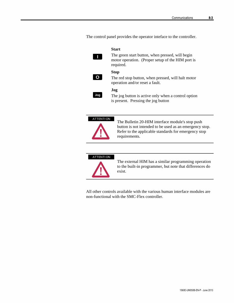
Communications 8-3
1560E-UM050B-EN-P - June 2013
The control panel provides the operator inteface to the controller.
II
Start The green start button, when pressed, will begin motor operation. (Proper setup of the HIM port is required.
OO
Stop The red stop button, when pressed, will halt motor operation and/or reset a fault.
JogJog
Jog The jog button is active only when a control option is present. Pressing the jog button
The Bulletin 20-HIM interface module's stop pushbutton is not intended to be used as an emergency stop.Refer to the applicable standards for emergency stoprequirements.
The external HIM has a similar programming operationto the built-in programmer, but note that differences doexist.
All other controls available with the various human interface modules arenon-functional with the SMC-Flex controller.
A T T E N T I O NA T T E N T I O N
A T T E N T I O NA T T E N T I O N

8-4 Communications
1560E-UM050B-EN-P - June 2013
Connecting the Human Interface Module to the Controller
Figure 8.1 shows the connection of the SMC-Flex controller to a humaninterface module. Table 8.C provides a description of each port.
See Figure 1.24 or 1.27 for the control wiring diagram that enables start-stopcontrol from a human interface module.
Port 5 – DPI Communications
Port 2
Ports 2 and 3 when two HIMsare connected with a splitter
Port 5 – DPI Communications
Port 2
Ports 2 and 3 when two HIMsare connected with a splitter
Figure 8.1 – SMC-Flex Controller with Human Interface Module
Table 8.C – Description of Ports Port # Description
1 Unused – Not available for use 2 First 20-HIM connected to SMC-Flex 3 Second 20-HIM connected to SMC-Flex 5 DPI Communication Board port
Control Enable
To enable motor control from a connected human interface module, followthe procedure below with the connected human interface module’sprogramming keys.
The Bulletin 20-HIM-LCD human interface modules with control panelscan start and stop the SMC-FLEX controller. However, the factory defaultsettings disable control commands other than Stop through the serialcommunication port.
To enable motor control from a connected human interface module orcommunication module, you must take the following programming steps:
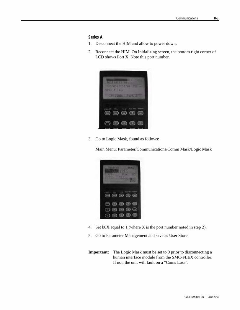
Communications 8-5
1560E-UM050B-EN-P - June 2013
Series A1. Disconnect the HIM and allow to power down.
2. Reconnect the HIM. On Initializing screen, the bottom right corner ofLCD shows Port X. Note this port number.
3. Go to Logic Mask, found as follows:
Main Menu: Parameter/Communications/Comm Mask/Logic Mask
4. Set b0X equal to 1 (where X is the port number noted in step 2).
5. Go to Parameter Management and save as User Store.
Important: The Logic Mask must be set to 0 prior to disconnecting ahuman interface module from the SMC-FLEX controller.If not, the unit will fault on a “Coms Loss”.
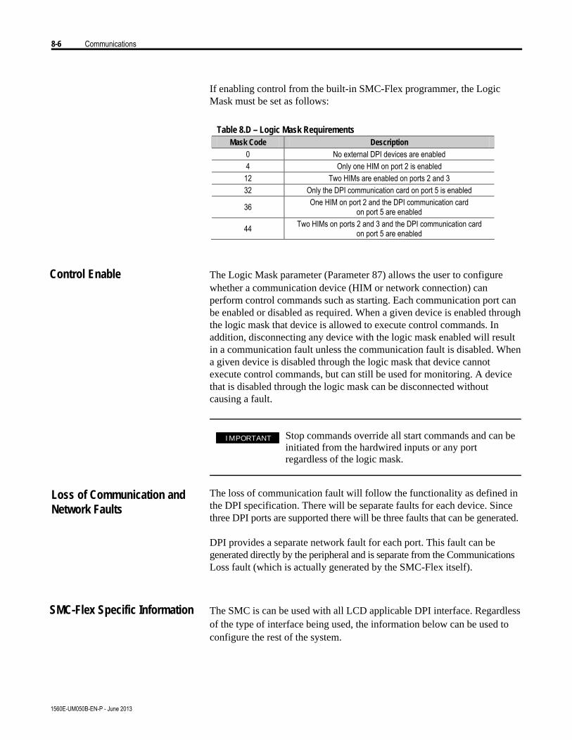
8-6 Communications
1560E-UM050B-EN-P - June 2013
If enabling control from the built-in SMC-Flex programmer, the LogicMask must be set as follows:
Table 8.D – Logic Mask Requirements Mask Code Description
0 No external DPI devices are enabled 4 Only one HIM on port 2 is enabled 12 Two HIMs are enabled on ports 2 and 3 32 Only the DPI communication card on port 5 is enabled
36 One HIM on port 2 and the DPI communication card on port 5 are enabled
44 Two HIMs on ports 2 and 3 and the DPI communication card on port 5 are enabled
Control Enable The Logic Mask parameter (Parameter 87) allows the user to configurewhether a communication device (HIM or network connection) canperform control commands such as starting. Each communication port canbe enabled or disabled as required. When a given device is enabled throughthe logic mask that device is allowed to execute control commands. Inaddition, disconnecting any device with the logic mask enabled will resultin a communication fault unless the communication fault is disabled. Whena given device is disabled through the logic mask that device cannotexecute control commands, but can still be used for monitoring. A devicethat is disabled through the logic mask can be disconnected withoutcausing a fault.
Stop commands override all start commands and can beinitiated from the hardwired inputs or any portregardless of the logic mask.
The loss of communication fault will follow the functionality as defined inthe DPI specification. There will be separate faults for each device. Sincethree DPI ports are supported there will be three faults that can be generated.
DPI provides a separate network fault for each port. This fault can begenerated directly by the peripheral and is separate from the CommunicationsLoss fault (which is actually generated by the SMC-Flex itself).
SMC-Flex Specific Information The SMC is can be used with all LCD applicable DPI interface. Regardlessof the type of interface being used, the information below can be used toconfigure the rest of the system.
I M P O R T A N TI M P O R T A N T
Loss of Communication andNetwork Faults
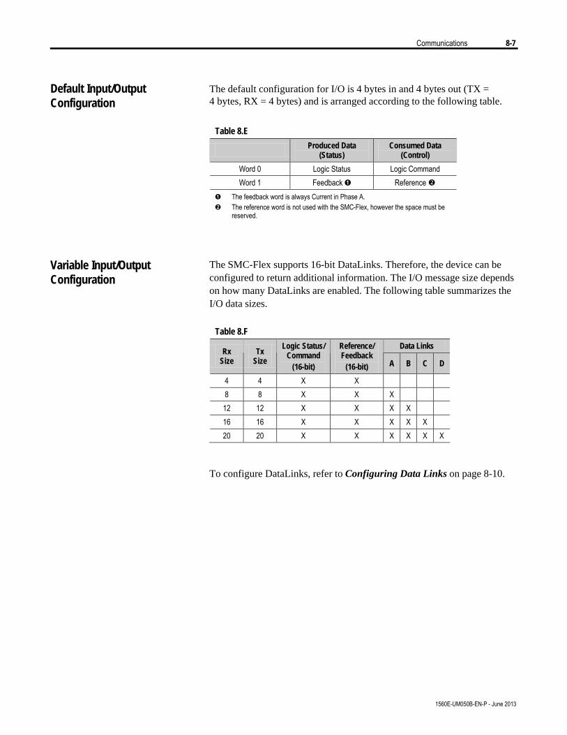
Communications 8-7
1560E-UM050B-EN-P - June 2013
The default configuration for I/O is 4 bytes in and 4 bytes out (TX =4 bytes, RX = 4 bytes) and is arranged according to the following table.
Table 8.E
Produced Data (Status)
Consumed Data (Control)
Word 0 Logic Status Logic Command Word 1 Feedback Ê Reference v
Ê The feedback word is always Current in Phase A. Ë The reference word is not used with the SMC-Flex, however the space must be
reserved.
The SMC-Flex supports 16-bit DataLinks. Therefore, the device can beconfigured to return additional information. The I/O message size dependson how many DataLinks are enabled. The following table summarizes theI/O data sizes.
Table 8.F
Data Links Rx
Size Tx
Size
Logic Status/ Command
(16-bit)
Reference/ Feedback
(16-bit) A B C D
4 4 X X 8 8 X X X 12 12 X X X X 16 16 X X X X X 20 20 X X X X X X
To configure DataLinks, refer to Configuring Data Links on page 8-10.
Default Input/OutputConfiguration
Variable Input/OutputConfiguration
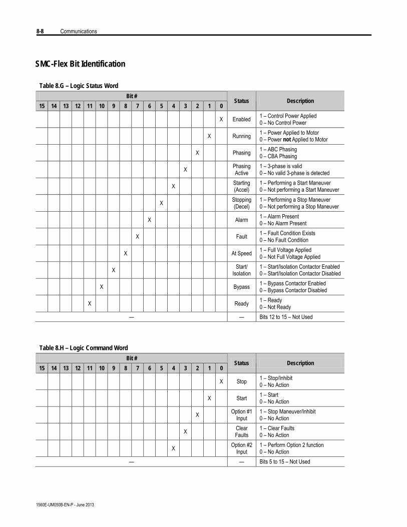
8-8 Communications
1560E-UM050B-EN-P - June 2013
SMC-Flex Bit Identification
Table 8.G – Logic Status Word
Bit #
15 14 13 12 11 10 9 8 7 6 5 4 3 2 1 0 Status Description
X Enabled 1 – Control Power Applied 0 – No Control Power
X Running 1 – Power Applied to Motor 0 – Power not Applied to Motor
X Phasing 1 – ABC Phasing 0 – CBA Phasing
X Phasing Active
1 – 3-phase is valid 0 – No valid 3-phase is detected
X Starting (Accel)
1 – Performing a Start Maneuver 0 – Not performing a Start Maneuver
X Stopping (Decel)
1 – Performing a Stop Maneuver 0 – Not performing a Stop Maneuver
X Alarm 1 – Alarm Present 0 – No Alarm Present
X Fault 1 – Fault Condition Exists 0 – No Fault Condition
X At Speed 1 – Full Voltage Applied 0 – Not Full Voltage Applied
X Start/ Isolation
1 – Start/Isolation Contactor Enabled 0 – Start/Isolation Contactor Disabled
X Bypass 1 – Bypass Contactor Enabled 0 – Bypass Contactor Disabled
X Ready 1 – Ready 0 – Not Ready
— — Bits 12 to 15 – Not Used
Table 8.H – Logic Command Word
Bit #
15 14 13 12 11 10 9 8 7 6 5 4 3 2 1 0 Status Description
X Stop 1 – Stop/Inhibit 0 – No Action
X Start 1 – Start 0 – No Action
X Option #1 Input
1 – Stop Maneuver/Inhibit 0 – No Action
X Clear Faults
1 – Clear Faults 0 – No Action
X Option #2 Input
1 – Perform Option 2 function 0 – No Action
— — Bits 5 to 15 – Not Used
Communications 8-9
1560E-UM050B-EN-P - June 2013
Reference/Feedback The SMC-Flex does not offer the analog Reference feature. The analogFeedback feature is supported and will provide Parameter 1, Current inPhase A, automatically as the feedback word.
Parameter Information A complete listing of the SMC-Flex parameters is located in Appendix B.
The parameter values stored and produced by the SMC-Flex throughcommunication are unscaled numbers. When reading or writing valuesfrom a PLC image table, it is important to apply the proper scaling factor,which is based on the number of decimal places.
Read Example
Parameter 11; Power Factor — The stored value is 85. Since this valuehas two decimal places, the value should be divided by 100. The correctlyread value is 0.85.
Write Example
Parameter 46; Motor FLC — The value which is to be written to theSMC is 75 A. Since this value has one decimal place, the value should bemultiplied by 10. The correctly written value is 750.
Display Text Unit Equivalents Some parameters have text descriptions when viewed from a HIM orthrough a communication software program such as RSNetworxÔ. Whenreceiving or sending information from a PLC each text description has anumerical equivalent. Table 8.I has an example of Parameter 44, OverloadClass, and the appropriate relationship between the text descriptor and theequivalent value. This relationship is identical for other similar parameterslocated in Appendix B.
Table 8.I
Text Descriptor Numerical Equivalent
Disabled 0 Class 10 1 Class 15 2 Class 20 3 Class 30 4
Scale Factors for PLCCommunication

8-10 Communications
1560E-UM050B-EN-P - June 2013
Configuring DataLinks DataLinks are supported in the SMC-Flex. A DataLink is a mechanismused by most drives to transfer data to and from the controller withoutusing an Explicit Message. The SMC-Flex supports 16-bit DataLinks,therefore the device can be configured to return up to four additionalpieces of information without the need for an explicit message.
Rules for Using DataLinks
• Each set of DataLink parameters in an SMC-Flex can be used by onlyone adapter. If more than one adapter is connected, multiple adaptersmust not try to use the same DataLink.
• Parameter settings in the SMC determine the data passed through theDataLink mechanism.
• When you use a DataLink to change a value, the value is not written tothe Non-Volatile Storage (NVS). The value is stored in volatile memoryand lost when the drive loses power.
Parameters 88 to 103 are used to configure the DataLinks. For additionalinformation regarding DataLinks, refer to the user manual for thecommunication interface being used.
Note: Node addressing of the DPI communication card can beprogrammed via software or a hand-held DPI HIM. The on-boardHIM cannot be used to address the communication card.
Updating Firmware The latest version of firmware and instructions for the SMC-Flex can beobtained from www.ab.com.
Note: The MV SMC-Flex must use firmware release 3.006 or later.
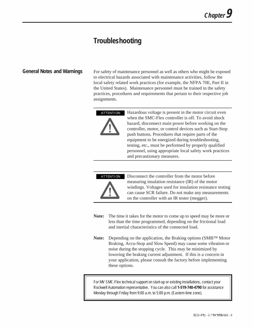
Chapter 9
Troubleshooting
General Notes and Warnings For safety of maintenance personnel as well as others who might be exposedto electrical hazards associated with maintenance activities, follow thelocal safety related work practices (for example, the NFPA 70E, Part II inthe United States). Maintenance personnel must be trained in the safetypractices, procedures and requirements that pertain to their respective jobassignments.
Hazardous voltage is present in the motor circuit evenwhen the SMC-Flex controller is off. To avoid shockhazard, disconnect main power before working on thecontroller, motor, or control devices such as Start-Stoppush buttons. Procedures that require parts of theequipment to be energized during troubleshooting,testing, etc., must be performed by properly qualifiedpersonnel, using appropriate local safety work practicesand precautionary measures.
Disconnect the controller from the motor beforemeasuring insulation resistance (IR) of the motorwindings. Voltages used for insulation resistance testingcan cause SCR failure. Do not make any measurementson the controller with an IR tester (megger).
Note: The time it takes for the motor to come up to speed may be more orless than the time programmed, depending on the frictional loadand inertial characteristics of the connected load.
Note: Depending on the application, the Braking options (SMB™ MotorBraking, Accu-Stop and Slow Speed) may cause some vibration ornoise during the stopping cycle. This may be minimized bylowering the braking current adjustment. If this is a concern inyour application, please consult the factory before implementingthese options.
For MV SMC-Flex technical support on start-up or existing installations, contact yourRockwell Automation representative. You can also call 1-519-740-4790 for assistanceMonday through Friday from 9:00 a.m. to 5:00 p.m. (Eastern time zone).
A T T E N T I O NA T T E N T I O N
A T T E N T I O NA T T E N T I O N
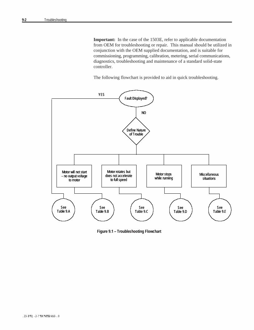
9-2 Troubleshooting
Important: In the case of the 1503E, refer to applicable documentationfrom OEM for troubleshooting or repair. This manual should be utilized inconjunction with the OEM supplied documentation, and is suitable forcommissioning, programming, calibration, metering, serial communications,diagnostics, troubleshooting and maintenance of a standard solid-statecontroller.
The following flowchart is provided to aid in quick troubleshooting.
Fault Displayed?YES
NO
Define Natureof Trouble
Motor will not start– no output voltage
to motor
Motor rotates butdoes not accelerate
to full speed
Motor stopswhile running
Miscellaneoussituations
SeeTable 9.A
SeeTable 9.B
SeeTable 9.C
SeeTable 9.D
SeeTable 9.E
Fault Displayed?YES
NO
Define Natureof Trouble
Motor will not start– no output voltage
to motor
Motor rotates butdoes not accelerate
to full speed
Motor stopswhile running
Miscellaneoussituations
SeeTable 9.A
SeeTable 9.B
SeeTable 9.C
SeeTable 9.D
SeeTable 9.E
Figure 9.1 – Troubleshooting Flowchart
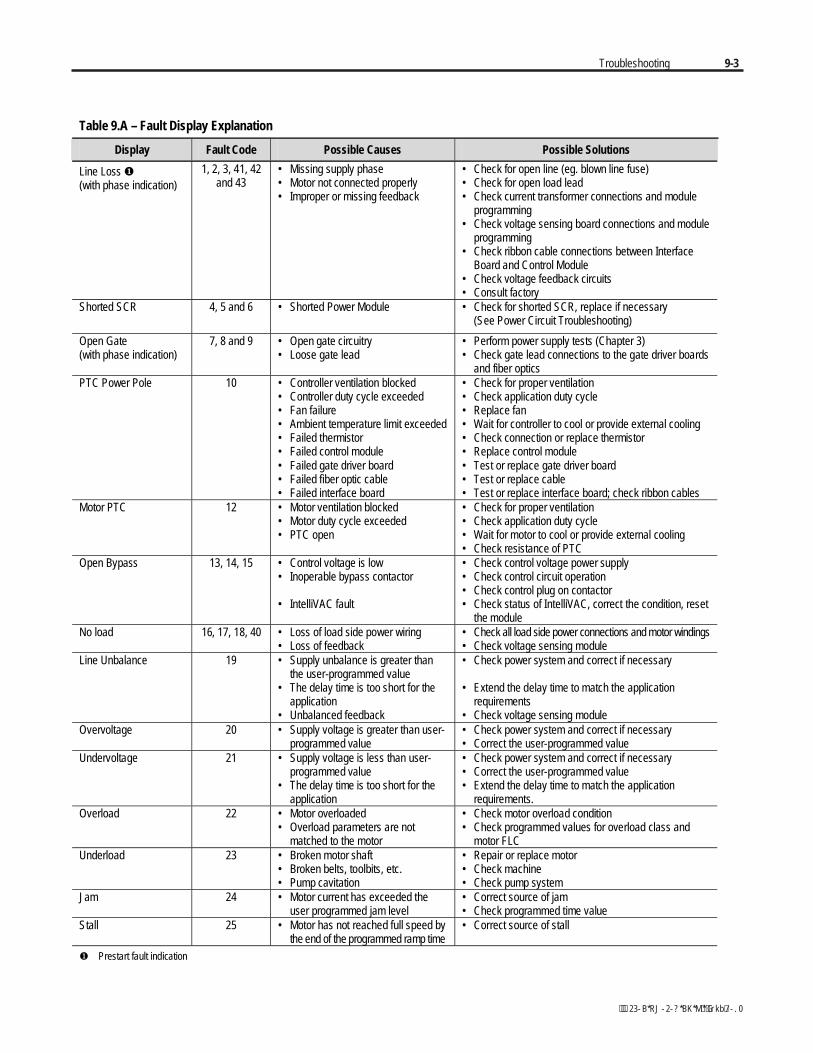
Troubleshooting 9-3
Table 9.A – Fault Display Explanation
Display Fault Code Possible Causes Possible Solutions
Line Loss (with phase indication)
1, 2, 3, 41, 42and 43
• Missing supply phase• Motor not connected properly• Improper or missing feedback
• Check for open line (eg. blown line fuse)• Check for open load lead• Check current transformer connections and module
programming• Check voltage sensing board connections and module
programming• Check ribbon cable connections between Interface
Board and Control Module• Check voltage feedback circuits• Consult factory
Shorted SCR 4, 5 and 6 • Shorted Power Module • Check for shorted SCR, replace if necessary(See Power Circuit Troubleshooting)
Open Gate(with phase indication)
7, 8 and 9 • Open gate circuitry• Loose gate lead
• Perform power supply tests (Chapter 3)• Check gate lead connections to the gate driver boards
and fiber opticsPTC Power Pole 10 • Controller ventilation blocked
• Controller duty cycle exceeded• Fan failure• Ambient temperature limit exceeded• Failed thermistor• Failed control module• Failed gate driver board• Failed fiber optic cable• Failed interface board
• Check for proper ventilation• Check application duty cycle• Replace fan• Wait for controller to cool or provide external cooling• Check connection or replace thermistor• Replace control module• Test or replace gate driver board• Test or replace cable• Test or replace interface board; check ribbon cables
Motor PTC 12 • Motor ventilation blocked• Motor duty cycle exceeded• PTC open
• Check for proper ventilation• Check application duty cycle• Wait for motor to cool or provide external cooling• Check resistance of PTC
Open Bypass 13, 14, 15 • Control voltage is low• Inoperable bypass contactor
• IntelliVAC fault
• Check control voltage power supply• Check control circuit operation• Check control plug on contactor• Check status of IntelliVAC, correct the condition, reset
the moduleNo load 16, 17, 18, 40 • Loss of load side power wiring
• Loss of feedback• Check all load side power connections and motor windings• Check voltage sensing module
Line Unbalance 19 • Supply unbalance is greater thanthe user-programmed value
• The delay time is too short for theapplication
• Unbalanced feedback
• Check power system and correct if necessary
• Extend the delay time to match the applicationrequirements
• Check voltage sensing moduleOvervoltage 20 • Supply voltage is greater than user-
programmed value• Check power system and correct if necessary• Correct the user-programmed value
Undervoltage 21 • Supply voltage is less than user-programmed value
• The delay time is too short for theapplication
• Check power system and correct if necessary• Correct the user-programmed value• Extend the delay time to match the application
requirements.Overload 22 • Motor overloaded
• Overload parameters are notmatched to the motor
• Check motor overload condition• Check programmed values for overload class and
motor FLCUnderload 23 • Broken motor shaft
• Broken belts, toolbits, etc.• Pump cavitation
• Repair or replace motor• Check machine• Check pump system
Jam 24 • Motor current has exceeded theuser programmed jam level
• Correct source of jam• Check programmed time value
Stall 25 • Motor has not reached full speed bythe end of the programmed ramp time
• Correct source of stall
Prestart fault indication
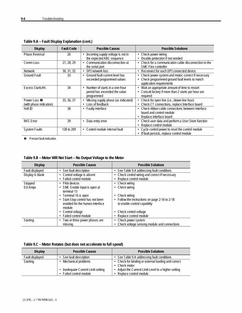
9-4 Troubleshooting
Table 9.A – Fault Display Explanation (cont.)
Display Fault Code Possible Causes Possible Solutions
Phase Reversal 26 • Incoming supply voltage is not inthe expected ABC sequence
• Check power wiring• Disable protection if not needed
Comm Loss 27, 28, 29 • Communication disconnection atthe serial port
• Check for a communication cable disconnection to theSMC-Flex controller
Network 30, 31, 32 • DPI network loss • Reconnect for each DPI connected deviceGround Fault 33 • Ground fault current level has
exceeded programmed values• Check power system and motor; correct if necessary• Check programmed ground fault levels to match
application requirementsExcess Starts/Hr. 34 • Number of starts in a one-hour
period has exceeded the valueprogrammed
• Wait an appropriate amount of time to restart• Consult factory if more than 2 starts per hour are
requiredPower Loss (with phase indication)
35, 36, 37 • Missing supply phase (as indicated)• Loss of feedback
• Check for open line (i.e., blown line fuse)• Check CT connections, replace Interface board
Hall ID 38 • Faulty interface • Check ribbon cable connections between interfaceboard and control module
• Replace interface boardNVS Error 39 • Data entry error • Check user data and perform a User Store function
• Replace control moduleSystem Faults 128 to 209 • Control module internal fault • Cycle control power to reset the control module
• If fault persists, replace control module Prestart fault indication
Table 9.B – Motor Will Not Start – No Output Voltage to the Motor
Display Possible Causes Possible Solutions
Fault displayed • See fault description • See Table 9.A addressing fault conditionsDisplay is blank • Control voltage is absent
• Failed control module• Check control wiring and correct if necessary• Replace control module
Stopped0.0 Amps
• Pilot devices• SMC Enable input is open at
terminal 13• Terminal 16 is open• Start-Stop control has not been
enabled for the human interfacemodule
• Control voltage• Failed control module
• Check wiring• Check wiring
• Check wiring• Follow the instructions on page 2-16 to 2-18
to enable control capability
• Check control voltage• Replace control module
Starting • Two or three power phases aremissing
• Check power system• Check voltage sensing module and connections
Table 9.C – Motor Rotates (but does not accelerate to full speed)
Display Possible Causes Possible Solutions
Fault displayed • See fault description • See Table 9.A addressing fault conditionsStarting • Mechanical problems
• Inadequate Current Limit setting• Failed control module
• Check for binding or external loading and correct• Check motor• Adjust the Current Limit Level to a higher setting• Replace control module
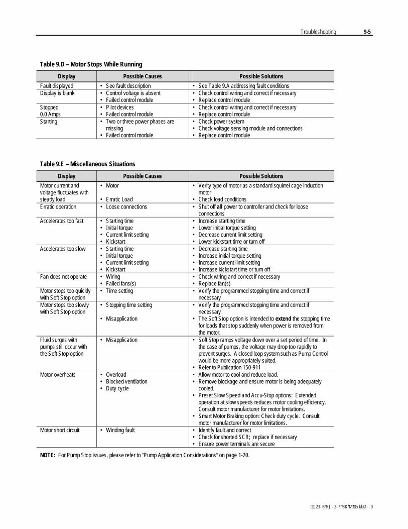
Troubleshooting 9-5
Table 9.D – Motor Stops While Running
Display Possible Causes Possible Solutions
Fault displayed • See fault description • See Table 9.A addressing fault conditionsDisplay is blank • Control voltage is absent
• Failed control module• Check control wiring and correct if necessary• Replace control module
Stopped0.0 Amps
• Pilot devices• Failed control module
• Check control wiring and correct if necessary• Replace control module
Starting • Two or three power phases aremissing
• Failed control module
• Check power system• Check voltage sensing module and connections• Replace control module
Table 9.E – Miscellaneous Situations
Display Possible Causes Possible Solutions
Motor current andvoltage fluctuates withsteady load
• Motor
• Erratic Load
• Verity type of motor as a standard squirrel cage inductionmotor
• Check load conditionsErratic operation • Loose connections • Shut off all power to controller and check for loose
connectionsAccelerates too fast • Starting time
• Initial torque• Current limit setting• Kickstart
• Increase starting time• Lower initial torque setting• Decrease current limit setting• Lower kickstart time or turn off
Accelerates too slow • Starting time• Initial torque• Current limit setting• Kickstart
• Decrease starting time• Increase initial torque setting• Increase current limit setting• Increase kickstart time or turn off
Fan does not operate • Wiring• Failed fans(s)
• Check wiring and correct if necessary• Replace fan(s)
Motor stops too quicklywith Soft Stop option
• Time setting • Verify the programmed stopping time and correct ifnecessary
Motor stops too slowlywith Soft Stop option
• Stopping time setting
• Misapplication
• Verify the programmed stopping time and correct ifnecessary
• The Soft Stop option is intended to extend the stopping timefor loads that stop suddenly when power is removed fromthe motor.
Fluid surges withpumps still occur withthe Soft Stop option
• Misapplication • Soft Stop ramps voltage down over a set period of time. Inthe case of pumps, the voltage may drop too rapidly toprevent surges. A closed loop system such as Pump Controlwould be more appropriately suited.
• Refer to Publication 150-911Motor overheats • Overload
• Blocked ventilation• Duty cycle
• Allow motor to cool and reduce load.• Remove blockage and ensure motor is being adequately
cooled.• Preset Slow Speed and Accu-Stop options: Extended
operation at slow speeds reduces motor cooling efficiency.Consult motor manufacturer for motor limitations.
• Smart Motor Braking option: Check duty cycle. Consultmotor manufacturer for motor limitations.
Motor short circuit • Winding fault • Identify fault and correct• Check for shorted SCR; replace if necessary• Ensure power terminals are secure
NOTE: For Pump Stop issues, please refer to “Pump Application Considerations” on page 1-20.
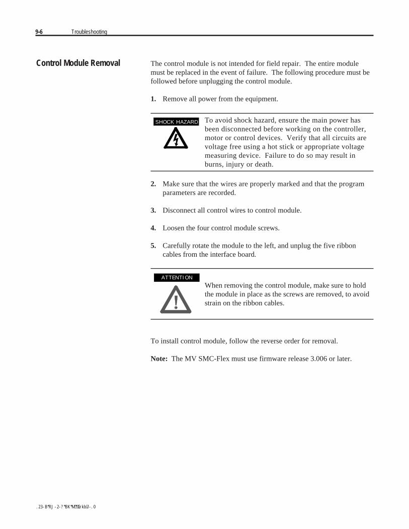
9-6 Troubleshooting
Control Module Removal The control module is not intended for field repair. The entire modulemust be replaced in the event of failure. The following procedure must befollowed before unplugging the control module.
1. Remove all power from the equipment.
To avoid shock hazard, ensure the main power hasbeen disconnected before working on the controller,motor or control devices. Verify that all circuits arevoltage free using a hot stick or appropriate voltagemeasuring device. Failure to do so may result inburns, injury or death.
2. Make sure that the wires are properly marked and that the programparameters are recorded.
3. Disconnect all control wires to control module.
4. Loosen the four control module screws.
5. Carefully rotate the module to the left, and unplug the five ribboncables from the interface board.
When removing the control module, make sure to holdthe module in place as the screws are removed, to avoidstrain on the ribbon cables.
To install control module, follow the reverse order for removal.
Note: The MV SMC-Flex must use firmware release 3.006 or later.
A T T E N T I O NA T T E N T I O N
S H O C K H A Z A R DS H O C K H A Z A R D
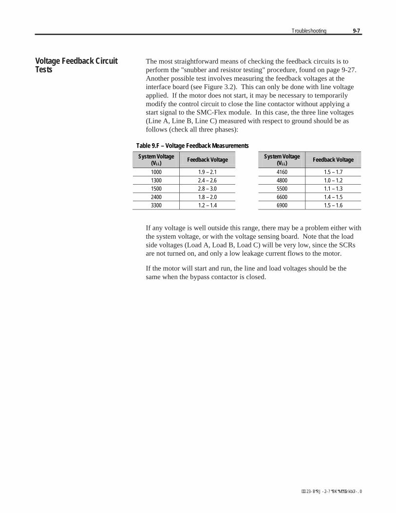
Troubleshooting 9-7
The most straightforward means of checking the feedback circuits is toperform the "snubber and resistor testing" procedure, found on page 9-27.Another possible test involves measuring the feedback voltages at theinterface board (see Figure 3.2). This can only be done with line voltageapplied. If the motor does not start, it may be necessary to temporarilymodify the control circuit to close the line contactor without applying astart signal to the SMC-Flex module. In this case, the three line voltages(Line A, Line B, Line C) measured with respect to ground should be asfollows (check all three phases):
Table 9.F – Voltage Feedback Measurements
System Voltage(VLL)
Feedback Voltage System Voltage(VLL)
Feedback Voltage
1000 1.9 – 2.1 4160 1.5 – 1.71300 2.4 – 2.6 4800 1.0 – 1.21500 2.8 – 3.0 5500 1.1 – 1.32400 1.8 – 2.0 6600 1.4 – 1.53300 1.2 – 1.4 6900 1.5 – 1.6
If any voltage is well outside this range, there may be a problem either withthe system voltage, or with the voltage sensing board. Note that the loadside voltages (Load A, Load B, Load C) will be very low, since the SCRsare not turned on, and only a low leakage current flows to the motor.
If the motor will start and run, the line and load voltages should be thesame when the bypass contactor is closed.
Voltage Feedback CircuitTests
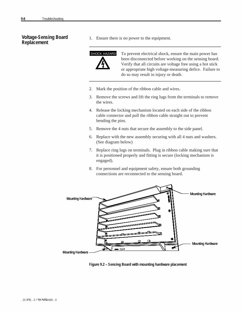
9-8 Troubleshooting
1. Ensure there is no power to the equipment.
To prevent electrical shock, ensure the main power hasbeen disconnected before working on the sensing board.Verify that all circuits are voltage free using a hot stickor appropriate high voltage-measuring defice. Failure todo so may result in injury or death.
2. Mark the position of the ribbon cable and wires.
3. Remove the screws and lift the ring lugs from the terminals to removethe wires.
4. Release the locking mechanism located on each side of the ribboncable connector and pull the ribbon cable straight out to preventbending the pins.
5. Remove the 4 nuts that secure the assembly to the side panel.
6. Replace with the new assembly securing with all 4 nuts and washers.(See diagram below)
7. Replace ring lugs on terminals. Plug in ribbon cable making sure thatit is positioned properly and fitting is secure (locking mechanism isengaged).
8. For personnel and equipment safety, ensure both groundingconnections are reconnected to the sensing board.
Mounting Hardware
Mounting Hardware
Mounting Hardware
Mounting Hardware
Mounting Hardware
Mounting Hardware
Mounting Hardware
Mounting Hardware
Figure 9.2 – Sensing Board with mounting hardware placement
Voltage-Sensing BoardReplacement
S H O C K H A Z A R DS H O C K H A Z A R D
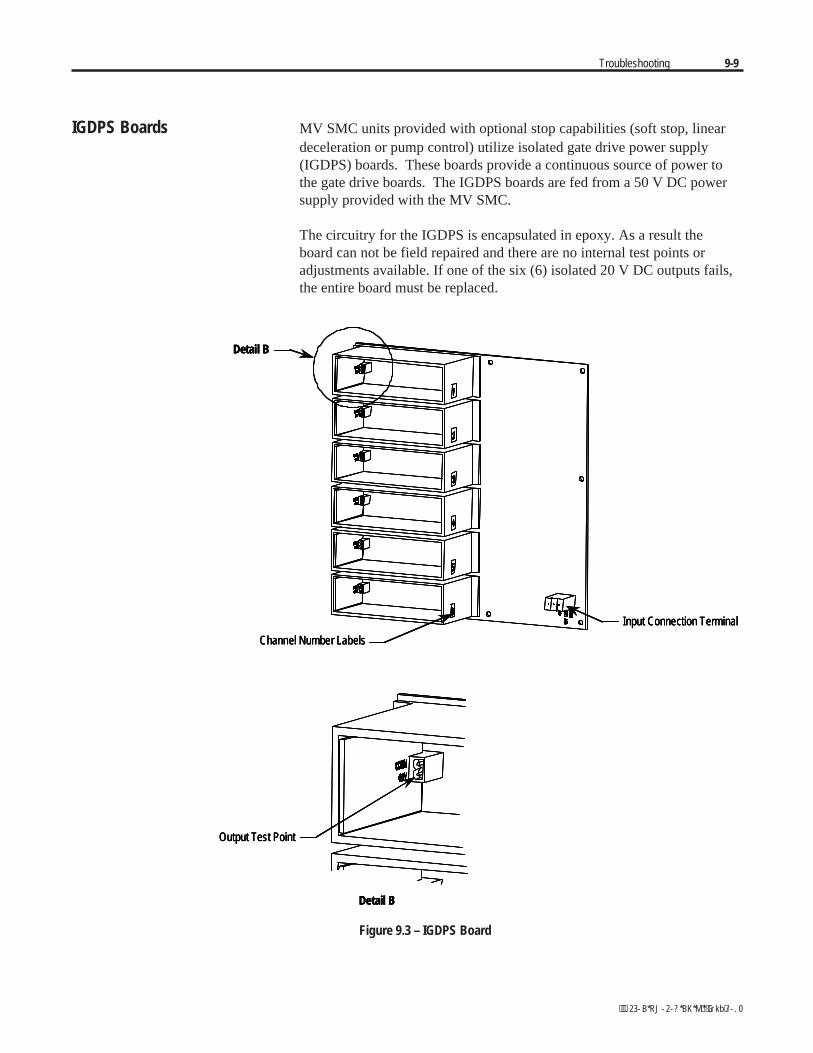
Troubleshooting 9-9
IGDPS Boards MV SMC units provided with optional stop capabilities (soft stop, lineardeceleration or pump control) utilize isolated gate drive power supply(IGDPS) boards. These boards provide a continuous source of power tothe gate drive boards. The IGDPS boards are fed from a 50 V DC powersupply provided with the MV SMC.
The circuitry for the IGDPS is encapsulated in epoxy. As a result theboard can not be field repaired and there are no internal test points oradjustments available. If one of the six (6) isolated 20 V DC outputs fails,the entire board must be replaced.
Output Test Point
Detail B
Detail B
Channel Number Labels
Input Connection Terminal
Output Test Point
Detail B
Output Test Point
Detail B
Detail B
Channel Number Labels
Input Connection Terminal
Detail B
Channel Number Labels
Input Connection Terminal
Figure 9.3 – IGDPS Board
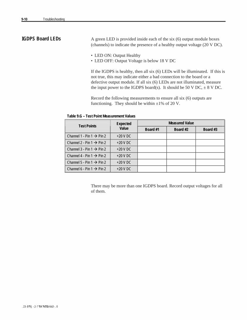
9-10 Troubleshooting
IGDPS Board LEDs A green LED is provided inside each of the six (6) output module boxes(channels) to indicate the presence of a healthy output voltage (20 V DC).
• LED ON: Output Healthy• LED OFF: Output Voltage is below 18 V DC
If the IGDPS is healthy, then all six (6) LEDs will be illuminated. If this isnot true, this may indicate either a bad connection to the board or adefective output module. If all six (6) LEDs are not illuminated, measurethe input power to the IGDPS board(s). It should be 50 V DC, ± 8 V DC.
Record the following measurements to ensure all six (6) outputs arefunctioning. They should be within ±1% of 20 V.
Table 9.G – Test Point Measurement Values
Measured ValueTest Points Expected
Value Board #1 Board #2 Board #3
Channel 1 - Pin 1 ! Pin 2 +20 V DC
Channel 2 - Pin 1 ! Pin 2 +20 V DC
Channel 3 - Pin 1 ! Pin 2 +20 V DC
Channel 4 - Pin 1 ! Pin 2 +20 V DC
Channel 5 - Pin 1 ! Pin 2 +20 V DC
Channel 6 - Pin 1 ! Pin 2 +20 V DC
There may be more than one IGDPS board. Record output voltages for allof them.

Troubleshooting 9-11
Circuit Board Replacement The replacement of printed circuit boards is straightforward, however,there are a number of precautions which must be considered whenhandling the boards.
Some circuit boards may contain CMOS componentswhich can be destroyed by static charges generated byfriction of materials made with synthetic fibres. Use ofdamaged circuit boards may also damage relatedcomponents. A grounding wrist strap is recommendedfor handling sensitive circuit boards.
1. Remove all power from the equipment.
To avoid shock hazard, ensure the main power has beendisconnected before working on the controller, motor orcontrol devices. Verify that all circuits are voltage freeusing a hot stick or appropriate voltage measuring device.Failure to do so may result in burns, injury or death.
2. Carefully detach all wires, cables and connectors, noting theirlocation and orientation. For the interface board, remove the controlmodule (see page 9-6).
The fibre-optic cables can be damaged if struck or bentsharply. They have a locking feature which requirespinching the tab on the connector and gently pullingstraight out. The component on the printed circuit boardshould be held to prevent damage.
3. For boards mounted with hardware, remove the hardware, taking carenot to drop anything onto other circuits. For boards with nylon stand-offposts, squeeze the section above the board and carefully pull the boardup and off the post.
4. Lift out the circuit board, and check that the replacement board is thecorrect part number and revision before installation (refer to Appendix D).Install the new board by replacing the hardware, or pressing down ontonylon stand offs. Connect all wires, cables and connectors. Ensurethat all switch and/or jumper settings on the new board are identical tothose on the old board, and correct for the application.
A T T E N T I O NA T T E N T I O N
A T T E N T I O NA T T E N T I O N
A T T E N T I O NA T T E N T I O N
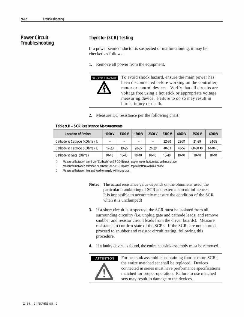
9-12 Troubleshooting
Power Circuit Thyristor (SCR) TestingTroubleshooting
If a power semiconductor is suspected of malfunctioning, it may bechecked as follows:
1. Remove all power from the equipment.
To avoid shock hazard, ensure the main power hasbeen disconnected before working on the controller,motor or control devices. Verify that all circuits arevoltage free using a hot stick or appropriate voltagemeasuring device. Failure to do so may result inburns, injury or death.
2. Measure DC resistance per the following chart:
Table 9.H – SCR Resistance Measurements
Location of Probes 1000 V 1300 V 1500 V 2300 V 3300 V 4160 V 5500 V 6900 V
Cathode to Cathode (KOhms) ➊ – – – – 22-30 23-31 21-29 24-32
Cathode to Cathode (KOhms) ➋ 17-23 19-25 20-27 21-29 40-53 43-57 60-80 64-84 ➌
Cathode to Gate (Ohms) 10-40 10-40 10-40 10-40 10-40 10-40 10-40 10-40
➊ Measured between terminals “Cathode” on SPGD Boards, upper two or bottom two within a phase.➋ Measured between terminals “Cathode” on SPGD Boards, top to bottom within a phase.➌ Measured between line and load terminals within a phase.
Note: The actual resistance value depends on the ohmmeter used, theparticular brand/rating of SCR and external circuit influences.It is impossible to accurately measure the condition of the SCRwhen it is unclamped!
3. If a short circuit is suspected, the SCR must be isolated from allsurrounding circuitry (i.e. unplug gate and cathode leads, and removesnubber and resistor circuit leads from the driver boards). Measureresistance to confirm state of the SCRs. If the SCRs are not shorted,proceed to snubber and resistor circuit testing, following thisprocedure.
4. If a faulty device is found, the entire heatsink assembly must be removed.
For heatsink assemblies containing four or more SCRs,the entire matched set shall be replaced. Devicesconnected in series must have performance specificationsmatched for proper operation. Failure to use matchedsets may result in damage to the devices.
A T T E N T I O NA T T E N T I O N
S H O C K H A Z A R DS H O C K H A Z A R D
Troubleshooting 9-13
5. Complete heatsink assemblies with matched SCRs are available as arenewal part (see Appendix D). In most cases, the assembly can bedismantled to replace the SCRs.
SCR Replacement Procedure
Note: This procedure applies to 180A and 360A units < 5000V only.
Important: Refer to OEM documentation for SCR stack location in 1503E.
A. Remove SCR Stack from Unit
For all types of SMCs, the stack requiring new SCRs must first be removedfrom the unit as follows:
1. Remove all power from the equipment.
To avoid shock hazard, ensure main power has beendisconnected before working on the controller, motor orcontrol devices. Verify that all circuits are voltage freeusing a hot stick or appropriate voltage measuringdevice. Failure to do so may result in burns, injury ordeath.
2. Service to phase A module may require removing the medium voltagedoor and swinging out the low voltage panel (for 36-inch wide, two-highcabinet only); see the low voltage panel, Fig. 9.4.
3. Unplug all fibre-optic cables from the gate-driver board. Unplug gatelead connectors and thermistor connectors. Remove leads from the leftside of the circuit board.
The grey fibre-optic cables can be damaged if struck orbent sharply. They have a locking feature which requirespinching the tab on the connector and gently pullingstraight out. The component on the printed circuit boardshould be held to prevent damage.
4. Remove gate-driver board by compressing the locking tabs of thenylon circuit board supports and carefully pulling the board off thesupports.
5. Disconnect the power cables from the terminals on the left side of theheatsink assembly. Use care not to damage components. The sharingresistors are fragile.
A T T E N T I O NA T T E N T I O N
S H O C K H A Z A R DS H O C K H A Z A R D
9-14 Troubleshooting
SCR Replacement Procedure (cont.)
6. Remove two (2) nuts at bottom front of heatsink assembly so the modulecan be removed using the pull handle. (Phase C requires angling themodule to clear the front cabinet flange). Position fibre-optic cablesand wiring so they will not be damaged as the module is removed fromthe cabinet.
7. Pull module out slowly, and slide onto a platform lift, or lift the moduleout of the cabinet.
The heatsink assembly is heavy (approx. 25 kg [55 lb]or greater). To avoid injury, always use two people toremove and handle the assembly. Place the heatsink ona cart to aid in its transport.
8. Place the module on a flat surface (see Fig. 9.7, 9.10 and 9.14). Whentilting the module, ensure that wires are not damaged.
B. Replace SCRs
Note: For 600 A units, it is mandatory that the entire stack be replaced.The high clamping force requires the factory to tighten the clamphardware. See Appendix D, Spare Parts section, for part numbers.Proceed to step C.
Note: • Refer to Figures 9.5 to 9.16.• SCR positions are numbered in succession from the top down.• The SCR cathode is at the end with the wide flange.
The SCRs must be oriented correctly with the cathodeend either up or down, depending on the specific assem-bly. Note the orientation before removing the SCRs, andrefer to the detail in the appropriate figure in this chapter.
1. Remove the shorting bar. Measure the resistance between adjacentheatsinks to determine which SCR(s) is (are) shorted. Assemblies withfour or six SCRs must use matched sets. See Figures 9.8 and 9.14 forthe position of the matched sets. If an SCR from each set is shorted, allof the SCRs in the module must be replaced. A properly functionningSCR will measure in excess of 100 kilohms from anode to cathode,and 10-40 ohms from gate to cathode.
Power CircuitTroubleshooting (cont.)
A T T E N T I O NA T T E N T I O N
A T T E N T I O NA T T E N T I O N
Troubleshooting 9-15
SCR Replacement Procedure (cont.)
Important: DO NOT loosen any of the nuts on the fiber rods on eitherside of the clamp bars. They must remain as they are to maintain squareness.See Figures 9.6, 9.9 and 9.15.
2. Loosen the clamp by rotating the centre nut below the indicator washerat the top end of the clamp. Refer to Figures 9.6, 9.9 and 9.15.
As the centre nut is rotated, the entire spring assembly is retractedfrom the top heatsink. Continue to retract until there is a gap ofapproximately 6 mm (0.25 in).
3. The heatsinks may now be spread apart to allow removal of the SCRs.
4. Apply a thin film of Electrical Joint Compound (supplied) to bothfaces of the new SCRs.
5. Place the new SCRs in position starting from the top and pushing theheat sinks together as you proceed down the stack. Make sure theSCRs are positioned and oriented properly. Refer to Figures 9.7, 9.10,and 9.16.
6. Ensure that the SCRs are properly seated on the locating pins in theheatsinks and rotate each SCR so that the leads are oriented toward thefront right side of the assembly.
7. Advance the centre nut until the spring assembly engages the topheatsink. Make sure the clamp is properly seated on the locating pinsin the top and bottom heatsinks before beginning to tighten.
8. Tighten the centre nut until the indicator washer becomes loose withsome friction. The clamp is now at the proper force and must not beclamped any tighter. If the indicator washer becomes too loose (nofriction), back the centre nut off slowly until the washer is loose withsome friction.
9. Replace the shorting bar. Torque hardware to 30 N-m (20 ft-lb). For3/8-in. hardware in the 'T' slots of aluminum heatsinks, the recommendedtorque is 22 N-m (16 ft-lb). Do not overtorque these connnections asthe slots will be damaged and the connection will be compromised.

9-16 Troubleshooting
Power Circuit SCR Replacement Procedure (cont.)Troubleshooting (cont.)
C. Install Refurbished Stack
1. Inspect all connections on the module. Inspect wire insulation andcomponents for damage.
2. Install the module in the cabinet. Watch for power cables and fibre-opticcables as module is slid into place. Tighten locking nuts at the bottomof the module.
3. Connect power cables and tighten hardware to 30 N-m (20 ft-lb).
4. Install gate-driver board, ensuring that the locking tabs on the nyloncircuit board supports are all engaged. Plug in thermistor and gateconnectors and reconnect wires to the left side of the board. Plug inthe fibre-optic cables.
5. Make sure all connections are secure. Perform resistance checksaccording to instructions on "Thyristor (SCR) Testing" (page 9-12),and test gate-drive circuits by performing power supply tests inChapter 3 (page 3-6).
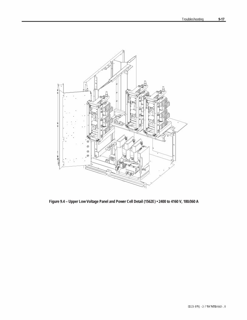
Troubleshooting 9-17
Figure 9.4 – Upper Low Voltage Panel and Power Cell Detail (1562E) • 2400 to 4160 V, 180/360 A
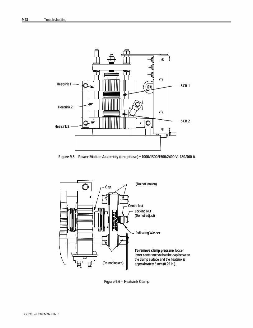
9-18 Troubleshooting
Heatsink 3
Heatsink 2
Heatsink 1
SCR 2
SCR 1
Heatsink 3
Heatsink 2
Heatsink 1
SCR 2
SCR 1
Figure 9.5 – Power Module Assembly (one phase) • 1000/1300/1500/2400 V, 180/360 A
Gap
Centre Nut
(Do not loosen)
Indicating Washer
Locking Nut(Do not adjust)
(Do not loosen)
To remove clamp pressure, loosenlower center nut so that the gap betweenthe clamp surface and the heatsink isapproximately 6 mm (0.25 in.).
Gap
Centre Nut
(Do not loosen)
Indicating Washer
Locking Nut(Do not adjust)
(Do not loosen)
To remove clamp pressure, loosenlower center nut so that the gap betweenthe clamp surface and the heatsink isapproximately 6 mm (0.25 in.).
Figure 9.6 – Heatsink Clamp
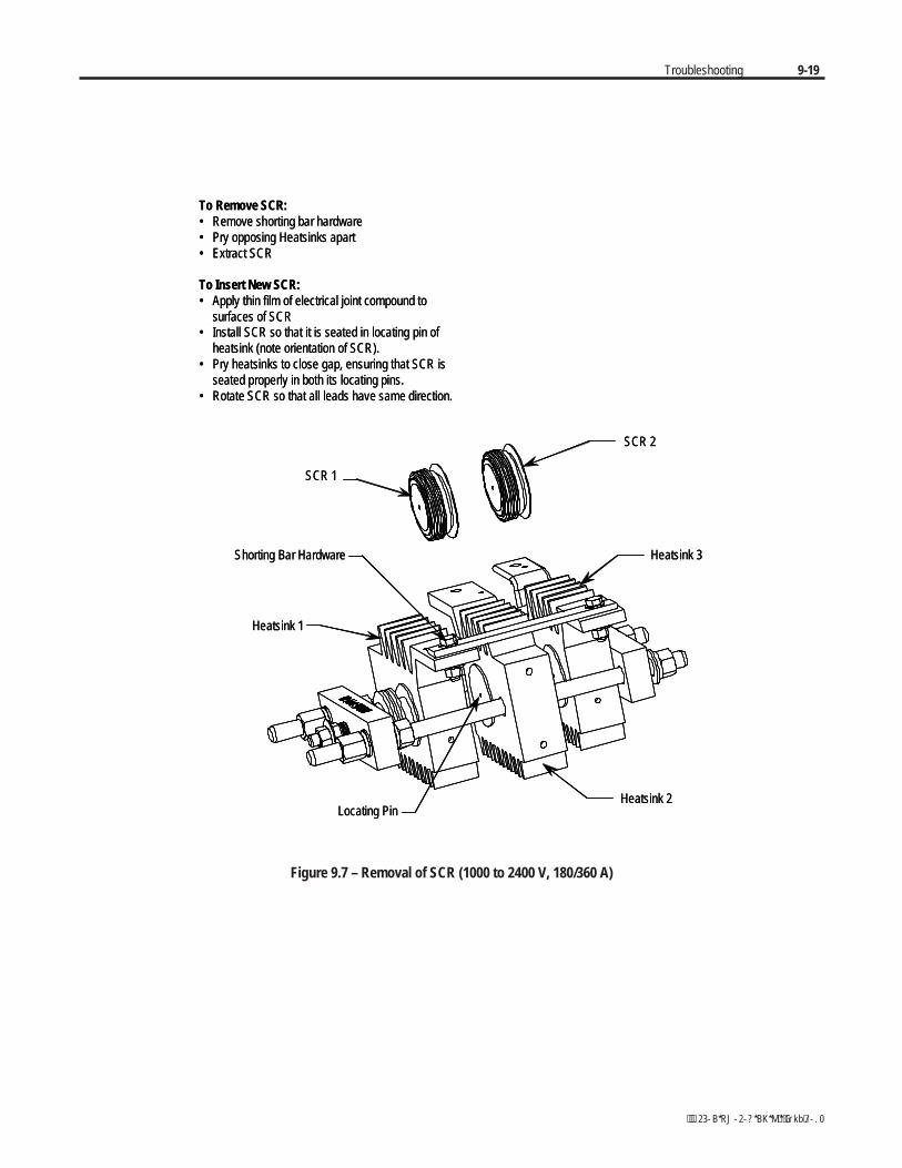
Troubleshooting 9-19
To Remove SCR:• Remove shorting bar hardware• Pry opposing Heatsinks apart• Extract SCR
To Insert New SCR:• Apply thin film of electrical joint compound to
surfaces of SCR• Install SCR so that it is seated in locating pin of
heatsink (note orientation of SCR).• Pry heatsinks to close gap, ensuring that SCR is
seated properly in both its locating pins.• Rotate SCR so that all leads have same direction.
Shorting Bar Hardware
SCR 1
Heatsink 2
Heatsink 1
Locating Pin
Heatsink 3
SCR 2
Figure 9.7 – Removal of SCR (1000 to 2400 V, 180/360 A)
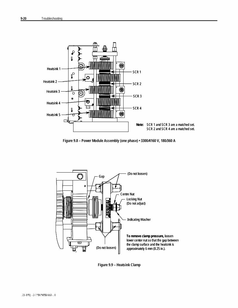
9-20 Troubleshooting
Heatsink 1SCR 1
SCR 2
SCR 3
SCR 4
Heatsink 2
Heatsink 3
Heatsink 4
Heatsink 5
Note: SCR 1 and SCR 3 are a matched set.SCR 2 and SCR 4 are a matched set.
Heatsink 1SCR 1
SCR 2
SCR 3
SCR 4
Heatsink 2
Heatsink 3
Heatsink 4
Heatsink 5
Note: SCR 1 and SCR 3 are a matched set.SCR 2 and SCR 4 are a matched set.
Figure 9.8 – Power Module Assembly (one phase) • 3300/4160 V, 180/360 A
Gap
Centre Nut
(Do not loosen)
Indicating Washer
Locking Nut(Do not adjust)
(Do not loosen)
To remove clamp pressure, loosenlower center nut so that the gap betweenthe clamp surface and the heatsink isapproximately 6 mm (0.25 in.).
Gap
Centre Nut
(Do not loosen)
Indicating Washer
Locking Nut(Do not adjust)
(Do not loosen)
To remove clamp pressure, loosenlower center nut so that the gap betweenthe clamp surface and the heatsink isapproximately 6 mm (0.25 in.).
Figure 9.9 – Heatsink Clamp
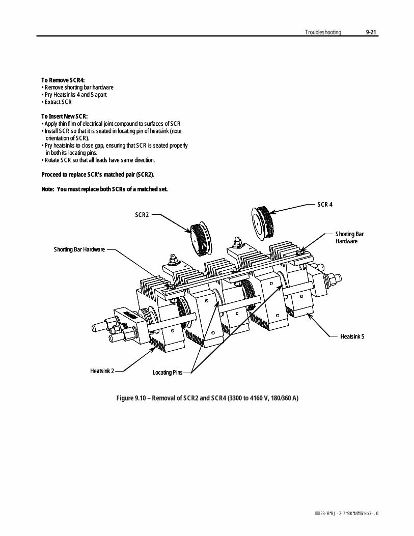
Troubleshooting 9-21
To Remove SCR4:• Remove shorting bar hardware• Pry Heatsinks 4 and 5 apart• Extract SCR
To Insert New SCR:• Apply thin film of electrical joint compound to surfaces of SCR• Install SCR so that it is seated in locating pin of heatsink (note
orientation of SCR).• Pry heatsinks to close gap, ensuring that SCR is seated properly
in both its locating pins.• Rotate SCR so that all leads have same direction.
Proceed to replace SCR’s matched pair (SCR2).
Note: You must replace both SCRs of a matched set.
Shorting BarHardware
SCR 4
Shorting Bar Hardware
Heatsink 2
Heatsink 5
SCR2
Locating Pins
Shorting BarHardware
SCR 4
Shorting Bar Hardware
Heatsink 2
Heatsink 5
SCR2
Locating Pins
Figure 9.10 – Removal of SCR2 and SCR4 (3300 to 4160 V, 180/360 A)
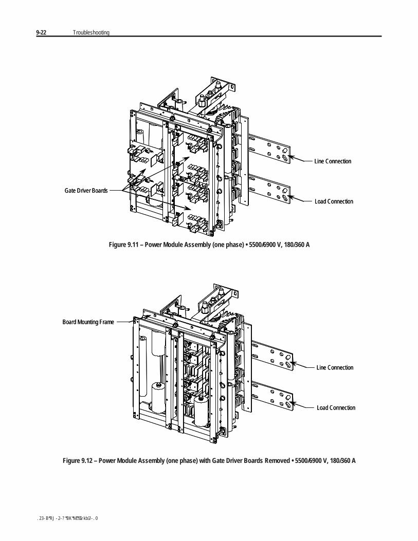
9-22 Troubleshooting
Gate Driver Boards
Line Connection
Load Connection
Gate Driver Boards
Line Connection
Load Connection
Figure 9.11 – Power Module Assembly (one phase) • 5500/6900 V, 180/360 A
Board Mounting Frame
Line Connection
Load Connection
Board Mounting Frame
Line Connection
Load Connection
Figure 9.12 – Power Module Assembly (one phase) with Gate Driver Boards Removed • 5500/6900 V, 180/360 A
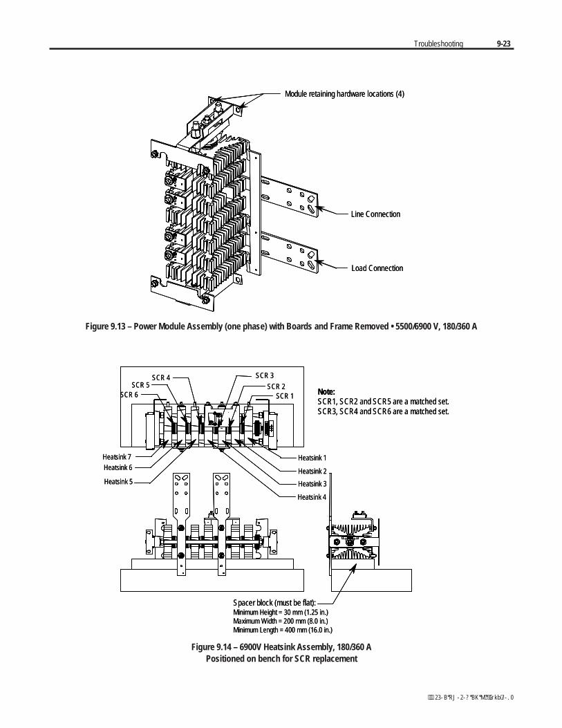
Troubleshooting 9-23
Module retaining hardware locations (4)
Line Connection
Load Connection
Module retaining hardware locations (4)
Line Connection
Load Connection
Figure 9.13 – Power Module Assembly (one phase) with Boards and Frame Removed • 5500/6900 V, 180/360 A
Heatsink 4
Heatsink 6
Heatsink 3
Heatsink 2
Heatsink 1
Note:SCR1, SCR2 and SCR5 are a matched set.SCR3, SCR4 and SCR6 are a matched set.
SCR 2SCR 1
SCR 4 SCR 3SCR 5
SCR 6
Heatsink 5
Heatsink 7
Spacer block (must be flat):Minimum Height = 30 mm (1.25 in.)Maximum Width = 200 mm (8.0 in.)Minimum Length = 400 mm (16.0 in.)
Figure 9.14 – 6900V Heatsink Assembly, 180/360 APositioned on bench for SCR replacement
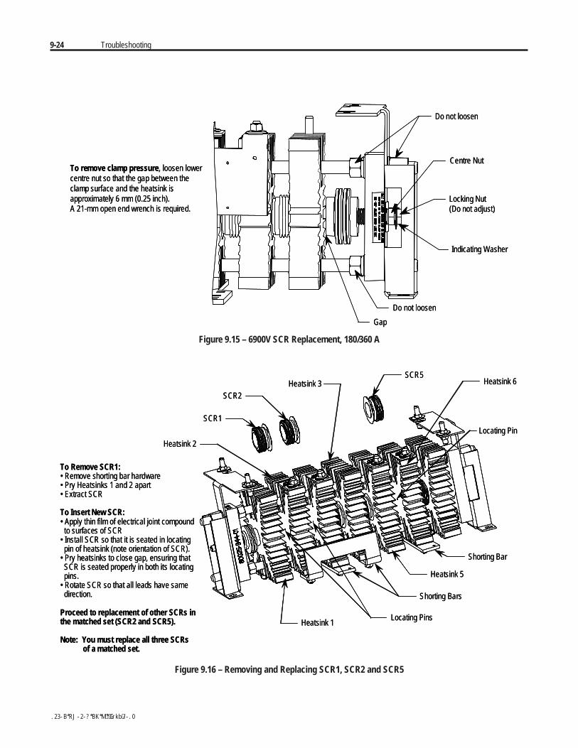
9-24 Troubleshooting
Do not loosen
Centre Nut
Locking Nut(Do not adjust)
Indicating Washer
Do not loosen
Gap
To remove clamp pressure, loosen lowercentre nut so that the gap between theclamp surface and the heatsink isapproximately 6 mm (0.25 inch).A 21-mm open end wrench is required.
Do not loosen
Centre Nut
Locking Nut(Do not adjust)
Indicating Washer
Do not loosen
Gap
To remove clamp pressure, loosen lowercentre nut so that the gap between theclamp surface and the heatsink isapproximately 6 mm (0.25 inch).A 21-mm open end wrench is required.
Figure 9.15 – 6900V SCR Replacement, 180/360 A
To Remove SCR1:• Remove shorting bar hardware• Pry Heatsinks 1 and 2 apart• Extract SCR
To Insert New SCR:• Apply thin film of electrical joint compoundto surfaces of SCR
• Install SCR so that it is seated in locatingpin of heatsink (note orientation of SCR).
• Pry heatsinks to close gap, ensuring thatSCR is seated properly in both its locatingpins.
• Rotate SCR so that all leads have samedirection.
Proceed to replacement of other SCRs inthe matched set (SCR2 and SCR5).
Note: You must replace all three SCRsof a matched set.
Heatsink 6
Heatsink 1Locating Pins
SCR5
Locating Pin
Heatsink 5
Heatsink 2
SCR1
SCR2Heatsink 3
Shorting Bars
Shorting Bar
Figure 9.16 – Removing and Replacing SCR1, SCR2 and SCR5
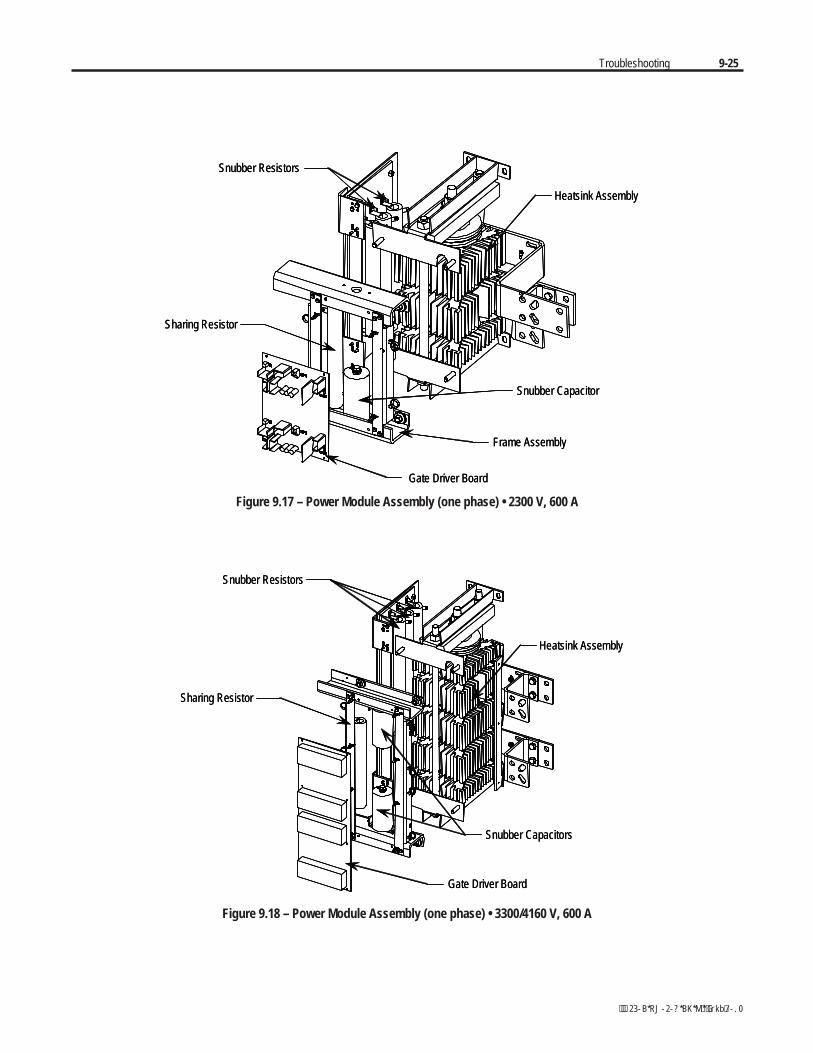
Troubleshooting 9-25
Heatsink Assembly
Snubber Capacitor
Frame Assembly
Gate Driver Board
Sharing Resistor
Snubber Resistors
Heatsink Assembly
Snubber Capacitor
Frame Assembly
Gate Driver Board
Sharing Resistor
Snubber Resistors
Figure 9.17 – Power Module Assembly (one phase) • 2300 V, 600 A
Heatsink Assembly
Snubber Capacitors
Sharing Resistor
Gate Driver Board
Snubber Resistors
Heatsink Assembly
Snubber Capacitors
Sharing Resistor
Gate Driver Board
Snubber Resistors
Figure 9.18 – Power Module Assembly (one phase) • 3300/4160 V, 600 A
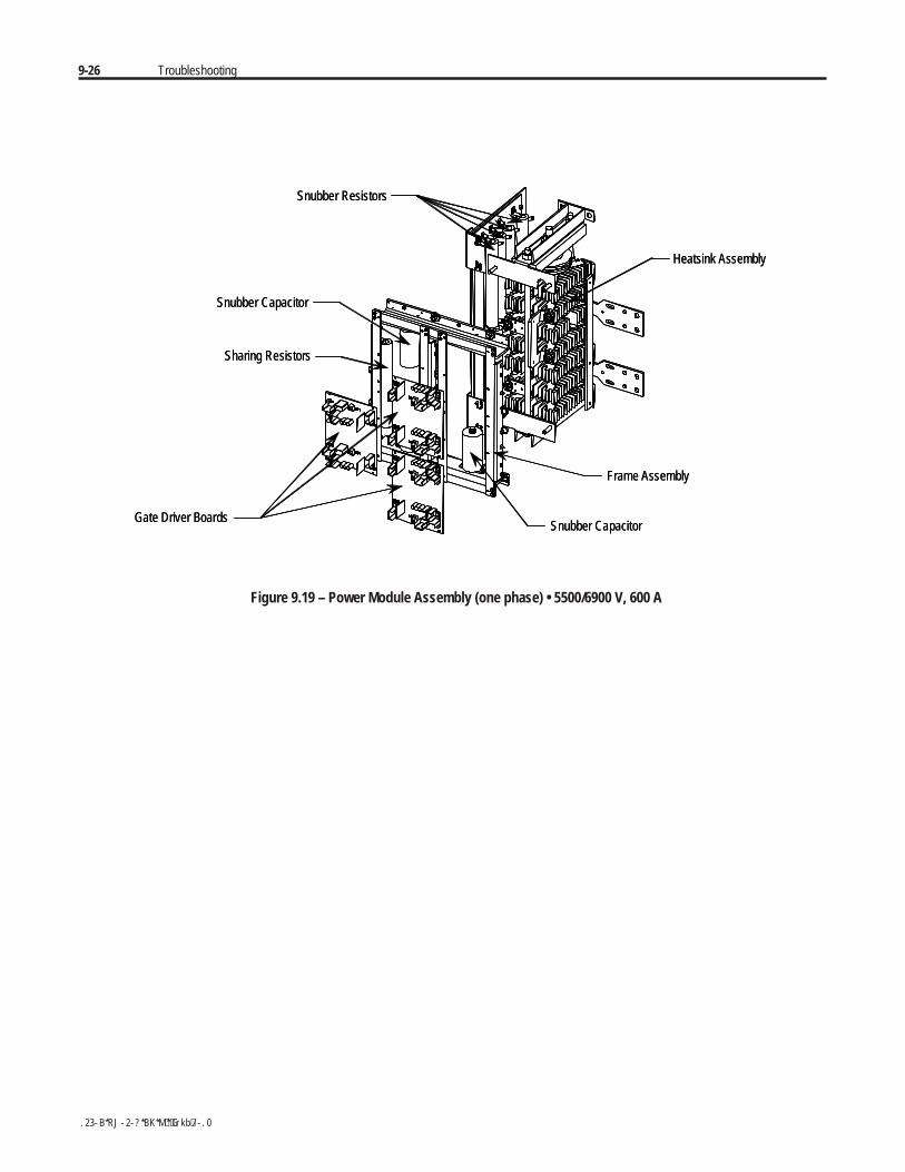
9-26 Troubleshooting
Heatsink Assembly
Snubber CapacitorGate Driver Boards
Frame Assembly
Snubber Resistors
Sharing Resistors
Snubber Capacitor
Heatsink Assembly
Snubber CapacitorGate Driver Boards
Frame Assembly
Snubber Resistors
Sharing Resistors
Snubber Capacitor
Figure 9.19 – Power Module Assembly (one phase) • 5500/6900 V, 600 A
Troubleshooting 9-27
If the resistance checks from the Thyristor testing section were abnormaland the thyristors checked out OK, there may be a problem in the snubberor resistor circuits.
1. Remove all power from the equipment.
To avoid shock hazard, ensure main power has beendisconnected before working on the controller, motor orcontrol devices. Verify that all circuits are voltage freeusing a hot stick or appropriate voltage measuringdevice. Failure to do so may result in burns, injury ordeath.
2. Check the snubber components and sharing resistors by isolating themand measuring values as follows (See Figures 9.21 to 9.26):
RS 60 Ω (180 and 360A)30 Ω (600A)
CS 0.5 or 0.68 µF (180 and 360A)1.0 µF (600A)
RRx 32.5 k Ω total, taps at 2.5 k Ω from each end(x = 1, 2 or 3)
Replace any out-of-spec components. See Renewal Parts listing inAppendix D.
3. If the snubbers and sharing resistors are within tolerances, check theresistance of the voltage sensing module (refer to Figure 9.20).Remove the ribbon connector from J1 by pressing down on the lockingtabs then gently pulling the connector out. Take note of which tap thewhite high voltage wires are connected to, then remove them (L1, T1,L2, T2, L3, T3). Measure the resistance between each tap and theground connection, and compare to the values in Figure 9.20.
S H O C K H A Z A R DS H O C K H A Z A R D
Snubber and Resistor CircuitTesting
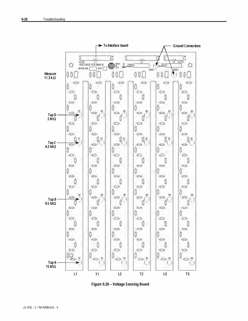
9-28 Troubleshooting
To Interface board Ground Connections
Measure11.3 k Ω
Tap D2 M Ω
Tap C4.3 M Ω
Tap B9.5 M Ω
Tap A15 M Ω
VOLTAGE FEEDBACK
21
2423
2423
109
80190-258- REV
MADEINUSA
21
21
SERIALNUMBER
PARTNUMBER
GND2GND1
WW
J1 J2 J3
1D 2D 3D 4D 5D 6D
1C 2C 3C 4C 5C 6C
1B 2B 3B 4B 5B 6B
1A 2A 3A 4A 5A 6A
L1 T1 L2 T2 L3 T3
To Interface board Ground Connections
Measure11.3 k Ω
Tap D2 M Ω
Tap C4.3 M Ω
Tap B9.5 M Ω
Tap A15 M Ω
VOLTAGE FEEDBACK
21
2423
2423
109
80190-258- REV
MADEINUSA
21
21
SERIALNUMBER
PARTNUMBER
GND2GND1
WWWW
J1 J2 J3
1D 2D 3D 4D 5D 6D
1C 2C 3C 4C 5C 6C
1B 2B 3B 4B 5B 6B
1A 2A 3A 4A 5A 6A
L1 T1 L2 T2 L3 T3
Figure 9.20 – Voltage Sensing Board
Troubleshooting 9-29
Measure across R36, R73, R110, R147, R184 and R221 located at thebottom of each leg of the module. The resistance should be 11.3 kohm.(The two ground connections must be connected to ground, or to eachother if the module has been removed.)
If the values for each leg vary by more than 1%, the voltage sensingmodule may need to be replaced. See Renewal Parts listing inAppendix D, and refer to procedure on page 9-8.
Grounds must be reconnected on the voltage sensingboards. Failure to do so may result in injury, death ordamage to equipment.
Note: The white high voltage wires must be connected to the correct tapon each leg of the voltage sensing module. Failure to do so may result inequipment damage.
The ribbon cable must be connected to J1 only on the voltage sensingboard or the equipment will not function.
4. When repairs are complete, re-assemble all parts, check all fasteners,and verify all connections are correct and tight. Make sure all barriersand mechanical parts are in place and secured.
Make sure ground wires from the Voltage SensingModule are securely connected to the ground bar in thelow voltage panel. Failure to do so may result in severeinjury or equipment damage.
5. Repeat Thyristor (SCR) resistance checks (page 9-12) and PowerSupply Tests (page 3-7).
A T T E N T I O NA T T E N T I O N
A T T E N T I O NA T T E N T I O N

9-30 Troubleshooting
Snubber Resistor Replacement When replacing the ceramic wire-wound type snubber resistors, usecaution when handling the parts. The resistor element is under a thincoating on the ceramic tube, and it may be damaged if dropped, struck orscraped.
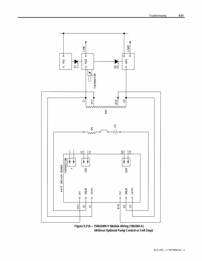
Troubleshooting 9-31
Figure 9.21A – 1500/2400 V Module Wiring (180/360 A) (Without Optional Pump Control or Soft Stop)
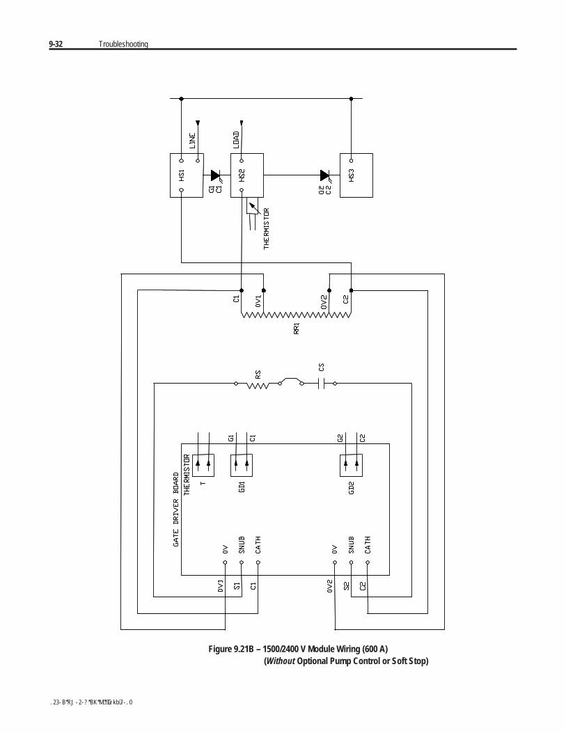
9-32 Troubleshooting
Figure 9.21B – 1500/2400 V Module Wiring (600 A) (Without Optional Pump Control or Soft Stop)
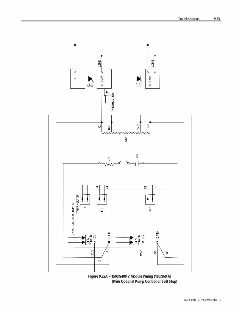
Troubleshooting 9-33
Figure 9.22A – 1500/2400 V Module Wiring (180/360 A) (With Optional Pump Control or Soft Stop)
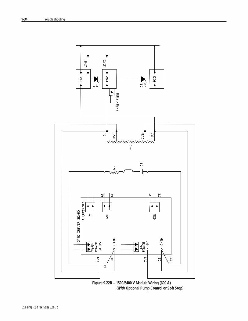
9-34 Troubleshooting
Figure 9.22B – 1500/2400 V Module Wiring (600 A) (With Optional Pump Control or Soft Stop)
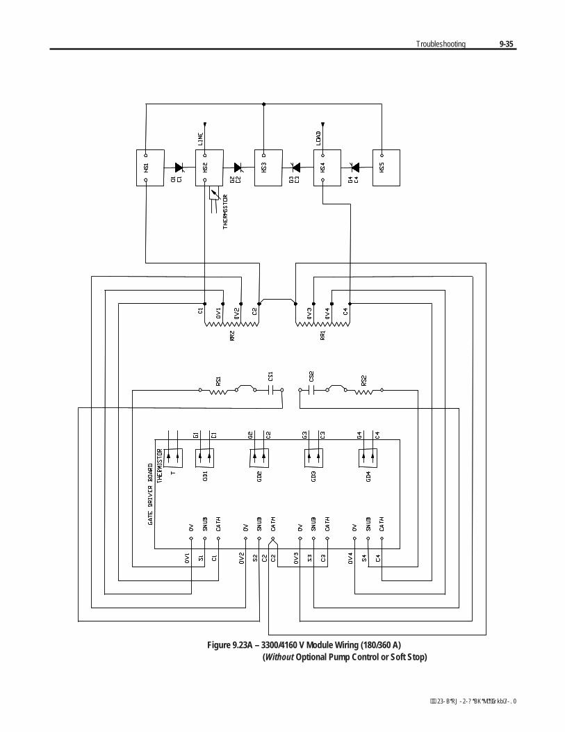
Troubleshooting 9-35
Figure 9.23A – 3300/4160 V Module Wiring (180/360 A) (Without Optional Pump Control or Soft Stop)
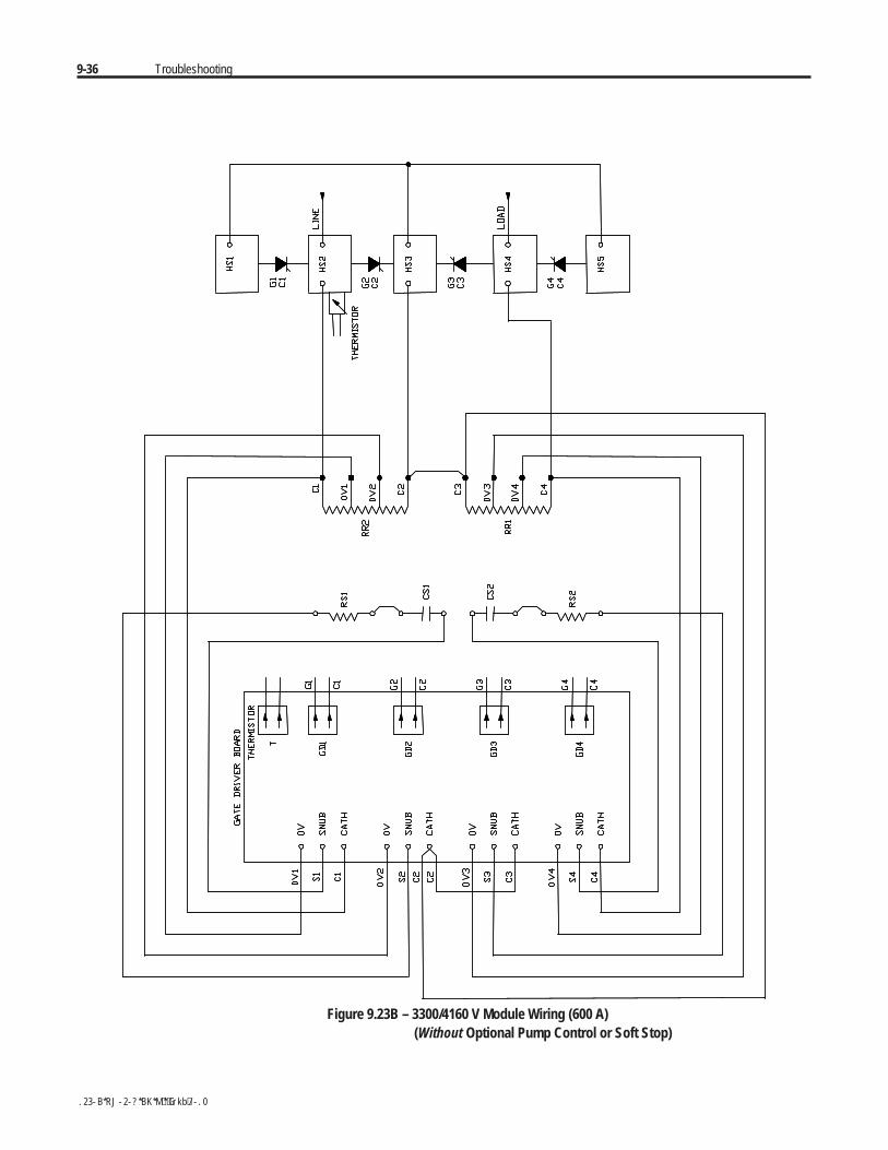
9-36 Troubleshooting
Figure 9.23B – 3300/4160 V Module Wiring (600 A) (Without Optional Pump Control or Soft Stop)

Troubleshooting 9-37
Figure 9.24A – 3300/4160 V Module Wiring (180/360 A) (With Optional Pump Control or Soft Stop)
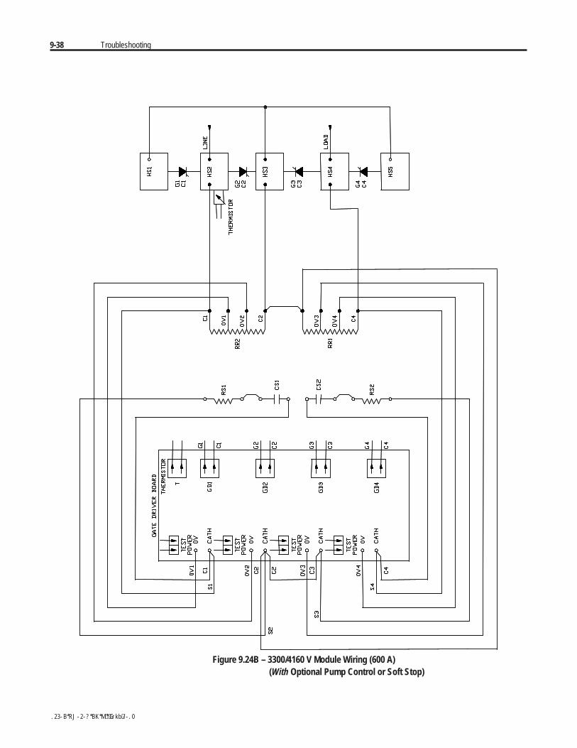
9-38 Troubleshooting
Figure 9.24B – 3300/4160 V Module Wiring (600 A) (With Optional Pump Control or Soft Stop)
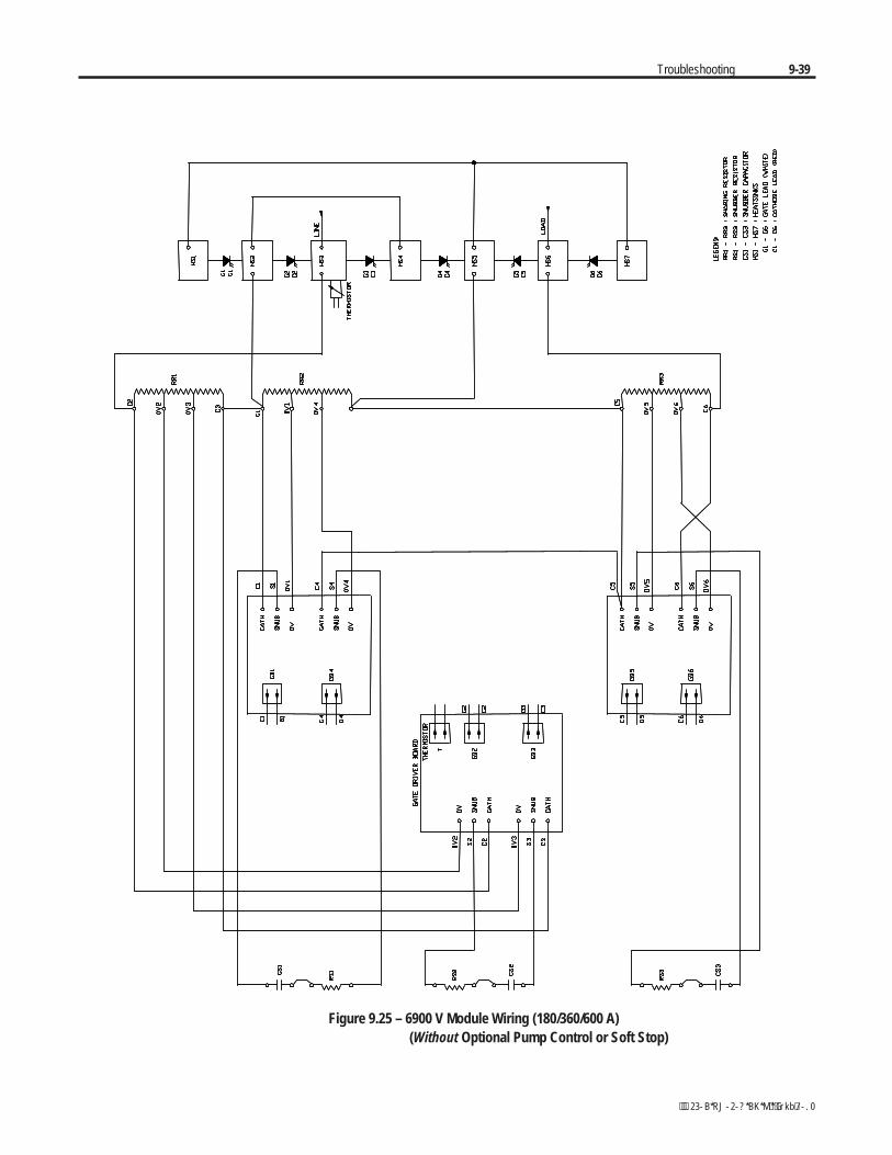
Troubleshooting 9-39
Figure 9.25 – 6900 V Module Wiring (180/360/600 A) (Without Optional Pump Control or Soft Stop)

9-40 Troubleshooting
Figure 9.26 – 6900 V Module Wiring (180/360/600 A) (With Optional Pump Control or Soft Stop)
Chapter 10
Maintenance
Safety and Preventative The Maintenance Technician should become familiar with the layout andbe aware of the basic system parameters. Only qualified technicians shouldbe allowed to work with this equipment under competent supervision.
General housekeeping is the key to maintaining power electronic andelectrical equipment. They are to be kept as dust free as possible. Ascheduled program of inspection will reduce the possibility of problems.
Servicing energized industrial control equipment canbe hazardous. Severe injury or death can result fromelectrical shock, burn, or unintended actuation ofcontrolled equipment. Recommended practice is todisconnnect and lock out control equipment frompower sources, and allow any stored energy in capaci-tors to dissipate. If it is necessary to work in thevicinity of energized equipment, the safety relatedwork practices of NFPA 70E, Electrical SafetyRequirements for Employee Workplaces, must befollowed.
Periodic Inspection Note: For OEM-supplied components, refer to documentation provided bythe OEM for recommended periodic maintenance procedures.
Industrial control equipment should be inspected periodically. Inspectionintervals should be based on environmental and operating conditions, andadjusted as indicated by experience. An initial inspection, within 3 or 4months after installation, is suggested. Applicable parts of the followingguidelines should be used:
Contamination
If inspection reveals that dust, moisture or other contamination has reachedthe control equipment, the source must be eliminated. This could indicatean incorrect or ineffective enclosure, unsealed enclosure openings (conduitor other) or incorrect operating procedures. Dirty, wet or contaminated partsmust be replaced unless they can be cleaned effectively by vacuuming orwiping.
1560E-UM050B-EN-P - June 2013
A T T E N T I O NA T T E N T I O N
10-2 Maintenance
1560E-UM050B-EN-P - June 2013
Periodic Inspection (cont.) Allen-Bradley magnetic starters, contactors and relaysare designed to operate without lubrication – do notlubricate these devices since oil or grease on the poleface (mating surfaces) of the operating magnet maycause the device to stick in the "ON" mode. Erraticoperation can result with injury or death.
Some parts of other devices are factory lubricated – if lubrication duringuse or maintenance of these devices is needed, it will be specified intheir individual instructions. If in doubt, consult the nearest RockwellAutomation sales office for information.
Vacuum Bottles
The contacts in a vacuum bottle cannot be seen or examined directly.They rely on the high vacuum to operate properly and to interrupt current.Visually inspect the wear of the main contacts with the contacts closed.When any part of the wear indicator, located on the front side of the hexshaft, moves up into the bearing, replace all three vacuum bottles (seeVacuum Contactor User Manual).
The vacuum level should be tested periodically by applying high voltagealternating current across the open bottle using a vacuum tester or Hi-Potequipment (see Vacuum Contactor User Manual).
Terminals
Loose connections can cause overheating that can lead to equipmentmalfunction or failure. Check the tightness of all terminals and bus barconnections and securely tighten any loose connections. Replace anyparts or wiring damaged by overheating.
Coils
If a coil exhibits evidence of overheating (cracked, melted or burnedinsulation), it must be replaced. In that event, check for and correctovervoltage or undervoltage conditions, which can cause coil failure. Besure to clean any residues of melted coil insulation from other parts of thedevice or replace such parts.
A T T E N T I O NA T T E N T I O N
Maintenance 10-3
1560E-UM050B-EN-P - June 2013
Solid-State Devices
Solid-state devices require little more than a periodic visual inspection.Printed circuit boards should be inspected to determine whether all cablesare properly seated in their connectors. Board locking tabs should also be inplace. Necessary replacements should be made only at the PC board orplug-in component level. Solvents should not be used on printed circuitboards. Where blowers are used, air filters, if supplied, should be cleanedor changed periodically depending on the specific environmental conditionsencountered. For additional information see NEMA Standards PublicationNo. ICS 1.1 - 1987 entitled "Safety Guidelines for the Application, Installationand Maintenance of Solid State Control".
Use of other than factory recommended test equipmentfor solid-state controls may result in damage to thecontrol or test equipment, or unintended actuation of thecontrolled equipment.
Static-Sensitive Items
While performing maintenance on the MV SMC, special precautions mustbe observed in handling or touching certain static-sensitive components in thecabinet. Most circuit cards and SCRs can be damaged by Electro-StaticDischarge (ESD). If personnel will make contact with an ESD-sensitivecomponent during maintenance, they must be grounded. Grounding shouldbe accomplished with a wrist strap which is connected to an approvedground.
Overload Maintenance After a Fault Condition
See NEMA Standards Publication No. ICS 2 Appendix A entitled"Maintenance of Motor controllers after a fault condition".
Final Check Out
After maintenance or repair of industrial controls, always test the controlsystem for proper functioning under controlled conditions that avoidhazards in the event of a control malfunction.
A T T E N T I O NA T T E N T I O N
10-4 Maintenance
1560E-UM050B-EN-P - June 2013
Periodic Inspection (cont.) "Keep Good Maintenance Records"
This rule will be most helpful in locating possible intermittent problems bypointing to a particular area of recurring trouble within the overall system.Furthermore, good maintenance records will help reduce major, costlyshutdowns by demanding the use of proper test equipment and an appropriateinventory of spare parts. For additional information see NFPA 70B,"RECOMMENDED PRACTICE FOR ELECTRICAL EQUIPMENTMAINTENANCE", published by the National Fire Protection Association.
Power Components
Power components should be kept clean and free of dirt and obstructions.This will avoid tracking and heat build-up, thereby increasing the life ofthe device.
Control Components – Electronic
The printed circuit boards are to be kept clean and free of any accumulationsof dirt and foreign materials.
Materials which create static electricity should never be allowed near circuitboards while in the unit, or in storage. Caution should be used when oneis near or handling circuit boards. There are no other requirements, otherthan housekeeping standards, that the maintenance program requires onthe logic control components.
Fans
Physically rotating and observing the fans for noise or binding willindicate if fan failure is evident.
Interlocks
Verify that interlocks function as intended, and have not been forced,damaged or removed.
Barriers
Verify that all barriers are in place and securely fastened.

Maintenance 10-5
1560E-UM050B-EN-P - June 2013
Hazardous materials
Environmental protection is a top priority for Rockwell Automation.The facility that manufactured this medium voltage product operates anenvironmental management system that is certified to the requirementsof ISO 14001. As part of this system, this product was reviewed in detailthroughout the development process to ensure that environmentally inertmaterials were used wherever feasible. A final review has found thisproduct to be substantially free of hazardous material.
Please be assured that Rockwell Automation is actively seekingalternatives to potentially hazardous materials for which no feasiblealternatives exist today in the industry. In the interim, the followingprecautionary information is provided for your protection and for theprotection of the environment. Please contact the factory for anyenvironmental information on any material in the product or with anygeneral questions regarding environmental impact.
• Capacitor Dielectric Fluid
The fluids used in the snubber capacitors are generally consideredvery safe and are fully sealed within the capacitor housings.Shipping and handling of this fluid is not restricted under anyregulations. In the unlikely event that capacitor fluid leaks out,avoid ingestion or contact with skin or eyes as slight irritation couldresult. Rubber gloves are recommended for handling.
To clean up, soak into an absorbent material and discard into anemergency container. Do not dispose into any drain or into theenvironment in general or into general landfill refuse. Dispose ofaccording to local regulations. If disposing of an entire capacitor,the same disposal precautions should be taken.
• Printed Circuit Boards
All printed circuit boards utilize lead-based solder. Shipping andhandling of these boards is not restricted under any regulations,however, lead is considered a hazardous substance. Circuit boardsmust be disposed of according to local regulations and must not bedisposed of with general landfill refuse.
Environmental Considerations
10-6 Maintenance
1560E-UM050B-EN-P - June 2013
• Chromate Plating
Some sheet steel and fasteners are plated with zinc and sealed with achromate-based dip (gold-coloured finish). Shipping and handling ofchromate plated parts is not restricted under any regulations,however, chromate is considered a hazardous substance. Chromateplated parts must be disposed of according to local regulations andmust not be disposed of with general landfill refuse.
• In Case Of Fire
This product is highly protected against arcing faults and therefore itis very unlikely it would be the cause of a fire. In addition, thematerials used are self-extinguishing (i.e. they will not burn withouta sustained external flame). If, however, the product is subjected toa sustained fire from some other source, some of the polymer materialswill produce toxic gases. As with any fire, individuals involved inextinguishing the fire or anyone in close proximity should wear aself-contained breathing apparatus to protect against any inhalationof toxic gases.
Disposal
When disposing of the product, it should be disassembled and separatedinto groups of recyclable material as much as possible (i.e. steel, copper,plastic, wire, etc.). These materials should then be sent to local recyclingfacilities. In addition, all disposal precautions mentioned above mustalso be taken for those particular materials.
Environmental Considerations(cont.)

Appendix A
1560E/1562E SMC-Flex Specifications
1560E-UM050B-EN-P - June 2013
Table A.1 – Specifications
Electrical Ratings UL/CSA/NEMA IEC
Power Circuit
Method of Connection Motor in delta or star; SCRs between windings and supply Number of Poles Equipment designed for three phase loads only
Rated Voltage (Ur)
2400 V AC (-15%, +10%) 3300 V AC (-15%, +10%) 4200 V AC (-15%, +10%) 6900 V AC (-15%, +10%)
3.6 kV 7.2 kV
Rated Insulation Voltage (Ui) 2500 V 5000 V 7200 V
3.6 kV 7.2 kV
Rated Impulse Voltage (Uimp) 60 kV (3.6 kV) 40 kV (7.2 kV) 60 kV
Dielectric Withstand (2500 V) 7,625 V AC (5000 V) 13,250 V AC (7200 V) 18,200 V AC
(3.6 kV) 10 kV (7.2 kV) 20 kV
Repetitive Peak Inverse Voltage Rating 2500 V max. 6,500 V (2 SCRs per phase) 5000 V max. 13,000 V (4 SCRs per phase) 7200 V max. 19,500 V (6 SCRs per phase)
Output Rating 100 to 7500 hp 75 to 5600 kW Semi-Conductor Isolation Fiber optic Operating Frequency 50/60 Hz 50/60 Hz dv/dt Protection RC Snubber Network Transient Protection Integrated overvoltage trigger circuit
Rated Current 180 A 360 A 600 A
dv/dt 180 A 1000 V/µs 360/600 A 2000 V/µs
di/dt 180/360/600 A 200 A/µs Voltage Drop (Line to Output Terminals)
2.5 V per SCR without bypass; Less than 1.0 V with bypass, total
Overall Efficiency 99.95% with bypass Starting Torque 0 to 90% of motor torque
Thermal Capacity 600%, 10 seconds 450%, 30 seconds
Ramp Time 0 to 30 seconds (Consult Factory for Longer Time)
Acceleration Kick 550% for 0.0 to 2.0 seconds
Approvals UL E102991 CSA LR12235 (pending)
Safety : 92/59/EEC (Directive) TI/061/1198 (Certificate) Ref : BSEN 61010-1 :1993 BSEN 60204-1 :1997 EMC : 89/336/EEC, 92/31/EEC, 93/68/EEC (Directives) T703ALB1 (Certificate) Ref : EN 61000-6.4 :2001 EN 61000-6.2 :2001
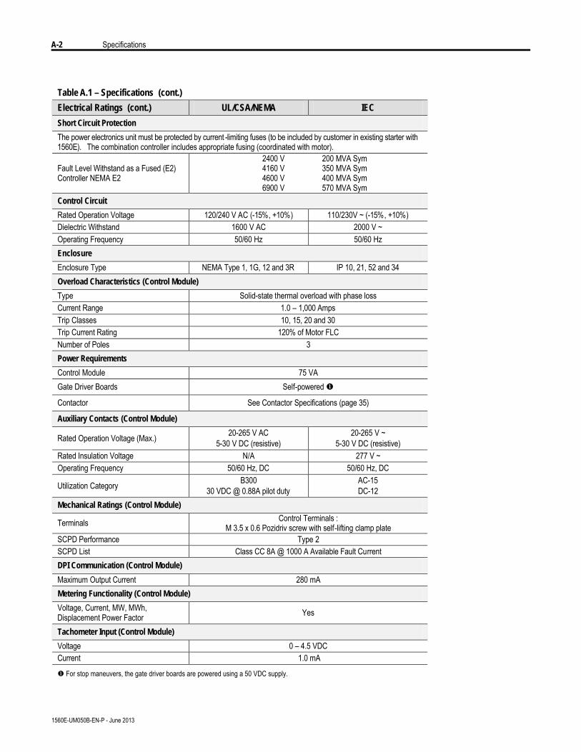
A-2 Specifications
1560E-UM050B-EN-P - June 2013
Table A.1 – Specifications (cont.)
Electrical Ratings (cont.) UL/CSA/NEMA IEC
Short Circuit Protection
The power electronics unit must be protected by current -limiting fuses (to be included by customer in existing starter with 1560E). The combination controller includes appropriate fusing (coordinated with motor).
Fault Level Withstand as a Fused (E2) Controller NEMA E2
2400 V 200 MVA Sym 4160 V 350 MVA Sym 4600 V 400 MVA Sym 6900 V 570 MVA Sym
Control Circuit
Rated Operation Voltage 120/240 V AC (-15%, +10%) 110/230V ~ (-15%, +10%) Dielectric Withstand 1600 V AC 2000 V ~ Operating Frequency 50/60 Hz 50/60 Hz Enclosure
Enclosure Type NEMA Type 1, 1G, 12 and 3R IP 10, 21, 52 and 34 Overload Characteristics (Control Module)
Type Solid-state thermal overload with phase loss Current Range 1.0 – 1,000 Amps Trip Classes 10, 15, 20 and 30 Trip Current Rating 120% of Motor FLC Number of Poles 3 Power Requirements
Control Module 75 VA Gate Driver Boards Self-powered u
Contactor See Contactor Specifications (page 35)
Auxiliary Contacts (Control Module)
Rated Operation Voltage (Max.) 20-265 V AC 5-30 V DC (resistive)
20-265 V ~ 5-30 V DC (resistive)
Rated Insulation Voltage N/A 277 V ~ Operating Frequency 50/60 Hz, DC 50/60 Hz, DC
Utilization Category B300 30 VDC @ 0.88A pilot duty
AC-15 DC-12
Mechanical Ratings (Control Module)
Terminals Control Terminals : M 3.5 x 0.6 Pozidriv screw with self-lifting clamp plate
SCPD Performance Type 2 SCPD List Class CC 8A @ 1000 A Available Fault Current DPI Communication (Control Module)
Maximum Output Current 280 mA Metering Functionality (Control Module)
Voltage, Current, MW, MWh, Displacement Power Factor Yes
Tachometer Input (Control Module)
Voltage 0 – 4.5 VDC Current 1.0 mA
u For stop maneuvers, the gate driver boards are powered using a 50 VDC supply.
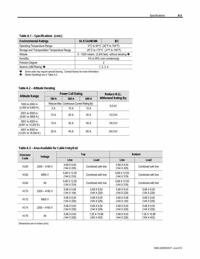
Specifications A-3
1560E-UM050B-EN-P - June 2013
Table A.1 – Specifications (cont.)
Environmental Ratings UL/CSA/NEMA IEC Operating Temperature Range 0°C to 40°C (32°F to 104°F) Storage and Transportation Temperature Range -20°C to +75°C (-4°F to 149°F) Altitude 0 - 1000 meters (3,300 feet) without derating v Humidity 5% to 95% (non condensing) Pollution Degree 2 Seismic (UBCRating) u 1, 2, 3, 4 u Some units may require special bracing. Contact factory for more information. v Starter Deratings are in Table A.2.
Table A.3 – Area Available for Cable Entry/Exit
Top Bottom Structure Code Voltage
Line Load Line Load
14.60 2300 – 4160 V 5.68 X 9.00 (144 X 229) Combined with line 5.68 X 9.00
(144 X 229) Combined with line
14.62 6900 V 5.68 X 12.55 (144 X 319) Combined with line 5.68 X 12.55
(144 X 319) Combined with line
14.64 All 5.68 X 12.55 (144 X 319) Combined with line 5.68 X 12.55
(144 X 319) Combined with line
14.70 2300 – 4160 V 5.68 X 5.68 (144 X 144)
5.68 X 9.00 (144 X 229)
5.68 X 9.00 (144 X 229)
5.68 X 9.00 (144 X 229)
14.72 6900 V 5.68 X 9.00 (144 X 229)
5.68 X 9.00 (144 X 229)
5.68 X 5.68 (144 X 144)
5.68 X 9.00 (144 X 229)
14.74 2300 – 4160 V 5.68 X 9.00 (144 X 229)
5.68 X 9.00 (144 X 229)
5.68 X 9.00 (144 X 229)
5.68 X 9.00 (144 X 229)
14.76 All 5.68 X 9.00 (144 X 229)
7.25 X 15.88 (184 X 403)
5.68 X 9.00 (144 X 229)
7.25 X 15.88 (184 X 403)
Dimensions are in inches (mm).
Table A.2 – Altitude Derating
Power Cell Rating Altitude Range
180 A 360 A 600 A Reduce B.I.L.
Withstand Rating By:
Reduce Max. Continuous Current Rating By: 1000 to 2000 m (3,300 to 6,600 ft.) 5 A 10 A 15 A
6.0 kV
2001 to 3000 m (6,601 to 9900 ft.) 10 A 20 A 30 A 12.0 kV
3001 to 4000 m (9,901 to 13,200 ft.) 15 A 30 A 45 A 18.0 kV
4001 to 5000 m (13,201 to 16,500 ft.) 20 A 40 A 60 A 24.0 kV
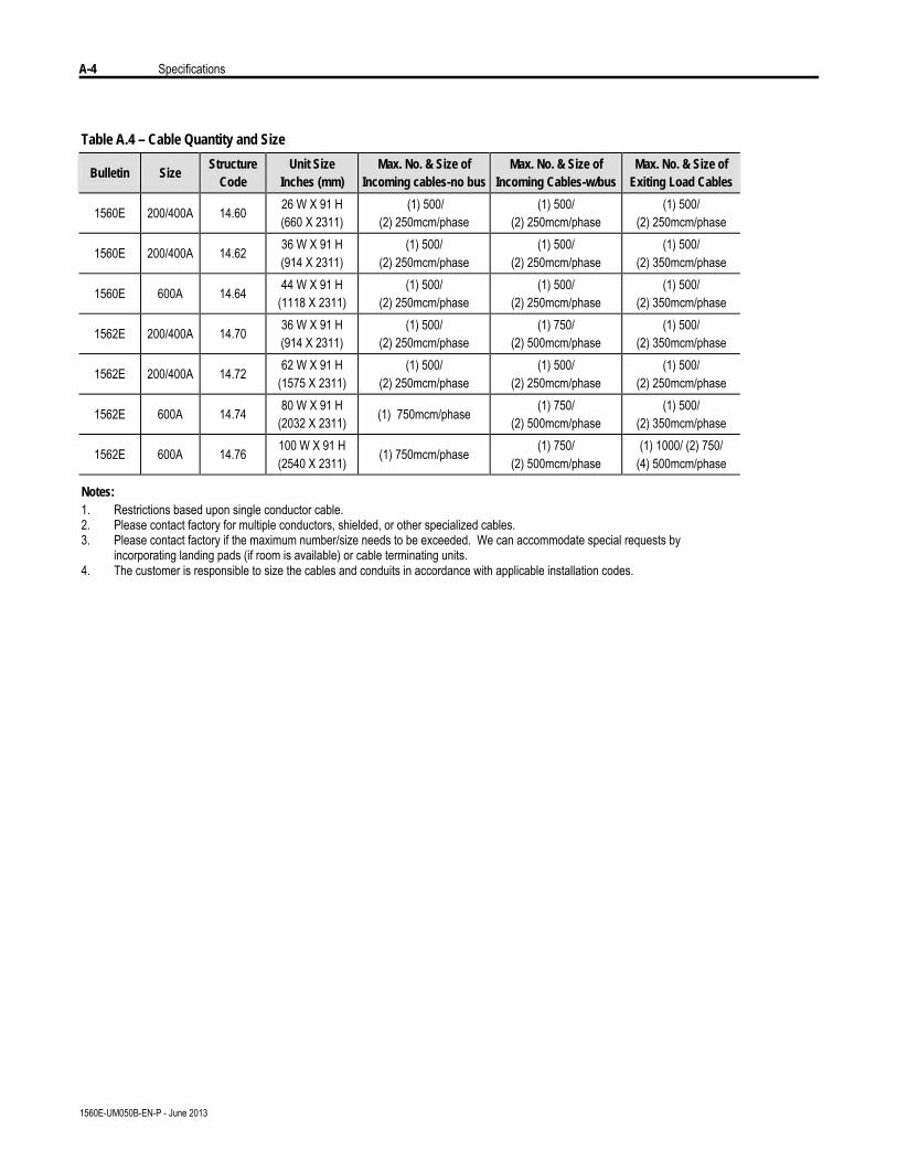
A-4 Specifications
1560E-UM050B-EN-P - June 2013
Table A.4 – Cable Quantity and Size
Bulletin Size Structure
Code Unit Size
Inches (mm) Max. No. & Size of
Incoming cables-no bus Max. No. & Size of
Incoming Cables-w/bus Max. No. & Size of
Exiting Load Cables
1560E 200/400A 14.60 26 W X 91 H (660 X 2311)
(1) 500/ (2) 250mcm/phase
(1) 500/ (2) 250mcm/phase
(1) 500/ (2) 250mcm/phase
1560E 200/400A 14.62 36 W X 91 H (914 X 2311)
(1) 500/ (2) 250mcm/phase
(1) 500/ (2) 250mcm/phase
(1) 500/ (2) 350mcm/phase
1560E 600A 14.64 44 W X 91 H (1118 X 2311)
(1) 500/ (2) 250mcm/phase
(1) 500/ (2) 250mcm/phase
(1) 500/ (2) 350mcm/phase
1562E 200/400A 14.70 36 W X 91 H (914 X 2311)
(1) 500/ (2) 250mcm/phase
(1) 750/ (2) 500mcm/phase
(1) 500/ (2) 350mcm/phase
1562E 200/400A 14.72 62 W X 91 H (1575 X 2311)
(1) 500/ (2) 250mcm/phase
(1) 500/ (2) 250mcm/phase
(1) 500/ (2) 250mcm/phase
1562E 600A 14.74 80 W X 91 H (2032 X 2311) (1) 750mcm/phase (1) 750/
(2) 500mcm/phase (1) 500/
(2) 350mcm/phase
1562E 600A 14.76 100 W X 91 H (2540 X 2311) (1) 750mcm/phase (1) 750/
(2) 500mcm/phase (1) 1000/ (2) 750/
(4) 500mcm/phase
Notes: 1. Restrictions based upon single conductor cable. 2. Please contact factory for multiple conductors, shielded, or other specialized cables. 3. Please contact factory if the maximum number/size needs to be exceeded. We can accommodate special requests by
incorporating landing pads (if room is available) or cable terminating units. 4. The customer is responsible to size the cables and conduits in accordance with applicable installation codes.
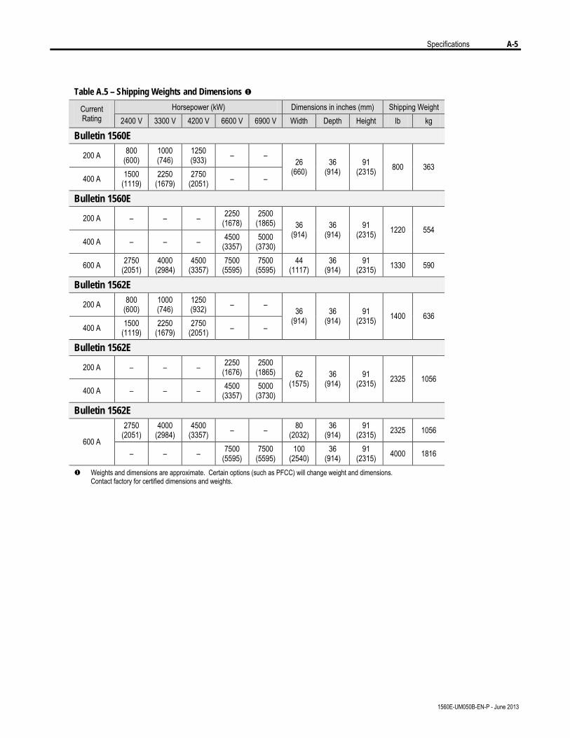
Specifications A-5
1560E-UM050B-EN-P - June 2013
Table A.5 – Shipping Weights and Dimensions u
Horsepower (kW) Dimensions in inches (mm) Shipping Weight Current Rating 2400 V 3300 V 4200 V 6600 V 6900 V Width Depth Height lb kg
Bulletin 1560E
200 A 800 (600)
1000 (746)
1250 (933) – –
400 A 1500 (1119)
2250 (1679)
2750 (2051) – –
26 (660)
36 (914)
91 (2315) 800 363
Bulletin 1560E
200 A – – – 2250 (1678)
2500 (1865)
400 A – – – 4500 (3357)
5000 (3730)
36 (914)
36 (914)
91 (2315) 1220 554
600 A 2750 (2051)
4000 (2984)
4500 (3357)
7500 (5595)
7500 (5595)
44 (1117)
36 (914)
91 (2315) 1330 590
Bulletin 1562E
200 A 800 (600)
1000 (746)
1250 (932) – –
400 A 1500 (1119)
2250 (1679)
2750 (2051) – –
36 (914)
36 (914)
91 (2315) 1400 636
Bulletin 1562E
200 A – – – 2250 (1676)
2500 (1865)
400 A – – – 4500 (3357)
5000 (3730)
62 (1575)
36 (914)
91 (2315) 2325 1056
Bulletin 1562E 2750
(2051) 4000
(2984) 4500
(3357) – – 80 (2032)
36 (914)
91 (2315) 2325 1056
600 A – – – 7500
(5595) 7500
(5595) 100
(2540) 36
(914) 91
(2315) 4000 1816
u Weights and dimensions are approximate. Certain options (such as PFCC) will change weight and dimensions. Contact factory for certified dimensions and weights.
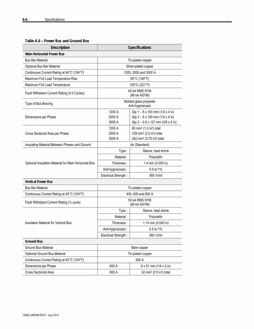
A-6 Specifications1
1560E-UM050B-EN-P - June 2013
Table A.6 – Power Bus and Ground Bus
Description Specifications
Main Horizontal Power Bus
Bus Bar Material Tin-plated copper Optional Bus Bar Material Silver-plated copper Continuous Current Rating at 40°C (104°F) 1200, 2000 and 3000 A Maximum Full Load Temperature Rise 65°C (149°F) Maximum Full Load Temperature 105°C (221°F)
Fault Withstand Current Rating (4.5 Cycles) 60 kA RMS SYM (96 kA ASYM)
Type of Bus Bracing Molded glass polyester Anti-hygroscopic
Dimensions per Phase 1200 A 2000 A 3000 A
Qty 1 – 6 x 100 mm (1/4 x 4 in) Qty 2 – 6 x 100 mm (1/4 x 4 in) Qty 2 – 9.5 x 127 mm (3/8 x 5 in)
Cross Sectional Area per Phase 1200 A 2000 A 3000 A
65 mm2 (1.0 in2) total 129 mm2 (2.0 in2) total 242 mm2 (3.75 in2) total
Insulating Material Between Phases and Ground Air (Standard) Type : Sleeve, heat shrink
Material : Polyolefin Thickness : 1.4 mm (0.055 in)
Anti-hygroscopic : 0.5 to 1% Optional Insulation Material for Main Horizontal Bus
Electrical Strength : 900 V/mil Vertical Power Bus
Bus Bar Material Tin-plated copper Continuous Current Rating at 40°C (104°F) 400, 600 and 800 A
Fault Withstand Current Rating (½ cycle) 50 kA RMS SYM (80 kA ASYM)
Type : Sleeve, heat shrink Material : Polyolefin
Thickness : 1.14 mm (0.045 in) Anti-hygroscopic : 0.5 to 1%
Insulation Material for Vertical Bus
Electrical Strength : 900 V/mil Ground Bus
Ground Bus Material Bare copper Optional Ground Bus Material Tin-plated copper Continuous Current Rating at 40°C (104°F) 600 A Dimensions per Phase 600 A 6 x 51 mm (1/4 x 2 in) Cross Sectional Area 600 A 32 mm2 (0.5 in2) total
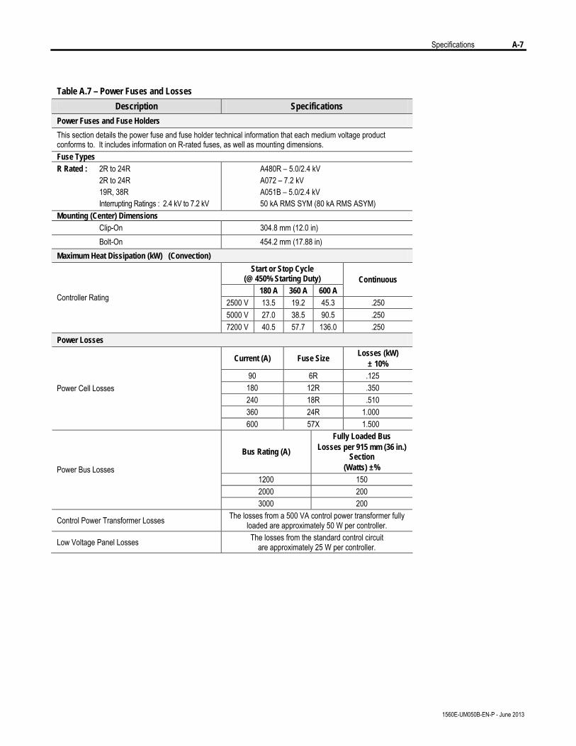
Specifications A-7
1560E-UM050B-EN-P - June 2013
Table A.7 – Power Fuses and Losses
Description Specifications
Power Fuses and Fuse Holders
This section details the power fuse and fuse holder technical information that each medium voltage product conforms to. It includes information on R-rated fuses, as well as mounting dimensions. Fuse Types R Rated : 2R to 24R 2R to 24R 19R, 38R Interrupting Ratings : 2.4 kV to 7.2 kV
A480R – 5.0/2.4 kV A072 – 7.2 kV A051B – 5.0/2.4 kV 50 kA RMS SYM (80 kA RMS ASYM)
Mounting (Center) Dimensions Clip-On 304.8 mm (12.0 in) Bolt-On 454.2 mm (17.88 in) Maximum Heat Dissipation (kW) (Convection)
Start or Stop Cycle (@ 450% Starting Duty)
180 A 360 A 600 A Continuous
2500 V 13.5 19.2 45.3 .250 5000 V 27.0 38.5 90.5 .250
Controller Rating
7200 V 40.5 57.7 136.0 .250 Power Losses
Current (A) Fuse Size Losses (kW)
± 10% 90 6R .125 180 12R .350 240 18R .510 360 24R 1.000
Power Cell Losses
600 57X 1.500
Bus Rating (A)
Fully Loaded Bus Losses per 915 mm (36 in.)
Section (Watts) ±%
1200 150 2000 200
Power Bus Losses
3000 200
Control Power Transformer Losses The losses from a 500 VA control power transformer fully loaded are approximately 50 W per controller.
Low Voltage Panel Losses The losses from the standard control circuit are approximately 25 W per controller.
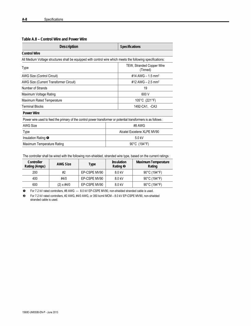
A-8 Specifications
1560E-UM050B-EN-P - June 2013
Table A.8 – Control Wire and Power Wire
Description Specifications
Control Wire
All Medium Voltage structures shall be equipped with control wire which meets the following specifications:
Type TEW, Stranded Copper Wire (Tinned)
AWG Size (Control Circuit) #14 AWG – 1.5 mm2 AWG Size (Current Transformer Circuit) #12 AWG – 2.5 mm2 Number of Strands 19 Maximum Voltage Rating 600 V Maximum Rated Temperature 105°C (221°F) Terminal Blocks 1492-CA1, -CA3
Power Wire
Power wire used to feed the primary of the control power transformer or potential transformers is as follows : AWG Size #8 AWG Type Alcatel Excelene XLPE MV90 Insulation Rating Ê 5.0 kV Maximum Temperature Rating 90°C (194°F) The controller shall be wired with the following non-shielded, stranded wire type, based on the current ratings :
Controller Rating (Amps) AWG Size Type Insulation
Rating Ë Maximum Temperature
Rating
200 #2 EP-CSPE MV90 8.0 kV 90°C (194°F) 400 #4/0 EP-CSPE MV90 8.0 kV 90°C (194°F) 600 (2) x #4/0 EP-CSPE MV90 8.0 kV 90°C (194°F)
Ê For 7.2 kV rated controllers, #8 AWG — 8.0 kV EP-CSPE MV90, non-shielded stranded cable is used. Ë For 7.2 kV rated controllers, #2 AWG, #4/0 AWG, or 350 kcmil MCM – 8.0 kV EP-CSPE MV90, non-shielded
stranded cable is used.
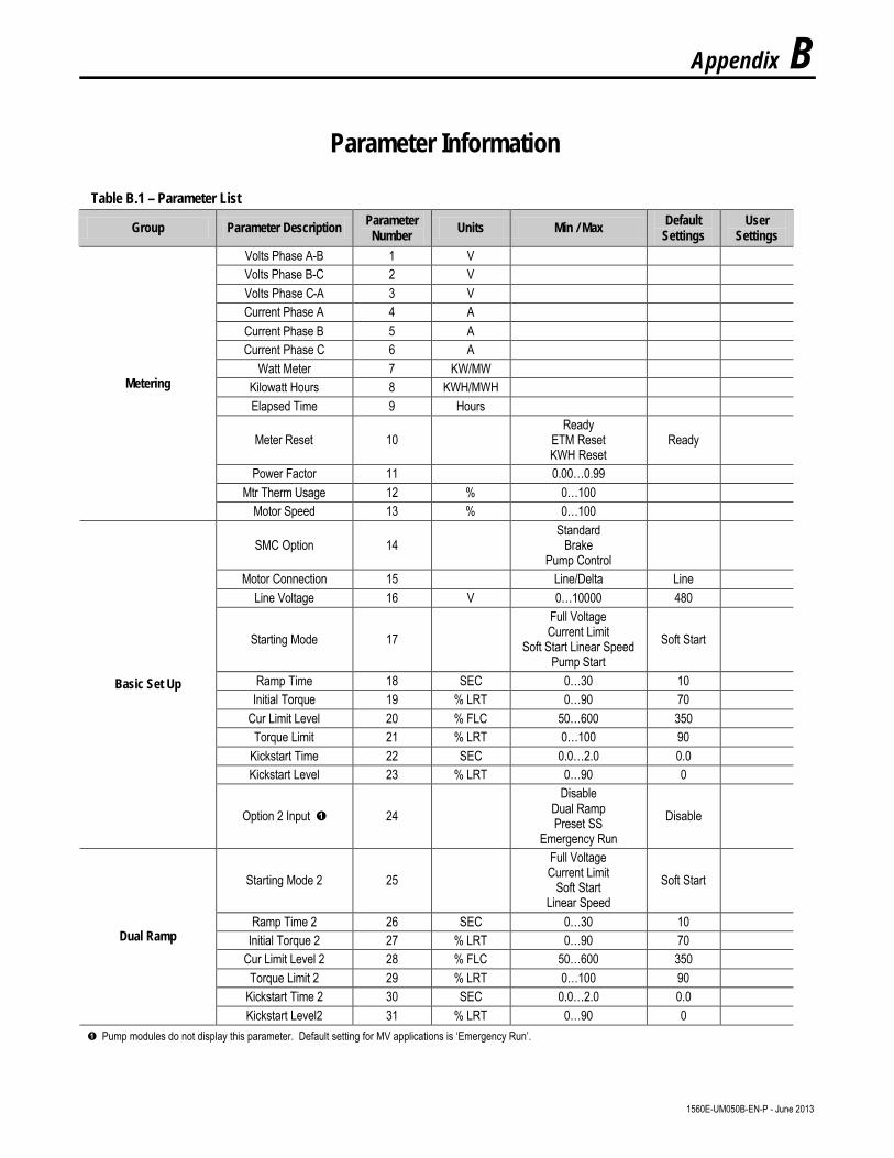
Appendix B
Parameter Information
1560E-UM050B-EN-P - June 2013
Table B.1 – Parameter List
Group Parameter Description Parameter Number Units Min / Max Default
Settings User
Settings Volts Phase A-B 1 V Volts Phase B-C 2 V Volts Phase C-A 3 V Current Phase A 4 A Current Phase B 5 A Current Phase C 6 A
Watt Meter 7 KW/MW Kilowatt Hours 8 KWH/MWH Elapsed Time 9 Hours
Meter Reset 10 Ready
ETM Reset KWH Reset
Ready
Power Factor 11 0.00…0.99 Mtr Therm Usage 12 % 0…100
Metering
Motor Speed 13 % 0…100
SMC Option 14 Standard
Brake Pump Control
Motor Connection 15 Line/Delta Line Line Voltage 16 V 0…10000 480
Starting Mode 17 Full Voltage Current Limit
Soft Start Linear Speed Pump Start
Soft Start
Ramp Time 18 SEC 0…30 10 Initial Torque 19 % LRT 0…90 70
Cur Limit Level 20 % FLC 50…600 350 Torque Limit 21 % LRT 0…100 90
Kickstart Time 22 SEC 0.0…2.0 0.0 Kickstart Level 23 % LRT 0…90 0
Basic Set Up
Option 2 Input Ê 24 Disable
Dual Ramp Preset SS
Emergency Run Disable
Starting Mode 2 25 Full Voltage Current Limit
Soft Start Linear Speed
Soft Start
Ramp Time 2 26 SEC 0…30 10 Initial Torque 2 27 % LRT 0…90 70
Cur Limit Level 2 28 % FLC 50…600 350 Torque Limit 2 29 % LRT 0…100 90
Kickstart Time 2 30 SEC 0.0…2.0 0.0
Dual Ramp
Kickstart Level2 31 % LRT 0…90 0 Ê Pump modules do not display this parameter. Default setting for MV applications is ‘Emergency Run’.
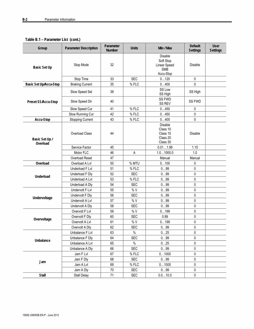
B-2 Parameter Information
1560E-UM050B-EN-P - June 2013
Table B.1 – Parameter List (cont.)
Group Parameter Description Parameter Number Units Min / Max Default
Settings User
Settings
Stop Mode 32
Disable Soft Stop
Linear Speed SMB
Accu-Stop
Disable Basic Set Up
Stop Time 33 SEC 0…120 0 Basic Set Up/Accu-Stop Braking Current 35 % FLC 0…400 0
Slow Speed Sel 39 SS Low SS High SS High
Slow Speed Dir 40 SS FWD SS REV SS FWD
Slow Speed Cur 41 % FLC 0…450 0
Preset SS/Accu-Stop
Slow Running Cur 42 % FLC 0…450 0 Accu-Stop Stopping Current 43 % FLC 0…400 0
Overload Class 44
Disable Class 10 Class 15 Class 20 Class 30
Disable
Service Factor 45 0.01…1.99 1.15 Motor FLC 46 A 1.0…1000.0 1.0
Basic Set Up / Overload
Overload Reset 47 Manual Manual Overload Overload A Lvl 50 % MTU 0…100 0
Underload F Lvl 51 % FLC 0…99 0 Underload F Dly 52 SEC 0…99 0 Underload A Lvl 53 % FLC 0…99 0
Underload
Underload A Dly 54 SEC 0…99 0 Undervolt F Lvl 55 % V 0…99 0 Undervolt F Dly 56 SEC 0…99 0 Undervolt A Lvl 57 % V 0…99 0
Undervoltage
Undervolt A Dly 58 SEC 0…99 0 Overvolt F Lvl 59 % V 0…199 0 Overvolt F Dly 60 SEC 0.99 0 Overvolt A Lvl 61 % V 0…199 0
Overvoltage
Overvolt A Dly 62 SEC 0…99 0 Unbalance F Lvl 63 % 0…25 0 Unbalance F Dly 64 SEC 0…99 0 Unbalance A Lvl 65 % 0…25 0
Unbalance
Unbalance A Dly 66 SEC 0…99 0 Jam F Lvl 67 % FLC 0…1000 0 Jam F Dly 68 SEC 0…99 0 Jam A Lvl 69 % FLC 0…1000 0
Jam
Jam A Dly 70 SEC 0…99 0 Stall Stall Delay 71 SEC 0.0…10.0 0
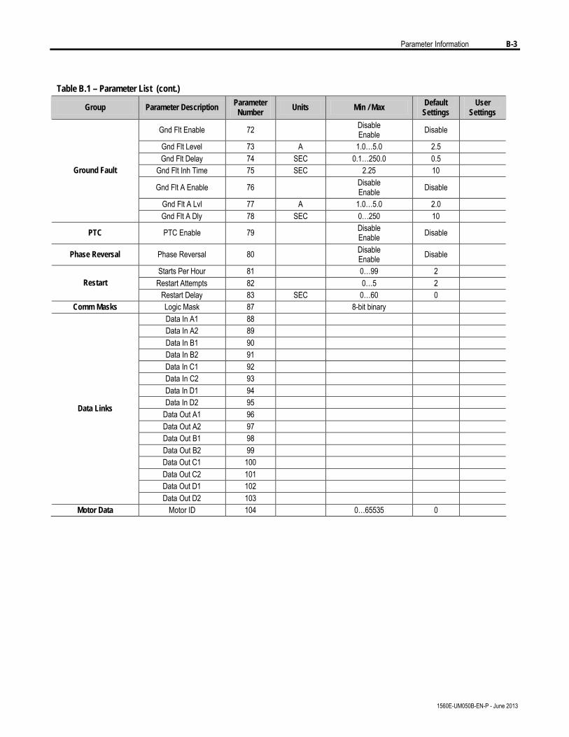
Parameter Information B-3
1560E-UM050B-EN-P - June 2013
Table B.1 – Parameter List (cont.)
Group Parameter Description Parameter Number Units Min / Max Default
Settings User
Settings
Gnd Flt Enable 72 Disable Enable Disable
Gnd Flt Level 73 A 1.0…5.0 2.5 Gnd Flt Delay 74 SEC 0.1…250.0 0.5
Gnd Flt Inh Time 75 SEC 2.25 10
Gnd Flt A Enable 76 Disable Enable Disable
Gnd Flt A Lvl 77 A 1.0…5.0 2.0
Ground Fault
Gnd Flt A Dly 78 SEC 0…250 10
PTC PTC Enable 79 Disable Enable Disable
Phase Reversal Phase Reversal 80 Disable Enable Disable
Starts Per Hour 81 0…99 2 Restart Attempts 82 0…5 2 Restart
Restart Delay 83 SEC 0…60 0 Comm Masks Logic Mask 87 8-bit binary
Data In A1 88 Data In A2 89 Data In B1 90 Data In B2 91 Data In C1 92 Data In C2 93 Data In D1 94 Data In D2 95
Data Out A1 96 Data Out A2 97 Data Out B1 98 Data Out B2 99 Data Out C1 100 Data Out C2 101 Data Out D1 102
Data Links
Data Out D2 103 Motor Data Motor ID 104 0…65535 0
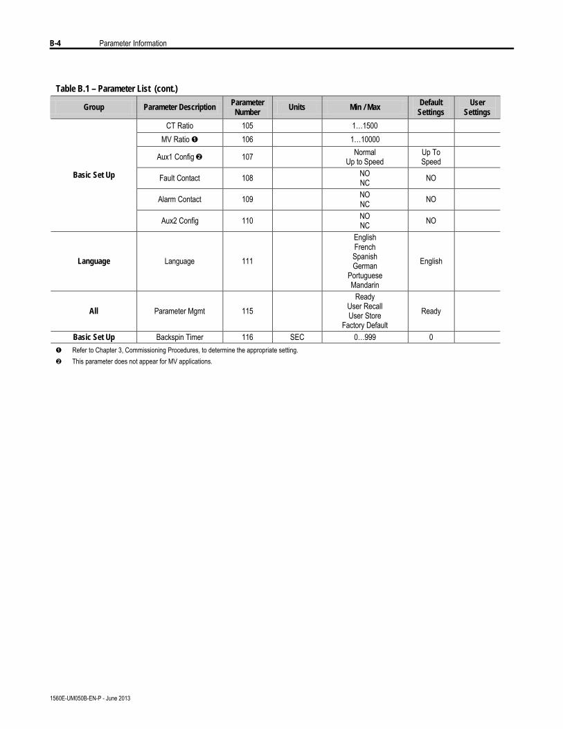
B-4 Parameter Information
1560E-UM050B-EN-P - June 2013
Table B.1 – Parameter List (cont.)
Group Parameter Description Parameter Number
Units Min / Max Default Settings
User Settings
CT Ratio 105 1…1500 MV Ratio Ê 106 1…10000
Aux1 Config Ë 107 Normal Up to Speed
Up To Speed
Fault Contact 108 NO NC NO
Alarm Contact 109 NO NC NO
Basic Set Up
Aux2 Config 110 NO NC NO
Language Language 111
English French Spanish German
Portuguese Mandarin
English
All Parameter Mgmt 115 Ready
User Recall User Store
Factory Default Ready
Basic Set Up Backspin Timer 116 SEC 0…999 0 Ê Refer to Chapter 3, Commissioning Procedures, to determine the appropriate setting. Ë This parameter does not appear for MV applications.
Appendix C
1560E and 1562E Relay Control
Functional Description The following functional descriptions and associated control circuits arefor units using electromechanical (relay) control.
Bulletin 1562E • Basic Control – Controlled Start only
When wired as shown in Figure C.1, the controller operates as follows:
Pressing the "Start" button initiates the start sequence. Relay "CR" closesand applies control power to terminal 17 of the SMC-Flex module. Theauxiliary contact #2 (set for "normal") closes, picking up "MC", whichcompletes the hold-in circuit on the start button, and closes the maincontactor.
The SMC-Flex module examines the line voltage, looks for faultconditions, checks phase rotation, calculates zero crossing information,and begins gating the SCRs to start the motor.
When the motor approaches rated speed, the SMC-Flex module closes the"AUX1" (up-to-speed) auxiliary contacts, closing relay "BC", which closesthe bypass contactor. The motor then runs at full line voltage.
When the "Stop" button is pressed, the "CR" relay opens terminal 17 onthe SMC-Flex module. The "AUX2" (Normal) contact opens, droppingout the main contactor, allowing the motor to stop. The "AUX1" contactalso opens, but "BC" is held closed for a short time by the control module.This holds the bypass contactor closed for about 10 seconds to protect thepower electronics from any voltage transients due to opening the motorcircuits.
1560E-UM050B-EN-P - June 2013
C-2 1560E and 1560E Relay Control
1560E-UM050B-EN-P - June 2013
Functional Description (cont.) Bulletin 1562E • Basic Control – With Controlled Stop
When wired as shown in Figure C.2, the controller operates in much thesame manner as in Figure C.1.
Terminal 16 on the SMC-Flex module now controls the start and stopmaneuvers. Terminal 16 must remain energized for the module to run.When the “Stop” button is pressed, and “CR” opens, the SMC-Flex modulewill initiate the option stop. An uncontrolled, or coast stop, is achieved byopening the connection to terminal 17. This contact should remain open toensure all hold-in contacts clear, to prevent a re-start.
If the motor has started, the unit is in the bypass mode, and a trip occurswithin the SMC-Flex module or from an external protection relay, Aux 2will open the line contactor immediately. "AUX1" will remain closed for10 seconds. A trip due to an overload or fault condition will result in a“coast” stop.
Bulletin 1562E • DPI Control – Controlled Start only
Refer to Figure C.3 and description on page 1-29.
1560E and 1560E Relay Control C-3
1560E-UM050B-EN-P - June 2013
Bulletin 1560E • Basic Control – Controlled Start Only
The Bulletin 1560E is intended for addition to an existing motor controller,which provides circuit isolation, motor switching, and overload andovercurrent protection. When wired as shown in Figure C.4, the controlleroperates as follows:
When a start is initiated in the existing motor controller and the contactor(or breaker) closes, a contact must be supplied to tell the 1560E to startalso. A "CR" contact will apply control voltage to terminal 17 of theSMC-Flex module.
When stopping the motor, the contactor in the existing controller will open,removing power from the motor, and then the “CR” relay. The bypasshold-in rung will keep the bypass contactor closed for a short time.
The “Fault” contact on the SMC-Flex module should be wired into theexisting controller to trip the main contactor (or breaker) in the event of afault condition sensed by the SMC-Flex module.
If possible, it is better to have the SMC-Flex module control the maincontactor directly. In this case, the control circuit would look like, andfunction like, the descriptions above for the Bulletin 1562E.
Bulletin 1560E • Basic control – With Controlled Stop
When wired as shown in Figure C.5, the controller operates much the sameas described above for the Standard module. The control signal usesterminal 16 instead of 17, and a “coast” stop can be achieved by openingthe connection to terminal 17.
It is more important in this configuration to integrate the control circuit ofthe 1560E with the existing controller, for better control of the Stop option.The “start signal” for this scheme cannot be a slave of the main contactor,since it must remain closed to accomplish the option stop maneuver. TheSMC-Flex module can be used to control the main contactor such that itwill close when a start is initiated, and remain closed until it has sensed themotor has stopped following an option stop maneuver.
Bulletin 1560E • DPI Control – Controlled Start only
Refer to Figure C.6 and description on page 1-31.
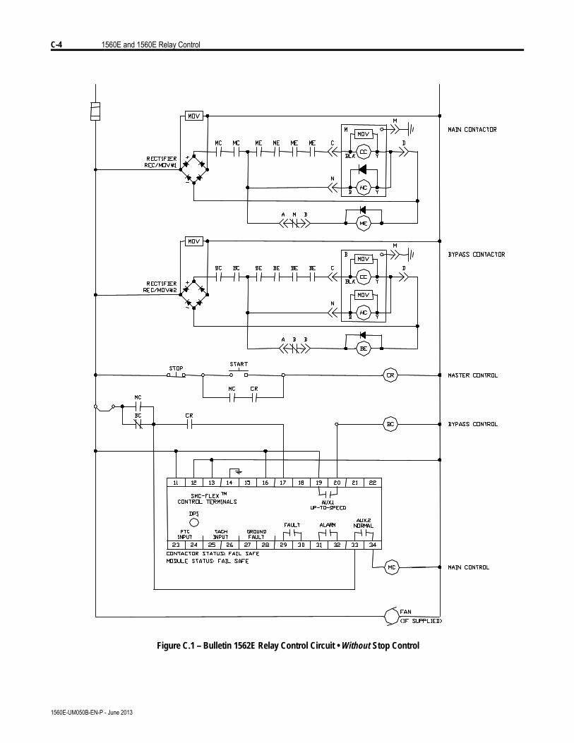
C-4 1560E and 1560E Relay Control
1560E-UM050B-EN-P - June 2013
Figure C.1 – Bulletin 1562E Relay Control Circuit • Without Stop Control

1560E and 1560E Relay Control C-5
1560E-UM050B-EN-P - June 2013
Figure C.2 – Bulletin 1562E Relay Control Circuit • With Stop Control
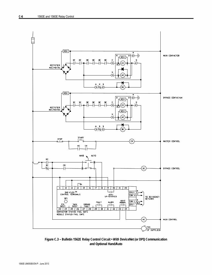
C-6 1560E and 1560E Relay Control
1560E-UM050B-EN-P - June 2013
Figure C.3 – Bulletin 1562E Relay Control Circuit • With DeviceNet (or DPI) Communicationand Optional Hand/Auto
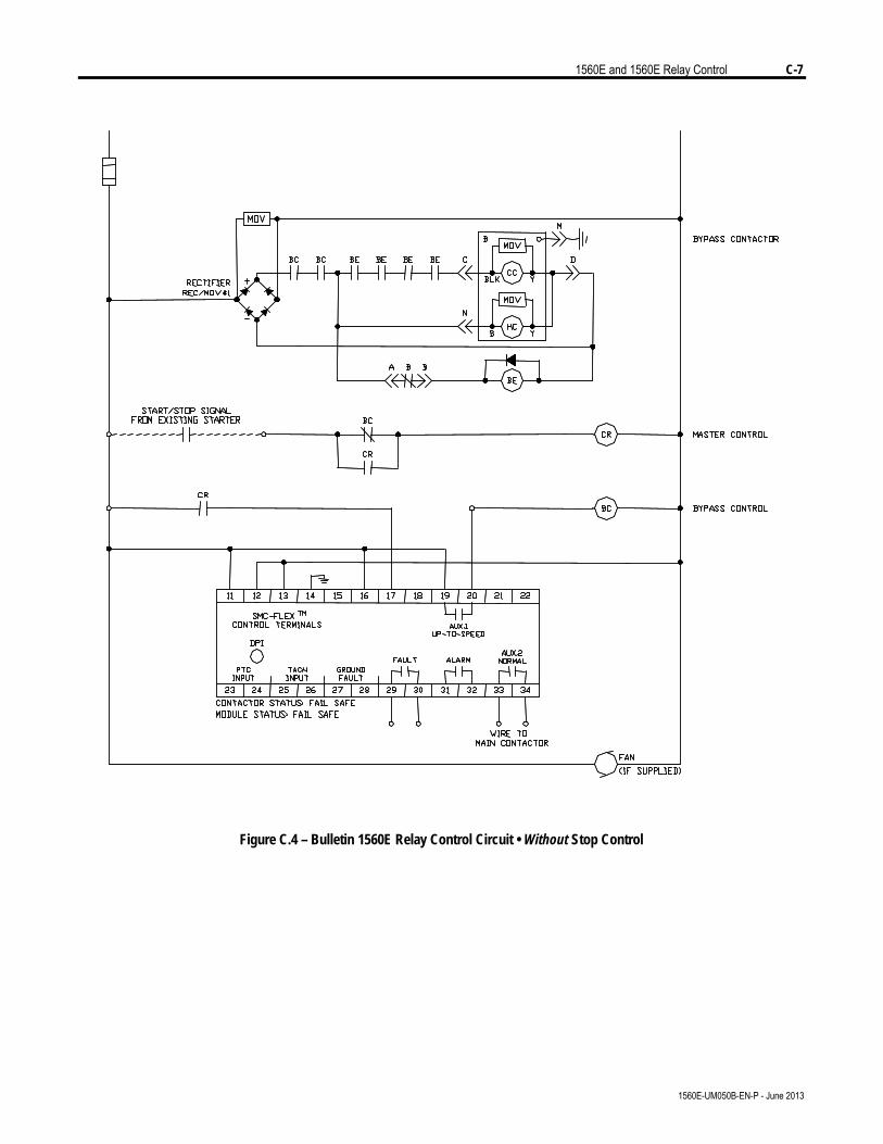
1560E and 1560E Relay Control C-7
1560E-UM050B-EN-P - June 2013
Figure C.4 – Bulletin 1560E Relay Control Circuit • Without Stop Control

C-8 1560E and 1560E Relay Control
1560E-UM050B-EN-P - June 2013
Figure C.5 – Bulletin 1560E Relay Control Circuit • With Stop Control
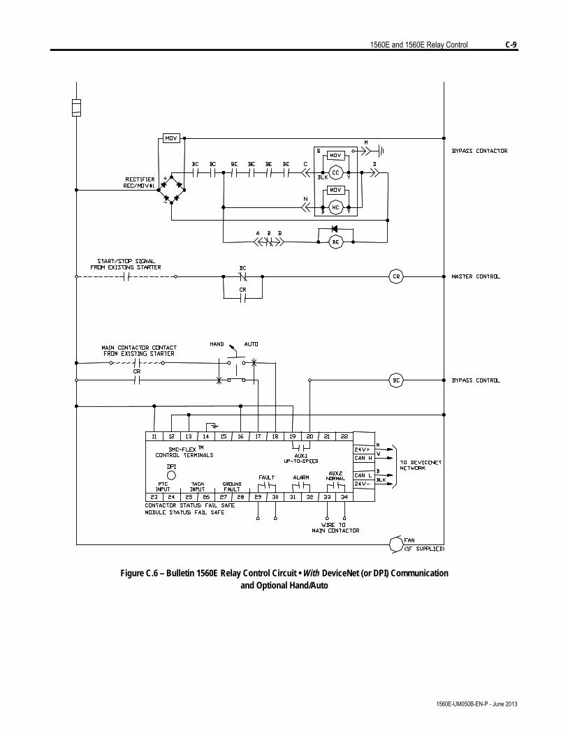
1560E and 1560E Relay Control C-9
1560E-UM050B-EN-P - June 2013
Figure C.6 – Bulletin 1560E Relay Control Circuit • With DeviceNet (or DPI) Communicationand Optional Hand/Auto

C-10 1560E and 1560E Relay Control11
1560E-UM050B-EN-P - June 2013

Appendix D
Spare Parts
1560E-UM050B-EN-P - June 2013
Table D.1 Bulletin 1503E • 1000-1500 Volt, 180/360 Amp, 6-device Ì
Qty per controller Description Part Number
180 A
6 Individual SCR, 5STP04D5200 (matching not required) Ê Ë 80156-815-61-R 360 A
6 Individual SCR, 5STP08G6500 (matching not required) Ê Ë 80156-894-71-R
Common Components Í 80165-898-52-R 3 SCR Gate Driver Board
(2 devices) Î 80165-898-55-R 1 IGDPS Board Î 80026-044-02-R 1 Voltage Sensing Module 81000-199-55-R 1 MV SMC Interface Circuit Board 80190-440-01-R 9 Snubber Resistor 80025-588-02-R
1000 V, 1.0 µF 80025-812-01-R 3 Snubber Capacitor (4.5 kV peak) 1300-1500V, 0.68 µF 80025-812-02-R
3 Sharing Resistor, 32.5 k, 225 W, Two 2.5 k Tap 80025-753-01-R 2.5 m 80025-549-03-R 9 Fiber-optic Cable 5.0 m 80025-549-01-R 120 V AC (North America) 80187-051-51-R 1 Test Power Supply Universal 80187-245-51-R
Ê If desired, a complete factory assembled SCR/heatsink assembly with snubber resistor and capacitor can be purchased rather than individual SCRs. See table below for part numbers :
Qty per controller Description Part Number 3 180 Amp, 1000 Volt Controller 80157-863-55 3 360 Amp, 1000 Volt Controller 80157-863-56 3 180 Amp, 1300V and 1500V Controller 80157-863-54 3 360 Amp, 1300V and 1500V Controller 80157-863-52
Ë Requires a thin film of electrical joint compound between base and mounting surface. Available with SCR replacement parts or separately as Part Number 80025-783-51. Ì Reference only. 1503E – For OEM products, refer to OEM-supplied documentation for specific spare parts list. 1560/1562E are Allen-Bradley manufactured starters. Refer to Service Manual for specific spare parts list.
Í Used when options 13XG (Stop Control) or 13XB (Pump Control) are not provided.
Î Used when options 13XG (Stop Control) or 13XB (Pump Control) are provided.
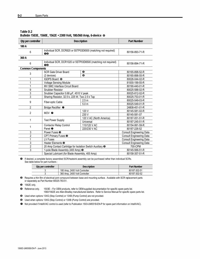
D-2 Spare Parts
1560E-UM050B-EN-P - June 2013
Table D.2 Bulletin 1503E, 1560E, 1562E • 2300 Volt, 180/360 Amp, 6-device Í
Qty per controller Description Part Number
180 A
6 Individual SCR, DCR820 or 5STP03D6500 (matching not required) ÊË 80156-893-71-R
360 A
6 Individual SCR, DCR1020 or 5STP03D6500 (matching not required) ÊË 80156-894-71-R
Common Components Î 80165-898-52-R 3 SCR Gate Driver Board
(2 devices) Ï 80165-898-55-R 1 IGDPS Board Ï 80026-044-02-R 1 Voltage Sensing Module 81000-199-55-R 1 MV SMC Interface Circuit Board 80190-440-01-R 9 Snubber Resistor 80025-588-02-R 3 Snubber Capacitor 0.68 µF, 4510 V peak 80025-812-02-R 3 Sharing Resistor, 32.5 k, 225 W, Two 2.5 k Tap 80025-753-01-R
2.5 m 80025-549-03-R 9 Fiber-optic Cable 5.0 m 80025-549-01-R 2 Bridge Rectifier 24808-451-01-R
120 V 80145-581-02-R 2 MOV 230 V 80145-581-07 120 V AC (North America) 80187-051-51-R 1 Test Power Supply Universal 80187-245-51-R 110/120 V AC 80154-991-59-R 1 Contactor Relay Control
Panel 220/230 V AC 80187-226-52 3 Power Fuses Ì Consult Engineering Data 2 CPT Primary Fuses Ì Consult Engineering Data
1 LV Fuses Consult Engineering Data 3 Heater Elements Ì Consult Engineering Data 2 20 Amp Contact Cartridge for Isolation Switch Auxiliary Ì 700-CPM 3 1-pole Blade Assembly (400 Amp) Ì 80145-566-51-R
Special Lubricant (for Blade Assembly, 400 Amp) 80158-357-51-R
Ê If desired, a complete factory assembled SCR/heatsink assembly can be purchased rather than individual SCRs. See table below for part numbers :
Qty per controller Description Part Number 3 180 Amp, 2400 Volt Controller 80187-302-51 3 360 Amp, 2400 Volt Controller 80187-302-52
Ë Requires a thin film of electrical joint compound between base and mounting surface. Available with SCR replacement parts or separately as Part Number 80025-783-51. Ì 1562E only. Í Reference only. 1503E – For OEM products, refer to OEM-supplied documentation for specific spare parts list. 1560/1562E are Allen-Bradley manufactured starters. Refer to Service Manual for specific spare parts list. Î Used when options 13XG (Stop Contrtol) or 13XB (Pump Control) are not provided. Ï Used when options 13XG (Stop Control) or 13XB (Pump Control) are provided. Not provided if IntelliVAC control is used (refer to Publication 1503-UM051B-EN-P for spare part information on IntelliVAC).

Spare Parts D-3
1560E-UM050B-EN-P - June 2013
Table D.3 Bulletin 1503E, 1560E, 1562E • 2300 Volt, 600 Amp, 6-Device Ë
Qty per controller Description Part Number
3 Heatsink Assembly 600A with Thermistor 80187-326-51-R
Note : Due to stringent torquing specifications in this application, it is MANDATORY that the entire heatsink assembly be replaced. Contact the Rockwell Automation factory.
Ì 80165-898-52-R 3 SCR Gate Driver Board (2 devices) Í 80165-898-55-R
1 IGDPS Board Í 80026-044-02-R 1 Voltage Sensing Module 81000-199-55-R 1 MV SMC Interface Circuit Board 80190-440-01-R 6 Snubber Resistor 80025-642-04-R 3 Snubber Capacitor 1.0 µF 80025-812-01-R 3 Sharing Resistor 32.5K, 225 W 80025-753-01-R
2.5 m 80025-549-03-R 9 Fiber-optic Cable 5.0 m 80025-549-01-R 2 Bridge Rectifier y 24808-451-01-R
120 V 80145-581-02-R 2 MOV y 230 V 80145-581-07 120V AC (North America) 80187-051-51-R 1 Test Power Supply Universal 80187-245-51-R 110/120 V AC 80154-991-59-R 1 Contactor Relay Control
Panel y 220/230 V AC 80187-226-54 3 Power Fuses Ê Consult Engineering Data 2 CPT Primary Fuses u Consult Engineering Data
1 LV Fuses Consult Engineering Data 3 Heater Elements u Consult Engineering Data 2 20 Amp Contact Cartridge for Isolation Switch Auxiliary u 700-CPM
600 A 80157-710-51-R 3 Isolating Switch Blade Assembly
1-pole (fixed blade assembly) 800 A Consult the Rockwell Automation factory
600 A 80157-709-51-R 3 Isolating Switch Blade Assembly
1-pole (moving blade assembly) 800 A Consult the Rockwell Automation factory
Special Lubricant (for Blade Assembly) 80158-357-51 Ê 1562E only. Ë Reference only. 1503E – For OEM products, refer to OEM-supplied documentation for specific spare parts list. 1560/1562E are Allen-Bradley manufactured starters. Refer to Service Manual for specific spare parts list. Ì Used when options 13XG (Stop Control) or 13XB (Pump Control) are not provided. Í Used when options 13XG (Stop Control) or 13XB (Pump Control) are provided. y Not provided if IntelliVAC control is used (refer to Publication 1503-UM051B-EN-P for spare part information for IntelliVAC).

D-4 Spare Parts
1560E-UM050B-EN-P - June 2013
Table D.4 Bulletin 1503E, 1560E, 1562E • 3300 and 4160 Volt, 180/360 Amp, 12-device Í
Qty per controller Description Part Number
180 A 6 SCR, DCR820 or 5STP03D6500 (matched set of 2) ÊË 80156-893-72-R
360 A 6 SCR, DCR1020 or 5STP08G6500 (matched set of 2) ÊË 80156-894-72-R
Common Components Î 80165-858-52-R 3 SCR Gate Driver Board
(4 devices) Ï 80165-858-55-R 2 IGDPS Board Ï 80026-044-02-R 1 Voltage Sensing Module 81000-199-55-R 1 MV SMC Interface Circuit Board 80190-440-01-R 6 Snubber Resistor 80025-588-02-R 6 Snubber Capacitor 0.68 µF, 4510 V peak 80025-812-02-R 6 Sharing Resistor, 32.5 k, 225 W, Two 2.5 k Tap 80025-753-01-R
2.5 m 80025-549-03-R 15 Fiber-optic Cable 5.0 m 80025-549-01-R 2 Bridge Rectifier 24808-451-01-R
120 V 80145-581-02-R 2 MOV 230 V 80145-581-07 120 V (North America) 80187-051-51-R 1 Test Power Supply Universal 80187-245-51-R 110/120 V AC 80154-991-59-R 1 Contactor Relay Control
Panel 220/230 V AC 80187-226-52 3 Power Fuses Ì Consult Engineering Data 2 CPT Primary Fuses Ì Consult Engineering Data
2 LV Fuses Consult Engineering Data 3 Heater Elements Ì Consult Engineering Data 2 20 Amp Contact Cartridge for Isolation Switch Auxiliary Ì 700-CPM 3 1-pole Blade Assembly (400 Amp) Ì 80145-566-51-R Special Lubricant (for Blade Assembly, 400 Amp) 80158-357-51-R
u If desired, a complete factory assembled SCR/heatsink assembly can be purchased rather than individual SCRs.
See table below for part numbers :
Qty per controller Description Part Number 3 180 Amp, 3300/4160 Volt Controller 80187-305-51 3 360 Amp, 3300/4160 Volt Controller 80187-305-52 v Requires a thin film of electrical joint compound between base and mounting surface. Available with SCR replacement parts
or separately as Part Number 80025-783-51. w 1562E only. Í Reference only. 1503E – For OEM products, refer to OEM-supplied documentation for specific spare parts list. 1560/1562E are Allen-Bradley manufactured starters. Refer to Service Manual for specific spare parts list. Î Used when options 13XG (Stop Control) or 13XB (Pump Control) are not provided. Ï Used when options 13XG (Stop Control) or 13XB (Pump Control) are provided. Ð Not provided if IntelliVAC control is used (refer to Publication 1503-UM051B-EN-P for spare part information on IntelliVAC).

Spare Parts D-5
1560E-UM050B-EN-P - June 2013
Table D.5 Bulletin 1503E, 1560E, 1562E • 3300 and 4160 Volt, 600 Amp, 12-device Ë
Qty per controller Description Part Number
3 Heatsink Assembly 600A with Thermistor 80187-309-51-R
Note : Due to stringent torquing specifications in this application, it is MANDATORY that the entire heatsink assembly be replaced. Contact the Rockwell Automation factory.
Ì 80165-858-52-R 3 SCR Gate Driver Board (4 devices) Í 80165-858-55-R
2 IGDPS Board Í 80026-044-02-R 1 Voltage Sensing Module 81000-199-55-R 1 MV SMC Interface Circuit Board 80190-440-01-R 12 Snubber Resistor 80025-642-04-R 6 Snubber Capacitor 1.0 µF 80025-812-01-R 6 Sharing Resistor 32.5K, 225W 80025-753-01-R 15 2.5 m 80025-549-03-R 15 Fiber-optic Cable 5.0 m 80025-549-01-R 2 Bridge Rectifier Î 24808-451-01-R
120 V 80145-581-02-R 2 MOV 120V Î 230 V 80145-581-07 120V AC (North America) 80187-051-51-R 1 Test Power Supply Universal 80187-245-51-R
1 110/120 V AC 80154-991-59-R 1
Contactor Relay Control Panel Î 220/230 V AC 80187-226-54
3 Power Fuses u Consult Engineering Data 2 CPT Primary Fuses u Consult Engineering Data
1 LV Fuses Consult Engineering Data 3 Heater Elements u Consult Engineering Data 2 20 Amp Contact Cartridge for Isolation Switch Auxiliary u 700-CPM
600 A 80157-709-51-R 3 Isolating Switch Blade Assembly
1-pole (moving blade assembly) 800 A Consult the Rockwell Automation factory
600 A 80157-710-51-R 3 Isolating Switch Blade Assembly
1-pole (fixed blade assembly) 800 A Consult the Rockwell Automation factory
Special Lubricant (for Blade Assembly) 80158-357-51-R u 1562E only. Ë Reference only. 1503E – For OEM products, refer to OEM-supplied documentation for specific spare parts list. 1560/1562E are Allen-Bradley manufactured starters. Refer to Service Manual for specific spare parts list. Ì Used when options 13XG (Stop Control) or 13XB (Pump Control) are not provided. Í Used when options 13XG (Stop Control) or 13XB (Pump Control) are provided. Î Not provided if IntelliVAC control is used (refer to Publication 1503-UM051B-EN-P for spare part information on
IntelliVAC).
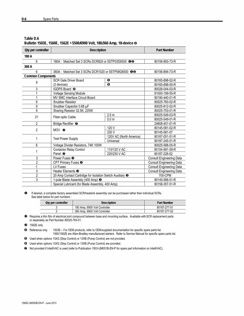
D-6 Spare Parts
1560E-UM050B-EN-P - June 2013
Table D.6 Bulletin 1503E, 1560E, 1562E • 5500/6900 Volt, 180/360 Amp, 18-device Í
Qty per controller Description Part Number
180 A 6 180A : Matched Set 3 SCRs DCR820 or 5STP03D6500 uË 80156-893-73-R
360 A 6 360A : Matched Set 3 SCRs DCR1020 or 5STP08G6500 uË 80156-894-73-R
Common Components Î 80165-898-52-R 9 SCR Gate Driver Board
(2 devices) Ï 80165-898-55-R 3 IGDPS Board Ï 80026-044-03-R 1 Voltage Sensing Module 81000-199-55-R 1 MV SMC Interface Circuit Board 80190-440-01-R 9 Snubber Resistor 80025-760-02-R 9 Snubber Capacitor 0.68 µF 80025-812-02-R 9 Sharing Resistor 32.5K, 225W 80025-753-01-R
2.5 m 80025-549-03-R 21 Fiber-optic Cable 5.0 m 80025-549-01-R 2 Bridge Rectifier Ð 24808-451-01-R
120 V 80145-581-02-R 2 MOV Ð 230 V 80145-581-07 120V AC (North America) 80187-051-51-R 1 Test Power Supply Universal 80187-245-51-R
6 Voltage Divider Resistors, 74K 100W 80025-588-05-R 110/120 V AC 80154-991-59-R 1 Contactor Relay Control
Panel Ð 220/230 V AC 80187-226-52 3 Power Fuses w Consult Engineering Data 2 CPT Primary Fuses w Consult Engineering Data
1 LV Fuses Consult Engineering Data 3 Heater Elements w Consult Engineering Data 2 20 Amp Contact Cartridge for Isolation Switch Auxiliary w 700-CPM 3 1-pole Blade Assembly (400 Amp) w 80145-566-51-R
Special Lubricant (for Blade Assembly, 400 Amp) 80158-357-51-R u If desired, a complete factory assembled SCR/heatsink assembly can be purchased rather than individual SCRs.
See table below for part numbers : Qty per controller Description Part Number 3 180 Amp, 6900 Volt Controller 80187-277-51 3 360 Amp, 6900 Volt Controller 80187-277-52
v Requires a thin film of electrical joint compound between base and mounting surface. Available with SCR replacement parts or separately as Part Number 80025-783-51. w 1562E only. Í Reference only. 1503E – For OEM products, refer to OEM-supplied documentation for specific spare parts list. 1560/1562E are Allen-Bradley manufactured starters. Refer to Service Manual for specific spare parts list. Î Used when options 13XG (Stop Control) or 13XB (Pump Control) are not provided. Ï Used when options 13XG (Stop Control) or 13XB (Pump Control) are provided. Ð Not provided if IntelliVAC is used (refer to Publication 1503-UM051B-EN-P for spare part information on IntelliVAC).
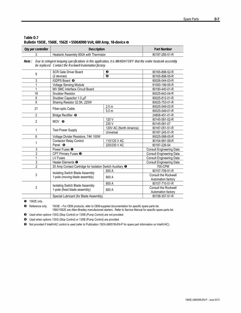
Spare Parts D-7
1560E-UM050B-EN-P - June 2013
Table D.7 Bulletin 1503E, 1560E, 1562E • 5500/6900 Volt, 600 Amp, 18-device Ë
Qty per controller Description Part Number
3 Heatsink Assembly 600A with Thermistor 80187-285-51-R
Note : Due to stringent torquing specifications in this application, it is MANDATORY that the entire heatsink assembly be replaced. Contact the Rockwell Automation factory.
Ì 80165-898-52-R 9 SCR Gate Driver Board (2 devices) Í 80165-898-55-R
3 IGDPS Board Í 80026-044-03-R 1 Voltage Sensing Module 81000-199-55-R 1 MV SMC Interface Circuit Board 80190-440-01-R 18 Snubber Resistor 80025-642-04-R 9 Snubber Capacitor 1.0 µF 80025-812-01-R 9 Sharing Resistor 32.5K, 225W 80025-753-01-R
2.5 m 80025-549-03-R 21 Fiber-optic Cable 5.0 m 80025-549-01-R 2 Bridge Rectifier Î 24808-451-01-R
120 V 80145-581-02-R 2 MOV Î 230 V 80145-581-07 120V AC (North America) 80187-051-51-R 1 Test Power Supply Universal 80187-245-51-R
6 Voltage Divider Resistors, 74K 100W 80025-588-05-R 110/120 V AC 80154-991-59-R 1 Contactor Relay Control
Panel Î 220/230 V AC 80187-226-54 3 Power Fuses u Consult Engineering Data 2 CPT Primary Fuses u Consult Engineering Data
1 LV Fuses Consult Engineering Data 3 Heater Elements u Consult Engineering Data 2 20 Amp Contact Cartridge for Isolation Switch Auxiliary u 700-CPM
600 A 80157-709-51-R 3 Isolating Switch Blade Assembly
1-pole (moving blade assembly) 800 A Consult the Rockwell Automation factory
600 A 80157-710-51-R 3 Isolating Switch Blade Assembly
1-pole (fixed blade assembly) 800 A Consult the Rockwell Automation factory
Special Lubricant (for Blade Assembly) 80158-357-51-R u 1562E only. Ë Reference only. 1503E – For OEM products, refer to OEM-supplied documentation for specific spare parts list. 1560/1562E are Allen-Bradley manufactured starters. Refer to Service Manual for specific spare parts list. Ì Used when options 13XG (Stop Control) or 13XB (Pump Control) are not provided. Í Used when options 13XG (Stop Control) or 13XB (Pump Control) are provided. Î Not provided if IntelliVAC control is used (refer to Publication 1503-UM051B-EN-P for spare part information on IntelliVAC).
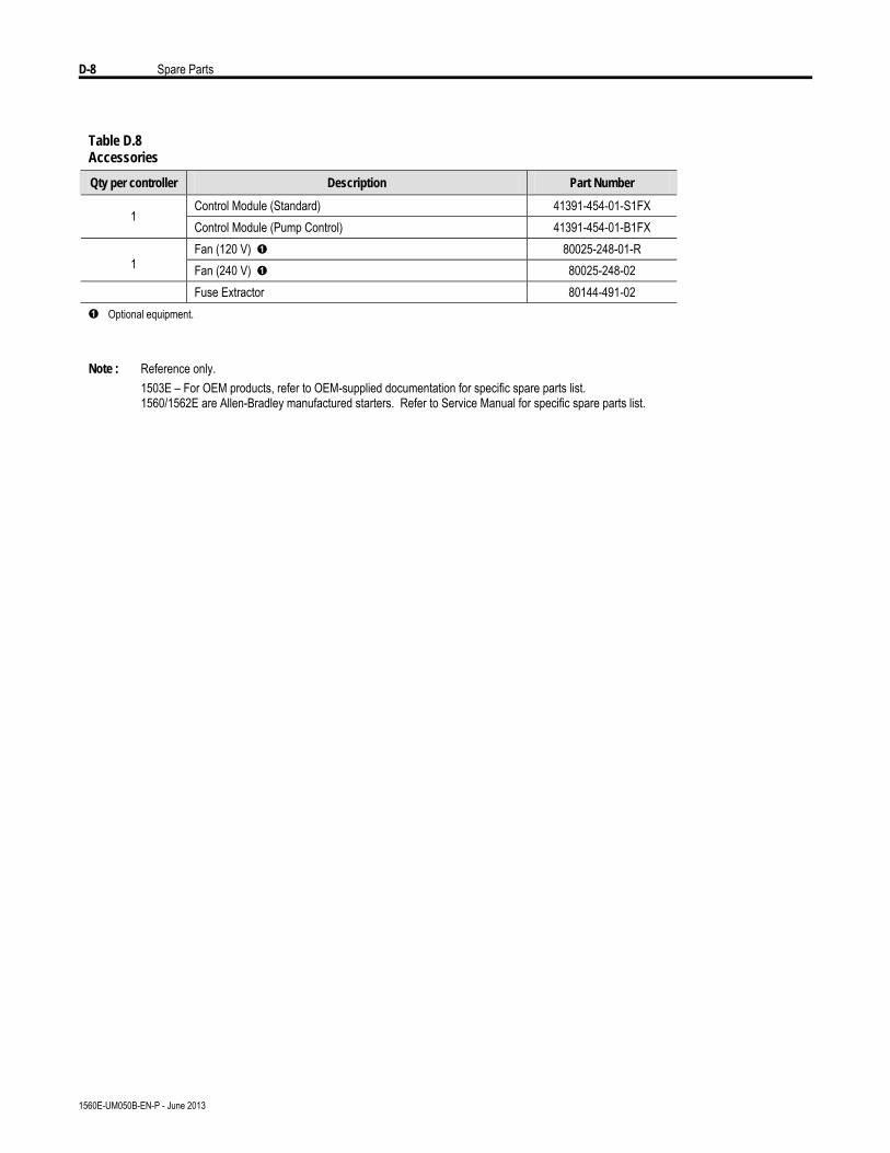
D-8 Spare Parts
1560E-UM050B-EN-P - June 2013
Table D.8 Accessories
Qty per controller Description Part Number
Control Module (Standard) 41391-454-01-S1FX 1
Control Module (Pump Control) 41391-454-01-B1FX Fan (120 V) Ê 80025-248-01-R
1 Fan (240 V) Ê 80025-248-02 Fuse Extractor 80144-491-02
Ê Optional equipment. Note : Reference only. 1503E – For OEM products, refer to OEM-supplied documentation for specific spare parts list. 1560/1562E are Allen-Bradley manufactured starters. Refer to Service Manual for specific spare parts list.
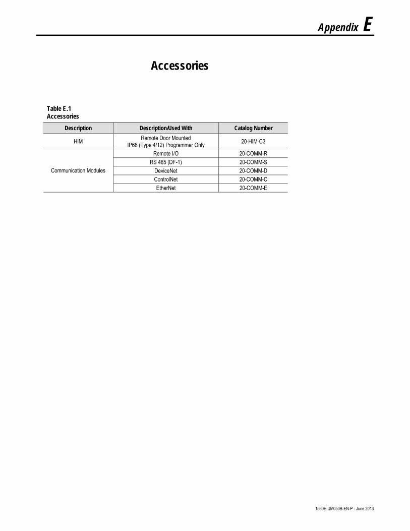
Appendix E
Accessories
1560E-UM050B-EN-P - June 2013
Table E.1 Accessories
Description Description/Used With Catalog Number
HIM Remote Door Mounted IP66 (Type 4/12) Programmer Only 20-HIM-C3
Remote I/O 20-COMM-R RS 485 (DF-1) 20-COMM-S
DeviceNet 20-COMM-D ControlNet 20-COMM-C
Communication Modules
EtherNet 20-COMM-E

E-2 Accessories
1560E-UM050B-EN-P - June 2013


Medium Voltage Business, 135 Dundas Street, Cambridge, ON N1R 5X1 Canada, Tel: (1) 519 623-1810, Fax: (1) 519 623-8930 Web Site: www.ab.com/mvb
Publication 1560E-UM050B-EN-P – June 2013 © 2013 Rockwell International Corporation. All rights reserved. Printed in Canada.Supersedes Publication 1560E-UM050A-EN-P – August 2004