Embed Size (px)
Citation preview

Selection Guide
SMC™-3 and SMC Flex Smart Motor Controllers

2

Bulletin 150
Reduced Voltage Starters
3www.ab.com/catalogs
Publication 150-SG009F-EN-P
Product Overview/Modes of Operation
Bulletin 150 — Solid-State Reduced Voltage StartersThe Allen-Bradley SMC™ Smart Motor Controller product line offers a broad range of products for starting and stopping standard 3-phasesquirrel-cage induction motors and wye-delta motors.
Features
SMC™ Flex SMC™-3
200…690V1…1250 A
200…600V1…480 A
Soft Start S S
Kickstart S S
Current Limit S S
Dual Ramp Start S —
Full Voltage S —
Energy Saver — —
Soft Stop S S
Pump Control O —
Preset Slow Speed S —
Linear Acceleration/Deceleration S —
Torque Control — —
SMB™ Smart Motor Braking O —
Accu-Stop™ O —
Slow Speed with Braking O —
Integrated Bypass Contactor S S
Integrated Motor Overload Protection S S
Single-phase Operation — —
DPI Communication S —
Metering S —
Real Time Clock — —
Motor Winding Heater Function ‡ —
Diagnostic Faults and Alarms S —
Motor and Starter — —
Individual Bit Enable of Faults andAlarms — —
Automatic Tuning of MotorParameters — —
ParameterConfiguration/Programming S —
Human Interface Module (HIM) O —
Parameter Configruation Module — —
Configuration Software: DrivesExplorer and Drives Executive O —
Digital I/O Expansion Module§♣ — —
Ground Fault/CT/PTC Module§ — —
Network Communications O —
Inside Delta Connection S S
Standards Compliance:CE Marked per Low Voltage Directive73/23/EEC, 93/68/EECCSA Certified (File No. LR 1234)UL Listed (File No. E96956)
S S
Product Selection Page 6 Page 30
S = Standard FeatureO = Optional Feature�Starter does not include a configuration device as standard.‡ Option using a Bulletin 1410 motor winding heater.§ With removable terminal block.♣ Starter ships with 2 DC inputs and 2 relay outputs as standard.♠ The starter is fully solid-state (no integral bypass). An external bypass contactor can be added as an option.& Note: Information for this product line is available on the Industrial Controls catalog web site: www.ab.com/catalogs.Δ Note: Information for this product line is available in publication 150-SG010* or on the Industrial Controls catalog web site: www.ab.com/catalogs.

Bulletin 150
Reduced Voltage Starters
4www.ab.com/catalogs
Publication 150-SG009F-EN-P
Modes of OperationThe SMC controllers provide the following modes of operation:Soft Start
This method covers the most general applications. The motor isgiven an initial torque setting, which is user adjustable. From theinitial torque level, the output voltage to the motor is steplesslyincreased during the acceleration ramp time, which is useradjustable.
Perc
ent V
olta
ge
100%
InitialTorque
Time in SecondsStart Run
Ramp Time
Selectable Kickstart
The kickstart feature provides a boost at startup to break awayloads that may require a pulse of high torque to get started. It isintended to provide a current pulse, for a selected period of time.
Perc
ent V
olta
ge 100%
Initial Torque
Kickstart
Time [s]Start Run
Current Limit Start
This method provides current limit start and is used when it isnecessary to limit the maximum starting current. The starting currentis user adjustable. The current limit stating time is user adjustable.
Perc
ent F
ull L
oad
Cur
rent
600%
50%
StartTime [s]
Dual Ramp Start
This starting method is useful on applications with varying loads,starting torque, and start time requirements. Dual Ramp Start offersthe user the ability to select between two separate start profiles withseparately adjustable ramp times and initial torque settings.
Initial Torque
#2
Initial Torque
#1
Ramp #1
Ramp #2
Time [s]
Perc
ent V
olta
ge
100%
Start #1Start #2
Run #1Run #2
Full Voltage Start
This method is used in applications requiring across-the-linestarting. The SMC controller performs like a solid-state contactor.Full inrush current and locked-rotor torque are realized. The SMCmay be programmed to provide full voltage start in which the outputvoltage to the motor reaches full voltage.
Time [s]
100%
Perc
ent V
olta
ge
Linear Speed Acceleration
With this type of acceleration mode, a closed-loop feedback systemmaintains the motor acceleration at a constant rate. The requiredfeedback signal is provided by a DC tachometer coupled to themotor (tachometer supplied by user 0…5V DC, 4.5V DC = 100%speed). Kickstart is available with this mode.
Perc
ent S
peed
100%
Time [s]Start Run Stop
Modes of Operation

Bulletin 150
Reduced Voltage Starters
5www.ab.com/catalogs
Publication 150-SG009F-EN-P
Preset Slow Speed
This method can be used on applications that require a slow speedfor positioning material. The Preset Slow Speed can be set for eitherLow, 7% of base speed, or High, 15% of base speed. Reversing isalso possible through programming. Speeds provided duringreverse operation are (low) 10% of base speed, or (high) 20% ofbase speed.
Mot
or S
peed
Forward15% - High
7% - Low
10% - Low
20% - High
Time [s]Reverse
100%
RunStart
Soft Stop‡
The Soft Stop option can be used in applications requiring anextended coast-to-rest. The voltage ramp down time is useradjustable. The load will stop when the voltage drops to a pointwhere the load torque is greater than the motor torque.
Perc
ent V
olta
ge
InitialTorque
Kickstart
Coast-to-RestSoft Stop
Time [s]
100%
Start Run Soft Stop
Pump ControlStart and Stop‡
This option is used to reduce surges during the starting andstopping of a centrifugal pump by smoothly accelerating anddecelerating the motor. The microprocessor analyzes the motorvariables and generates commands which control motor torque andreduce the possibility of surges occurring in the system.
Time [s]
100%
Mot
or S
peed
Pump Start Run Pump Stop
SMB Smart Motor Braking‡
This option provides motor braking for applications that require themotor to stop faster than a coast to rest. Braking control, withautomatic zero speed shut off, is fully integrated into the compactdesign of the SMC controller. This design facilitates a clean, straightforward installation and eliminates the requirement for additionalhardware such as braking contactors, resistors, timers, and speedsensors. The microprocessor based braking system applies brakingcurrent to a standard squirrel-cage induction motor. The strength ofthe braking current is user programmable.
Time [s]
SMB
Coast-to-Rest
Automatic Zero Speed Shut-Off
100%
Mot
or S
peed
Start Run Brake
Accu-Stop‡
This option is used in applications requiring controlled positionstopping. During stopping, braking torque is applied to the motoruntil it reaches preset slow speed (7% or 15% of rated speed) andholds the motor at this speed until a stop command is given.Braking torque is then applied until the motor reaches zero speed.Braking current and slow speed current are user programmable.Slow speed can be programmed for either 7% (low) or 15% (high).
Mot
or S
peed
SlowSpeed
Start Run Brake
7% or 15%
Braking
Slow Speed
Slow Speed BrakingCoast-to-Rest
100%
Times [s]
Slow Speed with Braking‡
Slow Speed with Braking is used on applications that require slowspeed (in the forward direction) for positioning or alignment and alsorequire braking control to stop. Slow speed adjustments are 7%(low) or 15% (high) of rated speed. Slow speed acceleration current,slow speed running current, and braking current are all adjustable.
Mot
or S
peed
SlowSpeed
Start Run Stop
Time [s]
Braking
Coast-to-Rest7% or 15%
100%
‡ Not intended to be used as an emergency stop. Refer to the applicablestandards for emergency stop requirements.
Modes of Operation

Bulletin 150
SMC™ Flex Smart Motor Controllers
6www.ab.com/catalogs
Publication 150-SG009F-EN-P
Bulletin 150 — SMC™ Flex Smart Motor ControllerThe SMC Flex controller provides microprocessor controlled startingfor standard 3-phase squirrel-cage induction or Wye-Delta (6-lead)motors. Seven standard modes of operation are available within asingle controller.
� 1…1250 A Range� Seven Standard Start Modes� Options Include Pump Control and Braking Control
Features
� Built in SCR Bypass/RunContactor
� Built in Electronic Motor OverloadProtection
� CT on each Phase� Metering
� DPI Communication� LCD Display� Keypad Programming� Four Programmable Auxiliary
Contacts
The SMC Flex controller is available for motors rated 1…1250 A;200…480V AC, 200…600V AC, or 230…690V AC, 50/60 Hz. Inaddition to motors, the SMC Flex controller can be used to controlresistive loads.
This catalog is based on the minimum information needed to select an SMC soft starter for applications with low starting torquerequirements. For product selection involving loads with high starting torque requirements (large fan, rock crusher, chipper, etc.), use of thefree tools available from the Rockwell Automation Website is recommended:
http://www.ab.com/industrialcontrols/products/solid-state_motor_control/software/
Table of Contents
Features......................... this pageCat. No. Explanation 8Product Selection ...... 9Options .......................... 19Accessories.................. 20Specifications.............. 22Approx. Dims. ............. 27
Standards ComplianceUL 508CSA C22.2 No.14EN/IEC 60947-1EN/IEC 60947-4-2
CertificationscULus Listed (Open Type) (File No. E96956, Guides NMFT, NMFT7)CSA Certified (File No. LR 1234)CE MarkedCCC Certified
Modes of OperationThe SMC Flex controller provides the following modes of operationas standard:� Soft Start � Full Voltage Start� Selectable Kickstart � Linear Speed Acceleration� Current Limit Start � Preset Slow Speed� Dual Ramp Start � Soft Stop
Optional Modes of OperationPump Control� Start and Stop
Braking Control� SMB ⎯ Smart Motor Braking � Accu-Stop� Slow Speed with Braking
Note: For detailed information about the different modes of operation, see page 4.
Description of FeaturesElectronic Motor Overload ProtectionThe SMC Flex controller incorporates, as standard, electronic motoroverload protection. This overload protection is accomplishedelectronically with an I2t algorithm.When coordinated with the proper short-circuit protection, overloadprotection is intended to protect the motor, motor controller, andpower wiring against overheating caused by excessive overcurrent.The SMC Flex controller meets applicable requirements as a motoroverload protective device.The controller’s overload protection is programmable, providing theuser with flexibility. The overload trip class consists of either OFF,10, 15, 20, or 30 protection. The trip current is programmed byentering the motor full-load current rating, service factor, andselecting the trip class.Thermal memory is included to accurately model motor operatingtemperature. Ambient temperature insensitivity is inherent in theelectronic design of the overload.
Undervoltage ProtectionThe SMC Flex controller’s undervoltage protection will halt motoroperation if a drop in the incoming line voltage is detected.The undervoltage trip level is adjustable as a percentage of theprogrammed line voltage, from 0…99%. To eliminate nuisance trips,a programmable undervoltage trip delay time of 0…99 seconds canalso be programmed. The line voltage must remain below theundervoltage trip level during the programmed delay time.
Overvoltage ProtectionIf a rise in the incoming line voltage is detected, the SMC Flexcontroller’s overvoltage protection will halt motor operation.The overvoltage trip level is adjustable as a percentage of theprogrammed line voltage, from 0…199%. To eliminate nuisancetrips, a programmable overvoltage trip delay time of 0…99 secondscan also be programmed. The line voltage must remain above theovervoltage trip level during the programmed delay time.
Overview

Bulletin 150
SMC™ Flex Smart Motor Controllers
7www.ab.com/catalogs
Publication 150-SG009F-EN-P
Stall Protection and Jam DetectionMotors can experience locked-rotor currents and develop hightorque levels in the event of a stall or a jam. These conditions canresult in winding insulation breakdown or mechanical damage to theconnected load. The SMC Flex controller provides both stallprotection and jam detection for enhanced motor and systemprotection. Stall protection allows the user to program a maximumstall protection delay time from 0…10 seconds. The stall protectiondelay time is in addition to the programmed start time and beginsonly after the start time has timed out. If the controller senses thatthe motor is stalled, it will shut down after the delay period hasexpired. Jam detection allows the user to determine the motor jamdetection level as a percentage of the motor’s full-load currentrating. To prevent nuisance tripping, a jam detection delay time,from 0.0…99.0 seconds, can be programmed. This allows the userto select the time delay required before the SMC Flex controller willtrip on a motor jam condition. The motor current must remain abovethe jam detection level during the delay time. Jam detection isactive only after the motor has reached full speed.
Underload ProtectionUtilizing the underload protection of the SMC Flex controller, motoroperation can be halted if a drop in current is sensed.The SMC Flex controller provides an adjustable underload tripsetting from 0…99% of the programmed motor full-load currentrating with an adjustable trip delay time of 0…99 seconds.
Voltage Unbalance ProtectionVoltage unbalance is detected by monitoring the 3-phase supplyvoltage magnitudes in conjunction with the rotational relationship ofthe three phases. The controller will halt motor operation when thecalculated voltage unbalance reaches the user-programmed triplevel.The voltage unbalance trip level is programmable from 0…25%unbalance.
Excessive Starts Per HourThe SMC Flex controller allows the user to program the allowednumber of starts per hour (up to 99). This helps eliminate motorstress caused by repeated starting during a short time period.MeteringPower monitoring parameters include:� 3-phase current � Power Factor� 3-phase voltage � Motor thermal capacity usage� Power in kW or MW � Elapsed time� Power usage in kWH or MWH
Note: The motor thermal capacity usage allows the user to monitorthe amount of overload thermal capacity usage before theSMC Flex controller’s built-in electronic overload trips.
Built-in DPI Communication CapabilitiesA serial interface port is provided as standard, which allowsconnection to a Bulletin 20 Human Interface Module and a variety ofBulletin 20-COMM Communication Modules. This includes Allen-Bradley Remote I/O, DeviceNet, ControlNet, Ethernet, ProfiBUS,Interbus, and RS485-DF1.
LCD DisplayThe SMC Flex controller’s three-line 16-character backlit LCDdisplay provides parameter identification using clear, informativetext. Controller set up can be performed quickly and easily withoutthe use of a reference manual. Parameters are arranged in anorganized four-level menu structure for ease of programming andfast access to parameters.Keypad ProgrammingProgramming of parameters is accomplished through a five-buttonkeypad on the front of the SMC Flex controller. The five buttonsinclude up and down arrows, an Enter button, a Select button, andan Escape button. The user needs only to enter the correctsequence of keystrokes for programming the SMC Flex controller.Auxiliary ContactsFour fully programmable hard contacts are furnished as standardwith the SMC Flex controller:
Aux #1, Aux #2, Aux #3, Aux #4� N.O./N.C.� Normal/Up-to-Speed/External Bypass/Fault/Alarm/Network
Network I/OThe SMC Flex can have up to two inputs and four outputscontrolled via a communication network. The output contacts usethe auxiliary contacts.Ground Fault InputThe SMC Flex can monitor for ground fault conditions. An externalcore balance current transformer is required for this function. SeeSMC Flex User Manual for additional information.Tach InputA motor tachometer is required for the Linear Speed Start mode.Please see the Specifications section on page 22 for tachometercharacteristics.PTC InputA motor PTC input can be monitored by the SMC Flex. In the eventof a fault, the SMC Flex will shut down and indicate a motor PTCfault.
Overview

Bulletin 150
SMC™ Flex Smart Motor Controllers
8www.ab.com/catalogs
Publication 150-SG009F-EN-P
Open and Non-Combination
150 – F135 F B D B – 8La b c d e f g
aBulletin Number
Code Description
150 Solid-State Controller
150B Enclosed Solid-State Controller withIsolation Contactor
bController Ratings
Code Description
F5 5 A, 3 Hp @ 460V AC
F25 25 A, 15 Hp @ 460V AC
F43 43 A, 30 Hp @ 460V AC
F60 60 A, 40 Hp @ 460V AC
F85 85 A, 60 Hp @ 460V AC
F108 108 A, 75 Hp @ 460V AC
F135 135 A, 100 Hp @ 460V AC
F201 201 A, 150 Hp @ 460V AC
F251 251 A, 200 Hp @ 460V AC
F317 317 A, 250 Hp @ 460V AC
F361 361 A, 300 Hp @ 460V AC
F480 480 A, 400 Hp @ 460V AC
F625 625 A, 500 Hp @ 460V AC
F780 780 A, 600 Hp @ 460V AC
F970 970 A, 800 Hp @ 460V AC
F1250 1250 A, 1000 Hp @ 460V AC
cEnclosure Type
Code Description
F NEMA Type 4/12 (IP65)(Non-Combination Only)
J NEMA Type 12 (IP54)
N Open
dInput Line Voltage
Open Type
Code Description
B 200…460V AC, 3-phase, 50 and 60 Hz
C 200…575V AC, 3-phase, 50 and 60 Hz
Z 230…690V AC, 3-phase, 50 and 60 Hz(Open Only, 108 A and above)
Non-Combination Enclosed Only
H 200…208V AC, 3-phase, 50 and 60 Hz
A 230V AC, 3-phase, 50 and 60 Hz
B 400…460V AC, 3-phase, 50 and 60 Hz
C 500…575V AC, 3-phase, 50 and 60 Hz
eControl Voltage
Code Description
D 100…240V AC (5…480 A units)
R 24V AC/DC (5…480 A units) (Open Only)
E 110/120V AC (625…1250 A units)
A 230/240V AC (625…1250 A units)
fOptions (Select Only One)
Code Description
Blank Standard
B Pump Control
D Braking Control
gOptions (Non-Combination only)
(see page 19 for a full listing)
Code Description
8L Line-Mounted Protective Module(enclosed only)
8M Load-Mounted Protective Module(enclosed only)
8B Line- and Load-Mounted ProtectiveModules (enclosed only)
Load-side MOVs are not available with Pumpand Braking options, or on delta-connectedmotors. MOVs can be field installed for open
type units.
Combination 152H – F480 F BD B – 59 – 8Ba b c d e f g
aBulletin Number
Code Description
152H Solid-State Controller with FusibleDisconnect
152B Solid-State Controller with FusibleDisconnect and Isolation Contactor
153H Solid-State Controller with Circuit Breaker
153B Solid-State Controller with Circuit Breakerand Isolation Contactor
bController Ratings
Code Description
F5 5 A, 3 Hp @ 460V AC
F25 25 A, 15 Hp @ 460V AC
F43 43 A, 30 Hp @ 460V AC
F60 60 A, 40 Hp @ 460V AC
F85 85 A, 60 Hp @ 460V AC
F108 108 A, 75 Hp @ 460V AC
F135 135 A, 100 Hp @ 460V AC
F201 201 A, 150 Hp @ 460V AC
F251 251 A, 200 Hp @ 460V AC
F317 317 A, 250 Hp @ 460V AC
F361 361 A, 300 Hp @ 460V AC
F480 480 A, 400 Hp @ 460V AC
F625 625 A, 500 Hp @ 460V AC
F780 780 A, 600 Hp @ 460V AC
cEnclosure Type
Code Description
F NEMA Type 4/12 (IP65)
J NEMA Type 12 (IP54)
dLine Voltage, 120V AC Control Voltage
Code Description
HD 200…208V AC, 3-phase, 50 and 60 Hz
AD 230V AC, 3-phase, 50 and 60 Hz
BD 400…460V AC, 3-phase, 50 and 60 Hz
CD 500…575V AC, 3-phase, 50 and 60 Hz
eControl Options
Code Description
Blank Standard
B Pump Control
D Braking Control
fHorsepower
Cat.No.
HpRating
Cat.No.
HpRating
Cat.No.
HpRating
Cat.No.
HpRating
Cat.No.
HpRating
33 0.5 39 5 46 40 52 150 60 450
34 0.75 40 7.5 47 50 54 200 61 500
35 1 41 10 48 60 56 250 62 600
36 1.5 42 15 49 75 57 300 63 700
37 2 43 20 50 100 58 350 65 800
38 3 44 25 51 125 59 400 67 1000
— — 45 30 — — — — — —
gOptions (see page 19 for a full listing)
Code Description
8L Line-Mounted Protective Module
8M Load-Mounted Protective Module
8B Line- and Load-Mounted ProtectiveModules
Load-side MOVs are not available with Pumpand Braking options, or when used with inside-
the-delta connections.
Catalog Number Explanation

Bulletin 150
SMC™ Flex Smart Motor Controllers
9www.ab.com/catalogs
Publication 150-SG009F-EN-P
Rated Voltage[V AC]
Motor Current[A]‡
Max. kW,50 Hz
Max. Hp,60 Hz Control Power
Open Type — Line-ConnectedMotors�
IP65 (Type 4/12) EnclosedNon-Combination Controllers♣♦
Cat. No. Cat. No.
200/208
1…5 ⎯ 1100…240V AC, 50/60 Hz 150-F5NBD 150-F5FHD
24V AC/DCΔ 150-F5NBR —
5...25 ⎯ 5100…240V AC, 50/60 Hz 150-F25NBD 150-F25FHD
24V AC/DCΔ 150-F25NBR —
8.6...43 ⎯ 10100…240V AC, 50/60 Hz 150-F43NBD 150-F43FHD
24V AC/DCΔ 150-F43NBR —
12...60 ⎯ 15100…240V AC, 50/60 Hz 150-F60NBD 150-F60FHD
24V AC/DCΔ 150-F60NBR —
17...85 ⎯ 25100…240V AC, 50/60 Hz 150-F85NBD 150-F85FHD
24V AC/DCΔ 150-F85NBR —
27…108 ⎯ 30100…240V AC, 50/60 Hz 150-F108NBD 150-F108FHD
24V AC/DCΔ 150-F108NBR —
34…135 ⎯ 40100…240V AC, 50/60 Hz 150-F135NBD 150-F135FHD
24V AC/DCΔ 150-F135NBR —
67…201 ⎯ 60100…240V AC, 50/60 Hz 150-F201NBD 150-F201FHD
24V AC/DCΔ 150-F201NBR —
84…251 ⎯ 75100…240V AC, 50/60 Hz 150-F251NBD 150-F251FHD
24V AC/DCΔ 150-F251NBR —
106…317 ⎯ 100100…240V AC, 50/60 Hz 150-F317NBD 150-F317FHD
24V AC/DCΔ 150-F317NBR —
120…361 ⎯ 125100…240V AC, 50/60 Hz 150-F361NBD 150-F361FHD
24V AC/DCΔ 150-F361NBR —
160…480 ⎯ 150100…240V AC, 50/60 Hz 150-F480NBD 150-F480FHD
24V AC/DCΔ 150-F480NBR —
208…625 ⎯ 200110/120V AC, 50/60 Hz 150-F625NBE ♠ 150-F625JHE
230/240V AC, 50/60 Hz 150-F625NBA ♠ 150-F625JHA
260…780 ⎯ 250110/120V AC, 50/60 Hz 150-F780NBE ♠ 150-F780JHE
230/240V AC, 50/60 Hz 150-F780NBA ♠ 150-F780JHA
323…970 ⎯ 350110/120V AC, 50/60 Hz 150-F970NBE —
230/240V AC, 50/60 Hz 150-F970NBA —
416…1250 ⎯ 400110/120V AC, 50/60 Hz 150-F1250NBE —
230/240V AC, 50/60 Hz 150-F1250NBA —
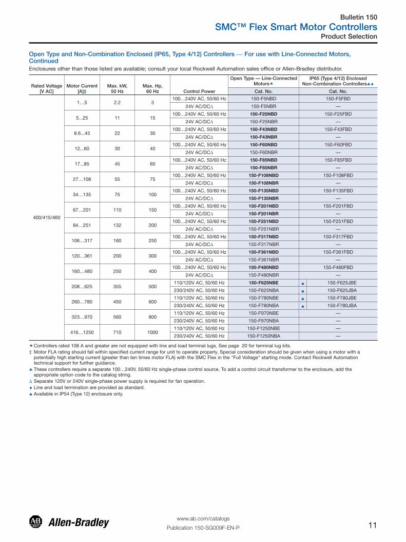
�Controllers rated 108 A and greater are not equipped with line and load terminal lugs. See page 20 for terminal lug kits.‡ Motor FLA rating should fall within specified current range for unit to operate properly. Special consideration should be given when using a motor with a
potentially high starting current (greater than ten times motor FLA) with the SMC Flex in the "Full Voltage" starting mode. Contact Rockwell Automationtechnical support for further guidance.
♣ These controllers require a separate 100…240V, 50/60 Hz single-phase control source. To add a control circuit transformer to the enclosure, add theappropriate option code to the catalog string.
Δ Separate 120V or 240V single-phase power supply is required for fan operation.♦ Line and load termination are provided as standard.♠ Available in IP54 (Type 12) enclosure only.
Open Type and Non-Combination Enclosed (IP65, Type 4/12) Controllers ⎯ For use with Line-Connected MotorsEnclosures other than those listed are available; consult your local Rockwell Automation sales office or Allen-Bradley distributor.
Product Selection

Bulletin 150
SMC™ Flex Smart Motor Controllers
10www.ab.com/catalogs
Publication 150-SG009F-EN-P
Open Type and Non-Combination Enclosed (IP65, Type 4/12) Controllers ⎯ For use with Line-Connected Motors,ContinuedEnclosures other than those listed are available; consult your local Rockwell Automation sales office or Allen-Bradley distributor.
Rated Voltage[V AC]
Motor Current[A]‡
Max. kW,50 Hz
Max. Hp,60 Hz Control Power
Open Type — Line-ConnectedMotors�
IP65 (Type 4/12) EnclosedNon-Combination Controllers♣♦
Cat. No. Cat. No.
230
1…5 1.1 1100…240V AC, 50/60 Hz 150-F5NBD 150-F5FAD
24V AC/DCΔ 150-F5NBR —
5...25 5.5 7.5100…240V AC, 50/60 Hz 150-F25NBD 150-F25FAD
24V AC/DCΔ 150-F25NBR —
8.6...43 11 15100…240V AC, 50/60 Hz 150-F43NBD 150-F43FAD
24V AC/DCΔ 150-F43NBR —
12...60 15 20100…240V AC, 50/60 Hz 150-F60NBD 150-F60FAD
24V AC/DCΔ 150-F60NBR —
17...85 22 30100…240V AC, 50/60 Hz 150-F85NBD 150-F85FAD
24V AC/DCΔ 150-F85NBR —
27…108 30 40100…240V AC, 50/60 Hz 150-F108NBD 150-F108FAD
24V AC/DCΔ 150-F108NBR —
34…135 37 50100…240V AC, 50/60 Hz 150-F135NBD 150-F135FAD
24V AC/DCΔ 150-F135NBR —
67…201 55 75100…240V AC, 50/60 Hz 150-F201NBD 150-F201FAD
24V AC/DCΔ 150-F201NBR —
84…251 75 100100…240V AC, 50/60 Hz 150-F251NBD 150-F251FAD
24V AC/DCΔ 150-F251NBR —
106…317 90 125100…240V AC, 50/60 Hz 150-F317NBD 150-F317FAD
24V AC/DCΔ 150-F317NBR —
120…361 110 150100…240V AC, 50/60 Hz 150-F361NBD 150-F361FAD
24V AC/DCΔ 150-F361NBR —
160…480 132 200100…240V AC, 50/60 Hz 150-F480NBD 150-F480FAD
24V AC/DCΔ 150-F480NBR —
208…625 200 250110/120V AC, 50/60 Hz 150-F625NBE ♠ 150-F625JAE
230/240V AC, 50/60 Hz 150-F625NBA ♠ 150-F625JAA
260…780 250 300110/120V AC, 50/60 Hz 150-F780NBE ♠ 150-F780JAE
230/240V AC, 50/60 Hz 150-F780NBA ♠ 150-F780JAA
323…970 315 400110/120V AC, 50/60 Hz 150-F970NBE —
230/240V AC, 50/60 Hz 150-F970NBA —
416…1250 400 500110/120V AC, 50/60 Hz 150-F1250NBE —
230/240V AC, 50/60 Hz 150-F1250NBA —
�Controllers rated 108 A and greater are not equipped with line and load terminal lugs. See page 20 for terminal lug kits.‡ Motor FLA rating should fall within specified current range for unit to operate properly. Special consideration should be given when using a motor with a
potentially high starting current (greater than ten times motor FLA) with the SMC Flex in the "Full Voltage" starting mode. Contact Rockwell Automationtechnical support for further guidance.
♣ These controllers require a separate 100…240V, 50/60 Hz single-phase control source. To add a control circuit transformer to the enclosure, add theappropriate option code to the catalog string.
Δ Separate 120V or 240V single-phase power supply is required for fan operation.♦ Line and load termination are provided as standard.♠ Available in IP54 (Type 12) enclosure only.
Product Selection
Bulletin 150
SMC™ Flex Smart Motor Controllers
11www.ab.com/catalogs
Publication 150-SG009F-EN-P
Open Type and Non-Combination Enclosed (IP65, Type 4/12) Controllers ⎯ For use with Line-Connected Motors,ContinuedEnclosures other than those listed are available; consult your local Rockwell Automation sales office or Allen-Bradley distributor.
Rated Voltage[V AC]
Motor Current[A]‡
Max. kW,50 Hz
Max. Hp,60 Hz Control Power
Open Type — Line-ConnectedMotors�
IP65 (Type 4/12) EnclosedNon-Combination Controllers♣♦
Cat. No. Cat. No.
400/415/460
1…5 2.2 3100…240V AC, 50/60 Hz 150-F5NBD 150-F5FBD
24V AC/DCΔ 150-F5NBR —
5...25 11 15100…240V AC, 50/60 Hz 150-F25NBD 150-F25FBD
24V AC/DCΔ 150-F25NBR —
8.6...43 22 30100…240V AC, 50/60 Hz 150-F43NBD 150-F43FBD
24V AC/DCΔ 150-F43NBR —
12...60 30 40100…240V AC, 50/60 Hz 150-F60NBD 150-F60FBD
24V AC/DCΔ 150-F60NBR —
17...85 45 60100…240V AC, 50/60 Hz 150-F85NBD 150-F85FBD
24V AC/DCΔ 150-F85NBR —
27…108 55 75100…240V AC, 50/60 Hz 150-F108NBD 150-F108FBD
24V AC/DCΔ 150-F108NBR —
34…135 75 100100…240V AC, 50/60 Hz 150-F135NBD 150-F135FBD
24V AC/DCΔ 150-F135NBR —
67…201 110 150100…240V AC, 50/60 Hz 150-F201NBD 150-F201FBD
24V AC/DCΔ 150-F201NBR —
84…251 132 200100…240V AC, 50/60 Hz 150-F251NBD 150-F251FBD
24V AC/DCΔ 150-F251NBR —
106…317 160 250100…240V AC, 50/60 Hz 150-F317NBD 150-F317FBD
24V AC/DCΔ 150-F317NBR —
120…361 200 300100…240V AC, 50/60 Hz 150-F361NBD 150-F361FBD
24V AC/DCΔ 150-F361NBR —
160…480 250 400100…240V AC, 50/60 Hz 150-F480NBD 150-F480FBD
24V AC/DCΔ 150-F480NBR —
208…625 355 500110/120V AC, 50/60 Hz 150-F625NBE ♠ 150-F625JBE
230/240V AC, 50/60 Hz 150-F625NBA ♠ 150-F625JBA
260…780 450 600110/120V AC, 50/60 Hz 150-F780NBE ♠ 150-F780JBE
230/240V AC, 50/60 Hz 150-F780NBA ♠ 150-F780JBA
323…970 560 800110/120V AC, 50/60 Hz 150-F970NBE —
230/240V AC, 50/60 Hz 150-F970NBA —
416…1250 710 1000110/120V AC, 50/60 Hz 150-F1250NBE —
230/240V AC, 50/60 Hz 150-F1250NBA —
�Controllers rated 108 A and greater are not equipped with line and load terminal lugs. See page 20 for terminal lug kits.‡ Motor FLA rating should fall within specified current range for unit to operate properly. Special consideration should be given when using a motor with a
potentially high starting current (greater than ten times motor FLA) with the SMC Flex in the "Full Voltage" starting mode. Contact Rockwell Automationtechnical support for further guidance.
♣ These controllers require a separate 100…240V, 50/60 Hz single-phase control source. To add a control circuit transformer to the enclosure, add theappropriate option code to the catalog string.
Δ Separate 120V or 240V single-phase power supply is required for fan operation.♦ Line and load termination are provided as standard.♠ Available in IP54 (Type 12) enclosure only.
Product Selection

Bulletin 150
SMC™ Flex Smart Motor Controllers
12www.ab.com/catalogs
Publication 150-SG009F-EN-P
Open Type and Non-Combination Enclosed (IP65, Type 4/12) Controllers ⎯ For use with Line-Connected Motors,ContinuedEnclosures other than those listed are available; consult your local Rockwell Automation sales office or Allen-Bradley distributor.
Rated Voltage[V AC]
Motor Current[A]‡ Max. kW, 50 Hz Max. Hp, 60 Hz Control Power
Open Type — Line-ConnectedMotors�
IP65 (Type 4/12) EnclosedNon-Combination Controllers♣♦
Cat. No. Cat. No.
500/575
1...5 2.2 3100…240V AC, 50/60 Hz 150-F5NCD 150-F5FCD
24V AC/DCΔ 150-F5NCR —
5...25 15 20100…240V AC, 50/60 Hz 150-F25NCD 150-F25FCD
24V AC/DCΔ 150-F25NCR —
8.6...43 22 40100…240V AC, 50/60 Hz 150-F43NCD 150-F43FCD
24V AC/DCΔ 150-F43NCR —
12...60 37 50100…240V AC, 50/60 Hz 150-F60NCD 150-F60FCD
24V AC/DCΔ 150-F60NCR —
17...85 55 75100…240V AC, 50/60 Hz 150-F85NCD 150-F85FCD
24V AC/DCΔ 150-F85NCR —
27…108 75 100100…240V AC, 50/60 Hz 150-F108NCD 150-F108FCD
24V AC/DCΔ 150-F108NCR —
34…135 90 125100…240V AC, 50/60 Hz 150-F135NCD 150-F135FCD
24V AC/DCΔ 150-F135NCR —
67…201 132 200100…240V AC, 50/60 Hz 150-F201NCD 150-F201FCD
24V AC/DCΔ 150-F201NCR —
84…251 160 250100…240V AC, 50/60 Hz 150-F251NCD 150-F251FCD
24V AC/DCΔ 150-F251NCR —
106…317 200 300100…240V AC, 50/60 Hz 150-F317NCD 150-F317FCD
24V AC/DCΔ 150-F317NCR —
120…361 250 350100…240V AC, 50/60 Hz 150-F361NCD 150-F361FCD
24V AC/DCΔ 150-F361NCR —
160…480 315 500100…240V AC, 50/60 Hz 150-F480NCD 150-F480FCD
24V AC/DCΔ 150-F480NCR —
208…625 450 600110/120V AC, 50/60 Hz 150-F625NCE ♠ 150-F625JCE
230/240V AC, 50/60 Hz 150-F625NCA ♠ 150-F625JCA
260…780 560 800110/120V AC, 50/60 Hz 150-F780NCE ♠ 150-F780JCE
230/240V AC, 50/60 Hz 150-F780NCA ♠ 150-F780JCA
323…970 710 1000110/120V AC, 50/60 Hz 150-F970NCE —
230/240V AC, 50/60 Hz 150-F970NCA —
416…1250 900 1300110/120V AC, 50/60 Hz 150-F1250NCE —
230/240V AC, 50/60 Hz 150-F1250NCA —
Rated Voltage[V AC]
Motor Current[A]‡ Max. kW, 50 Hz Max. Hp, 60 Hz Control Power
Open Type — Line-Connected Motors�
Cat. No.
690/Y§
27…108 90 100 100…240V AC, 50/60 Hz 150-F108NZD
34…135 132 175 100…240V AC, 50/60 Hz 150-F135NZD
67…201 160 200 100…240V AC, 50/60 Hz 150-F201NZD
84…251 200 250 100…240V AC, 50/60 Hz 150-F251NZD
106…317 315 400 100…240V AC, 50/60 Hz 150-F317NZD
120…361 355 450 100…240V AC, 50/60 Hz 150-F361NZD
160…480 450 600 100…240V AC, 50/60 Hz 150-F480NZD
208…625 630 800110/120V AC, 50/60 Hz 150-F625NZE
230/240V AC, 50/60 Hz 150-F625NZA
260…780 800 1000110/120V AC, 50/60 Hz 150-F780NZE
230/240V AC, 50/60 Hz 150-F780NZA
323…970 1000 1300110/120V AC, 50/60 Hz 150-F970NZE
230/240V AC, 50/60 Hz 150-F970NZA
416…1250 1200 1600110/120V AC, 50/60 Hz 150-F1250NZE
230/240V AC, 50/60 Hz 150-F1250NZA
�Controllers rated 108 A and greater are not equipped with line and load terminal lugs. See page 20 for terminal lug kits.‡ Motor FLA rating should fall within specified current range for unit to operate properly. Special consideration should be given when using a motor with a potentially
high starting current (greater than ten times motor FLA) with the SMC Flex in the "Full Voltage" starting mode. Contact Rockwell Automation technical support forfurther guidance.
♣ These controllers require a separate 100…240V, 50/60 Hz single-phase control source. To add a control circuit transformer to the enclosure, add the appropriate optioncode to the catalog string.
Δ Separate 120V or 240V single-phase power supply is required for fan operation.♦ Line and load termination are provided as standard.§ To be used only in a Y-type system.♠ Available in IP54 (Type 12) enclosure only.
Product Selection

Bulletin 150
SMC™ Flex Smart Motor Controllers
13www.ab.com/catalogs
Publication 150-SG009F-EN-P
Open Type Controllers ⎯ For use with Delta-Connected Motors
Rated Voltage[V AC] Motor Current [A]‡ Max. kW, 50 Hz Max. Hp, 60 Hz Control Power
Open Type�
Cat. No.
200/208
1.7…8.7 — 2100…240V AC, 50/60 Hz 150-F5NBD
24V AC/DCΔ 150-F5NBR
8.7…43 — 10100…240V AC, 50/60 Hz 150-F25NBD
24V AC/DCΔ 150-F25NBR
14.9…74 — 20100…240V AC, 50/60 Hz 150-F43NBD
24V AC/DCΔ 150-F43NBR
20.8…104 — 30100…240V AC, 50/60 Hz 150-F60NBD
24V AC/DCΔ 150-F60NBR
29.4…147 — 40100…240V AC, 50/60 Hz 150-F85NBD
24V AC/DCΔ 150-F85NBR
47…187 — 60100…240V AC, 50/60 Hz 150-F108NBD
24V AC/DCΔ 150-F108NBR
59…234 — 75100…240V AC, 50/60 Hz 150-F135NBD
24V AC/DCΔ 150-F135NBR
116…348 — 100100…240V AC, 50/60 Hz 150-F201NBD
24V AC/DCΔ 150-F201NBR
145…435 — 150100…240V AC, 50/60 Hz 150-F251NBD
24V AC/DCΔ 150-F251NBR
183…549 — 200100…240V AC, 50/60 Hz 150-F317NBD
24V AC/DCΔ 150-F317NBR
208…625 — 200100…240V AC, 50/60 Hz 150-F361NBD
24V AC/DCΔ 150-F361NBR
277…831 — 300100…240V AC, 50/60 Hz 150-F480NBD
24V AC/DCΔ 150-F480NBR
283…850 — 300110/120V AC, 50/60 Hz 150-F625NBE
230/240V AC, 50/60 Hz 150-F625NBA
300…900 — 300110/120V AC, 50/60 Hz 150-F780NBE
230/240V AC, 50/60 Hz 150-F780NBA
400…1200 — 400110/120V AC, 50/60 Hz 150-F970NBE
230/240V AC, 50/60 Hz 150-F970NBA
533…1600 — 500110/120V AC, 50/60 Hz 150-F1250NBE
230/240V AC, 50/60 Hz 150-F1250NBA
�Controllers rated 108 A and greater are not equipped with line and load terminal lugs. See page 20 for terminal lug kits.‡ Motor FLA rating should fall within specified current range for unit to operate properly. Special consideration should be given when using a motor with a
potentially high starting current (greater than ten times motor FLA) with the SMC Flex in the "Full Voltage" starting mode. Contact Rockwell Automationtechnical support for further guidance.
Δ Separate 120V or 240V single-phase power supply is required for fan operation.
Product Selection

Bulletin 150
SMC™ Flex Smart Motor Controllers
14www.ab.com/catalogs
Publication 150-SG009F-EN-P
Open Type Controllers ⎯ For use with Delta-Connected Motors, Continued
Rated Voltage[V AC] Motor Current [A]‡ Max. kW, 50 Hz Max. Hp, 60 Hz Control Power
Open Type�
Cat. No.
230
1.7…8.7 2.2 2100…240V AC, 50/60 Hz 150-F5NBD
24V AC/DCΔ 150-F5NBR
8.7…43 11 15100…240V AC, 50/60 Hz 150-F25NBD
24V AC/DCΔ 150-F25NBR
14.9…74 22 25100…240V AC, 50/60 Hz 150-F43NBD
24V AC/DCΔ 150-F43NBR
20.8…104 30 40100…240V AC, 50/60 Hz 150-F60NBD
24V AC/DCΔ 150-F60NBR
29.4…147 45 50100…240V AC, 50/60 Hz 150-F85NBD
24V AC/DCΔ 150-F85NBR
47…187 55 60100…240V AC, 50/60 Hz 150-F108NBD
24V AC/DCΔ 150-F108NBR
59…234 75 75100…240V AC, 50/60 Hz 150-F135NBD
24V AC/DCΔ 150-F135NBR
116…348 110 125100…240V AC, 50/60 Hz 150-F201NBD
24V AC/DCΔ 150-F201NBR
145…435 132 150100…240V AC, 50/60 Hz 150-F251NBD
24V AC/DCΔ 150-F251NBR
183…549 160 200100…240V AC, 50/60 Hz 150-F317NBD
24V AC/DCΔ 150-F317NBR
208…625 200 250100…240V AC, 50/60 Hz 150-F361NBD
24V AC/DCΔ 150-F361NBR
277…831 250 350100…240V AC, 50/60 Hz 150-F480NBD
24V AC/DCΔ 150-F480NBR
283…850 250 350110/120V AC, 50/60 Hz 150-F625NBE
230/240V AC, 50/60 Hz 150-F625NBA
300…900 250 350110/120V AC, 50/60 Hz 150-F780NBE
230/240V AC, 50/60 Hz 150-F780NBA
400…1200 400 400110/120V AC, 50/60 Hz 150-F970NBE
230/240V AC, 50/60 Hz 150-F970NBA
533…1600 500 600110/120V AC, 50/60 Hz 150-F1250NBE
230/240V AC, 50/60 Hz 150-F1250NBA
�Controllers rated 108 A and greater are not equipped with line and load terminal lugs. See page 20 for terminal lug kits.‡ Motor FLA rating should fall within specified current range for unit to operate properly. Special consideration should be given when using a motor with a
potentially high starting current (greater than ten times motor FLA) with the SMC Flex in the "Full Voltage" starting mode. Contact Rockwell Automationtechnical support for further guidance.
Δ Separate 120V or 240V single-phase power supply is required for fan operation.
Product Selection

Bulletin 150
SMC™ Flex Smart Motor Controllers
15www.ab.com/catalogs
Publication 150-SG009F-EN-P
Open Type Controllers ⎯ For use with Delta-Connected Motors, Continued
Rated Voltage[V AC] Motor Current [A]‡ Max. kW, 50 Hz Max. Hp, 60 Hz Control Power
Open Type�
Cat. No.
400/415/460
1.7…8.7 4 5100…240V AC, 50/60 Hz 150-F5NBD
24V AC/DCΔ 150-F5NBR
8.7…43 22 30100…240V AC, 50/60 Hz 150-F25NBD
24V AC/DCΔ 150-F25NBR
14.9…74 37 50100…240V AC, 50/60 Hz 150-F43NBD
24V AC/DCΔ 150-F43NBR
20.8…104 55 75100…240V AC, 50/60 Hz 150-F60NBD
24V AC/DCΔ 150-F60NBR
29.4…147 75 100100…240V AC, 50/60 Hz 150-F85NBD
24V AC/DCΔ 150-F85NBR
47…187 90 150100…240V AC, 50/60 Hz 150-F108NBD
24V AC/DCΔ 150-F108NBR
59…234 132 150100…240V AC, 50/60 Hz 150-F135NBD
24V AC/DCΔ 150-F135NBR
116…348 160 250100…240V AC, 50/60 Hz 150-F201NBD
24V AC/DCΔ 150-F201NBR
145…435 250 350100…240V AC, 50/60 Hz 150-F251NBD
24V AC/DCΔ 150-F251NBR
183…549 315 450100…240V AC, 50/60 Hz 150-F317NBD
24V AC/DCΔ 150-F317NBR
208…625 355 500100…240V AC, 50/60 Hz 150-F361NBD
24V AC/DCΔ 150-F361NBR
277…831 450 700100…240V AC, 50/60 Hz 150-F480NBD
24V AC/DCΔ 150-F480NBR
283…850 500 700110/120V AC, 50/60 Hz 150-F625NBE
230/240V AC, 50/60 Hz 150-F625NBA
300…900 500 700110/120V AC, 50/60 Hz 150-F780NBE
230/240V AC, 50/60 Hz 150-F780NBA
400…1200 710 1000110/120V AC, 50/60 Hz 150-F970NBE
230/240V AC, 50/60 Hz 150-F970NBA
533…1600 900 1400110/120V AC, 50/60 Hz 150-F1250NBE
230/240V AC, 50/60 Hz 150-F1250NBA
�Controllers rated 108 A and greater are not equipped with line and load terminal lugs. See page 20 for terminal lug kits.‡ Motor FLA rating should fall within specified current range for unit to operate properly. Special consideration should be given when using a motor with a
potentially high starting current (greater than ten times motor FLA) with the SMC Flex in the "Full Voltage" starting mode. Contact Rockwell Automationtechnical support for further guidance.
Δ Separate 120V or 240V single-phase power supply is required for fan operation.
Product Selection

Bulletin 150
SMC™ Flex Smart Motor Controllers
16www.ab.com/catalogs
Publication 150-SG009F-EN-P
Open Type Controllers ⎯ For use with Delta-Connected Motors, Continued
Rated Voltage[V AC] Motor Current [A]‡ Max. kW, 50 Hz Max. Hp, 60 Hz Control Power
Open Type�
Cat. No.
500/575
1.7…8.7 5.5 7.5100…240V AC, 50/60 Hz 150-F5NCD
24V AC/DCΔ 150-F5NCR
8.7…43 15 40100…240V AC, 50/60 Hz 150-F25NCD
24V AC/DCΔ 150-F25NCR
14.9…74 45 60100…240V AC, 50/60 Hz 150-F43NCD
24V AC/DCΔ 150-F43NCR
20.8…104 55 100100…240V AC, 50/60 Hz 150-F60NCD
24V AC/DCΔ 150-F60NCR
29.4…147 90 150100…240V AC, 50/60 Hz 150-F85NCD
24V AC/DCΔ 150-F85NCR
47…187 132 150100…240V AC, 50/60 Hz 150-F108NCD
24V AC/DCΔ 150-F108NCR
59…234 160 200100…240V AC, 50/60 Hz 150-F135NCD
24V AC/DCΔ 150-F135NCR
116…348 250 300100…240V AC, 50/60 Hz 150-F201NCD
24V AC/DCΔ 150-F201NCR
145…435 315 400100…240V AC, 50/60 Hz 150-F251NCD
24V AC/DCΔ 150-F251NCR
183…549 400 500100…240V AC, 50/60 Hz 150-F317NCD
24V AC/DCΔ 150-F317NCR
208…625 450 600100…240V AC, 50/60 Hz 150-F361NCD
24V AC/DCΔ 150-F361NCR
277…831 560 900100…240V AC, 50/60 Hz 150-F480NCD
24V AC/DCΔ 150-F480NCR
283…850 560 900110/120V AC, 50/60 Hz 150-F625NCE
230/240V AC, 50/60 Hz 150-F625NCA
300…900 630 900110/120V AC, 50/60 Hz 150-F780NCE
230/240V AC, 50/60 Hz 150-F780NCA
400…1200 800 1300110/120V AC, 50/60 Hz 150-F970NCE
230/240V AC, 50/60 Hz 150-F970NCA
533…1600 1100 1600110/120V AC, 50/60 Hz 150-F1250NCE
230/240V AC, 50/60 Hz 150-F1250NCA
�Controllers rated 108 A and greater are not equipped with line and load terminal lugs. See page 20 for terminal lug kits.‡ Motor FLA rating should fall within specified current range for unit to operate properly. Special consideration should be given when using a motor with a
potentially high starting current (greater than ten times motor FLA) with the SMC Flex in the "Full Voltage" starting mode. Contact Rockwell Automationtechnical support for further guidance.
Δ Separate 120V or 240V single-phase power supply is required for fan operation.
Product Selection

Bulletin 150
SMC™ Flex Smart Motor Controllers
17www.ab.com/catalogs
Publication 150-SG009F-EN-P
Combination Line-Connected Controllers — IP65 (Type 4/12) Enclosed with Fusible Disconnect or Circuit Breaker
RatedVoltage[V AC] kW, 50 Hz Hp, 60 Hz
Controller CurrentRating [A] ‡
IP65 (Type 4/12) Enclosed CombinationControllers with Fusible Disconnect�
IP65 (Type 4/12) Enclosed CombinationControllers with Circuit Breaker�
Cat. No.♣ Cat. No.
200
— 0.5 5 152H-F5FHD-33 153H-F5FHD-33
— 0.75 5 152H-F5FHD-34 153H-F5FHD-34
— 1 5 152H-F5FHD-35 153H-F5FHD-35
— 1.5 25 152H-F25FHD-36 153H-F25FHD-36
— 2 25 152H-F25FHD-37 153H-F25FHD-37
— 3 25 152H-F25FHD-38 153H-F25FHD-38
— 5 25 152H-F25FHD-39 153H-F25FHD-39
— 5 25 152H-F25FHD-40 153H-F25FHD-40
— 10 43 152H-F43FHD-41 153H-F43FHD-41
— 15 60 152H-F60FHD-42 153H-F60FHD-42
— 20 85 152H-F85FHD-43 153H-F85FHD-43
— 25 85 152H-F85FHD-44 153H-F85FHD-44
— 30 108 152H-F108FHD-45 153H-F108FHD-45
— 40 135 152H-F135FHD-46 153H-F135FHD-46
— 50 201 152H-F201FHD-47 153H-F201FHD-47
— 60 201 152H-F201FHD-48 153H-F201FHD-48
— 75 251 152H-F251FHD-49 153H-F251FHD-49
— 100 317 152H-F317FHD-50 153H-F317FHD-50
— 125 361 152H-F361FHD-51 153H-F361FHD-51
— 150 480 152H-F480FHD-52 153H-F480FHD-52
— 200 625 Δ 152H-F625JHD-54 Δ 153H-F625JHD-54
— 250 780 Δ 152H-F780JHD-56 Δ 153H-F780JHD-56
230
0.37 0.5 5 152H-F5FAD-33 153H-F5FAD-33
0.55 0.75 5 152H-F5FAD-34 153H-F5FAD-34
0.75 1 5 152H-F5FAD-35 153H-F5FAD-35
1.1 1.5 25 152H-F25FAD-36 153H-F25FAD-36
1.5 2 25 152H-F25FAD-37 153H-F25FAD-37
2.2 3 25 152H-F25FAD-38 153H-F25FAD-38
3.7 5 25 152H-F25FAD-39 153H-F25FAD-39
5.5 7.5 25 152H-F25FAD-40 153H-F25FAD-40
7.5 10 43 152H-F43FAD-41 153H-F43FAD-41
11 15 43 152H-F43FAD-42 153H-F43FAD-42
15 20 60 152H-F60FAD-43 153H-F60FAD-43
18.5 25 85 152H-F85FAD-44 153H-F85FAD-44
22 30 85 152H-F85FAD-45 153H-F85FAD-45
30 40 108 152H-F108FAD-46 153H-F108FAD-46
37 50 135 152H-F135FAD-47 153H-F135FAD-47
45 60 201 152H-F201FAD-48 153H-F201FAD-48
55 75 201 152H-F201FAD-49 153H-F201FAD-49
75 100 251 152H-F251FAD-50 153H-F251FAD-50
90 125 317 152H-F317FAD-51 153H-F317FAD-51
110 150 361 152H-F361FAD-52 153H-F361FAD-52
132 200 480 Δ 152H-F480JAD-54 153H-F480FAD-54
185 250 625 Δ 152H-F625JAD-56 Δ 153H-F625JAD-56
220 300 780 Δ 152H-F780JAD-57 Δ 153H-F780JAD-57
�These controllers require a separate 100…240V, 50/60 Hz single-phase control source. To add a control circuit transformer to the enclosure, add theappropriate option code to the catalog string.
‡ The nominal current rating for the combination package may differ from the controller, based on the horsepower. Consult your local Rockwell Automation salesoffice or Allen-Bradley distributor.
♣ Provided with Class J or L fuse clips as standard.Δ Available in IP54 (Type 12) enclosure only.
Product Selection

Bulletin 150
SMC™ Flex Smart Motor Controllers
18www.ab.com/catalogs
Publication 150-SG009F-EN-P
Combination Line-Connected Controllers — IP65 (Type 4/12) Enclosed with Fusible Disconnect or Circuit Breaker, Cont.These controllers include line and load terminations. Enclosures other than those listed are available; consult your local Rockwell Automationsales office or Allen-Bradley distributor. All Bulletin 153 catalog numbers are supplied with thermal magnetic circuit breakers.
The fusible disconnects do not come with fuses.
RatedVoltage[V AC] kW, 50 Hz Hp, 60 Hz
Controller CurrentRating [A] ‡
IP65 (Type 4/12) Enclosed CombinationControllers with Fusible Disconnect�
IP65 (Type 4/12) Enclosed CombinationControllers with Circuit Breaker�
Cat. No.♣ Cat. No.
400/460
0.37 0.5 5 152H-F5FBD-33 153H-F5FBD-330.55 0.75 5 152H-F5FBD-34 153H-F5FBD-340.75 1 5 152H-F5FBD-35 153H-F5FBD-351.1 1.5 5 152H-F5FBD-36 153H-F5FBD-361.5 2 5 152H-F5FBD-37 153H-F5FBD-372.2 3 5 152H-F5FBD-38 153H-F5FBD-383.7 5 25 152H-F25FBD-39 153H-F25FBD-395.5 7.5 25 152H-F25FBD-40 153H-F25FBD-407.5 10 25 152H-F25FBD-41 153H-F25FBD-4111 15 25 152H-F25FBD-42 153H-F25FBD-4215 20 43 152H-F43FBD-43 153H-F25FBD-43
18.5 25 43 152H-F43FBD-44 153H-F43FBD-4422 30 43 152H-F43FBD-45 153H-F43FBD-4530 40 60 152H-F60FBD-46 153H-F60FBD-4637 50 85 152H-F85FBD-47 153H-F85FBD-4745 60 85 152H-F85FBD-48 153H-F85FBD-4855 75 108 152H-F108FBD-49 153H-F108FBD-4975 100 135 152H-F135FBD-50 153H-F135FBD-5090 125 201 152H-F201FBD-51 153H-F201FBD-51110 150 201 152H-F201FBD-52 153H-F201FBD-52132 200 251 152H-F251FBD-54 153H-F251FBD-54160 250 317 152H-F317FBD-56 153H-F317FBD-56200 300 361 152H-F361FBD-57 153H-F361FBD-57250 350 480 152H-F480FBD-58 153H-F480FBD-58250 400 480 Δ 152H-F480JBD-59 153H-F480FBD-59355 500 625 Δ 152H-F625JBD-61 Δ 153H-F625JBD-61450 600 780 Δ 152H-F780JBD-62 Δ 153H-F780JBD-62
500/575
0.55 0.75 5 152H-F5FCD-34 153H-F5FCD-340.75 1 5 152H-F5FCD-35 153H-F5FCD-351.1 1.5 5 152H-F5FCD-36 153H-F5FCD-361.5 2 5 152H-F5FCD-37 153H-F5FCD-372.2 3 5 152H-F5FCD-38 153H-F5FCD-383.7 5 25 152H-F25FCD-39 153H-F25FCD-395.5 7.5 25 152H-F25FCD-40 153H-F25FCD-407.5 10 25 152H-F25FCD-41 153H-F25FCD-4111 15 25 152H-F25FCD-42 153H-F25FCD-4215 20 43 152H-F43FCD-43 153H-F43FCD-43
18.5 25 43 152H-F43FCD-44 153H-F43FCD-4422 30 43 152H-F43FCD-45 153H-F43FCD-4522 40 43 152H-F43FCD-46 153H-F43FCD-4637 50 60 152H-F60FCD-47 153H-F60FCD-4745 60 85 152H-F85FCD-48 153H-F85FCD-4855 75 85 152H-F85FCD-49 153H-F85FCD-4975 100 108 152H-F108FCD-50 153H-F108FCD-5090 125 135 152H-F135FCD-51 153H-F135FCD-51110 150 201 152H-F201FCD-52 153H-F201FCD-52132 200 201 152H-F201FCD-54 153H-F201FCD-54160 250 251 152H-F251FCD-56 153H-F251FCD-56200 300 317 152H-F317FCD-57 153H-F317FCD-57250 350 361 152H-F361FCD-58 153H-F361FCD-58295 400 480 Δ 152H-F480JCD-59 153H-F480FCD-59315 450 480 Δ 152H-F480JCD-60 153H-F480FCD-60315 500 480 Δ 152H-F480JCD-61 153H-F480FCD-61450 600 625 Δ 152H-F625JCD-62 Δ 153H-F625JCD-62560 800 780 Δ 152H-F780JCD-65 Δ 153H-F780JCD-65
�These controllers require a separate 100…240V, 50/60 Hz single-phase control source. To add a control circuit transformer to the enclosure, add the appropriateoption code to the catalog string.
‡ The nominal current rating for the combination package may differ from the controller, based on the horsepower. Consult your local Rockwell Automation sales officeor Allen-Bradley distributor.
♣ Provided with Class J or L fuse clips as standard.
Δ Available in IP54 (Type 12) enclosure only.
Product Selection

Bulletin 150
SMC™ Flex Smart Motor Controllers
19www.ab.com/catalogs
Publication 150-SG009F-EN-P
Control Options (open and enclosed)
Option DescriptionCat. No.
Modification
Pump Control Provides smooth motor acceleration and deceleration, reducing surges caused by the starting and stopping of centrifugalpumps. Starting time is adjustable from 0…30 s, and stopping time is adjustable from 0…120 s. B�
Braking Control Provides Smart Motor Braking (SMB), Accu-Stop, and Slow Speed with Braking. D�
Enclosed Options
Option DescriptionCat. No.
Modification
Push Buttons
Start-Stop Push Button -1
Start-Stop Push Button with H-O-A Selector Switch -1F
Soft Stop Push Button‡ 1XA
Pump Stop Push Button‡ 1XB
Slow Speed Push Button‡ 1XC
Brake Push Button‡ 1XD
Accu-Stop/Slow Speed Push Button‡ 1XE
Selector SwitchHand-Off-Auto Selector Switch -3
SMC-Off-Bypass Selector Switch -3B ∇
Pilot Lights
Transformer Pilot Light - Green Power On Indicator -4G
Transformer Pilot Light - Red Run Indicator -4R
Push-to-Test Pilot Light - Red Run Indicator -5R
Control Circuit Transformer
Control Circuit Transformer (fused primary and secondary) -6P
Additional 100VA Control Circuit Transformer (fused primary and secondary) -6PX
1000VA Control Circuit Transformer (fused primary and secondary) -6PK
1600VA Control Circuit Transformer (fused primary and secondary) -6PL
2000VA Control Circuit Transformer (fused primary and secondary) -6PM
Protective Modules
480V Line Side Protective Module-8L
600V Line Side Protective Module
480V Load Side Protective Module-8M
600V Load Side Protective Module
480V Both Line and Load Side Protective Modules-8B
600V Both Line and Load Side Protective Modules
Human Interface Module Door-mounted, Full Numeric (Type 4/12) -HC3
Communication Module
RS-485 -20S
DeviceNet -20D
Ethernet/IP -20E
Control Net -20C
ProfiBUS -20P
Disconnect AuxiliaryN.O. disconnect auxiliary mounted on operating mechanism -98
N.C. disconnect auxiliary mounted on operating mechanism -99
Circuit Breaker AuxiliaryInternal N.O. circuit breaker auxiliary -98X
Internal N.C. circuit breaker auxiliary -99X
Service Entrance Label Service Entrance Label -SEL
Oil Pump Starter Bulletin 509 NEMA Size 1starter and Bulletin 592 solid-state overload -OPS
�Add the designated letter to the end of the cat. no. Example: To add the Pump Control option: Cat. No. 150-F361NBDB or Cat. No. 152H-F361FBDB-57.‡ Option push buttons are available only when the corresponding option module is selected. Example: Cat. No. 150-F108FBDB-1XB.∇ Bypass contactor and overload are not included with this option. A -NB or -BP needs to be added to the catalog string to add these devices.
Product Selection

Bulletin 150
SMC™ Flex Smart Motor Controllers
20www.ab.com/catalogs
Publication 150-SG009F-EN-P
Option DescriptionCat. No.
Modification
NEMA Bypass Contactor andOverload Relay
5…43 A
-NB
60…85 A
108…135 A
201…251 A
317…361 A
480 A
NEMA Isolation Contactor
5…43 A
-NI
60…85 A
108…135 A
201…251 A
317…361 A
480 A
MCS Bypass Contactor andOverload Relay
5…43 A
-BP
60…85 A
108…135 A
201…251 A
317…361 A
480 A
Enclosed Options, Continued
Accessories
Protective Modules�Protective modules must not be placed on the load side of a device when using an inside-the-delta connection or with Pump, Braking, orLinerar Speed control.
Current Rating [A] DescriptionField Modification
Cat. No.
5…85480V Protective Module
150-F84
90...520 150-F84L
5…85600V Protective Module
150-F86
90…520 150-F86L
�The same protective module mounts on the line or load side of the SMC Flex. For applications requiring both line and load side protection, two protectivemodules must be ordered.
Terminal Lug Kits (108…1250 A)
CurrentRating [A] ‡ Wire Size
Total No. of Line ControllerTerminal Lugs
Possible Each Side
Pkg. Qty. Cat. No.Line Side Load Side
108…135Δ #6…250 MCM AWG16 mm2…120 mm2
3 3
3
199-LF1201…251Δ 6 6
317…480Δ #4…500 MCM AWG25 mm2…240 mm2 6 6 199-LG1
625…780 2/0…500 MCM AWG 6 6 100-DL630
970 4/0…500 MCM AWG 3 3 100-DL860
1250♣2/0…500 MCM AWG 3 3 100-DL630
4/0…500 MCM AWG 3 3 100-DL860
Line and Load terminals are provided as standard on enclosed SMCs.‡ 5…85 A units have box lugs standard. No additional lugs are required.♣ The 1250 A device requires (1) 100-DL630 and (1) 100-DL860 per connection.Δ When a multi-conductor lug is required, refer to the User Manual for appropriate lug catalog number.
Modifications/Accessories

Bulletin 150
SMC™ Flex Smart Motor Controllers
21www.ab.com/catalogs
Publication 150-SG009F-EN-P
IEC Terminal Covers
Description§ Package QuantityField Modification
Cat. No.
IEC line or load terminal covers for 108 and 135 A devices.Dead front protection 1 150-TC1
IEC line or load terminal covers for 201…251 A devices. Dead front protection 1 150-TC2
IEC line or load terminal covers for 317…480 A devices. Dead front protection 1 150-TC3
§ 5…85 A units have terminal guards standard. No additional terminal guards are required.
Human Interface and Communication Modules
Description Cat. No.
Hand-HeldHuman Interface Modules
LCD Display, Full Numeric Keypad� 20-HIM-A3
LCD Display, Programmer Only� 20-HIM-A5
Door-MountedHuman Interface Modules
Remote (Panel Mount) LCD Display, Full Numeric Keypad 20-HIM-C3S
LCD Display, Programmer Only HIM (includes 3 m cable) 20-HIM-C5S
Human Interface ModuleInterface Cables
PowerFlex HIM Interface Cable, 1 m (39 in) 20-HIM-H10
Cable Kit (Male-Female) 0.33 m (1.1 ft) 1202-H03
Cable Kit (Male-Female) 1 m (3.3 ft) 1202-H10
Cable Kit (Male-Female) 3 m (9.8 ft) 1202-H30
Cable Kit (Male-Female) 9 m (29.5 ft) 1202-H90
DPI/SCANport™ One to Two Port Splitter Cable 1203-S03
Description (IP30/Type 1) For Use With
Communication Modules
RS485 DF1 Communication Adapter
Bulletin 150 SMC-Flex
20-COMM-S
PROFIBUS™ DP Communication Adapter 20-COMM-P
ControlNet™ Communication Adapter (Coax) 20-COMM-C
Interbus™ Communication Adapter 20-COMM-I
Modbus/TCP Communication Adapter 20-COMM-M
DeviceNet™ Communication Adapter 20-COMM-D
EtherNet/IP™ Communication Adapter 20-COMM-E
HVAC Communication Adapter 20-COMM-H
ControlNet™ Communication Adapter (Fiber) 20-COMM-Q
DriveTools™ Programming Software WIN NT/2000/XP 9303-4DTE01ENE
DriveTools™ Sp Programming Software WIN NT/2000/XP 9303-4DTS01ENE
AnaCANda™ RS-232 to DPI PC Interface Serial 1203-SSS
DPI to USB PC Interface USB 1203-USB
�Requires a 20-HIM-H10 cable to connect to the SMC Flex.
Accessories
Bulletin 150
SMC™ Flex Smart Motor Controllers
22www.ab.com/catalogs
Publication 150-SG009F-EN-P
Specifications
Functional Design Specifications
Standard Features
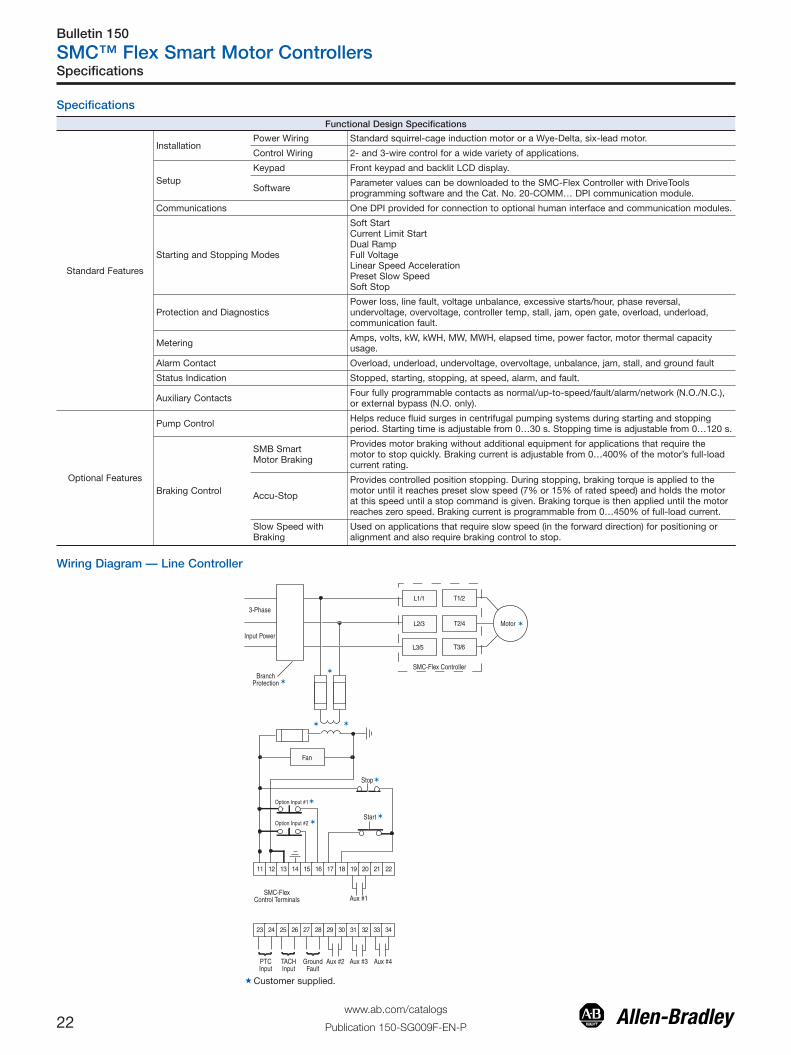
InstallationPower Wiring Standard squirrel-cage induction motor or a Wye-Delta, six-lead motor.
Control Wiring 2- and 3-wire control for a wide variety of applications.
SetupKeypad Front keypad and backlit LCD display.
Software Parameter values can be downloaded to the SMC-Flex Controller with DriveToolsprogramming software and the Cat. No. 20-COMM… DPI communication module.
Communications One DPI provided for connection to optional human interface and communication modules.
Starting and Stopping Modes
Soft StartCurrent Limit StartDual RampFull VoltageLinear Speed AccelerationPreset Slow SpeedSoft Stop
Protection and DiagnosticsPower loss, line fault, voltage unbalance, excessive starts/hour, phase reversal,undervoltage, overvoltage, controller temp, stall, jam, open gate, overload, underload,communication fault.
Metering Amps, volts, kW, kWH, MW, MWH, elapsed time, power factor, motor thermal capacityusage.
Alarm Contact Overload, underload, undervoltage, overvoltage, unbalance, jam, stall, and ground fault
Status Indication Stopped, starting, stopping, at speed, alarm, and fault.
Auxiliary Contacts Four fully programmable contacts as normal/up-to-speed/fault/alarm/network (N.O./N.C.),or external bypass (N.O. only).
Optional Features
Pump Control Helps reduce fluid surges in centrifugal pumping systems during starting and stoppingperiod. Starting time is adjustable from 0…30 s. Stopping time is adjustable from 0…120 s.
Braking Control
SMB SmartMotor Braking
Provides motor braking without additional equipment for applications that require themotor to stop quickly. Braking current is adjustable from 0…400% of the motor’s full-loadcurrent rating.
Accu-Stop
Provides controlled position stopping. During stopping, braking torque is applied to themotor until it reaches preset slow speed (7% or 15% of rated speed) and holds the motorat this speed until a stop command is given. Braking torque is then applied until the motorreaches zero speed. Braking current is programmable from 0…450% of full-load current.
Slow Speed withBraking
Used on applications that require slow speed (in the forward direction) for positioning oralignment and also require braking control to stop.
Wiring Diagram — Line Controller
3-Phase
Input Power
BranchProtection
SMC-Flex Controller
Motor
Fan
Option Input #1
Option Input #2
Stop
Start
SMC-FlexControl Terminals Aux #1
PTCInput
TACHInput
GroundFault
Aux #2 Aux #3 Aux #4
�Customer supplied.
Specifications

Bulletin 150
SMC™ Flex Smart Motor Controllers
23www.ab.com/catalogs
Publication 150-SG009F-EN-P
Electrical RatingsDeviceRating UL/CSA/NEMA IEC
Power Circuit
Rated Operation Voltage480V 200…480V AC (–15%, +10%) 200…415V600V 200…600V AC (–15%, +10%) 200…500V690V 230…600V AC (–15%, +10%) 230…690V/Y (–15%, +10%)
Rated Insulation Voltage480V
N/A500V
600V 500V690V 690V
Rated Impulse Voltage480V
N/A 6000V600V690V
Dielectric Withstand480V
2200V AC 2500V600V690V
Repetitive Peak InverseVoltage Rating
480V 1400V 1400V600V 1600V 1600V690V 1800V 1800V
Operating Frequency All 50/60 Hz
Utilization Category5…480 A MG 1 AC-53B:3.0-50:1750
625…1250 A MG 1 AC-53B:3.0-50:3550
Protection Against ElectricalShock
5…85 AN/A
IP20108…480 A IP2X (with terminal covers)
625…1250 A IP00 (open device)
DV/DT Protection480V & 600V RC Snubber Network
690V None
Transient Protection480V & 600V Metal Oxide Varistors: 220 Joules
690V None
Control Circuit
Rated Operational Voltage♣5…480 A 100…240V AC or 24V AC/DC
625…1250 A 110/120V AC and 230/240V ACRated Insulation Voltage All N/A 240VRated Impulse Voltage All N/A 3000VDielectric Withstand All 1600V AC 2000VOperating Frequency All 50/60 HzInput onstate voltage minimum 85V AC, 19.2V DC / 20.4V ACInput onstate current 20 mA @120V AC / 40 mA @ 240V AC, 7.6 mA @ 24V AC/DCInput offstate voltage maximum 50V AC, 10V DC / 12V ACInput offstate current @ input offstatevoltage <10 mA AC, <3 mA DC
♣ 690V power is only available with 100…240V control.
Specifications

Bulletin 150
SMC™ Flex Smart Motor Controllers
24www.ab.com/catalogs
Publication 150-SG009F-EN-P
Electrical Ratings
Short-CircuitProtection
SCPD Performance 200…600V Type 1♣Δ
SCCR List�Max. StandardAvailable Fault
Max. StandardFuse [A]‡
Max. StandardAvailable Fault
Max. CircuitBreaker [A]
Max. HighFault
Max. Fuse [A]§
Line Device OperationalCurrent Rating [A]
5 5 kA 20 5 kA 20 70 kA 1025 5 kA 100 5 kA 100 70 kA 5043 10 kA 150 10 kA 150 70 kA 9060 10 kA 225 10 kA 225 70 kA 12585 10 kA 300 10 kA 300 70 kA 175108 10 kA 400 10 kA 300 70 kA 200135 10 kA 500 10 kA 400 70 kA 225201 18 kA 600 18 kA 600 70 kA 350251 18 kA 700 18 kA 700 70 kA 400317 30 kA 800 30 kA 800 69 kA 500361 30 kA 1000 30 kA 1000 69 kA 600480 42 kA 1200 42 kA 1200 69 kA 800625 42 kA 1600 42 kA 1600 74 kA 1600780 42 kA 1600 42 kA 2000 74 kA 1600970 85 kA 2500 85 kA 2500 85 kA 2500
1250 85 kA 3000 85 kA 3200 85 kA 3000
Delta Device OperationalCurrent Rating [A]
8.7 5 kA 35 5 kA 35 70 kA 17.543 5 kA 150 5 kA 150 70 kA 9074 10 kA 300 10 kA 300 70 kA 150104 10 kA 400 10 kA 400 70 kA 200147 10 kA 400 10 kA 400 70 kA 200187 10 kA 600 10 kA 500 70 kA 300234 10 kA 700 10 kA 700 70 kA 400348 18 kA 1000 18 kA 1000 70 kA 600435 18 kA 1200 18 kA 1200 70 kA 800549 30 kA 1600 30 kA 1600 69 kA 1000625 30 kA 1600 30 kA 1600 69 kA 1200831 42 kA 1600 30 kA 1600 69 kA 1600850 42 kA 1600 42 kA 2000 74 kA 1600900 42 kA 1600 42 kA 2000 74 kA 1600
1200 85 kA 3000 85 kA 3200 85 kA 30001600 85 kA 3000 85 kA 3200 85 kA 3000
SCPD Performance 690V Type 1♣
SCCR List�DeviceRating Max. Standard Available Fault Max. Ampere Tested — North
American StyleMax. Ampere Tested —
European Style
Maximum FLC
108 70 kA A070URD33xxx500 6,9 gRB 73xxx400 6,6URD33xxx500
135 70 kA A070URD33xxx500 6,9 gRB 73xxx400 6,6URD33xxx500
201 70 kA A070URD33xxx700 6,9 gRB 73xxx6306,6URD33xxx700
251 70 kA A070URD33xxx700 6,9 gRB 73xxx6306,6URD33xxx700
317 70 kA A070URD33xxx900 6,9 gRB 73xxx8006,6URD33xxx900
361 70 kA A070URD33xxx900 6,9 gRB 73xxx8006,6URD33xxx900
480 70 kA A070D33xxx1250A100URD73xxx1250
9 URD 73xxx12506,6URD33xxx1250
625 70 kA A070URD33xxx1400 6,6URD33xxx1400780 70 kA A070URD33xxx1400 6,6URD33xxx1400
970 85 kA Two fuses in parallelA070URD33xxx1250
Two fuses in parallel6,6URD33xxx1250
1250 85 kA Two fuses in parallelA070URD33xxx1250
Two fuses in parallel6,6URD33xxx1250
�Consult local codes for proper sizing of short circuit protection.‡ Non-time delay fuses (K5 — 5…480V (8.7…831 A) devices; Class L — 625…1250V (850…1600 A) devices).§ High capacity fault rating when used with time delay class CC, J, or L fuses.♣ Type 1 performance/protection indicates that, under a short-circuit condition, the fused or circuit breaker-protected starter shall cause no danger to persons or
installation but may not be suitable for further service without repair or replacement.Δ For short-circuit current rating (SCCR) for enclosed panel with external bypass or isolation contactor, see the Industrial Controls catalog website:
www.ab.com/catalogs.
Specifications
Bulletin 150
SMC™ Flex Smart Motor Controllers
25www.ab.com/catalogs
Publication 150-SG009F-EN-P
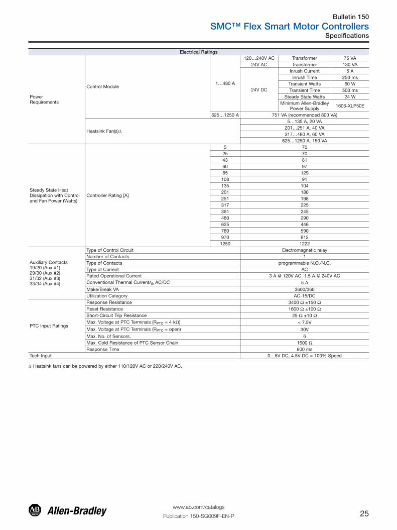
Electrical Ratings
PowerRequirements
Control Module1…480 A
120…240V AC Transformer 75 VA24V AC Transformer 130 VA
24V DC
Inrush Current 5 AInrush Time 250 ms
Transient Watts 60 WTransient Time 500 ms
Steady State Watts 24 WMinimum Allen-Bradley
Power Supply 1606-XLP50E
625…1250 A 751 VA (recommended 800 VA)
Heatsink Fan(s)Δ
5…135 A, 20 VA201…251 A, 40 VA317…480 A, 60 VA
625…1250 A, 150 VA
Steady State HeatDissipation with Controland Fan Power (Watts)
Controller Rating [A]
5 7025 7043 8160 9785 129
108 91135 104201 180251 198317 225361 245480 290625 446780 590970 8121250 1222
Auxiliary Contacts19/20 (Aux #1)29/30 (Aux #2)31/32 (Aux #3)33/34 (Aux #4)
Type of Control Circuit Electromagnetic relayNumber of Contacts 1Type of Contacts programmable N.O./N.C.Type of Current ACRated Operational Current 3 A @ 120V AC, 1.5 A @ 240V ACConventional Thermal CurrentIth AC/DC 5 AMake/Break VA 3600/360Utilization Category AC-15/DC
PTC Input Ratings
Response Resistance 3400 Ω ±150 ΩReset Resistance 1600 Ω ±100 ΩShort-Circuit Trip Resistance 25 Ω ±10 ΩMax. Voltage at PTC Terminals (RPTC = 4 kΩ) < 7.5V
Max. Voltage at PTC Terminals (RPTC = open) 30VMax. No. of Sensors. 6Max. Cold Resistance of PTC Sensor Chain 1500 ΩResponse Time 800 ms
Tach Input 0…5V DC, 4.5V DC = 100% Speed
Δ Heatsink fans can be powered by either 110/120V AC or 220/240V AC.
Specifications

Bulletin 150
SMC™ Flex Smart Motor Controllers
26www.ab.com/catalogs
Publication 150-SG009F-EN-P
Mechanical
Resistance to Vibration
Operational All 1.0 G Peak, 0.15 mm (0.006 in.) displacement
Non-Operational5…480 A 2.5 G Peak, 0.38 mm (0.015 in.) displacement
625…1250 A 1.0 G Peak, 0.15 mm (0.006 in.) displacement
Resistance to Shock
Operational
5…85 A 15 G
108…480 A 5.5 G
625…1250 A 4 G
Non-Operational
5…85 A 30 G
108…480 A 25 G
625…1250 A 12 G
Construction
Power Poles 5…85 A Heatsink thyristor modular design
Power Poles 108…1250 A Heatsink hockey puck thyristor modular design
Control Modules Thermoset and Thermoplastic Moldings
Metal Parts Plated Brass, Copper, or Painted Steel
Terminals
Power Terminals
5…85 A
Cable size — Line Upper — 2.5…95 mm2 (14…3/0 AWG)Line Lower — 0.8…2.5 mm2 (18…14 AWG)Load Upper — 2.5…50 mm2 (14…1 AWG)
Load Lower — 0.8…2.5 mm2 (18…14 AWG)Tightening torque — 14.7 N•m (130 lb.-in.)
108…135 A One M10 x 1.5 diameter hole per power pole
201…251 A Two M10 x 1.5 diameter holes per power pole
317…480 A Two M12 x 1.75 diameter holes per power pole
625…1250 A Two 13.5 mm (0.53 in.) diameter holes per power pole
Power Terminal Markings NEMA, CENELEC EN50 012
Control Terminals M3 screw clamp Clamping yoke connection
Other
EMC Emission Levels Conducted Radio Frequency EmissionsRadiated Emissions
Class AClass A
EMC Immunity Levels
Electrostatic DischargeRadio Frequency Electromagnetic FieldFast TransientSurge Transient
8 kV Air DischargePer EN/IEC 60947-4-2Per EN/IEC 60947-4-2Per EN/IEC 60947-4-2
Overload Characteristics
Current Range [A]
Line Delta
5 1...5 1.7…9
25 5...25 8.6…43
43 8.6...43 14.8…75
60 12...60 20.8…104
85 17...85 29.4…147
108 27…108 47…187
135 34…135 59…234
201 67…201 116…348
251 84…251 145…435
317 106…317 183…549
361 120…361 208…625
480 160…480 277…831
625 208…625 283…850
780 260…780 300…900
970 323…970 400…1200
1250 416…1250 533…1600
Trip ClassesTrip Current RatingNumber of Poles
10, 15, 20, and 30117% of Motor FLC
3
Certifications Open-Type Controllers CE Marked Per Low Voltage Directive 73/23/EEC, 93/68/EECUL Listed (File No. E96956)
Environmental
Operating Temperature Range -5…+50 °C (23…+122 °F) (open)-5…+40 °C (23…+104 °F) (enclosed)
Storage and Transportation Temperature Range -20…+75 °C (-4…167 °F)Altitude 2000 m (6560 ft)Humidity 5…95% (non-condensing)Pollution Degree 2
Specifications

Bulletin 150
SMC™ Flex Smart Motor Controllers
27www.ab.com/catalogs
Publication 150-SG009F-EN-P
Approximate Dimensions and Shipping WeightsOpen Type ControllersDimensions are in millimeters (inches). Dimensions are not intended for manufacturing purposes.
Rating [A] Height Width Depth Weight
5…85 321(12.6)
150(5.9)
203(8.0)
5.7 kg(12.6 lbs)
108…135 443.7(17.47)
196.4(7.74)
205.2(8.08)
15.0 kg(33 lbs).
201…251 560(22.05)
225(8.86)
253.8(9.99)
30.4 kg(67 lbs).
317…480 600(23.62)
290(11.42)
276.5(10.89)
45.8 kg(101 lbs)
625…780 1041.1(41.0)
596.9(23.5)
346.2(13.63)
179 kg(395 lbs)
970…1250 1041.1(41.0)
596.9(23.5)
346.2(13.63)
224 kg(495 lbs)
Enclosed-Type Line-Connected ControllersFactory-installed options may affect enclosure size requirements.Exact dimensions can be obtained after order entry. Please consult your local Rockwell Automation sales office or Allen-Bradley distributor.Dimensions are in millimeters (inches). Dimensions are not intended for manufacturing purposes.
A
B
D
E
F
C
Figure 1 — Wall-Mount
B
ACD E
F
Figure 2 — Wall-Mount
B
A
C
Figure 3 — Floor-Mount
B
A
CLIFTING ANGLE
Figure 4 — Floor-Mount
Approximate Dimensions

Bulletin 150
SMC™ Flex Smart Motor Controllers
28www.ab.com/catalogs
Publication 150-SG009F-EN-P
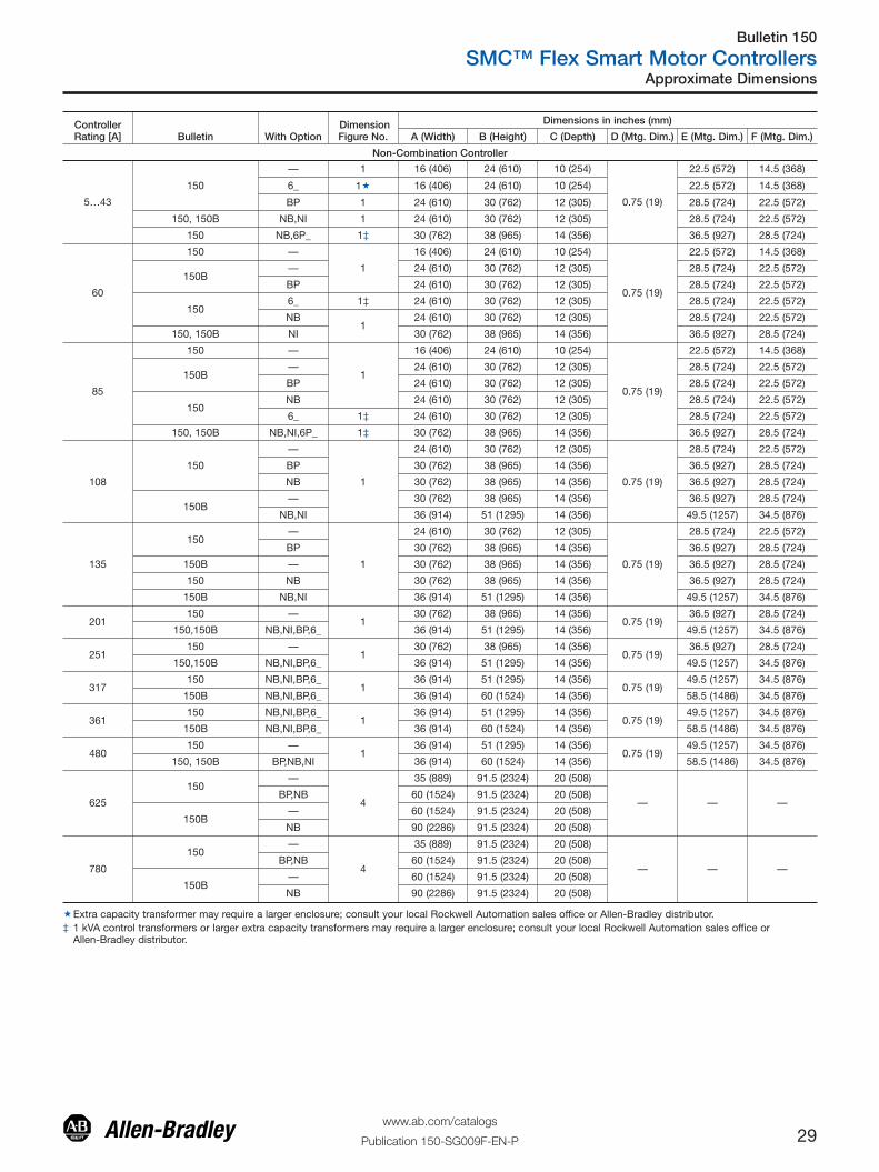
Approximate Dimensions
ControllerRating [A] Bulletin With Option
DimensionFigure No.
Dimensions in inches (mm)
A (Width) B (Height) C (Depth) D (Mtg. Dim.) E (Mtg. Dim.) F (Mtg. Dim.)
SMC-Flex Combination Controller
5…25 152H,152B,153H,153B—
116 (406) 24 (610) 10 (254)
0.75 (19)22.5 (572) 14.5 (368)
BP,NB,NI,6_ 24 (610) 30 (762) 12 (305) 28.5 (724) 22.5 (572)
43 152H,152B,153H,153B
—
1
16 (406) 24 (610) 10 (254)
0.75 (19)
22.5 (572) 14.5 (368)
BP, 6_ 24 (610) 30 (762) 12 (305) 28.5 (724) 22.5 (572)
NI, NB 30 (762) 38 (965) 14 (356) 36.5 (927) 28.5 (724)
60
153H,153B —
1
16 (406) 24 (610) 10 (254)
0.75 (19)
22.5 (572) 14.5 (368)
152H, 153H,153B 6_ 24 (610) 30 (762) 12 (305) 28.5 (724) 22.5 (572)
152H,152B — 24 (610) 30 (762) 12 (305) 28.5 (724) 22.5 (572)
152H,152B,153H,153B NI, NB 30 (762) 38 (965) 14 (356) 36.5 (927) 28.5 (724)
85
153H,153B —
1
16 (406) 24 (610) 10 (254)
0.75 (19)
22.5 (572) 14.5 (368)
152H,152B — 24 (610) 30 (762) 12 (305) 28.5 (724) 22.5 (572)
152H,153H,153B 6_ 24 (610) 30 (762) 12 (305) 28.5 (724) 22.5 (572)
153HBP 24 (610) 30 (762) 12 (305) 28.5 (724) 22.5 (572)
BP , 6_ 30 (762) 38 (965) 14 (356) 36.5 (927) 28.5 (724)
152H,152B,153B BP,NB,NI 30 (762) 38 (965) 14 (356) 36.5 (927) 28.5 (724)
108152H,153H
—
1
30 (762) 38 (965) 14 (356)
0.75 (19)
36.5 (927) 28.5 (724)
6_ 30 (762) 38 (965) 14 (356) 36.5 (927) 28.5 (724)
152H,152B,153H,153B BP, NB,NI 36 (914) 51 (1295) 14 (356) 49.5 (1257) 34.5 (876)
135152H,153H
—
1
30 (762) 38 (965) 14 (356)
0.75 (19)
36.5 (927) 28.5 (724)
6_ 30 (762) 38 (965) 14 (356) 36.5 (927) 28.5 (724)
152H,152B,153H,153B BP, NB,NI 36 (914) 51 (1295) 14 (356) 49.5 (1257) 34.5 (876)
201152H,153H
—
1
30 (762) 38 (965) 14 (356)
0.75 (19)
36.5 (927) 28.5 (724)
6_ 30 (762) 38 (965) 14 (356) 36.5 (927) 28.5 (724)
152H,152B,153H,153B BP, NB,NI 36 (914) 51 (1295) 14 (356) 49.5 (1257) 34.5 (876)
251152H,153H
—
1
30 (762) 38 (965) 14 (356)
0.75 (19)
36.5 (927) 28.5 (724)
6_ 30 (762) 38 (965) 14 (356) 36.5 (927) 28.5 (724)
152H,152B,153H,153B BP, NB,NI 36 (914) 51 (1295) 14 (356) 49.5 (1257) 34.5 (876)
317
153H
—
1
36 (914) 51 (1295) 14 (356)
0.75 (19)
49.5 (1257) 34.5 (876)
6_ 36 (914) 51 (1295) 14 (356) 49.5 (1257) 34.5 (876)
BP,NB 36 (914) 60 (1524) 14 (356) 58.5 (1486) 34.5 (876)
153B — 36 (914) 60 (1524) 14 (356) 58.5 (1486) 34.5 (876)
152H,152B—
238 (965) 60 (1524) 17 (431)
33.88 (861)1.75 (45) 61.69 (1567)
6_ 38 (965) 60 (1524) 17 (431) 1.75 (45) 61.69 (1567)
152H,152B,153B NB,NI 3 40 (1016) 84 (2134) 18 (457) — — —
361
153H
—
1
36 (914) 51 (1295) 14 (356)
0.75 (19)
49.5 (1257) 34.5 (876)
6_ 36 (914) 51 (1295) 14 (356) 49.5 (1257) 34.5 (876)
BP 36 (914) 60 (1524) 14 (356) 58.5 (1486) 34.5 (876)
153B — 36 (914) 60 (1524) 14 (356) 58.5 (1486) 34.5 (876)
152H, 152B —2
38 (965) 60 (1524) 17 (431)33.88 (861)
1.75 (45) 61.69 (1567)
152H 6_ 38 (965) 60 (1524) 17 (431) 1.75 (45) 61.69 (1567)
152H,152B,153H,153B NB,NI 3 40 (1016) 84 (2134) 18 (457) — — —
480
153H—
136 (914) 51 (1295) 14 (356)
0.75 (19)
49.5 (1257) 34.5 (876)
6_ 36 (914) 51 (1295) 14 (356) 49.5 (1257) 34.5 (876)
153H,153B BP,NI 1‡ 36 (914) 60 (1524) 14 (356) 58.5 (1486) 34.5 (876)
152H
—2�§
38 (965) 60 (1524) 17 (431)33.88 (861)
1.75 (45) 61.69 (1567)
BP 38 (965) 60 (1524) 17 (431) 1.75 (45) 61.69 (1567)
NB 3�§ 40 (1016) 84 (2134) 18 (457) — — —
— 4�♣ 20 (508) 91.5 (2324) 20 (508) — — —
153H,153B BP,NB,NI 3�♣ 40 (1016) 84 (2134) 18 (457)
— — —152B BP,NB,NI,6_ 3� 40 (1016) 84 (2134) 18 (457)
152H,152B BP,NB,NI 4 35 (889) 91.5 (2324) 20 (508)
625
152B —
4
55 (1397) 91.5 (2324) 20 (508)
— — —
152H,152B,153H,153B NB 105 (2664) 91.5 (2324) 20 (508)
152H— 55 (1397) 91.5 (2324) 20 (508)
BP 70 (1778) 91.5 (2324) 20 (508)
153H,153B — 65 (1651) 91.5 (2324) 20 (508)
780
152H,152B —
4
55 (1397) 91.5 (2324) 20 (508)
— — —152H,152B BP,NI 70 (1778) 91.5 (2324) 20 (508)
152H,152B,153H,153B NB 105 (2664) 91.5 (2324) 20 (508)
153H,153B — 65 (1651) 91.5 (2324) 20 (508)
� Assumed line voltage to be 480V AC. Different voltage may necessitate a bigger enclosure size. Consult your local Rockwell Automation sales office or Allen-Bradleydistributor.
‡ 350 Hp max.§ 150 Hp @ 208V AC, 350 Hp @480V, 400…450 Hp @ 600V♣ 200 Hp @ 240V AC, 400 Hp @480V, 500 Hp @ 600V
Bulletin 150
SMC™ Flex Smart Motor Controllers
29www.ab.com/catalogs
Publication 150-SG009F-EN-P
Approximate Dimensions
ControllerRating [A] Bulletin With Option
DimensionFigure No.
Dimensions in inches (mm)
A (Width) B (Height) C (Depth) D (Mtg. Dim.) E (Mtg. Dim.) F (Mtg. Dim.)
Non-Combination Controller
5…43
150
— 1 16 (406) 24 (610) 10 (254)
0.75 (19)
22.5 (572) 14.5 (368)
6_ 1� 16 (406) 24 (610) 10 (254) 22.5 (572) 14.5 (368)
BP 1 24 (610) 30 (762) 12 (305) 28.5 (724) 22.5 (572)
150, 150B NB,NI 1 24 (610) 30 (762) 12 (305) 28.5 (724) 22.5 (572)
150 NB,6P_ 1‡ 30 (762) 38 (965) 14 (356) 36.5 (927) 28.5 (724)
60
150 —
1
16 (406) 24 (610) 10 (254)
0.75 (19)
22.5 (572) 14.5 (368)
150B— 24 (610) 30 (762) 12 (305) 28.5 (724) 22.5 (572)
BP 24 (610) 30 (762) 12 (305) 28.5 (724) 22.5 (572)
1506_ 1‡ 24 (610) 30 (762) 12 (305) 28.5 (724) 22.5 (572)
NB1
24 (610) 30 (762) 12 (305) 28.5 (724) 22.5 (572)
150, 150B NI 30 (762) 38 (965) 14 (356) 36.5 (927) 28.5 (724)
85
150 —
1
16 (406) 24 (610) 10 (254)
0.75 (19)
22.5 (572) 14.5 (368)
150B— 24 (610) 30 (762) 12 (305) 28.5 (724) 22.5 (572)
BP 24 (610) 30 (762) 12 (305) 28.5 (724) 22.5 (572)
150NB 24 (610) 30 (762) 12 (305) 28.5 (724) 22.5 (572)
6_ 1‡ 24 (610) 30 (762) 12 (305) 28.5 (724) 22.5 (572)
150, 150B NB,NI,6P_ 1‡ 30 (762) 38 (965) 14 (356) 36.5 (927) 28.5 (724)
108
150
—
1
24 (610) 30 (762) 12 (305)
0.75 (19)
28.5 (724) 22.5 (572)
BP 30 (762) 38 (965) 14 (356) 36.5 (927) 28.5 (724)
NB 30 (762) 38 (965) 14 (356) 36.5 (927) 28.5 (724)
150B— 30 (762) 38 (965) 14 (356) 36.5 (927) 28.5 (724)
NB,NI 36 (914) 51 (1295) 14 (356) 49.5 (1257) 34.5 (876)
135
150—
1
24 (610) 30 (762) 12 (305)
0.75 (19)
28.5 (724) 22.5 (572)
BP 30 (762) 38 (965) 14 (356) 36.5 (927) 28.5 (724)
150B — 30 (762) 38 (965) 14 (356) 36.5 (927) 28.5 (724)
150 NB 30 (762) 38 (965) 14 (356) 36.5 (927) 28.5 (724)
150B NB,NI 36 (914) 51 (1295) 14 (356) 49.5 (1257) 34.5 (876)
201150 —
130 (762) 38 (965) 14 (356)
0.75 (19)36.5 (927) 28.5 (724)
150,150B NB,NI,BP,6_ 36 (914) 51 (1295) 14 (356) 49.5 (1257) 34.5 (876)
251150 —
130 (762) 38 (965) 14 (356)
0.75 (19)36.5 (927) 28.5 (724)
150,150B NB,NI,BP,6_ 36 (914) 51 (1295) 14 (356) 49.5 (1257) 34.5 (876)
317150 NB,NI,BP,6_
136 (914) 51 (1295) 14 (356)
0.75 (19)49.5 (1257) 34.5 (876)
150B NB,NI,BP,6_ 36 (914) 60 (1524) 14 (356) 58.5 (1486) 34.5 (876)
361150 NB,NI,BP,6_
136 (914) 51 (1295) 14 (356)
0.75 (19)49.5 (1257) 34.5 (876)
150B NB,NI,BP,6_ 36 (914) 60 (1524) 14 (356) 58.5 (1486) 34.5 (876)
480150 —
136 (914) 51 (1295) 14 (356)
0.75 (19)49.5 (1257) 34.5 (876)
150, 150B BP,NB,NI 36 (914) 60 (1524) 14 (356) 58.5 (1486) 34.5 (876)
625
150—
4
35 (889) 91.5 (2324) 20 (508)
— — —BP,NB 60 (1524) 91.5 (2324) 20 (508)
150B— 60 (1524) 91.5 (2324) 20 (508)
NB 90 (2286) 91.5 (2324) 20 (508)
780
150—
4
35 (889) 91.5 (2324) 20 (508)
— — —BP,NB 60 (1524) 91.5 (2324) 20 (508)
150B— 60 (1524) 91.5 (2324) 20 (508)
NB 90 (2286) 91.5 (2324) 20 (508)
�Extra capacity transformer may require a larger enclosure; consult your local Rockwell Automation sales office or Allen-Bradley distributor.‡ 1 kVA control transformers or larger extra capacity transformers may require a larger enclosure; consult your local Rockwell Automation sales office or
Allen-Bradley distributor.

Bulletin 150
SMC™-3 Smart Motor Controllers
30www.ab.com/catalogs
Publication 150-SG009F-EN-P
Bulletin 150 — Smart Motor Controllers — SMC™-3 SmartMotor ControllerThe SMC-3 is a compact, simple to use, solid-state motor controllerdesigned to operate 3-phase motors. It features a built-in overloadrelay and a built-in SCR bypass contactor on all three phases, allowinga smaller footprint than other soft starters on the market. This productis designed for many applications, including compressors, chillers,pumps, conveyors, and crushers. Modes of operation for the controllerare as follows:
� Soft Start � Soft Stop� Current Limit Start � Kick Start
The controllers offer two voltage ranges: 200…480V AC and200…600V AC. All voltage ranges will operate at either 50 or 60 Hz.
� 1…480 A Range� Built-In Electronic Motor Overload Protection� Built-In SCR/Run Bypass� Delta Compatibility
This catalog is based on the minimum information needed to select an SMC soft starter for applications with low starting torquerequirements. For product selection involving loads with high starting torque requirements (large fan, rock crusher, chipper, etc.), use of thefree tools available from the Rockwell Automation Website is recommended:
http://www.ab.com/industrialcontrols/products/solid-state_motor_control/software/
Table of Contents
Cat. No. Explanation 31Product Selection ...... 32Typical Wiring Diags. 44Specifications.............. 46Approx. Dimensions . 50Enclosed Options ...... 42Accessories.................. 42
Standards ComplianceUL 508CSA C22.2 No.14EN/IEC 60947-1EN/IEC 60947-4-2
CertificationscULus Listed (Open Type) (File No. E96956, Guides NMFT, NMFT7)CSA Certified (File No. LR 1234)CE Marked (Open Type) per EMC and Low Voltage DirectiveCCC Certified
Modes of Operation� Soft Start � Selectable Kickstart� Current Limit Start � Soft Stop
Note: For detailed information about the different modes ofoperation, see page 4
Description of Features
Electronic Motor Overload ProtectionThe SMC-3 controller incorporates, as standard, electronic motoroverload protection. This motor overload protection is accomplishedelectronically with the use of current transformers on each of thethree phases. The controller’s overload protection is programmable,providing the user with flexibility. The overload trip class selectionconsists of either OFF, 10, 15, or 20. The trip current is easilyselected by adjusting the rotary potentiometer to the motor full-loadcurrent rating. Trip reset is selectable to either automatic or manualmode.Note: Trip rating is 120% of dial setting.
Over-temperatureThe SMC-3 monitors the SCR temperature by means of internalthermistors. When the power poles maximum rated temperature isreached, the microcomputer switches off the SMC, a TEMP fault isindicated via LED, and the 97/98 fault contact closes.
Phase Reversal ProtectionWhen enabled via a DIP switch, 3-phase input power will be verifiedbefore starting. If input power phasing is detected to be incorrect,the start will be aborted and a fault indicated.
Phase Loss/Open LoadThe unit will not attempt a start if there is a single-phase conditionon the line. This protects from motor burnout during single-phasestarting.
Phase ImbalanceThe unit monitors for imbalance between phase currents. To preventmotor damage, the unit will trip if the difference between theminimum phase current and the maximum phase current exceeds65% for 3 s, and a fault will be indicated.
Shorted SCRPrior to every start and during starting, the unit will check all SCRsfor shorts and unit load connections to the motor. If there is ashorted SCR in the SMC-3 and/or open load, the start will beaborted and a shorted SCR or open load fault will be indicated. Thisprevents damage from phase imbalance.
Push to TestThe unit with control wiring can be tested for fault conditions byusing the Push to Test function. Hold down the Reset button for 7 sto activate the fault Aux (97, 98) and shut down the SMC-3. To clear,either push the Reset button or cycle control power to the device.
LED Description (Number of Flashes)1. Overload2. Overtemperature3. Phase Reversal4. Phase Loss/Open Load5. Phase Imbalance6. Shorted SCR7. Test
Overview

Bulletin 150
SMC™-3 Smart Motor Controllers
31www.ab.com/catalogs
Publication 150-SG009F-EN-P
Cat. No. ExplanationOpen and Non-Combination
150 – C 30 F B D – 8La b c d e f g
aBulletin Number
Code Description
150 Solid-State Controller
bController Type
Code Description
C SMC-3
cAmpere Ratings
Code Description
3 3 A
9 9 A
16 16 A
19 19 A
25 25 A
30 30 A
37 37 A
43 43 A
60 60 A
85 85 A
108 108 A
135 135 A
201 201 A
251 251 A
317 317 A
361 361 A
480 480 A
dEnclosure Type
Code Description
N Open
F NEMA 4/12 (IP65)
eInput Line Voltage
Open Type
Code Description
B 200…460V AC, 3-Phase,50/60 Hz
C 200…600V AC, 3-Phase,50/60 Hz
Non-Combination Enclosed Only
H 200…208V AC, 3-Phase,50/60 Hz
A 230V AC, 3-Phase,50/60 Hz
B 400…460V AC, 3-Phase,50/60 Hz
C 500…575V AC, 3-Phase,50/60 Hz
fControl Voltage
Code Description
D 100…240V AC
R 24V AC/DC (Open Typeonly)
gOptions (see page 42 for a full
listing)
Code Description
8LLine Mounted ProtectiveModule (Enclosed Type
only)
Load-side MOVs are not availablewhen used with inside-the-deltaconnections. MOVs can be field
installed for open type units.
Combination
152H – C 30 F BD 43 – 8La b c d e f g
aBulletin Number
Code Description
152H Solid-State Controller withFusible Disconnect
153H Solid-State Controller withCircuit Breaker
bController Type
Code Description
C SMC-3
cAmpere Ratings
Code Description
3 3 A
9 9 A
16 16 A
19 19 A
25 25 A
30 30 A
37 37 A
43 43 A
60 60 A
85 85 A
108 108 A
135 135 A
201 201 A
251 251 A
317 317 A
361 361 A
480 480 A
dEnclosure Type
Code Description
F NEMA Type 4/12 (IP65)
J NEMA Type 12 (IP54)
X NEMA Type 3R (IP44)
eInput Line Voltage
Open Type
Code Description
HD 200…208V AC, 3-Phase,50/60 Hz
AD 230V AC, 3-Phase,50/60 Hz
BD 400…460V AC, 3-Phase,50/60 Hz
CD 500…575V AC, 3-Phase,50/60 Hz
fHorsepower
Cat.No.
HpRating
Cat.No.
HpRating
Cat.No.
HpRating
Cat.No.
HpRating
Cat.No.
HpRating
33 0.5 39 5 46 40 52 150 60 450
34 0.75 40 7.5 47 50 54 200 61 500
35 1 41 10 48 60 56 250 62 600
36 1.5 42 15 49 75 57 300 63 700
37 2 43 20 50 100 58 350 65 800
38 3 44 25 51 125 59 400 67 1000
— — 45 30 — — — — — —
gOptions (see page 42 for a full
listing)
Code Description
8LLine Mounted ProtectiveModule (Enclosed Type
only)
Load-side MOVs are not availablewhen used with inside-the-delta
connections.
Catalog Number Explanation

Bulletin 150
SMC™-3 Smart Motor Controllers
32www.ab.com/catalogs
Publication 150-SG009F-EN-P
Open Type and Non-Combination Enclosed (IP65, NEMA 4/12) Controllers ⎯ For use with Line-Connected Motors
Rated Voltage[V AC]
Motor Current[A]‡
Max. kW, 50Hz
Max. Hp, 60Hz Control Power
Open Type — Line-ConnectedMotors
IP65 (Type 4/12) EnclosedNon-Combination Controllers♣
Cat. No. Cat. No.
200/208
1…3—
0.5100…240V AC, 50/60 Hz 150-C3NBD 150-C3FHD
— 24V AC/DC 150-C3NBR —
3…9—
0.75…2100…240V AC, 50/60 Hz 150-C9NBD 150-C9FHD
— 24V AC/DC 150-C9NBR —
5.3…16—
1.5…3100…240V AC, 50/60 Hz 150-C16NBD 150-C16FHD
— 24V AC/DC 150-C16NBR —
6.3…19—
1.5…3100…240V AC, 50/60 Hz 150-C19NBD 150-C25FHD
— 24V AC/DC 150-C19NBR —
9.2…25—
3…7.5100…240V AC, 50/60 Hz 150-C25NBD 150-C25FHD
— 24V AC/DC 150-C25NBR —
10…30—
3…7.5100…240V AC, 50/60 Hz 150-C30NBD 150-C30FHD
— 24V AC/DC 150-C30NBR —
12.3…37—
5…10100…240V AC, 50/60 Hz 150-C37NBD 150-C37FHD
— 24V AC/DC 150-C37NBR —
14.3…43—
5…10100…240V AC, 50/60 Hz 150-C43NBD 150-C43FHD
— 24V AC/DC 150-C43NBR —
20…60—
7.5…15100…240V AC, 50/60 Hz 150-C60NBD 150-C60FHD
— 24V AC/DC 150-C60NBR —
28.3…85—
10…25100…240V AC, 50/60 Hz 150-C85NBD 150-C85FHD
— 24V AC/DC 150-C85NBR —
27…108—
20…30100…240V AC, 50/60 Hz 150-C108NBD 150-C108FHD
— 24V AC/DCΔ 150-C108NBR —
34…135—
25…40100…240V AC, 50/60 Hz 150-C135NBD 150-C135FHD
— 24V AC/DCΔ 150-C135NBR —
67…201—
40…60100…240V AC, 50/60 Hz 150-C201NBD 150-C201FHD
— 24V AC/DCΔ 150-C201NBR —
84…251—
50…75100…240V AC, 50/60 Hz 150-C251NBD 150-C251FHD
— 24V AC/DCΔ 150-C251NBR —
106…317—
60…100100…240V AC, 50/60 Hz 150-C317NBD 150-C317FHD
— 24V AC/DCΔ 150-C317NBR —
120…361—
75…125100…240V AC, 50/60 Hz 150-C361NBD 150-C361FHD
— 24V AC/DCΔ 150-C361NBR —
160…480—
100…150100…240V AC, 50/60 Hz 150-C480NBD 150-C480FHD
— 24V AC/DCΔ 150-C480NBR —
‡ Motor FLA rating should fall within specified current range for unit to operate properly.♣ These controllers require a separate 100…240V, 50/60 Hz single-phase control source. To add a control circuit transformer to the enclosure, add the
appropriate option code to the catalog string.Δ Separate 120V or 240V single phase is required for fan operation.
Product Selection

Bulletin 150
SMC™-3 Smart Motor Controllers
33www.ab.com/catalogs
Publication 150-SG009F-EN-P
Open Type and Non-Combination Enclosed (IP65, NEMA 4/12) Controllers ⎯ For use with Line-Connected Motors,Continued
Rated Voltage[V AC]
Motor Current[A]‡
Max. kW, 50Hz
Max. Hp, 60Hz Control Power
Open Type — Line-ConnectedMotors
IP65 (Type 4/12) EnclosedNon-Combination Controllers♣
Cat. No. Cat. No.
230
1…3 0.55 0.5100…240V AC, 50/60 Hz 150-C3NBD 150-C3FAD
24V AC/DC 150-C3NBR —
3…9 2.2 0.75…2100…240V AC, 50/60 Hz 150-C9NBD 150-C9FAD
24V AC/DC 150-C9NBR —
5.3…16 4 1.5…5100…240V AC, 50/60 Hz 150-C16NBD 150-C16FAD
24V AC/DC 150-C16NBR —
6.3…19 4 2…5100…240V AC, 50/60 Hz 150-C19NBD 150-C25FAD
24V AC/DC 150-C19NBR —
9.2…25 5.5 3…7.5100…240V AC, 50/60 Hz 150-C25NBD 150-C25FAD
24V AC/DC 150-C25NBR —
10…30 7.5 5…10100…240V AC, 50/60 Hz 150-C30NBD 150-C30FAD
24V AC/DC 150-C30NBR —
12.3…37 7.5 5…10100…240V AC, 50/60 Hz 150-C37NBD 150-C37FAD
24V AC/DC 150-C37NBR —
14.3…43 11 5…15100…240V AC, 50/60 Hz 150-C43NBD 150-C43FAD
24V AC/DC 150-C43NBR —
20…60 15 7.5…20100…240V AC, 50/60 Hz 150-C60NBD 150-C60FAD
24V AC/DC 150-C60NBR —
28.3…85 22 15…30100…240V AC, 50/60 Hz 150-C85NBD 150-C85FAD
24V AC/DC 150-C85NBR —
27…108 30 20…40100…240V AC, 50/60 Hz 150-C108NBD 150-C108FAD
24V AC/DCΔ 150-C108NBR —
34…135 37 25…50100…240V AC, 50/60 Hz 150-C135NBD 150-C135FAD
24V AC/DCΔ 150-C135NBR —
67…201 55 40…75100…240V AC, 50/60 Hz 150-C201NBD 150-C201FAD
24V AC/DCΔ 150-C201NBR —
84…251 75 50…100100…240V AC, 50/60 Hz 150-C251NBD 150-C251FAD
24V AC/DCΔ 150-C251NBR —
106…317 90 60…125100…240V AC, 50/60 Hz 150-C317NBD 150-C317FAD
24V AC/DCΔ 150-C317NBR —
120…361 110 75…150100…240V AC, 50/60 Hz 150-C361NBD 150-C361FAD
24V AC/DCΔ 150-C361NBR —
160…480 132 100…200100…240V AC, 50/60 Hz 150-C480NBD 150-C480FAD
24V AC/DCΔ 150-C480NBR —
‡ Motor FLA rating should fall within specified current range for unit to operate properly.♣ These controllers require a separate 100…240V, 50/60 Hz single-phase control source. To add a control circuit transformer to the enclosure, add the
appropriate option code to the catalog string.Δ Separate 120V or 240V single phase is required for fan operation.
Product Selection

Bulletin 150
SMC™-3 Smart Motor Controllers
34www.ab.com/catalogs
Publication 150-SG009F-EN-P
Open Type and Non-Combination Enclosed (IP65, NEMA 4/12) Controllers ⎯ For use with Line-Connected Motors,Continued
Rated Voltage[V AC]
Motor Current[A]‡
Max. kW, 50Hz
Max. Hp, 60Hz Control Power
Open Type — Line-ConnectedMotors
IP65 (Type 4/12) EnclosedNon-Combination Controllers♣
Cat. No. Cat. No.
380/400/415/460
1…3 1.1 0.5…1.5100…240V AC, 50/60 Hz 150-C3NBD 150-C3FBD
24V AC/DC 150-C3NBR —
3…9 4 1.5…5100…240V AC, 50/60 Hz 150-C9NBD 150-C9FBD
24V AC/DC 150-C9NBR —
5.3…16 7.5 5…10100…240V AC, 50/60 Hz 150-C16NBD 150-C16FBD
24V AC/DC 150-C16NBR —
6.3…19 7.5 5…10100…240V AC, 50/60 Hz 150-C19NBD 150-C19NBR
24V AC/DC 150-C19NBR —
9.2…25 11 7.5…15100…240V AC, 50/60 Hz 150-C25NBD 150-C25NBR
24V AC/DC 150-C25NBR —
10…30 15 7.5…20100…240V AC, 50/60 Hz 150-C30NBD 150-C30FBD
24V AC/DC 150-C30NBR —
12.3…37 18.5 10…25100…240V AC, 50/60 Hz 150-C37NBD 150-C37FBD
24V AC/DC 150-C37NBR —
14.3…43 22 10…30100…240V AC, 50/60 Hz 150-C43NBD 150-C43FBD
24V AC/DC 150-C43NBR —
20…60 30 15…40100…240V AC, 50/60 Hz 150-C60NBD 150-C60FBD
24V AC/DC 150-C60NBR —
28.3…85 45 25…60100…240V AC, 50/60 Hz 150-C85NBD 150-C85FBD
24V AC/DC 150-C85NBR —
27…108 55 50…75100…240V AC, 50/60 Hz 150-C108NBD 150-C108FBD
24V AC/DCΔ 150-C108NBR —
34…135 75 60…100100…240V AC, 50/60 Hz 150-C135NBD 150-C135FBD
24V AC/DCΔ 150-C135NBR —
67…201 95…110 75…150100…240V AC, 50/60 Hz 150-C201NBD 150-C201FBD
24V AC/DCΔ 150-C201NBR —
84…251 95…132 100…200100…240V AC, 50/60 Hz 150-C251NBD 150-C251FBD
24V AC/DCΔ 150-C251NBR —
106…317 95…160 125…250100…240V AC, 50/60 Hz 150-C317NBD 150-C317FBD
24V AC/DCΔ 150-C317NBR —
120…361 110…200 250…300100…240V AC, 50/60 Hz 150-C361NBD 150-C361FBD
24V AC/DCΔ 150-C361NBR —
160…480 160…250 300…400100…240V AC, 50/60 Hz 150-C480NBD 150-C480FBD
24V AC/DCΔ 150-C480NBR —
‡ Motor FLA rating should fall within specified current range for unit to operate properly.♣ These controllers require a separate 100…240V, 50/60 Hz single-phase control source. To add a control circuit transformer to the enclosure, add the
appropriate option code to the catalog string.Δ Separate 120V or 240V single phase is required for fan operation.
Product Selection

Bulletin 150
SMC™-3 Smart Motor Controllers
35www.ab.com/catalogs
Publication 150-SG009F-EN-P
Open Type and Non-Combination Enclosed (IP65, NEMA 4/12) Controllers ⎯ For use with Line-Connected Motors,Continued
Rated Voltage[V AC]
Motor Current[A]‡
Max. kW, 50Hz
Max. Hp, 60Hz Control Power
Open Type — Line-ConnectedMotors
IP65 (Type 4/12) EnclosedNon-Combination Controllers♣
Cat. No. Cat. No.
500/575
1…3 1.5 0.75…2100…240V AC, 50/60 Hz 150-C3NCD 150-C3FCD
24V AC/DC 150-C3NCR —
3…9 5.5 3…7.5100…240V AC, 50/60 Hz 150-C9NCD 150-C9FCD
24V AC/DC 150-C9NCR —
5.3…16 7.5 5…10100…240V AC, 50/60 Hz 150-C16NCD 150-C16FCD
24V AC/DC 150-C16NCR —
6.3…19 11 7.5…15100…240V AC, 50/60 Hz 150-C19NCD 150-C25FCD
24V AC/DC 150-C19NCR —
9.2…25 15 7.5…20100…240V AC, 50/60 Hz 150-C25NCD 150-C25FCD
24V AC/DC 150-C25NCR —
10…30 18.5 10…25100…240V AC, 50/60 Hz 150-C30NCD 150-C30FCD
24V AC/DC 150-C30NCR —
12.3…37 22 15…30100…240V AC, 50/60 Hz 150-C37NCD 150-C37FCD
24V AC/DC 150-C37NCR —
14.3…43 22 15…40100…240V AC, 50/60 Hz 150-C43NCD 150-C43FCD
24V AC/DC 150-C43NCR —
20…60 37 20…50100…240V AC, 50/60 Hz 150-C60NCD 150-C60FCD
24V AC/DC 150-C60NCR —
28.3…85 55 30…75100…240V AC, 50/60 Hz 150-C85NCD 150-C85FCD
24V AC/DC 150-C85NCR —
27…108 75 60…100100…240V AC, 50/60 Hz 150-C108NCD 150-C108FCD
24V AC/DCΔ 150-C108NCR —
34…135 90 75…125100…240V AC, 50/60 Hz 150-C135NCD 150-C135FCD
24V AC/DCΔ 150-C135NCR —
67…201 75…132 100…200100…240V AC, 50/60 Hz 150-C201NCD 150-C201FCD
24V AC/DCΔ 150-C201NCR —
84…251 90…160 125…250100…240V AC, 50/60 Hz 150-C251NCD 150-C251FCD
24V AC/DCΔ 150-C251NCR —
106…317 100…200 200…300100…240V AC, 50/60 Hz 150-C317NCD 150-C317FCD
24V AC/DCΔ 150-C317NCR —
120…361 132…250 200…350100…240V AC, 50/60 Hz 150-C361NCD 150-C361FCD
24V AC/DCΔ 150-C361NCR —
160…480 200…315 250…500100…240V AC, 50/60 Hz 150-C480NCD 150-C480FCD
24V AC/DCΔ 150-C480NCR —
‡ Motor FLA rating should fall within specified current range for unit to operate properly.♣ These controllers require a separate 100…240V, 50/60 Hz single-phase control source. To add a control circuit transformer to the enclosure, add the
appropriate option code to the catalog string.Δ Separate 120V or 240V single phase is required for fan operation.
Product Selection

Bulletin 150
SMC™-3 Smart Motor Controllers
36www.ab.com/catalogs
Publication 150-SG009F-EN-P
Open Type Controllers ⎯ For use with Delta-Connected Motors
Rated Voltage[V AC] Motor Current [A]‡ Max. kW, 50 Hz Max. Hp, 60 Hz Control Power
Open Type
Cat. No.
200/208
1.7…5.1—
1100…240V AC, 50/60 Hz 150-C3NBD
— 24V AC/DC 150-C3NBR
5.1…16—
1.5…3100…240V AC, 50/60 Hz 150-C9NBD
— 24V AC/DC 150-C9NBR
9.1…27.6—
3…7.5100…240V AC, 50/60 Hz 150-C16NBD
— 24V AC/DC 150-C16NBR
10.9…32.8—
3…10100…240V AC, 50/60 Hz 150-C19NBD
— 24V AC/DC 150-C19NBR
14.3…43—
3…10100…240V AC, 50/60 Hz 150-C25NBD
— 24V AC/DC 150-C25NBR
17.3…52—
5…10100…240V AC, 50/60 Hz 150-C30NBD
— 24V AC/DC 150-C30NBR
21…64—
7.5…20100…240V AC, 50/60 Hz 150-C37NBD
— 24V AC/DC 150-C37NBR
25…74—
7.5…20100…240V AC, 50/60 Hz 150-C43NBD
— 24V AC/DC 150-C43NBR
34.6…104—
15…30100…240V AC, 50/60 Hz 150-C60NBD
— 24V AC/DC 150-C60NBR
50…147—
15…40100…240V AC, 50/60 Hz 150-C85NBD
— 24V AC/DC 150-C85NBR
47…187—
20…60100…240V AC, 50/60 Hz 150-C108NBD
— 24V AC/DCΔ 150-C108NBR
59…234—
20…75100…240V AC, 50/60 Hz 150-C135NBD
— 24V AC/DCΔ 150-C135NBR
116…348—
75…100100…240V AC, 50/60 Hz 150-C201NBD
— 24V AC/DCΔ 150-C201NBR
145…435—
100…150100…240V AC, 50/60 Hz 150-C251NBD
— 24V AC/DCΔ 150-C251NBR
183…549—
100…200100…240V AC, 50/60 Hz 150-C317NBD
— 24V AC/DCΔ 150-C317NBR
208…625—
125…200100…240V AC, 50/60 Hz 150-C361NBD
— 24V AC/DCΔ 150-C361NBR
277…831—
200…300100…240V AC, 50/60 Hz 150-C480NBD
— 24V AC/DCΔ 150-C480NBR
‡ Motor FLA rating should fall within specified current range for unit to operate properly.Δ Separate 120V or 240V single phase is required for fan operation.
Product Selection

Bulletin 150
SMC™-3 Smart Motor Controllers
37www.ab.com/catalogs
Publication 150-SG009F-EN-P
Open Type Controllers ⎯ For use with Delta-Connected Motors, Continued
Rated Voltage[V AC] Motor Current [A]‡ Max. kW, 50 Hz Max. Hp, 60 Hz Control Power
Open Type
Cat. No.
230
1.7…5.1 0.25…1.1 1100…240V AC, 50/60 Hz 150-C3NBD
24V AC/DC 150-C3NBR
5.1…16 1.1…4 1…5100…240V AC, 50/60 Hz 150-C9NBD
24V AC/DC 150-C9NBR
9.1…27.6 2.2…7.5 3…7.5100…240V AC, 50/60 Hz 150-C16NBD
24V AC/DC 150-C16NBR
10.9…32.8 2.2…7.5 3…10100…240V AC, 50/60 Hz 150-C19NBD
24V AC/DC 150-C19NBR
14.3…43 4…11 3…15100…240V AC, 50/60 Hz 150-C25NBD
24V AC/DC 150-C25NBR
17.3…52 4…15 5…15100…240V AC, 50/60 Hz 150-C30NBD
24V AC/DC 150-C30NBR
21…64 5.5…18.5 7.5…20100…240V AC, 50/60 Hz 150-C37NBD
24V AC/DC 150-C37NBR
25…74 5.5…22 7.5…25100…240V AC, 50/60 Hz 150-C43NBD
24V AC/DC 150-C43NBR
34.6…104 7.5…30 15…40100…240V AC, 50/60 Hz 150-C60NBD
24V AC/DC 150-C60NBR
50…147 15…45 20…50100…240V AC, 50/60 Hz 150-C85NBD
24V AC/DC 150-C85NBR
47…187 55 20…60100…240V AC, 50/60 Hz 150-C108NBD
24V AC/DCΔ 150-C108NBR
59…234 75 25…75100…240V AC, 50/60 Hz 150-C135NBD
24V AC/DCΔ 150-C135NBR
116…348 110 75…125100…240V AC, 50/60 Hz 150-C201NBD
24V AC/DCΔ 150-C201NBR
145…435 132 100…150100…240V AC, 50/60 Hz 150-C251NBD
24V AC/DCΔ 150-C251NBR
183…549 160 125…200100…240V AC, 50/60 Hz 150-C317NBD
24V AC/DCΔ 150-C317NBR
208…625 200 150…250100…240V AC, 50/60 Hz 150-C361NBD
24V AC/DCΔ 150-C361NBR
277…831 250 200…300100…240V AC, 50/60 Hz 150-C480NBD
24V AC/DCΔ 150-C480NBR
‡ Motor FLA rating should fall within specified current range for unit to operate properly.Δ Separate 120V or 240V single phase is required for fan operation.
Product Selection

Bulletin 150
SMC™-3 Smart Motor Controllers
38www.ab.com/catalogs
Publication 150-SG009F-EN-P
Open Type Controllers ⎯ For use with Delta-Connected Motors, Continued
Rated Voltage[V AC] Motor Current [A]‡ Max. kW, 50 Hz Max. Hp, 60 Hz Control Power
Open Type
Cat. No.
380/400/415/460
1.7…5.1 0.55…2.2 0.5…2100…240V AC, 50/60 Hz 150-C3NBD
24V AC/DC 150-C3NBR
5.1…16 2.2…7.5 2…7.5100…240V AC, 50/60 Hz 150-C9NBD
24V AC/DC 150-C9NBR
9.1…27.6 4…11 5…15100…240V AC, 50/60 Hz 150-C16NBD
24V AC/DC 150-C16NBR
10.9…32.8 4…15 5…15100…240V AC, 50/60 Hz 150-C19NBD
24V AC/DC 150-C19NBR
14.3…43 5.5…22 7.5…20100…240V AC, 50/60 Hz 150-C25NBD
24V AC/DC 150-C25NBR
17.3…52 7.5…22 7.5…30100…240V AC, 50/60 Hz 150-C30NBD
24V AC/DC 150-C30NBR
21…64 7.5…30 10…40100…240V AC, 50/60 Hz 150-C37NBD
24V AC/DC 150-C37NBR
25…74 11…37 10…50100…240V AC, 50/60 Hz 150-C43NBD
24V AC/DC 150-C43NBR
34.6…104 15…55 20…75100…240V AC, 50/60 Hz 150-C60NBD
24V AC/DC 150-C60NBR
50…147 22…75 25…100100…240V AC, 50/60 Hz 150-C85NBD
24V AC/DC 150-C85NBR
47…187 90 40…150100…240V AC, 50/60 Hz 150-C108NBD
24V AC/DCΔ 150-C108NBR
59…234 132 50…150100…240V AC, 50/60 Hz 150-C135NBD
24V AC/DCΔ 150-C135NBR
116…348 160 150…250100…240V AC, 50/60 Hz 150-C201NBD
24V AC/DCΔ 150-C201NBR
145…435 250 200…350100…240V AC, 50/60 Hz 150-C251NBD
24V AC/DCΔ 150-C251NBR
183…549 315 250…450100…240V AC, 50/60 Hz 150-C317NBD
24V AC/DCΔ 150-C317NBR
208…625 355 300…500100…240V AC, 50/60 Hz 150-C361NBD
24V AC/DCΔ 150-C361NBR
277…831 450 350…700100…240V AC, 50/60 Hz 150-C480NBD
24V AC/DCΔ 150-C480NBR
‡ Motor FLA rating should fall within specified current range for unit to operate properly.Δ Separate 120V or 240V single phase is required for fan operation.
Product Selection

Bulletin 150
SMC™-3 Smart Motor Controllers
39www.ab.com/catalogs
Publication 150-SG009F-EN-P
Open Type Controllers ⎯ For use with Delta-Connected Motors, Continued
Rated Voltage[V AC] Motor Current [A]‡ Max. kW, 50 Hz Max. Hp, 60 Hz Control Power
Open Type
Cat. No.
500/575
1.7…5.1 0.75…3 1…3100…240V AC, 50/60 Hz 150-C3NCD
24V AC/DC 150-C3NCR
5.1…16 3…7.5 3…10100…240V AC, 50/60 Hz 150-C9NCD
24V AC/DC 150-C9NCR
9.1…27.6 5.5…15 7.5…20100…240V AC, 50/60 Hz 150-C16NCD
24V AC/DC 150-C16NCR
10.9…32.8 5.5…22 7.5…30100…240V AC, 50/60 Hz 150-C19NCD
24V AC/DC 150-C19NCR
14.3…43 7.5…22 10…40100…240V AC, 50/60 Hz 150-C25NCD
24V AC/DC 150-C25NCR
17.3…52 11…30 15…50100…240V AC, 50/60 Hz 150-C30NCD
24V AC/DC 150-C30NCR
21…64 11…37 15…60100…240V AC, 50/60 Hz 150-C37NCD
24V AC/DC 150-C37NCR
25…74 15…45 20…60100…240V AC, 50/60 Hz 150-C43NCD
24V AC/DC 150-C43NCR
34.6…104 22…55 30…100100…240V AC, 50/60 Hz 150-C60NCD
24V AC/DC 150-C60NCR
50…147 30…90 40…150100…240V AC, 50/60 Hz 150-C85NCD
24V AC/DC 150-C85NCR
47…187 132 50…150100…240V AC, 50/60 Hz 150-C108NCD
24V AC/DCΔ 150-C108NCR
59…234 160 60…200100…240V AC, 50/60 Hz 150-C135NCD
24V AC/DCΔ 150-C135NCR
116…348 250 250…300100…240V AC, 50/60 Hz 150-C201NCD
24V AC/DCΔ 150-C201NCR
145…435 315 250…400100…240V AC, 50/60 Hz 150-C251NCD
24V AC/DCΔ 150-C251NCR
183…549 400 300…500100…240V AC, 50/60 Hz 150-C317NCD
24V AC/DCΔ 150-C317NCR
208…625 450 350…600100…240V AC, 50/60 Hz 150-C361NCD
24V AC/DCΔ 150-C361NCR
277…831 560 400…900100…240V AC, 50/60 Hz 150-C480NCD
24V AC/DCΔ 150-C480NCR
‡ Motor FLA rating should fall within specified current range for unit to operate properly.Δ Separate 120V or 240V single phase is required for fan operation.
Product Selection

Bulletin 150
SMC™-3 Smart Motor Controllers
40www.ab.com/catalogs
Publication 150-SG009F-EN-P
Combination Enclosed (IP65, NEMA 4/12) Controllers with Fusible Disconnect or Circuit Breaker
Rated Voltage[V AC]
CurrentRating [A] kW Hp
IP65 (Type 4/12) EnclosedCombination Controllers with
Fusible Disconnect ‡
IP65 (Type 4/12) EnclosedCombination Controllers
with Circuit Breaker ‡Cat. No. Cat. No.
200/208
3 — 0.5 152H-C3FHD-33 153H-C3FHD-33
9 — 0.75 152H-C9FHD-34 153H-C9FHD-34
9 — 1 152H-C9FHD-35 153H-C9FHD-35
9 — 1.5 152H-C9FHD-36 153H-C9FHD-36
16 — 2 152H-C16FHD-37 153H-C16FHD-37
16 — 3 152H-C16FHD-38 153H-C16FHD-38
25 — 5 152H-C25FHD-39 153H-C25FHD-39
37 — 7.5 152H-C37FHD-40 153H-C37FHD-40
43 — 10 152H-C43FHD-41 153H-C43FHD-41
60 — 15 152H-C60FHD-42 153H-C60FHD-42
85 — 20 152H-C85FHD-43 153H-C85FHD-43
85 — 25 152H-C85FHD-44 153H-C85FHD-44
108 — 30 152H-C108FHD-45 153H-C108FHD-45
135 — 40 152H-C135FHD-46 153H-C135FHD-46
201 — 60 152H-C201FHD-48 153H-C201FHD-48
251 — 75 152H-C251FHD-49 153H-C251FHD-49
317 — 100 152H-C317FHD-50 153H-C317FHD-50
361 — 125 152H-C361FHD-51 153H-C361FHD-51
480 — 150 152H-C480FHD-52 153H-C480FHD-52
230
3 0.37 0.5 152H-C3FAD-33 153H-C3FAD-33
9 0.55 0.75 152H-C9FAD-34 153H-C9FAD-34
9 0.75 1 152H-C9FAD-35 153H-C9FAD-35
9 1.1 1.5 152H-C9FAD-36 153H-C9FAD-36
9 1.5 2 152H-C9FAD-37 153H-C9FAD-37
16 2.2 3 152H-C16FAD-38 153H-C16FAD-38
25 3.7 5 152H-C25FAD-39 153H-C25FAD-39
30 5.5 7.5 152H-C30FAD-40 153H-C30FAD-40
37 7.5 10 152H-C37FAD-41 153H-C37FAD-41
43 11 15 152H-C43FAD-42 153H-C43FAD-42
60 15 20 152H-C60FAD-43 153H-C60FAD-43
85 18.5 25 152H-C85FAD-44 153H-C85FAD-44
85 22 30 152H-C85FAD-45 153H-C85FAD-45
108 30 40 152H-C108FAD-46 153H-C108FAD-46
135 37 50 152H-C135FAD-47 153H-C135FAD-47
201 55 75 152H-C201FAD-49 153H-C201FAD-49
251 75 100 152H-C251FAD-50 153H-C251FAD-50
317 90 125 152H-C317FAD-51 153H-C317FAD-51
361 110 150 152H-C361FAD-52 153H-C361FAD-52
480 147 200 ♣ 152H-C480JAD-54 153H-C480FAD-54
‡ These controllers require a separate 100…240V, 50/60 Hz single-phase control source. To add a control circuit transformer to the enclosure, add theappropriate option code to the catalog string.
♣ Available in IP54 (Type 12) enclosure only.
Product Selection

Bulletin 150
SMC™-3 Smart Motor Controllers
41www.ab.com/catalogs
Publication 150-SG009F-EN-P
Combination Enclosed (IP65, NEMA 4/12) Controllers with Fusible Disconnect or Circuit Breaker, Continued
Rated Voltage[V AC]
CurrentRating [A] kW Hp
IP65 (Type 4/12) EnclosedCombination Controllers with
Fusible Disconnect ‡
IP65 (Type 4/12) EnclosedCombination Controllers
with Circuit Breaker ‡Cat. No. Cat. No.
460
3 0.37 0.5 152H-C3FBD-33 153H-C3FBD-33
3 0.55 0.75 152H-C3FBD-34 153H-C3FBD-34
3 0.75 1 152H-C3FBD-35 153H-C3FBD-35
9 1.1 1.5 152H-C9FBD-36 153H-C9FBD-36
9 1.5 2 152H-C9FBD-37 153H-C9FBD-37
9 2.2 3 152H-C9FBD-38 153H-C9FBD-38
16 3.7 5 152H-C16FBD-39 153H-C16FBD-39
16 5.5 7.5 152H-C16FBD-40 153H-C16FBD-40
25 7.5 10 152H-C25FBD-41 153H-C25FBD-41
30 11 15 152H-C30FBD-42 153H-C30FBD-42
37 15 20 152H-C37FBD-43 153H-C37FBD-43
43 18.5 25 152H-C43FBD-44 153H-C43FBD-44
43 22 30 152H-C43FBD-45 153H-C43FBD-45
60 30 40 152H-C60FBD-46 153H-C60FBD-46
85 37 50 152H-C85FBD-47 153H-C85FBD-47
85 45 60 152H-C85FBD-48 153H-C85FBD-48
108 55 75 152H-C108FBD-49 153H-C108FBD-49
135 75 100 152H-C135FBD-50 153H-C135FBD-50
201 110 150 152H-C201FBD-52 153H-C201FBD-52
251 132 200 152H-C251FBD-54 153H-C251FBD-54
317 160 250 152H-C317FBD-56 153H-C317FBD-56
361 200 300 152H-C361FBD-57 153H-C361FBD-57
480 250 400 ♣ 152H-C480JBD-59 153H-C480FBD-59
500/575
3 0.55 0.75 152H-C3FCD-34 153H-C3FCD-34
3 0.75 1 152H-C3FCD-35 153H-C3FCD-35
9 1.1 1.5 152H-C9FCD-36 153H-C9FCD-36
9 1.5 2 152H-C9FCD-37 153H-C9FCD-37
9 2.2 3 152H-C9FCD-38 153H-C9FCD-38
9 3.7 5 152H-C9FCD-39 153H-C9FCD-39
16 5.5 7.5 152H-C16FCD-40 153H-C16FCD-40
16 7.5 10 152H-C16FCD-41 153H-C16FCD-41
25 11 15 152H-C25FCD-42 153H-C25FCD-42
30 15 20 152H-C30FCD-43 153H-C30FCD-43
37 18.5 25 152H-C37FCD-44 153H-C37FCD-44
43 22 30 152H-C43FCD-45 153H-C43FCD-45
43 30 40 152H-C43FCD-46 153H-C43FCD-46
60 37 50 152H-C60FCD-47 153H-C60FCD-47
85 45 60 152H-C85FCD-48 153H-C85FCD-48
85 55 75 152H-C85FCD-49 153H-C85FCD-49
108 75 100 152H-C108FCD-50 153H-C108FCD-50
135 90 125 152H-C135FCD-51 153H-C135FCD-51
201 132 200 152H-C201FCD-54 153H-C201FCD-54
251 160 250 152H-C251FCD-56 153H-C251FCD-56
317 200 300 152H-C317FCD-57 153H-C317FCD-57
361 250 350 152H-C361FCD-58 153H-C361FCD-58
480 315 500 ♣ 152H-C480JCD-61 153H-C480FCD-61
‡ These controllers require a separate 100…240V, 50/60 Hz single-phase control source. To add a control circuit transformer to the enclosure, add theappropriate option code to the catalog string.
♣ Available in IP54 (Type 12) enclosure only.
Product Selection
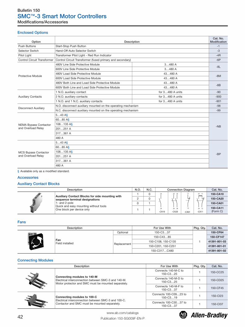
Bulletin 150
SMC™-3 Smart Motor Controllers
42www.ab.com/catalogs
Publication 150-SG009F-EN-P
Accessories
Auxiliary Contact Blocks
Description N.O. N.C. Connection Diagram Cat. No.
Auxiliary Contact Blocks for side mounting withsequence terminal designations1- and 2-poleQuick and easy mounting without toolsOne block per device only
1 0 150-CA10
2 0 150-CA20
0 1 150-CA01
1 1 150-CA11(Form C)
Fans
Description For Use With Pkg. Qty. Cat. No.
FanField installed
Optional 150-C3…37
1
150-CF64
Replacement
150-C43…85 150-CF147
150-C108, 150-C135 41391-801-03
150-C201, 150-C251 41391-801-01
150-C317…C480 41391-801-02
Connecting Modules
Description For Use With Pkg. Qty. Cat. No.
Connecting modules to 140-MElectrical interconnection between SMC-3 and 140-M.Motor protector and SMC must be mounted separately.
Connects 140-M-C to150-C3…25 1 150-CC25
Connects 140-M-D to150-C3…25 1 150-CD25
Connects 140-M-F to150-C3…37 1 150-CF45
Connecting modules to 100-CElectrical interconnection between SMC-3 and 100-C.Contactor and SMC must be mounted separately.
Connects 100-C09…23 to150-C3…19 1 150-CI23
Connects 100-C30…37 to150-C3…37 1 150-CI37
Modifications/Accessories
Enclosed Options
Option DescriptionCat. No.
Modification
Push Buttons Start-Stop Push Button -1
Selector Switch Hand-Off-Auto Selector Switch -3
Pilot Light Transformer Pilot Light - Red Run Indicator -4R
Control Circuit Transformer Control Circuit Transformer (fused primary and secondary) -6P
Protective Module
480V Line Side Protective Module 3…480 A-8L
600V Line Side Protective Module 3…480 A
480V Load Side Protective Module 43…480 A-8M
600V Load Side Protective Module 43…480 A
480V Both Line and Load Side Protective Module 43…480 A-8B
600V Both Line and Load Side Protective Module 43…480 A
Auxiliary Contacts
1 N.O. auxiliary contact for 3…480 A units -90
2 N.O. auxiliary contacts for 3…480 A units -900
1 N.O. and 1 N.C. auxiliary contacts for 3…480 A units -901
Disconnect AuxiliaryN.O. disconnect auxiliary mounted on the operating mechanism -98
N.C. disconnect auxiliary mounted on the operating mechanism -99
NEMA Bypass Contactorand Overload Relay
5…43 A§
-NB
60…85 A§
108…135 A§
201…251 A
317…361 A
480 A
MCS Bypass Contactorand Overload Relay
5…43 A§
-BP
60…85 A§
108…135 A§
201…251 A
317…361 A
480 A
§ Available only as a modified standard.

Bulletin 150
SMC™-3 Smart Motor Controllers
43www.ab.com/catalogs
Publication 150-SG009F-EN-P
Protective ModulesProtective modules must not be placed on the load side of a device when using an inside-the-delta connection.
Description For Use With Pkg. Qty. Cat. No.
480V Protective Module
150-C3…37NB 1 150-C84
150-C43…85NB (line and/or load) 1 150-C84P
150-C108…480NB (line and/or load) 1 150-F84L
600V Protective Module
150-C3…37NC 1 150-C86
150-C43…85NC (line and/or load) 1 150-C86P
150-C108…480NC (line and/or load) 1 150-F86L
IEC Terminal Covers
Description For Use With Pkg. Qty. Cat. No.
Terminal CoverIEC line or load terminal covers for 108…480 A devices.
Dead front protection
150-C108…-C135 1 150-TC1
150-C201…-C251 1 150-TC2
150-C317…-C480 1 150-TC3
Terminal Lug Kits (108…480 A)
CurrentRating [A] ‡ Wire Size
Total No. of Line ControllerTerminal Lugs
Possible Each Side
Pkg. Qty. Cat. No.Line Side Load Side
108…135Δ #6…250 MCM AWG16 mm2…120 mm2
3 3
3
199-LF1201…251Δ 6 6
317…480Δ #4…500 MCM AWG25 mm2…240 mm2 6 6 199-LG1
Line and Load terminals are provided as standard on enclosed SMCs.‡ 1…85 A units have box lugs standard. No additional lugs are required.Δ When a multi-conductor lug is required, refer to the Instruction Sheet for appropriate lug catalog number.
Marking Tags and Covers
Description For Use With Pkg. Qty. Cat. No.
Marking Tag Sheet160 perforated paper labels each, 6 x 17 mm, to be usedwith a transparent cover
150-C, 150-D 10 100-FMP
Transparent CoverTo be used with marking tag sheets 150-C, 150-D 100 100-FMC
Remote Reset Solenoid
Description For Use With Pkg. Qty. Cat. No.
Remote Reset Solenoid for remote reset of electronicoverload 193-T all, 150-C 1 193-ER1⊗
⊗ Voltage Suffix Code
Available Coil Voltages 12…600V 50 Hz/12…600V 60 HzStandard Coil Voltages
Voltage 24 48 110 115 120 220 240
50 Hz J — D — — A —
60 Hz J — — — D — A
DC Z24 Z48 — Z01 — — —
Surcharge for special voltages up to 20 pcs. (no surcharge for quantities greater than 20 pcs.)
Accessories

Bulletin 150
SMC™-3 Smart Motor Controllers
44www.ab.com/catalogs
Publication 150-SG009F-EN-P
Two-Wire ConfigurationIEC
SMC-3 Control Terminals
E-Stop
H4H2
H1H3
X1 X2
Trans.
Ground
A2A1 IN1 IN2
OVLD/Fault AUX #1
97 98 13 14
-TC
-SB
Two-WireDevice
-E1
-E1(PowerConnections)
NEMA
Three-Wire Configuration
IEC
SMC-3 Control Terminals
E-Stop
H4H2
H1H3
X1 X2
Trans.
Ground
A2A1 IN1 IN2
OVLD/Fault AUX #1
97 98 13 14
-TC
-SB1
-E1
-E1(PowerConnections)
Stop Option-SB2
Start-SB3
NEMA
Typical Wiring Diagrams

Bulletin 150
SMC™-3 Smart Motor Controllers
45www.ab.com/catalogs
Publication 150-SG009F-EN-P
Isolation Contactor ConfigurationIEC
SMC-3 Control Terminals
H4H2
H1H3
X1 X2Trans.
Ground
A2A1 IN1 IN2
OVLD/Fault AUX #1
97 98 13 14
-E1
-TC
-SB1E-Stop
-KM
-E1(PowerConnections)
-SB3Start
-SB2Stop Option
-KM
NEMA
Motor
L3/5
T1/2L1/1
T2/4
T3/6
L2/3
SMC-3(Power connections)
SMC-3 Control Terminals
E-StopH4H2
H1H3
X1 X2Trans. Ground
A2A1 IN1 IN2
OVLD/Fault AUX #1
97 98 13 14
IC
ICStop Option Start
Reversing ConfigurationNote: Minimum Off time equals 1.0 s.
IEC
SMC-3 Control Terminals
H4H2
H1H3
X1 X2
Trans.
Ground
A2A1 IN1 IN2
OVLD/Fault AUX #1
97 98 13 14
-E1(PowerConnections)
-TC
-KM2-KM1
-SBE-Stop
-KM2-KM1
-KM2 -KM1 -KM2 -KM1
-SA
FOR REVOFF
NEMA
Motor
L3/5
T1/2L1/1
T2/4
T3/6
L2/3
SMC-3(Power connections)
SMC-3 Control Terminals
E-Stop H4H2
H1H3
X1 X2
Trans. Ground
A2A1 IN1 IN2
OVLD/Fault AUX #1
97 98 13 14
F
FR
R
F
R
FOR REVOFF
F
R
Typical Wiring Diagrams
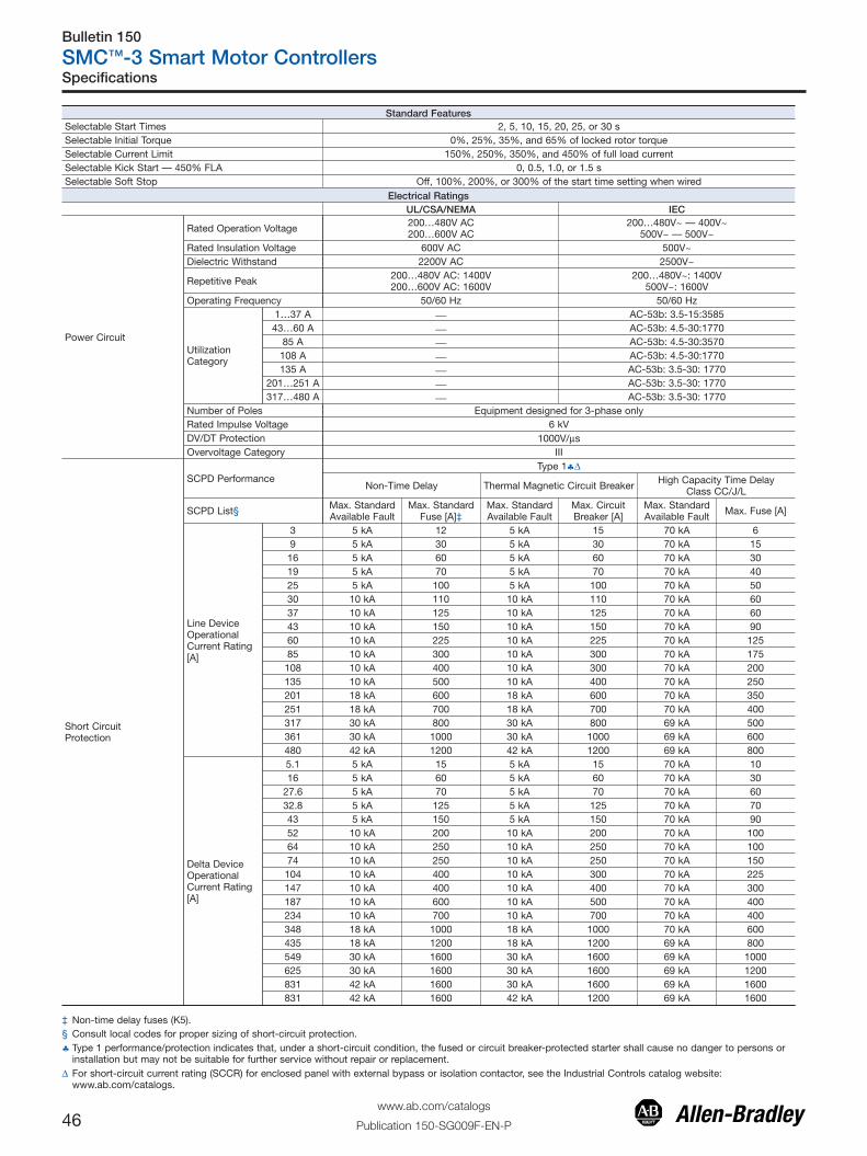
Bulletin 150
SMC™-3 Smart Motor Controllers
46www.ab.com/catalogs
Publication 150-SG009F-EN-P
Standard FeaturesSelectable Start Times 2, 5, 10, 15, 20, 25, or 30 sSelectable Initial Torque 0%, 25%, 35%, and 65% of locked rotor torqueSelectable Current Limit 150%, 250%, 350%, and 450% of full load currentSelectable Kick Start — 450% FLA 0, 0.5, 1.0, or 1.5 sSelectable Soft Stop Off, 100%, 200%, or 300% of the start time setting when wired
Electrical RatingsUL/CSA/NEMA IEC
Power Circuit
Rated Operation Voltage 200…480V AC200…600V AC
200…480V~ — 400V~500V~ — 500V~
Rated Insulation Voltage 600V AC 500V~Dielectric Withstand 2200V AC 2500V~
Repetitive Peak 200…480V AC: 1400V200…600V AC: 1600V
200…480V~: 1400V500V~: 1600V
Operating Frequency 50/60 Hz 50/60 Hz
UtilizationCategory
1…37 A ⎯ AC-53b: 3.5-15:358543…60 A ⎯ AC-53b: 4.5-30:1770
85 A ⎯ AC-53b: 4.5-30:3570108 A ⎯ AC-53b: 4.5-30:1770135 A ⎯ AC-53b: 3.5-30: 1770
201…251 A ⎯ AC-53b: 3.5-30: 1770317…480 A ⎯ AC-53b: 3.5-30: 1770
Number of Poles Equipment designed for 3-phase onlyRated Impulse Voltage 6 kVDV/DT Protection 1000V/μsOvervoltage Category III
Short CircuitProtection
SCPD PerformanceType 1♣Δ
Non-Time Delay Thermal Magnetic Circuit Breaker High Capacity Time DelayClass CC/J/L
SCPD List§ Max. StandardAvailable Fault
Max. StandardFuse [A]‡
Max. StandardAvailable Fault
Max. CircuitBreaker [A]
Max. StandardAvailable Fault Max. Fuse [A]
Line DeviceOperationalCurrent Rating[A]
3 5 kA 12 5 kA 15 70 kA 69 5 kA 30 5 kA 30 70 kA 1516 5 kA 60 5 kA 60 70 kA 3019 5 kA 70 5 kA 70 70 kA 4025 5 kA 100 5 kA 100 70 kA 5030 10 kA 110 10 kA 110 70 kA 6037 10 kA 125 10 kA 125 70 kA 6043 10 kA 150 10 kA 150 70 kA 9060 10 kA 225 10 kA 225 70 kA 12585 10 kA 300 10 kA 300 70 kA 175108 10 kA 400 10 kA 300 70 kA 200135 10 kA 500 10 kA 400 70 kA 250201 18 kA 600 18 kA 600 70 kA 350251 18 kA 700 18 kA 700 70 kA 400317 30 kA 800 30 kA 800 69 kA 500361 30 kA 1000 30 kA 1000 69 kA 600480 42 kA 1200 42 kA 1200 69 kA 800
Delta DeviceOperationalCurrent Rating[A]
5.1 5 kA 15 5 kA 15 70 kA 1016 5 kA 60 5 kA 60 70 kA 30
27.6 5 kA 70 5 kA 70 70 kA 6032.8 5 kA 125 5 kA 125 70 kA 7043 5 kA 150 5 kA 150 70 kA 9052 10 kA 200 10 kA 200 70 kA 10064 10 kA 250 10 kA 250 70 kA 10074 10 kA 250 10 kA 250 70 kA 150104 10 kA 400 10 kA 300 70 kA 225147 10 kA 400 10 kA 400 70 kA 300187 10 kA 600 10 kA 500 70 kA 400234 10 kA 700 10 kA 700 70 kA 400348 18 kA 1000 18 kA 1000 70 kA 600435 18 kA 1200 18 kA 1200 69 kA 800549 30 kA 1600 30 kA 1600 69 kA 1000625 30 kA 1600 30 kA 1600 69 kA 1200831 42 kA 1600 30 kA 1600 69 kA 1600831 42 kA 1600 42 kA 1200 69 kA 1600
‡ Non-time delay fuses (K5).§ Consult local codes for proper sizing of short-circuit protection.♣ Type 1 performance/protection indicates that, under a short-circuit condition, the fused or circuit breaker-protected starter shall cause no danger to persons or
installation but may not be suitable for further service without repair or replacement.Δ For short-circuit current rating (SCCR) for enclosed panel with external bypass or isolation contactor, see the Industrial Controls catalog website:
www.ab.com/catalogs.
Specifications

Bulletin 150
SMC™-3 Smart Motor Controllers
47www.ab.com/catalogs
Publication 150-SG009F-EN-P
Electrical RatingsUL/CSA/NEMA IEC
Control Circuit
Rated Operational Voltage (+10%, –15%) 100…240V AC, 24V AC/DC 100…240V~, 24V AC/DCRated Insulation Voltage 250V 250V~Rated Impulse Voltage 2.5 kV 4 kVDielectric Withstand 1500V AC 2000V~Overvoltage Category II III�Operating Frequency 50/60 Hz 50/60 HzInput onstate voltage minimum, during start (IN1, IN2) 85V AC, 19.2V DC / 19.2V ACInput onstate current (IN1, IN2) 9.8 mA @120V AC/19.6 mA @ 240V AC, 7.3 mA @ 24V AC/DCInput offstate voltage maximum (IN1, IN2) 40V AC, 17V DC / 12V ACInput offstate current @ input offstate voltage (IN1, IN2) <10 mA, <12 mA
Control Power with Fan, during start
3…37 A 215 mA @ 120V AC / 180 mA @ 240V AC, 800 mA @ 24V DC / 660 mA @24V AC
43…85 A 200 mA @ 120V AC / 100 mA @ 240V AC, 700 mA @ 24V AC/DCFan Power Control Power
108…135 A 20VA200 mA @ 120V AC / 120 mA @ 240V AC, 600 mA @ 24V
AC/DC201…251 A 40VA317…480 A 60VA
Control Power without Fan, during start 3…37 A 205 mA @ 120V AC / 145 mA @ 240V AC, 705 mA @ 24V DC / 580 mA @24V AC
Steady State Heat Dissipation and Overload Current Range
Controller Rating [A] Steady State Heat Dissipation [W] Overload Current Range [A]3 11 1…39 12 3…9
16 14 5.3…1619 15 6.3…1925 17 9.2…27.730 19 10…3037 24 12.3…3743 34 14.3…4360 50 20…6085 82 28.3…85
108 62 27…108135 75 34…135201 129 67…201251 147 84…251317 174 106…317361 194 120…361480 239 160…480
Auxiliary ContactsUL/CSA/NEMA IEC
Rated Operational Voltage 250V AC/30V DC 250V~/30V DCRated Insulation Voltage 250V 250V~Rated Impulse Voltage 2.5 kV 4 kVDielectric Withstand 1500V AC 2000V~Overvoltage Category II III�Operating Frequency 50/60 Hz 50/60 HzUtilization Category D300/D300 AC-15/DC
TB-97, -98 (OVLD/Fault)
Type of Control Circuit Electromagnetic relayNumber of Contacts 1Type of Contacts Normally Open (N.O.)Type of Current AC/DCRated Operational Current (max.) 0.6 A @ 120V~ and 0.3 A @ 240V~Conventional Thermal Current Ith 1 AMake/Break VA 432/72
TB-13, -14 Aux 1(Normal/Up-to-Speed)
Type of Control Circuit Electromagnetic relayNumber of Contacts 1Type of Contacts Normally Open (N.O.)Type of Current AC/DCRated Operational Current (max.) 0.6 A @ 120V~ and 0.3 A @ 240V~Conventional Thermal Current Ith 1 AMake/Break VA 432/72
�Overvoltage category II, when either control or auxiliary circuit is wired to a SELV or PELV circuit.
Specifications

Bulletin 150
SMC™-3 Smart Motor Controllers
48www.ab.com/catalogs
Publication 150-SG009F-EN-P
Electrical RatingsSide-Mount Auxiliary Contacts
UL/CSA/NEMA IECRated Operational Voltage 250V AC/30V DC 250V AC/30V DCRated Insulation Voltage 250V 250V ACRated Impulse Voltage 2.5 kV 4 kVDielectric Withstand 1500V AC 2000V ACOvervoltage Category II III�Operating Frequency 50/60 Hz 50/60 Hz
TB-23, -24(Normal/Up-to-Speed)TB-33, -34(Normal/Up-to-Speed)
Utilization Category C300/R150 AC-15/DC-13Type of Control Circuit Electromagnetic relayNumber of Contacts 1Type of Contacts Normally Open (N.O.)Type of Current AC/DCRated Operational Current (max.) 1.5 A @ 120V AC, 0.75A @ 240V AC, 1.17 A @ 24V DCConventional Thermal Current Ith 2.5 AMake/Break VA 1800/180V AC, 28V DC (resistive)
TB-11, -12 (Normal/Up-to-Speed)
Type of Control Circuit B300/R300 AC-15/DC-13Type of Control Circuit Electromagnetic relayNumber of Contacts 1Type of Contacts Normally Closed (N.C.)Type of Current AC/DCRated Operational Current (max.) 3 A @ 120V AC, 1.5A @ 240V AC, 1.17 A @ 24V DCConventional Thermal Current Ith 5 AMake/Break VA 3600/360VA, 28VA (DC resistive)
�Overvoltage category II, when either control or auxiliary circuit is wired to a SELV or PELV circuit.
Environmental
Operating Temperature Range -5…+50 °C (23…122 °F) (open)-5…+40 °C (23…104 °F) (enclosed)
Storage and Transportation Temperature Range -25…+85 °C (-13…+185 °F)Altitude 2000 m (6560 ft)Humidity 5…95% (non-condensing)Pollution Degree 2Type of Protection IP2X
Mechanical Ratings
Resistance to VibrationOperational 1.0 G Peak, 0.15 mm (0.006 in.) displacementNon-Operational 2.5 G Peak, 0.38 mm (0.015 in.) displacement
Resistance to ShockOperational 15 GNon-Operational 30 G
Line Power Terminals Cable SizeTightening Torque
3…37 A 2.5…25 mm2 (14…4 AWG)2.3…2.8 N•m (20…25 in•lbs)
43…85 A 2.5…95 mm2 (14…3/0 AWG)11.3…12.4 N•m (100…110 in•lbs)
108…135 A 23 N•m (200 in•lbs)201…251 A Two M10 x 1.5 diameter holes per power pole317…480 A Two M12 x 1.75 diameter holes per power pole
Load Power Terminals Cable SizeTightening Torque
3…37 A 2.5…16 mm2 (14…6 AWG)2.3…2.5 N•m (20…22.5 in•lbs)
43…85 A 2.5…50 mm2 (14…1 AWG)11.3…12.4 N•m (100…110 in•lbs)
108…135 A 23 N•m (200 in•lbs)201…251 A Two M10 x 1.5 diameter holes per power pole317…480 A Two M12 x 1.75 diameter holes per power pole
Control Terminals Cable SizeTightening Torque All 0.2…2.5 mm2 (24…14 AWG)
0.5…0.9 N•m (4.4…8.0 in•lbs)Other
UL/CSA/NEMA IEC
EMC Emission LevelsConducted Radio Frequency Emissions ⎯ Class ARadiated Emissions ⎯ Class A
EMC Immunity Levels
Electrostatic Discharge 4 kV Contact and 8 kVAir Discharge 8 kV Air Discharge
Radio Frequency Electromagnetic Field ⎯ Per EN/IEC 60947-4-2Fast Transient ⎯ Per EN/IEC 60947-4-2Surge Transient ⎯ Per EN/IEC 60947-4-2
Specifications

Bulletin 150
SMC™-3 Smart Motor Controllers
49www.ab.com/catalogs
Publication 150-SG009F-EN-P
t (se
c)
Current
Cold Trip
Hot Trip
Trip Class 15
t (se
c)
Current
Cold Trip
Hot Trip
Trip Class 20
t (se
c)
Current
Cold Trip
Hot Trip
Starts per Hour Curves
(3…37 A)
Star
ts/H
our
Current [A]
SMC-3 Starts per hour (3…37 A)40 °C, 100% Duty Cycle, 10 s, 350% No Fan
(3…37 A)
Star
ts/H
our
Current [A]
SMC-3 Starts per hour (3…37 A)40 °C, 100% Duty Cycle, 10 s, 350% with Fan
Current (amps)
Starts
SMC-3 Starts per hour (43…85 A) 40C,100% Duty Cycle, 20 sec, 350% (with standard fan)
0
20
40
60
80
100
120
140
160
180
200
0 10 20 30 40 50 60 70 80 90
150-C43
150-C60
150-C85
SMC-3 Overload Trip CurvesTrip Class 10
SMC-3 Starts per hour (108…135 A)40C, 100% Duty Cycle, 20 sec, 350% (with standard fan)
0
20
40
60
80
100
120
140
160
180
200
0 10 20 30 40 50 60 70 80 90 100 110 120 130 140 150
Current (amps)
Star
t/Hou
r
150-C108
150-F135
51
56
511
561
512
562
513
06406306206106
)spmA( tnerruC
Star
ts /
ho
ur
-051152C,102C
-051163C,713C
084C-051
SMC-3 Starts per hour (201…480 A)40C, 100% Duty Cycle, 20 sec, 350% (with standard fan)
Specifications

Bulletin 150
SMC™-3 Smart Motor Controllers
50www.ab.com/catalogs
Publication 150-SG009F-EN-P
Approximate Dimensions
Dimensions in millimeters (inches). Dimensions are not intended to be used for manufacturing purposes. All dimensions are subject tochange.
Open Type
ControllerRating [A] A B C D E F G
MountingHole Size
Weightkg (lbs)
1…37 44.8 (1-49/64) 139.7 (5-1/2) 100 (4-21/64) 35 (1-3/8) 132 (5-13/64) 46.4 (1.81) 2 (1/16) 4.6 (0.18) 0.86 (1.9)
43…85 72 (2.83) 206 (8.11) 130 (5.12) 55 (2.17) 198 (7.8) 102 (4.02) 2 (1/16) 5.3 (0.21) 2.25 (5.0)
108…135 196.4 (7.74) 443.7 (17.47) 205.2 (8.08) 166.6 (6.56) 367 (14.45) ⎯ ⎯ 7.5 (0.295) 15 (33)
201…251 225 (8.86) 560 (22.05) 265.3 (10.45) 150 (5.91) 504.1 (19.85) ⎯ ⎯ 11.5 (0.45) 30.4 (67)
317…480 290 (11.42) 600 (23.62) 298 (11.73) 200 (7.87) 539.2 (21.23) ⎯ ⎯ 11.5 (0.45) 45.8 (101)
Minimum Enclosure Size
ControllerRating [A] B Height A Width C Depth Fan Requirements
1…37 A 305 (12) 224 (9) 152 (6) none
43…85 A 406 (16) 305 (12) 203 (8) none
108…135 A 762 (30) 610 (24) 305 (12) none
201…251 A 965 (38) 762 (30) 356 (14) none
317…480 A 1295 (51) 914 (36) 356 (14) none

Bulletin 150
SMC™-3 Smart Motor Controllers
51www.ab.com/catalogs
Publication 150-SG009F-EN-P
Enclosed Type Line-Connected ControllersA
B
D
E
F
C
Figure 1 — Wall-Mount
B
ACD E
F
Figure 2 — Wall-Mount
B
A
C
Figure 3 — Floor-Mount
B
A
CLIFTING ANGLE
Figure 4 — Floor-Mount
Approximate Dimensions
ControllerRating [A] Bulletin With Option
DimensionFigure No.
Dimensions in inches (mm)
A (Width) B (Height) C (Depth) D (Mtg. Dim.) E (Mtg. Dim.) F (Mtg. Dim.)
SMC-3 Non-Combination Controller
3…37 150—
18 (203) 12 (305) 6 (152) 2.44 (62) 10.43 (265) 3.0 (76)
6P 12 (305) 12 (305) 6 (152) 2.41 (61) 10.43 (265) 7.0 (178)
43…85 150—
18 (203) 14 (356) 8 (203) 2.44 (62) 12.40 (315) 3.0 (76)
6P 16 (406) 14 (356) 8 (203) 4.38 (111) 12.40 (315) 7.0 (178)
108…135 150 Any 1 24 (610) 30 (762) 12 (305) 0.75 (19) 28.5 (724) 22.5 (572)
201…251150 —
130 (762) 38 (965) 14 (356) 0.75 (19) 36.5 (927) 28.5 (724)
150, 150B BP,NB,NI,6P 36 (914) 51 (1295) 14 (356) 0.75 (19) 49.5 (1257) 34.5 (876)
317…361
150 Any
1
36 (914) 51 (1295) 14 (356) 0.75 (19) 49.5 (1257) 34.5 (876)
150B
— 36 (914) 51 (1295) 14 (356) 0.75 (19) 49.5 (1257) 34.5 (876)
NI, 6P 36 (914) 51 (1295) 14 (356) 0.75 (19) 49.5 (1257) 34.5 (876)
BP,NI, 6P 36 (914) 60 (1524) 14 (356) 0.75 (19) 58.5 (1486) 34.5 (876)
480150 —
136 (914) 51 (1295) 14 (356) 0.75 (19) 49.5 (1257) 34.5 (876)
150, 150B BP,NB,NI,6P 36 (914) 60 (1524) 14 (356) 0.75 (19) 58.5 (1486) 34.5 (876)

Bulletin 150
SMC™-3 Smart Motor Controllers
52www.ab.com/catalogs
Publication 150-SG009F-EN-P
Approximate Dimensions
ControllerRating [A] Bulletin With Option
DimensionFigure No.
Dimensions in inches (mm)
A (Width) B (Height) C (Depth) D (Mtg. Dim.) E (Mtg. Dim.) F (Mtg. Dim.)
SMC-3 Combination Controller
3…37 152H,153H Any 1 16 (406) 14 (356) 8 (203) 4.38 (111) 12.40 (315) 7.0 (178)
43152H Any 1 16 (406) 14 (356) 8 (203) 4.38 (111) 12.40 (315) 7.0 (178)
153H Any 1 16 (406) 24 (610) 10 (254) 0.75 (19) 22.5 (572) 14.5 (368)
60152H, 153H Any 1 16 (406) 24 (610) 9 (229) 0.75 (19) 22.5 (572) 14.5 (368)
152H Any 1 24 (610) 30 (762) 12 (305) 0.75 (19) 28.5 (724) 22.5 (572)
85152H
Any 1� 16 (406) 24 (610) 9 (229) 0.75 (19) 22.5 (572) 14.5 (368)
Any 1‡ 24 (610) 30 (762) 12 (305) 0.75 (19) 28.5 (724) 22.5 (572)
153H Any 1 16 (406) 24 (610) 9 (229) 0.75 (19) 22.5 (572) 14.5 (368)
108 152H,153H Any 1 30 (762) 38 (965) 14 (356) 0.75 (19) 36.5 (927) 28.5 (724)
135 152H,153H Any 1 30 (762) 38 (965) 14 (356) 0.75 (19) 36.5 (927) 28.5 (724)
201152H,153H — 1 30 (762) 38 (965) 14 (356) 0.75 (19) 36.5 (927) 28.5 (724)
152H,152B,153H,153B Any 1 36 (914) 51 (1295) 14 (356) 0.75 (19) 49.5 (1257) 34.5 (876)
251152H,153H — 1 30 (762) 38 (965) 14 (356) 0.75 (19) 36.5 (927) 28.5 (724)
152H,152B,153H,153B Any 1 36 (914) 51 (1295) 14 (356) 0.75 (19) 49.5 (1257) 34.5 (876)
317
153H— 1 36 (914) 51 (1295) 14 (356) 0.75 (19) 49.5 (1257) 34.5 (876)
BP,NB 1 36 (914) 60 (1524) 14 (356) 0.75 (19) 58.5 (1486) 34.5 (876)
153B — 1 36 (914) 60 (1524) 14 (356) 0.75 (19) 58.5 (1486) 34.5 (876)
152H,152B — 2 38 (965) 60 (1524) 17 (431) 33.88 (861) 1.75 (45) 61.69 (1567)
152H BP 2 38 (965) 60 (1524) 17 (431) 33.88 (861) 1.75 (45) 61.69 (1567)
152H,152B,153H,153B NB,NI 3 40 (1016) 84 (2134) 18 (457) — — —
361
153H— 1 36 (914) 51 (1295) 14 (356) 0.75 (19) 49.5 (1257) 34.5 (876)
BP,NB 1 36 (914) 60 (1524) 14 (356) 0.75 (19) 58.5 (1486) 34.5 (876)
153B — 1 36 (914) 60 (1524) 14 (356) 0.75 (19) 58.5 (1486) 34.5 (876)
152H,152B — 2 38 (965) 60 (1524) 17 (431) 33.88 (861) 1.75 (45) 61.69 (1567)
152H BP 2 38 (965) 60 (1524) 17 (431) 33.88 (861) 1.75 (45) 61.69 (1567)
152H,152B,153H,153B NB,NI 3 40 (1016) 84 (2134) 18 (457) — — —
480
153H— 1 36 (914) 51 (1295) 14 (356) 0.75 (19) 49.5 (1257) 34.5 (876)
BP 3♣ 40 (1016) 84 (2134) 18 (457) — — —
152H,153B Any 3 40 (1016) 84 (2134) 18 (457) — — —
152H — 4♣ 20 (508) 91.5 (2324) 20 (508) — — —
152H,152B BP,NB 4♣ 35 (889) 91.5 (2324) 20 (508) — — —
�Rating 20 Hp @208V, 25 Hp @240V, 50 Hp @ 480V, 60 Hp @ 600V‡ Rating 25 Hp @208V, 30 Hp @240V, 60 Hp @ 480V, 75 Hp @ 600V♣ 200 Hp @ 240V AC, 400 Hp @480V, 500 Hp @ 600V

Bulletin 150
SMC™-3 Smart Motor Controllers
53www.ab.com/catalogs
Publication 150-SG009F-EN-P

SMC, Allen-Bradley, Rockwell Software, Rockwell Automation, and LISTEN. THINK. SOLVE are trademarks of Rockwell Automation, Inc.
Trademarks not belonging to Rockwell Automation are property of their respective companies.
Publication 150-SG009F-EN-P March 2013Supersedes Publication 150-SG009E-EN-P - October 2011 Copyright © 2013 Rockwell Automation, Inc. All rights reserved. Printed in the U.S.A.