Embed Size (px)
Citation preview

User Guide
SMC D3GNV/D3GNV3 Wireless Gateway
FastFind Links
Getting to Know the Gateway
Installing the Gateway
Compliance Statements
P a g e | 2
SMC Networks 20 Mason
Irvine, CA. 92618 U.S.A.
Copyright © 2013 SMC Networks
All Rights Reserved
Information furnished by SMC Networks, Inc. (SMC) is believed to be accurate and reliable. However, no responsibility is assumed by SMC for its use, or for any infringements of patents or other rights of third parties which may result from its use. No license is granted by implication or otherwise under any patent or patent rights of SMC. SMC reserves the right to change specifications at any time without notice
No part of this publication may be reproduced or transmitted in any form or by any means, electronic or mechanical, including photocopying and recording, or stored in a database or retrieval system for any purpose without the express written permission of SMC.
Microsoft and Windows are registered trademarks of Microsoft Corporation. Apple and Macintosh are registered trademarks of Apple, Inc. All other brands, product names, trademarks, or service marks are property of their respective owners.
This product (Model: SMCD3GNV and SMCD3GNV3) includes software code developed by third parties, including software code subject to the GNU General Public License (“GPL”) or GNU Lesser General Public License (LGPL”). As applicable, the terms of the GPL and LGPL, and information on obtaining access to the GPL code and LGPL used in this product, are available to you at http://gpl.smc.com/. The GPL code and LGPL code used in this product is distributed WITHOUT ANY WARRANTY and is subject to the copyrights of one or more authors. For details, see the GPL Code and LGPL Code for this product and the terms of the GPL and LGPL.
SMCD3GNV and SMCD3GNV3 User Guide
Issued: April 19, 2013
SMCD3GNV and SMCD3GNV3 User Guide
P a g e | 3
1 Getting to Know the Gateway
Before you install your SMCD3GNV Wireless Cable Modem Gateway, check the package
contents and become familiar with the Gateway’s front and back panels.
The topics covered in this chapter are:
Unpacking Package Contents (page 4)
System Requirements (page 3)
Front Panel (page 5)
Rear Panel (page 6)
Top Panel (page 7)
Bottom Panel (page 7)
Using the Reset Button (page 8)

SMCD3GNV and SMCD3GNV3 User Guide
P a g e | 4
Unpacking Package Contents
Unpack the items in your SMCD3GNV Wireless Cables Modem Gateway contents and
confirm that no items are missing or damaged. Your package should include:
One SMCD3GNV Wireless Cable Modem Gateway
One standard power cord
GPL / GNU public license statement
If any items are missing or damaged, please contact your cable service provider. Keep the
carton, including the original packing material, in case you need to store the product or
return it.
System Requirements
To complete your installation, you will need the following items:
Provisioned Internet access on a cable network that supports cable modem service.
A computer with a wired network adapter with TCP/IP installed.
A Java-enabled Web browser, such as Microsoft Internet Explorer 5.5 or above.
Microsoft® Windows® 2000 or higher for USB driver support.
An analog telephone and two RJ-11 cables if you want to connect the Gateway to an
analog telephone and PSTN telephone line.
SMCD3GNV and SMCD3GNV3 User Guide
P a g e | 5
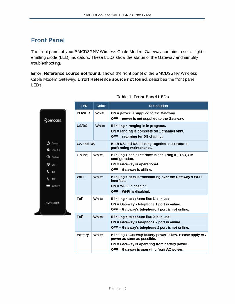
Front Panel
The front panel of your SMCD3GNV Wireless Cable Modem Gateway contains a set of light-
emitting diode (LED) indicators. These LEDs show the status of the Gateway and simplify
troubleshooting.
Error! Reference source not found. shows the front panel of the SMCD3GNV Wireless
Cable Modem Gateway. Error! Reference source not found. describes the front panel
LEDs.
Table 1. Front Panel LEDs
LED Color Description
POWER White ON = power is supplied to the Gateway.
OFF = power is not supplied to the Gateway.
US/DS White Blinking = ranging is in progress.
ON = ranging is complete on 1 channel only.
OFF = scanning for DS channel.
US and DS Both US and DS blinking together = operator is performing maintenance.
Online White Blinking = cable interface is acquiring IP, ToD, CM configuration.
ON = Gateway is operational.
OFF = Gateway is offline.
WiFi White Blinking = data is transmitting over the Gateway’s Wi-Fi interface.
ON = Wi-Fi is enabled.
OFF = Wi-Fi is disabled.
Tel1 White Blinking = telephone line 1 is in use.
ON = Gateway’s telephone 1 port is online.
OFF = Gateway’s telephone 1 port is not online.
Tel2 White Blinking = telephone line 2 is in use.
ON = Gateway’s telephone 2 port is online.
OFF = Gateway’s telephone 2 port is not online.
Battery White Blinking = Gateway battery power is low. Please apply AC power as soon as possible.
ON = Gateway is operating from battery power.
OFF = Gateway is operating from AC power.
SMCD3GNV and SMCD3GNV3 User Guide
P a g e | 6
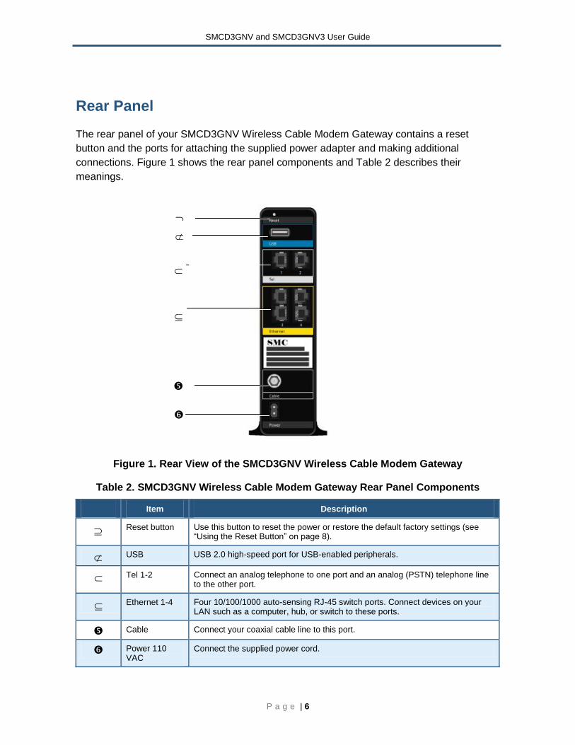
Rear Panel
The rear panel of your SMCD3GNV Wireless Cable Modem Gateway contains a reset
button and the ports for attaching the supplied power adapter and making additional
connections. Figure 1 shows the rear panel components and Table 2 describes their
meanings.
Figure 1. Rear View of the SMCD3GNV Wireless Cable Modem Gateway
Table 2. SMCD3GNV Wireless Cable Modem Gateway Rear Panel Components
Item Description
Reset button Use this button to reset the power or restore the default factory settings (see “Using the Reset Button” on page 8).
USB USB 2.0 high-speed port for USB-enabled peripherals.
Tel 1-2 Connect an analog telephone to one port and an analog (PSTN) telephone line to the other port.
Ethernet 1-4 Four 10/100/1000 auto-sensing RJ-45 switch ports. Connect devices on your LAN such as a computer, hub, or switch to these ports.
Cable Connect your coaxial cable line to this port.
Power 110 VAC
Connect the supplied power cord.
SMCD3GNV and SMCD3GNV3 User Guide
P a g e | 7
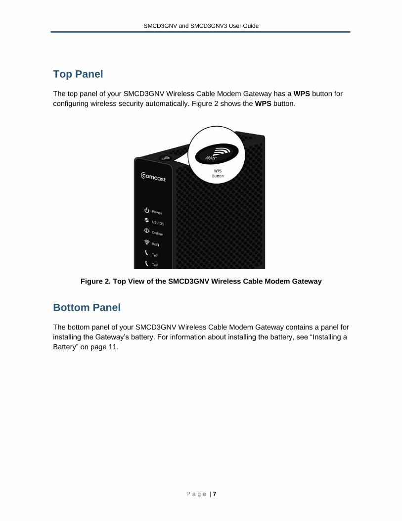
Top Panel
The top panel of your SMCD3GNV Wireless Cable Modem Gateway has a WPS button for
configuring wireless security automatically. Figure 2 shows the WPS button.
Figure 2. Top View of the SMCD3GNV Wireless Cable Modem Gateway
Bottom Panel
The bottom panel of your SMCD3GNV Wireless Cable Modem Gateway contains a panel for
installing the Gateway’s battery. For information about installing the battery, see “Installing a
Battery” on page 11.
SMCD3GNV and SMCD3GNV3 User Guide
P a g e | 8
Using the Reset Button
Using the reset button on the rear panel (see Figure 1 on page 6), you can perform two
types of reset operations with the Gateway:
Software reset – this reset operation power-cycles the Gateway and retains its current
configuration settings.
Factory default reset – this operation remove all overrides made to the Gateway’s factory
default configuration and returns the Gateway to its original factory default settings.
The number of seconds you press the reset button determines which reset operation is
performed. To protect against accidental resets, the reset button is recessed on the
Gateway rear panel.
To use the reset button to perform a software or factory default reset:
1. Leave power plugged into the Gateway.
2. Find the reset button at the top of the back panel, then use a thin object to press and hold
the reset button as follows:
– To perform a software reset, press the reset button for at least 1 second but not more
than 10 seconds.
– To perform a factory default reset, press the reset button for at least 15 seconds.
3. Release the reset button.
4. Note: If you have performed a software reset you will need to let the unit boot up and run
for at least 2 minutes before you can perform a factory default reset.
SMCD3GNV and SMCD3GNV3 User Guide
P a g e | 9
2 Installing the Gateway
This chapter describes how to install your SMCD3GNV Wireless Cable Modem Gateway.
The topics covered in this chapter are:
Finding a Suitable Location (page 10)
Installing a Battery (page 111)
Connecting to the LAN (page 112)
Connecting the WAN (page 1313)
Powering on the Gateway (page 14)
SMCD3GNV and SMCD3GNV3 User Guide
P a g e | 10
Finding a Suitable Location
Your SMCD3GNV Wireless Cable Modem Gateway can be installed in any location with
access to the cable network. All of the cables connect to the rear panel of the Gateway for
better organization and utility. The LED indicators on the front panel are easily visible to
provide you with information about network activity and status.
For optimum performance, the location you choose should:
Be close to a working AC power outlet when powering the Gateway using AC power.
Allow at least one foot of space around the sides and top of the Gateway to provide
sufficient air flow around the device.
Not expose the Gateway to a dusty or wet environment.
Be an elevated location such as a high shelf, keeping the number of walls and ceilings
between the Gateway and your other devices to a minimum.
Be away from electrical devices that are potential sources of interference, such as ceiling
fans, home security systems, microwaves, or the base for a cordless phone.
Be away from any large metal surfaces, such as a solid metal door or aluminum studs.
Large expanses of other materials such as glass, insulated walls, fish tanks, mirrors,
brick, and concrete can also affect your wireless signal.
SMCD3GNV and SMCD3GNV3 User Guide
P a g e | 11
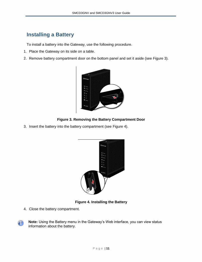
Installing a Battery
To install a battery into the Gateway, use the following procedure.
1. Place the Gateway on its side on a table.
2. Remove battery compartment door on the bottom panel and set it aside (see Figure 3).
Figure 3. Removing the Battery Compartment Door
3. Insert the battery into the battery compartment (see Figure 4).
Figure 4. Installing the Battery
4. Close the battery compartment.
Note: Using the Battery menu in the Gateway’s Web interface, you can view status
information about the battery.
SMCD3GNV and SMCD3GNV3 User Guide
P a g e | 12
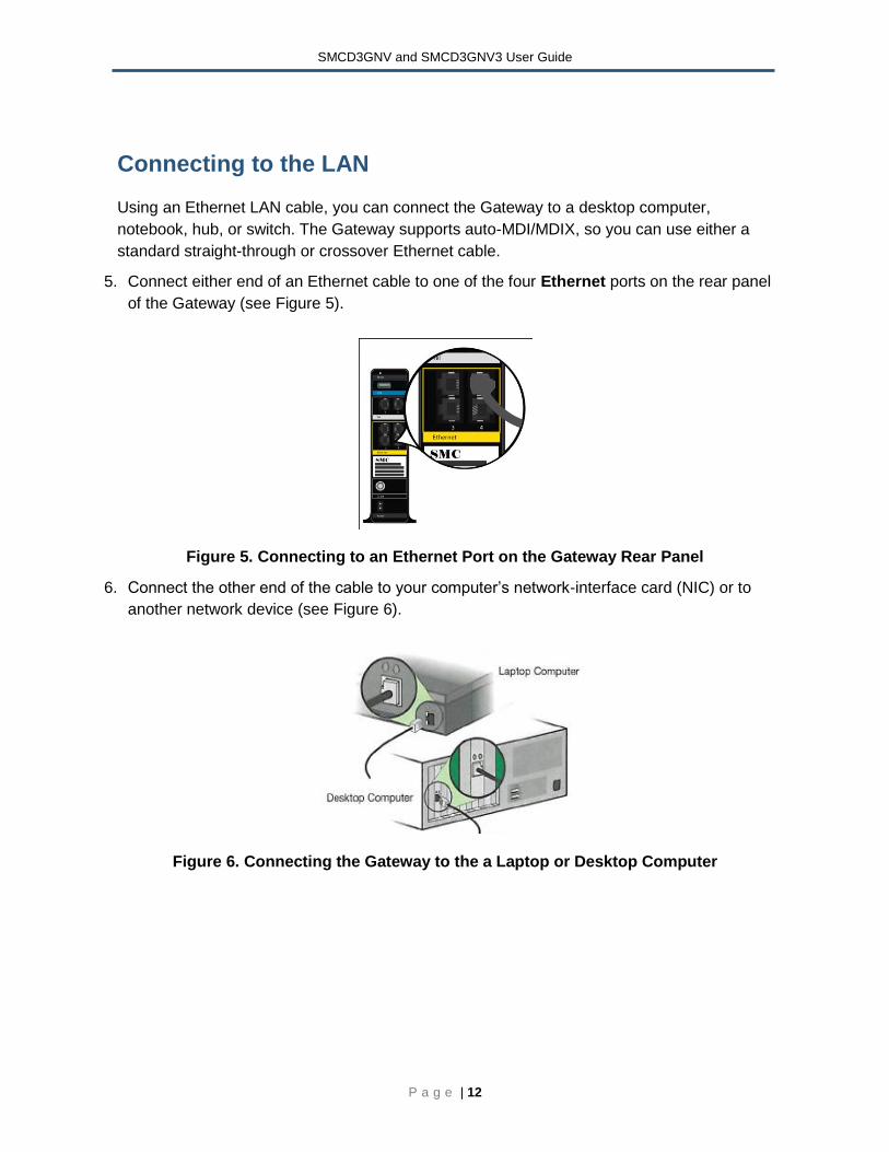
Connecting to the LAN
Using an Ethernet LAN cable, you can connect the Gateway to a desktop computer,
notebook, hub, or switch. The Gateway supports auto-MDI/MDIX, so you can use either a
standard straight-through or crossover Ethernet cable.
5. Connect either end of an Ethernet cable to one of the four Ethernet ports on the rear panel
of the Gateway (see Figure 5).
Figure 5. Connecting to an Ethernet Port on the Gateway Rear Panel
6. Connect the other end of the cable to your computer’s network-interface card (NIC) or to
another network device (see Figure 6).
Figure 6. Connecting the Gateway to the a Laptop or Desktop Computer
SMCD3GNV and SMCD3GNV3 User Guide
P a g e | 13
Connecting the WAN
To connect the Gateway to a Wide Area Network (WAN) interface:
7. Connect a coaxial cable to the port labeled Cable on the rear panel of the Gateway from a
cable port in your home or office (see Figure 1 on page 66). Use only manufactured coaxial
patch cables with F-type connectors at both ends for all connections.
8. Hand-tighten the connectors to secure the connection.
9. If the modem was not installed by your cable provider (ISP) or is replacing another cable
modem, contact your cable operator to register the SMCD3GNV. If the modem is not
registered with your cable operator, it will be unable to connect to the cable network
system.
Connecting to the Public Telephone Network
The rear panel of the Gateway has two RJ-11 telephone-style connectors labeled Tel 1 and
Tel 2. Each of these connectors can provide telephone service to multiple telephones, fax
machines, and analog modems.
The maximum number of telephone devices connected to each RJ-11 port is limited by the
total Ringing Load of the telephone devices that are connected. Many telephone devices are
marked with a Ringer Equivalent Number (REN). Each telephone port on the Gateway can
support up to a 5 REN load. The sum of the REN load on all of the telephone devices
attached to each port must not exceed 5 REN
Before you use the Gateway’s RJ-11 connectors to power the analog devices in your home
or office, disconnect the telephone lines from any other provider at the demarcation point. If
the incoming phone line is connected to another provider, such as an incumbent telephone
company, it can result in potentially harmful voltage to the analog telephone line.
Note: The customer or the customer's wire contractor is responsible for adhering to all local
codes for wiring.
To set up the ability to place calls using a regular analog telephone line (PSTN), perform the
following procedure.
10. Disconnect the phone lines from any other provider at the demarcation point, if appropriate.
11. Connect the RJ-11 cable on an analog device to the Tel 1 connector on the rear panel of
the Gateway.
SMCD3GNV and SMCD3GNV3 User Guide
P a g e | 14
12. Connect the RJ-11 cable on another analog device to the Tel 2 connector on the rear
panel of the Gateway.
Powering on the Gateway
After making your connections, use the following procedure to power on the Gateway:
13. Connect the supplied power cord to the power port on the rear panel of the Gateway (see
Figure 1 on page 6).
14. Connect the other end of the power adapter to a working power outlet. The Gateway
powers on automatically, the POWER LED on the front panel goes ON, and the other front
panel LEDs show the Gateway’s status (see Error! Reference source not found. on
page 5).
WARNING: Only use the power cord supplied with the Gateway. Using a different power cord
can damage the Gateway and void the warranty.
Important Safety Instructions
Read This Before You Begin
When using your equipment, basic safety precautions should always be followed to reduce
the risk of fire, electric shock, and injury to persons, including the following:
Read, follow and keep these instructions.
Heed all warnings.
Only use attachments/accessories specified by the manufacturer.
Do not use this product near water.
Do not install near any heat sources.
Clean only with a dry cloth.
Do not block any ventilation openings.
Use only with the cart, stand, tripod, bracket, or table specified by the manufacturer or sold with the apparatus.
Unplug this device during lightning storms or when unused for long periods of time.
Refer all servicing to qualified service personnel. Servicing is required when the apparatus has been damaged in any way, such as a power-supply cord or plug is damaged, liquid has been spilled or objects have fallen into the apparatus, the apparatus has been exposed to rain or moisture, does not operate normally, or has been dropped.
Do not defeat the purpose of the polarized or grounding type plug.
Protect the power cord from being walked on or pinched particularly at plugs, convenience receptacles, and the point where they exit from the apparatus.
SMCD3GNV and SMCD3GNV3 User Guide
P a g e | 15
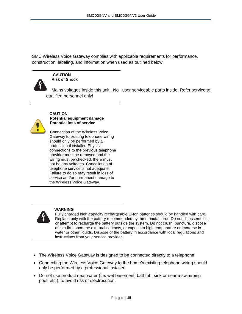
SMC Wireless Voice Gateway complies with applicable requirements for performance,
construction, labeling, and information when used as outlined below:
CAUTION
Risk of Shock
Mains voltages inside this unit. No user serviceable parts inside. Refer service to
qualified personnel only!
CAUTION Potential equipment damage Potential loss of service Connection of the Wireless Voice
Gateway to existing telephone wiring should only be performed by a professional installer. Physical connections to the previous telephone provider must be removed and the wiring must be checked; there must not be any voltages. Cancellation of telephone service is not adequate. Failure to do so may result in loss of service and/or permanent damage to the Wireless Voice Gateway.
WARNING Fully charged high-capacity rechargeable Li-Ion batteries should be handled with care. Replace only with the battery recommended by the manufacturer. Do not disassemble it or attempt to recharge the battery outside the system. Do not crush, puncture, dispose of in a fire, short the external contacts, or expose to high temperature or immerse in water or other liquids. Dispose of the battery in accordance with local regulations and instructions from your service provider.
The Wireless Voice Gateway is designed to be connected directly to a telephone.
Connecting the Wireless Voice Gateway to the home’s existing telephone wiring should only be performed by a professional installer.
Do not use product near water (i.e. wet basement, bathtub, sink or near a swimming pool, etc.), to avoid risk of electrocution.
SMCD3GNV and SMCD3GNV3 User Guide
P a g e | 16
Avoid using and/or connecting the equipment during an electrical storm, to avoid risk of electrocution.
Do not use the telephone to report a gas leak in the vicinity of the leak.
Do not locate the equipment within 6 feet (1.9m) of a flame of ignition source (i.e. heat registers, space heaters, fireplaces, etc.).
Only use power supply and power cord included with the equipment.
Equipment should be installed near the power outlet and should be easily accessible.
The shield of the coaxial cable must be connected to earth (Grounded) at the entrance to the building in accordance with applicable a national electrical installation codes. In the U.S., this is required by NFPA 70 (National Electrical Code) Article 820. In the European Union and in certain other countries, CATV installation equipment bonding requirements are specified in IEC 60728-11, Cable networks for television signals, sound signals and interactive service, Part 11: Safety. This equipment is intended to be installed in accordance with the requirements of IEC 60728-11 for safe operation.
In areas of high surge events or poor grounding situation and areas prone to lightning strikes, additional surge protection may be required (i.e. PF11VNT3 from American Power Conversion) on the AC, RFM Ethernet and Phones lines.
SMCD3GNV and SMCD3GNV3 User Guide
P a g e | 17
Compliance Statements
Federal Communication Commission Interference Statement
This equipment has been tested and found to comply with the limits for a Class B digital device,
pursuant to Part 15 of the FCC Rules. These limits are designed to provide reasonable protection
against harmful interference in a residential installation. This equipment generates, uses and can
radiate radio frequency energy and, if not installed and used in accordance with the instructions, may
cause harmful interference to radio communications. However, there is no guarantee that interference
will not occur in a particular installation.
If this equipment does cause harmful interference to radio or television reception, which can be
determined by turning the equipment off and on, the user is encouraged to try to correct the
interference by one of the following measures:
Reorient or relocate the receiving antenna.
Increase the separation between the equipment and receiver.
Connect the equipment into an outlet on a different circuit from the receiver
Consult the dealer or an experienced radio/TV technician for help.
FCC Caution: Any changes or modifications not expressly approved by the party responsible for
compliance could void the user's authority to operate this equipment.
This device complies with Part 15 of the FCC Rules. Operation is subject to the following two
conditions:
(1) this device may not cause harmful interference and
(2) this device must accept any interference received including interference that may cause undesired operation.
FCC test report reference #: T 100422301-D dated 4/27/2010
UL Certification
This product was tested and found compliant with the following UL standards:
UL 60950-1, 2nd Edition, 2007-03-27 (Information Technology Equipment -
Safety - Part 1: General Requirements)
CSA C22.2 No. 60950-1-07, 2nd Edition, 2007-03 (Information Technology
Equipment - Safety - Part 1: General Requirements)
SMCD3GNV and SMCD3GNV3 User Guide
P a g e | 18
UL test report reference#: E219020-A20-UL-1
IMPORTANT NOTE: FCC Radiation Exposure Statement: This equipment complies with FCC radiation exposure limits set forth for an uncontrolled environment. This equipment should be installed and operated with minimum distance 20cm between the radiator & your body.
This transmitter must not be co-located or operating in conjunction with any other antenna or transmitter.
The availability of some specific channels and/or operational frequency bands are country dependent and are firmware programmed at the factory to match the intended destination. The firmware setting is not accessible by the end user.
Note to CATV System Installer - This reminder is provided to call the CATV systems installer's attention to Section 820-93 of the National Electric Code which provide guideline for proper grounding and, in particular, specify that the Coaxial cable shield shall be connected to the grounding system of the building, as close to the point of cable entry as practical.
FCC Part 68 Statement:
This equipment complies with Part 68 of the FCC Rules. A label is attached to the equipment that contains, among other information, its FCC registration number and ringer equivalence number. If requested, this information must be provided to the telephone company.
This equipment uses the following USOC Jack: RJ-11.
An FCC-compliant telephone cord and modular plug is provided with this equipment. This equipment is designed to be connected to the telephone network or premises wiring using a compatible modular jack, which is FCC Part 68 compliant. Connection to the telephone network should be made by using the standard modular telephone jack.
The REN is useful to determine the quantity of devices that may be connected to the telephone line and still have all of those devices ring when your telephone number is called. In most, but not all areas, the sum of RENs should not exceed 5. To be certain of the number of devices that may be connected to the line, as determined by the total RENs, contact the telephone company to determine the maximum REN for the calling area.
If this equipment causes harm to the telephone network, the telephone company may discontinue your service temporarily. If advance notice is not practical, the telephone company will notify the customer as soon as possible. Also, you will be advised of your right to file a complaint with the FCC if you believe it is necessary.
The telephone company may make changes in its facilities, equipment, operations, or procedures that could affect the operation of the equipment. If this happens, the telephone company will provide advance notice in order for you to make the necessary modifications in order to maintain uninterrupted service.
SMCD3GNV and SMCD3GNV3 User Guide
P a g e | 19
In the event this equipment should fail to operate properly, disconnect the unit from the telephone line. Try using another FCC approved device in the same telephone jack. If the trouble persists, call the telephone company repair service bureau. If the trouble does not persist and appears to be with this unit, disconnect the unit from the telephone line and discontinue use of the unit until it is repaired. Please note that the telephone company may ask that you disconnect the equipment from the telephone network until the problem has been corrected or until you are sure that the equipment is not malfunctioning.
The user must use the accessories and cables supplied by the manufacturer to get optimum performance from the product.
No repairs may be done by the customer. If trouble is experienced with this equipment, please contact your authorized support provider for repair and warranty information. If the trouble is causing harm to the telephone network, the telephone company may request you remove the equipment from the network until the problem is resolved. This equipment cannot be used on telephone company provided coin service. Connection to Party Line Service is subject to state tariffs
GPL / GNU License
This product includes software code developed by third parties, including software code subject to the
GNU General Public License (“GPL”) or GNU Lesser General Public License (LGPL”). As applicable,
the terms of the GPL and LGPL, and information on obtaining access to the GPL code and LGPL
used in this product, are available to you at http://gpl.smc.com/. The GPL code and LGPL code used
in this product is distributed WITHOUT ANY WARRANTY and is subject to the copyrights of one or
more authors. For details, see the GPL Code and LGPL Code for this product and the terms of the
GPL and LGPL.