Embed Size (px)
Citation preview
User ManualF1DP108GF1DP116G
OmniView® SMB KVM-over-IP Switch
OmniView® SMB KVM-over-IP Switch
Table of Contents
1. Introduction ...................................................................................... 1
Package Contents ......................................................................... 1
2. Overview .......................................................................................... 2
Remote-Management Features ..................................................... 2
Other Features ............................................................................... 3
Equipment Requirements .............................................................. 4
System Requirements .................................................................... 6
Unit Display Diagrams ................................................................... 7
Specifications ................................................................................ 8
3. Local Installation ............................................................................11
Pre-Configuration .........................................................................11
Mounting the Switch .....................................................................13
Connecting the Console to the Switch .........................................14
Connecting Servers to the Switch ....................................................... 16
Powering Up the Systems ........................................................... 22
Daisy-Chaining Multiple KVM Switches (Optional) ..................... 23
4. Remote Installation .........................................................................28
Identifying the IP Address.............................................................28
Logging into the Web Interface ................................................... 29
Network Configuration ..................................................................31
User Settings ............................................................................... 33
Switch Configuration ................................................................... 36
Serial Settings .............................................................................. 38
Security Settings ......................................................................... 39
Maintenance .................................................................................41
Table of Contents
5. Using the Switch from a Remote Console ...................................... 43
Starting a Remote Session .................................................................... 43
Using the Drop-Down Bar ..................................................................... 45
Mouse Configuration and Settings ...................................................... 46
Keyboard Configuration and Settings ................................................. 50
Video Configuration and Settings ........................................................ 52
Performance Settings ............................................................................. 54
Selecting a Server.................................................................................... 55
Additional Features .................................................................................. 56
Restoring Factory Defaults .................................................................... 57
6. Using the Switch from a Local Console .......................................... 58
Selecting a Server or BANK .................................................................. 58
AutoScan Mode ........................................................................................ 61
On-Screen Display................................................................................... 62
Hot-Key-Command Shortcuts .............................................................. 66
Sun Combo Keys ..................................................................................... 67
Updating Firmware .................................................................................. 68
7. Frequently Asked Questions .......................................................... 69
8. Troubleshooting ..............................................................................71
9. Glossary ..........................................................................................76
10. Information .....................................................................................78
1
1
2
3
4
5
6
7
8
9
10
section Introduction
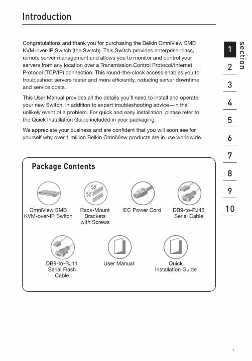
Congratulations and thank you for purchasing the Belkin OmniView SMB KVM-over-IP Switch (the Switch). This Switch provides enterprise-class, remote server management and allows you to monitor and control your servers from any location over a Transmission Control Protocol/Internet Protocol (TCP/IP) connection. This round-the-clock access enables you to troubleshoot servers faster and more efficiently, reducing server downtime and service costs.
This User Manual provides all the details you’ll need to install and operate your new Switch, in addition to expert troubleshooting advice—in the unlikely event of a problem. For quick and easy installation, please refer to the Quick Installation Guide included in your packaging.
We appreciate your business and are confident that you will soon see for yourself why over 1 million Belkin OmniView products are in use worldwide.
Rack-Mount Brackets
with Screws
IEC Power CordOmniView SMB KVM-over-IP Switch
User Manual Quick Installation Guide
Package Contents
DB9-to-RJ11 Serial Flash
Cable
DB9-to-RJ45 Serial Cable
2
Overview
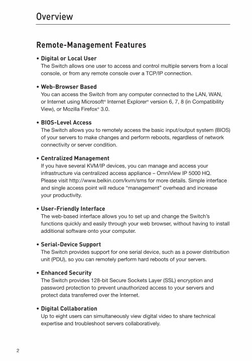
Remote-Management Features•DigitalorLocalUser
The Switch allows one user to access and control multiple servers from a local console, or from any remote console over a TCP/IP connection.
•Web-BrowserBased You can access the Switch from any computer connected to the LAN, WAN, or Internet using Microsoft® Internet Explorer® version 6, 7, 8 (in Compatibility View), or Mozilla Firefox® 3.0.
•BIOS-LevelAccess The Switch allows you to remotely access the basic input/output system (BIOS) of your servers to make changes and perform reboots, regardless of network connectivity or server condition.
•CentralizedManagement If you have several KVM/IP devices, you can manage and access your infrastructure via centralized access appliance – OmniView IP 5000 HQ. Please visit http://www.belkin.com/kvm/sms for more details. Simple interface and single access point will reduce “management” overhead and increase your productivity.
•User-FriendlyInterface The web-based interface allows you to set up and change the Switch’s functions quickly and easily through your web browser, without having to install additional software onto your computer.
•Serial-DeviceSupport The Switch provides support for one serial device, such as a power distribution unit (PDU), so you can remotely perform hard reboots of your servers.
•EnhancedSecurity The Switch provides 128-bit Secure Sockets Layer (SSL) encryption and password protection to prevent unauthorized access to your servers and protect data transferred over the Internet.
•DigitalCollaboration Up to eight users can simultaneously view digital video to share technical expertise and troubleshoot servers collaboratively.
3
1
2
3
4
5
6
7
8
9
10
section Overview
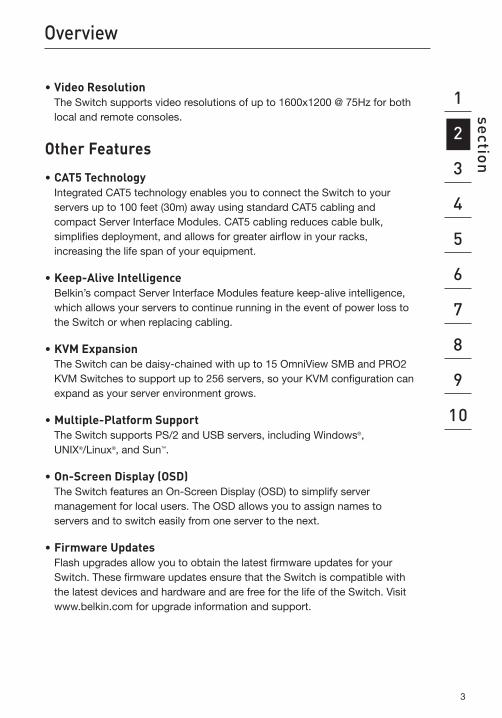
•VideoResolution The Switch supports video resolutions of up to 1600x1200 @ 75Hz for both local and remote consoles.
Other Features
•CAT5Technology Integrated CAT5 technology enables you to connect the Switch to your servers up to 100 feet (30m) away using standard CAT5 cabling and compact Server Interface Modules. CAT5 cabling reduces cable bulk, simplifies deployment, and allows for greater airflow in your racks, increasing the life span of your equipment.
•Keep-AliveIntelligence Belkin’s compact Server Interface Modules feature keep-alive intelligence, which allows your servers to continue running in the event of power loss to the Switch or when replacing cabling.
•KVMExpansion The Switch can be daisy-chained with up to 15 OmniView SMB and PRO2 KVM Switches to support up to 256 servers, so your KVM configuration can expand as your server environment grows.
•Multiple-PlatformSupport The Switch supports PS/2 and USB servers, including Windows®, UNIX®/Linux®, and Sun™.
•On-ScreenDisplay(OSD) The Switch features an On-Screen Display (OSD) to simplify server management for local users. The OSD allows you to assign names to servers and to switch easily from one server to the next.
•FirmwareUpdates Flash upgrades allow you to obtain the latest firmware updates for your Switch. These firmware updates ensure that the Switch is compatible with the latest devices and hardware and are free for the life of the Switch. Visit www.belkin.com for upgrade information and support.
44
Overview
EquipmentRequirements
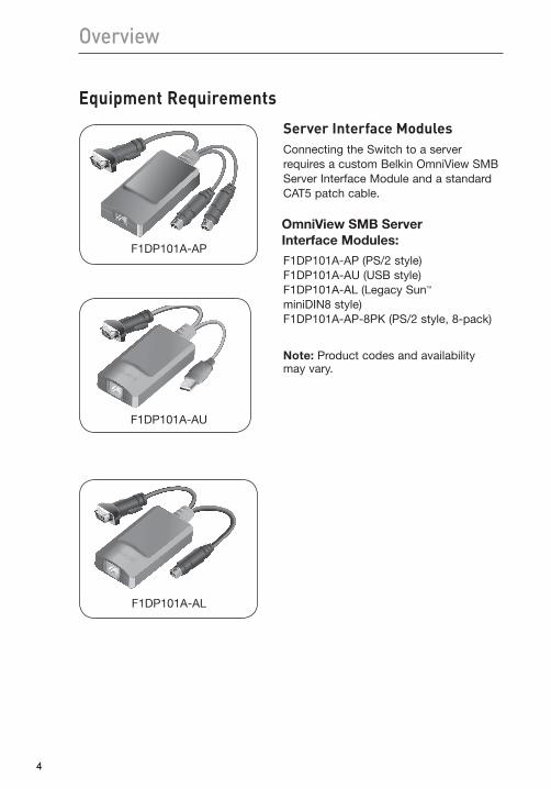
Server Interface ModulesConnecting the Switch to a server requires a custom Belkin OmniView SMB Server Interface Module and a standard CAT5 patch cable.
OmniView SMB Server Interface Modules:
F1DP101A-AP (PS/2 style) F1DP101A-AU (USB style) F1DP101A-AL (Legacy Sun™ miniDIN8 style) F1DP101A-AP-8PK (PS/2 style, 8-pack)
Note: Product codes and availability may vary.
F1DP101A-AP
F1DP101A-AU
F1DP101A-AL
5
1
2
3
4
5
6
7
8
9
10
section Overview
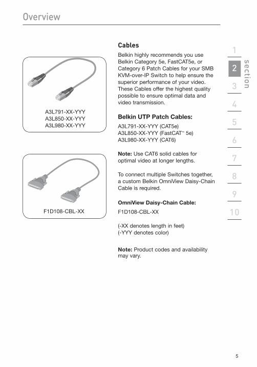
CablesBelkin highly recommends you use Belkin Category 5e, FastCAT5e, or Category 6 Patch Cables for your SMB KVM-over-IP Switch to help ensure the superior performance of your video. These Cables offer the highest quality possible to ensure optimal data and video transmission.
Belkin UTP Patch Cables:
A3L791-XX-YYY (CAT5e) A3L850-XX-YYY (FastCAT™ 5e) A3L980-XX-YYY (CAT6)
Note: Use CAT6 solid cables for optimal video at longer lengths.
To connect multiple Switches together, a custom Belkin OmniView Daisy-Chain Cable is required.
OmniView Daisy-Chain Cable:
F1D108-CBL-XX
(-XX denotes length in feet) (-YYY denotes color)
Note: Product codes and availability may vary.
F1D108-CBL-XX
A3L791-XX-YYY A3L850-XX-YYY A3L980-XX-YYY
6
Overview
System Requirements
Operating-System(OS)PlatformsThe SMB KVM-over-IP Switch is compatible with CPUs running on, but not limited to, the following OS platforms:
•Windows® NT®, 2000, Server 2003, Server 2008, XP, Vista®, or Windows 7
•Microsoft® DOS 5.x and above
•RedHat® Linux® 8.x and above
•Sun™
•Novell™ 5.x
•Solaris™ 8.x and above
Keyboards•PS/2-compatible
Mice•PS/2-compatiblewith2,3,4,or5buttons
•PS/2-compatiblewirelessandopticalmice
Monitors•CRTandLCD(withVGAsupport)
Remote-Console SoftwareThe SMB Remote IP Device may be accessed remotely over a TCP/IP connection from computers using the following web browsers and OS platforms:
•MicrosoftInternetExplorer6.0,7.0,andabovewithActiveX® support
•MicrosoftInternetExplorer8.0inCompatibilityView
•MozillaFirefox3.0andlater
•Windows2000,XP,Server2003,orServer2008
•WindowsVista®**, Windows 7**
•RedHat,SUSE,andFedoraDesktopLinuxdistributions
Note: Belkin Remote Console doesn’t support 64-bit browsers.
7
1
2
3
4
5
6
7
8
9
10
section Overview
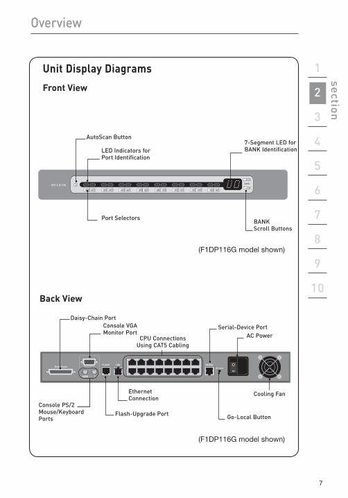
(F1DP116G model shown)
AutoScan Button7-Segment LED for BANK Identification
Port Selectors BANK Scroll Buttons
LED Indicators for Port Identification
Daisy-Chain PortConsole VgA Monitor Port
Flash-Upgrade PortConsole PS/2 Mouse/Keyboard Ports
CPU Connections Using CAT5 Cabling
Serial-Device Port
Ethernet Connection
go-Local Button
AC Power
Cooling Fan
Back View
UnitDisplayDiagrams
Front View
(F1DP116G model shown)
8
Overview
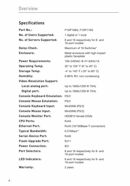
SpecificationsPart No.: F1DP108G, F1DP116G
No.ofUsersSupported: 1 digital or 1 local
No.ofServersSupported: 8 and 16 respectively for 8- and 16-port models
Daisy-Chain: Maximum of 16 Switches*
Enclosure: Metal enclosure with high-impact plastic faceplate
Power Requirements: 100–240VAC @ 47–63Hz/1A
OperatingTemp: 32° to 104° F (0° to 40° C)
StorageTemp: -4° to 140° F (-20° to 60° C)
Humidity: 0-80% RH, non-condensing
Video-ResolutionSupport:
Localanalogport: Up to 1600x1200 @ 75Hz
Digitalport: Up to 1600x1200 @ 75Hz
ConsoleKeyboardEmulation: PS/2
ConsoleMouseEmulation: PS/2
ConsoleKeyboardInput: MiniDIN6 (PS/2)
ConsoleMouseInput: MiniDIN6 (PS/2)
Console Monitor Port: HDDB15 female (VGA)
CPU Ports: RJ45
EthernetPort: RJ45 (10/100Base-T connection)
TypicalBandwidth: 0.31Mbps**
Serial-DevicePort: RJ45
Flash-UpgradePort: RJ11
Power Connection: IEC
Port Selectors: 8 and 16 respectively for 8- and 16-port models
LEDIndicators: 8 and 16 respectively for 8- and 16-port models
Warranty: 2 years
9
1
2
3
4
5
6
7
8
9
10
section Overview
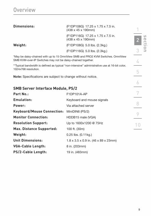
Dimensions: (F1DP108G) 17.25 x 1.75 x 7.5 in. (438 x 45 x 190mm)
(F1DP116G) 17.25 x 1.75 x 7.5 in. (438 x 45 x 190mm)
Weight: (F1DP108G) 5.0 lbs. (2.3kg.)
(F1DP116G) 5.0 lbs. (2.3kg.)
*May be daisy-chained with up to 15 OmniView SMB and PRO2 KVM Switches. OmniView SMB KVM-over-IP Switches may not be daisy-chained together.
**Typical bandwidth is defined as typical “non-intensive” administrative use at 16-bit color, 1024x768 resolution.
Note: Specifications are subject to change without notice.
SMB Server Interface Module, PS/2Part No.: F1DP101A-AP
Emulation: Keyboard and mouse signals
Power: Via attached server
Keyboard/Mouse Connection: MiniDIN6 (PS/2)
Monitor Connection: HDDB15 male (VGA)
ResolutionSupport: Up to 1600x1200 @ 75Hz
Max.DistanceSupported: 100 ft. (30m)
Weight: 0.25 lbs. (0.11kg.)
UnitDimensions: 1.8 x 3.5 x 0.9 in. (46 x 89 x 23mm)
VGA-Cable Length: 8 in. (203mm)
PS/2-Cable Length: 19 in. (483mm)
10
Overview
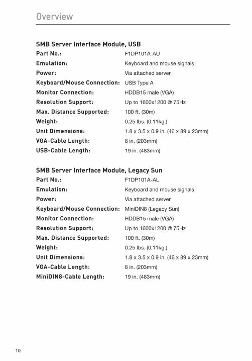
SMB Server Interface Module, USBPart No.: F1DP101A-AU
Emulation: Keyboard and mouse signals
Power: Via attached server
Keyboard/Mouse Connection: USB Type A
Monitor Connection: HDDB15 male (VGA)
ResolutionSupport: Up to 1600x1200 @ 75Hz
Max.DistanceSupported: 100 ft. (30m)
Weight: 0.25 lbs. (0.11kg.)
UnitDimensions: 1.8 x 3.5 x 0.9 in. (46 x 89 x 23mm)
VGA-Cable Length: 8 in. (203mm)
USB-Cable Length: 19 in. (483mm)
SMB Server Interface Module, Legacy SunPart No.: F1DP101A-AL
Emulation: Keyboard and mouse signals
Power: Via attached server
Keyboard/Mouse Connection: MiniDIN8 (Legacy Sun)
Monitor Connection: HDDB15 male (VGA)
ResolutionSupport: Up to 1600x1200 @ 75Hz
Max.DistanceSupported: 100 ft. (30m)
Weight: 0.25 lbs. (0.11kg.)
UnitDimensions: 1.8 x 3.5 x 0.9 in. (46 x 89 x 23mm)
VGA-Cable Length: 8 in. (203mm)
MiniDIN8-CableLength: 19 in. (483mm)
11
1
2
3
4
5
6
7
8
9
10
section Local Installation
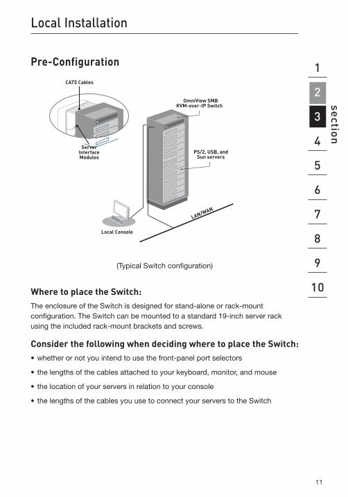
Pre-Configuration
(Typical Switch configuration)
WheretoplacetheSwitch:The enclosure of the Switch is designed for stand-alone or rack-mount configuration. The Switch can be mounted to a standard 19-inch server rack using the included rack-mount brackets and screws.
ConsiderthefollowingwhendecidingwheretoplacetheSwitch:•whetherornotyouintendtousethefront-panelportselectors
•thelengthsofthecablesattachedtoyourkeyboard,monitor,andmouse
•thelocationofyourserversinrelationtoyourconsole
•thelengthsofthecablesyouusetoconnectyourserverstotheSwitch
12
Local Installation
Cable-DistanceRequirements(forPS/2,USB,andSunServers)VGA signals transmit best up to 100 feet (30m). Beyond that length, the probability of video degradation increases. For this reason, Belkin recommends that the length of the CAT5 UTP cable between the Switch and the connected servers does not exceed 100 feet (30m).
Note: The Belkin CAT5 Extender (F1D084) may be used to extend your console (keyboard, mouse, and monitor) by up to 300 feet (91m).
Warning: Avoid placing cables near fluorescent lights, air-conditioning equipment, or machines that create electrical noise (e.g., vacuum cleaners).
You are now ready to begin installation of your Switch. The following sections (pages 13–22) provide complete instructions for the hardware setup of a single Switch (F1DP108G, F1DP116G).
13
1
2
3
4
5
6
7
8
9
10
section Local Installation
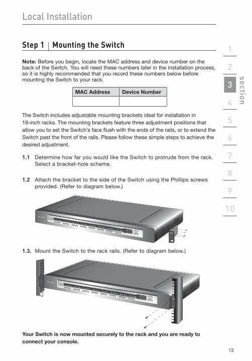
Step1 MountingtheSwitch
Note: Before you begin, locate the MAC address and device number on the back of the Switch. You will need these numbers later in the installation process, so it is highly recommended that you record these numbers below before mounting the Switch to your rack.
MAC Address Device Number
The Switch includes adjustable mounting brackets ideal for installation in 19-inch racks. The mounting brackets feature three adjustment positions that allow you to set the Switch’s face flush with the ends of the rails, or to extend the Switch past the front of the rails. Please follow these simple steps to achieve the desired adjustment.
1.1 Determine how far you would like the Switch to protrude from the rack. Select a bracket-hole scheme.
1.2 Attach the bracket to the side of the Switch using the Phillips screws provided. (Refer to diagram below.)
1.3. Mount the Switch to the rack rails. (Refer to diagram below.)
Your Switch is now mounted securely to the rack and you are ready to connect your console.
14
Local Installation
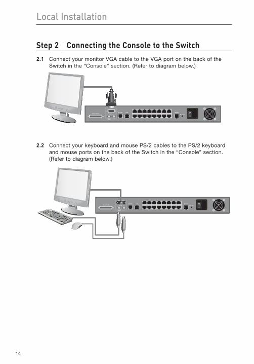
Step2 ConnectingtheConsoletotheSwitch2.1 Connect your monitor VGA cable to the VGA port on the back of the
Switch in the “Console” section. (Refer to diagram below.)
2.2 Connect your keyboard and mouse PS/2 cables to the PS/2 keyboard and mouse ports on the back of the Switch in the “Console” section. (Refer to diagram below.)
15
1
2
3
4
5
6
7
8
9
10
section Local Installation
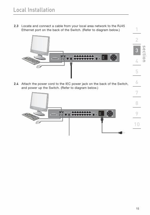
2.3 Locate and connect a cable from your local area network to the RJ45 Ethernet port on the back of the Switch. (Refer to diagram below.)
2.4 Attach the power cord to the IEC power jack on the back of the Switch, and power up the Switch. (Refer to diagram below.)
16
Local Installation
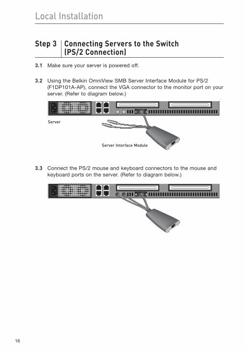
Step3 ConnectingServerstotheSwitch (PS/2Connection)
3.1 Make sure your server is powered off.
3.2 Using the Belkin OmniView SMB Server Interface Module for PS/2 (F1DP101A-AP), connect the VGA connector to the monitor port on your server. (Refer to diagram below.)
3.3 Connect the PS/2 mouse and keyboard connectors to the mouse and keyboard ports on the server. (Refer to diagram below.)
Server
Server Interface Module
17
1
2
3
4
5
6
7
8
9
10
section Local Installation
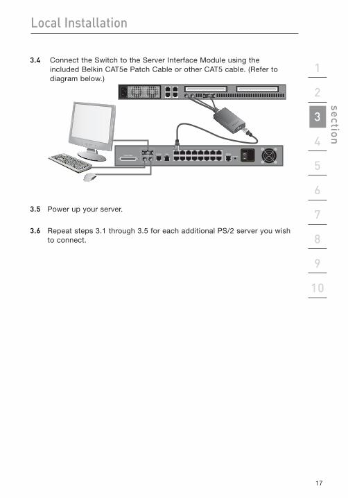
3.4 Connect the Switch to the Server Interface Module using the included Belkin CAT5e Patch Cable or other CAT5 cable. (Refer to diagram below.)
3.5 Power up your server.
3.6 Repeat steps 3.1 through 3.5 for each additional PS/2 server you wish to connect.
18
Local Installation
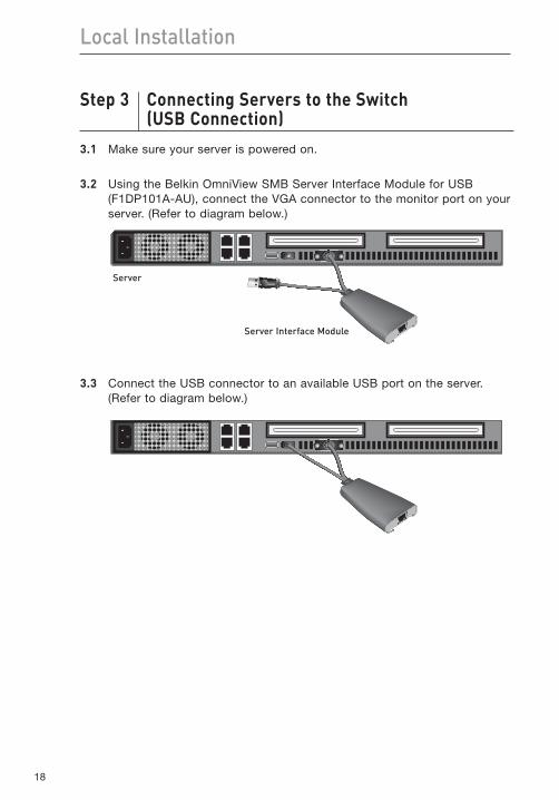
Step3 ConnectingServerstotheSwitch (USBConnection)
3.1 Make sure your server is powered on.
3.2 Using the Belkin OmniView SMB Server Interface Module for USB (F1DP101A-AU), connect the VGA connector to the monitor port on your server. (Refer to diagram below.)
3.3 Connect the USB connector to an available USB port on the server. (Refer to diagram below.)
Server
Server Interface Module
19
1
2
3
4
5
6
7
8
9
10
section Local Installation
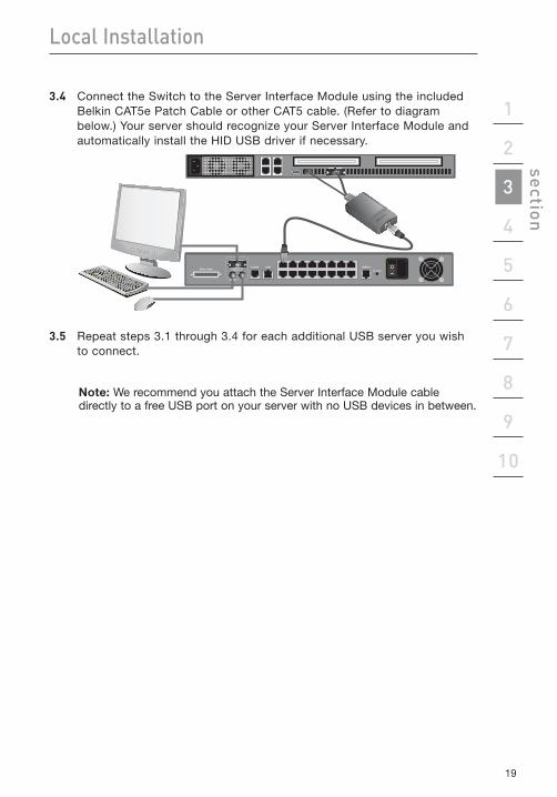
3.4 Connect the Switch to the Server Interface Module using the included Belkin CAT5e Patch Cable or other CAT5 cable. (Refer to diagram below.) Your server should recognize your Server Interface Module and automatically install the HID USB driver if necessary.
3.5 Repeat steps 3.1 through 3.4 for each additional USB server you wish to connect.
Note: We recommend you attach the Server Interface Module cable directly to a free USB port on your server with no USB devices in between.
2020
Local Installation
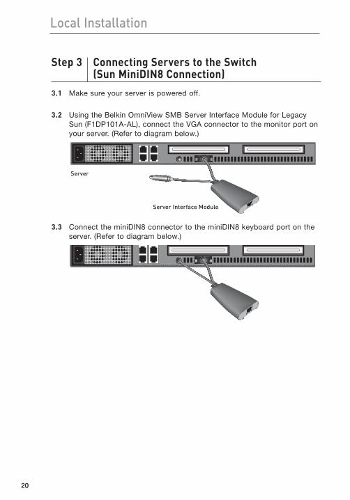
Step3 ConnectingServerstotheSwitch (SunMiniDIN8Connection)
3.1 Make sure your server is powered off.
3.2 Using the Belkin OmniView SMB Server Interface Module for Legacy Sun (F1DP101A-AL), connect the VGA connector to the monitor port on your server. (Refer to diagram below.)
3.3 Connect the miniDIN8 connector to the miniDIN8 keyboard port on the server. (Refer to diagram below.)
Server
Server Interface Module
21
1
2
3
4
5
6
7
8
9
10
section Local Installation
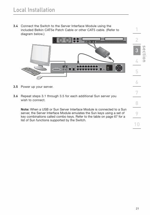
3.4 Connect the Switch to the Server Interface Module using the included Belkin CAT5e Patch Cable or other CAT5 cable. (Refer to diagram below.)
3.5 Power up your server.
3.6 Repeat steps 3.1 through 3.5 for each additional Sun server you wish to connect.
Note: When a USB or Sun Server Interface Module is connected to a Sun server, the Server Interface Module emulates the Sun keys using a set of key combinations called combo keys. Refer to the table on page 67 for a list of Sun functions supported by the Switch.
22
Local Installation
Step4 PoweringUptheSystems4.1 If you have not already done so, power on all servers connected to
the Switch (servers can be powered on simultaneously). The Switch emulates both a mouse and keyboard on each port and allows your server to boot normally. The server connected to port 1 will be displayed on the monitor.
4.2 Check that the keyboard, monitor, and mouse are working normally.
4.3 Using the port selectors, check all occupied ports to verify that all servers are connected and responding correctly. If you encounter an error, check your cable connections for that server and reboot. If the problem persists, please refer to the “Troubleshooting” section in this User Manual.
23
1
2
3
4
5
6
7
8
9
10
section Local Installation
Daisy-ChainingMultipleKVMSwitches(Optional)
Note: If you are only installing a single SMB KVM-over-IP Switch, skip to the “Remote Installation” section on page 28.
You can daisy-chain up to 15 additional OmniView SMB and PRO2 KVM Switches to your OmniView SMB KVM-over-IP Switch, allowing a server administrator to manage up to a maximum of 256 servers from one local or remote console. Each daisy-chained KVM Switch is referred to as a “BANK” and is assigned an address. The SMB KVM-over-IP Switch connected to the console keyboard, mouse, and monitor can only function as the “primary” KVM switch. BANKs 01 through 15 are referred to as “secondary” KVM switches.
Note: The SMB KVM-over-IP Switch can only function as the primary KVM switch. You cannot daisy-chain two SMB KVM-over-IP Switches together.
Note: A Daisy-Chain Cable (F1D108-CBL-XX) is required to daisy-chain each KVM Switch and is available through your Belkin reseller, or online at www.belkin.com (U.S. only).
How to Assign a BANK AddressAll SMB CAT5 and PRO2 KVM Switches feature a “BANK DIP” switch. The “BANK DIP” switch is used to assign the proper BANK address to each KVM Switch.
•Foramultiunitconfiguration,the“BANKDIP”switchforeachsecondaryunitmust be set to a unique BANK address (from 01 through 15). For SMB CAT5 KVM Switches, refer to the chart on page 24 for “BANK DIP” switch settings. For PRO2 KVM Switches, refer to the PRO2 User Manual for “BANK DIP” switch settings.
24
Local Installation
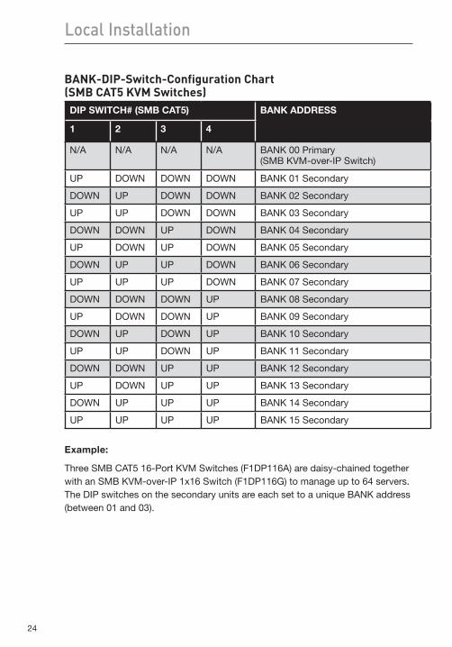
BANK-DIP-Switch-ConfigurationChart (SMBCAT5KVMSwitches)
DIP SWITCH# (SMB CAT5) BANK ADDRESS
1 2 3 4
N/A N/A N/A N/A BANK 00 Primary (SMB KVM-over-IP Switch)
UP DOWN DOWN DOWN BANK 01 Secondary
DOWN UP DOWN DOWN BANK 02 Secondary
UP UP DOWN DOWN BANK 03 Secondary
DOWN DOWN UP DOWN BANK 04 Secondary
UP DOWN UP DOWN BANK 05 Secondary
DOWN UP UP DOWN BANK 06 Secondary
UP UP UP DOWN BANK 07 Secondary
DOWN DOWN DOWN UP BANK 08 Secondary
UP DOWN DOWN UP BANK 09 Secondary
DOWN UP DOWN UP BANK 10 Secondary
UP UP DOWN UP BANK 11 Secondary
DOWN DOWN UP UP BANK 12 Secondary
UP DOWN UP UP BANK 13 Secondary
DOWN UP UP UP BANK 14 Secondary
UP UP UP UP BANK 15 Secondary
Example:
Three SMB CAT5 16-Port KVM Switches (F1DP116A) are daisy-chained together with an SMB KVM-over-IP 1x16 Switch (F1DP116G) to manage up to 64 servers. The DIP switches on the secondary units are each set to a unique BANK address (between 01 and 03).
25
1
2
3
4
5
6
7
8
9
10
section Local Installation
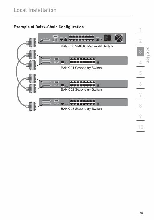
ExampleofDaisy-ChainConfiguration
BANK 00 SMB KVM-over-IP Switch
BANK 01 Secondary Switch
BANK 02 Secondary Switch
BANK 03 Secondary Switch
2626
Local Installation
Getting Started:1. Make sure that all servers and Switches are powered off and that each
KVM Switch has been assigned a unique BANK address.
2. Place the SMB KVM-over-IP Switch and all secondary KVM Switches in the desired location.
3. Connect the console monitor, keyboard, and mouse to the console ports of the SMB KVM-over-IP Switch. Refer to “Connecting the Console to the Switch” on page 14.
Connecting the Primary and Secondary KVM Switches:1. Using the Daisy-Chain Cable (F1D108-CBL-XX), connect one end to the
“Daisy-Chain” port on the SMB KVM-over-IP Switch.
2. Connect the other end of the Daisy-Chain Cable to the “Primary Input/Secondary Output” port of the first secondary KVM Switch (BANK 01).
3. To add secondary units, connect one end of the Daisy-Chain Cable to the “Secondary Input” on the first secondary KVM Switch and the other end to the “Primary Input/Secondary Output” port of the next secondary KVM Switch (for example, BANK 01).
4. Repeat step 3 for additional KVM Switches you wish to add to your daisy-chain configuration.
27
1
2
3
4
5
6
7
8
9
10
section
2727
Local Installation
Connecting the servers:1. Connect all servers to the SMB KVM-over-IP Switch and secondary KVM
Switches. Refer to the “Connecting Servers to the Switch” section on page 16 for instructions.
2. Make sure that the power adapter is connected to the SMB KVM-over-IP Switch and that the Switch is powered on. You should see the Switch light up and display the digits “00”, indicating its BANK address.
3. Power up the secondary KVM Switches sequentially, beginning with BANK 01, by connecting each unit’s power supply. Each KVM Switch should display its corresponding BANK address number as it is powered up.
Note: If the secondary KVM Switches do not enumerate correctly, reset the SMB KVM-over-IP Switch (BANK 00) by simultaneously pressing the “BANK +” and “BANK –” buttons. You can also reset the primary switch to detect newly added secondary KVM Switches. If the KVM Switches still do not enumerate correctly, check that all KVM Switches have the correct BANK address assigned to them and that all daisy-chain cables are connected properly.
4. Verify that the SMB KVM-over-IP Switch has detected all secondary KVM Switches by scrolling through the BANKs using the “BANK +” and “BANK –” buttons. If all secondary KVM Switches are detected properly, the LED display on the primary KVM Switch will register and display the BANK address of the attached secondary KVM Switch.
28
Remote Installation
Step1 IdentifyingtheIPAddress
Once your Switch has been connected to your network and is powered up, a Dynamic Host Configuration Protocol (DHCP) server on your network will automatically assign the Switch an IP address, gateway address, and subnet mask.
To identify the IP address on your network, use the MAC address or unique device number located on the back of the Switch. If no DHCP server is found on your network, the Switch will boot with the following static IP address: 192.168.2.155.
If you want to connect more than one Switch to the same network and there is no DHCP server available, connect each Switch to your network one at a time and change the static IP address of each unit before connecting the next unit.
Note: If a DHCP server later becomes available on your network, the Switch will take a new IP address from the DHCP server. To keep the original static IP address, you will need to disable DHCP (see page 32).
29
1
2
3
4
5
6
7
8
9
10
section Remote Installation
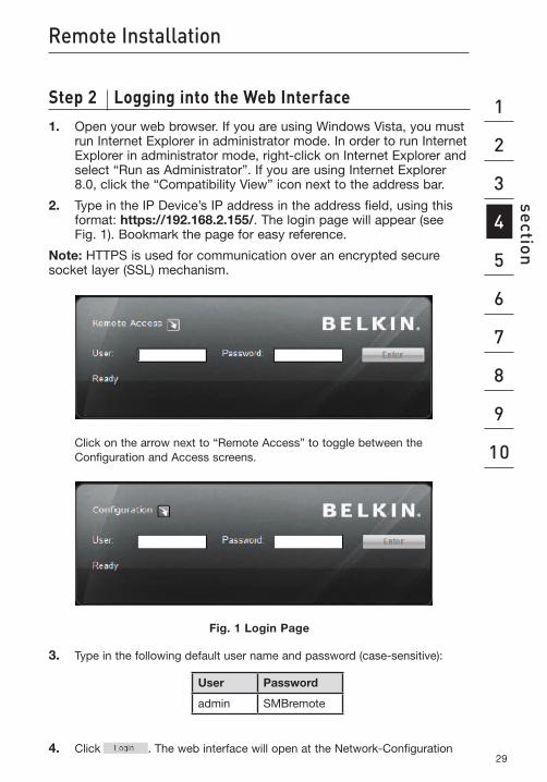
Step2 LoggingintotheWebInterface1. Open your web browser. If you are using Windows Vista, you must
run Internet Explorer in administrator mode. In order to run Internet Explorer in administrator mode, right-click on Internet Explorer and select “Run as Administrator”. If you are using Internet Explorer 8.0, click the “Compatibility View” icon next to the address bar.
2. Type in the IP Device’s IP address in the address field, using this format: https://192.168.2.155/. The login page will appear (see Fig. 1). Bookmark the page for easy reference.
Note: HTTPS is used for communication over an encrypted secure socket layer (SSL) mechanism.
Click on the arrow next to “Remote Access” to toggle between the Configuration and Access screens.
Fig. 1 Login Page
3. Type in the following default user name and password (case-sensitive):
User Password
admin SMBremote
4. Click . The web interface will open at the Network-Configuration
30
Remote Installation
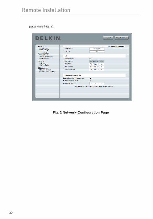
page (see Fig. 2).
Fig. 2 Network-Configuration Page
31
1
2
3
4
5
6
7
8
9
10
section Remote Installation
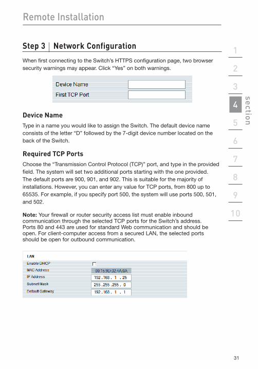
Step3 NetworkConfiguration
When first connecting to the Switch’s HTTPS configuration page, two browser security warnings may appear. Click “Yes” on both warnings.
DeviceNameType in a name you would like to assign the Switch. The default device name consists of the letter “D” followed by the 7-digit device number located on the back of the Switch.
Required TCP PortsChoose the “Transmission Control Protocol (TCP)” port, and type in the provided field. The system will set two additional ports starting with the one provided. The default ports are 900, 901, and 902. This is suitable for the majority of installations. However, you can enter any value for TCP ports, from 800 up to 65535. For example, if you specify port 500, the system will use ports 500, 501, and 502.
Note: Your firewall or router security access list must enable inbound communication through the selected TCP ports for the Switch’s address. Ports 80 and 443 are used for standard Web communication and should be open. For client-computer access from a secured LAN, the selected ports should be open for outbound communication.
32
Remote Installation
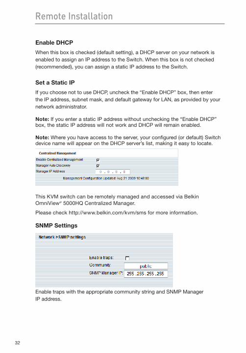
Enable DHCP
When this box is checked (default setting), a DHCP server on your network is enabled to assign an IP address to the Switch. When this box is not checked (recommended), you can assign a static IP address to the Switch.
Set a Static IP
If you choose not to use DHCP, uncheck the “Enable DHCP” box, then enter the IP address, subnet mask, and default gateway for LAN, as provided by your network administrator.
Note: If you enter a static IP address without unchecking the “Enable DHCP” box, the static IP address will not work and DHCP will remain enabled.
Note: Where you have access to the server, your configured (or default) Switch device name will appear on the DHCP server’s list, making it easy to locate.
This KVM switch can be remotely managed and accessed via Belkin OmniViewIP 5000HQ Centralized Manager.
Please check http://www.belkin.com/kvm/sms for more information.
SNMP Settings
Enable traps with the appropriate community string and SNMP Manager IP address.
33
1
2
3
4
5
6
7
8
9
10
section Remote Installation
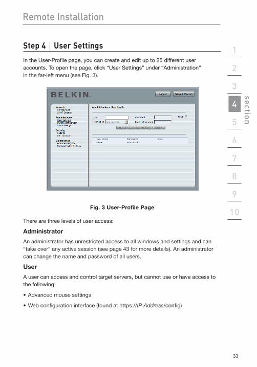
Step4 UserSettings
In the User-Profile page, you can create and edit up to 25 different user accounts. To open the page, click “User Settings” under “Administration” in the far-left menu (see Fig. 3).
Fig. 3 User-Profile Page
There are three levels of user access:
Administrator
An administrator has unrestricted access to all windows and settings and can “take over” any active session (see page 43 for more details). An administrator can change the name and password of all users.
User
A user can access and control target servers, but cannot use or have access to the following:
•Advancedmousesettings
•Webconfigurationinterface(foundathttps://IP Address/config)
34
Remote Installation
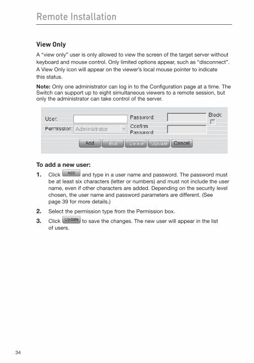
View OnlyA “view only” user is only allowed to view the screen of the target server without keyboard and mouse control. Only limited options appear, such as “disconnect”. A View Only icon will appear on the viewer’s local mouse pointer to indicate this status.
Note: Only one administrator can log in to the Configuration page at a time. The Switch can support up to eight simultaneous viewers to a remote session, but only the administrator can take control of the server.
To add a new user:
1. Click and type in a user name and password. The password must be at least six characters (letter or numbers) and must not include the user name, even if other characters are added. Depending on the security level chosen, the user name and password parameters are different. (See page 39 for more details.)
2. Select the permission type from the Permission box.
3. Click to save the changes. The new user will appear in the list of users.
35
1
2
3
4
5
6
7
8
9
10
section Remote Installation
To edit a user:
1. Select the user from the list.
2. Click . You can now change all the available parameters—user name, permission type, and password.
3. Click to save the changes.
Note: For security, you should change the password for the default “admin” user name.
To delete a user:
1. Select the user from the list.
2. Click .
3. Click to save the changes.
Blocking a standard user and “View Only” user
An alternative to deleting a user is “blocking.” This means that the user’s name and password remained stored, but the user is unable to access the system.
To block a user:
1. Select the user from the list.
2. Check the “Block” box.
3. Click to save the changes.
Note: For security purposes, we recommend that you delete administrator accounts and not use this blocking feature.
36
Remote Installation
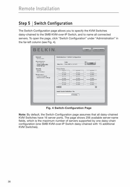
Step5 SwitchConfiguration
The Switch-Configuration page allows you to specify the KVM Switches daisy-chained to the SMB KVM-over-IP Switch, and to name all connected servers. To open the page, click “Switch Configuration” under “Administration” in the far-left column (see Fig. 4).
Fig. 4 Switch-Configuration Page
Note: By default, the Switch-Configuration page assumes that all daisy-chained KVM Switches have 16 server ports. The page shows 256 available server-name fields, which is the maximum number of servers supported by one daisy-chain configuration (one SMB KVM-over-IP Switch daisy-chained with 15 additional KVM Switches).
37
1
2
3
4
5
6
7
8
9
10
section Remote Installation
Tospecifyandnameservers:1. Click next to the Daisy-Chain field and select the KVM-switch
configuration that best suits your configuration.
2. Click . The number of possible connected servers will appear in the Server Name section.
3. Change the name of each connected server by highlighting the server and typing in a new name.
4. Click . to save the changes.
Note: You will need to change the name of every server you want to access. Server names left as “UNUSED” cannot be accessed.
InstallingnewSwitch-DefinitionFiles(SDFs)If your switch-configuration type is not listed in the Daisy-Chain drop-down list, contact Belkin Technical Support at (800) 282-2355 to request an updated SDF with the desired KVM-configuration list.
To install the SDF:
1. Load the file onto the client computer.
2. Click to locate the new SDF.
3. Click “Install” to update the Switch with the new file.
Note: If you change the hot-key sequence in the local OSD to “Print Screen”, “Ctrl”, or “F12”, you must load a new switch-definition file (SDF) for the corresponding hot key. The SDF can be downloaded from www.belkin.com/support.
38
Remote Installation
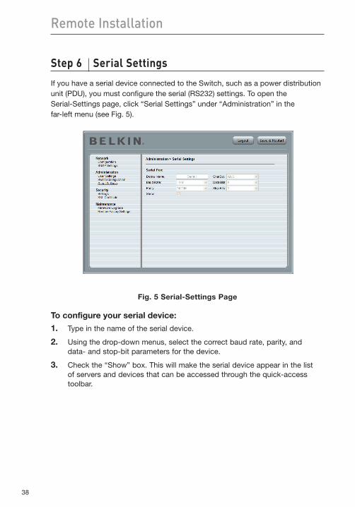
Step6 SerialSettings
If you have a serial device connected to the Switch, such as a power distribution unit (PDU), you must configure the serial (RS232) settings. To open the Serial-Settings page, click “Serial Settings” under “Administration” in the far-left menu (see Fig. 5).
Fig. 5 Serial-Settings Page
To configure your serial device:
1. Type in the name of the serial device.
2. Using the drop-down menus, select the correct baud rate, parity, and data- and stop-bit parameters for the device.
3. Check the “Show” box. This will make the serial device appear in the list of servers and devices that can be accessed through the quick-access toolbar.
39
1
2
3
4
5
6
7
8
9
10
section Remote Installation
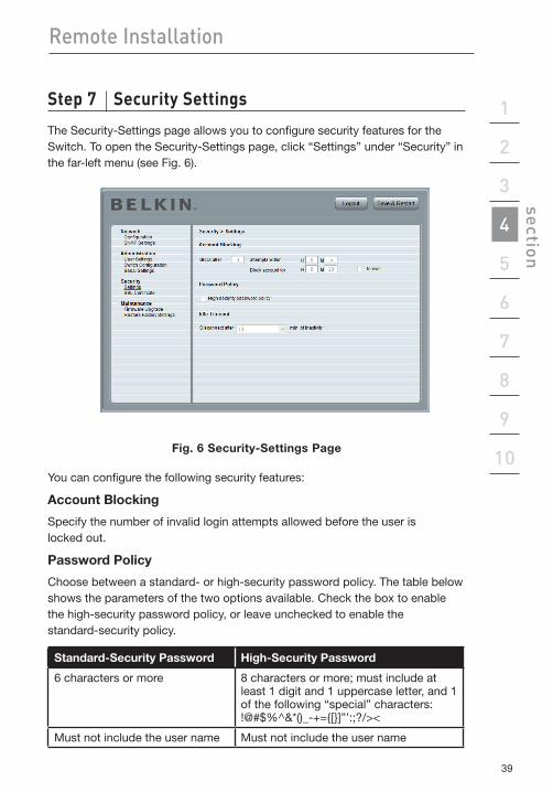
Step7 SecuritySettings
The Security-Settings page allows you to configure security features for the Switch. To open the Security-Settings page, click “Settings” under “Security” in the far-left menu (see Fig. 6).
Fig. 6 Security-Settings Page
You can configure the following security features:
Account Blocking
Specify the number of invalid login attempts allowed before the user is locked out.
Password Policy
Choose between a standard- or high-security password policy. The table below shows the parameters of the two options available. Check the box to enable the high-security password policy, or leave unchecked to enable the standard-security policy.
Standard-Security Password High-Security Password
6 characters or more 8 characters or more; must include at least 1 digit and 1 uppercase letter, and 1 of the following “special” characters: !@#$%^&*()_-+={[}]”’:;?/><
Must not include the user name Must not include the user name
40
Remote Installation
Idle TimeoutSelect the maximum time allowed for inactivity before the user is disconnected from the remote session. Choose “No Timeout” to disable the Idle Timeout feature. By default, the timeout inactivity period is set to 10 minutes.
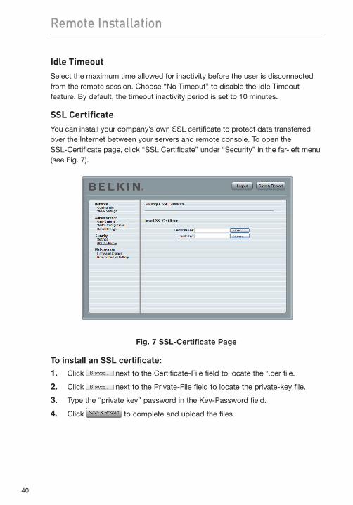
SSL CertificateYou can install your company’s own SSL certificate to protect data transferred over the Internet between your servers and remote console. To open the SSL-Certificate page, click “SSL Certificate” under “Security” in the far-left menu (see Fig. 7).
Fig. 7 SSL-Certificate Page
To install an SSL certificate:
1. Click next to the Certificate-File field to locate the *.cer file.
2. Click next to the Private-File field to locate the private-key file.
3. Type the “private key” password in the Key-Password field.
4. Click to complete and upload the files.
41
1
2
3
4
5
6
7
8
9
10
section Remote Installation
Maintenance
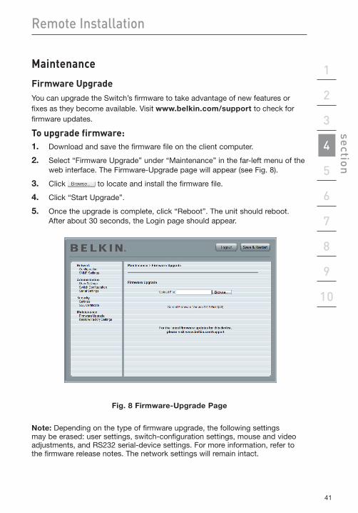
FirmwareUpgradeYou can upgrade the Switch’s firmware to take advantage of new features or fixes as they become available. Visit www.belkin.com/support to check for firmware updates.
Toupgradefirmware:1. Download and save the firmware file on the client computer.
2. Select “Firmware Upgrade” under “Maintenance” in the far-left menu of the web interface. The Firmware-Upgrade page will appear (see Fig. 8).
3. Click to locate and install the firmware file.
4. Click “Start Upgrade”.
5. Once the upgrade is complete, click “Reboot”. The unit should reboot. After about 30 seconds, the Login page should appear.
Fig. 8 Firmware-Upgrade Page
Note: Depending on the type of firmware upgrade, the following settings may be erased: user settings, switch-configuration settings, mouse and video adjustments, and RS232 serial-device settings. For more information, refer to the firmware release notes. The network settings will remain intact.
42
Remote Installation
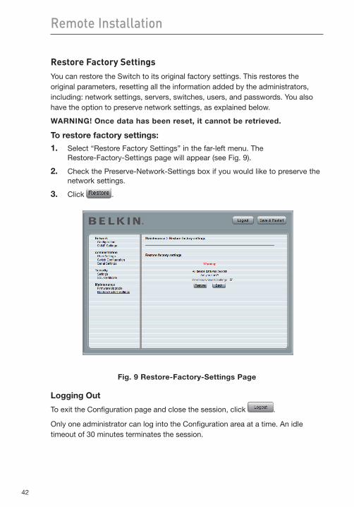
Restore Factory SettingsYou can restore the Switch to its original factory settings. This restores the original parameters, resetting all the information added by the administrators, including: network settings, servers, switches, users, and passwords. You also have the option to preserve network settings, as explained below.
WARNING! Once data has been reset, it cannot be retrieved.
To restore factory settings:
1. Select “Restore Factory Settings” in the far-left menu. The Restore-Factory-Settings page will appear (see Fig. 9).
2. Check the Preserve-Network-Settings box if you would like to preserve the network settings.
3. Click .
Fig. 9 Restore-Factory-Settings Page
Logging Out
To exit the Configuration page and close the session, click .
Only one administrator can log into the Configuration area at a time. An idle timeout of 30 minutes terminates the session.
43
1
2
3
4
5
6
7
8
9
10
section Using the Switch from a Remote Console
Starting a Remote Session
To start a remote session:1. At a client computer, open Internet Explorer or Firefox web browser and
type the IP Device’s IP address (https:// IP address).
2. When the Login screen appears, type in your user name and password, and click . By default, the user name is “admin” and the password is “SMBremote” (both are case-sensitive).
3. If it is your first time connecting, you will be prompted to install the Belkin certificate and the Microsoft ActiveX control. You must have administrator privileges on your client computer to install the ActiveX control.
4. The screen of the currently selected server on the Switch will appear. The quick-access toolbar will also appear on the right side of the screen.
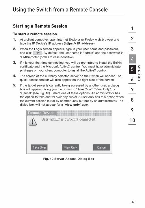
5. If the target server is currently being accessed by another user, a dialog box will appear, giving you the option to “Take Over”, “View Only”, or “Cancel” (see Fig. 10). Select one of these options. An administrator has the option to take control over any server. A user only has this option when the current session is run by another user, but not by an administrator. The dialog box will not appear for a “view only” user.
Fig. 10 Server-Access Dialog Box
44
Using the Switch from a Remote Console
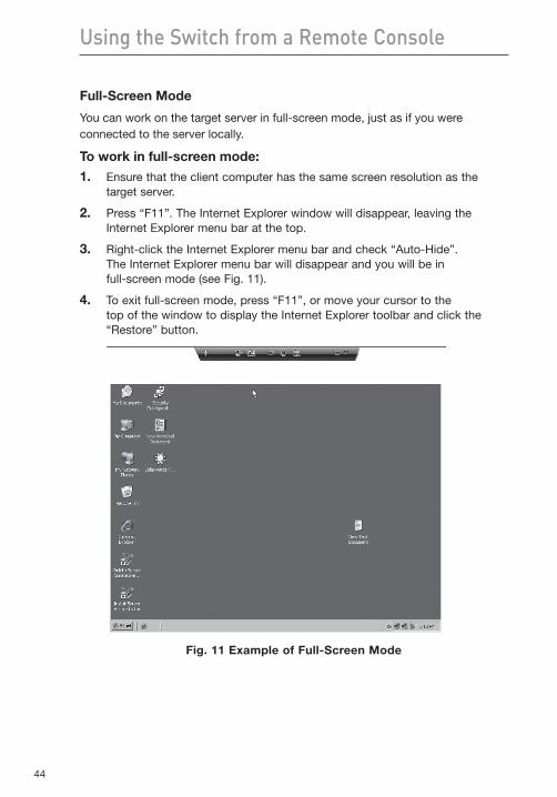
Full-Screen Mode
You can work on the target server in full-screen mode, just as if you were connected to the server locally.
To work in full-screen mode:
1. Ensure that the client computer has the same screen resolution as the target server.
2. Press “F11”. The Internet Explorer window will disappear, leaving the Internet Explorer menu bar at the top.
3. Right-click the Internet Explorer menu bar and check “Auto-Hide”. The Internet Explorer menu bar will disappear and you will be in full-screen mode (see Fig. 11).
4. To exit full-screen mode, press “F11”, or move your cursor to the top of the window to display the Internet Explorer toolbar and click the “Restore” button.
Fig. 11 Example of Full-Screen Mode
45
1
2
3
4
5
6
7
8
9
10
section Using the Switch from a Remote Console
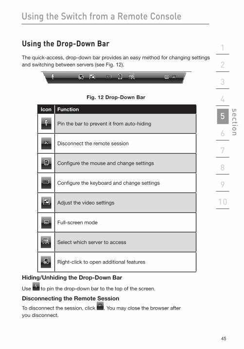
UsingtheDrop-DownBar
The quick-access, drop-down bar provides an easy method for changing settings and switching between servers (see Fig. 12).
Fig. 12 Drop-Down Bar
Icon Function
Pin the bar to prevent it from auto-hiding
Disconnect the remote session
Configure the mouse and change settings
Configure the keyboard and change settings
Adjust the video settings
Full-screen mode
Select which server to access
Right-click to open additional features
Hiding/Unhiding the Drop-Down Bar
Use to pin the drop-down bar to the top of the screen.
Disconnecting the Remote Session
To disconnect the session, click . You may close the browser after you disconnect.
46
Using the Switch from a Remote Console
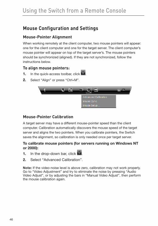
Mouse Configuration and Settings
Mouse-Pointer AlignmentWhen working remotely at the client computer, two mouse pointers will appear: one for the client computer and one for the target server. The client computer’s mouse pointer will appear on top of the target server’s. The mouse pointers should be synchronized (aligned). If they are not synchronized, follow the instructions below.
Toalignmousepointers:1. In the quick-access toolbar, click .
2. Select “Align” or press “Ctrl+M”.
Mouse-Pointer CalibrationA target server may have a different mouse-pointer speed than the client computer. Calibration automatically discovers the mouse speed of the target server and aligns the two pointers. When you calibrate pointers, the Switch saves the alignment, so calibration is only needed once per target server.
To calibrate mouse pointers (for servers running on Windows NT or 2000):
1. In the drop-down bar, click .
2. Select “Advanced Calibration”.
Note: If the video-noise level is above zero, calibration may not work properly. Go to “Video Adjustment” and try to eliminate the noise by pressing “Audio Video Adjust”, or by adjusting the bars in “Manual Video Adjust”, then perform the mouse calibration again.
47
1
2
3
4
5
6
7
8
9
10
section Using the Switch from a Remote Console
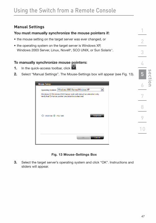
Manual SettingsYou must manually synchronize the mouse pointers if:
•themousesettingonthetargetserverwaseverchanged,or
• theoperatingsystemonthetargetserverisWindowsXP, Windows 2003 Server, Linux, Novell®, SCO UNIX, or Sun Solaris™.
To manually synchronize mouse pointers:
1. In the quick-access toolbar, click .
2. Select “Manual Settings”. The Mouse-Settings box will appear (see Fig. 13).
Fig. 13 Mouse-Settings Box
3. Select the target server’s operating system and click “OK”. Instructions and sliders will appear.
48
Using the Switch from a Remote Console
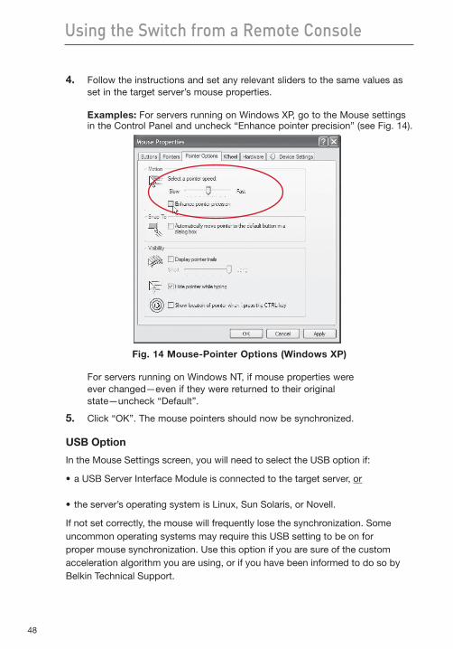
4. Follow the instructions and set any relevant sliders to the same values as set in the target server’s mouse properties.
Examples: For servers running on Windows XP, go to the Mouse settings in the Control Panel and uncheck “Enhance pointer precision” (see Fig. 14).
Fig. 14 Mouse-Pointer Options (Windows XP)
For servers running on Windows NT, if mouse properties were ever changed—even if they were returned to their original state—uncheck “Default”.
5. Click “OK”. The mouse pointers should now be synchronized.
USB Option
In the Mouse Settings screen, you will need to select the USB option if:
•aUSBServerInterfaceModuleisconnectedtothetargetserver,or
•theserver’soperatingsystemisLinux,SunSolaris,orNovell.
If not set correctly, the mouse will frequently lose the synchronization. Some uncommon operating systems may require this USB setting to be on for proper mouse synchronization. Use this option if you are sure of the custom acceleration algorithm you are using, or if you have been informed to do so by Belkin Technical Support.
49
1
2
3
4
5
6
7
8
9
10
section Using the Switch from a Remote Console
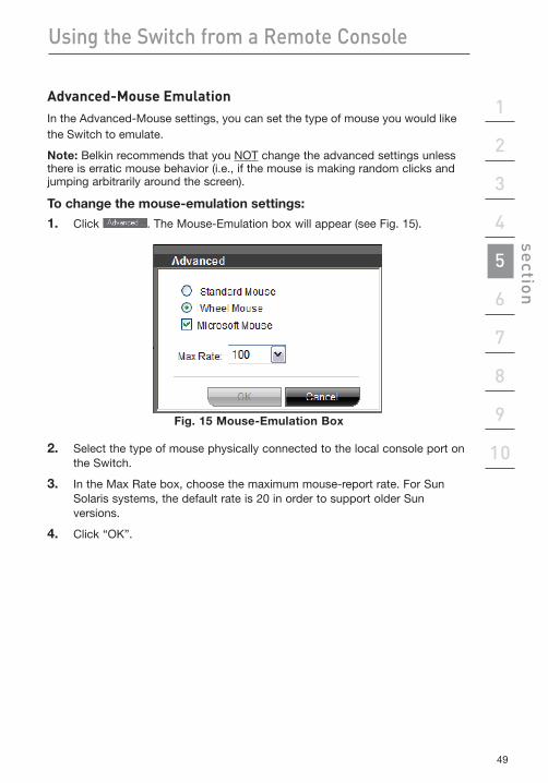
Advanced-MouseEmulationIn the Advanced-Mouse settings, you can set the type of mouse you would like the Switch to emulate.
Note: Belkin recommends that you NOT change the advanced settings unless there is erratic mouse behavior (i.e., if the mouse is making random clicks and jumping arbitrarily around the screen).
To change the mouse-emulation settings:
1. Click . The Mouse-Emulation box will appear (see Fig. 15).
Fig. 15 Mouse-Emulation Box
2. Select the type of mouse physically connected to the local console port on the Switch.
3. In the Max Rate box, choose the maximum mouse-report rate. For Sun Solaris systems, the default rate is 20 in order to support older Sun versions.
4. Click “OK”.
50
Using the Switch from a Remote Console
Keyboard Configuration and Settings
You can define and transmit a keyboard sequence directly to the target server, without affecting the client computer.
To transmit a keyboard sequence:
1. In the quick-access toolbar, click .
2. Select a key sequence to transmit to the target server.
For example, if you select the “Ctrl-Alt-Del” keyboard sequence for the target server, it will allow you to initiate the server’s shutdown/login process from your client computer.
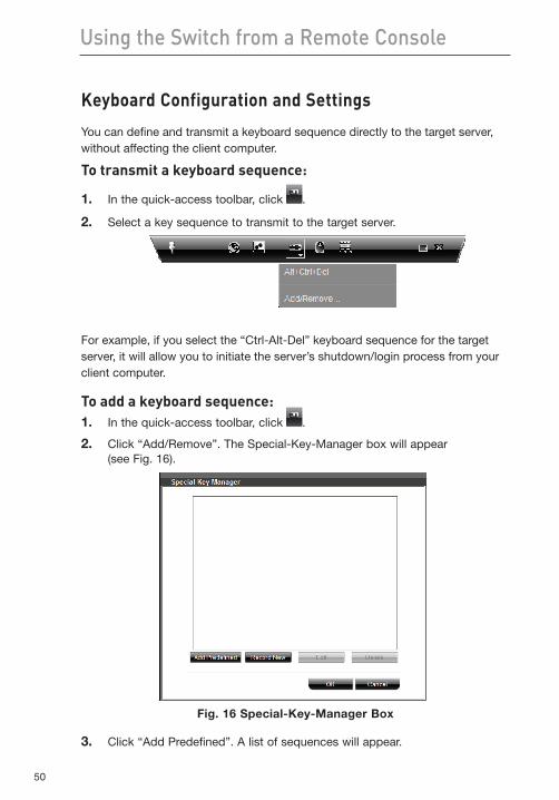
To add a keyboard sequence:1. In the quick-access toolbar, click .
2. Click “Add/Remove”. The Special-Key-Manager box will appear (see Fig. 16).
Fig. 16 Special-Key-Manager Box
3. Click “Add Predefined”. A list of sequences will appear.
51
1
2
3
4
5
6
7
8
9
10
section Using the Switch from a Remote Console
4. Select the desired sequence and click “OK”. The sequence will appear in the Special-Key-Manager box.
5. Click “OK”. The sequence will now appear in the Keyboard-Key-Sequence list.
To record a keyboard sequence:
1. In the quick-access toolbar, click .
2. Click “Add/Remove”. The Special-Key-Manager box will appear.
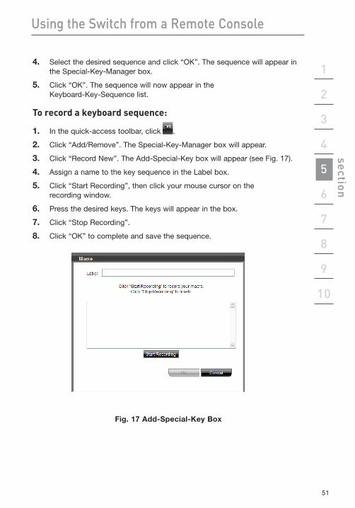
3. Click “Record New”. The Add-Special-Key box will appear (see Fig. 17).
4. Assign a name to the key sequence in the Label box.
5. Click “Start Recording”, then click your mouse cursor on the recording window.
6. Press the desired keys. The keys will appear in the box.
7. Click “Stop Recording”.
8. Click “OK” to complete and save the sequence.
Fig. 17 Add-Special-Key Box
52
Using the Switch from a Remote Console
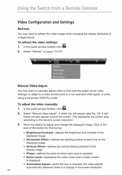
Video Configuration and Settings
RefreshYou may need to refresh the video image when changing the display attributes of a target server.
To refresh the video settings:
1. In the quick-access toolbar, click .
2. Select “Refresh” or press “Crl+R”.
Manual Video AdjustYou may want to manually adjust video to fine-tune the target-server video settings, to adapt to a noisy environment or a non-standard VGA signal, or when using a full-screen DOS/CLI mode.
To adjust the video manually:
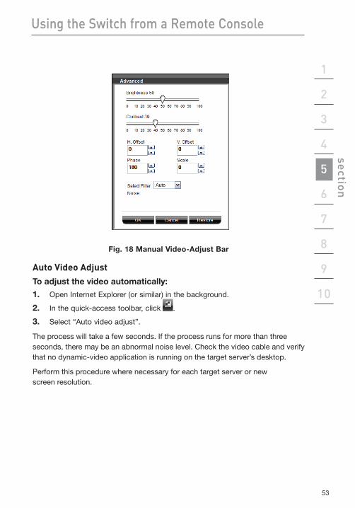
1. In the quick-access toolbar, click .
2. Select “Manual video adjust”. A slider bar will appear (see Fig. 18). A red frame will also appear around the screen. This represents the screen area according to the server’s screen resolution.
3. Move the sliders to adjust and change the displayed image. Click in the area of the sliders for fine-tuning.
• Brightness/Contrast—� adjusts the brightness and contrast of the displayed image
• HorizontalOffset—�defines the starting position of each line on the displayed image
• VerticalOffset—�defines the vertical starting position of the display image
• Phase—�defines the point at which each pixel is sampled• NoiseLevel—�represents the video noise when a static screen
is displayed• AutomatedAdjust—�when this box is checked, the video adjusts
automatically whenever there is a change in the screen resolution.
53
1
2
3
4
5
6
7
8
9
10
section Using the Switch from a Remote Console
Fig. 18 Manual Video-Adjust Bar
Auto Video AdjustTo adjust the video automatically:
1. Open Internet Explorer (or similar) in the background.
2. In the quick-access toolbar, click .
3. Select “Auto video adjust”.
The process will take a few seconds. If the process runs for more than three seconds, there may be an abnormal noise level. Check the video cable and verify that no dynamic-video application is running on the target server’s desktop.
Perform this procedure where necessary for each target server or new screen resolution.
54
Using the Switch from a Remote Console
PerformanceSettings(Bandwidth)
You can adjust the bandwidth settings on the Switch to give you the desired compression and color-support levels for your remote sessions.
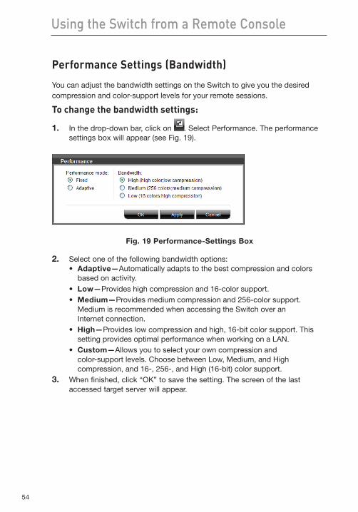
To change the bandwidth settings:
1. In the drop-down bar, click on . Select Performance. The performance settings box will appear (see Fig. 19).
Fig. 19 Performance-Settings Box
2. Select one of the following bandwidth options:• Adaptive—�Automatically adapts to the best compression and colors
based on activity.• Low—�Provides high compression and 16-color support.• Medium—�Provides medium compression and 256-color support.
Medium is recommended when accessing the Switch over an Internet connection.
• High—�Provides low compression and high, 16-bit color support. This setting provides optimal performance when working on a LAN.
• Custom—�Allows you to select your own compression and color-support levels. Choose between Low, Medium, and High compression, and 16-, 256-, and High (16-bit) color support.
3. When finished, click “OK” to save the setting. The screen of the last accessed target server will appear.
55
1
2
3
4
5
6
7
8
9
10
section Using the Switch from a Remote Console
Selecting a Server
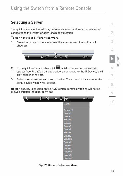
The quick-access toolbar allows you to easily select and switch to any server connected to the Switch or daisy-chain configuration.
To connect to a different server:1. Move the cursor to the area above the video screen; the toolbar will
show up.
2. In the quick-access toolbar, click . A list of connected servers will appear (see Fig. 20). If a serial device is connected to the IP Device, it will also appear on the list.
3. Select the desired server or serial device. The screen of the server or the serial-device window will appear.
Note: If security is enabled on the KVM switch, remote switching will not be allowed through the drop-down bar.
Fig. 20 Server-Selection Menu
56
Using the Switch from a Remote Console
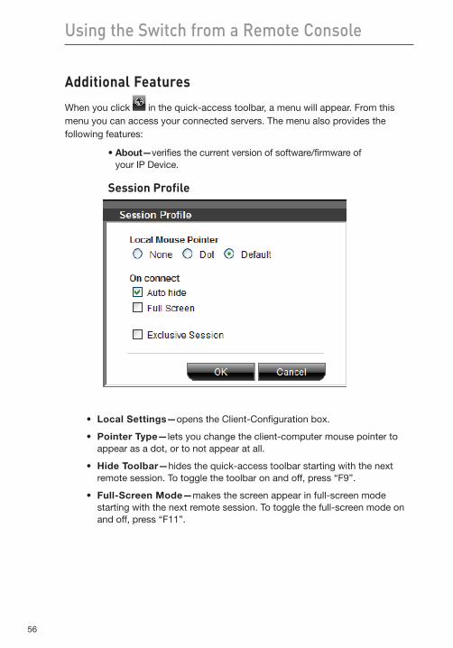
Additional Features
When you click in the quick-access toolbar, a menu will appear. From this menu you can access your connected servers. The menu also provides the following features:
•About—�verifies the current version of software/firmware of your IP Device.
Session Profile
• LocalSettings—�opens the Client-Configuration box.
• PointerType—�lets you change the client-computer mouse pointer to appear as a dot, or to not appear at all.
• HideToolbar—�hides the quick-access toolbar starting with the next remote session. To toggle the toolbar on and off, press “F9”.
• Full-ScreenMode—�makes the screen appear in full-screen mode starting with the next remote session. To toggle the full-screen mode on and off, press “F11”.
57
1
2
3
4
5
6
7
8
9
10
section
57
Using the Switch from a Remote Console
RestoringFactoryDefaults
The “Restore Factory Settings” section below explains how to restore factory settings from the web interface. When you cannot access the system (you have forgotten the user name, IP address, or password), you can restore factory defaults from the Switch.
To restore factory defaults:1. Press and hold down the “Go-Local” button on the back of the IP Device
for five seconds while powering up the IP Device. The IP Device will boot up in safe mode.
2. Wait 30 seconds for the IP Device to reboot.
3. If a DHCP server is available, the IP Device will pick up an IP address from it. If there is no DHCP server, the IP Device boots with static IP address: 192.168.2.155.
4. Log in with the default IP address of the unit: http://192.168.2.155/config. The blank login screen will appear (no background picture).
Note: Do not start the IP address with https.
4. Type in the following default user name and password (case-sensitive), and click “Login”. This user name and password only work immediately after the reset procedure described above.
5. Type in the following default user name and password (case-sensitive), and click “Login”. This user name and password only work immediately after the reset procedure described above.
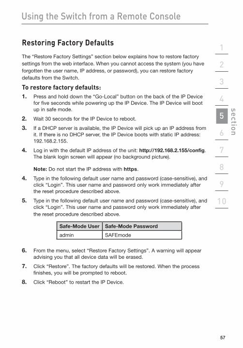
Safe-Mode User Safe-Mode Password
admin SAFEmode
6. From the menu, select “Restore Factory Settings”. A warning will appear advising you that all device data will be erased.
7. Click “Restore”. The factory defaults will be restored. When the process finishes, you will be prompted to reboot.
8. Click “Reboot” to restart the IP Device.
58
Using the Switch from a Local Console
Now that you have connected your console and servers to the Switch, it is ready for use. You can select connected servers by using either the front-panel port selectors, the On-Screen Display (OSD), or hot-key commands through the console keyboard. It takes approximately 1–2 seconds for the video signal to refresh after switching servers. Re-synchronization of the mouse and keyboard signals also occurs. This is normal operation and ensures that proper synchronization is established between the console and the connected servers.
Selecting a Server or BANK
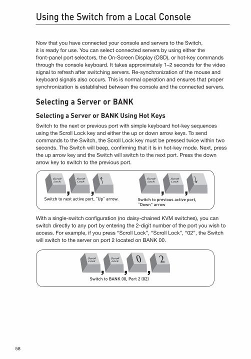
Selecting a Server or BANK Using Hot KeysSwitch to the next or previous port with simple keyboard hot-key sequences using the Scroll Lock key and either the up or down arrow keys. To send commands to the Switch, the Scroll Lock key must be pressed twice within two seconds. The Switch will beep, confirming that it is in hot-key mode. Next, press the up arrow key and the Switch will switch to the next port. Press the down arrow key to switch to the previous port.
Switch to previous active port, “Down” arrow
Switch to next active port, “Up” arrow.
With a single-switch configuration (no daisy-chained KVM switches), you can switch directly to any port by entering the 2-digit number of the port you wish to access. For example, if you press “Scroll Lock”, “Scroll Lock”, “02”, the Switch will switch to the server on port 2 located on BANK 00.
Switch to BANK 00, Port 2 (02)
59
1
2
3
4
5
6
7
8
9
10
section Using the Switch from a Local Console
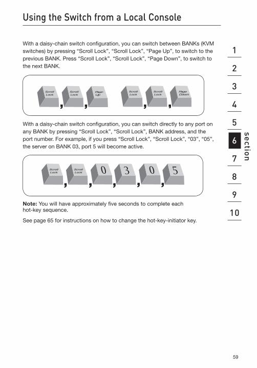
With a daisy-chain switch configuration, you can switch between BANKs (KVM switches) by pressing “Scroll Lock”, “Scroll Lock”, “Page Up”, to switch to the previous BANK. Press “Scroll Lock”, “Scroll Lock”, “Page Down”, to switch to the next BANK.
P a g e D o w n
P a g e U p
With a daisy-chain switch configuration, you can switch directly to any port on any BANK by pressing “Scroll Lock”, “Scroll Lock”, BANK address, and the port number. For example, if you press “Scroll Lock”, “Scroll Lock”, “03”, “05”, the server on BANK 03, port 5 will become active.
Note: You will have approximately five seconds to complete each hot-key sequence.
See page 65 for instructions on how to change the hot-key-initiator key.
60
Using the Switch from a Remote Console
Selecting a Server Using Port SelectorsYou can directly select which server you wish to control by pressing the port selector next to the corresponding port. The LED will illuminate to indicate the port is currently selected. If you are installing multiple KVM Switches that are daisy-chained, use the BANK scroll keys located on the front panel of the primary KVM Switch to access other servers that are connected to the secondary KVM Switches.
Selecting a BANK Using Scroll ButtonsPressing the “BANK +” and “BANK –” scroll buttons on the primary KVM Switch will allow you to switch between the daisy-chained Switches. Pressing both buttons simultaneously will reset the Switch.
The “BANK +” button will take you to the next BANK. For example, when you are at the primary switch (BANK 00) and want to check servers on BANK 02, pressing the “BANK +” button will take you to BANK 02. As a default, the first active server will be displayed on the console monitor. Use the port selectors to go to the desired server on BANK 02.
The “BANK –” button will take you to the previous BANK (for example, when you are at BANK 02 and want to check servers in BANK 01). Pressing the “BANK –” button will take you to BANK 01. As a default, the first active server will be displayed on the console monitor. Use the port selectors to go to the desired server on BANK 01.
61
1
2
3
4
5
6
7
8
9
10
section Using the Switch from a Remote Console
AutoScan Mode
The AutoScan feature allows you to set your Switch to scan and monitor the activities of all connected servers one by one. The Switch remains on one server for a preset number of seconds, before switching to the next server. The time interval allotted for each server can be defined or adjusted through the OSD menu (see the “Scan Time” section).
When the Switch is in AutoScan mode, it is also in view-only mode. This means that input from the console (keyboard and mouse) will not be transmitted to the server in focus. Cancel AutoScan to regain control of the server.
To activate the AutoScan function, press the “AutoScan” button on the Switch. You can also activate AutoScan on your keyboard by pressing “Scroll Lock”, “Scroll Lock”, space bar, “F4”.
To disable AutoScan, press any button on the front panel or any key on the keyboard.
Note: There is no mouse or keyboard control in AutoScan mode. This is necessary to prevent data and synchronization errors. If the user is using the mouse or keyboard when the Switch is switching between ports, data flow may become interrupted and could result in erratic mouse movement and/or wrong-character input when using the keyboard.
62
Using the Switch from a Remote Console
On-ScreenDisplay(OSD)
The OSD allows you to switch servers, assign names to your servers, enable and disable the AutoScan feature, set the desired scan-time interval for AutoScan, enable the password security feature, and program hot keys. To access the OSD menu, press “Scroll Lock”, “Scroll Lock”, and the space bar. Immediately, the OSD overlay screen will appear. The superimposed menu screen is generated by the Switch, and does not affect the function of your server, operating system, or software function. This OSD and all its functions are recommended for local-console use only.
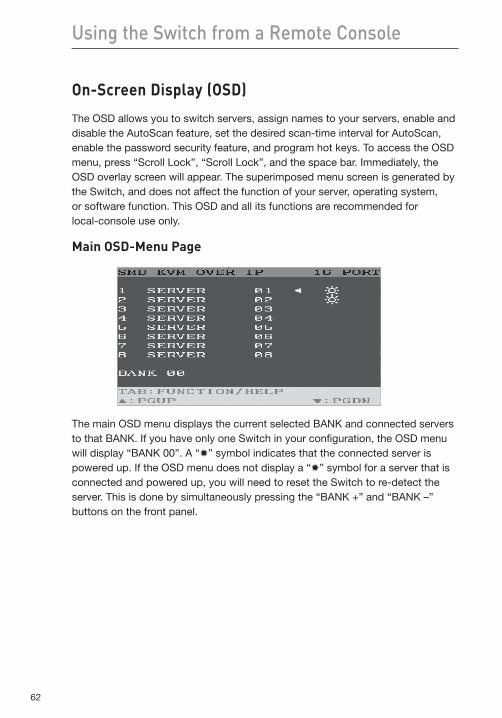
MainOSD-MenuPage
The main OSD menu displays the current selected BANK and connected servers to that BANK. If you have only one Switch in your configuration, the OSD menu will display “BANK 00”. A “✹” symbol indicates that the connected server is powered up. If the OSD menu does not display a “✹” symbol for a server that is connected and powered up, you will need to reset the Switch to re-detect the server. This is done by simultaneously pressing the “BANK +” and “BANK –” buttons on the front panel.
63
1
2
3
4
5
6
7
8
9
10
section Using the Switch from a Remote Console
OSD-Menu Keyboard Commands
Command Function
èê Navigate to different servers in the same BANK
Page Up/Page Down Select next or previous BANK
Insert Highlight server name for editing
Enter Switch servers
Tab Open the Function/Help page
Esc Exit the OSD
To switch servers using the main OSD menu, use the arrow keys on your keyboard to navigate to the desired server and press the “ENTER” key. A “!” symbol indicates which server is currently being accessed on your console.
To change the name of a server, use the arrow keys to navigate to the desired server, press the “Insert” key, type in the new name, and press “ENTER” to save the entry. You may use up to 15 characters for each server name.
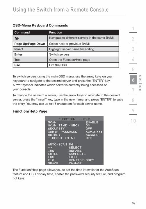
Function/HelpPage
The Function/Help page allows you to set the time intervals for the AutoScan feature and OSD display time, enable the password security feature, and program hot keys.
64
Using the Switch from a Remote Console
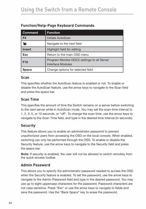
Function/Help-PageKeyboardCommands
Command Function
F4 Initiate AutoScan
èê Navigate to the next field
Insert Highlight field for editing
Esc Return to the main OSD menu
F10Program Monitor-DDC2 settings to all Server Interface Modules
Space Change options for selected field
ScanThis specifies whether the AutoScan feature is enabled or not. To enable or disable the AutoScan feature, use the arrow keys to navigate to the Scan field and press the space bar.
Scan TimeThis specifies the amount of time the Switch remains on a server before switching to the next server while in AutoScan mode. You may set the scan-time interval to 1, 2, 3, 5, or 10 seconds, or “off”. To change the scan time, use the arrow keys to navigate to the Scan Time field, and type in the desired time interval (in seconds).
SecurityThis feature allows you to enable an administrator password to prevent unauthorized users from accessing the OSD on the local console. When enabled, switching can only be performed through the OSD. To enable or disable the Security feature, use the arrow keys to navigate to the Security field and press the space bar.
Note: If security is enabled, the user will not be allowed to switch remotely from the quick-access toolbar.
Admin PasswordThis allows you to specify the administrator password needed to access the OSD when the Security feature is enabled. To set the password, use the arrow keys to navigate to the Admin-Password field and type in the desired password. You may use up to eight uppercase characters for the password. Password characters are not case-sensitive. Press “Esc” or use the arrow keys to navigate to fields and save the password. Use the “Back Space” key to erase the password.
65
1
2
3
4
5
6
7
8
9
10
section Using the Switch from a Remote Console
Hot KeyThis allows you to select which key will be used to initiate hot-key commands. You have four options to choose from: “Scroll Lock”, “Print Screen”, “Ctrl”, and “F12”. The default key for all hot-key commands is “Scroll Lock” (see “Hot-Key-Command Shortcuts” on next page). To designate a different key to initiate hot-key commands, use the arrow keys to navigate to the Hot-Key field, press the space bar until the preferred key is found, and press “Enter” to save the entry.
Note: If you change the hot key to “Print Screen”, “Ctrl”, or “F12”, you will need to upload a new switch-definition file (SDF) to change servers from a remote session. See page 37 for more details.
TimeoutThis specifies the amount of time that can elapse before the administrator will be locked out of the KVM Switch (and connected servers) due to user inactivity. To regain access to the KVM Switch after timeout, simply reenter the admin password in the login box. The Timeout feature is only available if the Security feature is enabled. You may set the time intervals to anywhere between 1 and 99 minutes. To change the time interval, use the arrow keys to navigate, type the desired time interval, and press “Enter” to save the entry. If you disable the Security feature, the Timeout feature will be turned off automatically.
Note: If there are secondary KVM Switches connected, and the AutoScan time and timeout settings are set on the primary KVM Switch, the settings will also apply to all secondary KVM Switches.
Monitor-DDC2FeatureThis feature allows the console monitor to send information to the server’s video card about its properties, such as maximum resolution and color depth supported. The video card will then adjust the monitor’s settings accordingly. This enables your monitor to use its optimal settings for every server connected to your Switch. To read the DDC2 information from the monitor and program it to all connected Server Interface Modules, press “F10”. Every time you change the monitor, you will need to press “F10” again to program the new DDC information to the Server Interface Modules. We recommend you perform this operation on a local console only.

66
Using the Switch from a Remote Console
Hot-Key-Command Shortcuts
Below is a complete list of hot-key commands that can be used for your Switch:
Command Function
Scroll Lock, Scroll Lock, è Switch to PREVIOUS ACTIVE port
Scroll Lock, Scroll Lock, ê Switch to NEXT ACTIVE port
Scroll Lock, Scroll Lock, Page Up
Switch to PREVIOUS BANK (By default, selects first active port on the BANK)
Scroll Lock, Scroll Lock, Page Down
Switch to NEXT BANK (By default, selects first active port on the BANK)
Scroll Lock, Scroll Lock, Y Directly switches to PORT Y on BANK 00 (single-switch configuration) (Y=01 to 16)
Scroll Lock, Scroll Lock, Y, X
Directly switches to PORT Y on BANK X (daisy-chain configuration) (X=00 to 15), (Y=01 to 16)
Scroll Lock, Scroll Lock, Space Bar, F10 Monitor DDC2 (identifies monitor settings)
Scroll Lock, Scroll Lock, Space Bar Activate OSD
Scroll Lock, Scroll Lock, F4 Enable AutoScan mode (refer to AutoScan button)
Note: You will have approximately five seconds to complete each hot-key sequence.
67
1
2
3
4
5
6
7
8
9
10
section
67
Using the Switch from a Remote Console
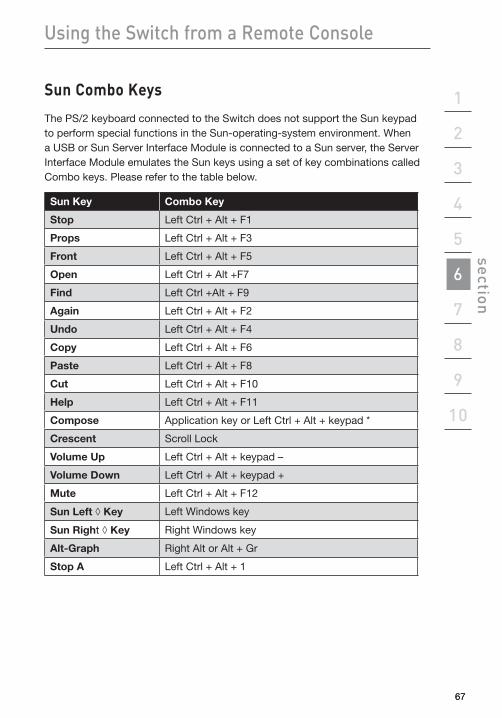
Sun Combo Keys
The PS/2 keyboard connected to the Switch does not support the Sun keypad to perform special functions in the Sun-operating-system environment. When a USB or Sun Server Interface Module is connected to a Sun server, the Server Interface Module emulates the Sun keys using a set of key combinations called Combo keys. Please refer to the table below.
Sun Key Combo Key
Stop Left Ctrl + Alt + F1
Props Left Ctrl + Alt + F3
Front Left Ctrl + Alt + F5
Open Left Ctrl + Alt +F7
Find Left Ctrl +Alt + F9
Again Left Ctrl + Alt + F2
Undo Left Ctrl + Alt + F4
Copy Left Ctrl + Alt + F6
Paste Left Ctrl + Alt + F8
Cut Left Ctrl + Alt + F10
Help Left Ctrl + Alt + F11
Compose Application key or Left Ctrl + Alt + keypad *
Crescent Scroll Lock
Volume Up Left Ctrl + Alt + keypad –
Volume Down Left Ctrl + Alt + keypad +
Mute Left Ctrl + Alt + F12
Sun Left ◊ Key Left Windows key
Sun Right ◊ Key Right Windows key
Alt-Graph Right Alt or Alt + Gr
Stop A Left Ctrl + Alt + 1
68
Using the Switch from a Remote Console
UpdatingFirmware
The Switch features flash-upgradeable firmware to ensure compatibility with the latest devices and servers. Firmware upgrades are free for the life of your Switch.
To update your firmware, download the appropriate firmware file and utility from www.belkin.com/support/. The utility will guide you through the process of updating the firmware on your Switch.
Warning: We strongly recommend that you update your firmware only if you are experiencing mouse and keyboard problems with your Switch, as reconfiguring software may lead to unexpected operational problems. Please contact Belkin Technical Support if you need assistance.
6969
1
2
3
4
5
6
7
8
9
10
section Frequently Asked Questions
WhatoperatingsystemsdoestheSwitchsupport? The Switch will support operating systems that run on a PS/2 or USB
platform. Operating systems include, but are not limited to, DOS; Windows NT, 2000, Server 2003, Server 2008, XP, Vista, Windows 7; Sun; Solaris; Novell; and Linux.
DoestheSwitchsupportMicrosoftIntelliMouse®? The Switch supports mice from Microsoft, Logitech®, Kensington®, etc., and
Belkin. Please contact Belkin Technical Support for compatibility issues you may experience.
How does the Switch allow the user to switch betweenports? The Switch supports three methods of port selection. The user can select
servers using specially designated keyboard hot keys, through the On-Screen Display (OSD), or can independently access the desired port by pushing the direct-access port selectors.
HowfarcantheserverbefromtheSwitch? The Switch can be placed up to 100 feet (30m) away from
your server.
Whatisthemaximumvideoresolutionthatthe Switchsupports? The advanced video circuit in the Switch supports a
maximum resolution of up to 1600x1200 @ 75Hz. Increasing the cable length from your Switch to your servers will result in lower resolution support.
DoIhavetoinstallanysoftwaretousetheSwitch? No, the Switch does not require any drivers or software to be installed in your
servers. Simply connect all your servers to the Switch using Server Interface Modules, and then attach one keyboard, monitor, and mouse to the console port, and it is ready for use.
CanIusetheSwitchonmySunserverthatsupportsUSB? Yes, the Switch works with any USB-capable server.
Frequently Asked Questions
70
Frequently Asked Questions
DoestheSwitchsupportLinux? Yes, the Switch works with Red Hat and other Linux distributions configured
for PS/2 or USB support.
WhatcommunicationportsdoestheSwitchusesoitcanbeaccessedremotely? Five ports have to be open to remotely connect to the Switch. Ports 80 and
443 are used for standard web communication. Three consecutive ports are used to send the remote video. These can be user-defined. By default, ports 900, 901, and 902 are used.
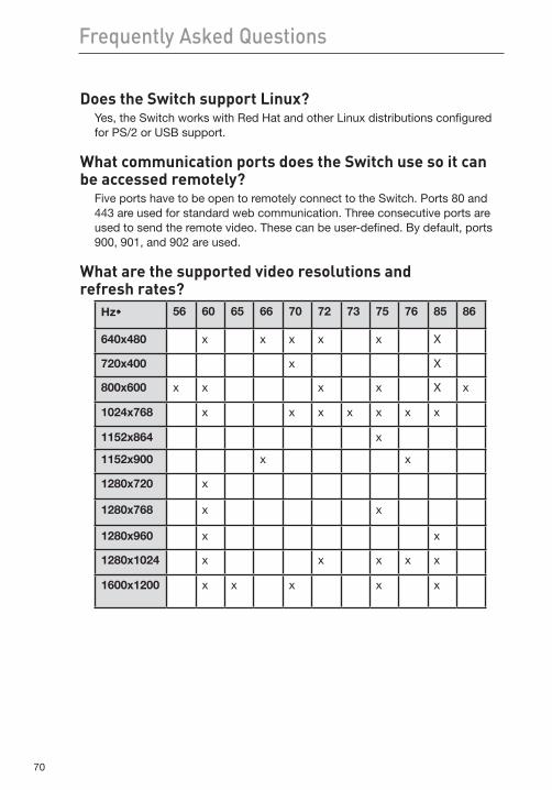
Whatarethesupportedvideoresolutionsand refreshrates?
Hz¶ 56 60 65 66 70 72 73 75 76 85 86
640x480 x x x x x X
720x400 x X
800x600 x x x x X x
1024x768 x x x x x x x
1152x864 x
1152x900 x x
1280x720 x
1280x768 x x
1280x960 x x
1280x1024 x x x x x
1600x1200 x x x x x
71
1
2
3
4
5
6
7
8
9
10
section Troubleshooting
Local Console
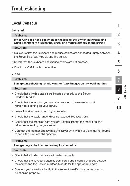
GeneralProblem:My server does not boot when connected to the Switch but works fine when I connect the keyboard, video, and mouse directly to the server.
Solution:
• Makesurethatthekeyboardandmousecablesareconnectedtightlybetweenthe Server Interface Module and the server.
•Checkthatthekeyboardandmousecablesarenotcrossed.
•ChecktheCAT5cableconnection.
VideoProblem:I am getting ghosting, shadowing, or fuzzy images on my local monitor.
Solution:
• Check that all video cables are inserted properly to the Server Interface Module.
• Check that the monitor you are using supports the resolution and refresh-rate setting on your server.
• Lower the video resolution of your monitor.
• Check that the cable length does not exceed 100 feet (30m).
• Check that the graphics card you are using supports the resolution and refresh-rate setting on your server.
• Connect the monitor directly into the server with which you are having trouble to see if the problem still appears.
Problem:I am getting a black screen on my local monitor.
Solution:
• Check that all video cables are inserted properly.
• Check that the keyboard cable is connected and inserted properly between the server and the Server Interface Module for the appropriate port.
• Connect your monitor directly to the server to verify that your monitor is functioning properly.
Troubleshooting
72
Troubleshooting
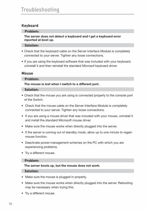
KeyboardProblem:The server does not detect a keyboard and I get a keyboard error reported at boot up.
Solution:
•CheckthatthekeyboardcableontheServerInterfaceModuleiscompletelyconnected to your server. Tighten any loose connections.
•Ifyouareusingthekeyboardsoftwarethatwasincludedwithyourkeyboard,uninstall it and then reinstall the standard Microsof keyboard driver.
MouseProblem:The mouse is lost when I switch to a different port.
Solution:
•Checkthatthemouseyouareusingisconnectedproperlytotheconsoleportof the Switch.
•CheckthatthemousecableontheServerInterfaceModuleiscompletelyconnected to your server. Tighten any loose connections.
•Ifyouareusingamousedriverthatwasincludedwithyourmouse,uninstallitand install the standard Microsoft mouse driver.
•Makesurethemouseworkswhendirectlypluggedintotheserver.
• Iftheserveriscomingoutofstandbymode,allowuptooneminutetoregainmouse function.
•Deactivatepower-managementschemesonthePCwithwhichyouareexperiencing problems.
•Tryadifferentmouse.
Problem:The server boots up, but the mouse does not work.
Solution:
•Makesurethemouseispluggedinproperly.
• Makesurethemouseworkswhendirectlypluggedintotheserver.Rebootingmay be necessary when trying this.
•Tryadifferentmouse.
73
1
2
3
4
5
6
7
8
9
10
section
73
Troubleshooting
Problem:When I switch from one port to another, mouse movement is completely erratic.
Solution:
•Makesureyoudonothavemorethanonemousedriverinstalled.Make sure that the driver is either for a standard PS/2 mouse or a Microsoft server-compatible PS/2 mouse.
•MakesureyoudonothaveanymousedriversloadedinyourConfigureSYSor AUTOEXEC.BAT files.
•Avoidmovingthemouseorpressingthemousebuttonwhenswitchingportson the Switch.
•Stopmovingthemouse,waitforfiveseconds,andthenmovethe mouse again. The Server Interface Module will synchronize the mouse movement automatically.
USBProblem:I am connecting the USB Server Interface Module to my USB server and my keyboard and mouse do not work.
Solution:
•PriortoconnectingtheUSBServerInterfaceModule,makesurethattheHIDUSB driver is installed on each server. (To install the HID USB driver, connect a USB mouse and USB keyboard to the server. A Windows operating system should automatically install the drivers.)
74
Troubleshooting
Remote ConsoleProblem:The Remote console login page will not display on my browser.
Solution:
•VerifythatyouareusingMicrosoftInternetExplorer6.0,7.0,8.0 (in Compatibility View), Firefox 3.0.
•VerifythattheActiveXplug-inisinstalledandenabledforthewebbrowser.
• Afirewallmaypreventaccesstotheremoteconsole.Verifythatdefaultports900, 901, and 902 for both HTTP and HTTPS are open. If you have selected your own ports, verify that the three consecutive ports are open based on the first port number you selected.
Problem:The mouse does not sync after I align the mouse using the quick-access toolbar.
Solution:
•Inthequick-accesstoolbar,clickthe“mouse”iconandselect“ManualSettings”. Check that the correct operating system and mouse settings are selected. Refer to page 47.
•Usethequick-accesstoolbarandselect“Autovideoadjust”under“VideoSettings”. Refer to page 53.
Problem:I can’t switch to a different server using the server list on the quick-access toolbar.
Solution:
•MakesureyoudisablethesecurityfeatureinthelocalOSD.Refertopage64.
• IfyouhavechangedthehotkeyinthelocalOSD,makesuretouploadanew switch-definition file (SDF). Refer to page 37.
•MakesureyouhavenamedtheserverintheSwitch-Configurationpage.Referto page 36.
75
1
2
3
4
5
6
7
8
9
10
section Troubleshooting
Problem:The video quality is bad and/or grainy.
Solution:
•Usethequick-accesstoolbartorefreshthevideoscreen.
• Usethequick-accesstoolbarandselect“Automatedadjust”under“Manualvideo adjust”. Refer to page 52.
Problem:The video performance and/or mouse performance is slow.
Solution:
•Usethequick-accesstoolbartorefreshthevideoscreen.
• Usethequick-accesstoolbarandselect“Automatedadjust”under“Manualvideo adjust”. Refer to page 52.
Problem:I forgot my password. How can I reset the RIPM to factory defaults?
Solution:
•Refertothe“RestoringFactoryDefaults”sectiononpage57.
Problem:I changed the LAN settings to a static IP address, but I cannot get into the web interface through the new IP address.
Solution:
•Makesureyouuncheckthe“EnableDHCP”box.
• Checkwhetherthecomputeryouareusingtoaccessthewebinterfacehas an IP address in the same domain as the new IP address to which you set your Switch.
•Refreshyourbrowserorclearyourbrowser’scache.
76
glossary
The following definitions are used throughout this User Manual.
AutoScan: A mode of operation where the KVM switch scans from one port to another, on an ongoing basis, as configured by the user.
BANK: The address of a daisy-chained KVM switch (00–15), set by the DIP switch.
Client Computer: The computer being used to access the Switch remotely over a TCP/IP connection.
Console: The all-in-one term for the keyboard, video monitor, and mouse connected to a KVM switch.
Console Port: Receptors for the console to connect to the KVM switch.
Control: When discussing switching between ports, control means that the console is capable of sending input to the server. Control requires that the console also has focus on the port, and is viewing it.
DDC: Short for Display Data Channel, a VESA standard for communication between a monitor and a video adapter. Using DDC, a monitor can inform a computer’s video card about its properties, such as maximum resolution and color depth, to ensure that the user is presented with valid options for configuring the display.
DHCP: Dynamic Host Configuration Protocol. An Internet protocol that allows nodes to dynamically acquire (“lease”) network addresses for periods of time rather than having to pre-configure them. DHCP greatly simplifies the administration of large networks, and networks in which nodes frequently join and depart.
Daisy-Chain: A configuration of multiple KVM switches that are connected one to another in a series. A KVM-switch daisy-chain uses common settings to allow seamless, complex interactions between multiple consoles for control over many servers.
HID: Human Interface Device, the USB-device class that includes keyboards and mice.
77
1
2
3
4
5
6
7
8
9
10
section glossary
KVM: Literally “Keyboard Video Mouse”, this term refers to technology that allows two or more computers to be controlled by one keyboard, video monitor, and mouse; some switches that use KVM technology enable sharing of other peripherals such as audio speakers, microphones, and printers.
KVM Switch: A device that allows a user to access and control multiple servers from a single console. It has at least one console port and multiple server ports.
MAC: Media Access Control. In computer networking, a MAC address is a unique identifier attached to most forms of networking equipment.
OSD: On-Screen Display, a graphical user interface that can be used to control and configure the KVM switch.
Port: An interface receptor on a server through which you can attach a device or plug in a device cable.
Primary KVM Switch: The switch that is connected to the console and is set to BANK address 00.
SSL: Secure Sockets Layer. Cryptographic protocols that provide secure communications on the Internet for such things as email and Internet banking.
Secondary KVM Switch: Any KVM switch that is daisy-chained to the primary KVM switch and is set to BANK address 01–15 (and has no console connected).
TCP/IP: Transmission Control Protocol/Internet Protocol. Shorthand for the suite of rules defining the format devices use to communicate over the Internet.
Target Server: The server currently being accessed and controlled by the user from a local or remote console.

78
Information
FCC Statement
DeclarationofConformitywithFCCRules forElectromagneticCompatibility
We, Belkin International, Inc., of 501 West Walnut Street, Compton, CA 90220, declare under our sole responsibility that the products:
F1DP108G, F1DP116G, to which this declaration relates: Comply with Part 15 of the FCC Rules. Operation is subject to the following two conditions: (1)
this device may not cause harmful interference, and (2) this device must accept any interference received, including interference that may cause undesired operation.
CEDeclarationofConformityWe, Belkin International, Inc., declare under our sole responsibility that the products F1DP108G and F1DP116G, to which this declaration relates, are in conformity with Emissions Standard EN55022 Class A and with Immunity Standard EN55024, EN60950, EN61000-3-2, and EN61000-3-3.
ICESThis Class A digital apparatus complies with Canadian ICES-003. Cet appareil numérique de la classe A est conforme á la norme ICES-003 du Canada.
BelkinInternational,Inc.,Limited2-YearProductWarrantyWhatthiswarrantycovers.Belkin International, Inc. (“Belkin”) warrants to the original purchaser of this Belkin product that the product shall be free of defects in design, assembly, material, or workmanship.
Whattheperiodofcoverageis.Belkin warrants the Belkin product for two years.
Whatwillwedotocorrectproblems?Product Warranty.Belkin will repair or replace, at its option, any defective product free of charge (except for shipping charges for the product). Belkin reserves the right to discontinue any of its products without notice, and disclaims any limited warranty to repair or replace any such discontinued products. In the event that Belkin is unable to repair or replace the product (for example, because it has been discontinued), Belkin will offer either a refund or a credit toward the purchase of another product from Belkin.com in an amount equal to the purchase price of the product as evidenced on the original purchase receipt as discounted by its natural use.
Whatisnotcoveredbythiswarranty?All above warranties are null and void if the Belkin product is not provided to Belkin for inspection upon Belkin’s request at the sole expense of the
79
1
2
3
4
5
6
7
8
9
10
section Information
purchaser, or if Belkin determines that the Belkin product has been improperly installed, altered in any way, or tampered with. The Belkin Product Warranty does not protect against acts of God such as flood, lightning, earthquake, war, vandalism, theft, normal-use wear and tear, erosion, depletion, obsolescence, abuse, damage due to low voltage disturbances (i.e. brownouts or sags), non-authorized program, or system equipment modification or alteration.
How to get service.
To get service for your Belkin product you must take the following steps:
1. Contact Belkin International, Inc., at 501 W. Walnut St., Compton, CA 90220, Attn: Customer Service, or call (800)-223-5546, within 15 days of the Occurrence. Be prepared to provide the following information:
a. The part number of the Belkin product.
b. Where you purchased the product.
c. When you purchased the product.
d. Copy of original receipt.
2. Your Belkin Customer Service Representative will then instruct you on how to forward your receipt and Belkin product and how to proceed with your claim.
Belkin reserves the right to review the damaged Belkin product. All costs of shipping the Belkin product to Belkin for inspection shall be borne solely by the purchaser. If Belkin determines, in its sole discretion, that it is impractical to ship the damaged equipment to Belkin, Belkin may designate, in its sole discretion, an equipment repair facility to inspect and estimate the cost to repair such equipment. The cost, if any, of shipping the equipment to and from such repair facility and of such estimate shall be borne solely by the purchaser. Damaged equipment must remain available for inspection until the claim is finalized. Whenever claims are settled, Belkin reserves the right to be subrogated under any existing insurance policies the purchaser may have.
How state law relates to the warranty.THIS WARRANTY CONTAINS THE SOLE WARRANTY OF BELKIN. THERE ARE NO OTHER WARRANTIES, EXPRESSED OR, EXCEPT AS REQUIRED BY LAW, IMPLIED, INCLUDING THE IMPLIED WARRANTY OR CONDITION OF QUALITY, MERCHANTABILITY OR FITNESS FOR A PARTICULAR PURPOSE, AND SUCH IMPLIED WARRANTIES, IF ANY, ARE LIMITED IN DURATION TO THE TERM OF THIS WARRANTY.
Some states do not allow limitations on how long an implied warranty lasts, so the above limitations may not apply to you.
IN NO EVENT SHALL BELKIN BE LIABLE FOR INCIDENTAL, SPECIAL, DIRECT, INDIRECT, CONSEQUENTIAL OR MULTIPLE DAMAGES SUCH AS, BUT NOT LIMITED TO, LOST BUSINESS OR PROFITS ARISING OUT OF THE SALE OR USE OF ANY BELKIN PRODUCT, EVEN IF ADVISED OF THE POSSIBILITY OF SUCH DAMAGES.
80
1
2
3
4
5
6
7
8
9
10
section Information
This warranty gives you specific legal rights, and you may also have other rights, which may vary from state to state. Some states do not allow the exclusion or limitation of incidental, consequential, or other damages, so the above limitations may not apply to you.
P75215-A
Belkin Tech SupportUS: 800-223-5546 ext. 2263 310-898-1100 ext. 2263UK: 0845 607 77 87Australia: 1800 235 546New Zealand: 0800 235 546Singapore: 65 64857620 Europe: www.belkin.com/support
Belkin International, Inc.501 West Walnut StreetLos Angeles, CA 90220, USA310-898-1100310-898-1111 fax
Belkin Ltd.Express Business Park, Shipton WayRushden, NN10 6GL, United Kingdom+44 (0) 1933 35 2000+44 (0) 1933 31 2000 fax
Belkin B.V.Boeing Avenue 3331119 PH Schiphol-Rijk, The Netherlands+31 (0) 20 654 7300+31 (0) 20 654 7349 fax
Belkin Ltd.4 Pioneer AvenueTuggerah Business ParkTuggerah, NSW 2259, Australia+61 (0) 2 4350 4600+61 (0) 2 4350 4700 fax
© 2009 Belkin International, Inc.. All rights reserved. All trade names are registered trademarks of respective manufacturers listed. Mac is a trademark of Apple Inc., registered in the U.S. and other countries. Windows, Microsoft, NT, IntelliMouse, Internet Explorer, Windows Vista, and ActiveX are either registered trademarks or trademarks of Microsoft Corporation in the United States and/or other countries.
OmniView® SMB KVM-over-IP Switch