Embed Size (px)
Citation preview
1
Smart Wasp Pallet wrapping MachineManual
(please read carefully before using it)
Model:X300

2
Preface
Thank you for your purchase the equipment of Suzhou Auto-well Industrial AutomationCo.ltd.pallet wrapping machine X300 is suitable for packaging of bulk cargo containertransport and parts of the tray is extensively used in foreign trade and exports, the bottlecans, paper, hardware and electric appliance, plastic chemical industry, building materials,agricultural products, food and beverage, glass, animal husbandry, pharmaceutical andother industries.X300 is beautiful in appearance, easy to operate, simple maintenance, high energy
production to meet the production requirements of your company.In order to help your company to be faster and better use the advanced features of
our products, we will provide you with very detailed technical information.We are very willing to answer your questions if you have any confusion about our
products.Wishes you (your company) the business good
Before using the machine, please read this manual carefullyIf you have any technical changes without notice
3
Contents
1 the equipment delivery list....................................................................................... 52 equipment installation.............................................................................................. 5
1 .Preparation before installation.............................................................................51.1 area preparation.......................................................................................... 61.2 ground confirmation...................................................................................61.3 electrical confirmations ............................................................................ 61.4 equipment、tools and personnel requirements.......................................... 71.5 equipment loading and unloading and transporting................................... 71.6 General hardware fastening torque reference.............................................7
2. Installments......................................................................................................... 82.1 column installments ...............................................................................82.2 film carriage installation...........................................................................122.3 cutting film system installation.....................................错误!未定义书签。
2.4 alarm lamp installation.................................................错误!未定义书签。
2.5 film carriage power connection................................................................142.6 door installation........................................................................................202.7. tidy the wire ..........................................................................................222.8. top pressure deivce installation ............................................................ 22
3. test equipment...................................................................................................223.1 matters needing attention.............................................................................253.2 test preparation............................................................................................ 263.3 equipment pretest........................................................................................ 26
3 device parameters................................................................................................... 294 Equipment introduction..........................................................................................30
1. overview of devices and Applications...............................................................302 . introduction of the whole machine...................................................................323. column...............................................................................................................34
3.1 Lifting and moving group.........................................................................353.2 Lifting body..............................................................................................37
4. chass.................................................................................................................. 385. Film carriage......................................................................................................406. Electromagnet obstruct device.......................................................................... 44
5 Human computer interface..................................................................................... 481.Starting page.......................................................................................................482. automatic page...................................................................................................493. manual page.......................................................................................................514. parameter settings page..................................................................................... 52
4.1system parameter page.............................................................................. 544.5 I/O monitor page....................................................................................... 56
5.help page.............................................................................................................576 Operating procedures............................................................................................. 58

4
1.starting up...........................................................................................................582.Mounting film.....................................................................................................58
2.1 install membrane preparation................................................................... 582.2 install film.................................................................................................59
7 Common breakdown and elimination.................................................................... 601. indicator light doesn’t work.............................................................................. 602.turntable doesn’t work........................................................................................603. lifting device doesn’t work................................................................................604. stretch film is pulled off.................................................................................... 615. Electromagnet obstruct device doesn’t work.................................................... 616. cutting film system doesn’t work...................................................................... 61
8 Equipment safety precautions.............................................................................. 619 Circuit diagram.....................................................................................................6210 Machine safety ---------------------------------------------------------------------------6911 care and maintenance........................................................................................... 64
1. preparation before maintenance........................................................................ 642. maintenance points............................................................................................643.key maintenance instructions............................................................................. 65
Attached: Equipment Checklist....................................................................................681 daily check list....................................................................................................70

5
1 the equipment delivery listPlease note: after the opening of the control list items complete shipmentconfirmation
2 equipment installation
1 .Preparation before installation
Please read the entire installation section before you start, then step by step accordingto the instructions for installation.
Note:
A.complete each step and then proceed to the next step.
Serial no. name quantity remarks
1 Column 12 Chassis 13 Film Carriage 14 Cutting film 15 Cutting film fixed block 26 Alarm lamp 17 Six angle wrench 18 Door key 19 instructions 110 Remote control 111 M10*20Pan head bolts 2 For Column installation12 M10*20Inner six angle bolt / elastic / flat pad 2 For Column installation13 M6*20Inner six angle bolt / elastic / flat pad 4 For Alarm lamp installation14 Front door panel 315 Back door panel 3 The back door with lock plate16 The side plate (with lock, lock) 317 M8*25 Bolt 6 For cutting film system
installation18 M10*70 Bolt (all teeth) / nut 1 For Film carriage installation19 M10*50Bolt / elastic / flat pad 2 For Film carriage installation20 Tie 15 Connecting line

6
B.if the problems encountered in the installation process, please see the"troubleshooting", to help find it and solve problems.C.this equipment in the design process includes many security protectionmeasures, such as using the method of correctly is very safe when operation. If thereis no operation of equipment in accordance with the safety and the right way, it islikely to be the operator or other personnel near will cause potential safety hazard.During normal operation, attention should be paid to comply with all safety signs.Before the installation is complete, please don't put through power supply.
1.1 area preparation
This equipment installation is convenient, can be installed on the surface of the earth,can also be used in a pit and hand forklift/forklift truck product, at the same timespace need to meet the following requirements:A.The distance from film carriage lateral to the wall is not less than 600 mm;B.the distance from the back of columns to the wall is not less than 300 mm;
1.2 ground confirmation
The ground must be able to withstand the equipment weight to add on the equipmentthe maximum load capacity and the impulse capacity, namely request:Ground supporting capacity >= (680KG+ product weight) by 1.5 time.
watch out!Equipment around the ground must be flat, otherwise it may lead to wheel loadrotating difficult and sound bigger and may result in equipment damage.
1.3 electrical confirmationsThe system needs a special-purpose single-phase earth power source:220VAC; 10A; 50/60Hz,1PHAttention: The concrete electrical request, please refer the equipment marking label orthe electrical blueprint.
watch out!

7
A. using extension cord or any change may cause the circuit damage or affect theequipment performance, and can lead to he maintenance expiration.B. to avoid equipment damage, please check voltage of electrical drawings beforeboot device
1.4 equipment、tools and personnel requirements
A.a set of JSK pallet wrapping machineB.a set of tools (come with machine ), a set of forklift trucksC. mechanical/electrical technician 1 or 2, the use of personnel1
1.5 equipment loading and unloading and transporting
A.equipment main componentEquipment mainly includes chassis, turntable, column, film carriage , cutting
system and electromagnet blocking deviceB. loading and unloadingSmall parts, such as film carriage and so on removed from the car, in case of
falling damage when unloading bulkMain body (chassis and column) through using forklift to unload it and transport tothe installation place
1.6 General hardware fastening torque reference
Metric fastener torque chartFastener size Performance level torque(Nm)
6mm 8.8 14
8mm 8.8 2410mm 8.8 5412mm 10.9 102

8
2. Installments
Note: pictures and illustrations are for reference only, actual equipment may bedifferent.
A.using the forklift to move the equipment to the installment area and remove theouter packingB. takes out the stochastic tool, counting equipment is complete and Placed in orderdismantle lifting body and move it to the bottom of columns.
2.1 column installments
A. raises up the column (pay attention to security, when installing column)

9
B.the four sets of fasteners are fixed on the chassis frame (external two groups, Internal two groups).

10
C.after the column and the chassis fixed then insert the column down fixed axis, using M12 round nut to lock

11
D.connect chassis motor aviation plug and the column aviation plug
connect aviation plug
E.connect chassis aviation plug and the column aviation plug
connect aviation plug

12
2.2 film carriage installationA. lift the lifter then place the lifter fixed block beneath itB. film hanging from a pillar outside on the lifter (note that when the hookconnector through threaded hole below the hook plate to lift the body)
The film carriage is hung on the lifting.

13
C. using the corresponding bolt to fix the film carriage and the lifting body (note at the bottom of a group of tension film seat Tension bolt)
connecting wire through the hole tothe equipment
14
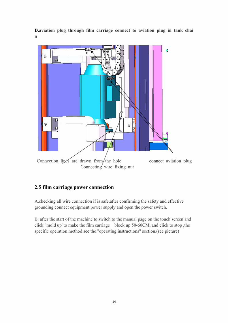
D.aviation plug through film carriage connect to aviation plug in tank chain
Connection lines are drawn from the hole connect aviation plugConnecting wire fixing nut
2.5 film carriage power connection
A.checking all wire connection if is safe,after confirming the safety and effectivegrounding connect equipment power supply and open the power switch.
B. after the start of the machine to switch to the manual page on the touch screen andclick "mold up"to make the film carriage block up 50-60CM, and click to stop ,thespecific operation method see the "operating instructions" section.(see picture)

15
C. remove the film carriage motor fastening nut assembly and set the drive chain, then fastening screw on the fastening nut by hand.

16
Picture 4.4
(3) The film base leads to quick connector and chain for quick connector
Screw install position
Screw install position
Screw install position
Film carriage cable pass this hole go to insideof machine

17
connection(see picture 4.5)The cable is fixed to the lifting body by a tie band.
Picture 4.5
4.2.4Film carriage power connection
⑴ Check the safety of all the wires of the equipment and confirm the
connection of the equipment.Turn on the power switch
⑵ After the machine starts, switch to the manual screen on the touch screen(see
“5、human-machine interface introduction”picture 5.3 manual interface),click
“rise”lift the lifting body together with the film carriage to a suitable height(About
shoulder leveling, easy to install the bottom of the film carriage), click rise again.
(Button change)stop it,see“Operating instructions”.
(3)Rotate the safety screw for the membrane compartment, open the membrane
seat safety plate, and then tighten the fastening nut,(see picture 4.6,4.7)
Cableplug
Fixed cable

18
Picture 4.6 Picture 4.7
⑴ Put on the chain, install tensioning sprocket and adjust screw tightness as
the following pictures show.
screwsafety plate

19
Close the safety plate of the film carriage, and turn the safety screw into the
square hole
Put on chain
Install tensionsprocket
Adjust screw

20
Decline the body together with the film carriage in a manual manner to a minimum
2.6 door installation
A .front door installation, put door clasp into door slot and door crack
door clasp door slot and do
or crack
21
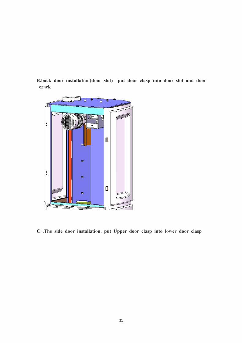
B.back door installation(door slot) put door clasp into door slot and doorcrack
C .The side door installation. put Upper door clasp into lower door clasp

22
2.7. tidy the wireTidy all the wires and fix them with band.
2.8. Top Pressure device installation
After install the door and cable inside of the machine ,and then install the top plate on themachine
Fix the plate on the top pressure device stand and the link the cable from the top plateto the stands.
Fix six screw ofthe plate on thestand of the toppressure device

23
After this step please link the cable from the top pressure device to the machine .
Fix top of the toppressure device on thetop of the machine
Fix the bottom of the top pressuredevice on the machine .

24
Put the yellowcover onto toppressure device
Put the yellowcover onto toppressure device

25
3 test equipment
3.1 matters needing attention
A.please confirm the use of the machine power supply, do not plug the wrong power,the machine uses a single phase AC220V, the dual color line for the ground, from theprotection
B.When the machine is running, it is strictly prohibited to put the foot on the machine.
C.not allowed to install the machine on the soft ground
D. not allow the object to be wrapped around the disc edge
E.emergency, can press the emergency stop switch, disconnect the motor powersupply, so that the machine emergency stop
F. after the completion of the work of the day, please clean the machine once
G. in order to ensure safety, please do not arbitrarily open electrical equipment
H. only electrical technician can repair electrical equipment

26
3.2 test preparation
A. to check the correctness of electrical connection, and to ensure that the groundsafety ground
B. to check whether the installation bolt is missing, and confirm its tightness
C. to confirm the equipment turnover no debris, tools and spare parts have beencompleted
D. confirm that the height of the photoelectric direction is not more than the edge ofthe minimum product
3.3 equipment pretest
watch out!:
To carry out any of the following operations, The other hand should be placed in the"emergency stop" button, to be able to press "emergency stop" in the first time, andfind the problem, when the problem has not been resolved do not follow the steps(problem solving methods, see "six, deliberately excluded)
A.connect the power supply and turn on the power switch, waiting for the system tostart
B. with a finger tap into the "manual screen" (see photo)

27
C. click on the "turntable" button to try to turn the turntable, confirm the "turntable"easy to start and no abnormal sound after the click again to stop
D. click on the "mold up" button will rise to the top of the device will be raisedautomatically stop, confirm the rise of smooth without blocking
watch out!:
A.when the device stops, please observe the lift in the column should havetouched the upper limit of the travel switch (see photo)

28
B. click on the "down" button to move the film seat down, move to 1M height, click"stop" to confirm the smooth without blocking
C.click the "electromagnet" button,Observation of blocking device is normal up (see photo)
watch out!:
No matter blocking device whether bounce, should click the "electromagnet"button in the 5S to turn it off (to avoid long time electricity burn)
After the automatic reset, the lifting body should have touched the end of the limit ofthe travel switch (see photo)

29
3 device parameters
name parametersupply voltage AC220V、50Hz、0.8KW (drag pull、1.2KW(pre pull)
turntable Speed 0-13r/minLifting body Limit or adjust film winding height standard
Film tensilecomponent
The tightness of the film can be adjusted automatically byfrequency conversion, and the tension of the film can be adjustedautomatically.

30
The film can be controlled by the adjustment of the handle.
film
The maximum thickness of the film is 0.035MMThe diameter of the shaft diameter phi 50-75MM thin filmThe maximum diameter of less than 250MM filmsFilm width is 500MM
Packing objectThe maximum packing weight is 1500KGThe maximum packing height is the total height of the columnis reduced by 400MM
enclosure Slope body
Machine size
Turntable diameter is phi 1500:2340*1500*H (2000 ~ 3000)can be customizedTurntable diameter is phi 1650:2540*1650*H (2000 ~ 3000)can be customizedTurntable diameter is phi 1800:2630*1800*H (2000 ~ 3000)can be customizedTurntable diameter is phi 2000:8440*2000*H (2000 ~ 3000)can be customized
Machine weight 650KGWorking noise Working noiseenvironmentcondition
The temperature is less than or equal to 98% temperature0-40
4 Equipment introduction
1. overview of devices and Applications
This machine is widely used in chemical fiber, tobacco, pharmaceutical, publishing,refrigeration, home appliances, ceramics, hardware, chemical industry, cans and otherindustries, high production efficiency to prevent the goods damaged in the process ofhandling, and dust, moisture-proof and cleaning effect. As the winding machine of therevolution, the device also has general winding machine has the followingadvantages:A. high efficiency, energy saving, stability, (a) automatic cutting film saving artificial180 seconds, Hengli membrane to avoid damage to the product, and save more than

31
30% of the consumables, automatic rope to avoid products falling from the pallet andfinish all this in silence, 3 years warranty, jsk is winding packaging revolution.(b) industry leading jsk intelligent LCD touch screen, the operation is extremelysimple, containing cover operating instructions, troubleshooting, at a glance, a button.
B. intelligent, convenient: equipped with intelligent remote control device DriveX,forklift workers do not need to get off, just gently a key, you can complete theautomatic packaging process, a remote control can be remotely controlled by anumber of machines.
C. no gas, no fault of the automatic cutting film: with jsk patent drive x automaticcutting film system is a revolution, without gas drive, only you can control the weak,decreasing the size of the requirements for the use of the environment. Only artificialgoods placed on pallets and the start button will automatically film winding in thegoods, without any waste. When the wound after packaging, it will automatically cutoff the film. On one side of the membrane will perfect adhesion goods, packaging,side machine on the membrane and is ready packaging a cargo tray, the whole processwithout artificial participation.
D. constant a membrane system: special constant a membrane system, the adverseeffects in at the corner of the products and plane membrane of tightness of the same,and wrapped the tightness can be through the touch screen control, fundamentallysolve the general winding machine winding products (especially the length and widthof the gap is larger) Shi Guai angle is tight planar Chi.
E. wrap rope system: at the bottom of the local rope enhances the degree of productsand the pallet with fastening, even when subjected to severe vibration, air cannot slidefrom the pallet. And it can solve the forklift pallet on the bottom of the spiral woundmembrane damage. Throughout the rope enhances the overall goods wrapped aroundthe strength of the packaging, reduce the transportation damage to the product. Thewhole and local rope will completely replace traditional horizontal packaged.F. ABS and metal unique combination: bearing metal frame, coupled with the ABSpanel, the perfect combination, not only reduces the overall weight of the machine,but also to make the panel has a collision buffer function, and beautiful and full oftexture.

32
2 . introduction of the whole machine

33
Serial no. Drawing no. Part name no.1 Alarm device 12 Alarm fixed screws 43 916B-0201-P023 Side door panel 34 916B-0201-P022 rear door panel 35 916B-0201-PA01 columns 16 916B-0201-P021 Front Door panel 37 columns install screw 28 columns install screw 29 916B-0201-SA01 film carriage 110 film carriage install screw 211 film carriage the chain tension screw 112 916B-0201-NA01 Chassis 113 916B-0201-CA01 Cutting system 114 916B-0201-C014 Cutting system Fixed block 215 Cutting system install screw 6
34
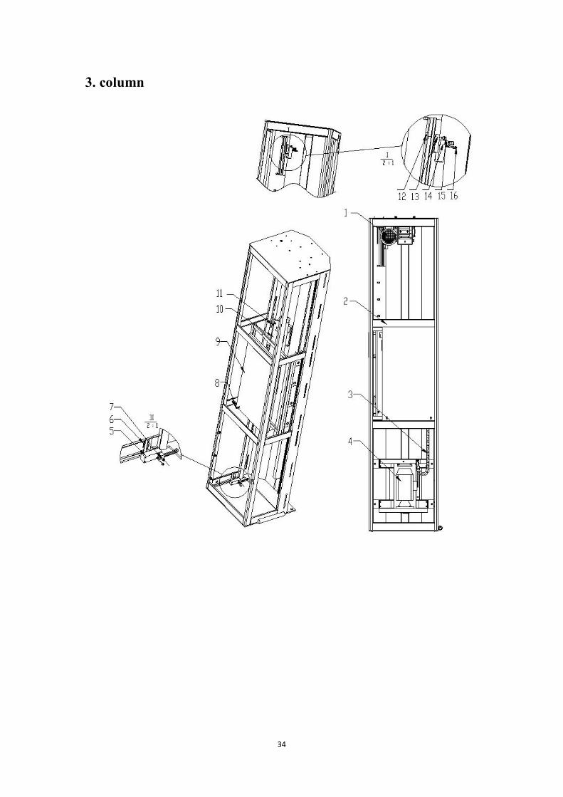
3. column
35
Serial no. Part name Drawing no. no.1 Up&down power unit 916B-0201-QA02 12 columns 916B-0201-PA01 13 Up&down Tank chain 14 Up&down install 916B-0201-QA04 15 Micro switch 16 Micro switch Fixed nut 916B-0201-N013 87 M4*30 screw/Spring gasket/Flat gasket 48 M5*12 screw/Spring gasket/Flat gasket 29 Distribution board 916B-0201-P006 110 Electrical shield plate 916B-0201-P007 111 M5*12 screw/Spring gasket/Flat gasket 916B-0201-Q011 412 Travel switch positioning nut 916B-0201-P019 113 Travel switch positioning board 916B-0201-P018 114 Micro switch 115 M6*12 screw/Spring gasket/Flat gasket 116 M4*30 screw/Spring gasket/Flat gasket 1
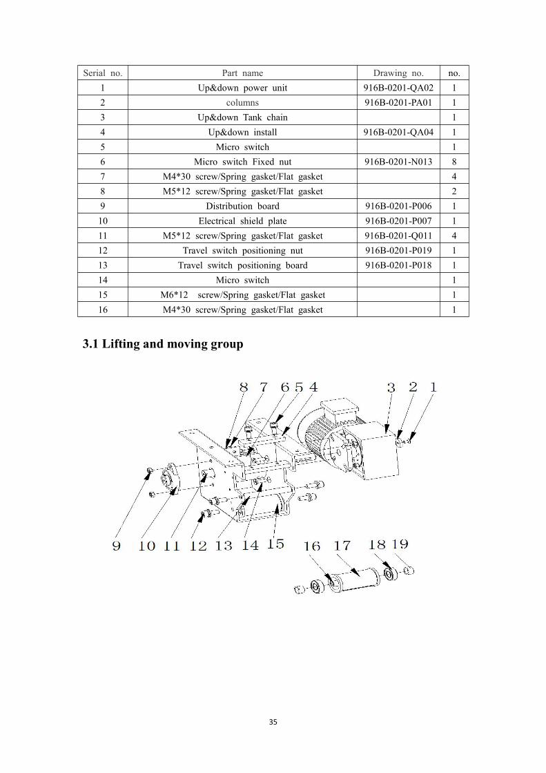
3.1 Lifting and moving group

36
Serial no. Part name Drawing no. no.1 M6*15 Flat head screw 12 Limit piece 916B-0201-Q014 13 Up&down motor 916B-0201-Q030 14 Bag keep plate 916B-0201-Q013 15 M8*25 screw/Spring gasket/Flat gasket 26 Receives the belt clamp cover 916B-0201-Q018 17 M6*15 flat screw 28 Top belt Guide shaft 916B-0201-Q012 19 M8 NUT 610 bearing block 916B-0201-Q032 111 Take-up shaft 916B-0201-Q019 112 M10*25 screw/Spring gasket/Flat gasket 413 Top belt Guide shaft 916B-0201-Q021 114 M8*25 Flat head screw 916B-0201-QA03 615 Receives the belt fixed pulley group 116 Top fixed axle 916B-0201-Q024 117 Top fixed body 916B-0201-Q020 118 Take-up with bearing 916B-0201-Q034 219 Top fixed axle sleeve 916B-0201-Q025 2

37
3.2 Lifting body

38
Serial no. Part name Drawing no. no.1 Leather belt activity end fixed plate 916B-0201-Q011 12 M4*12 screw/Spring gasket/Flat gasket 23 Up&down Hook the wheel 916B-0201-QA05 14 M8 screw/Spring gasket/Flat gasket 25 Up$down body 916B-0201-QA07 16 M6*12 screw/Spring gasket/Flat gasket 87 Guide wheel installment 916B-0201-QA06 48 M8 screw/Spring gasket/Flat gasket 49 M8*25 screw/Spring gasket/Flat gasket 410 Up&down motor 916B-0201-Q031 111 Guide wheel rack 916B-0201-Q011 412 Guide wheel 916B-0201-Q029 413 Guide wheel bearings 6000 814 Guide wheel axle sleeve 916B-0201-N028 815 M8*15 head screw 816 Up&down wheel axle 916B-0201-Q023 117 Up&down wheel body 916B-0201-Q022 118 Bearings for lifting hooks 916B-0201-Q035 219 Lifting wheel axle sleeve 916B-0201-Q026 2
4. chass

39
Serial no. Part name Drawing no. no.1 M10*25 head screw 62 turntable 916B-0201-N001 13 chain wheel 916B-0201-NA04 14 Rotation main axle clamp 916B-0201-N044 15 Rotation main shaft bearing 916B-0201-N046 16 Rotation main axle thrust bearing 916B-0201-N045 17 Chassis frame 916B-0201-NA02 18 M6*20 screw/Spring gasket/Flat gasket 29 Induction block 916B-0201-N024 110 Bracket 916B-0201-N029 111 sensors 916B-0201-N053 112 M5*15 screw 213 Spare chain tray 916B-0201-N042 114 The chain protects the lap 916B-0201-N059 115 M5*15 flat head screw 416 Gear motor 916B-0201-N055 117 M10*25 screw/Spring gasket/Flat gasket 418 M8*25 screw/Spring gasket/Flat gasket 419 Chain 12A 916B-0201-N056 120 Main Rotary sprocket 916B-0201-N040 121 Tightens the chain wheel inside caliper 916B-0201-N052 122 Tightens the chain wheel bearing 916B-0201-N051 123 Rotary sprocket 916B-0201-N041 124 Tightens the chain wheel outside caliper 916B-0201-N050 125 Bottom sprockets outside calipe 916B-0201-N048 126 Bottom sprockets 916B-0201-N038 227 Impeller Impeller 916B-0201-N039 128 Impeller bearing 916B-0201-N049 229 Impeller inside caliper 916B-0201-N047 2

40
5. Film carriage

41
Serial no. Part name Drawing no. no.1 Mold shield S022 12 Mold shield fixed column S023 13 Mold shield fixing plate SA04 14 Guide wheel S039 25 Pulls the membrane drum S048 26 Film frame transmission cover S014 17 Membrane holder with steel bushing(Door pivot point) S025 28 Open the door limit board S024 19 Transition wheel group SA15 210 Membrane holder with steel bushing( door limit board) S025 211 Transmission driven sprocket S051 112 pressing plate S047 313 M5*16 flat head screw 314 Safety plate S047 115 Safety plate torsional spring S062 216 Bearing-61904 417 Pulls the membrane drum fixed stand S046 418 Tightens the axle sleeve S050 119 The hole uses the circlip (D=30mm) 120 Bearing -6200 121 Transmission drive sprocket S044 122 Micro-switch D3M-01K2 223 tension shaft S049 124 tension sprocket S052 125 Safety board shaft sleeve S065 226 Safety board 2 S058 127 M4 nut 2428 Pulls the membrane drum fixed stand S046 129 Bearing-61904 230 Transition shaft roof section S045 131 mounting plate S050 132 M4*20 flat head screw 433 Producing membrane driven sprocket S042 134 Flat chain 235 Transition shaft main parts S043 136 driven sprocket S044 1
42
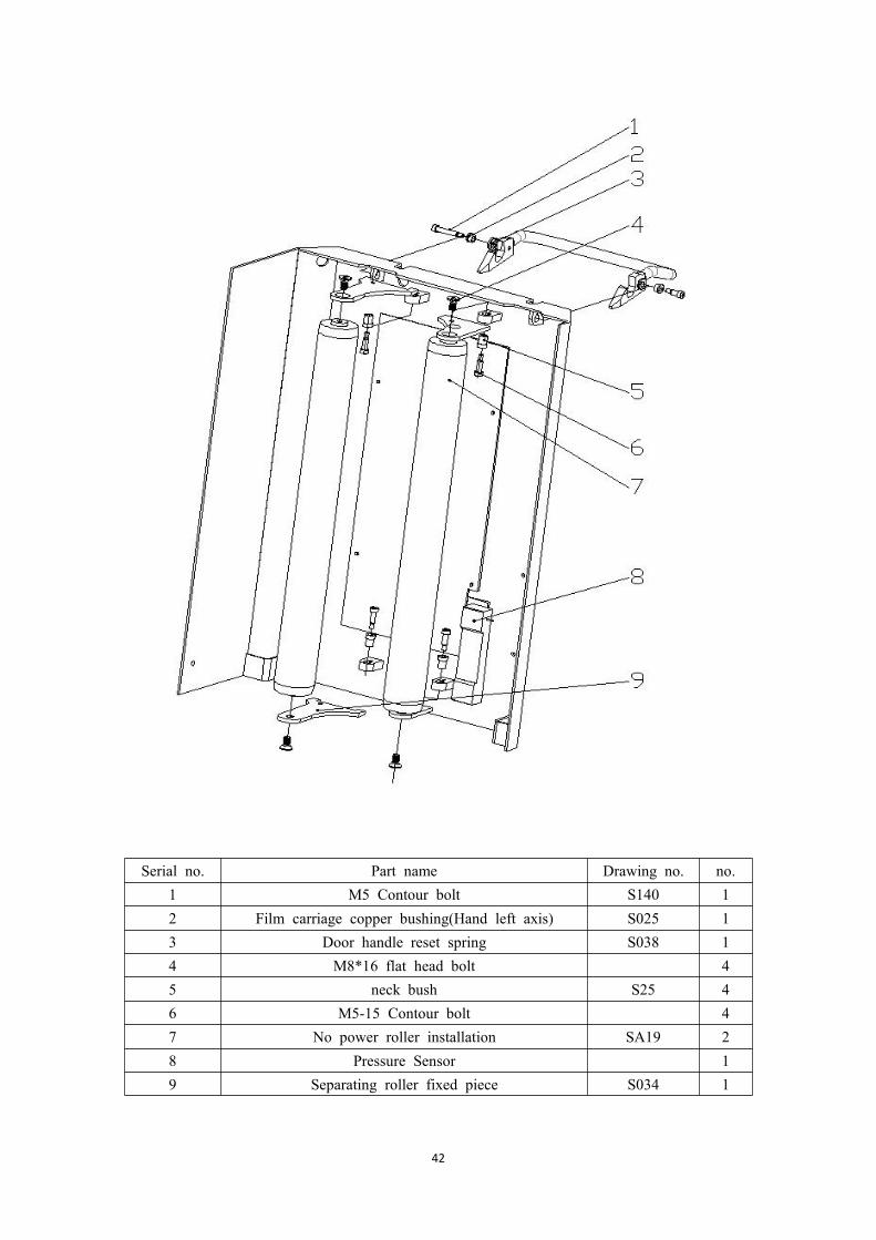
Serial no. Part name Drawing no. no.1 M5 Contour bolt S140 12 Film carriage copper bushing(Hand left axis) S025 13 Door handle reset spring S038 14 M8*16 flat head bolt 45 neck bush S25 46 M5-15 Contour bolt 47 No power roller installation SA19 28 Pressure Sensor 19 Separating roller fixed piece S034 1

43
Serial no. Part name Drawing no. no.1 System rope Skeleton plate 916B-0201-R001 12 System rope power pole 916B-0201-R002 13 System rope guidance copper bushing 916B-0201-R009 14 With actuator 916B-0201-R012 15 Rope wheel device 916B-0201-R007 16 The system rope guidance body seals the head plate 916B-0201-R004 17 Process-wide rope plate 916B-0201-R003 18 Foma wheel 916B-0201-R011 19 Rope guide shaft 916B-0201-R005 110 Rope lifting 916B-0201-RA02 1

44
6. Electromagnet obstruct device
Serial no. Part name Drawing no. no.1 Assembly welding parts 916B-0201-AA02 12 M6-12 Round head screw nut 13 Install the transition plate 916B-0201-A005 24 Electromagnet connection point 916B-0201-A011 15 Traveling schedule control bushing 916B-0201-A007 16 assembly board 916B-0201-A009 17 Traveling schedule control bushing 916B-0201-A007 18 Circlip 916B-0201-A013 29 torsional spring 916B-0201-A016 110 Electromagnet 916B-0201-A015 111 lifting arm 916B-0201-A024 112 needle bearing 916B-0201-A024 113 Stop arm 2 916B-0201-A023 114 needle bearing 916B-0201-A024 215 M4-10 screws 216 Cam-connecting block 916B-0201-A008 117 Inverted CAM roller 916B-0201-010 118 M5 Contour screw 119 Traveling schedule control bushing 916B-0201-A007 220 needle bearing 916B-0201-A024 221 Stop arm 2 916B-0201-A022 1

45
7.cutting film system
Serial no. Part name Drawing no. no.1 M8-35inner Hexagon socket head screws 12 M6-45 inner hexagon socket bolts 53 transformation leather belt D010 14 Belt sheeting D008 15 Cutting film device 16 spring strut 2 K004 27 M3-20 inner hexagon socket bolts 28 Belt Power frame DA02 19 Reset tension spring D011 110 CAM follower D009 111 M8-12 inner hexagon socket bolts 112 M8- spring washer 213 Belt Pulley bearing pad F002 214 Rotates the belt pulley E001 215 belt pulley bearing E007 216 Belt pulley installment axis F001 117 M8-20 inner hexagon socket bolts 118 Belt chute D001 119 Belt chute pulley D002/D003 120 The belt tension wheel fixed axis E004 121 Cutting film frame CA01 122 Belt pulley torsional spring E009 223 Belt fixed shaft E003 124 Cutting film frame 225 M5-5 inner hexagon socket bolts 126 Tension Transition mounting plate E002 1

46

47
Serial no. Part name Drawing no. no.1 Activity blade supporting structure G006 12 M6-12 round screw 43 Blade outer gasket G005 34 knife rest Protective Steel cover G004 15 M5 lock nut 56 Blade inner gasket G003 17 Cutter on fixed shaft G002 18 Activities knife revolution axis G016 19 Blade open torsion spring G020 110 Cutter adjusting shaft G014 111 Power board G015 112 Cutting knife reset torsion spring G021 113 CAM roller 414 Cutter rotation axle sleeve G019 115 drive shaft washer 1 J003 116 movable racks J001 117 Base plate J006 418 Pillar J005 119 M5-25 Bolt 120 Wire rails G008 121 Clamps the membrane movement arm J008 122 drive shaft washer 2 J004 223 Initiative circlip1 J007 224 shaft J002 125 Clamps the membrane driven axle sleeve G007 126 shaft K001 127 spring strut K004 128 knuckle bearing K005 229 knuckle bearing Connecting rod K006 130 Puts the membrane extension spring K007 131 rotating sleeve L002 232 The bottom fixed plate G010 133 active plate G011 134 spring L006 135 Upper fixing plate G009 136 Leads the film wheel M001 137 Leads the film wheel axle sleeve M002 138 Fixed contour bolt M003 139 Fixed blade frame J013 140 Fixed blade G013 141 M6-20 inner hexagon flat head screw 442 Activities blade G012 1

48
5 Human computer interface
1.Starting page
Finger click on the screen to enter the automatic operation of the screen

49
2. automatic page
Help: click switch to help screen.Turntable speed: used to set the chassis in the normal operation of the speed ratio,100% - 0 corresponds to the frequency of 0 - 50Hz (the greater the percentage, thefaster the speed).Up down speed: used to set the speed ratio of the membrane seat lift, 100% - 0corresponding to the frequency of 0 - 50Hz (the greater the percentage, the faster thelifting speed).Pre-stetch rate : used to set the normal operation of the film seat put the proportionof elastic membrane (the larger the percentage, the film speed quick release, Mo Songis too tight easy directly pull off and not live clip, too loose may leads to incompletefilm broken; general settings in 18%-40%, please according to the fine-tuning of theshape and size of the film toughness and pallet objects.

50
Pressure :the top pressure up and down speedLength: the measure of the how many meter film have been used on palletOutput cleared: click can be cleared of a single output.Memoria: .6 wrapping model for different pallet ,need input data according to yourselfFeather selection: single model ,choose film just go up and then stop ,or chosereturn ,film up and down and stopStart: in the absence of any manual action, click to start winding machineautomatically run.Pause: click can make the current action in a paused state, once again, click continueto run, in both the automatic and manual can be used.Reset: click the winding machine to immediately stop the current action, and then liftand chassis were reset to the initial position.Alarm clear : click to cancel alarm

51
3. manual page
Help: click switch to help screen.Turntable speed: used to set the chassis in the normal operation of the speed ratio,100% - 0 corresponds to the frequency of 0 - 50Hz (the greater the percentage, thefaster the speed).

52
Up down speed: used to set the speed ratio of the membrane seat lift, 100% - 0corresponding to the frequency of 0 - 50Hz (the greater the percentage, the faster thelifting speed).Pre-stetch rate : used to set the normal operation of the film seat put the proportionof elastic membrane (the larger the percentage, the film speed quick release, Mo Songis too tight easy directly pull off and not live clip, too loose may leads to incompletefilm broken; general settings in 18%-40%, please according to the fine-tuning of theshape and size of the film toughness and pallet objects.
Turntable: when you are not in a state of automatic operation, click the turntable torotate, and once again, the turntable stops.Mold up: in the state of the automatic operation, click the film rise, again click thefilm seat to stop rising, when the film seat to reach the upper limit of the film seat alsostopped rising.Mold down: in the state of the automatic running, click the film seat down, againclick the film to stop the decline, when the film seat to reach the lower limit of thefilm seat also stopped falling.Pressure Up :top pressure device go upPressure Down:top pressure device go downElectromagnet: not in state of automatic operation, click the electromagnet pop-upagain click electromagnet stop electricity electromagnet need external force will beretracted.Alarm clear : click to cancel alarm

53
4. parameter settings page
Help: click switch to help screen.Turntable speed: used to set the chassis in the normal operation of the speed ratio,100% - 0 corresponds to the frequency of 0 - 50Hz (the greater the percentage, thefaster the speed).

54
Up down speed: used to set the speed ratio of the membrane seat lift, 100% - 0corresponding to the frequency of 0 - 50Hz (the greater the percentage, the faster thelifting speed).Pre-stetch rate : used to set the normal operation of the film seat put the proportionof elastic membrane (the larger the percentage, the film speed quick release, Mo Songis too tight easy directly pull off and not live clip, too loose may leads to incompletefilm broken; general settings in 18%-40%, please according to the fine-tuning of theshape and size of the film toughness and pallet objects.Top Circle: used to set the top to strengthen the number of rings, the film will rise tothe height of the product after the stop, until the completion of the top to strengthenthe number of laps before fallingBottom circle : used to set the number of rings to enhance the bottom, the film willstay at the bottom until the completion of the bottom to strengthen the number of lapsand then carry out other actions.Up and down times: used to set the film seat lifting round-trip times, set for a roundtrip, set to 2 to travel between the two, and so on.Over top time: used to set the time when the film rises to the height of the product(photoelectric sensor less than the product) continues to rise.System parameters: click the system parameters of the device.The next page: click switch to the next screen.Chinese: Click to switch the language to Chinese.English: Click to switch the language to English.
4.1system parameter page

55
Slow start time: for setting the chassis from the static to start to the normal operationof the speed of the time (the shorter the time set, the disc starts to pull the film larger).Pre-stretch rate reset :used to set the chassis to enter the broken film to stop thespeed (speed control, directly related to the initial position of the turntable accuracy;generally set between 20%~25%, set up after the customers do not easily change)Before slow delay time: it;s at the end of circle ,the slow speed setting

56
4.2 I/O monitor page
Automatic screen: click switch to automatically operate the picture.Manual screen: Click to switch to manual operation.Set the screen: display the current picture as the parameter settings screen.Alarm screen: click switch to the alarm view screen.Help: click switch to help screen.PLC terminal monitoring: display the real-time motion of the PLC on the situation.

57
On a page: click switch to the top of a picture.
5 .help page
Displays help information for the device.Returns: Click to return to the previous screen.ID: display the device number for this device.

58
6 Operating procedures
1.starting up
Turn the power switch to ON and click on the start screen to enter the operationscreen.
2.Mounting film
2.1 install membrane preparation
A. Take up wrapping film rolls, and identified as the machine pre-stretch PEmembraneB. to confirm the direction of the placement of the film according to picture below(in the direction of downward observation)
C. confirm that the film carriage is in the initial position, (and had better to turn offthe power when the time allowed.)

59
2.2 install film
A. pull the membrane door handle with the hand to open the membrane doorB. the film roll head pulled about 50-60cm length, and then set to the correct directionof the film roll (see photo)
C. the film coil head is elongated and wrapped around the film seat 3/4 volume in thedirection of the icon and the direction of the turntableD. closes the membrane door bodyE. film head is fixedly connected with the bottom of the product pallet

60
watch out!:
1.Close the door shut the door body wrap at relaxation can reduce shut2.In the process, we should avoid the human body contact with the membrane seat ofthe moving parts3.After the door body is closed, it is best to use the hand to press down the handle toconfirm that the door is closed.
7 Common breakdown and elimination
1. indicator light doesn’t work
1.1 power not open: open power1.2 power not inserted: plug in1.3 indicating lamp is bad: change indicator light
2.turntable doesn’t work
2.1 power is not connected or missing: check power supply2.2 chain break or fall off: to re-install the chain and confirm the tension chain, thetension after the confirmation of tension screw fixation, no loosening.2.3 frequency converter regulating knob to adjust the minimum position: adjust to areasonable position (non - technical personnel to prohibit the random adjustment ofequipment parameters and equipment on some variables set)2.4 emergency stop switch in the stop position: open the emergency stop switch.2.5 whether control button is invalid: confirm, if the connection is loose because ofthe connection line to re fixed. If the button itself is damaged, the need to replace thebutton.
3.lifting device doesn’t work
3.1 emergency stop switch in the stop bit: open the emergency stop switch3.2 frequency converter regulating knob to adjust the minimum position: adjust to areasonable position (non - technical personnel to prohibit the random adjustment ofequipment parameters and equipment on some variables set)3.3 power is not connected or missing: check power supply3.4 limit switch or turntable count sensor failure to confirm whether the switch or

61
sensor is loose, if the position is correct, if the position is correct and no loose.confirm the switch or sensor is damaged, if there is damage to the replacement.3.5 chain rupture or stuck: to confirm whether there is a foreign body involved in thechain, the chain tension to relax, to re install the chain, adjust the tension.
4.stretch film is pulled off
4.1 winding film has a fracture or poor quality: replacement of the winding film.4.2 Pre-stretch chain off or sprocket loose; re-install the chain or tighten the sprocket.4.3 pre-tension motor speed and motor speed, no turntable: adjusting the speed ofboth good, which match.
5.Electromagnet obstruct device doesn’t work
5.1 obstruct can’t normal bounce; confirm that whether the obstruct quick andconnection quick plug is loose, Not plugged in.5.2 obstruct can’t normal bounce; Human Machine Interface, click the electromagnetmagnet, confirm that whether electromagnet can work normally, if not,then replacethe electromagnet.
6.cutting film system doesn’t work6.1 film can not be cut offThe rope height is too high, adjust the rope height to the appropriate position.confirm that whether the compression spring screw is loose, if there is loose, tightenthen.6.2 film can’t be gripedChassis speed is too fast, adjust slowly the speed6.3 film is pulled off:Confirm the quality of the same batch of film, replace the winding film.
8 Equipment safety precautions
1. confirm the power of the machine, the machine uses a single-phase AC220V. dualcolor line for the ground wire.2. when the machine is running, it is strictly prohibited to pedal on the machine.3. the installation of the machine can not be installed on the soft ground.4.prohibit the need to wrap objects placed on the edge of the turntable.5.in case of emergency, press the emergency stop switch and power off the machine.6. after the completion of the work, should clean the machine once.7.non professional personnel, can not be arbitrarily open electrical equipment.

62
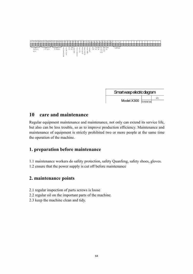
9 Circuit diagram

63
64
10 care and maintenanceRegular equipment maintenance and maintenance, not only can extend its service life,but also can be less trouble, so as to improve production efficiency. Maintenance andmaintenance of equipment is strictly prohibited two or more people at the same timethe operation of the machine.
1. preparation before maintenance
1.1 maintenance workers do safety protection, safety Quanfeng, safety shoes, gloves.1.2 ensure that the power supply is cut off before maintenance
2. maintenance points
2.1 regular inspection of parts screws is loose2.2 regular oil on the important parts of the machine.2.3 keep the machine clean and tidy.

65
3.key maintenance instructions
3.1 open between the turntable and the upright post cover, chassis chain apply to theamount of lubricating oil, in the man-machine interface manually according to therotation of the turntable, to the whole chain of oil. (recommended every three monthson an oil)
Open the cover to the chain chain oil

66
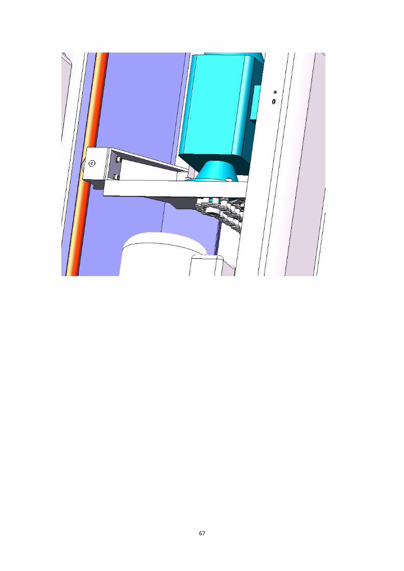
3.2 the lifting body rises, to open the side door mold base chain oil (recommendedevery three months on a)
67

68
9.safety device
1.Feet &head protect system
Picture 3.1.5-1
Foot and head protect system is main for protect the operator safety ,if the film
carriage go up over the operator head , if the operator in under the film carriage
during the carriage do down ,if the film carriage touch the head of the operator ,the
machine will stop work immediately and LED light will alarm at same time so
that avoid the film carriage hurt the operator head , the film go down to
to floor ,if the operator feet in under the potion of the film carriage ,when the film
carriage touch the foot of the operator ,the film carriage will stop go down
immediately and the LED light will alarm .in this way ,the film carriage will not hurt
the operator ‘s foot. See picture 3.1.5-1
2.Open door safety system
Foot&headprotectdevice

69
3.1.5-2
Open door safety system is main for the safety of operator when replace new film or
open door to fix machine ,after the operator open the door ,the machine will stop
work ,and the machine can not start any more ,just when the operator close the door
again and then can let the machine run again. See picture
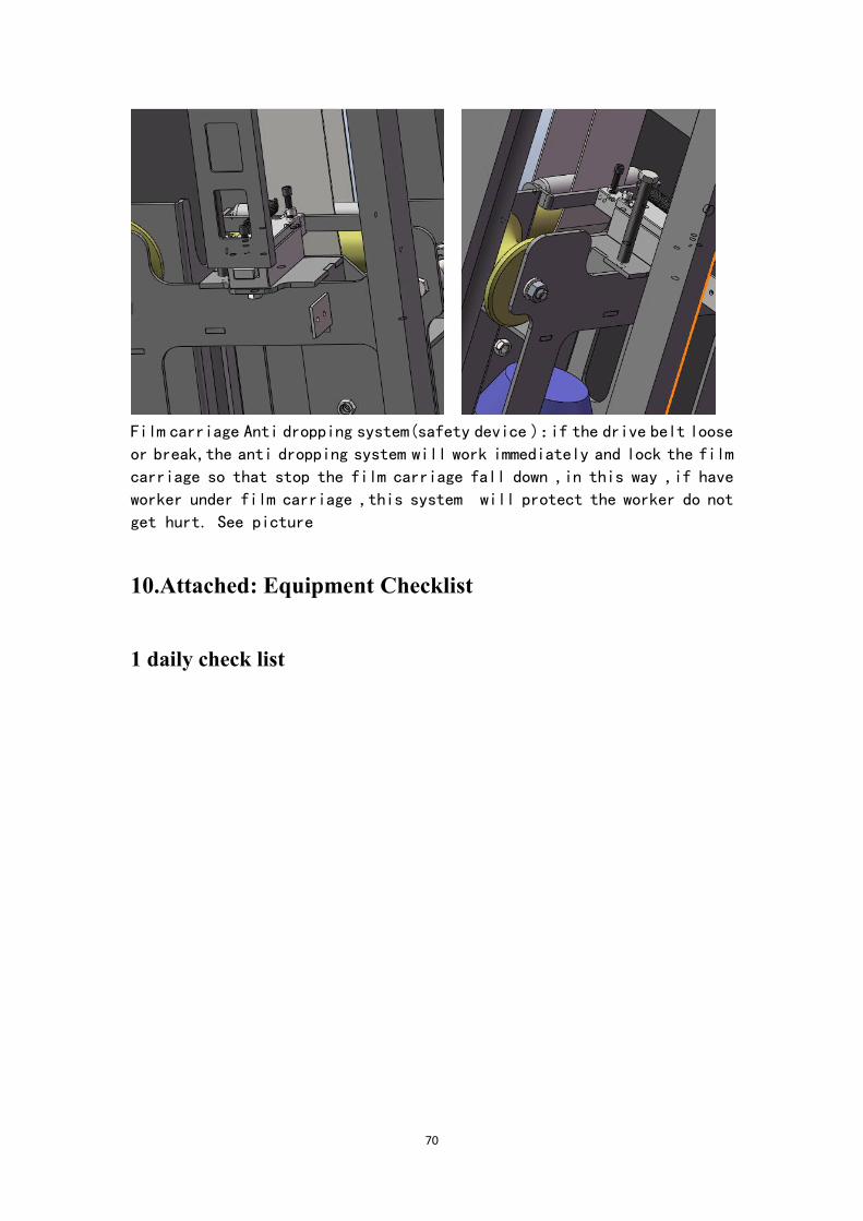
3. Film carriage Anti dropping system
Open Doorsafety system
70
Film carriage Anti dropping system(safety device ):if the drive belt looseor break,the anti dropping system will work immediately and lock the filmcarriage so that stop the film carriage fall down ,in this way ,if haveworker under film carriage ,this system will protect the worker do notget hurt. See picture
10.Attached: Equipment Checklist
1 daily check list

71