Embed Size (px)
Citation preview

SMARTQuake® v3.8 User’s Guide
1
SMARTQuake® v3.8
SMART Series Automated EarthQuake Data Processor
User’s Guide
Copyright 2003-2011 Geotech Instruments, LLC Dallas, Texas

SMARTQuake® v3.8 User’s Guide
2
Document History
Date ECN Rev Initials Description
12/10/01 1.0 Initial Release
05/22/03 2.0 Updated Document
07/08/03 2.1 Updated Document
12/17/03 2.2 Updated Document
03/05/04 2.3 Updated Document
03/26/04 2.4 Updated Document
03/11/05 2.6 Updated Document
03/29/05 2.7 Updated Document
06/03/05 3.0 Updated Document
07/20/05 3.0 Updated Document (version unchanged)
09/02/05 3.0 Updated Document (version unchanged)
02/28/06 3.1 SMARTExtract Updates
05/01/06 3.2 SMARTShake Updates
05/20/07 3.3 Updated Document
11/14/08 3.6 SmartRing Updates
8/21/09 3.7 SmartProc Updates
4/3/11 3.8 Installation Updates

SMARTQuake® v3.8 User’s Guide
3
Contents
1 SMARTQUAKE® OVERVIEW........................................................................................................... 9 1.1 INTRODUCTION.............................................................................................................................. 9 1.2 SYSTEM REQUIREMENTS ............................................................................................................. 12 1.3 EVENT DETECTION SCHEME........................................................................................................ 12 1.4 PROCESSING STAGE..................................................................................................................... 15 1.5 OTHER FEATURES........................................................................................................................ 17
2 SMARTQUAKE® INSTALLATION................................................................................................. 19
3 SMARTQUAKE® CONFIGURATION............................................................................................. 23 3.1 SMARTQUAKE® DIRECTORIES AND FILES ................................................................................ 23 3.2 SETTING UP SMARTQUAKE® .................................................................................................... 25
3.2.1 General Settings ................................................................................................................. 28 3.2.2 Station Settings ................................................................................................................... 34 3.2.3 Detection and Event Settings.............................................................................................. 39 3.2.4 Event Location Settings ...................................................................................................... 41 3.2.5 P-Wave Velocity Model ...................................................................................................... 44 3.2.6 Seismic Source Inversion Settings ...................................................................................... 45 3.2.7 Networking Settings............................................................................................................ 48 3.2.8 Messaging Settings ............................................................................................................. 51 3.2.9 Regenerate Parameter Files ............................................................................................... 57
4 SMARTQUAKE® OPERATION ....................................................................................................... 58 4.1 COMMANDS................................................................................................................................. 59 4.2 OPERATION ................................................................................................................................. 61 4.3 SETTINGS..................................................................................................................................... 63 4.4 RUNNING SMARTQUAKE®........................................................................................................ 64
5 SMARTQUAKE® DATA EXTRACTION TOOL ........................................................................... 65 5.1 INSTALLING SMARTEXTRACT ................................................................................................... 65 5.2 CONFIGURING SMARTEXTRACT ................................................................................................ 65 5.3 RUNNING SMARTEXTRACT ....................................................................................................... 68
6 REFERENCES ..................................................................................................................................... 71
7 APPENDIX 1 – SMARTQUAKE® LOCAL EVENT OUTPUT ..................................................... 73 7.1 LOCATION AND SOURCE PARAMETERS FOR A LOCAL EARTHQUAKE............................................. 73
8 APPENDIX 2 – SMARTQUAKE® DISTANT EVENT OUTPUT.................................................. 79 8.1 LOCATION PARAMETERS FOR A DISTANT EARTHQUAKE............................................................... 79
9 APPENDIX 3 – SMARTQUAKE® INTERFACE TO LIVE INTERNET SEISMIC SERVER - LISS (IF THIS OPTION IS PRESENT)............................................................................................. 85 9.1 INSTALLATION............................................................................................................................. 85 9.2 CONFIGURATION ......................................................................................................................... 85 9.3 RUNNING SUDS2LISS................................................................................................................ 86

SMARTQuake® v3.8 User’s Guide
4
10 APPENDIX 4 – INSTALLATION OF THIRD-PARTY SOFTWARE OPTIONALLY USED BY SMARTQUAKE®AND SMARTSHAKE.................................................................................... 87 10.1 THE GENERIC MAPPING TOOLS (GMT)....................................................................................... 87
10.1.1 GMT Installation ................................................................................................................ 87 10.1.2 GMT Customization............................................................................................................ 87
10.2 NETCDF ..................................................................................................................................... 87 10.3 GNU AWK................................................................................................................................... 88 10.4 GHOSTSCRIPT .............................................................................................................................. 88 10.5 SYSTEM ENVIRONMENT VARIABLES ............................................................................................ 88 10.6 GSVIEW....................................................................................................................................... 88
10.6.1 GSview Installation ............................................................................................................ 88 10.6.2 GSview Customization........................................................................................................ 88
10.7 IMAGEMAGICK............................................................................................................................ 89 10.8 ENSCRIPT .................................................................................................................................... 89
11 APPENDIX 5 – SMARTQUAKE® INTERFACE TO THE ICP SYSTEM WITH SEISAN FILES RECORDING (IF THIS OPTION IS PRESENT) ................................................................ 91 11.1 INSTALLATION............................................................................................................................. 91 11.2 CONFIGURATION ......................................................................................................................... 92 11.3 RUNNING SEI2QUAKE ................................................................................................................. 92
12 APPENDIX 6 – SMARTSHAKE STRONG MOTION PROCESSOR (IF THIS OPTION IS PRESENT)............................................................................................................................................. 95 12.1 SMARTSHAKE OVERVIEW ......................................................................................................... 95 12.2 SMARTSHAKE INSTALLATION ................................................................................................... 96 12.3 SMARTSHAKE FILES AND DIRECTORIES .................................................................................... 98 12.4 SETTING UP SMARTSHAKE ...................................................................................................... 100
12.4.1 General Settings ............................................................................................................... 102 12.4.2 Station Settings ................................................................................................................. 107 12.4.3 Detection and Event Settings............................................................................................ 110 12.4.4 Networking Settings.......................................................................................................... 112 12.4.5 Messaging Settings ........................................................................................................... 114
12.5 SMARTSHAKE OPERATION...................................................................................................... 115 12.5.1 Commands ........................................................................................................................ 116 12.5.2 Settings ............................................................................................................................. 118 12.5.3 Running SMARTShake...................................................................................................... 119
13 APPENDIX 7 – SMARTRING DATA RING BUFFER AND CONVERSION TOOL (IF THIS OPTION IS PRESENT)........................................................................................................... 121 13.1 SMARTRING OVERVIEW.......................................................................................................... 121 13.2 SMARTRING INSTALLATION.................................................................................................... 121 13.3 SMARTRING FILES AND DIRECTORIES..................................................................................... 123 13.4 SETTING UP SMARTRING......................................................................................................... 124 13.5 SMARTRING OPERATION......................................................................................................... 131
13.5.1 Commands ........................................................................................................................ 131 13.5.2 Settings ............................................................................................................................. 133 13.5.3 Running SMARTRing........................................................................................................ 134
14 APPENDIX 7 – SMARTPROC STRONG MOTION DATA PROCESSOR (IF THIS OPTION IS PRESENT) ..................................................................................................................... 135 14.1 SMARTPROC OVERVIEW ......................................................................................................... 135 14.2 SMARTPROC INSTALLATION ................................................................................................... 135 14.3 SMARTPROC FILES AND DIRECTORIES .................................................................................... 137 14.4 SETTING UP SMARTPROC ........................................................................................................ 141

SMARTQuake® v3.8 User’s Guide
5
14.4.1 General Settings ............................................................................................................... 143 14.4.2 Station Settings ................................................................................................................. 148 14.4.3 Detection and Event Settings............................................................................................ 151 14.4.4 Messaging Settings ........................................................................................................... 153
14.5 SMARTPROC OPERATION ........................................................................................................ 154 14.5.1 Commands ........................................................................................................................ 155 14.5.2 Settings ............................................................................................................................. 156 14.5.3 Running SMARTProc ....................................................................................................... 158
SMARTQuake® v3.8 User’s Guide
6
(Page Intentionally Left Blank)

SMARTQuake® v3.8 User’s Guide
7
Table of Figures Figure 1. Screenshot of SMARTQuake® processing a distant earthquake................................................ 10 Figure 2. Two examples of SMARTQuake® processing local earthquakes............................................... 11 Figure 3. Detection scheme for any active seismic channel; the black bars denote the end-of-files, the gray
bars symbolize the overlapping data (see text) .................................................................................. 13 Figure 4. Flow chart of the processing stage............................................................................................. 18 Figure 5. SMARTQuake® installation windows ........................................................................................ 20 Figure 6. SMARTQuake® initial window .................................................................................................. 21 Figure 7. SMARTQuake® Activation Dialog............................................................................................. 22 Figure 8. SMARTQuake® Successful Activation Window ......................................................................... 22 Figure 9. SMARTQuake® files configuration selection window ............................................................... 25 Figure 10. SMARTQuake® setting selection ............................................................................................. 26 Figure 11. SMARTQuake® save settings window...................................................................................... 26 Figure 12. SMARTQuake® end of configuration window ......................................................................... 27 Figure 13. SMARTQuake® General Settings window ............................................................................... 28 Figure 14. SMARTQuake® Station list window......................................................................................... 34 Figure 15. SMARTQuake® Station Settings window ................................................................................. 35 Figure 16. SMARTQuake® Detection and Event Settings window............................................................ 39 Figure 17. SMARTQuake® Event Location Settings window .................................................................... 41 Figure 18. SMARTQuake® P-wave Velocity Model window..................................................................... 44 Figure 19. SMARTQuake® Seismic Source Inversion Settings window .................................................... 45 Figure 20. SMARTQuake® Network Settings window............................................................................... 48 Figure 21. SMARTQuake® Messaging Settings window ........................................................................... 51 Figure 22. SMARTQuake® Email Messaging Settings window for location results in SMART format .... 52 Figure 23. SMARTQuake® Email Messaging Settings window for location results in IMS format and
Example of email message in IMS format .......................................................................................... 53 Figure 24. SMARTQuake® Email Messaging Settings window for location results of local events with
magnitudes M≥3 ................................................................................................................................. 54 Figure 25. SMARTQuake® Email Messaging Settings window for location results of events with
magnitudes M≥3.5 .............................................................................................................................. 55 Figure 26. SMARTQuake® Email Messaging Settings window for alert messages in Swiss Seismological
Service format, and an example of alert message .............................................................................. 55 Figure 27. SMARTQuake® Phone Messaging Settings window for SMS text messages, and an example of
SMS text message ............................................................................................................................... 56 Figure 28. SMARTQuake® end of configuration window ......................................................................... 57 Figure 29. SMARTQuake® Messages window .......................................................................................... 58 Figure 30. SMARTQuake® Command menu ............................................................................................. 59 Figure 31. Window with the Local Events Epicenter Map......................................................................... 62 Figure 32. Plot Local Events Dialog.......................................................................................................... 62 Figure 33. SMARTQuake® Settings menu ................................................................................................. 63 Figure 34. Configuration dialog of SMARTExtract ................................................................................... 66 Figure 35. SMARTExtract GUI.................................................................................................................. 68 Figure 36. Data Request dialog of SMARTExtract .................................................................................... 69 Figure 37. The output of SMARTExtract following processing of a data request ..................................... 70 Figure 38. Page 1 for a local event: the location information and source parameters results ................. 74 Figure 39. Page 1 for a local event, when the location is not possible: only the phase information is output
............................................................................................................................................................ 75 Figure 40. Page 2 for a local event: the real-time epicentral map, showing the location parameters and the
fault plane solution in the legend and insert, respectively ................................................................. 76 Figure 41. Page 3 for a local event: waveforms of the picked data channels............................................ 77 Figure 42. Page 4 for a local event: waveforms of all data channels........................................................ 78 Figure 43. Page 1 for a distant event: the location information ................................................................ 80 Figure 44. Page 1 for a distant event, when the location is not possible: only the phase information is
output.................................................................................................................................................. 81

SMARTQuake® v3.8 User’s Guide
8
Figure 45. Page 2 for a distant event: the real-time epicentral map, showing the location parameters in the legend ................................................................................................................................................. 82
Figure 46. Page 3 for a distant event: waveforms of the picked data channels......................................... 83 Figure 47. Page 4 for a distant event: waveforms of all data channels..................................................... 84 Figure 48. Example of the suds2liss.conf configuration file ...................................................................... 85 Figure 49. Example of the sei2quake.inp configuration file ...................................................................... 92 Figure 50. Example of Shake Map output by SMARTShake Strong Motion Processor ............................. 96 Figure 51. SMARTShake installation window............................................................................................ 97 Figure 52. SMARTShake directories window ............................................................................................ 97 Figure 53. SMARTShake files install window ............................................................................................ 98 Figure 54. SMARTShake end of installation window................................................................................. 98 Figure 55. SMARTShake configuration selection window ....................................................................... 100 Figure 56. SMARTShake settings selection .............................................................................................. 101 Figure 57. SMARTShake save settings window ....................................................................................... 101 Figure 58. SMARTShake General Settings window ................................................................................. 102 Figure 59. SMARTShake Station List window ......................................................................................... 107 Figure 60. SMARTShake Station Settings window................................................................................... 108 Figure 61. SMARTShake Detection and Event Settings window.............................................................. 111 Figure 62. SMARTShake Networking Settings window............................................................................ 113 Figure 63. SMARTShake Messaging Settings window............................................................................. 114 Figure 64. Example of SMARTShake email message............................................................................... 115 Figure 65. Example of SMARTShake SMS text message.......................................................................... 115 Figure 66. SMARTShake Messages window ............................................................................................ 116 Figure 67. SMARTShake Settings menu ................................................................................................... 118 Figure 68. Example of SMARTShake processing..................................................................................... 119 Figure 69. SMARTRing installation window............................................................................................ 122 Figure 70. SMARTRing directories window ............................................................................................ 122 Figure 71. SMARTRing files install window ............................................................................................ 123 Figure 72. SMARTRing end of installation window................................................................................. 123 Figure 73. SMARTRing configuration selection window ......................................................................... 124 Figure 74. SMARTRing General Settings window ................................................................................... 125 Figure 75. SMARTRing save settings window ......................................................................................... 130 Figure 76. SMARTRing configured window ............................................................................................ 130 Figure 77. SMARTRing Messages window .............................................................................................. 131 Figure 78. SMARTRing Settings menu ..................................................................................................... 133 Figure 79. SMARTProc installation window ........................................................................................... 136 Figure 80. SMARTProc directories window ............................................................................................ 136 Figure 81. SMARTProc files install window ............................................................................................ 137 Figure 82. SMARTProc end of installation window ................................................................................ 137 Figure 83. SMARTProc configuration selection window......................................................................... 142 Figure 84. SMARTProc settings selection................................................................................................ 142 Figure 85. SMARTProc save settings window ......................................................................................... 143 Figure 86. SMARTProc General Settings window ................................................................................... 144 Figure 87. SMARTProc Station List window ........................................................................................... 148 Figure 88. SMARTProc Station Settings window..................................................................................... 149 Figure 89. SMARTProc Detection and Event Settings window ............................................................... 152 Figure 90. SMARTProc Messaging Settings window............................................................................... 153 Figure 91. Example of SMARTProc email message ................................................................................ 154 Figure 92. Example of SMARTProc SMS text message ........................................................................... 154 Figure 93. SMARTProc Messages window .............................................................................................. 155 Figure 94. SMARTProc Settings menu..................................................................................................... 157 Figure 95. SMARTProc event detection ................................................................................................... 158 Figure 96. SMARTProc event waveforms plot ......................................................................................... 159

SMARTQuake® v3.8 User’s Guide
9
1 SMARTQuake® Overview
1.1 Introduction SMARTQuake® is a program package designed to perform high quality fully automated earthquake data processing and quasi real-time exchange of earthquake information. The core of SMARTQuake® is based on the SAPS seismological data acquisition and processing system (Oncescu et al., 1996) with a proven successful, reliable operation over more that eight years at several data centers in Europe. SMARTQuake® is a modular, easily extendable, fully specialized system, designed to run (even completely in background) in a Windows environment. It is available as a stand-alone product or integrated with Geotech’s SMARTGeoHub® Data Server.
SMARTQuake® starts by picking arrival times on selected pre-filtered channels. The waveforms after the picks are analyzed to discriminate between local and regional earthquakes, and teleseisms. S waves are also picked in case of local events. An iterative Geiger method is used for the location of local/regional earthquakes, and the plane wave method for the location of teleseisms. Wood-Anderson or duration magnitude is computed for local earthquakes and the body wave magnitude mb for teleseisms. Location results, waveforms with picks, and color epicentral maps are output on a PostScript printer. Event files are archived and converted to common seismological data formats like GSE or SAC. The location results are sent by email and/or SMS to a list of addresses/numbers immediately after the earthquake detection. The emails are already formatted as required by some of the most important seismological centers (IDC, NEIC, EMSC, Swiss Seismological Service, etc).
An optional module of SMARTQuake® performs moment tensor inversion for local earthquakes based on spectral amplitudes of body wave trains. Inversion applies constraints for zero trace or double couple source model. The output includes the moment tensor components, its principal P, T and B axes, the strike, dip and slip of the two nodal planes, the scalar seismic moment, together with a stereographic projection on the lower focal hemisphere. Moment-magnitude, stress-drop, source dimension, and energy released, all with standard errors, are also calculated automatically and appended to the outgoing emails.
Examples of SMARTQuake® output at processing local and distant earthquakes are shown in Figure 2 and Figure 1, respectively.
SMARTQuake® can be scheduled to send periodically state-of-health messages to the operator, and even to notify in case of network breakdowns. Other features include an optional circular buffer, a web interface, as well as interfaces to data exchange mechanisms as AutoDRM (Kradolfer, 1993) and USGS Live Internet Seismic Server (LISS). SMARTQuake® was tested on Windows 2000/XP computers, and in case of large networks, being computationally intensive, it is recommended to be run on a dedicated networked computer.
SMARTQuake® is also a stand alone application and seismic data can be input from any continuous file data acquisition system, on-line or off-line (such as the field disks from

SMARTQuake® v3.8 User’s Guide
10
large numbers of temporary deployed field data recorders). Data from different networks (or sub-networks) can be merged together into a single data stream for undergoing event processing. SMARTQuake® processes the input velocity recordings only, sending the acceleration data channels, if present in the raw data, to another specialized task, the SMARTShake real-time strong motion processor.
SMARTQuake® stores the raw data to a circular data buffer. It can also convert the raw data into another data format of choice (available options are CSS 3.0, MiniSEED, SAC or SEG-Y) for further processing by another specialized task (other than SMARTQuake®), or for backup. A simplified version of SMARTQuake® software that has only the functionality of maintaining the raw data circular buffer, and converting it to other formats, is called SMARTRing, and is available separately (see §13 - Appendix 7).
Paragraphs related to the SMARTQuake® features available only when functioning together with Geotech’s SMARTGeoHub® Data Server are marked by a frame.
Figure 1. Screenshot of SMARTQuake® processing a distant earthquake

SMARTQuake® v3.8 User’s Guide
11
Figure 2. Two examples of SMARTQuake® processing local earthquakes

SMARTQuake® v3.8 User’s Guide
12
1.2 System Requirements The minimal hardware requirements are: a Pentium II @ 266 MHz machine with 128 MB RAM, standard configuration, using Microsoft Windows 2000 Professional operating system. However, a Pentium III or higher machine is recommended for handling many channels and high sampling rates. SMARTQuake® was tested handling 24-bit 32 channels sampled at 100 Hz, on a Dell computer with Intel Pentium IV @ 2.26GHz processor, 512 MB RAM, with Microsoft Windows XP Professional operating system. A PostScript compatible laser printer is also required.
1.3 Event Detection Scheme The operation of the system can be described as follows: SMARTQuake® is continuously checking for newly recorded data, generated by the SMARTGeoHub® Data Server or any other continuous data files acquisition system. Each time a new file is found, SMARTQuake® identifies and transfers the data recorded by velocity sensors to its directory and performs a sequence of steps to check for event detection. Acceleration data, if present, are sent to the real-time strong motion processor, SMARTShake. Data recorded from different networks (or sub-networks) can be merged together in a single data stream for undergoing event detection and processing. All raw data (velocity and acceleration) are saved, optionally, to a circular data buffer before are deleted from the acquisition directory.
The data written by SMARTGeoHub® Data Server are in demultiplexed SUDS format version 1.51 (Banfill, 2003). This is a 32-bit version of the original PC-SUDS format (Ward, 1989; Banfill, 1999) that includes the full FDSN station and channel naming convention. Each file contains all the data channels of a given network and has the following name: yyyymmdd_hhMMss_network.suds, where yyyy=year, mm=month, dd=day of month, hh=hour, MM=minute, ss=second corresponding to the time stamp of the first sample in the data stream; network=network name (maximum 7 characters) and ‘suds’=the extension, common for all files.
If the raw data are produced by a different data acquisition system and have another format, SMARTQuake® first converts them into SUDS format. Other naming conventions are accepted by SMARTQuake® on the condition that the first 8 characters of the file name are the calendar date or, for short filenames (8 characters-names and 3 characters-extensions), the first 6 characters of the file name are the calendar date, as yymmddnn.ext, where nn are any two letters or numbers.
Once a new data file is moved into the processing directory, SMARTQuake® first filters the raw data (4-pole Butterworth band-pass in the time domain, allowing for different cut-off frequencies for different channels) and then runs a phase detector based on Allen (1978) algorithm. When going from one data file to the next one, a segment of data equal to the interval of time the detection is inactive (that is, one LTA window) is copied from the end of the current data file to the beginning of the next data file, so there are no time gaps in the detection process (see Figure 3).

SMARTQuake® v3.8 User’s Guide
13
time
Event file length
N picks N picks1 2
Detectionwindow W
Pre-event time
Event coda
Minimum event duration
Data files of length Te
Figure 3. Detection scheme for any active seismic channel; the black bars denote the
end-of-files, the gray bars symbolize the overlapping data (see text)
If there are any channels with data gaps in the current file, for example due to telemetry delays from the field stations to the processing center, SMARTQuake® flags that channel as temporarily inactive for detection and event analysis. Such channels will regain their active status when they will exhibit new continuous data.
A check is made on all active channels to see whether there is at least one detected phase in the current data file. Let us denote the number of triggered channels by N1 (see Figure 3). So, if N1 > 0, the next data file is sent to the detector.
If the new number of triggered channels, say N2, plus N1, exceeds a certain number Ncr and all detections occurred within a certain time window W, then an event is declared.
Event declaration implies that the last data file (that one with N2 detections) is merged with the previous one (the one with N1 detections), and with one or more data files that compose the pre-event, altogether forming the event file.
This event file is again filtered and then sent to the picker program, which this time is tuned as a phase picker. Then, the processing stage is entered, the P picks and the first estimates of coda durations having already been stored in the data files.
The length of the data files determines the rapidity of SMARTQuake® response. The shorter are the files, the faster is the response. However, due to the use of an STA/LTA algorithm, the length of the data file (Te) should be at least 10 seconds.
Also, since the detection window (spread over two consecutive raw files) has to include the P and S arrivals from all stations of the network, it is required that:

SMARTQuake® v3.8 User’s Guide
14
6LTe ≥
where L is the characteristic dimension of the seismic network in kilometers, assuming a minimum S wave apparent velocity of 3 km/s.
For example, for a network of about 60 km, the minimum file length is 10 seconds while for a 600 km network the minimum file length is 100 seconds. Most practical cases are in-between. As to Ncr, a typical value for (small) local networks is Ncr = 3.

SMARTQuake® v3.8 User’s Guide
15
1.4 Processing Stage The flow chart of the processing stage done by SMARTQuake® is shown in Figure 4.
The processing starts with the discrimination between local and distant events. This is done by estimating the predominant frequency of the signal by counting the zero crossings and taking the median (minimizing the L1 norm). Then, the median for all picked channels is computed and the decision is made by comparing it against a threshold value: local event for a higher frequency than the threshold or distant event for a lower frequency. Typically, for this discrimination a threshold value of 3 Hz is used. It was established empirically for the vertical seismometers with a natural period of 1.5 - 2 seconds, for many years of operation. This value can be used for broadband data too, because the data are filtered for processing purposes.
In the local event case, there is an attempt to pick S phase, starting 4 s after the P arrival time. The picker algorithm is now tuned to be more sensitive on large amplitude changes than on frequency changes. Unfortunately, S picks on channels with the S-P interval smaller than 4 seconds are not detected because the picking algorithm itself needs that time before becoming active. However, even only a few good S arrivals are enough to stabilize the location. On three-component stations, S picks on horizontal components are preferred, and P picks only on vertical components are saved for further processing.
A new coda duration estimate is obtained from this second run and the largest estimate is kept for the subsequent determination of the duration magnitude. The duration magnitude is computed only for epicentral distances less than 600 km. The formula by Lee et al. (1972) is used for hypocenter depth less than 33 km and by Lahr et al. (1974) for greater depths. SMARTQuake® also looks for the maximum amplitude and its corresponding period during the first 5 seconds after the P pick for the automatic determination of the body wave magnitude mb in the case of distant events, or during the whole record for the determination of the Wood-Anderson magnitude of local events.
The next step consists of the automatic location and magnitude determination. This is done with a very robust location program named HYPOPLUS. It uses the Geiger’s iterative method for local and regional events (up to an epicentral distance of 11 degrees) and the plane wave method for the distant events (between 4 and 98 degrees). In the iterative location, a scheme is implemented to throw out picks with large residuals, but trying to bring them back at every new iteration. A scheme for preventing depth oscillations was also implemented. HYPOPLUS can use any structure model with constant velocity layers for the local/regional location case (even with low velocity zones). The IASP91 travel time tables for a surface focus are used for the teleseismic locations.
In the local case, the output contains the location error ellipse, maximum azimuth gap uncovered by stations, individual stations magnitudes, as well as the diagonal elements of the information density matrix (see §7 - Appendix 1). For this case, the program can calculate the duration magnitude or the local magnitude. Large residuals are thrown out in the plane wave method too (teleseismic case) and a second inversion is done with the
SMARTQuake® v3.8 User’s Guide
16
reduced data set. Only standard errors for epicentral distance, backazimuth and origin time are produced in this case. The output contains also the individual station magnitudes and the diagonal elements of the information density matrix (see §8 - Appendix 2). For this case, the program calculates the body wave magnitude. The program includes a ranking of the quality of location (from A to D), with separate criteria for local and distant events defined by the user, as well as an association of the geographic coordinates to the Flinn-Engdahl regions for the teleseismic locations.
An optional module of SMARTQuake® performs moment tensor inversion for local earthquakes based on spectral amplitudes of body wave trains. Inversion applies constraints for zero trace or double couple source model. The output includes the moment tensor components, its principal P, T and B axes, the strike, dip and slip of the two nodal planes, the scalar seismic moment, standard errors, together with a stereographic projection on the lower focal hemisphere (see §7 - Appendix 1). Moment-magnitude, stress-drop, source dimension, and energy released are also calculated automatically.
All results are sent by email and/or SMS to a list of addresses/numbers immediately (in few seconds up to few tens of seconds) after the earthquake detection. The emails are filtered depending on magnitude and formatted as required by some of the most important seismological centers (e.g. IDC, NEIC, EMSC, Swiss Seismological Service, etc).
The event file duration is initially given by the length of the pre-event time plus the length of two data files. The pre-event time is set to the length of one or more data files as defined by the user. Initially, the minimum event duration is set by the length of one data file in case the detections occurred at the end of the second file, and the maximum event duration is twice that value in case the detections occurred at the beginning of the second file (see Figure 3).
In the last stage of event processing, SMARTQuake® can dynamically set the total duration of the event file depending on the computed event magnitude. Therefore, after performing the location, magnitude determination and email sending tasks as quickly as possible, SMARTQuake® will wait for several new data files to be recorded, as needed to complete the event file. The end of event decision is based on a user-defined duration-magnitude table that can differ for local/regional vs. distant earthquake case. The new data files, when completed, are added to the end of the initial event file to form the final event file with the appropriate magnitude-dependent time length.
Four pages per event detection are printed on a PostScript printer, and optionally displayed on the screen (see §7 - Appendix 1 for local events and §8 - Appendix 2 for teleseisms): first page with the location results, magnitude and station data, second with the color epicentral map, third with the waveforms of all channels, and fourth with only the picked channels. The epicenter map is at global scale for distant earthquakes and at regional scale for local/regional earthquakes. In the latter case, and if the moment tensor inversion module is active, the fault plane solution is plotted in an insert on the epicentral map and the computed source parameters are appended to the location results.

SMARTQuake® v3.8 User’s Guide
17
The first two printouts (and the respective on-screen displays) are produced immediately after the earthquake location, while the waveform plots are output only after finishing the recording of the entire duration of the event file. If on-screen display is active, waveform plots are shown on the screen just for a short time (about 10 seconds); however, the epicentral map and location results will stay on screen, only to be replaced by the similar plots of the next occurring event.
The waveform file is converted to common seismological formats, as GSE (GSETT-2, 1990) or binary SAC (Tapley and Tull, 1991) formats. Many other conversions are possible using the program package CONVSEIS by Oncescu and Rizescu (1994; 1997). The processing stage is ended by ‘feeding’ an Automated Data Request Manager with the location results and waveforms and by archiving the processed data and results both locally and remotely. A web interface makes the publishing of all PostScript files possible.
1.5 Other Features Optionally, but recommended, the data in SUDS format are saved into a ring buffer. Once the buffer exceeds its maximum capacity (configurable by the operator), SMARTQuake® erases the data of the oldest day. One day of continuous 24-bit data for a single three-component station sampled at 100 Hz takes about 100 Megabytes of disk space. Therefore, to provide storage for 10 days for 20 three-component stations, about 20 Gigabytes of free disk space is required. A specialized tool, SMARTExtract, is available to extract and visualize data from the ring buffer (see §5).
To provide a status of the on-line operations, the system produces and sends periodically (even every hour) by email a ‘state-of-health’ message to the system operator. Also periodically, the computer’s clock can be synchronized from time services available across the network.
At each file transfer over the network or at each email sending, SMARTQuake® checks if the link with the target computer or mail server, respectively, is functioning and logs network failures. Also, SMARTQuake® controls the sending of emails, avoiding sending of ‘double detections’ and preventing those coming from 'simultaneous' picks to be sent. The former situation (‘double detections’) occurs when both N1 and N2 are greater than Ncr and is handled by keeping only the first detection pattern. The latter situation ('simultaneous' picks) takes place at power dropouts, for at a group of stations greater than Ncr, and it is handled by imposing a minimum time delay between the earliest and the latest time arrival in the detection pattern (recommended 0.5 seconds). SMARTQuake® logs such events where it decided to cancel email sending.
SMARTQuake® features an optional interface to USGS Live Internet Seismic Server (LISS) (see §9 - Appendix 3).

SMARTQuake® v3.8 User’s Guide
18
Figure 4. Flow chart of the processing stage
Plotting epicentral map and printing location results
Preparing and sending emails and SMS messages
Wait, depending on magnitude, for event to end…
Plotting event waveforms
Converting to other seismological data formats
Sending data to AutoDRM and web publishing
Archiving waveforms and results
Waiting for the next detection …
After detection…
Checking for data gaps, filtering and P-picking
Local/regional vs. distant event discrimination
S-picking and duration
Location (Geiger’s method)
and MD or MWA determination
Moment tensor inversion and source parameters determination
Local/regional event
Location (Plane wave method) and mb determination
Distant event

SMARTQuake® v3.8 User’s Guide
19
2 SMARTQuake® Installation If pre-installed at the factory, this section can be skipped.
Choose a name for the home directory of SMARTQuake®. Recommended is C:\smartquake.
Do not use a directory name containing the blank or dot character.
In the following, it will be assumed that the home directory for the SMARTQuake® is C:\smartquake.
Set a new system environment variable to the name of the chosen home directory, as follows:
- Open Control Panel, go to System, Advanced, Environment Variables, and set a New System Variable with the name “SMARTQHOME” and the value “C:\smartquake”.
Then, run the Install program from the SMARTQuake® directory of Geotech’s distribution CD-ROM. This procedure will create all folders and will copy all files necessary to run SMARTQuake®.
When running Install, an initial installation window will be displayed on screen as shown in Figure 5 (top). Click on OK to continue installation.
Then, a new window is displayed, also shown in Figure 5, presenting the names of the folders that will be created, including the SMARTQuake® home directory. Click on OK to continue, or Exit to cancel installation procedure.
A new window is displayed informing that the SMARTQuake® files will be copied on your machine. Click on OK to continue.
After all the files are successfully copied a new message is displayed, as the installation procedure has now been completed (Figure 5 bottom).
It is recommended that you create a shortcut on your Desktop to the C:\smartquake\SMARTQuake.exe program.
Also, to insure that SMARTQuake® restarts automatically after each computer reboot, add a shortcut for the C:\smartquake\SMARTQuake_auto.cmd command file to the Startup folder.
The SMARTQuake® software is license protected. For versions 3.7 and earlier, the license key, either temporary for a SMARTQuake® trial version or permanent for a SMARTQuake® full version, is distributed from the factory as a file by email or on the distribution CD-ROM. After the SMARTQuake® installation, the license key file has to be copied into the SMARTQuake® home directory.
For versions 3.8 and above, the application can run as trial version for a limited period of time (typically 30 days) after first time it is executed. It can be activated anytime into full permanent version, that is locked to the PC it is activated on, following the steps described next.

SMARTQuake® v3.8 User’s Guide
20
Figure 5. SMARTQuake® installation windows

SMARTQuake® v3.8 User’s Guide
21
Starting with Windows Vista, and including Windows 7, first time only, run the SMARTQuake® program as an administrator.
The first time when executing the program, and everytime before activation, the window shown in Figure 6 is displayed.
To run the trial version click on the ‘Evaluate SmartQuake’ link and the application will be started (see §3).
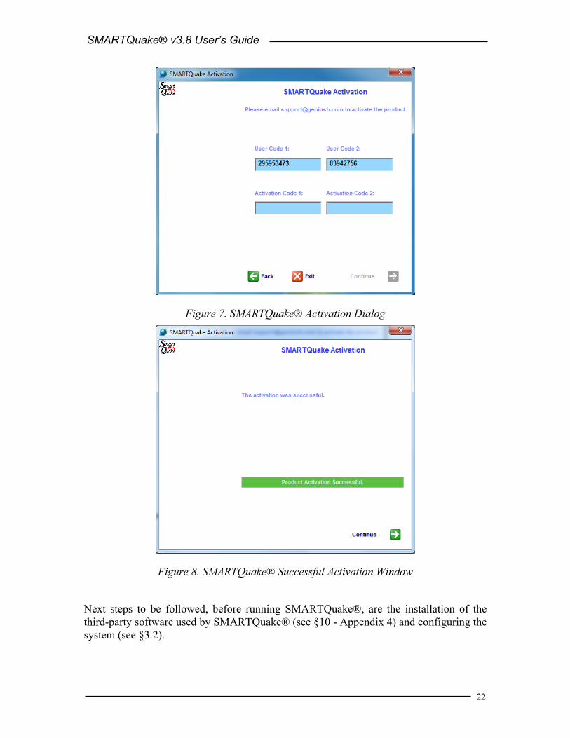
To activate SMARTQuake®, click on the ‘Activate SMARTQuake’ link and the activation dialog will open as shown in Figure 7. Submit to Geotech the two user codes displayed in this dialog. Upon receipt of the activation number(s) from the factory, go to the activation dialog and enter the activation code(s) (if only one code is received enter it as ‘Activation Code 1’), then press Continue. A window as in Figure 8 confirms a successful activation; press Continue to start the application.
After activation, SMARTQuake® application starts directly to its main window as described in the next section.
Figure 6. SMARTQuake® initial window
SMARTQuake® v3.8 User’s Guide
22
Figure 7. SMARTQuake® Activation Dialog
Figure 8. SMARTQuake® Successful Activation Window
Next steps to be followed, before running SMARTQuake®, are the installation of the third-party software used by SMARTQuake® (see §10 - Appendix 4) and configuring the system (see §3.2).

SMARTQuake® v3.8 User’s Guide
23
3 SMARTQuake® Configuration
3.1 SMARTQuake® Directories and Files SMARTQuake® has the following directory structure (created during installation):
C:\smartquake : home directory, hosting the SMARTQuake® program files. It has two subdirectories, as follows:
C:\smartquake\join – work directory for joining data files; C:\smartquake\maps – work directory for maps plotting;
C:\archive : local data archive directory. Each of its subdirectories is dedicated for storing one specific data type and/or format, as follows:
C:\archive\sud\local – velocity recordings waveforms in SUDS format (.suds files) for local events; C:\archive\sud\tele - velocity recordings waveforms in SUDS format (.suds files) for distant events; C:\archive\gse - optionally used for velocity recordings waveforms saved in GSE format (.gse files); C:\archive\sac - optionally used for velocity recordings waveforms saved in SAC format (.sac-??? files); C:\archive\loc – location, phase and daily files (.evn, .pha, .det, and .loc files);
C:\dataring : ring buffer directory, optionally used, for all raw data (velocity and acceleration) in SUDS format;
C:\SMARTMessages : real-time messages directory, used for interacting with Geotech’s SMARTGeoHub® Data Server.
Note that the input data folder holding the raw data files for SMARTQuake® is not created during installation. This folder, which is at the same time the output data folder of the data acquisition system, has to pre-exist for SMARTQuake® data processing tasks to run.
For each processed event, SMARTQuake® produces the following data files:
- The waveform file in SUDS format, stored either in the C:\archive\sud\local or in the C:\archive\sud\tele folder. This file is written in SUDS 1.51 format and contains all the velocity data channels. Its follows the same naming convention as for the input (raw) data files.

SMARTQuake® v3.8 User’s Guide
24
If SMARTGeoHub® Data Server is being used as data acquisition system, the file name is: yyyymmdd_hhMMss_network.suds, where yyyy=year, mm=month, dd=day of month, hh=hour, MM=minute, ss=second corresponding to the time stamp of the first sample in the data stream, and network is the network name (up to 7 characters).
- The file with location results (and source parameters results, optionally) stored in the C:\archive\loc folder. The file has the same name as the SUDS file, but with the extension .evn.
- The waveform file in GSE 2.0 format, optionally stored in the C:\archive\gse folder. The file contains all the velocity data channels and has the same name as the SUDS file but with the extension .gse.
- The waveform files in SAC format, optionally stored in the C:\archive\sac folder. There will be one file per data channel having the same name with the SUDS file and ‘sac-’ followed by the data channel number as the extension name.
- The daily bulletin files with event phases and location results stored in the C:\archive\loc folder. These files are named yyyymmdd.det and yyyymmdd.loc (yyyy = year, mm = month, dd = day of month) and are used by the Automatic Data Request Manager (AutoDRM). The .det file contains the P and S phases, the flag for manual or automatic location and the event filename. The .loc file contains the location parameters, the event magnitude, the location quality, the flag for manual or automatic location and the event filename.
- A plot of the earthquake epicentral map is stored in the C:\SMARTQuake folder both in PostScript format (.ps file) and GIF format (.gif file). The two plots are named epimap.ps and epimap.gif, respectively, and they always contain the epicentral map of the latest processed event.
- A plot of waveforms with picks is stored in the C:\SMARTQuake folder both in PostScript format (.ps file) and GIF format (.gif file). The two plots are named sonline.ps and sonline.gif, respectively, and they always contain the waveforms of the latest processed event.

SMARTQuake® v3.8 User’s Guide
25
3.2 Setting up SMARTQuake® A Graphical User Interface (GUI) is provided for easy configuration of SMARTQuake®.
To start the configuring process, first open SMARTQuake® by double clicking on its icon on the Desktop. From the SMARTQuake® menu, select Settings, Configure (see also §4). The following window will be displayed (Figure 9).
Figure 9. SMARTQuake® files configuration selection window
Choose to start configuration from your current settings, from the factory default parameters or from your previously saved settings in a file.
The default typical configuration (recommended) allows setting-up the most used system parameters, including all the detection and processing parameters needed to run SMARTQuake®. Some of the parameters may be displayed grayed out for information only, since they do not normally need to be changed and/or their values (as set from the factory) are critical for proper system operation.
The advanced configuration, enabled if the Advanced Configuration Mode box is checked, allows read and write access to all system parameters. It should only be used by experienced users with a thorough knowledge of the system, since altering some parameters may impede the proper functioning of the system.
In the following, the configuration windows for the default typical configuration are described.
After making the configuration input selection, the next dialog will be displayed, as shown in Figure 10.

SMARTQuake® v3.8 User’s Guide
26
Figure 10. SMARTQuake® setting selection
This is the main configuration window where seven (or eight, in Advanced configuration mode) configuration classes can be selected to address the different categories of parameters, as described in the next sections.
Pressing the Exit button results in ending the system configuration process. The following window is displayed, asking whether or not to save the SMARTQuake® settings (Figure 11).
Figure 11. SMARTQuake® save settings window
If the reply is ‘Save’, then the system configuration is updated and the parameters are copied to the control files of all the system modules. The new configuration information is saved in a file called C:\smartquake\SMARTQuake.cfg, and a copy of the old

SMARTQuake® v3.8 User’s Guide
27
configuration file is kept in C:\smartquake\SMARTQuake1.cfg. The following window will be shown, informing that SMARTQuake® has been configured (Figure 12).
Figure 12. SMARTQuake® end of configuration window
If option ‘Save As’ is chosen, the settings are saved to a new configuration file; you are prompted to enter the desired file name and location. These settings do not become effective for SMARTQuake®, but any time later they can be read in and transported to the system using the SMARTQuake® Configure command. By this mechanism, the full system configuration can be performed in more that one session. If, on the other hand, the reply is ‘Don’t Save’, the configuration process is abandoned and no changes are made to the system configuration files.

SMARTQuake® v3.8 User’s Guide
28
3.2.1 General Settings When selecting the ‘General’ button in the main configuration window, the following dialog is displayed (Figure 13):
Figure 13. SMARTQuake® General Settings window
Data Files: - Time interval to check for new raw data files
SMARTQuake® looks for newly completed data files in its input folder and, if present, it creates a list of chronologically sorted input data files. If no newly completed files are found, it waits a certain time interval, as defined by this parameter (given in seconds), before repeating the check. The recommended value is 5 seconds.
- Time interval to wait for raw data file to be closed
Before copying the newest completed file, SMARTQuake® waits this time interval (given in seconds) to make sure that the writing of the raw data file is completed. Recommended value is 1 second.
If your data acquisition system, other than SMARTGeoHub® Data Server, is not keeping a temporary extension for the file being written until it is completed, this value has to be larger than the duration of one raw data file, typically by one second.

SMARTQuake® v3.8 User’s Guide
29
- Network type: Digital or Analog
This parameter is used to set up some specific features when the network has digital telemetry. In this case, SMARTQuake® will check for existence of data gaps and will temporarily disable the channels with data gaps for detection and event analysis.
- Data acquisition mode: Continuous or Triggered
Normal operation mode is Continuous, meaning that the data acquisition system (as for example SMARTGeoHub®) is producing continuous data files with constant time length. However, if your data acquisition system works in trigger-mode and produces event files, SMARTQuake® can be set up to work in Triggered mode as well, meaning that its internal event detection algorithm will be disabled and the triggered files transferred from the data acquisition system will enter directly in the event processing stage (see Figure 4).
- Chronologically sort data files according to: Files date and time, SMART file names or IASPEI file names
It is essential for SMARTQuake® to process chronologically sorted data. The input files are ordered before being transferred to the processing directory, either according to the date and time when the file was last written to or to the file name information.
The first option, ‘Files date and time’ is designed for on-line operation, when data are generated sequentially by a continuous file data acquisition system. The second choice accommodates also off-line operation, when SMARTQuake® runs on a data set collected off-line, and there could be no relation between the data and files time stamps. This latter case depends on the files naming convention, and the options are: ‘SMART file names’ for handling files produced by the SMARTGeoHub® Data Server with the names described in §1.3 or ‘IASPEI file names’ for handling files generated by the XRTP program (IASPEI Shareware Software Library, Update of Volume 1) with names of form: YYMMDDZZ.ext, where YY = last 2-digit year, MM = month of year, DD = day of month, ZZ = a two-character combination of numbers (0 to 9) and letters (A to Z) and ext = the filename extension.
- Time length of the raw data files
Duration of the raw data files, in seconds (minimum 10 seconds, see also §1.3).
Warning: This parameter has to match the time length of the continuous files generated by the data acquisition system.
- Use FDSN station naming convention
Check this box to use FDSN station name convention, meaning that three-component stations use the same station name for all three components. Uncheck this box when unique station/channel names are used and the first three characters uniquely identify the station for all three components, while the fourth character must be different, for example the component identifier ‘z’, ‘n’ or ‘e’.

SMARTQuake® v3.8 User’s Guide
30
Data Sources:
SMARTQuake® was designed to receive its stream of continuous data files from the data acquisition system, e.g. Geotech’s SMARTGeoHub® or Intelligent Communication Processor (ICP), in SUDS format. Other input data formats are supported if an appropriate file format converter (see below) or interface module is provided (see §11 - Appendix 5). In most cases SMARTQuake® input data files are stored in a single acquisition directory (data source), as they are output by the data acquisition system.
SMARTQuake® can also accept input data from multiple sources, like sub-networks of the same seismic network, provided they are produced by similar data acquisition systems: The raw files should have the same time length and follow the same naming convention, but possibly can have different data formats. If more than one data source is present, click on the Scan button to browse through data sources, on Add to add a new data source for SMARTQuake® and edit its configuration information, or on Delete to erase the current data source from SMARTQuake® configuration. For every data source four configuration parameters can be defined: - Raw data files folder
This is the input data folder for SMARTQuake®, and also the output data folder for the data acquisition system.
- Raw data files extension
All input data files are assumed to have this file extension (max. 4 characters). - Network name
When using the SMARTGeoHub® file naming convention (see §3.1), all input data files are assumed to have this network name (up to 7 characters). Leave this field blank if other naming conventions are used.
- Program/Command to convert raw data into demultiplexed SUDS format
SMARTQuake® uses demultiplexed SUDS version 1.51 as its internal data format and also as the default output format for the event files. If the input data are already in demultiplexed SUDS format, leave this parameter blank. If, on the other hand, the input data are in another format, enter here the name of the program used to convert them into demultiplexed SUDS version 1.51. In case the conversion program needs any command line arguments enter the complete command line including all arguments except for files names. SMARTQuake® will then invoke the program/command for every input data file, adding the corresponding input and output file names as arguments. The conversion program is assumed to reside in c:\smartquake.
For example, if the input data have multiplexed SUDS format enter ‘demux’ and make sure that the Win-SUDS utility demux.exe is present in c:\smartquake.

SMARTQuake® v3.8 User’s Guide
31
SMARTGeoHub®: - Enable automatic configuration from SMARTGeoHub®
Check this box to enable SMARTQuake® automatic configuration as received from Geotech’s SMARTGeoHub® Data Server. When SMARTQuake® is working integrated with the SMARTGeoHub®, and if this option is enabled, a subset of the parameters (common to both applications) are transported automatically from SMARTGeoHub® to SMARTQuake®, first time when starting the system and for every configuration change that takes place in the SMARTGeoHub® database. The automatically configurable parameters are the following:
• Raw data files folder (for changes only) • Time length of the raw data files • Network name (for changes only) • Station name • Component name • Data channel status: active, meaning data is sent to SMARTQuake®
for that particular channel, or inactive, meaning no data but only configuration information is sent to SMARTQuake® by the SMARTGeoHub®
• Station Latitude • Station Longitude • Station Elevation • Sensor Sensitivity • Calibration period • Motion type (velocity or acceleration) • LSB • Seismometer Natural Period • Sensor Type
SMARTQuake® will read the configuration messages received from SMARTGeoHub® and reconfigure itself automatically, starting with the first data file when the new configuration becomes effective. If the reconfiguration involves changes in the data channels list (such as adding, removing or renaming data channels) SMARTQuake® will automatically perform a ‘first time start’ (see §4.1 and §4.2).
- SMARTGeoHub® configuration file path
If automatic configuration from SMARTGeoHub® is enabled, use this field to set the path (local or across the network) of the configuration messages generated by SMARTGeoHub®.

SMARTQuake® v3.8 User’s Guide
32
Continuous Data Ring Buffer: - Enable ring buffer
Check this box to enable keeping the data files in demultiplexed SUDS format in a circular data buffer (recommended) when running in continuous data acquisition mode.
- Ring buffer folder
This is the home folder for the data ring buffer, set at the time of installation to c:\dataring. This folder will host subdirectories corresponding to each of the calendar days present in the ring buffer and storing the data files recorded during that day. Each subdirectory name is given by the respective date, as follows.
If the data files have long names, as those produced by SMARTGeoHub® Data Server (see §1.3), the first 8 characters of the file name are assumed to represent the date and give the name of the day subdirectory in which that data file is kept. If the files have short file names (8 characters only), then the first 6 characters give the date and the name of the day subdirectory. For example, the data file 20020804_062253_1.suds will be stored in the ring buffer directory c:\dataring\20020804, and the data file 020804ab.sud will be stored in the ring buffer directory c:\dataring\020804.
Optionally, a second ring buffer can be activated to save data for backup purposes (e.g. on another computer on the network). In advanced configuration enter the name of the second ring buffer folder after the first one, separated by a comma (e.g. c:\dataring, z:, where c:\dataring is a local folder and z: a mapped network drive).
- Size of the ring buffer
Enter the ring buffer storage capacity in Megabytes (check also your hard disk size!). Once the buffer size is reached, SMARTQuake® erases the data of the oldest day from the buffer. If two ring buffers are active, both are maintained by SMARTQuake® using the same size limit.
Data Forwarding:
Raw data can be forwarded to another data processing system (other than SMARTQuake®), or stored for backup, after conversion into a preferred seismological format (supported formats are CSS, MiniSEED, SAC or SEG-Y) or selection of acceleration data only.
Forwarded data are never deleted by SMARTQuake® automatically, this being the responsibility of the new processing task (e.g. SMARTShake for acceleration data), or of the user (manually).
Warning: Before activating forwarding of a continuous stream of data, make sure the processing task for the newly created data set is installed and ready to run! Otherwise, the continuous data files will accumulate and fill-up the hard-disk. For system protection, data forwarding will stop if free disk space drops below 5%.

SMARTQuake® v3.8 User’s Guide
33
By default, data forwarding is inactive, and can be activated by setting the following parameters: - Output data format
Choose from the drop-list box the name of the desired output format (CSS, MiniSEED, SAC or SEG-Y), or NONE to disable data forwarding.
Acceleration data are not processed by SMARTQuake® but only saved in its ring buffer (if ring buffer option is active). By selecting SMARTShake from the drop-list box, one can enable sending of the acceleration data stream in SUDS format to SMARTShake, the real-time Strong Motion Processor (see §12 - Appendix 6).
- Output data folder
Enter here the name of the folder where to store data: acceleration data only for further processing by SMARTShake, or all raw data for any other specialized data processing task (other than SMARTQuake®). This folder is not created by SMARTQuake®, and if data forwarding is enabled it has to pre-exist in order for SMARTQuake® to run. Also make sure that this folder is the input data folder for SMARTShake (see §12 - Appendix 6 for more details) or your other data processing application.
In the first case SMARTQuake® will generate and send to SMARTShake continuous SUDS files containing acceleration data only, with the same names as the originating raw data files and with the extension ‘suda’. For example, the acceleration data extracted from the input data file 20020804_062253_1.sud (containing both velocity and acceleration data) are forwarded to SMARTShake in the file named c:\shakedata\20020804_062253_1.suda. In this example, the SMARTShake output data folder is set to c:\shakedata.
In the second case, SMARTQuake® will generate and send to your data processing application all raw data (velocity, acceleration, infrasonic, etc.) after converting them into the selected seismological format (CSS, MiniSEED, SAC or SEG-Y), typically with the same names as the originating raw data files and with a different extension (e.g. ‘segy’ for the SEG-Y data format).
The output data folder will host subdirectories corresponding to each calendar day and will store all data files recorded during that day. For all data formats excepting CSS, the day subdirectory name is given by the respective date using the same naming convention as for the ring buffer (see above). For example, the raw data from the input data file 20020804_062253_1.suds are forwarded in the SEG-Y format data file named 20020804_062253_1.segy stored in the c:\segydata\20020804 directory. In this example, the output data folder is set to c:\segydata. When the CSS data format is selected, data are saved to a CSS3.0 database in the destination data folder (see Science Applications International Corporation, 2001).
Other data conversions can be enabled in SMARTQuake® as well. Please contact Geotech Instruments for further details.
SMARTQuake® v3.8 User’s Guide
34
For information only, the name of the SMARTQuake® home directory as set at the time of the installation (see §2) is displayed in the window’s top right corner.
After changing/reviewing all parameters, click OK to keep the newly entered values or click Cancel to keep the default values and ignore parameter changes done in this configuration window. Next, the main configuration window is displayed with the option to select another configuration window or to exit the configuration process.
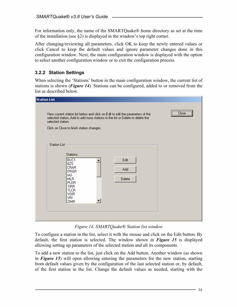
3.2.2 Station Settings When selecting the ‘Stations’ button in the main configuration window, the current list of stations is shown (Figure 14). Stations can be configured, added to or removed from the list as described below.
Figure 14. SMARTQuake® Station list window
To configure a station in the list, select it with the mouse and click on the Edit button. By default, the first station is selected. The window shown in Figure 15 is displayed allowing setting up parameters of the selected station and all its components.
To add a new station to the list, just click on the Add button. Another window (as shown in Figure 15) will open allowing entering the parameters for the new station, starting from default values given by the configuration of the last selected station or, by default, of the first station in the list. Change the default values as needed, starting with the

SMARTQuake® v3.8 User’s Guide
35
station name. Press Cancel to abandon adding the new station, or any other button to save it.
To delete a station from the list, select it with the mouse and click on the Delete button. Confirmation will be required before removing the station from the list.
Figure 15. SMARTQuake® Station Settings window
Station: - Station name
The name of the station, up to five characters (left justified); it should exactly match to the name in the data logger. For three-component stations, it is recommended to use the same station name for all three components (FDSN station name convention). However, this is not possible when input data are in the old 16-bit SUDS format without support for long station/component identifiers (version older than 1.51), and unique station/channel names (up to four characters) are required. In this case, enter in this field the channel name and make sure that its first three characters uniquely identify the station for all three components, while the fourth character must be different, for example the component identifier ‘z’, ‘n’ or ‘e’. Also, disable the use of FDSN station name convention under General Settings (see §3.2.1).

SMARTQuake® v3.8 User’s Guide
36
Site information:
Site parameters are associated with the station; they are the following: - Latitude
Enter station latitude in degrees. Check the box below if the site is in the southern hemisphere.
- Longitude
Enter station longitude in degrees. Check the box below if the site is in the western hemisphere.
- Elevation
Station elevation in meters. - 3-Component Set Name
You can associate channels into sets in the SUDS files, e.g. any station’s three components. By default, this field is left empty meaning that SMARTQuake® will automatically group together the channels with the same station name and data type (velocity or acceleration), but with different components, into a set named after the station.
If, by any reasons, customized channel association is preferred, go to Advanced configuration mode and enter the same set name (up to five characters) for the channels to be associated (SUDSPick displays only up to three channels per set).
- Moho depth
Depth of the Mohorovicic discontinuity under the station, in kilometers; this value, if present, and if its use is enabled in the velocity model configuration window, will replace, for this station only, the Mohorovicic depth value from the generic velocity model (see §3.2.5)
Component: - Component name
Any station component can be selected from the ‘component name’ list box. The component descriptor is up to three characters (left justified) and should exactly match to the name in the data logger. For vertical components, include the character ‘v’ or ‘z’ (uppercase or lowercase) in the component name. Also, for horizontal components oriented on the North-South or East-West direction, include the character ‘n’ or ‘e’ (uppercase or lowercase), respectively, in the component name. When input data are in the old 16-bit SUDS format without support for long station/component identifiers (version earlier than 1.51), the component descriptor has one single character.
To change a component’s name, select it from the list and click Edit. A dialog window opens to allow editing the name. Press OK to keep the new component name or Cancel to keep the default.

SMARTQuake® v3.8 User’s Guide
37
To add a new component, click on the Add button. A dialog window is displayed to allow entering the component name. Change the default component name (‘NEW’) and press OK to accept it.
To delete an existing component, select it with the mouse and click on the Delete button. Confirmation will be required before removing the component.
All the following parameters are associated with the component; they can be changed independently for every station’s component (data channel).
Instrument Parameters:
Instrument parameters are used by SMARTQuake® for instrument correction in ML or mb determination and source parameters inversion. Also, the instrument information is transported into GSE format, if this conversion is selected. - Sensor Sensitivity
Sensitivity for this sensor in Volts/(meters/sec) or Volts/(meters/sec2), at the calibration period (floating point value). Check the box below if the sensor is an accelerometer; otherwise a velocity sensor is assumed.
- Natural Period
Enter the natural period of the seismometer in seconds (floating point value). Check the box below if the station is broad band.
- Damping
Enter the fraction of critical damping (floating point value). - Sensor Name
Name of the sensor (maximum 6 characters); e.g., S-13 for the Geotech’s short-period seismometer model S-13.
- LSB
Digitizer LSB, corrected by any gain applied, in µVolts/digital counts (floating point value).
- Calibration Period
Calibration period in seconds (floating point value).
Based on the parameters above as entered by the user, the system sensitivity in nanometers/digital count is computed and displayed, for information purpose only.
Processing Options: - Exclude for local events detection
Check this box to declare the channel inactive for event detection only, in case of local/regional events.
- Exclude for local events detection and location
Check this box to declare the channel inactive for both event detection and location, in case of local/regional events.

SMARTQuake® v3.8 User’s Guide
38
- Exclude for teleseisms detection
Check this box to declare the channel inactive for event detection only, in case of teleseisms.
- Exclude for teleseisms detection and location
Check this box to declare the channel inactive for both event detection and location, in case of teleseisms.
- Convert to GSE format
Check this box to select this channel for conversion to GSE format. This choice is available only if the option to convert waveform event data into GSE format was selected (see §3.2.3).
Detection Filter Parameters: - Low and High frequency limits
Bandpass filter cut-off frequencies in Hertz. The filter is a 4-pole Butterworth band-pass filter applied in the time domain in the forward direction. There is no possibility to apply only high-pass or only low-pass filtering, but very high or very low cut-off frequencies may be specified. SMARTQuake® uses these parameters for filtering the data before sending them to the picker in the event detection stage.
- Do Not Filter Trace
Check this box to exclude this channel from pre-trigger filtering. - Flip Trace
Check this box to multiply by -1 the amplitudes of the current channel. If there are stations with incorrect polarity, this option will allow SMARTQuake® to output correct signs of their P arrivals and to use them in the source parameters inversion. The flipped data will not be kept in SMARTQuake® final event waveform files (original data are preserved).
Picking Filter Parameters:
The same parameters as above can be set, this time to be used by SMARTQuake® for filtering the data before sending them to the picker in the event processing stage.
After changing/reviewing all station parameters, click OK to keep the newly entered values or click Cancel to keep the default values. In either case the station list window is displayed next, with the option to select another station to be configured or to close station configuration and return to the main configuration window. Or, you may click on Next to keep the newly entered values and go to the next station in the list, or on Back to keep the newly entered values and go to the previous station in the list.

SMARTQuake® v3.8 User’s Guide
39
3.2.3 Detection and Event Settings When selecting the ‘Detection and Event’ button in the main configuration window, the next window is displayed (Figure 16).
Figure 16. SMARTQuake® Detection and Event Settings window
Detection:
For information only, the names of processing batch files that SMARTQuake® uses for event detection and processing, respectively, are shown in this window: ‘proc0’ and ‘process’. - Time window for event detection
Enter the event detection window in seconds, as defined in §1.3. - Minimum number of triggers in window for event detection
Enter the minimum number of triggered channels for declaring an event, as defined in §1.3. Enter ‘0’ to disable SMARTQuake® event detection and processing, and keep ring buffer and data forwarding functionality only (similar to SmartRing, see §13 – Appendix 7).
- Minimum number of P phases for event location
Enter the minimum number of picked P phases for entering event location stage (should be greater or equal to 3).

SMARTQuake® v3.8 User’s Guide
40
Event: - Time window to compute the predominant frequency of the signal
Time window (in seconds) used for estimating the event predominant frequency for local/distant event discrimination purposes (see §1.4).
- Threshold frequency for local/distant event discrimination
This frequency (given in Hertz) is compared to the event predominant frequency and a decision is made whether the event is considered as local or distant (events with greater predominant frequencies than the threshold value are considered local, all others are distant). Typically, a value of 3 Hz is used (see also §1.4).
- Extension of the demultiplexed SUDS files (ring buffer and events)
Waveform event files in SUDS format and the files stored in the ring buffer have this extension, fixed to ‘suds’. If the extension of the input data files differs from ‘suds’, SMARTQuake® uses the program defined in §3.2.1 to convert data into demultiplexed SUDS format. Otherwise, the input files are treated as in demultiplexed SUDS format and are passed directly to the processing stage.
- Minimum pre-event time in the event file
Based on this value (given in seconds) SMARTQuake® determines how many input data files to consider as pre-event time for event file formation (see §1.3).
- Enable on-screen display of processing results
Check this box to enable displaying the epicentral map, location results and waveforms on the screen. Event waveforms (all and the ones with picks only) are displayed only for a short time interval (10 seconds) while the event is still being processed. The epicentral map and location results are displayed as soon as they become available and are kept on screen permanently, until the next event occurs and the new plots replace the old ones. In this way, the display will show at any time information on the last occurred event.
If this option is turned off, SMARTQuake® will run as a background application and no plots will be shown on screen (but sent to the printer).
- Map plotting option: Elevation Maps or Contour Maps
If the previous option is enabled, epicentral maps are plotted as color elevation maps (see examples in Figure 1 and Figure 2) or as contours only. In the local case, the background seismicity is also plotted on the elevation map if a list file with the respective coordinates, depths and magnitudes is provided as ‘C:\SMARTQuake\catalog.dat’ (for a formatted model of this file see the file ‘catalog.dat’ included in the SMARTQuake® software distribution).
- Enable conversion of event files to GSE format
Check this box to enable conversion of waveform event data into GSE format. The GSE data will be stored in the directory c:\archive\gse (see §3.1).

SMARTQuake® v3.8 User’s Guide
41
Moreover, the GSE conversion can be activated individually for each channel (see §3.2.2).
- Enable conversion of event files to SAC format
Check this box to enable conversion of waveform event data into SAC format. The SAC data will be stored in the directory c:\archive\sac (see §3.1).
After changing/reviewing all parameters, click OK to keep the newly entered values or click Cancel to keep the default values and ignore parameter changes done in this configuration window. Next the main configuration window is displayed with the option to select another configuration window or to exit the configuration process.
3.2.4 Event Location Settings When selecting the ‘Event Location’ button in the main configuration window, the next window is displayed, giving the location parameters (Figure 17). SMARTQuake® is using a robust and reliable location program, HYPOPLUS (Oncescu and Rizescu, 1997), working in automatic mode.
Figure 17. SMARTQuake® Event Location Settings window
- The maximum hypocenter adjustment fixes the maximum changes of the spatial coordinates, in kilometers, at each iteration. The smaller the adjustment, the greater the number of iterations required to achieve convergence, but helps convergence for poorly constrained data sets. One tenth of the network “diameter” is a good value.

SMARTQuake® v3.8 User’s Guide
42
- The maximum number of iterations limits these iterations. If this number is achieved without meeting the convergence criteria specified below, the number of iterations to be printed will be output. The convergence criterion for hypocenter adjustment and the convergence criterion for origin-time are respectively tested against the changes in absolute value of the four hypocenter parameters at each iteration. If these changes are smaller or equal than the given convergence criteria, the iteration process is naturally stopped.
- The default vP/vS ratio is used to compute S-wave travel times (the velocity input model corresponds to P-waves).
- Between the maximum epicentral distance with weight 1.0 and the minimum epicentral distance with weight 0.0 a linear weight will be applied.
- When the magnitude type for local events is set to ML, an approximate Wood-Anderson magnitude will be computed (first by deconvolving the amplitude at the predominant period assuming a 1 Hz seismometer and then by convolving it with the Wood-Anderson response); when it is set to MD, the duration magnitude will be computed, according to the formula by Lee et al. (1972) for hypocenter depth less than 33 km and by Lahr et al. (1974) for greater depths. The MD formula coefficients (the constant and the coefficients expressing the dependence on the logarithm of duration and on epicentral distance) for epicenter depth less than 33 km can be set up by the user in Advanced configuration mode. For teleseisms, only the body wave magnitude mb is computed.
- The degree of confidence for the standard error computation can be set only to 68%, 95% and 99%, corresponding approximately to one, two or three standard deviations.
- A switch can be set to fix the hypocenter depth at the value given below, in kilometers.
- A switch can be set to do not use S waves when locating the event.
- A switch can be set to apply distance and azimuth weighting; the azimuth weighting is implemented as in the program HYPO71 (Lee and Lahr, 1972).
- A switch can be set to use or not the station corrections from the file CORR(TELE).DAT.
- The Abs(Res)/Median(Res) are the ratios used to decrease by a factor of two or to zero, correspondingly, the weights applied to the residuals, for local and distant events, respectively.
The program includes a ranking of the quality of location, also with separate criteria for local and distant events as defined by the user:
- For the local/regional case, the threshold values for the number of arrivals, rms of residuals, gap in azimuth and the number of S phases
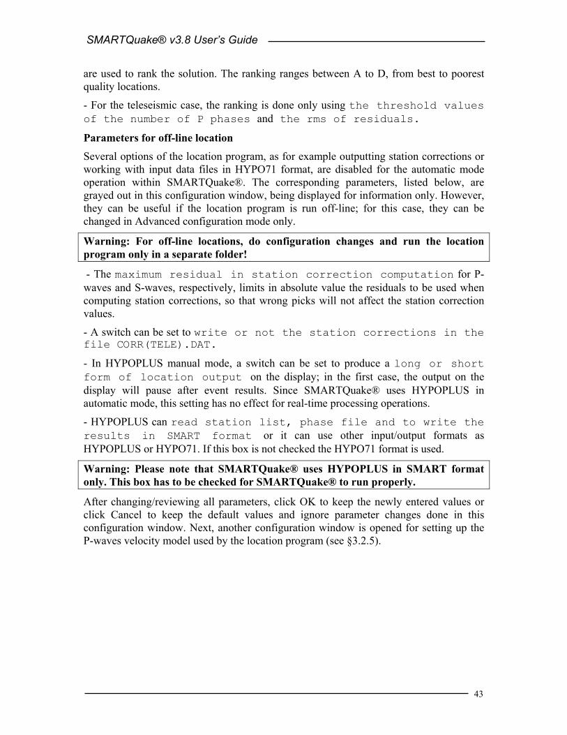
SMARTQuake® v3.8 User’s Guide
43
are used to rank the solution. The ranking ranges between A to D, from best to poorest quality locations.
- For the teleseismic case, the ranking is done only using the threshold values of the number of P phases and the rms of residuals.
Parameters for off-line location
Several options of the location program, as for example outputting station corrections or working with input data files in HYPO71 format, are disabled for the automatic mode operation within SMARTQuake®. The corresponding parameters, listed below, are grayed out in this configuration window, being displayed for information only. However, they can be useful if the location program is run off-line; for this case, they can be changed in Advanced configuration mode only.
Warning: For off-line locations, do configuration changes and run the location program only in a separate folder!
- The maximum residual in station correction computation for P-waves and S-waves, respectively, limits in absolute value the residuals to be used when computing station corrections, so that wrong picks will not affect the station correction values.
- A switch can be set to write or not the station corrections in the file CORR(TELE).DAT.
- In HYPOPLUS manual mode, a switch can be set to produce a long or short form of location output on the display; in the first case, the output on the display will pause after event results. Since SMARTQuake® uses HYPOPLUS in automatic mode, this setting has no effect for real-time processing operations.
- HYPOPLUS can read station list, phase file and to write the results in SMART format or it can use other input/output formats as HYPOPLUS or HYPO71. If this box is not checked the HYPO71 format is used.
Warning: Please note that SMARTQuake® uses HYPOPLUS in SMART format only. This box has to be checked for SMARTQuake® to run properly.
After changing/reviewing all parameters, click OK to keep the newly entered values or click Cancel to keep the default values and ignore parameter changes done in this configuration window. Next, another configuration window is opened for setting up the P-waves velocity model used by the location program (see §3.2.5).

SMARTQuake® v3.8 User’s Guide
44
3.2.5 P-Wave Velocity Model The window showed in Figure 18 allows setting up the P-waves 1-D velocity model used by the location program HYPOPLUS and by the source parameters inversion module. Each row corresponds to one layer of constant velocity; maximum 20 layers can be input. Velocity inversions are allowed.
Figure 18. SMARTQuake® P-wave Velocity Model window
The parameters to be entered are the layer thickness in kilometers, the P-wave velocity in km/sec, and the layer density in kg/m3. The layer density is a parameter used only by the seismic source inversion module, and if this function is not used the corresponding fields may be left empty. Indicate the layer below the Mohorovicic discontinuity by checking the box corresponding to that layer on the right.
Warning: The Mohorovicic discontinuity has to be marked in the model by checking the appropriate box in order for the location program to run properly.
Check the box below the velocity model to use station dependent Mohorovicic depth values, as entered in the Station/Channel information windows, to replace the Mohorovicic depth value given in this model.
After changing/reviewing the parameters, click the OK button to keep the newly entered velocity model, or click Cancel to keep the default values and ignore parameter changes
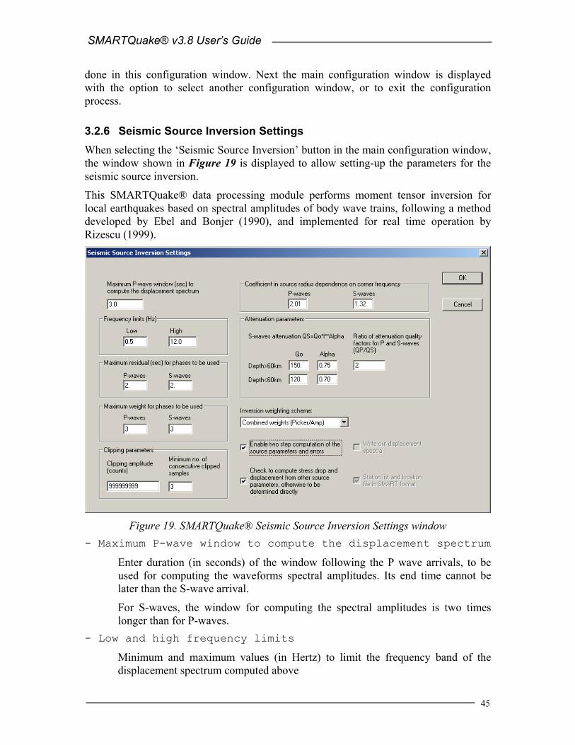
SMARTQuake® v3.8 User’s Guide
45
done in this configuration window. Next the main configuration window is displayed with the option to select another configuration window, or to exit the configuration process.
3.2.6 Seismic Source Inversion Settings When selecting the ‘Seismic Source Inversion’ button in the main configuration window, the window shown in Figure 19 is displayed to allow setting-up the parameters for the seismic source inversion.
This SMARTQuake® data processing module performs moment tensor inversion for local earthquakes based on spectral amplitudes of body wave trains, following a method developed by Ebel and Bonjer (1990), and implemented for real time operation by Rizescu (1999).
Figure 19. SMARTQuake® Seismic Source Inversion Settings window
- Maximum P-wave window to compute the displacement spectrum
Enter duration (in seconds) of the window following the P wave arrivals, to be used for computing the waveforms spectral amplitudes. Its end time cannot be later than the S-wave arrival.
For S-waves, the window for computing the spectral amplitudes is two times longer than for P-waves.
- Low and high frequency limits
Minimum and maximum values (in Hertz) to limit the frequency band of the displacement spectrum computed above

SMARTQuake® v3.8 User’s Guide
46
- Maximum residual for phases to be used
The maximum P-residual (and S-residual), in seconds, limits in absolute value the location residuals for phases to be used, so that wrong picks will not affect the inversion results.
- Maximum weight for phases to be used
The phase weight, given by the picker, ranges between 1 and 4 for very good to very poor data quality. The maximum P-weight (and S-weight) limits the weight of the observations to be used by the program, so that wrong picks will not affect the inversion results.
- Clipping parameters
SMARTQuake® will declare clipped and not use in the inversion those channels where at least minimum number of consecutive clipped samples have amplitudes exceeding the clipping amplitude. This feature is useful for 16-bit data, less likely to occur on 24-bit data.
- Coefficient in source radius dependence on corner frequency
The dependence between the source radius (r) and the corner frequency fc of the
P- or S-waves spectrum is assumed to follow the relationship: SPc
S
f ,
SP,
2 vC =r
π,
where vS is the S-waves velocity. The values of the P- and S-waves constant coefficients, CP and CS for the chosen source model are entered here.
- Attenuation parameters
This group of parameters defines the attenuation model used by SMARTQuake®. The S-waves attenuation is assumed to follow a power law: αfQQS 0= where QS is the quality factor, Q0 is the quality factor at the frequency (f) of 1 Hz and α is a constant power factor. The values of the parameters Q0 and α can be set differently for attenuation models corresponding to crustal or deep (≥ 60 km) hypocenters. The ratio of the P- and S-waves attenuation factors is assumed to be constant and is another parameter that can be set here (default is 2).
- Inversion weighting scheme
The inversion module can use: weights for the observed data as those given by the picker for the P- or S-waves, weights inverse proportional to the observed spectral amplitudes, combined weights (depending on both picker weights and amplitudes, the recommended choice) or no weights at all.
- Enable two-step computation of the source parameters and errors
The event source parameters (radius, seismic energy, Brune and apparent stress drop, displacement and seismic moment) are computed as median values over all observations. Check this box to exclude values outside one sigma interval and to re-compute the median with the reduced data set.

SMARTQuake® v3.8 User’s Guide
47
- Check to compute stress and displacement from other source parameters, otherwise to be determined directly
One can choose to compute the Brune and apparent stress drop and the displacement from the other source parameters or to determine them directly as median values of the stations observations.
Parameters for off-line source inversion
Two options of the inversion program, namely outputting computed spectra and selecting the input files format, are disabled for the on-line mode operation within SMARTQuake®. The corresponding parameters, explained below, are grayed out in this configuration window, being displayed for information only. However, they can be useful if the inversion program is run off-line; for this case, they can be changed in Advanced configuration mode only.
Warning: For off-line source inversions, do configuration changes and run the inversion program only in a separate folder (can be the same one as the off-line location folder)! - Write out displacement spectra
If this box is checked, the source inversion module outputs the computed displacement spectra. They are written in ASCII files, one per observed body-wave phase, named ‘StacoCmpW.dat’, where Staco = station name (maximum 5 characters), Cmp = component name (maximum 3 characters), W =’P’ or ‘S’ for P- or S-waves, respectively, and ‘dat’ is the file extension.
- Station list and location file in SMART format
As well as HYPOPLUS, the source inversion module can use for input/output the SMART format or it can use other formats as HYPOPLUS and HYPO71. If this box is not checked the HYPO71 format is used for the station file and the HYPOPLUS format for the location file.
Warning: Please note that SMARTQuake® uses the source inversion program in SMART format only. This box has to be checked for SMARTQuake® to run properly.
After changing/reviewing all parameters, click OK to keep the newly entered values or click Cancel to keep the default values and ignore parameter changes done in this configuration window. Next, another configuration window is opened for setting up the P-waves velocity model used by the seismic source inversion program (see §3.2.5).
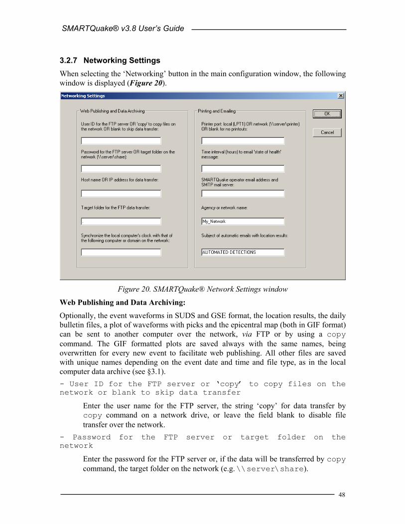
SMARTQuake® v3.8 User’s Guide
48
3.2.7 Networking Settings When selecting the ‘Networking’ button in the main configuration window, the following window is displayed (Figure 20).
Figure 20. SMARTQuake® Network Settings window
Web Publishing and Data Archiving:
Optionally, the event waveforms in SUDS and GSE format, the location results, the daily bulletin files, a plot of waveforms with picks and the epicentral map (both in GIF format) can be sent to another computer over the network, via FTP or by using a copy command. The GIF formatted plots are saved always with the same names, being overwritten for every new event to facilitate web publishing. All other files are saved with unique names depending on the event date and time and file type, as in the local computer data archive (see §3.1). - User ID for the FTP server or ‘copy’ to copy files on the network or blank to skip data transfer
Enter the user name for the FTP server, the string ‘copy’ for data transfer by copy command on a network drive, or leave the field blank to disable file transfer over the network.
- Password for the FTP server or target folder on the network
Enter the password for the FTP server or, if the data will be transferred by copy command, the target folder on the network (e.g. \\server\share).

SMARTQuake® v3.8 User’s Guide
49
- Host name or IP address for data transfer
This is the host name or the IP address of the computer where data will be transferred by FTP or ‘copy’ command. It is a required field for the FTP option. Before starting the data transfer, SMARTQuake® tests the link to this computer (by sending a ‘ping’ command) and, in case of malfunction, cancels data transfer and updates the log file c:\smartquake\DRMLOG by writing the name of the event files that failed to be transferred. If the network computer is fire walled, its firewall should be set to allow incoming echo request messages.
- Target folder for the FTP data transfer
Enter the destination directory for FTP data transfer (can be the full path or the name of a subdirectory in the FTP server home directory).
- Synchronize the local computer's clock with that of the following computer or domain on the network
Enter the name of the computer (e.g. \\computername) or domain on the network (e.g. domain.name) that SMARTQuake® will use to periodically synchronize the clock of the local computer by using the Windows system ‘net time’ command. Leave this field blank to disable synchronizing.
Printing and Emailing: - Printer port
Enter the name of the local port (e.g. lpt1) or network port (e.g. \\server\printer) where a PostScript compatible printer is connected to, or leave this field blank to disable printouts.
- Time interval to email ‘state of health’ message
A ‘state-of-health’ report is generated at this given time interval (for example, hourly or daily), and is sent by email to the system operator at the address given below. At the same time, the local computer’s clock is synchronized from time services on the network. To disable these periodically scheduled services, leave this field blank.
- SMARTQuake® operator email address and SMTP mail server
First name in this field is the email address of the system operator (e.g. [email protected]). This is the destination address for sending the ‘state-of-health’ messages, periodically and at every system start or stop. Also it is the sender address for the emails with location results produced by SMARTQuake®. The name of the SMTP mail server used for automatic email sending can be entered after the operator email address, separated by a comma. If only the operator email address is entered, the SMTP mail server name is read from the first part of the domain name in the operator email address (in the example above, the SMTP mail server is server). To disable email sending, leave this field blank.
- Agency or network name

SMARTQuake® v3.8 User’s Guide
50
This parameter allows an identification string for the agency or network (max. 18 characters) to be entered. It is written in the header of the location results. Also, it is used as sender name for automatic emails.
- Subject of automatic emails with location results
Automatic emails sent by SMARTQuake® have this subject.
After changing/reviewing all parameters, click OK to keep the newly entered values or click Cancel to keep the default values and ignore parameter changes done in this configuration window. Next the main configuration window is displayed with the option to select another configuration window or to exit the configuration process.

SMARTQuake® v3.8 User’s Guide
51
3.2.8 Messaging Settings When selecting the ‘Messaging’ button in the main configuration window, the following window is displayed (Figure 21).
It allows setting up the list of addresses and telephone numbers that SMARTQuake® uses for sending emails and SMS messages with location results. The emails are already formatted as required by some of the most important seismological centers (e.g. IDC, NEIC, EMSC, Swiss Seismological Service, etc). By default (factory settings), these fields are blank.
Figure 21. SMARTQuake® Messaging Settings window
The list of available SMARTQuake® message types is shown in this window. For every one of them the destination address list can be displayed and changed as described below. Closing this window will return to the main configuration window.
Select the first message type and press Edit to set up the list of email addresses for sending the location and/or phase messages in SMART format. The content of this type of email messages is exemplified on the first two pages of Appendixes 1 and 2, for the cases where event location is or is not available, respectively, and for local and distant earthquakes, correspondingly. The current email address list is displayed in a dialog window as shown in Figure 22.

SMARTQuake® v3.8 User’s Guide
52
Figure 22. SMARTQuake® Email Messaging Settings window for location results in
SMART format
To add a new email address to the list, click the Add button. A dialog window opens allowing you to enter the new email address; press OK to save changes or Cancel to ignore them.
To delete an existing email address from the list, select it with the mouse and click the Delete button.
To change an existing email address, select it from the list and click on the Edit button. A dialog window opens to allow editing the name; press OK to save the changes or Cancel to ignore them.
To import a list of addresses read from a text file (one email address per line, e.g. Microsoft Outlook Express address book exported as text file), click on the Import button and, when prompted, select the name of the file to be imported. Once the operation is completed the window is updated to reflect the new email address list, and the functions described above can be used to add, delete or change any entry from the list.
After changing/reviewing the list, click OK to keep the newly entered values or click Cancel to keep the default values and ignore changes done in this configuration window. Next the main messaging window is displayed with the option to select another message type or to return to the main configuration window.
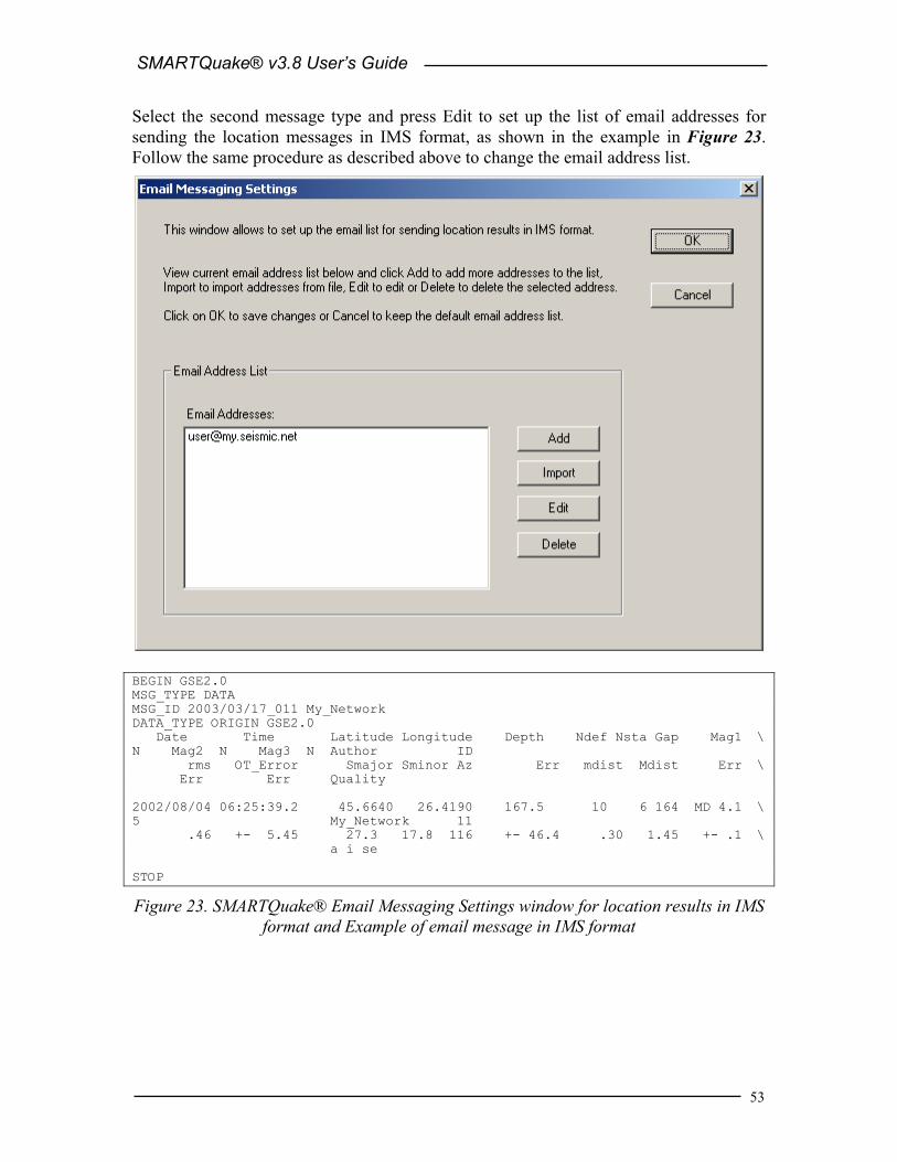
SMARTQuake® v3.8 User’s Guide
53
Select the second message type and press Edit to set up the list of email addresses for sending the location messages in IMS format, as shown in the example in Figure 23. Follow the same procedure as described above to change the email address list.
BEGIN GSE2.0 MSG_TYPE DATA MSG_ID 2003/03/17_011 My_Network DATA_TYPE ORIGIN GSE2.0 Date Time Latitude Longitude Depth Ndef Nsta Gap Mag1 \ N Mag2 N Mag3 N Author ID rms OT_Error Smajor Sminor Az Err mdist Mdist Err \ Err Err Quality 2002/08/04 06:25:39.2 45.6640 26.4190 167.5 10 6 164 MD 4.1 \ 5 My_Network 11 .46 +- 5.45 27.3 17.8 116 +- 46.4 .30 1.45 +- .1 \ a i se STOP
Figure 23. SMARTQuake® Email Messaging Settings window for location results in IMS format and Example of email message in IMS format

SMARTQuake® v3.8 User’s Guide
54
Select the third message type and press Edit to set up the list of email addresses for sending the location messages of local events with magnitudes M≥3 using a window as presented in Figure 24.
The locations are also in SMART format, as shown on the first page of Appendix 1. Follow the same procedure as described above to change the email address list.
Figure 24. SMARTQuake® Email Messaging Settings window for location results of
local events with magnitudes M≥3
Select the fourth message type and press Edit to set up the list of email addresses for sending the location messages of events with magnitudes M≥3.5 and quality rank better than D, using a window as presented in Figure 25.
The locations are in SMART format, as shown on the first page of Appendixes 1 and 2 for local and distant earthquakes, respectively. Follow the same procedure as described above to change the email address list.
Select the fifth message type and press Edit to set up the list of email addresses for sending locations results as alert messages in Swiss Seismological Service format, as shown in the example shown in Figure 26. Follow the same procedure as described above to change the email address list.

SMARTQuake® v3.8 User’s Guide
55
Figure 25. SMARTQuake® Email Messaging Settings window for location results of
events with magnitudes M≥3.5
sedz 20020804 06:25:38.739 45.66623N 26.39659E 171.72 ML 4.1 AC 0.422s N 9 G168 My_Network
Figure 26. SMARTQuake® Email Messaging Settings window for alert messages in Swiss Seismological Service format, and an example of alert message

SMARTQuake® v3.8 User’s Guide
56
Select the last message type and press Edit to set up the list of phone numbers for sending locations results of local events with magnitudes M ≥ 3 as SMS text messages, as shown in Figure 27. Follow the same procedure as described above to change the phone numbers list.
My_Network Automatic Location: 2002/08/04 6:25:39 45.66N 26.41E H=167km MD=4.1 Vrancea, Romania
Figure 27. SMARTQuake® Phone Messaging Settings window for SMS text messages, and an example of SMS text message

SMARTQuake® v3.8 User’s Guide
57
3.2.9 Regenerate Parameter Files Another useful configuration command is Regenerate parameter files, that can be started from the SMARTQuake® Settings menu (see also §4).
This command allows regenerating all SMARTQuake® parameter files based on the last saved configuration information, without making any configuration changes to the system. By executing it, the configuration information currently stored in the file SMARTQuake.cfg will be copied to the control files of all the system modules.
This command can be used if one of the SMARTQuake® control files was accidentally deleted and needs to be recreated, and also there is no need to perform any configuration changes. After execution, the window shown in Figure 28 will be displayed.
Figure 28. SMARTQuake® end of configuration window
After being configured as described in §3.2, SMARTQuake® is now ready to run (see §4).

SMARTQuake® v3.8 User’s Guide
58
4 SMARTQuake® Operation To run SMARTQuake®, double click on the SMARTQuake® icon from the Desktop. The automated processor GUI will be displayed as shown in Figure 29.
The Messages window provides information on system functioning and event detections: the date and time when different operations are performed (as for example configuring or starting/stopping data processing), as well as the date and time of the first arrival in case of detected event.
The first menu, Commands, allows commanding system actions.
The second menu, Operation, offers the possibility to perform different operations on the system’s location results and waveforms.
The third menu, Settings, gives access to the system configuration tools.
These menus are described in the next sections.
Figure 29. SMARTQuake® Messages window

SMARTQuake® v3.8 User’s Guide
59
4.1 Commands The Commands menu has the following options, as shown in Figure 30:
Figure 30. SMARTQuake® Command menu
- Start This is the command to start the SMARTQuake® processor, preserving continuity in system activities. Whenever the flow of data processing is temporarily interrupted, by stopping the processor using the ‘Stop’ command, it can be resumed, without any discontinuity in event detection and processing, by selecting ‘Start’. SMARTQuake® will start by analyzing first the oldest unprocessed data files.
- New Start This is the command necessary to be used when starting the SMARTQuake® processor for the first time, or after manually reconfiguring SMARTQuake® and any data channels were added, removed or renamed.
Whenever SMARTGeoHub® Data Server is reconfigured involving such changes in the data channels list, SMARTQuake® will automatically stop operation, reconfigure it self, and then perform a ‘New Start’. Therefore, in this case it is not necessary for the system operator to issue the ‘New Start’ command manually.
This command performs the complete reset of the data processor activities. It interrupts the continuity of event detection and causes a detection inactivity

SMARTQuake® v3.8 User’s Guide
60
period of at least two times the time length of one input data file. All temporary files that insure continuity in event detection are deleted.
- Stop This is the command to temporarily stop the automated processor. If one event has just been detected, the interruption is done only after completing all processing steps for that event file (usually only several seconds).
To resume the processing activity, one can use one of the commands ‘Start’ (which assures continuity in processing) or ‘Restart’ (which performs a full reset of the processor).
After issuing the ‘Stop’ command, please wait a few seconds, as instructed on the Messages window, for the completion of the system shutdown. A message box will inform when the system has actually stopped operation.
- Delete Ring Buffer This command deletes the entire content of the ring data buffer. When this option is selected, the user is prompted for confirmation before deleting the ring buffer.
- Move Ring Buffer This command moves the entire content of the ring data buffer to the SMARTQuake® input data folder. Subsequently, the entire data set can be processed by issuing the ‘Restart’ command. This option is in particular useful to allow re-runs of SMARTQuake® processing (in off-line mode) on same data set using different processing parameters. When this option is selected, the user is prompted for confirmation before moving the ring buffer.
- View Log A history of all messages displayed in the SMARTQuake® message window, logging system main activities like system start, stop, configuration, ring buffer clean-up or event detections, can be viewed by using this command. It is enabled only when the processor is stopped.
- Exit This is the command to exit and close all SMARTQuake® windows. It is enabled only when the processor is stopped.

SMARTQuake® v3.8 User’s Guide
61
4.2 Operation The Operation menu has the following submenu: ‘Plot Local Events’, that is an interactive operation allowing the user to display on screen (and send to the printer) an epicenter map of local events as shown in Figure 31.
The locations (using the native SMART format, as produced by SMARTQuake®) are read from one or two input data folders. Default is to use the SMARTQuake® home folder. The locations are then selected according to the event origin time, hypocenter latitude and longitude, depth, and magnitude criteria, using a dialog window as shown in Figure 32.
Each of the two sets of locations (that can be, for example, automatic locations produced by SMARTQuake® and manual locations for the same group of events) are plotted with a different symbol, red and black dots, respectively.
The background seismicity is also plotted with different symbols (yellow dots) if a list file with the coordinates, depths and magnitudes is provided as file ‘C:\SeisPlus\catalog.dat’ (for a formatted model of this file, see the file ‘catalog.dat’ included in the SMARTQuake® software distribution,).
Optionally, as set by the user, either one or both sets of locations are appended to the background seismicity list. The map is saved as a PostScript file in the SMARTQuake® home folder, with its file name reflecting the file creation date and time, like ‘epimap_2004_Mar_03_1227.ps’.
The Plot Local Events operation is available only when no automated processing activity is running - i.e., after using the ‘Stop’ command for stopping the SMARTQuake® processor.

SMARTQuake® v3.8 User’s Guide
62
Figure 31. Window with the Local Events Epicenter Map
Figure 32. Plot Local Events Dialog

SMARTQuake® v3.8 User’s Guide
63
4.3 Settings The Settings menu has the following options (Figure 33):
Figure 33. SMARTQuake® Settings menu
- Configure This is the command to start SMARTQuake® configuration. It is necessary to run this command before starting SMARTQuake® for the first time and whenever the automated processor parameters need to be changed. Before running ‘Configure’, the ‘Stop’ command has to be used for stopping the processor.
Whenever SMARTGeoHub® Data Server is reconfigured, SMARTQuake® will stop operation, reconfigure it self automatically, and then it will restart processing (by performing a ‘Start’ or a ‘Restart’, depending on what parameters have been changed). Therefore, in such cases it is not necessary for the system operator to issue the ‘Configure’ command manually.
For a detailed description of the configuring process, see §3.2.
- Regenerate Parameter Files This is the command to regenerate all SMARTQuake® parameter files, based on the last saved configuration information. This command can be used if one of the SMARTQuake® parameter files was accidentally deleted and it needs to be recreated, and there is no need to perform any configuration changes (see also §3.2.9).

SMARTQuake® v3.8 User’s Guide
64
4.4 Running SMARTQuake® When SMARTQuake® is in operation, its main program, the SMARTQuakeManager runs continuously in the background as the ‘processing manager’. It controls execution of all system tasks: data transfer from the acquisition program, check for detection, event processing, and state of health reports, as described in §1. Make sure not to accidentally close the SMARTQuakeManager window running minimized (on the Windows taskbar). Only the commands previously described (in §4.1) to stop or start the processor should be used.
While the automated processor is running as a background application, system messages are displayed in the SMARTQuake Messages window in case of event detection. Only when the ‘on-screen display of processing results’ option is enabled, the epicentral map, location results and waveforms are shown on the screen following event detection (see also §3.2.3).
When the data acquisition system (e.g. SMARTGeoHub® Data Server) is stopped for whatever reasons, and is not delivering continuous files for SMARTQuake®, it is recommended to stop SMARTQuake® as well, and to restart it when the data acquisition task has resumed, by using a ‘Restart’ command. If the interruption is very short (seconds) SMARTQuake® will attempt to pad the data with zeros to preserve continuity in event detection and processing, otherwise it will detect an inactivity period and will continue waiting for new data. Continuing to run the system without new data will not cause errors or system crashes, but it will not assure proper data continuity.
SMARTQuake® is a fully automated task and does not require special maintenance procedures to be performed by the system operator. Heartbeat messages are emailed to the system operator, so one can accurately know at any time the system state-of-health. The archive directory (containing all processing results) can be accessed locally or across the network for operations as backup and clean-up, according to the specific hardware and software system configuration.
Logging information
A log of all system messages as shown in the Messages window is kept in the file c:\smartquake\smartquake.log. Also, a log of the network failures is kept in the file c:\smartquake\drmlog and one for failed or cancelled emails in the file c:\smartquake\maillog.

SMARTQuake® v3.8 User’s Guide
65
5 SMARTQuake® Data Extraction Tool The specialized tool SMARTExtract performs data retrieval from a buffer formed by continuous files, like the SMARTQuake® ring buffer.
For example, this tool is useful to extract time windows of data that might contain events not meeting the event declaration criteria. These ‘off-line’ events (extracted by the operator) can then undergo additional, user-defined processing, similar with the events detected on-line. The retrieved waveforms are saved in different formats to a user-defined folder, and optionally can be visualized on the screen or sent to a PostScript or HP Printer Control Language compatible printer.
5.1 Installing SMARTExtract Follow the next steps to install SMARTExtract. If used to access data from the SMARTQuake® ring buffer, SMARTExtract should be installed on the same machine where SMARTQuake® is running. Choose a name for the home directory of SMARTExtract. Recommended is C:\smartextract. Then, run the self extracting archive file ‘Smartextract v3.1 install.exe’ from the Geotech’s distribution CD-ROM and, when prompted for the destination directory to unpack all files, enter the path to the local SMARTExtract directory. This procedure will create all folders and copy all files necessary to run SMARTExtract.
It is recommended that you create a shortcut on your Desktop to the C:\smartextract\SMARTExtract.exe program.
5.2 Configuring SMARTExtract A GUI is provided for easy configuration of SMARTExtract. To start the configuring process, open SMARTExtract by double clicking on its icon on the Desktop. From the SMARTExtract menu, select Settings, Configure. The window in Figure 34 will be displayed, showing the parameters to be set-up before running SMARTExtract. - Data buffer folder
This is the folder where the input data buffer is stored. To extract data from the SMARTQuake® ring buffer if its ring buffer option is active, enter here c:\dataring (see also §3.2.1).
- Single directory/Days subdirectories data buffer
The data buffer can be organized as a single directory hosting all data files, or with days subdirectories where data files recorded during one day are stored (see also §3.2.1). To extract data from the SMARTQuake® ring buffer, choose the Days subdirectories option.
- Input data files extension
All input data files are assumed to have this file extension (max. 4 characters). For the SMARTQuake® ring buffer files, this extension is set to ‘suds’.

SMARTQuake® v3.8 User’s Guide
66
Figure 34. Configuration dialog of SMARTExtract
- Output data files extension
Extracted waveforms in SUDS format will have this extension, typically ‘suds’. If the input and output data files extensions differ, SMARTExtract will assume the input format is not SUDS and will use the program defined below to convert data into demultiplexed SUDS format.
- Program/Command to convert data into demultiplexed SUDS format
SMARTExtract uses demultiplexed SUDS as the default output format for the extracted waveforms. If the input data already have this format, as it is the case when extracting data from the SMARTQuake® ring buffer, this parameter will not be used. If the input data have another format, enter here the name of the conversion program to convert them into SUDS format. In case the conversion program needs any command line arguments, enter the complete command line including all arguments except for files names. SMARTExtract will then invoke the program/command for every data file from the ring buffer, adding the corresponding input and output file names as arguments. The conversion program is assumed to reside in c:\smartextract. For example, if the ring buffer data

SMARTQuake® v3.8 User’s Guide
67
have multiplexed SUDS format set this parameter to ‘demux’, and make sure that the Win-SUDS program demux.exe is present in c:\smartextract.
- Chronologically sort data files according to:
This option tells SMARTExtract how to sort the data. The input files are ordered either according to the date and time when the file was written to the ring buffer or according to the file name information.
The first option, ‘Files date and time’ is designed for a ring buffer written on-line with data generated sequentially by a continuous file data acquisition system (like the SMARTQuake® the ring buffer). The second choice is more adequate for handling off-line data, like those coming from field stations with local recording, when there could be no relation between the data and files time stamps.
This latter case depends on the files naming convention and the options are: ‘SMART file names’ for handling files with the names described in §1.3, or ‘IASPEI file names’ for handling files generated by the XRTP program (IASPEI Shareware Software Library, Update of Volume 1) with names of form: YYMMDDZZ.WVM, where YY = last 2-digit year, MM = month, DD = day of month, ZZ = a two-character combination of numbers (0 to 9) and letters (A to Z), and WVM = the filename extension. Other supported file names are: yyyyddd_hhMMss.suds, where yyyy=year, ddd=day of year (DOY), hh=hour, MM=minute, ss=second corresponding to the time stamp of the first sample in the data stream, with the option ‘DOY file names’.
- Name of processing batch file
Following data retrieval from the ring buffer, SMARTExtract will launch this batch file (with the full pathname of the output file as first argument) to perform additional automated data processing on the extracted waveforms. Edit the batch file c:\smartextract\process1.bat to define desired processing steps (e.g. conversions, data transfer, etc.), or leave it as is after installation for no additional processing.
- Storage folder for extracted waveforms
This is the target folder for the output data files. - Printer language
Select your printer language, as PostScript or HP Printer Control Language. - Printer port
Enter the name of the local port (e.g. lpt1) or network port (e.g. \\server\printer) where your printer is connected to, or ‘nul’ to disable printouts.
After changing/reviewing all parameters, click on OK to save the newly entered parameters or on Cancel to keep the default values. This will end the SMARTExtract configuration process. SMARTExtract is now ready to run.

SMARTQuake® v3.8 User’s Guide
68
5.3 Running SMARTExtract To run SMARTExtract, double click on the SMARTExtract icon on the Desktop. The following GUI in Figure 35 will be displayed.
Figure 35. SMARTExtract GUI
The first menu, Commands, allows starting ‘Request Data’.
The second menu, Settings, allows to start the SMARTExtract configuration (see §5.2) by using the command ‘Configure’.
The SMARTExtract Messages window provides information on the program functioning, listing the different operations performed, as for example configuration or waveform extraction parameters, as well as results (see Figure 37).
When the ‘Request Data’ command is issued, the dialog window in Figure 36 is output.
The user is prompted for entering the ‘Waveform begin date and time’, and the ‘Window length’ that can be given in minutes or in seconds as selected by checking the corresponding radio button.
The program’s search is based on the information read from the data buffer list file, which enumerates the files from the data buffer together with their start and end times, and file names (one entry per line). Such a list file is generated and continuously updated by SMARTQuake® when its ring buffer option is active. In this case SMARTExtract will locate and use the list file kept by SMARTQuake®.
However, if the data buffer list file is not available for any reasons, click on the button ‘Build data buffer list’. This selection will command SMARTExtract to read the data buffer content and generate its own list file (c:\smartextract\sudslist), to be used when performing any data search.

SMARTQuake® v3.8 User’s Guide
69
Generation of the list file can be a time consuming operation if the data buffer contains many data files. Also, note that as long as there is a local file ‘sudslist’ in its home directory, SMARTExtract will use this one and will not look for the list file in the SMARTQuake® home directory. To force a search based on the SMARTQuake®’s current ring buffer list, one should delete manually the file c:\smartextract\sudslist.
To display the current list file used by SMARTExtract, click on the button ‘Show data buffer list’. The ‘Notepad’ program will be used to display the content of the list file. When finished, choose the option Exit from the File Menu to close the list file.
Figure 36. Data Request dialog of SMARTExtract
The ‘Waveform plotting mode’ can be chosen between ‘Screen’, ‘Printer’, ‘Windows Metafile’, and ‘No output’, meaning the retrieved data can be plotted on screen only, sent to a printer, output as a graphical image file in Microsoft Windows Metafile format, or just saved as raw data file in the output directory.
If data gaps are found in the ring buffer within the requested time window and the box ‘Pad data gaps with zeros’ is checked, one single SUDS file is output (or plotted) padding missing samples with the value ‘0’. Otherwise, if data padding is disabled, multiple files (or plots) are output corresponding to each data segment between gaps as retrieved from the data buffer.
The ‘Output data format’ can be selected between ‘SUDS’, ‘CSS3.0’, and ‘ASCII’, meaning the output files are written in SUDS (default), CSS3.0 or ASCII format, respectively.
The CSS3.0 data are written to a CSS3.0 database (see Science Applications International Corporation, 2001) in the .w subfolder. The .wfdisc, .sitechan and .lastid CSS tables are written to the SMARTExtract output directory.

SMARTQuake® v3.8 User’s Guide
70
The ASCII files are written in a simple ASCII (text) format, one file for each channel. The data file has one header line starting with ‘H’ followed by the initial sample time as number of seconds since 01/01/1970, 00:00:00, the sample rate, channel number and bit weight in Volts/count. The header line is followed by the data values in counts.
The ‘Data type’ can be chosen between ‘Velocity’, ‘Acceleration’, and ‘All’, to output velocity only, acceleration only or all recordings, respectively.
After entering the desired parameters, click on OK to proceed or on Exit to cancel the data search. The program extracts the selected waveforms from the data buffer and forms the output file. Then, according to user’s options, the waveforms are displayed on the screen (see Figure 37), sent to the printer, saved to the output folder in the desired data format, and finally, the user-defined automated processing is executed, if so configured.
Figure 37. The output of SMARTExtract following processing of a data request
Acknowledgement. Optionally, for epicenter map plotting and PostScript file generation, SMARTQuake® uses GMT v3.4.3 (Wessel and Smith, 2003), NetCDF v3.5.0 (University Corporation for Atmospheric Research/Unidata, 2001), GNU Awk v3.0.3 and GNU Ghostscript v7.06 (Free Software Foundation, 1997, 2003), TerrainBase (National Geophysical Data Center) and GTOPO30 (U.S. Geological Survey), ImageMagick (ImageMagick Studio, 1999-2006), GnuWin32 Enscript (Free Software Foundation, 2003), as well as a license of GSview v4.6 by Ghostgum Software (2003).

SMARTQuake® v3.8 User’s Guide
71
6 References Allen, R.V., 1978, Automatic earthquake recognition and timing from single traces: Bull.
Seism.Soc. Am., 68, p. 1521-1532.
Banfill, R., 1999. PC-SUDS Utilities Version 2.60, Banfill Software Engineering, Big Water, Utah, 180p.
Banfill, R., 2003. Win-SUDS Utilities Version 2.90, Banfill Software Engineering, Valdez, Alaska, 7p.
Ebel, J.E., Bonjer, K.-P., 1990. Moment tensor inversion of small earthquakes in southwestern Germany for the fault plane solution. Geophys. J. Int., 101, 133-146.
GSETT-2, 1990. Ad hoc group of scientific experts to consider international cooperative measures to detect and identify seismic events - Conference Room Paper 190/Rev.4, ‘Instructions for the conduct of the preparatory test of phase 3 of GSETT-2’, Sept. 1990, Geneva, Switzerland.
Incorporated Research Institutions for Seismology (IRIS), 1993. Standard for the Exchange of Earthquake Data (SEED), Reference Manual, 205 p.
Kradolfer, U., 1993. Automating the exchange of earthquake information: EOS, 74, No. 39, p. 442.
Lahr, J.C., Page, R.A. and Thomas, J.A., 1974. Catalogue of earthquakes in South Central Alaska, April-June 1972. USGS Open-File Report 74-648, 75p.
Lee, W.H.K., Bennett, R.E. and Meagher, K.L., 1972. A method of estimating magnitude of local earthquakes from signal duration. USGS Open-File Report 72-274, 67p.
Lee, W.H.K. and Lahr, J.C., 1972. HYPO71: A computer program for determining hypocenter, magnitude, and first motion pattern of local earthquakes. U. S. Geological Survey Open File Report, 100p.
Oncescu, M.C. and Rizescu, M., 1994. Conversion program package for seismological digital data on PCs. Computer & Geosciences, 20, p. 193-196.
Oncescu, M.C., Rizescu, M. and Bonjer, K.P., 1996. SAPS - A completely automated and networked seismological acquisition and processing system. Computer & Geosciences, 22, p. 89-97.
Oncescu, M.C., Rizescu, M., 1997. SAPS v3.0 - Seismological Acquisition and Processing System, User’s Guide, Karlsruhe, 82p.
Oncescu, M.C. and Rizescu, M., 1997. CONVSEIS v4.7 - Conversion program package for seismological data on PCs, IASPEI Software Shareware Library, Karlsruhe, 63p.
Rizescu, M., 1999. A completely automated system for seismological data acquisition, processing and exchange, PhD Thesis, Institute for Atomic Physics, Bucuresti, 219 p.
Science Applications International Corporation, 2001. IDC5.1.1Rev3 - IDC Documentation Database Schema, Revision 3, SAIC-01/3052, Veridian Systems.

SMARTQuake® v3.8 User’s Guide
72
Tapley, W.C. and Tull, J.E., 1991. SAC - Seismic Analysis Code: User’s manual, Rev.3, Lawrence Livermore National Laboratory, Livermore, California.
Ward, P., 1989. SUDS - Seismic Unified Data System. USGS Open-File Report 89-188, Denver, Colorado.

SMARTQuake® v3.8 User’s Guide
73
7 Appendix 1 – SMARTQuake® Local Event Output SMARTQuake® output for a local event, as displayed on the screen and optionally sent to the printer, is shown in Figure 38, Figure 39, Figure 40, Figure 41 and Figure 42. Since most of the output parameters are self-explanatory, only a subset of them is explained in the following:
7.1 Location and source parameters for a local earthquake Location parameters
Q: location quality (from A to D); NL: number of phases used in the location; NM: number of magnitude observations used to compute event magnitude; GAP: maximum azimuth gap not covered by stations, in degrees; IT: number of iterations needed to achieve convergence; DEL: epicentral distance in kilometers; AZM: station azimuth measured clockwise from the North direction, in degrees; EMG: emergence angle at the focus, in degrees, measured from the downward vertical; INT: requested (input) and computed (output) wave branch, in the first and second
column, respectively, as follows: 0 = minimum travel time ray; 1 = direct wave; positive integer = index of interface along which the wave was refracted; negative integer = in absolute value, index of interface at which the wave was reflected.
O-C: residual (observed minus computed) travel time (followed by the ‘*’ sign when the respective observation is eliminated from location);
WT: weight of the observation; AMP: amplitude in nanometers (output only if Wood-Anderson magnitude is selected); TAU: event duration in seconds; MAG: station magnitude; INFO: diagonal element of the information density matrix, showing the contribution of
each observation to the computed solution.
Source parameters
NP1: azimuth, dip and slip angles of the first nodal plane, in degrees; NP2: azimuth, dip and slip angles of the second nodal plane, in degrees; P: azimuth and dip angles of the moment tensor principal P axis, in degrees; N: azimuth and dip angles of the moment tensor principal N axis, in degrees; T: azimuth and dip angles of the moment tensor principal T axis, in degrees; NP: number of P-waves observations used in moment tensor inversion; EPS: deviation from the double-couple moment tensor model; M0: total seismic moment, in Nm; MW: moment magnitude; STRESS-DROP/APP: Brune and apparent stress-drop, respectively, in MPa; ENERGY: seismic energy, in Joule; ND: Number of observations (P- and S-waves) used for computing source parameters.

SMARTQuake® v3.8 User’s Guide
74
Figure 38. Page 1 for a local event: the location information and source parameters
results
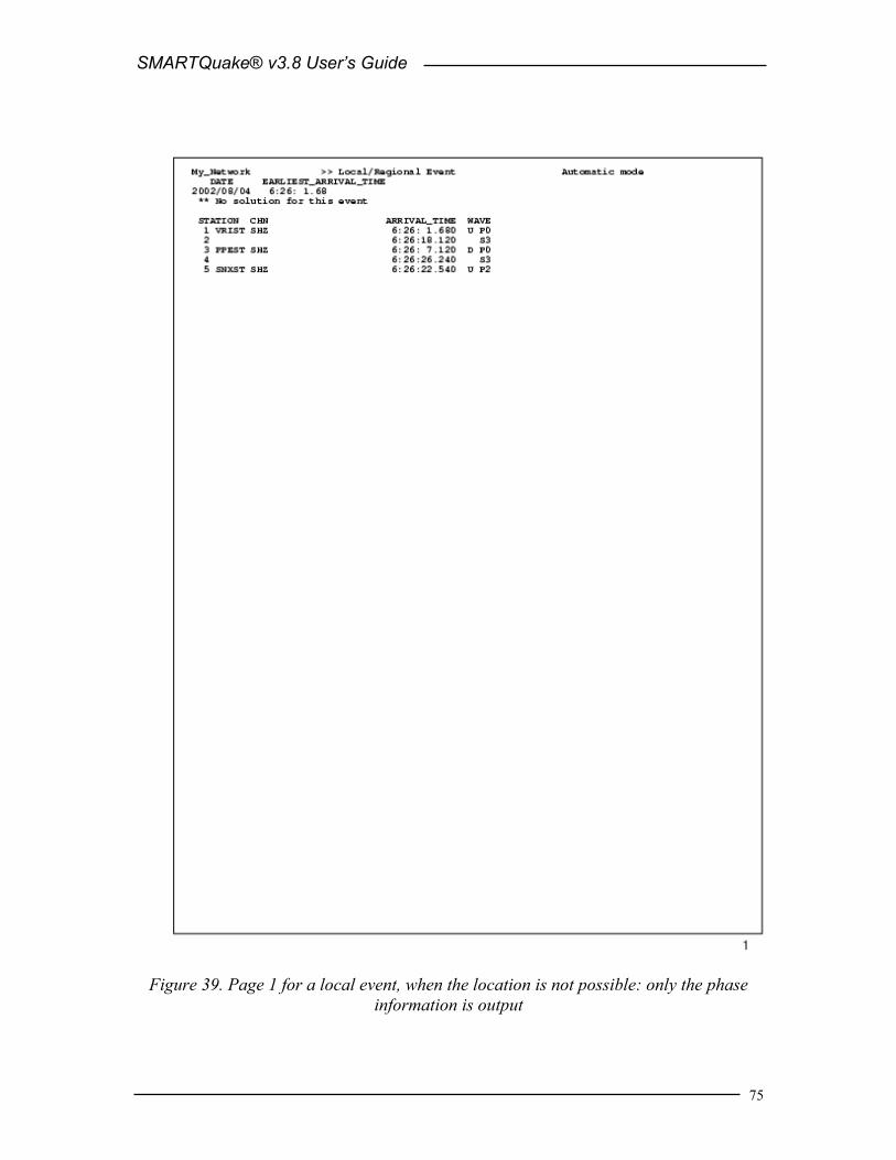
SMARTQuake® v3.8 User’s Guide
75
Figure 39. Page 1 for a local event, when the location is not possible: only the phase
information is output

SMARTQuake® v3.8 User’s Guide
76
Figure 40. Page 2 for a local event: the real-time epicentral map, showing the location
parameters and the fault plane solution in the legend and insert, respectively

SMARTQuake® v3.8 User’s Guide
77
Figure 41. Page 3 for a local event: waveforms of the picked data channels

SMARTQuake® v3.8 User’s Guide
78
Figure 42. Page 4 for a local event: waveforms of all data channels

SMARTQuake® v3.8 User’s Guide
79
8 Appendix 2 – SMARTQuake® Distant Event Output SMARTQuake® output for a distant event, as it is displayed on the screen and optionally sent to the printer, is shown in Figure 43, Figure 44, Figure 45, Figure 46 and Figure 47. Since most of the output parameters are self-explanatory, only a subset of them is explained in the following:
8.1 Location parameters for a distant earthquake Q: location quality (from A to D); DEPTH: fixed to zero; NL: number of phases used in the location; NM: number of magnitude observations used to compute event magnitude; BAZ: backazimuth angle, in degrees; DELTA: epicentral distance, in degrees; ERH: error in the epicenter position, in kilometers; O-C: residual (observed minus computed) travel time (followed by the ‘*’ sign
when the respective observation is eliminated from location); WT: weight of the observation; AMP: amplitude in nanometers; TAU: not used; mb: station magnitude; INFO: diagonal element of the information density matrix, showing the
contribution of each observation to the computed solution.

SMARTQuake® v3.8 User’s Guide
80
Figure 43. Page 1 for a distant event: the location information

SMARTQuake® v3.8 User’s Guide
81
Figure 44. Page 1 for a distant event, when the location is not possible: only the phase
information is output

SMARTQuake® v3.8 User’s Guide
82
Figure 45. Page 2 for a distant event: the real-time epicentral map, showing the location parameters in the legend

SMARTQuake® v3.8 User’s Guide
83
Figure 46. Page 3 for a distant event: waveforms of the picked data channels

SMARTQuake® v3.8 User’s Guide
84
Figure 47. Page 4 for a distant event: waveforms of all data channels

SMARTQuake® v3.8 User’s Guide
85
9 Appendix 3 – SMARTQuake® Interface to Live Internet Seismic Server - LISS (if this option is present)
SMARTQuake® can make available its stream of continuous data to the Internet by using the USGS Live Internet Seismic Server protocol (LISS). An optional module of SMARTQuake®, SUDS2LISS data server, processes incoming data in the SUDS ring buffer and streams them out formatted as MiniSEED data (data-only SEED, IRIS, 1993) to LISS client applications. It supports multiple simultaneous connections from different clients and hosts.
9.1 Installation If this option was chosen, the SUDS2LISS data server is installed as part of SMARTQuake® installation, either at the factory or from the Geotech’s SMARTQuake® CD (see §2), to the SMARTQuake® home directory (c:\smartquake). It is recommended that you create a shortcut on your Desktop to the c:\smartquake\suds2liss.exe program, named e.g. “LISS Server”. Go to the shortcut properties and select the option to be run minimized.
9.2 Configuration The SUDS2LISS data feed server is configurable by editing the file suds2liss.conf in c:\smartquake. An example of the configuration file is given below. # $Id: suds2liss.conf,v 1.8 2003/03/23 00:49:51 cvs Exp $ # Copyright (C) 2003 - Geotech Instruments, LLC. - All rights reserved. # Configuration file for SUDS2LISS version 1.0.0 or later. # Defaults for each entry are shown in ()
Log { File c:\smartquake\suds2liss.log Level normal # 'quiet', ('normal'), 'verbose, or 'debug' }
# LISS station feed server settings Server { Endpoint *:4002 # Listen at this endpoint, '*'=all interfaces (*:4002) MaxClients 8 # Maximum number of simultaneous clients (8) QueueDepth 1024 # Client queue depth as packets (1024) WriteTimeout "30 seconds" # Client write timeout ("30 seconds") }
# SUDS data ring and Mini-SEED options Backend { RecordSize 512 # MiniSEED record size in bytes 256, (512), or 4096 TimeTearFactor 2.0 # A time tear will be defined as a discontinuity # greater than +/- sampling period * TimeTearFactor (0.5) IndexFile c:\smartquake\sudslist BasePath c:\dataring }
Figure 48. Example of the suds2liss.conf configuration file
The log file, index file and base path entries have to be set as for the host SMARTQuake® system. The log file, used to output logging information on active connections and data flow, is typically named c:\smartquake\suds2liss.log.

SMARTQuake® v3.8 User’s Guide
86
The index file, used by SMARTQuake® to store the SUDS ring buffer content, is named c:\smartquake\sudslist. The base path designates the home folder of the SMARTQuake® ring buffer, which is c:\dataring.
For all other entries it is recommendable to keep the default values.
Each LISS client is identified by its IP address and port number separated by a colon. Allowed clients can be specified by entering their IP addresses, or using the default (asterisk) will allow any connection.
The MiniSEED record size parameter dictates the data server latency. The three possible values of 256, 512 and 4096 bytes correspond, given the data compression used, to packet sizes of approximately 100, 200 and 8000 samples, respectively. For example, for sensors running at 100 sps sampling rate, using the default record size value of 512 will result in a MIniSEED packet length of 2 seconds.
9.3 Running SUDS2LISS To start SUDS2LISS, double click on the LISS Server icon from the Desktop. The server will activate in a minimized window and start processing every new data written to the SMARTQuake® ring buffer. SMARTQuake® needs to be running, with the ring buffer option enabled (see §3.2.1).
Once the data server is running, client applications using the USGS LISS protocol, like USGS dumpseed or seedforker (the LISS server) on Linux and Solaris platforms, can connect to it in order to capture, examine or forward the stream of MiniSEED data. When setting up any client connection to the SUD2LISS server, one has to use the hostname (IP address or DNS name) of the SMARTQuake® computer and the port number that the server is listening to (4002).
As long as the LISS Server is running, the MiniSEED data stream is available for incoming connections on the Internet. To close the server, simply close the LISS Server window.

SMARTQuake® v3.8 User’s Guide
87
10 Appendix 4 – Installation of third-party software optionally used by SMARTQuake®and SMARTShake
10.1 The Generic Mapping Tools (GMT)
10.1.1 GMT Installation For information on obtaining and installing the GMT software, visit the GMT web site http://gmt.soest.hawaii.edu. The GMT package is available via anonymous ftp from several servers; from any of them (e.g. SOEST, Dept of Geology & Geophysics, Honolulu, Hawaii) download the archives for Windows (*.zip files):
GMT_exe.zip GMT_full.zip GMT_high.zip GMT_man.zip GMT_pdf.zip GMT_progs.zip GMT_ps.zip GMT_scripts.zip GMT_share.zip GMT_suppl.zip GMT_suppl_exe.zip GMT_tut.zip GMT_web.zip
Install GMT by uncompressing all the archives to the folder c:\gmt, preserving the original directory structure.
10.1.2 GMT Customization GTOPO30 digital elevation models and customized GMT configuration files for your geographical region of interest can be distributed by the factory on the SMARTQuake® CD. From the root directory of this distribution CD, run the self extracting archive file ‘gmt dem.exe’. When prompted, enter the destination directory to unpack all files as ‘c:\gmt’ and confirm overwriting the file grdraster.info. This procedure will install all files necessary to the GMT directory c:\gmt\share\dbase.
10.2 NetCDF The precompiled NetCDF library for Windows is needed by GMT. It is also available on the GMT ftp sites. Download the file: Netcdf-3.5.0.win32bin.zip. Install NetCDF by uncompressing this archive to the target folder c:\netcdf.

SMARTQuake® v3.8 User’s Guide
88
10.3 GNU awk The GMT scripts utilize GNU awk that is also available from all GMT ftp sites. Download the file: gawk303x.zip. Install GAWK by uncompressing the zip archive to the folder c:\gnu.
10.4 Ghostscript For information on obtaining and installing the Ghostscript software, visit the web site http://www.cs.wisc.edu/~ghost. Download the latest GNU Ghostscript release for Windows (version 7.06 or later) from any of the linked GNU distribution sites, e.g.: ftp://mirror.cs.wisc.edu/pub/mirrors/ghost/gnu. To install the software, run the self-extractable archive and accept the default settings during the setup.
10.5 System environment variables From Control Panel/System Properties/Advanced/Environment Variables, set the following new System Variables:
Variable Value GMTHOME c:\gmt NETCDF c:\netcdf
Also, edit the following existing System Variables and add the values:
Variable Value to add INCLUDE %NETCDF%\INCLUDE LIB %NETCDF%\LIB;%GMTHOME%\LIB PATH c:\gmt\bin;c:\netcdf\bin;c:\gnu\bin;
c:\Program Files\Ghostgum\gsview
10.6 GSview
10.6.1 GSview Installation For information on obtaining and installing the GSview software, visit the web site http://www.cs.wisc.edu/~ghost.
A license for GSview is provided on the Geotech’s SMARTQuake® CD. To install the software, run the self-extractable archive ‘gsv44w32.exe’ and accept the default settings during the setup. Run GSView and, when seeing the registration reminder, select Register Now and enter registration details provided by Geotech together with SMARTQuake® license key.
10.6.2 GSview Customization Optionally, SMARTQuake® displays on the screen epicentral maps and location results of the processed earthquakes. To customize the appearance of these plots on the screen, follow the next steps:

SMARTQuake® v3.8 User’s Guide
89
Go to the SMARTQuake® home folder (e.g. c:\smartquake) and from a command window run the command: customize_gsview.bat
Two demo plots will be displayed on screen, one at a time, the first one showing an epicentral map and the second one a plot with location results. For each plot select the desired position, size and zoom; when ready, close Gsview and the settings will be saved for future use by SMARTQuake®. When customizing the appearance, keep in mind that during normal operation both plots should be visible at the same time (SMARTQuake® will display them simultaneously).
Settings are saved in the files gsview32.map and gsview32.loc, in the folder given by the system environment variable “userprofile” (usually set as c:\Documents and Settings\Username).
10.7 ImageMagick For information on obtaining and installing the ImageMagick software, visit the web site http://www.imagemagick.org. Download the latest ImageMagick Windows Binary Release from this web site. To install the software, run the self-extractable archive and accept the default settings during the setup.
10.8 Enscript Enscript is one of the Win32 versions of the GNU tools, GnuWin32. For information on obtaining and installing the Enscript software, visit the web site http://sourceforge.net/projects/gnuwin32/. Download the latest Enscript Windows Binary Release from this web site. To install the software, run the self-extractable archive and accept the default settings during the setup.

SMARTQuake® v3.8 User’s Guide
90
(Page Intentionally Left Blank)

SMARTQuake® v3.8 User’s Guide
91
11 Appendix 5 – SMARTQuake® Interface to the ICP system with SEISAN files recording (if this option is present)
SMARTQuake® was designed to receive its stream of continuous data from the Geotech’s SMARTGeoHub® or Intelligent Communication Processor (ICP) in SUDS format (recommended). However, if the user prefers to run the ICP system with continuous file recording in SEISAN format, an optional interface module of SMARTQuake®, Sei2Quake, can process incoming SEISAN data in the ICP ring buffer and stream them out formatted as SUDS data in (possibly shorter) continuous files to SMARTQuake® applications.
11.1 Installation If pre-installed at the factory, this section can be skipped.
If this option was chosen, uncompress the content of the archive ‘Sei2Quake.zip’ from the Geotech’s SMARTQuake® CD to the SMARTQuake® home directory (c:\smartquake). Ensure that all files and the empty temp directory from the archive are extracted. When prompted, confirm overwriting the files filtsud.exe and sudschk.exe.
The Cronos Hourglass service is used to schedule the operation of Sei2Quake. This scheduler is licensed from Redsword Corporation.
If Cronos Hourglass previously installed and running on your computer:
If Cronos Hourglass was already previously installed and running to schedule the operation of other tasks on your computer (like AutoDRM), just open the file cronos.tab in the folder where the cronos software is located, and add the following line: P 01 00 EVERYDAY 1 January c:\smartquake\sei2quake.exe
This change will not enter into effect until you stop and then restart cronos by using the command cronos load from the command prompt.
If Cronos Hourglass not installed on your computer:
Install and configure cronos as follows:
1. At the command prompt go to directory c:\smartquake, where the Cronos Hourglass files are stored, and enter: cronos install. This installs the program as a Windows system service.
2. Go to Control Panel, Administrative Tools, Services, and set the Properties for the Cronos Hourglass as follows: “Startup Type: Automatic”, and “Log On As: This Account” (enter the user account name and password as needed). For more information on how to install and configure cronos, refer to the c:\smartquake\cronos_readme.txt file.

SMARTQuake® v3.8 User’s Guide
92
11.2 Configuration The Sei2Quake module is configurable by editing the file sei2quake.inp in c:\smartquake. An example of the configuration file is given below. ; Working directory (must have a subfolder 'temp') c:\smartquake ; Directory where ICP data are stored \\icppc\icpdata ; Directory where Suds data are stored c:\rawdata ; Size of the ICP data file (minutes) 15 ; Size of the Suds data file (seconds); must divide size of ICP data file (in secs) evenly 100 ; Maximum buffer (hours) behind real time for converting the data at startup 2
Figure 49. Example of the sei2quake.inp configuration file
The working directory is the SMARTQuake® home directory (c:\smartquake).
The second parameter is the output data folder (local or on the network) for the ICP data acquisition system.
The third entry is the input data folder for SMARTQuake®, and has to match the Raw data files folder parameter set in the SMARTQuake® configuration (see §3.2.1).
Next entries are the durations (in minutes) for the continuous SEISAN files output by the ICP system, and the durations (in seconds) for the SUDS files to be input to SMARTQuake™; this last parameter has to match the Time length of the raw data files parameter set in the SMARTQuake® configuration (see §3.2.1).
The last parameter in file sei2quake.inp sets the maximum duration of the data buffer to be converted from SEISAN to SUDS format when first starting Sei2Quake. A large value of this parameter will delay the SMARTQuake® system catching up with real-time operation.
11.3 Running Sei2Quake To start Sei2Quake, at the command prompt go to directory where Cronos Hourglass software is located (c:\smartquake) and enter: cronos start. This command starts the cronos service that schedules the automatic run of Sei2Quake. At each system start the service will restart automatically.
To stop Sei2Quake, at the command prompt go to directory where Cronos Hourglass is located (c:\smartquake) and enter: cronos stop. This command will stop cronos so that no any new Sei2Quake processes will be started. However, the ongoing processes, in case that some Sei2Quake operations are in progress, will be continued until completion.
To see if Sei2Quake is up and running, go to My Computer, Control Panel, Administrative Tools, Services, and check if Cronos Hourglass status is ‘Started’.

SMARTQuake® v3.8 User’s Guide
93
While Sei2Quake is running, different applications will be launched and can be seen in the Taskbar. Sei2Quake monitors and reads any new SEISAN continuous files output by the ICP system, waiting for the completion of the newest file that is being written. As consequence, the delay to real-time is given by the duration of the SEISAN data file and setting the ICP data acquisition system to run with minimum duration for continuous files recording (15 minutes) is recommended.
All SEISAN files are kept in the ICP output data folder (no files are erased by Sei2Quake). The data are input as SUDS continuous files of shorter duration, as requested by the user, to SMARTQuake®.
General rules apply for SMARTQuake® configuration and operation when working together with Sei2Quake (no special settings are required). While SMARTQuake® is running, it handles new data as soon as they become available from the ICP system via Sei2Quake, to perform automated event detection and processing.

SMARTQuake® v3.8 User’s Guide
94
(Page Intentionally Left Blank)

SMARTQuake® v3.8 User’s Guide
95
12 Appendix 6 – SMARTShake Strong Motion Processor (if this option is present)
12.1 SMARTShake Overview SMARTShake is a program package designed to perform high quality, fully automated earthquake strong motion data processing. It is a modular, easily extendable, specialized system working in a Windows environment, available as a stand-alone product or integrated with Geotech’s SMART Series Data Server, SMARTGeoHub® or Automated Earthquake Data Processor, SMARTQuake®.
SMARTShake starts from a stream of continuous acceleration data files in SUDS format from the data acquisition system, either from SMARTGeoHub® or from SMARTQuake®. The input data files are read from a single directory, and can have any names but a common file extension. If SMARTGeoHub® Data Server is being used as data acquisition system, the file name is: yyyymmdd_hhMMss_network.sud, where yyyy=year, mm=month, dd=day of month, hh=hour, MM=minute, ss=second corresponding to the time stamp of the first sample in the data stream, and network is the network name (up to 7 characters). Same file name, but with the extension ‘suda’ is used if the data are received from SMARTQuake®.
SMARTShake performs the following processing operations, in quasi real-time:
• Optional storage of raw data files into a circular buffer
• Strong motion event selection based on a threshold detection algorithm
• Extraction of strong motion event waveforms
• Reading of the Peak Ground Acceleration (PGA) at the recording sites on maximum horizontal components
• Optional filtering of the acceleration data and generating Filtered Peak Ground Acceleration (FPGA)
• Gridding of the observed ground shaking data values using a continuous curvature surface gridding algorithm
• Contouring of the (F)PGA data points
• Generation of 3-D perspective color Shake Maps with isolines of equal (F)PGA values superposed on the regional topography
• (F)PGA Shake Maps plotting and Web publishing
• Optional computation of Arias Intensities and Cumulative Absolute Velocities with the same map generation, plotting, and Web publishing (not yet implemented)
• Dissemination by email of lower resolution maps (not yet implemented)

SMARTQuake® v3.8 User’s Guide
96
An example of a Shake Map generated by SMARTShake is given in Figure 50.
Figure 50. Example of Shake Map output by SMARTShake Strong Motion Processor
12.2 SMARTShake Installation If pre-installed at the factory, this section can be skipped.
Choose a name for the home directory of SMARTShake. Recommended is C:\smartshake. Then, set a new system environment variable to the name of the chosen home directory. In the following, it will be assumed that the home directory for the SMARTShake is C:\smartshake.
The steps to set up the environment variable are the following:
- Go to Control Panel, System, Advanced, Environment Variables, and set a New System Variable with the name “SMARTSHAKEHOME” and the value “C:\smartshake”.
Then, run the Install program from the SMARTShake directory of Geotech’s distribution CD-ROM. This procedure will create all folders and will copy all files necessary to run SMARTShake.

SMARTQuake® v3.8 User’s Guide
97
When running Install, a window like the following will be displayed on screen (Figure 51). Click on OK to continue installation.
Figure 51. SMARTShake installation window
Then, the window shown in Figure 52 is displayed, listing the names of the folders that will be created, including the SMARTShake home directory. Click on Next to continue or Exit to cancel installation procedure.
Figure 52. SMARTShake directories window
A new window is displayed informing that SMARTShake files will be copied on your machine (Figure 53). Click on OK to continue.

SMARTQuake® v3.8 User’s Guide
98
Figure 53. SMARTShake files install window
After all the files are successfully copied the following message is displayed, as the installation procedure has now been completed (Figure 54).
Figure 54. SMARTShake end of installation window
It is recommended that you create a shortcut on your Desktop to the C:\smartshake\SMARTShake.exe program. Also, to insure that SMARTShake restarts automatically after each computer reboot, add a shortcut for the C:\smartshake\SMARTShake_auto.cmd command file to the Startup folder. Next steps to be followed, before running SMARTShake, are the installation of the third-party software used by SMARTShake (same as the one used by SMARTQuake®, see §10 -Appendix 4) and configuring the system.
12.3 SMARTShake Files and Directories SMARTShake has the following directory structure (created during installation):
C:\smartshake - home directory for SMARTShake program files. It has one subdirectory, C:\smartshake\join, used as work directory for joining data files.
C:\archive - local data archive directory. Each of its subdirectories is dedicated for storing one specific data type and/or format, as follows:
C:\archive\sud\local - acceleration recordings waveforms in SUDS format (.suda files) for local events;

SMARTQuake® v3.8 User’s Guide
99
C:\archive\maps - Shake Maps saved in PostScript format (.ps files) and GIF format (.gif files).
If both SMARTQuake® and SMARTShake are running on the same computer, same local data archive directory can be used.
C:\dataring - ring buffer directory, optionally used, for raw acceleration data in SUDS format;
When running both SMARTQuake® and SMARTShake it is recommended to enable the ring buffer option only in SMARTQuake®. Do not use same ring buffer directory on the same computer for both applications!
C:\SMARTMessages : real-time messages directory, optionally used for automatic configuration from Geotech’s SMARTGeoHub® Data Server. When running both SMARTQuake® and SMARTShake the automatic configuration from SMARTGeoHub® can be used only for SMARTQuake®.
Note that the input data folder holding the raw data files for SMARTShake is not created during installation. This folder, which is either the output data folder of the data acquisition system (like SMARTGeoHub®) or the forwarding data folder from another data processing system (like SMARTQuake®) has to pre-exist in order for the SMARTShake data processing tasks to run.
For each processed event, SMARTShake produces the following data files:
- The waveform file in SUDS format, stored in the C:\archive\sud\local folder. This file is written in SUDS 1.51 format and contains all the acceleration data channels. Its follows the same naming convention as for the input (raw) data files.
If SMARTGeoHub® Data Server is being used as data acquisition system, the file name is: yyyymmdd_hhMMss_network.suda, where yyyy=year, mm=month, dd=day of month, hh=hour, MM=minute, ss=second corresponding to the time stamp of the first sample, and network is the network name (up to 7 characters).
- The text file with Shake Maps results is stored in the C:\archive\maps folder, having same name as the SUDS file, but with the extension .txt. The file contains a list of channels with station and channel name, station latitude, longitude, recorded Peak Ground Acceleration (PGA) in centimeters/sec2, corresponding Intensity, and its date and time. For three component stations, the horizontal component with the maximum PGA value is output. If the Filtered PGA map is generated, the file also contains similar results determined on the filtered waveforms, this time with the Filtered Peak Ground Acceleration (FPGA) in centimeters/sec2 and its corresponding Intensity, and the filter frequency (the middle of the filter bandpass). An example of a SMARTShake results file is shown in Figure 64.
- PGA Shake Map files are stored in the C:\archive\maps folder. They have the same name as the SUDS file, followed by .PGA and the extension .ps or .gif for PostScript and GIF formatted files, respectively. A copy of the GIF formatted file with

SMARTQuake® v3.8 User’s Guide
100
the name pgamap.gif is stored in the c:\smartshake folder, and is optionally transferred on another computer on the network, e.g. for web publishing. The file pgamap.gif always contains the PGA Shake Map for the latest processed event.
- Intensity Shake Map files (optional) are also stored in the C:\archive\maps folder. They have the same name as the SUDS file, followed by .INT and the extension .ps or .gif for PostScript and GIF formatted files, respectively. A copy of the GIF formatted file with the name intmap.gif is stored in the c:\smartshake folder, and is optionally transferred on another computer on the network, e.g. for web publishing. The file intmap.gif always contains the Intensity Shake Map for the latest processed event.
- Filtered PGA Shake Map files (optional) are also stored in the C:\archive\maps folder. They have the same name as the SUDS file, followed by .FPGA and the extension .ps or .gif for PostScript and GIF formatted files, respectively. A copy of the GIF formatted file with the name fpgamap.gif is stored in the c:\smartshake folder, and is optionally transferred on another computer on the network, e.g. for web publishing. The file fpgamap.gif always contains the FPGA Shake Map for the latest processed event.
12.4 Setting up SMARTShake A Graphical User Interface (GUI) is provided for easy configuration of SMARTShake. To start the configuring process, open SMARTShake by double clicking on its icon on the Desktop. From the main menu, select Settings, Configure, and a window like in Figure 55 will be displayed. Choose to start configuration from your current settings, from the factory default parameters or from your previously saved settings in a file.
Figure 55. SMARTShake configuration selection window
The default typical configuration (recommended) allows setting-up the most used system parameters, including all the detection and processing parameters needed to run

SMARTQuake® v3.8 User’s Guide
101
SMARTShake. Some of the parameters may be displayed grayed out for information only, since they do not normally need to be changed and/or their values (as set from the factory) are critical for proper system operation.
The advanced configuration, enabled if the Advanced Configuration Mode box is checked, allows read and write access to all system parameters. It should only be used by experienced users with a thorough knowledge of the system, since altering some parameters may impede the proper functioning of the system.
In the following, the configuration windows for the default typical configuration are described. After making the configuration input selection, the dialog in Figure 56 is displayed.
Figure 56. SMARTShake settings selection
This is the main configuration window where five (or six, in Advanced configuration mode) configuration classes can be selected to address the different categories of parameters, as described next.
Pressing the Exit button ends the system configuration process. A window like in Figure 57 is displayed, asking whether or not to save the SMARTShake settings.
Figure 57. SMARTShake save settings window

SMARTQuake® v3.8 User’s Guide
102
If the reply is ‘Save’, then the system configuration is updated and the parameters are copied to the control files of all the system modules. The new configuration information is saved in a file called C:\SMARTShake\SMARTShake.cfg, and a copy of the old configuration file is kept in C:\SMARTShake\SMARTShake1.cfg.
If option ‘Save As’ is chosen, the settings are saved to a new configuration file; you are prompted to enter the desired file name and location. These settings do not become effective for SMARTShake, but any time later they can be read in and transported to the system using the SMARTShake Configure command. By this mechanism, the full system configuration can be performed in more that one session.
If, on the other hand, the reply is ‘Don’t Save’, the configuration process is abandoned and no changes are made to the system configuration files.
12.4.1 General Settings When selecting the ‘General’ button in the main configuration window, the dialog shown in Figure 58 is displayed.
Figure 58. SMARTShake General Settings window
The general system parameters settable by the user are:
Data Files: - Time interval to check for new raw data files
SMARTShake looks for newly completed data files in its input folder and, if present, it creates a list of chronologically sorted input data files. If no newly

SMARTQuake® v3.8 User’s Guide
103
completed files are found, it waits a certain time interval, as defined by this parameter (given in seconds), before repeating the check. The recommended value is 5 seconds.
- Time interval to wait for raw data file to be closed
Before copying the newest completed file, SMARTShake waits this time interval (given in seconds) to make sure that the writing of the raw data file is completed. Recommended value is 1 second.
If your data acquisition system, other than SMARTGeoHub® Data Server, is not keeping a temporary extension for the file being written until it is completed, this value has to be larger than the duration of one raw data file, typically by one second.
- Data acquisition mode: Continuous or Triggered
Normal operation mode is Continuous, meaning that the data acquisition system (as for example SMARTGeoHub®) is producing continuous data files with constant time length.
However, if your data acquisition system works in trigger-mode and produces event files, SMARTShake can be set up to work in Triggered mode as well, meaning that its internal event detection algorithm will be disabled and the triggered files transferred from the data acquisition system will enter directly in the event processing stage (see Figure 4).
- Chronologically sort data files according to: Files date and time, SMART file names or IASPEI file names
It is essential for SMARTShake to process chronologically sorted data. The input files are ordered before being transferred to the processing directory, either according to the date and time when the file was last written to or to the file name information. The first option, ‘Files date and time’ is designed for on-line operation, when data are generated sequentially by a continuous file data acquisition system.
The second choice accommodates also off-line operation, when SMARTShake runs on a data set collected off-line, and there could be no relation between the data and files time stamps. This latter case depends on the files naming convention, and the options are: ‘SMART file names’ for handling files produced by the SMARTGeoHub® Data Server with the names described in §1.3 or ‘IASPEI file names’ for handling files generated by the XRTP program (IASPEI Shareware Software Library, Update of Volume 1) with names of form: YYMMDDZZ.ext, where YY = last 2-digit year, MM = month of year, DD = day of month, ZZ = a two-character combination of numbers (0 to 9) and letters (A to Z) and ext = the filename extension.
- Time length of the raw data files
Duration of the raw data files, in seconds.

SMARTQuake® v3.8 User’s Guide
104
Warning: This parameter has to match the time length of the continuous files generated by the data acquisition system.
- Use FDSN station naming convention
Check this box to use FDSN station name convention, meaning that three-component stations use the same station name for all three components. Uncheck this box when unique station/channel names are used and the first three characters uniquely identify the station for all three components, while the fourth character must be different, for example the component identifier ‘z’, ‘n’ or ‘e’.
Data Sources:
SMARTShake was designed to receive its stream of continuous data files from the data acquisition system, e.g. Geotech’s SMARTGeoHub® or Intelligent Communication Processor (ICP), in SUDS format. Other input data formats are supported if an appropriate file format converter (see below) or interface module is provided (see §11 - Appendix 5).
In most cases SMARTShake input data files are stored in a single acquisition directory (data source), as they are output by the data acquisition system. SMARTShake can also accept input data from multiple sources, like sub-networks of the same seismic network, provided they are produced by similar data acquisition systems: The raw files should have the same time length and follow the same naming convention, and possibly can have different data formats.
If more than one data source is present, click on the Scan button to browse through data sources, on Add to add a new data source for SMARTShake and edit its configuration information, or on Delete to erase the current data source from SMARTShake configuration. For every data source four configuration parameters can be defined: - Raw data files folder
This is the input data folder for SMARTShake, and also the output data folder for the data acquisition system.
- Raw data files extension
All input data files are assumed to have this file extension (max. 4 characters). - Network name
When using the SMARTGeoHub® file naming convention (see §3.1), all input data files are assumed to have this network name (up to 7 characters). Leave this field blank if other naming conventions are used.
- Program/Command to convert raw data into demultiplexed SUDS format
SMARTShake uses demultiplexed SUDS version 1.51 as its internal data format and also as the default output format for the event files. If the input data are already in demultiplexed SUDS format, leave this parameter blank.

SMARTQuake® v3.8 User’s Guide
105
If, on the other hand, the input data are in another format, enter here the name of the program used to convert them into demultiplexed SUDS version 1.51. In case the conversion program needs any command line arguments enter the complete command line including all arguments except for files names. SMARTShake will then invoke the program/command for every input data file, adding the corresponding input and output file names as arguments. The conversion program is assumed to reside in c:\smartshake.
For example, if the input data have multiplexed SUDS format enter ‘demux’ and make sure that the Win-SUDS utility demux.exe is present in c:\smartshake.
Continuous Data Ring Buffer: - Enable ring buffer
Check this box to enable keeping the data files in SUDS format in a circular data buffer (recommended) when running in continuous data acquisition mode.
- Ring buffer folder
This is the home folder for the data ring buffer, set at the time of installation to c:\dataring. This folder will host subdirectories corresponding to each of the calendar days present in the ring buffer and storing the data files recorded during that day. Each subdirectory name is given by the respective date, as follows.
If the data files have long names, as those produced by SMARTGeoHub® Data Server (see §3.1), the first 8 characters of the file name are assumed to represent the date and give the name of the day subdirectory in which that data file is kept. If the files have short file names (8 characters only), then the first 6 characters give the date and the name of the day subdirectory. For example, the data file 20020804_062253_1.suds will be stored in the ring buffer directory c:\dataring\20020804, and the data file 020804ab.sud will be stored in the ring buffer directory c:\dataring\020804.
Optionally, a second ring buffer can be activated to save data for backup purposes (e.g. on another computer on the network). In advanced configuration enter the name of the second ring buffer folder after the first one, separated by a comma (e.g. c:\dataring, z:, where c:\dataring is a local folder and z: a mapped network drive).
- Size of the ring buffer
Enter the ring buffer storage capacity in Megabytes (check also your hard disk size!). Once the buffer size is reached, SMARTShake erases the data of the oldest day from the buffer. If two ring buffers are active, both are maintained by SMARTShake using the same size limit.
When running both SMARTQuake® and SMARTShake it is recommended to enable the ring buffer option only in SMARTQuake®. Do not use same ring buffer folder on same computer for both applications!

SMARTQuake® v3.8 User’s Guide
106
SMARTGeoHub®: - Enable automatic configuration from SMARTGeoHub®
Check this box to enable SMARTShake automatic configuration as received from Geotech’s SMARTGeoHub® Data Server. When SMARTShake is working integrated with the SMARTGeoHub®, and if this option is enabled, a subset of the parameters (common to both applications) are transported automatically from SMARTGeoHub® to SMARTShake, first time when starting the system and for every configuration change that takes place in the SMARTGeoHub® database. The automatically configurable parameters are the following:
• Raw data files folder (for changes only) • Time length of the raw data files • Network name (for changes only) • Station name • Component name • Data channel status: active, meaning data is sent to SMARTShake for
that particular channel, or inactive, meaning no data but only configuration information is sent to SMARTShake by the SMARTGeoHub®
• Station Latitude • Station Longitude • Station Elevation • Sensor Sensitivity • Motion type (velocity or acceleration) • LSB • Sensor Type
SMARTShake reads the configuration messages received from SMARTGeoHub® and updates its configuration automatically starting with the first data file created after the new configuration becomes effective. If the reconfiguration involves changes in the data channels list (such as adding, removing or renaming data channels) SMARTShake will automatically perform a ‘New Start’.
- SMARTGeoHub® configuration file path If automatic configuration from SMARTGeoHub® is enabled, use this field to set the path (local or across the network) of the configuration messages generated by SMARTGeoHub®.
When running both SMARTQuake® and SMARTShake integrated with the SMARTGeoHub®, disable the automatic configuration option for SMARTShake and enable it for SMARTQuake® only.

SMARTQuake® v3.8 User’s Guide
107
For information only, the name of the SMARTShake home directory as set at the time of the installation is displayed in the window’s lower right corner.
After changing/reviewing all parameters, click OK to keep the newly entered values or click Cancel to keep the default values and ignore parameter changes done in this configuration window. Next, the main configuration window is displayed with the option to select another configuration window or to exit the configuration process.
12.4.2 Station Settings When selecting the ‘Stations’ button in the main configuration window, the current list of stations is shown. Stations can be configured, added to or removed from the list as described below (Figure 59).
Figure 59. SMARTShake Station List window
To configure a station in the list, select it with the mouse and click on the Edit button. By default, the first station is selected. The next window is displayed (Figure 60), allowing setting up parameters of the selected station and all its components.
To add a new station to the list, just click on the Add button. Another window (as shown in Figure 60) is opened to allow entering the new station parameters, starting from default values given by the configuration of the last selected station or, by default, of the

SMARTQuake® v3.8 User’s Guide
108
first station in the list. Change the default values as needed, starting with the station name. Press Cancel to abandon adding the new station, or any other button to save it.
To delete a station from the list, select it with the mouse and click on the Delete button. Confirmation will be required before removing the station from the list.
Figure 60. SMARTShake Station Settings window
Station: - Station name
The name of the station, up to five characters (left justified); it should exactly match to the name in the data logger. For three-component stations, it is recommended to use the same station name for all three components (FDSN station name convention).
However, this is not possible when input data are in the old 16-bit SUDS format without support for long station/component identifiers (version older than 1.51), and unique station/channel names (up to four characters) are required. In this case, enter in this field the channel name and make sure that its first three characters uniquely identify the station for all three components, while the fourth character must be different, for example the component identifier ‘z’, ‘n’ or ‘e’. Also, disable the use of FDSN station name convention under General Settings (see §12.4.1).
Site information:
Site parameters are associated with the station; they are the following:

SMARTQuake® v3.8 User’s Guide
109
- Latitude
Station geographic latitude in degrees. Check the box below if the site is in the southern hemisphere.
- Longitude
Station geographic longitude in degrees. Check the box below if the site is in the western hemisphere.
- Elevation
Station elevation in meters.
Component: - Component name
Any station component can be selected from the ‘component name’ list box. The component descriptor is up to three characters (left justified) and should exactly match to the name in the data logger. For vertical components, include the character ‘v’ or ‘z’ (uppercase or lowercase) in the component name. Also, for horizontal components oriented on the North-South or East-West direction, include the character ‘n’ or ‘e’ (uppercase or lowercase), respectively, in the component name. When input data are in the old 16-bit SUDS format without support for long station/component identifiers (version earlier than 1.51), the component descriptor has one single character.
To change a component’s name, select it from the list and click Edit. A dialog window opens to allow editing the name. Press OK to keep the new component name or Cancel to keep the default. To add a new component, click on the Add button. A dialog window is displayed to allow entering the component name. Change the default component name (‘NEW’) and press OK to accept it. To delete an existing component, select it with the mouse and click on the Delete button. Confirmation will be required before removing the component.
Following parameters are associated with the component, and can be changed independently for every station’s component (data channel):
Instrument Parameters:
Instrument parameters are used by SMARTShake to apply instrument correction for ground motion acceleration determination. - Sensor Sensitivity
Sensitivity for this sensor in Volts/(meters/sec2) (floating point value). Check the box below if the sensor is an accelerometer; otherwise a velocity sensor is assumed. For velocity data channels the instrument parameters are displayed for information only, as velocity data channels are not processed by SMARTShake.
- LSB
Digitizer LSB, corrected by any gain applied, in µVolts/digital counts (floating point value).
SMARTQuake® v3.8 User’s Guide
110
- Sensor Name
Name of the sensor (maximum 6 characters); e.g., PA-23 for the Geotech’s acceleration sensor model PA-23.
Processing Options: - Exclude for detection only
Check this box to declare the channel inactive for event detection only. - Exclude for detection and PGA reporting
Check this box to declare the channel inactive for both event detection and PGA reporting.
After changing/reviewing all station parameters, click OK to keep the newly entered values or click Cancel to keep the default values. In either case the station list window is displayed next, with the option to select another station to be configured or to close station configuration and return to the main configuration window. Or, you may click on Next to keep the newly entered values and go to the next station in the list, or on Back to keep the newly entered values and go to the previous station in the list.
12.4.3 Detection and Event Settings When selecting the ‘Detection and Event’ button in the main configuration window, the next window is displayed (Figure 61).
Detection: - PGA detection threshold in cm/sec2
Enter the PGA detection threshold (given in cm/sec2). For every station the maximum PGA value on the horizontal components is used.
- Time window for event detection
Enter the event detection window in seconds. Same detection scheme as defined for SMARTQuake® is used (see §1.3).
- Minimum number of triggers in window for event detection
Enter the minimum number of triggered stations for declaring an event, as defined in §1.3. Enter ‘0’ to disable SMARTShake event detection and processing, and keep ring buffer functionality only.
Detection Filter Cut-off: - Low and High frequency limits
Bandpass filter cut-off frequencies in Hertz. The filter is a 4-pole Butterworth band-pass filter applied in the time domain in the forward direction. Enter ‘0’ for the low or high frequency values to apply only high-pass or only low-pass filtering. SMARTShake uses these parameters for filtering the data before sending them to the event detector.

SMARTQuake® v3.8 User’s Guide
111
Figure 61. SMARTShake Detection and Event Settings window
Event: - Minimum pre-event time in the event file
Based on this value (given in seconds) SMARTShake determines how many input data files to consider as pre-event time for event file formation (see §1.3).
- Output Intensity maps
Check this box to enable production of Intensity maps. - Intensity vs. Acceleration dependence coefficients
Intensity values are determined from the acceleration (PGA) values assuming a linear dependence of the intensity on the logarithm of the acceleration (given in units of cm/sec2) as shown in Figure 61. The formula’s coefficients can be set by the user.
- Output Filtered PGA maps
Check this box to enable production of Filtered PGA (FPGA) maps.
Event Filter Cut-off: - Low and High frequency limits
Bandpass filter cut-off frequencies in Hertz. The filter is a 4-pole Butterworth band-pass filter applied in the time domain in the forward direction. Enter ‘0’ for the low or high frequency values to apply only high-pass or only low-pass filtering. SMARTShake uses these parameters for filtering the data before determining the maximum FPGA values for generating the Filtered PGA maps.
- Enable on-screen display of maps and waveforms
Check this box to enable displaying the Shake Maps and waveforms on the screen. Event waveforms are displayed only for a short time interval (10 seconds)

SMARTQuake® v3.8 User’s Guide
112
while the event is still being processed. The Shake Maps - PGA and Intensity - are displayed as soon as they become available and are kept on screen permanently, until the next event occurs and the new plots replace the old ones. In this way, the display will show at any time information on the last occurred event. All Shake Maps (PGA, Intensity and FPGA) are archived on disk.
If this option is turned off, SMARTShake will run as a background application and no plots will be shown on screen (but sent to the printer).
The Shake Maps are plotted as color elevation maps (see examples in Figure 50). The background seismicity is also plotted on the elevation map if a list file with the respective coordinates, depths and magnitudes is provided as ‘C:\SMARTShake\catalog.dat’ (for a formatted model of this file see the file ‘catalog.dat’ included in the SMARTShake software distribution).
After changing/reviewing all parameters, click OK to keep the newly entered values or click Cancel to keep the default values and ignore parameter changes done in this configuration window. Next the main configuration window is displayed with the option to select another configuration window or to exit the configuration process.
12.4.4 Networking Settings When selecting the ‘Networking’ button in the main configuration window, the following window is displayed (Figure 62).
Web Publishing and Data Archiving:
Optionally, the Shake Maps, the text file with Shake Maps results, and the event waveforms in SUDS format can be transferred to another computer over the network, via FTP or by using a copy command. The GIF formatted Shake Maps are saved always with the same names, being overwritten for every new event to facilitate web publishing. All other files are saved with unique names depending on the event date and time and file type, as in the local computer data archive (see §12.3). - User ID for the FTP server OR ‘copy’ to copy files on the network OR blank to skip data transfer
Enter the user name for the FTP server, the string ‘copy’ for data transfer by copy command on a network drive, or leave the field blank to disable file transfer over the network.
- Password for the FTP server OR target folder on the network
Enter the password for the FTP server or, if the data will be transferred by copy command, the target folder on the network (e.g. \\server\share).
- Host name OR IP address for data transfer
This is the host name or the IP address of the computer where data will be transferred by FTP or ‘copy’ command. It is a required field for the FTP option. Before starting the data transfer, SMARTShake tests the link to this computer by

SMARTQuake® v3.8 User’s Guide
113
sending a ‘ping’ command and, in case of malfunction, cancels data transfer and updates the log file c:\smartquake\DRMLOG by writing the name of the event files that failed to be transferred. If the network computer is fire walled, its firewall should be set to allow incoming echo request messages.
- Target folder for the FTP data transfer
Enter the destination directory for FTP data transfer (can be the full path or the name of a subdirectory in the FTP server home directory).
Figure 62. SMARTShake Networking Settings window
Printing and Emailing: - Printer port: local OR network OR blank for no printouts:
Enter the name of the local port (e.g. lpt1) or network port (e.g. \\server\printer) where a PostScript compatible printer is connected to, or leave this field blank to disable printouts.
- SMARTShake operator email address and SMTP mail server
First name in this field is the email address of the system operator (e.g. [email protected]). This is the destination address for sending the ‘state-of-health’ messages, periodically and at every system start or stop. Also it is the sender address for the emails with location results produced by SMARTShake.
The name of the SMTP mail server used for automatic email sending can be entered after the operator email address, separated by a comma. If only the operator email address is entered, the SMTP mail server name is read from the first part of the domain name in the operator email address (in the example above,

SMARTQuake® v3.8 User’s Guide
114
the SMTP mail server is server). To disable email sending, leave this field blank.
- Sender name for outgoing emails
This parameter is used as sender name for automatic emails, and usually is an identification string for the agency or network.
- Subject of outgoing emails
Automatic emails sent by SMARTShake have this subject line.
After changing/reviewing all parameters, click OK to keep the newly entered values or click Cancel to keep the default values and ignore parameter changes done in this configuration window. Next the main configuration window is displayed with the option to select another configuration window or to exit the configuration process.
12.4.5 Messaging Settings When selecting the ‘Messaging’ button in the main configuration window, the following window is displayed (Figure 63). It allows setting up the list of addresses and telephone numbers that SMARTShake uses for sending emails and SMS messages with Shake Maps results. By default (factory settings), these lists are empty. They can be changed following the same procedure as for SMARTQuake®, described in §3.2.8.
Figure 63. SMARTShake Messaging Settings window

SMARTQuake® v3.8 User’s Guide
115
SMARTShake emails messages contain the Shake Map results, as shown in the example in Figure 64. STAT COMP LATITUDE LONGITUDE PGA(cm/s2) I DATE TIME ===================================================================== VR1E E 45.86567 26.72767 2.1536 2 20040121 054942.700 DU1N N 45.03817 26.03167 3.6639 3 20040121 054945.730 SE1E E 45.03550 26.06767 6.6177 4 20040121 054945.185 PE1N N 45.72300 27.23117 2.4400 3 20040121 054945.140 SU1N N 44.67767 26.25267 6.8156 4 20040121 054947.550 VA1E E 45.88033 27.85700 4.3743 3 20040121 054951.510 AM1E E 44.61017 27.33533 1.5566 2 20040121 054953.300 ZM1E E 43.65217 25.36933 7.3960 4 20040121 055011.045 FPGA Filter: 1 Hz STAT COMP LATITUDE LONGITUDE FPGA(cm/s2) I DATE TIME ===================================================================== VR1E E 45.86567 26.72767 1.0516 1 20040121 054942.700 DU1N N 45.03817 26.03167 1.8639 2 20040121 054945.730 SE1E E 45.03550 26.06767 3.2197 3 20040121 054945.185 PE1N N 45.72300 27.23117 2.0010 3 20040121 054945.140 SU1N N 44.67767 26.25267 1.8156 2 20040121 054947.550 VA1E E 45.88033 27.85700 4.3743 3 20040121 054951.510 AM1E E 44.61017 27.33533 1.2566 2 20040121 054953.300 ZM1E E 43.65217 25.36933 4.3960 3 20040121 055011.045
Figure 64. Example of SMARTShake email message
SMARTShake SMS text messages contain very brief information on the detected event, that includes the date and time, maximum PGA value and corresponding Intensity recorded over all stations, and the station name and position where the maximum ground shaking was recorded, as shown in the example in Figure 65. Subject: Automatic SMARTShake Detection: 2004/01/21 05:49:47 PGA= 6.8cm/s2 I= 6 SU1N LAT: 44.678 LON: 26.253
Figure 65. Example of SMARTShake SMS text message
After being configured as described above, SMARTShake is now ready to run (see §12.5).
12.5 SMARTShake Operation To run SMARTShake, double click on the SMARTShake icon from the Desktop. The strong motion automated processor GUI will be displayed as shown in Figure 66.
The Messages window provides information on system functioning and event detections: the date and time when different operations are performed (as for example configuring or starting/stopping data processing), and for every detected event the maximum PGA recorded, corresponding station name, and date and time.
The first menu, Commands, allows commanding system actions, while the second menu, Settings, gives access to the system configuration tools.

SMARTQuake® v3.8 User’s Guide
116
12.5.1 Commands The Commands menu has the following options:
Figure 66. SMARTShake Messages window
- Start This is the command to start the SMARTShake processor, preserving continuity in system activities. Whenever the flow of data processing is temporarily interrupted, by stopping the processor using the ‘Stop’ command, it can be resumed, without any discontinuity in event detection and processing, by selecting ‘Start’. SMARTShake will start by analyzing first the oldest unprocessed data files.
- New Start This is the command necessary to be used when starting the SMARTShake processor for the first time, or after manually reconfiguring SMARTShake and any data channels were added, removed or renamed.
Whenever SMARTGeoHub® Data Server is reconfigured involving such changes in the data channels list, SMARTShake will automatically stop operation, reconfigure it self, and then perform a ‘New Start’. Therefore, in this case it is not necessary for the system operator to issue the ‘New Start’ command manually.

SMARTQuake® v3.8 User’s Guide
117
This command performs the complete reset of the data processor activities. It interrupts the continuity of event detection and causes a detection inactivity period of at least two times the time length of one input data file. All temporary files that insure continuity in event detection are deleted.
- Stop This is the command to temporarily stop the automated processor. If one event has just been detected, the interruption is done only after completing all processing steps for that event file (usually only several seconds).
To resume the processing activity, one can use one of the commands ‘Start’ (which assures continuity in processing) or ‘New Start’ (which performs a full reset of the processor).
After issuing the ‘Stop’ command, wait a few seconds, as instructed on the Messages window, for the completion of the system shutdown. A message box will inform when the system has actually stopped operation.
- Delete Ring Buffer This command deletes the entire content of the ring data buffer. The user is prompted for confirmation before deleting the ring buffer.
- Move Ring Buffer This command moves the entire content of the ring data buffer to the SMARTShake input data folder. Subsequently, the entire data set can be processed by issuing the ‘New Start’ command. This option is in particular useful to allow re-runs of SMARTShake processing (in off-line mode) on same data set using different processing parameters. The user is prompted for confirmation before moving the ring buffer.
- View Log A history of all messages displayed in the SMARTShake message window, logging system main activities like system start, stop, configuration, ring buffer clean-up or event detections, can be viewed by using this command. It is enabled only when the processor is stopped.
- Exit This is the command to exit and close all SMARTShake windows. It is enabled only when the processor is stopped.

SMARTQuake® v3.8 User’s Guide
118
12.5.2 Settings The Settings menu has the following options (Figure 67):
Figure 67. SMARTShake Settings menu
- Configure This is the command to start SMARTShake configuration. It is necessary to run this command before starting SMARTShake for the first time and whenever the automated processor parameters need to be changed. Before running ‘Configure’, the ‘Stop’ command has to be used for stopping the processor. For a detailed description of the configuring process, see §12.4.
Whenever SMARTGeoHub® Data Server is reconfigured, SMARTShake will stop operation, reconfigure it self automatically, and then it will restart processing (by performing a ‘Start’ or a ‘Restart’, depending on what parameters have been changed). Therefore, in such cases it is not necessary for the system operator to issue the ‘Configure’ command manually.
- Regenerate Parameter Files This is the command to regenerate all SMARTShake parameter files, based on the last saved configuration information. This command can be used if one of the SMARTShake parameter files was accidentally deleted and it needs to be recreated, and there is no need to perform any configuration changes. By

SMARTQuake® v3.8 User’s Guide
119
executing it, the configuration information currently stored in the file SMARTShake.cfg will be copied to the control files of all the system modules.
12.5.3 Running SMARTShake When SMARTShake is in operation, its main program, the SMARTShakeManager runs continuously in the background as the ‘processing manager’. It controls execution of all system tasks: data transfer from the acquisition program, check for detection, event processing, and state of health reports.
Make sure not to accidentally close the SMARTShakeManager window running minimized (on the Windows taskbar). Only the commands previously described (in §6.5.1) to stop or start the processor should be used.
While the automated processor is running as a background application, system messages are displayed in the SMARTShake Messages window in case of event detection. Only when the ‘on-screen display of processing results’ option is enabled, the Shake Maps and waveforms are shown on the screen following event detection (see Figure 68).
Figure 68. Example of SMARTShake processing
When the data acquisition system (e.g. SMARTGeoHub® Data Server) is stopped for whatever reasons, and is not delivering continuous files for SMARTShake, it is recommended to stop SMARTShake as well, and to restart it when the data

SMARTQuake® v3.8 User’s Guide
120
acquisition task has resumed, by using a ‘Start’ or ‘New Start’ command. If the interruption is very short (seconds) SMARTShake will attempt to pad the data with zeros to preserve continuity in event detection and processing, otherwise it will detect an inactivity period and will continue waiting for new data.
SMARTShake is a fully automated task and does not require special maintenance procedures to be performed by the system operator. The archive directory (containing all processing results) can be accessed locally or across the network for operations as backup and clean-up, according to the specific hardware and software system configuration.
Logging information
A log of all system messages as shown in the Messages window is kept in the file c:\smartshake\smartshake.log. Also, a log of the network failures is kept in the file c:\smartshake\drmlog and one for failed or cancelled emails in the file c:\smartshake\maillog.

SMARTQuake® v3.8 User’s Guide
121
13 Appendix 7 – SMARTRing Data Ring Buffer and Conversion Tool (if this option is present)
13.1 SMARTRing Overview SMARTRing is a program package designed to automatically store the real-time, continuous raw data to a ring buffer, and at the same time to convert it into a data format of choice, either for further processing by another specialized software (other than SMARTQuake®), or for backup. Supported output formats are CSS 3.0, MiniSEED, SAC or SEG-Y. SMARTRing is a modular, easily extendable, specialized system working in a Windows environment, available as a stand-alone product or integrated with Geotech’s SMART Series Data Server, SMARTGeoHub®.
Functionally, SMARTRing is included in Geotech’s SMARTQuake® software that performs the data ring buffer keeping and conversion functions, as well as event detection and earthquake data processing (see §1).
Like SMARTQuake®, SMARTRing starts from a stream of continuous raw data files in SUDS format from the data acquisition system, typically from SMARTGeoHub®. The input data files are read from a single directory, and can have any names but a common file extension. If SMARTGeoHub® Data Server is being used as data acquisition system, the file name is: yyyymmdd_hhMMss_network.sud, where yyyy=year, mm=month, dd=day of month, hh=hour, MM=minute, ss=second corresponding to the time stamp of the first sample in the data stream, and network is the network name (up to 7 characters).
13.2 SMARTRing Installation If pre-installed at the factory, this section can be skipped.
Choose a name for the home directory of SMARTRing. Recommended is C:\smartring. Then, set a new system environment variable to the name of the chosen home directory. In the following, it will be assumed that the home directory for the SMARTRing is C:\smartring.
The steps to set up the environment variable are the following:
- Go to Control Panel, System, Advanced, Environment Variables, and set a New System Variable with the name “SMARTQHOME” and the value “C:\smartring”.
Then, run the Install program from the SMARTRing directory of Geotech’s distribution CD-ROM. This procedure will create all folders and will copy all files necessary to run SMARTRing.
When running Install, a window like the following will be displayed on screen (Figure 69). Click on OK to continue installation.

SMARTQuake® v3.8 User’s Guide
122
Figure 69. SMARTRing installation window
Then, the window shown in Figure 70 is displayed, listing the names of the folders that will be created, including the SMARTRing home directory. Click on Next to continue or Exit to cancel installation procedure.
Figure 70. SMARTRing directories window
A new window is displayed informing that SMARTRing files will be copied on your machine (Figure 71). Click on OK to continue.

SMARTQuake® v3.8 User’s Guide
123
Figure 71. SMARTRing files install window
After all the files are successfully copied the following message is displayed, as the installation procedure has now been completed (Figure 72).
Figure 72. SMARTRing end of installation window
It is recommended that you create a shortcut on your Desktop to the C:\smartring\SMARTRing.exe program. Also, to insure that SMARTRing restarts automatically after each computer reboot, add a shortcut for the C:\smartshake\SMARTRing_auto.cmd command file to the Startup folder. Next step to be followed, before running SMARTRing, is configuring the system.
13.3 SMARTRing Files and Directories SMARTShake has the following directory structure (created during installation):
C:\smartring - home directory for SMARTRing program files. It has one subdirectory, C:\smartring\join, used as work directory.
C:\dataring - ring buffer directory, optionally used, to store all raw data in SUDS format;
Note that the input data folder holding the raw data files for SMARTRing is not created during installation. This folder, which is the output data folder of the data acquisition system (like SMARTGeoHub®) has to pre-exist in order for SMARTRing to run.

SMARTQuake® v3.8 User’s Guide
124
Also, the output data folder optionally used to hold the raw data in other data format than SUDS is not created during installation. If the data forwarding option is enabled (see §13.4), this folder has to pre-exist in order for SMARTRing to run.
13.4 Setting up SMARTRing A Graphical User Interface (GUI) is provided for easy configuration of SMARTRing. To start the configuring process, open SMARTRing by double clicking on its icon on the Desktop. From the main menu, select Settings, Configure menu, and a window like in Figure 73 will be displayed.
Figure 73. SMARTRing configuration selection window
Choose to start configuration from your current system settings, from the factory default parameters, or from your previously saved settings in a file.
The default typical configuration (recommended) allows setting-up the most used system parameters, including all parameters needed to run SMARTRing. Some of the parameters may be displayed grayed out for information only, since they do not normally need to be changed and/or their values (as set from the factory) are critical for proper system operation.
The advanced configuration, enabled if the Advanced Configuration Mode box is checked, allows read and write access to all system parameters. It should only be used by experienced users with a thorough knowledge of the system, since altering some parameters may impede the proper functioning of the system.
In the following, the configuration window for the default typical configuration are described. After making the configuration input selection, the dialog in Figure 74 is displayed.
The general system parameters settable by the user are:

SMARTQuake® v3.8 User’s Guide
125
Figure 74. SMARTRing General Settings window
Data Files: - Time interval to check for new raw data files
SMARTRing looks for newly completed data files in its input folder and, if present, creates a list of chronologically sorted input data files. If no newly completed files are found, it waits a certain time interval, as defined by this parameter (given in seconds), before repeating the check. The recommended value is 5 seconds.
- Time interval to wait for raw data file to be closed
Before copying the newest completed file, SMARTRing waits this time interval (given in seconds) to make sure that the writing of the raw data file is completed. Recommended value is 1 second.
If your data acquisition system, other than SMARTGeoHub® Data Server, is not keeping a temporary extension for the file being written until it is completed, this value has to be larger than the duration of one raw data file, typically by one second.
- Data acquisition mode: Continuous
For SMARTRing this parameter is fixed to Continuous, meaning that the data acquisition system (as for example SMARTGeoHub®) is producing continuous data files with constant time length.

SMARTQuake® v3.8 User’s Guide
126
- Network type
This parameter is not used by SMARTRing. - Chronologically sort data files according to: Files date and time, SMART file names or IASPEI file names
Typically it is desired for SMARTRing to process chronologically sorted data. The input files are ordered before being transferred to the processing directory, either according to the date and time when the file was last written to or to the file name information. The first option, ‘Files date and time’ is designed for on-line operation, when data are generated sequentially by a continuous file data acquisition system.
The second choice accommodates also off-line operation, when SMARTRing runs on a data set collected off-line, and there could be no relation between the data and files time stamps. This latter case depends on the files naming convention, and the options are: ‘SMART file names’ for handling files produced by the SMARTGeoHub® Data Server with the names described in §1.3 or ‘IASPEI file names’ for handling files generated by the XRTP program (IASPEI Shareware Software Library, Update of Volume 1) with names of form: YYMMDDZZ.ext, where YY = last 2-digit year, MM = month of year, DD = day of month, ZZ = a two-character combination of numbers (0 to 9) and letters (A to Z) and ext = the filename extension.
Default selection is to use ‘SMART file names’. - Time length of the raw data files
This parameter is not used by SMARTRing.
- Use FDSN station naming convention
This parameter is not used by SMARTRing.
Data Sources:
SMARTRing was designed to receive its stream of continuous data files from the data acquisition system, e.g. Geotech’s SMARTGeoHub® or Intelligent Communication Processor (ICP), in SUDS format. Other input data formats are supported if an appropriate file format converter (see below) or interface module is provided (see §11 - Appendix 5).
In most cases SMARTRing input data files are stored in a single acquisition directory (data source), as they are output by the data acquisition system. SMARTRing can also accept input data from multiple sources, like sub-networks of the same seismic network, provided they are produced by similar data acquisition systems: The raw files should have the same time length and follow the same naming convention, and possibly can have different data formats.
If more than one data source is present, click on the Scan button to browse through data sources, on Add to add a new data source for SMARTRing and edit its configuration

SMARTQuake® v3.8 User’s Guide
127
information, or on Delete to erase the current data source from SMARTRing configuration. For every data source four configuration parameters can be defined: - Raw data files folder
This is the input data folder for SMARTRing, and also the output data folder for the data acquisition system. This folder, which is not created during SMARTRing installation, has to pre-exist in order for SMARTRing to run.
- Raw data files extension
All input data files are assumed to have this file extension (max. 4 characters). - Network name
When using the SMARTGeoHub® file naming convention (see §3.1), all input data files are assumed to have this network name (up to 7 characters). Leave this field blank if other naming conventions are used.
- Program/Command to convert raw data into demultiplexed SUDS format
SMARTRing uses demultiplexed SUDS version 1.51 as its internal data format and also as the default output format for the event files. If the input data are already in demultiplexed SUDS format, leave this parameter blank.
If, on the other hand, the input data are in another format, enter here the name of the program used to convert them into demultiplexed SUDS version 1.51. In case the conversion program needs any command line arguments enter the complete command line including all arguments except for files names. SMARTRing will then invoke the program/command for every input data file, adding the corresponding input and output file names as arguments. The conversion program is assumed to reside in c:\smartring. For example, if the input data have multiplexed SUDS format enter ‘demux’ and make sure that the Win-SUDS utility demux.exe is present in c:\smartring.
SMARTGeoHub®: - Enable automatic configuration from SMARTGeoHub®
When SMARTRing will be used together with the SMARTGeoHub®, SMARTGeoHub® and SMARTRing must be configured independently. Automatic configuration from SMARTGeoHub® is disabled by default and will not be used by SMARTRing.
The only parameters common to both applications are the raw data files folder and extension (the raw data files are the output of SMARTGeoHub® and input for SMARTRing). During configuration of both applications, make sure these parameters match (see this section, and also the SMARTGeoHub® User’s Manual).
- SMARTGeoHub® configuration file path
This parameter is not used by SMARTRing.

SMARTQuake® v3.8 User’s Guide
128
Continuous Data Ring Buffer: - Enable ring buffer
Check this box to enable keeping the data files in SUDS format in a circular data buffer (recommended).
- Ring buffer folder
This is the home folder for the data ring buffer, set at the time of installation to c:\dataring. This folder will host subdirectories corresponding to each of the calendar days present in the ring buffer and storing all the data files recorded during that day. Each subdirectory name is given by the respective date, as follows.
If the data files have long names, as those produced by SMARTGeoHub® Data Server (see §3.1), the first 8 characters of the file name are assumed to represent the date and give the name of the day subdirectory in which that data file is kept.
If the files have short file names (8 characters only), then the first 6 characters give the date and the name of the day subdirectory.
For example, the data file 20020804_062253_1.suds will be stored in the ring buffer directory c:\dataring\20020804, and the data file 020804ab.sud will be stored in the ring buffer directory c:\dataring\020804.
Optionally, a second ring buffer can be activated to save data for backup purposes (e.g. on another computer on the network). In advanced configuration enter the name of the second ring buffer folder after the first one, separated by a comma (e.g. c:\dataring, z:, where c:\dataring is a local folder and z: a mapped network drive).
- Size of the ring buffer
Enter the ring buffer storage capacity in Megabytes (check also your hard disk size!). Once the buffer size is reached, SMARTRing erases the data of the oldest day from the buffer.
If two ring buffers are active, both are maintained by SMARTRing using the same size limit.
Data Forwarding:
Raw data can be forwarded to another data processing system (other than SMARTQuake®), or stored for backup, after conversion into a preferred seismological data format, or selection of acceleration data only. Supported output data formats are CSS, MiniSEED, SAC or SEG-Y.
Forwarded data are never deleted by SMARTRing automatically, this being the responsibility of the new processing task (e.g. SMARTShake for acceleration data), or of the user (manually).

SMARTQuake® v3.8 User’s Guide
129
Warning: Before activating forwarding of a continuous stream of data, make sure the processing task for the newly created data set is installed and ready to run! Otherwise, the continuous data files will accumulate and fill-up the hard-disk. For system protection, data forwarding will stop if free disk space drops below 5%.
By default, data forwarding is inactive, and it can be activated by setting the following parameters: - Output data format
Raw data can be converted into CSS, MiniSEED, SAC or SEG-Y format. Choose from the drop-list box the name of the desired output format, or NONE to disable data forwarding.
By selecting SMARTShake from the drop-list box, one can enable sending of the acceleration data stream in SUDS format to SMARTShake, the real-time Strong Motion Processor (see §12 - Appendix 6).
- Output data folder
Enter here the name of the folder where to store data: acceleration data only for further processing by SMARTShake, or all raw data for other specialized data processing tasks.
This folder is not created by SMARTRing, and if data forwarding is enabled it has to pre-exist in order for SMARTRing to run. Also make sure that this folder is the input data folder for SMARTShake (see §12 - Appendix 6 for more details) or your other data processing application.
In the first case SMARTRing will generate and send to SMARTShake continuous SUDS files containing acceleration data only, with the same names as the originating raw data files and with the extension ‘suda’. For example, the acceleration data extracted from the input data file 20020804_062253_1.sud (containing both velocity and acceleration data) are forwarded to SMARTShake in the file named c:\shakedata\20020804_062253_1.suda. In this example, the SMARTShake output data folder is set to c:\shakedata.
In the second case, SMARTRing will generate and send to your data processing application all raw data (velocity, acceleration, infrasonic, etc.) after converting them into the selected seismological format (CSS, MiniSEED, SAC or SEG-Y), typically with the same names as the originating raw data files and with a different extension (e.g. ‘segy’ for the SEG-Y data format).
The output data folder will host subdirectories corresponding to each calendar day and will store all data files recorded during that day. For all data formats excepting CSS, the day subdirectory name is given by the respective date using the same naming convention as for the ring buffer (see above). For example, the raw data from the input data file 20020804_062253_1.suds are forwarded in the SEG-Y format data file named 20020804_062253_1.segy stored in the c:\segydata\20020804 directory. In this example, the output data folder is set to c:\segydata. When the CSS data format is selected, data are

SMARTQuake® v3.8 User’s Guide
130
saved to a CSS3.0 database in the destination data folder (see Science Applications International Corporation, 2001).
Other data conversions can be enabled in SMARTRing as well. Please contact Geotech Instruments for further details.
For information only, the name of the SMARTRing home directory as set at the time of the installation is displayed in the window’s upper right corner.
After changing/reviewing all parameters, click OK to keep the newly entered values or click Cancel to keep the default values and ignore parameter changes done in this configuration window. This ends the configuration process. A window like in Figure 75 is displayed, asking whether or not to save the SMARTRing settings.
Figure 75. SMARTRing save settings window
If the reply is ‘Save’, then the system configuration is updated and the parameters are copied to the control files of all the system modules. A window like in Figure 76 is displayed. The new configuration information is saved in a file called C:\SMARTRing\SMARTQuake.cfg, and a copy of the old configuration file is kept in C:\SMARTRing\SMARTQuake1.cfg.
Figure 76. SMARTRing configured window
If option ‘Save As’ is chosen, the settings are saved to a new configuration file; you are prompted to enter the desired file name and location. These settings do not become effective for SMARTRing, but any time later they can be read in and transported to the system using the SMARTRing Configure command. By this mechanism, the system configuration can be performed in more that one session.
If, on the other hand, the reply is ‘Don’t Save’, the configuration process is abandoned and no changes are made to the system configuration files.

SMARTQuake® v3.8 User’s Guide
131
13.5 SMARTRing Operation To run SMARTRing, double click on the SMARTRing icon from the Desktop. The SMARTRing GUI will be displayed as shown in Figure 77.
The Messages window provides information on system functioning: the date and time when different operations are performed, as for example configuring or starting/stopping SMARTRing.
The first menu, Commands, allows commanding system actions, while the third menu, Settings, gives access to the system configuration tools. The second menu (Operation) is not used in SMARTRing.
13.5.1 Commands The Commands menu has the following options, as shown in Figure 77:
Figure 77. SMARTRing Messages window
- Start This is the command to start SMARTRing, preserving continuity in all system activities. Whenever the flow of data processing is temporarily interrupted, by stopping the system using the ‘Stop’ command, it can be resumed by selecting ‘Start’. SMARTRing will start by analyzing first the oldest unprocessed data files.
- New Start In SMARTRing, this command is equivalent to Start.

SMARTQuake® v3.8 User’s Guide
132
- Stop This is the command to temporarily stop the automated processor. If a new raw data file has just been found, the interruption is done only after completing all data transfer and conversion steps for that raw data file (usually only 1-2 seconds).
To resume the processing activity, one can use one of the commands ‘Start’ or ‘New Start’ (both assure continuity in data processing).
After issuing the ‘Stop’ command, wait a few seconds, as instructed on the Messages window, for the completion of the system shutdown. A message box will inform when the system has actually stopped operation.
- Delete Ring Buffer This command deletes the entire content of the ring data buffer. The user is prompted for confirmation before deleting the ring buffer.
- Move Ring Buffer This command moves the entire content of the ring data buffer to the SMARTRing input data folder. Subsequently, the entire data set can be processed by issuing the ‘New Start’ command. This option is in particular useful to allow re-runs of SMARTRing processing (in off-line mode) on same data set using different processing parameters. The user is prompted for confirmation before moving the ring buffer.
- View Log A history of all messages displayed in the SMARTRing message window, logging system main activities like system start, stop, configuration, or ring buffer clean-up, can be viewed by using this command. It is enabled only when the processor is stopped.
- Exit This is the command to exit and close all SMARTRing windows. It is enabled only when the processor is stopped.

SMARTQuake® v3.8 User’s Guide
133
13.5.2 Settings The Settings menu has the following options (Figure 78):
Figure 78. SMARTRing Settings menu
- Configure This is the command to start SMARTRing configuration.
It is necessary to run this command before starting SMARTRing for the first time and whenever the automated processor parameters need to be changed. Before running ‘Configure’, the ‘Stop’ command has to be used for stopping the processor. For a detailed description of the configuring process, see §13.4.
- Regenerate Parameter Files This is the command to regenerate SMARTRing parameter files, based on the last saved configuration information.
This command can be used if one of the SMARTRing parameter files was accidentally deleted and it needs to be recreated, and at the same time there is no need to perform any configuration changes.
By executing it, the configuration information currently stored in the file SMARTQuake.cfg from SMARTRing home folder will be copied to the control files of all the system modules.

SMARTQuake® v3.8 User’s Guide
134
13.5.3 Running SMARTRing When SMARTRing is in operation, its main program (called SMARTQuakeManager) runs continuously in the background as the ‘processing manager’. It controls execution of all system tasks: data transfer from the acquisition program, data conversions, and ring buffer keeping.
Make sure not to accidentally close the SMARTQuakeManager window running minimized on the Windows taskbar. Only the commands previously described (in §13.5.1) to stop or start the processor should be used.
While SMARTRing is running as a background application, system messages are displayed in the SMARTRing Messages window, e.g. to inform when the oldest day in the ring buffer is deleted (only after the ring buffer is filled to its maximum capacity), or when different operations like stopping, starting or configuring SMARTRing are performed.
If the data acquisition system (e.g. SMARTGeoHub® Data Server) is stopped for whatever reasons, and is not delivering continuous files for SMARTRing, it is recommended, but not necessary, to stop SMARTRing as well, and to restart it when the data acquisition task has resumed, by using a ‘Start’ or ‘New Start’ command. If SMARTRing is keept running, it will detect the inactivity period and will continue waiting for new data.
SMARTRing is a fully automated task and does not require special maintenance procedures to be performed by the system operator, possibly with the exception of maintaining the forwarded data buffer (see §13.4). The ring buffer folder (containing all raw data files) and the forwarded data folder can both be accessed locally or across the network for operations as backup and clean-up, according to the specific hardware and software system configuration.
Logging information
A log of all system messages as shown in the Messages window is kept in the file c:\smartring\smartquake.log.

SMARTQuake® v3.8 User’s Guide
135
14 Appendix 7 – SMARTProc Strong Motion Data Processor (if this option is present)
14.1 SMARTProc Overview SMARTProc is a program package designed to perform high quality, fully automated earthquake strong motion data processing. It is a modular, easily extendable, specialized system working in a Windows environment, available as a stand-alone product or integrated with Geotech’s SMART Series Data Server, SMARTGeoHub® or Automated Earthquake Data Processor, SMARTQuake®. SMARTProc starts from a stream of continuous acceleration data files in SUDS format from the data acquisition system, either from SMARTGeoHub® or from SMARTQuake®. The input data files are read from a single directory, and can have any names but a common file extension. If SMARTGeoHub® Data Server is being used as data acquisition system, the file name is: yyyymmdd_hhMMss_network.sud, where yyyy=year, mm=month, dd=day of month, hh=hour, MM=minute, ss=second corresponding to the time stamp of the first sample in the data stream, and network is the network name (up to 7 characters). Same file name, but with the extension ‘suda’ is used if the data are received from SMARTQuake®. SMARTProc performs the following processing operations, in quasi real-time:
• Optional storage of raw data files into a circular buffer • Strong motion event declaration based on a threshold detection algorithm • Extraction of strong motion event waveforms • Reading of the Peak Ground Acceleration (PGA), Peak Ground Velocity (PGV)
and Peak Ground Displacement (PGD) at the recording sites • Filtering and integration of the acceleration data to generate the velocity and
displacement time history • Generating Fast Foruier Transform spectra of the acceleration, velocity and
displacement records • Generating response spectra of the acceleration records • Dissemination by email of the automatic results
14.2 SMARTProc Installation If pre-installed at the factory, this section can be skipped. Choose a name for the home directory of SMARTProc. Recommended is C:\smartproc. Then, set a new system environment variable to the name of the chosen home directory. In the following, it will be assumed that the home directory for

SMARTQuake® v3.8 User’s Guide
136
the SMARTProc is C:\smartproc. The steps to set up the environment variable are the following: - Go to Control Panel, System, Advanced, Environment Variables, and set a New System Variable with the name “SMARTPROCHOME” and the value “C:\smartproc”. Then, run the Install program from the SMARTProc directory of Geotech’s distribution CD-ROM. This procedure will create all folders and will copy all files necessary to run SMARTProc. When running Install, a window like the following will be displayed on screen (Figure 79). Click on OK to continue installation.
Figure 79. SMARTProc installation window
Then, the window shown in Figure 80 is displayed, listing the names of the folders that will be created, including the SMARTProc home directory. Click on Next to continue or Exit to cancel installation procedure.
Figure 80. SMARTProc directories window

SMARTQuake® v3.8 User’s Guide
137
A new window is displayed informing that SMARTProc files will be copied on the computer (Figure 81). Click on OK to continue.
Figure 81. SMARTProc files install window
After all the files are successfully copied the following message is displayed, as the installation procedure has now been completed (Figure 82).
Figure 82. SMARTProc end of installation window
It is recommended that you create a shortcut on your Desktop to the C:\smartproc\SMARTProc.exe program. Also, to insure that SMARTProc restarts automatically after each computer reboot, add a shortcut for the C:\smartproc\SMARTProc_auto.cmd command file to the Startup folder.
14.3 SMARTProc Files and Directories SMARTProc has the following directory structure (created during installation):
C:\smartproc : home directory for SMARTProc program files. C:\smartproc\join : work directory for joining data files. C:\smartproc\events : local data archive directory, for storing all results and waveform data files.

SMARTQuake® v3.8 User’s Guide
138
C:\dataring : ring buffer directory, optionally used, for raw acceleration data in SUDS format; When running both SMARTQuake® and SMARTProc it is recommended to enable the ring buffer option only in SMARTQuake®. Do not use same ring buffer directory on the same computer for both applications!
C:\SMARTMessages : real-time messages directory, optionally used for automatic configuration from Geotech’s SMARTGeoHub® Data Server. When running both SMARTQuake® and SMARTProc the automatic configuration from SMARTGeoHub® can be used only for SMARTQuake®.
Note that the input data folder holding the raw data files for SMARTProc is not created during installation. This folder, which is either the output data folder of the data acquisition system (like SMARTGeoHub®) or the forwarding data folder from another data processing system (like SMARTQuake®) has to pre-exist in order for the SMARTProc data processing tasks to run. For each processed event, SMARTProc produces the following data files: - The text file with SMARTProc results is stored in the C:\smartproc\events folder, having same name as the SUDS file, but with the extension .txt. The file contains a list of channels with station and channel name, station latitude, longitude, recorded Peak Ground Acceleration (PGA) in centimeters/sec2, and its date and time. For three component stations, the component with the maximum PGA value is output. Similarly, the file contains the list with stations and channels and the maximum Peak Ground Velocity (PGV) in centimeters/sec, and Peak Ground Displacement (PGD) in centimeteres. An example of a SMARTProc results file is shown in Figure 91.
If SMARTGeoHub® Data Server is being used as data acquisition system, the input (raw) data file name is: yyyymmdd_hhMMss_network.suda, where yyyy=year, mm=month, dd=day of month, hh=hour, MM=minute, ss=second corresponding to the time stamp of the first sample, and network is the network name (up to 7 characters). The name of the SMARTProc results text file is: yyyymmdd_hhMMss_network.txt.
- The raw data file in SUDS format, stored in the C:\smartproc\events folder. This file is written in SUDS 1.51 format and contains the waveforms for all acceleration data channels in units of counts. Its follows the naming convention of the input (raw) data files but receives the suffix ‘_raw’ at the end of the file name.

SMARTQuake® v3.8 User’s Guide
139
If SMARTGeoHub® Data Server is being used as data acquisition system, the raw data file name is: yyyymmdd_hhMMss_network_raw.suda, where yyyy=year, mm=month, dd=day of month, hh=hour, MM=minute, ss=second corresponding to the time stamp of the first sample, and network is the network name (up to 7 characters).
- The acceleration data file in SUDS format, stored in the C:\smartproc\events folder. This file is written in SUDS 1.51 format and contains the waveforms for all acceleration data channels in units of ground motion, namely microns/sec2. Its follows the naming convention of the input (raw) data files but receives the suffix ‘_accel’ at the end of the file name.
If SMARTGeoHub® Data Server is being used as data acquisition system, the acceleration data file name is: yyyymmdd_hhMMss_network_accel.suda, where yyyy=year, mm=month, dd=day of month, hh=hour, MM=minute, ss=second corresponding to the time stamp of the first sample, and network is the network name (up to 7 characters).
- A plot of the acceleration data file is saved as a image file in GIF format and (optional) PostScript format, e.g. for web publishing. The image file has the same name as the data file, followed by the extension .gif or .ps (optional), for GIF or PostScript formatted files, respectively. - The velocity data file in SUDS format, stored in the C:\smartproc\events folder. This file is written in SUDS 1.51 format and contains the velocity waveforms for all data channels, following filtering and integration of the acceleration data, in units of ground motion, namely microns/sec. Its follows the naming convention of the input (raw) data files but receives the suffix ‘_vel’ at the end of the file name.
If SMARTGeoHub® Data Server is being used as data acquisition system, the acceleration data file name is: yyyymmdd_hhMMss_network_vel.suda, where yyyy=year, mm=month, dd=day of month, hh=hour, MM=minute, ss=second corresponding to the time stamp of the first sample, and network is the network name (up to 7 characters).
- A plot of the velocity data file is saved as a image file in GIF format and (optional) PostScript format, e.g. for web publishing. The image file has the same name as the data file, followed by the extension .gif or .ps (optional), for GIF or PostScript formatted files, respectively. - The displacement data file in SUDS format, stored in the C:\smartproc\events folder. This file is written in SUDS 1.51 format and contains the displacement waveforms

SMARTQuake® v3.8 User’s Guide
140
for all data channels, following filtering and double integration of the acceleration data, in units of ground motion, namely microns. Its follows the naming convention of the input (raw) data files but receives the suffix ‘_disp’ at the end of the file name.
If SMARTGeoHub® Data Server is being used as data acquisition system, the acceleration data file name is: yyyymmdd_hhMMss_network_displ.suda, where yyyy=year, mm=month, dd=day of month, hh=hour, MM=minute, ss=second corresponding to the time stamp of the first sample, and network is the network name (up to 7 characters).
- A plot of the displacement data file is saved as a image file in GIF format and (optional) PostScript format, e.g. for web publishing. The image file has the same name as the data file, followed by the extension .gif or .ps (optional), for GIF or PostScript formatted files, respectively. - The Fast Fourier Transform acceleration, velocity or displacement spectra for every station and channel are also stored in the C:\smartproc\events folder. The data file is written in an ASCII (text) format and contains the complex values of the FFT function and the spectral amplitudes in function of frequency. It follows the naming convention of the acceleration, velocity or displacement data file but receives the a suffix based on the station and channel name. If SMARTGeoHub® Data Server is being used as data acquisition system, the FFT acceleration spectrum file name is:
yyyymmdd_hhMMss_network_accel_sitec_chn.fft, where yyyy=year, mm=month, dd=day of month, hh=hour, MM=minute, ss=second corresponding to the time stamp of the first sample, network is the network name (up to 7 characters), sitec is the site code (up to 5 characters) and chn is the channel code (up to 3 characters). With same notations, the FFT velocity spectrum file name is: yyyymmdd_hhMMss_network_vel_sitec_chn.fft and the FFT displacement spectrum file name is: yyyymmdd_hhMMss_network_displ_sitec_chn.fft
- A plot of each FFT acceleration, velocity or displacement spectrum is saved as a image file in GIF format and (optional) PostScript format, e.g. for web publishing. The image file has the same name as the respective FFT data file, followed by the extension .gif or .ps (optional), for GIF or PostScript formatted files, respectively. - The Response Spectra for every station and channel are also stored in the C:\smartproc\events folder. By default the Relative Displacement Response is output. Optional, the Response Spectrum type can be changed to Relative Velocity Response, Pseudo-Velocity Response or Pseudo-Acceleration Response. The data file is

SMARTQuake® v3.8 User’s Guide
141
written in an ASCII (text) format and contains the spectral amplitudes for different damping values in function of frequency. It follows the naming convention of the acceleration data file but receives the a suffix based on the station and channel name. If SMARTGeoHub® Data Server is being used as data acquisition system, the Response Spectrum file name is:
yyyymmdd_hhMMss_network_accel_sitec_chn.respec, where yyyy=year, mm=month, dd=day of month, hh=hour, MM=minute, ss=second corresponding to the time stamp of the first sample, network is the network name (up to 7 characters), sitec is the site code (up to 5 characters) and chn is the channel code (up to 3 characters).
- A plot of each Response Spectrum is saved as a image file in GIF format and (optional) PostScript format, e.g. for web publishing. The image file has the same name as the respective FFT data file, followed by the extension .gif or .ps (optional), for GIF or PostScript formatted files, respectively. For each event detection, 4 waveform data files are generated (raw data, corrected acceleration data, velocity and displacement) and 1 text file with processing results. For every station and channel, 3 FFT data files (for acceleration, velocity and displacement) and 1 Response Spectrum data file are output. For each data file a plot is generated as GIF and, optional, PostScript format.
14.4 Setting up SMARTProc A Graphical User Interface (GUI) is provided for easy configuration of SMARTProc. To start the configuring process, open SMARTProc by double clicking on its icon on the Desktop. From the main menu, select Settings, Configure, and a window like in Figure 83 will be displayed. Choose to start configuration from your current settings, from the factory default parameters or from your previously saved settings in a file. The default typical configuration (recommended) allows setting-up the most used system parameters, including all the detection and processing parameters needed to run SMARTProc. Some of the parameters may be displayed grayed out for information only, since they do not normally need to be changed and/or their values (as set from the factory) are critical for proper system operation.
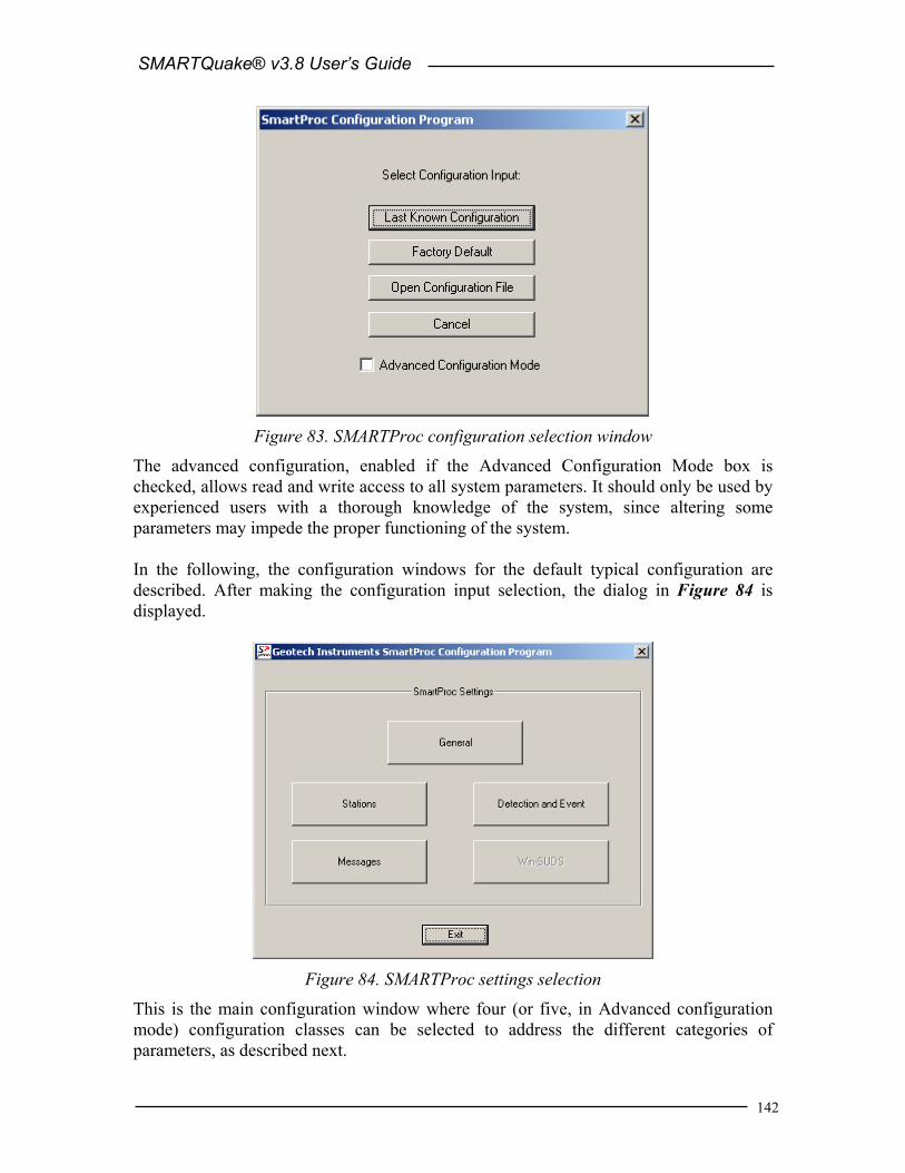
SMARTQuake® v3.8 User’s Guide
142
Figure 83. SMARTProc configuration selection window
The advanced configuration, enabled if the Advanced Configuration Mode box is checked, allows read and write access to all system parameters. It should only be used by experienced users with a thorough knowledge of the system, since altering some parameters may impede the proper functioning of the system. In the following, the configuration windows for the default typical configuration are described. After making the configuration input selection, the dialog in Figure 84 is displayed.
Figure 84. SMARTProc settings selection
This is the main configuration window where four (or five, in Advanced configuration mode) configuration classes can be selected to address the different categories of parameters, as described next.

SMARTQuake® v3.8 User’s Guide
143
Pressing the Exit button ends the system configuration process. A window like in Figure 85 is displayed, asking whether or not to save the SMARTProc settings.
Figure 85. SMARTProc save settings window
If the reply is ‘Save’, then the system configuration is updated and the parameters are copied to the control files of all the system modules. The new configuration information is saved in a file called C:\SMARTProc\SMARTProc.cfg, and a copy of the old configuration file is kept in C:\SMARTProc\SMARTProc1.cfg. If option ‘Save As’ is chosen, the settings are saved to a new configuration file; you are prompted to enter the desired file name and location. These settings do not become effective for SMARTProc, but any time later they can be read in and transported to the system using the SMARTProc Configure command. By this mechanism, the full system configuration can be performed in more that one session. If, on the other hand, the reply is ‘Don’t Save’, the configuration process is abandoned and no changes are made to the system configuration files.
14.4.1 General Settings When selecting the ‘General’ button in the main configuration window, the dialog shown in Figure 86 is displayed. The general system parameters settable by the user are: Data Files:
- Time interval to check for new raw data files SMARTProc looks for newly completed data files in its input folder and, if present, it creates a list of chronologically sorted input data files. If no newly completed files are found, it waits a certain time interval, as defined by this parameter (given in seconds), before repeating the check. The recommended value is 5 seconds.

SMARTQuake® v3.8 User’s Guide
144
Figure 86. SMARTProc General Settings window
- Time interval to wait for raw data file to be closed Before copying the newest completed file, SMARTProc waits this time interval (given in seconds) to make sure that the writing of the raw data file is completed. Recommended value is 1 second. If your data acquisition system, other than SMARTGeoHub® Data Server, is not keeping a temporary extension for the file being written until it is completed, this value has to be larger than the duration of one raw data file, typically by one second.
- Data acquisition mode: Continuous or Triggered Normal operation mode is Continuous, meaning that the data acquisition system (as for example SMARTGeoHub®) is producing continuous data files with constant time length. However, if your data acquisition system works in trigger-mode and produces event files, SMARTProc can be set up to work in Triggered mode as well, meaning that its internal event detection algorithm will be disabled and the triggered files transferred from the data acquisition system will enter directly in the event processing stage.
- Chronologically sort data files according to: Files date and time, SMART file names or IASPEI file names
It is essential for SMARTProc to process chronologically sorted data. The input files are ordered before being transferred to the processing directory, either according to the date and time when the file was last written to or to the file name information. The first option, ‘Files date and time’ is designed for on-line operation, when data are generated sequentially by a continuous file data acquisition system. The second choice accommodates also off-line operation,

SMARTQuake® v3.8 User’s Guide
145
when SMARTProc runs on a data set collected off-line, and there could be no relation between the data and files time stamps. This latter case depends on the files naming convention, and the options are: ‘SMART file names’ for handling files produced by the SMARTGeoHub® Data Server with the names described in §1.3 or ‘IASPEI file names’ for handling files generated by the XRTP program (IASPEI Shareware Software Library, Update of Volume 1) with names of form: YYMMDDZZ.ext, where YY = last 2-digit year, MM = month of year, DD = day of month, ZZ = a two-character combination of numbers (0 to 9) and letters (A to Z) and ext = the filename extension.
- Time length of the raw data files Duration of the raw data files, in seconds.
Warning: This parameter has to match the time length of the continuous files generated by the data acquisition system. - Use FDSN station naming convention
Check this box to use FDSN station name convention, meaning that three-component stations use the same station name for all three components. Uncheck this box when unique station/channel names are used and the first three characters uniquely identify the station for all three components, while the fourth character must be different, for example the component identifier ‘z’, ‘n’ or ‘e’.
Data Sources:
SMARTProc was designed to receive its stream of continuous data files from the data acquisition system, e.g. Geotech’s SMARTGeoHub® or Intelligent Communication Processor (ICP), in SUDS format. Other input data formats are supported if an appropriate file format converter (see below) or interface module is provided (see 11 Appendix 5). In most cases SMARTProc input data files are stored in a single acquisition directory (data source), as they are output by the data acquisition system. SMARTProc can also accept input data from multiple sources, like sub-networks of the same seismic network, provided they are produced by similar data acquisition systems: The raw files should have the same time length and follow the same naming convention, and possibly can have different data formats. If more than one data source is present, click on the Scan button to browse through data sources, on Add to add a new data source for SMARTProc and edit its configuration information, or on Delete to erase the current data source from SMARTProc configuration. For every data source following parameters can be defined: - Raw data files folder
This is the input data folder for SMARTProc, and also the output data folder for the data acquisition system.
- Raw data files extension All input data files are assumed to have this file extension (max. 4 characters). - Network name
When using the SMARTGeoHub® file naming convention (see §3.1), all input data files are assumed to have this network name (up to 7 characters). Leave this field blank if other naming conventions are used.

SMARTQuake® v3.8 User’s Guide
146
- Program/Command to convert raw data into demultiplexed SUDS format
SMARTProc uses demultiplexed SUDS version 1.51 as its internal data format and also as the default output format for the event files. If the input data are already in demultiplexed SUDS format, leave this parameter blank. If, on the other hand, the input data are in another format, enter here the name of the program used to convert them into demultiplexed SUDS version 1.51. In case the conversion program needs any command line arguments enter the complete command line including all arguments except for files names. SMARTProc will then invoke the program/command for every input data file, adding the corresponding input and output file names as arguments. The conversion program is assumed to reside in c:\smartproc. For example, if the input data have multiplexed SUDS format enter ‘demux’ and make sure that the Win-SUDS utility demux.exe is present in c:\smartproc.
Continuous Data Ring Buffer:
- Enable ring buffer Check this box to enable keeping the data files in SUDS format in a circular data buffer (recommended) when running in continuous data acquisition mode.
- Ring buffer folder This is the home folder for the data ring buffer, set at the time of installation to c:\dataring. This folder will host subdirectories corresponding to each of the calendar days present in the ring buffer and storing the data files recorded during that day. Each subdirectory name is given by the respective date, as follows. If the data files have long names, as those produced by SMARTGeoHub® Data Server (see §3.1), the first 8 characters of the file name are assumed to represent the date and give the name of the day subdirectory in which that data file is kept. If the files have short file names (8 characters only), then the first 6 characters give the date and the name of the day subdirectory. For example, the data file 20020804_062253_1.suds will be stored in the ring buffer directory c:\dataring\20020804, and the data file 020804ab.sud will be stored in the ring buffer directory c:\dataring\020804.
- Size of the ring buffer Enter the ring buffer storage capacity in Megabytes. Once the buffer size is reached, SMARTProc erases the data of the oldest day from the buffer. If two ring buffers are active, both are maintained using the same size limit.
When running both SMARTQuake® and SMARTProc it is recommended to enable the ring buffer option only in SMARTQuake®. Do not use same ring buffer folder on same computer for both applications!

SMARTQuake® v3.8 User’s Guide
147
SMARTGeoHub®:
- Enable automatic configuration from SMARTGeoHub®
Check this box to enable SMARTProc automatic configuration as received from Geotech’s SMARTGeoHub® Data Server. When SMARTProc is working integrated with the SMARTGeoHub®, and if this option is enabled, a subset of the parameters (common to both applications) are transported automatically from SMARTGeoHub® to SMARTProc, first time when starting the system and for every configuration change that takes place in the SMARTGeoHub® database. The automatically configurable parameters are the following: • Raw data files folder (for changes only) • Time length of the raw data files • Network name (for changes only) • Station name • Component name • Data channel status: active, meaning data is available for that
particular channel, or inactive, meaning no data but only configuration information is sent by the SMARTGeoHub® to SMARTProc
• Station Latitude • Station Longitude • Station Elevation • Sensor Sensitivity • Motion type (velocity or acceleration) • LSB • Sensor Type
SMARTProc reads the configuration messages received from SMARTGeoHub® and updates its configuration automatically starting with the first data file created after the new configuration becomes effective. If the reconfiguration involves changes in the data channels list (such as adding, removing or renaming data channels) SMARTProc will automatically perform a ‘New Start’.
- SMARTGeoHub® configuration file path If automatic configuration from SMARTGeoHub® is enabled, use this field to set the path (local or across the network) of the configuration messages generated by SMARTGeoHub®.
When running both SMARTQuake® and SMARTProc integrated with the SMARTGeoHub®, disable the automatic configuration option for SMARTProc and enable it for SMARTQuake® only.

SMARTQuake® v3.8 User’s Guide
148
For information only, the name of the SMARTProc home directory as set at the time of the installation is displayed in the window’s lower right corner. After changing/reviewing all parameters, click OK to keep the newly entered values or click Cancel to keep the default values and ignore parameter changes done in this configuration window. Next, the main configuration window is displayed with the option to select another configuration window or to exit the configuration process.
14.4.2 Station Settings When selecting the ‘Stations’ button in the main configuration window, the current list of stations is shown. Stations can be configured, added to or removed from the list as described below (Figure 87).
Figure 87. SMARTProc Station List window
To configure a station in the list, select it with the mouse and click on the Edit button. By default, the first station is selected. The next window is displayed (Figure 88), allowing setting up parameters of the selected station and all its components. To add a new station to the list, just click on the Add button. Another window (as shown in Figure 88) is opened to allow entering the new station parameters, starting from default values given by the configuration of the last selected station or, by default, of the first station in the list. Change the default values as needed, starting with the station name. Press Cancel to abandon adding the new station, or any other button to save it. To delete a station from the list, select it with the mouse and click on the Delete button. Confirmation will be required before removing the station from the list.

SMARTQuake® v3.8 User’s Guide
149
Figure 88. SMARTProc Station Settings window
Station:
- Station name The name of the station, up to five characters (left justified); it should exactly match to the name in the data logger. For three-component stations, it is recommended to use the same station name for all three components (FDSN station name convention). However, this is not possible when input data are in the old 16-bit SUDS format without support for long station/component identifiers (version older than 1.51), and unique station/channel names (up to four characters) are required. In this case, enter in this field the channel name and make sure that its first three characters uniquely identify the station for all three components, while the fourth character must be different, for example the component identifier ‘z’, ‘n’ or ‘e’. Also, disable the use of FDSN station name convention under General Settings (see §14.4.1).
Site information:
Site parameters are associated with the station; they are the following: - Latitude
Station geographic latitude in degrees. Check the box below if the site is in the southern hemisphere.
- Longitude

SMARTQuake® v3.8 User’s Guide
150
Station geographic longitude in degrees. Check the box below if the site is in the western hemisphere.
- Elevation Station elevation in meters.
Component:
- Component name Any station component can be selected from the ‘component name’ list box. The component descriptor is up to three characters (left justified) and should exactly match to the name in the data logger. For vertical components, include the character ‘v’ or ‘z’ (uppercase or lowercase) in the component name. Also, for horizontal components oriented on the North-South or East-West direction, include the character ‘n’ or ‘e’ (uppercase or lowercase), respectively, in the component name. When input data are in the old 16-bit SUDS format without support for long station/component identifiers (version earlier than 1.51), the component descriptor has one single character. To change a component’s name, select it from the list and click Edit. A dialog window opens to allow editing the name. Press OK to keep the new component name or Cancel to keep the default. To add a new component, click on the Add button. A dialog window is displayed to allow entering the component name. Change the default component name (‘NEW’) and press OK to accept it. To delete an existing component, select it with the mouse and click on the Delete button. Confirmation will be required before removing the component.
Following parameters are associated with the component, and can be changed independently for every station’s component (data channel):
Instrument Parameters:
Instrument parameters are used by SMARTProc to apply instrument correction for ground motion acceleration determination. - Sensor Sensitivity
Sensitivity for this sensor in Volts/(meters/sec2) (floating point value). Check the box below if the sensor is an accelerometer; otherwise a velocity sensor is assumed. For velocity data channels the instrument parameters are displayed for information only, as velocity data channels are not processed by SMARTProc.
- LSB Digitizer LSB, corrected by any gain applied, in µVolts/digital counts (floating point value).
- Sensor Name Name of the sensor (maximum 6 characters); e.g., PA-23 for the Geotech’s acceleration sensor model PA-23.
Processing Options:
- Exclude for detection only

SMARTQuake® v3.8 User’s Guide
151
Check this box to declare the channel inactive for event detection only. - Exclude for detection and PGA reporting
Check this box to declare the channel inactive for both event detection and PGA reporting.
After changing/reviewing all station parameters, click OK to keep the newly entered values or click Cancel to keep the default values. In either case the station list window is displayed next, with the option to select another station to be configured or to close station configuration and return to the main configuration window. Or, you may click on Next to keep the newly entered values and go to the next station in the list, or on Back to keep the newly entered values and go to the previous station in the list.
14.4.3 Detection and Event Settings
When selecting the ‘Detection and Event’ button in the main configuration window, the next window is displayed (Figure 89).
Detection: - PGA detection threshold in cm/sec2
Enter the PGA detection threshold (given in cm/sec2). For every station the maximum PGA value on any component is used.
- Time window for event detection Enter the event detection window in seconds. Same detection scheme as defined for SMARTQuake® is used (see §1.3).
- Minimum number of triggers in window for event detection Enter the minimum number of triggered stations for declaring an event, as defined in §1.3. Enter ‘0’ to disable SMARTProc event detection and processing, and keep ring buffer functionality only.
Filter Cut-off: - Low and High frequency limits
Bandpass filter cut-off frequencies in Hertz. The filter is a 4-pole Butterworth band-pass filter applied in the time domain in the forward direction. Enter ‘0’ for the low or high frequency values to apply only high-pass or only low-pass filtering. SMARTProc uses these parameters for filtering the data before sending them to the event detector.

SMARTQuake® v3.8 User’s Guide
152
Figure 89. SMARTProc Detection and Event Settings window
Event: - Minimum pre-event time
Based on this value (given in seconds) SMARTProc determines how many input data files to consider as pre-event time for event file formation (see §1.3).
- Output file extension Waveform event files in SUDS format and the files stored in the ring buffer have this extension.
- Enable on-screen display of waveforms Check this box to enable displaying the event waveforms on the screen. Event waveforms are displayed only for a short time interval (10 seconds) while the event is still being processed. If this option disabled, SMARTProc runs as a background application and no plots are displayed (but sent to the printer).
Printing and Emails: - Printer port, local or network:
Enter the name of the local port (e.g. lpt1) or network port (e.g. \\server\printer) where a PostScript compatible printer is connected to, or leave this field blank to disable printouts.
- SMARTProc operator email address and SMTP mail server First name in this field is the email address of the system operator (e.g. [email protected]). This is the destination address for sending the ‘state-of-health’ messages, periodically and at every system start or stop. Also it is the sender address for the emails with location results produced by SMARTProc. The name of the SMTP mail server used for automatic email sending can be entered after the operator email address, separated by a comma. If only the operator email address is entered, the SMTP mail server name is read from the

SMARTQuake® v3.8 User’s Guide
153
first part of the domain name in the operator email address (in the example above, the SMTP mail server is server). To disable email sending, leave this field blank.
- Sender name for outgoing emails This parameter is used as sender name for automatic emails, and usually is an identification string for the agency or network.
- Subject of outgoing emails Automatic emails sent by SMARTProc have this subject line. After changing/reviewing all parameters, click OK to keep the newly entered values or click Cancel to keep the default values and ignore parameter changes done in this configuration window. Next the main configuration window is displayed with the option to select another configuration window or to exit the configuration process.
14.4.4 Messaging Settings When selecting the ‘Messages’ button in the main configuration window, the following window is displayed (Figure 90). It allows setting up the list of addresses and telephone numbers that SMARTProc uses for sending emails and SMS messages with SMARTProc results. By default (factory settings), these lists are empty. They can be changed following the same procedure as for SMARTQuake®, described in §3.2.8.
Figure 90. SMARTProc Messaging Settings window
SMARTProc emails messages contain the SMARTProc results, as shown in the example in Figure 91.

SMARTQuake® v3.8 User’s Guide
154
STAT COMP LATITUDE LONGITUDE PGA(cm/s2) DATE TIME ===================================================================== VR1Z V 45.86567 26.72767 .4404 20040121 054929.215 VR1E E 45.86567 26.72767 .3604 20040121 054942.700 VR1N N 45.86567 26.72767 .2346 20040121 054943.610 SE1E E 45.03550 26.06767 3.7959 20040121 054945.185 SE1N N 45.03550 26.06767 3.4929 20040121 054945.295 SE1Z V 45.03550 26.06767 2.0381 20040121 054945.595 STAT COMP LATITUDE LONGITUDE PGV(cm/s) DATE TIME ===================================================================== VR1Z V 45.86567 26.72767 .0064 20040121 054929.540 VR1E E 45.86567 26.72767 .0134 20040121 054942.765 VR1N N 45.86567 26.72767 .0097 20040121 054943.535 SE1E E 45.03550 26.06767 .1252 20040121 054945.215 SE1N N 45.03550 26.06767 .1472 20040121 054945.370 SE1Z V 45.03550 26.06767 .0497 20040121 054946.275 STAT COMP LATITUDE LONGITUDE PGD(cm) DATE TIME ===================================================================== VR1Z V 45.86567 26.72767 .0023 20040121 054943.370 SE1E E 45.03550 26.06767 .0052 20040121 054945.265 SE1N N 45.03550 26.06767 .0090 20040121 054945.440 SE1Z V 45.03550 26.06767 .0024 20040121 054949.645 VR1E E 45.86567 26.72767 .0023 20040121 055019.925 VR1N N 45.86567 26.72767 .0015 20040121 055030.915
Figure 91. Example of SMARTProc email message
SMARTProc SMS text messages contain very brief information on the detected event, that includes the date and time, maximum PGA value recorded over all stations, and the station name and position where the maximum ground shaking was recorded, as shown in the example in Figure 92.
Subject: Automatic SMARTProc Detection: 2004/01/21 05:49:45 PGA= 93.8cm/s2 SE1E LAT: 45.035 LON: 26.068
Figure 92. Example of SMARTProc SMS text message
After being configured as described above, SMARTProc is now ready to run (see §14.5).
14.5 SMARTProc Operation To run SMARTProc, double click on the SMARTProc icon from the Desktop. The string motion automated processor GUI will be displayed as shown in Figure 93. The Messages window provides information on system functioning and event detections: the date and time when different operations are performed (as for example configuring or starting/stopping data processing), and for every detected event the maximum PGA recorded, corresponding station name, and date and time. The first menu, Commands, allows commanding system actions, while the second menu, Settings, gives access to the system configuration tools.

SMARTQuake® v3.8 User’s Guide
155
14.5.1 Commands The Commands menu has the following options:
Figure 93. SMARTProc Messages window
- Start This is the command to start the SMARTProc processor, preserving continuity in system activities. Whenever the flow of data processing is temporarily interrupted, by stopping the processor using the ‘Stop’ command, it can be resumed, without any discontinuity in event detection and processing, by selecting ‘Start’. SMARTProc will start by analyzing first the oldest unprocessed data files.
- New Start
This is the command necessary to be used when starting the SMARTProc processor for the first time, or after manually reconfiguring SMARTProc and any data channels were added, removed or renamed.
Whenever SMARTGeoHub® Data Server is reconfigured involving such changes in the data channels list, SMARTProc will automatically stop operation, reconfigure it self, and then perform a ‘New Start’. Therefore, in this case it is not necessary for the system operator to issue the ‘New Start’ command manually.

SMARTQuake® v3.8 User’s Guide
156
This command performs the complete reset of the data processor activities. It interrupts the continuity of event detection and causes a detection inactivity period of at least two times the time length of one input data file. All temporary files that insure continuity in event detection are deleted.
- Stop
This is the command to temporarily stop the automated processor. If one event has just been detected, the interruption is done only after completing all processing steps for that event file (usually only several seconds). To resume the processing activity, one can use one of the commands ‘Start’ (which assures continuity in processing) or ‘New Start’ (which performs a full reset of the processor). After issuing the ‘Stop’ command, wait a few seconds, as instructed on the Messages window, for the completion of the system shutdown. A message box will inform when the system has actually stopped operation.
- Delete Ring Buffer
This command deletes the entire content of the ring data buffer. The user is prompted for confirmation before deleting the ring buffer.
- Move Ring Buffer
This command moves the entire content of the ring data buffer to the SMARTProc input data folder. Subsequently, the entire data set can be processed by issuing the ‘New Start’ command. This option is in particular useful to allow re-runs of SMARTProc processing (in off-line mode) on same data set using different processing parameters. The user is prompted for confirmation before moving the ring buffer.
- View Log
A history of all messages displayed in the SMARTProc message window, logging system main activities like system start, stop, configuration, ring buffer clean-up or event detections, can be viewed by using this command. It is enabled only when the processor is stopped.
- Exit
This is the command to exit and close all SMARTProc windows. It is enabled only when the processor is stopped.
14.5.2 Settings The Settings menu has the following options (Figure 94):

SMARTQuake® v3.8 User’s Guide
157
Figure 94. SMARTProc Settings menu
- Configure This is the command to start SMARTProc configuration. It is necessary to run this command before starting SMARTProc for the first time and whenever the automated processor parameters need to be changed. Before running ‘Configure’, the ‘Stop’ command has to be used for stopping the processor. For a detailed description of the configuring process, see §14.4.
Whenever SMARTGeoHub® Data Server is reconfigured, SMARTProc will stop operation, reconfigure it self automatically, and then it will restart processing (by performing a ‘Start’ or a ‘New Start’, depending on what parameters have been changed). Therefore, in such cases it is not necessary for the system operator to issue the ‘Configure’ command manually.
- Regenerate Parameter Files
This is the command to regenerate all SMARTProc parameter files, based on the last saved configuration information. This command can be used if one of the SMARTProc parameter files was accidentally deleted and it needs to be recreated, and there is no need to perform any configuration changes. By executing it, the configuration information currently stored in the file SMARTProc.cfg will be copied to the control files of all the system modules.

SMARTQuake® v3.8 User’s Guide
158
14.5.3 Running SMARTProc When SMARTProc is in operation, its main program, the SMARTProcManager runs continuously in the background as the ‘processing manager’. It controls execution of all system tasks: data transfer from the acquisition program, check for detection, event processing, and state of health reports. Make sure not to accidentally close the SMARTProcManager window running minimized (on the Windows taskbar). Only the commands previously described (in §14.5.1) to stop or start the processor should be used. While the automated processor is running as a background application, in case of event detection system messages reporting the event date and time, and maximum recorded PGA value are displayed in the SMARTProc Messages window (Figure 95). Only when the ‘on-screen display of processing results’ option is enabled, the event waveforms are shown on the screen following event detection, as shown in Figure 96.
Figure 95. SMARTProc event detection

SMARTQuake® v3.8 User’s Guide
159
Figure 96. SMARTProc event waveforms plot
SMARTProc is a fully automated task and does not require special maintenance procedures to be performed by the system operator. The archive directory (containing all processing results) can be accessed locally or across the network for operations as backup and clean-up, according to the specific hardware and software system configuration. Logging information A log of all system messages as shown in the Messages window is kept in the file c:\smartproc\smartproc.log. Also, a log of failed or cancelled emails is stored in the file c:\smartproc\maillog.

SMARTQuake® v3.8 User’s Guide
160
(Page Intentionally Left Blank)