Embed Size (px)
Citation preview
SmartPTT Enterprise
User Guide
Version 8.1
smartptt.com
Table of Contents
..........................................................................................................................................71 Introduction
..........................................................................................................................................92 SmartPTT Dispatcher
..................................................................................................................... 92.1 Main Features
..................................................................................................................... 102.2 SmartPTT Dispatcher Interface
..................................................................................................................... 122.3 Subscriber Management Panel
..................................................................................................................... 262.4 Operators
..................................................................................................................... 282.5 Map
..................................................................................................................... 392.6 Event Log
..................................................................................................................... 472.7 View
............................................................................................................482.7.1 Sound Panel
............................................................................................................502.7.2 Call History
............................................................................................................512.7.3 Subscribers
............................................................................................................522.7.4 Points of Interest
............................................................................................................532.7.5 Subscriber Location Panel
............................................................................................................542.7.6 Control Zone Panel
............................................................................................................552.7.7 Routes
............................................................................................................592.7.8 Lone Workers
............................................................................................................602.7.9 Server Tasks
............................................................................................................602.7.10 Monitoring
............................................................................................................772.7.11 System Messages
............................................................................................................782.7.12 Notifications
............................................................................................................792.7.13 Job Tickets
..................................................................................................................... 822.8 Settings
............................................................................................................832.8.1 Database
............................................................................................................852.8.2 Licenses
............................................................................................................872.8.3 General Settings
............................................................................................................892.8.4 Radioservers
............................................................................................................932.8.5 Statuses
............................................................................................................952.8.6 Event Log
............................................................................................................962.8.7 Call Windows
............................................................................................................972.8.8 Sound
............................................................................................................1002.8.9 Record
............................................................................................................1012.8.10 GPS
............................................................................................................1022.8.11 Raster Map
............................................................................................................1042.8.12 Telemetry
............................................................................................................1082.8.13 Categories
............................................................................................................1122.8.14 Dispatchers
............................................................................................................1162.8.15 Telephone Settings
............................................................................................................1292.8.16 Job Ticket Statuses
............................................................................................................1312.8.17 Third-Party Equipment
............................................................................................................1362.8.18 Hot Keys
............................................................................................................1402.8.19 Rules and Alerts
............................................................................................................1472.8.20 GPS Rules
............................................................................................................1532.8.21 Lone Worker Rules
............................................................................................................1592.8.22 Subscriber Custom Properties
............................................................................................................1632.8.23 Custom Consoles
..................................................................................................................... 1732.9 Service
............................................................................................................1742.9.1 Radio Check
............................................................................................................1752.9.2 SmartPTT Database
smartptt.com
............................................................................................................1772.9.3 Export Radio Subscribers
............................................................................................................1782.9.4 Import Radio Subscribers
............................................................................................................1802.9.5 Upload to KML
............................................................................................................1822.9.6 Import Connect Plus Logs
............................................................................................................1832.9.7 View Received Files
............................................................................................................1842.9.8 View Deferred Actions
............................................................................................................1872.9.9 Voice Notifications
............................................................................................................1892.9.10 View System Information
..................................................................................................................... 1902.10 Reports
............................................................................................................1912.10.1 Report Wizard
............................................................................................................1942.10.2 Radio Activity Report
............................................................................................................1962.10.3 Subscriber Location Report
............................................................................................................1972.10.4 Online Subscribers
............................................................................................................1982.10.5 Monitoring Report
............................................................................................................2002.10.6 Monitoring Analysis
..................................................................................................................... 2012.11 Help
..................................................................................................................... 2022.12 Bridging
..................................................................................................................... 2042.13 Conference Calls
..................................................................................................................... 2082.14 Window Configuration
..................................................................................................................... 2092.15 Panel Positioning
..................................................................................................................... 2112.16 Remote Assistance
..........................................................................................................................................2143 SmartPTT Radioserver Configurator
..................................................................................................................... 2143.1 Main Features
..................................................................................................................... 2153.2 Radioserver
............................................................................................................2173.2.1 Services
.............................................................................................2173.2.1.1 ARS
.............................................................................................2183.2.1.2 Location
.............................................................................................2203.2.1.3 TMS
.............................................................................................2203.2.1.4 Telemetry
.............................................................................................2203.2.1.5 Email Gateway
.............................................................................................2283.2.1.6 SMS Gateway
.............................................................................................2353.2.1.7 Subscriber Blacklist
.............................................................................................2383.2.1.8 DDMS
.............................................................................................2383.2.1.9 MNIS
.............................................................................................2403.2.1.10 File Receive
............................................................................................................2453.2.2 Add-on Modules
.............................................................................................2453.2.2.1 Licenses
.............................................................................................2463.2.2.2 Event Log
Settings ..............................................................................................246
.............................................................................................2493.2.2.3 Telephone Interconnect
.............................................................................................2563.2.2.4 Bridging
.............................................................................................2573.2.2.5 Web Client Support
.............................................................................................2573.2.2.6 Voice Notifications
.............................................................................................2593.2.2.7 SNMP Service
.............................................................................................2603.2.2.8 Monitoring
............................................................................................................2623.2.3 Control Station
.............................................................................................2663.2.3.1 How to Configure Control Station Channels
.............................................................................................2673.2.3.2 How to Configure Control Station Groups
.............................................................................................2683.2.3.3 How to Configure Control Station Audio Settings
............................................................................................................2693.2.4 IP Site Connect
.............................................................................................2693.2.4.1 How to Configure IP Site Connect
How to Configure IP Site Connect Slots..............................................................................................269
smartptt.com
..............................................................................................269..............................................................................................269..............................................................................................269..............................................................................................269How to Configure Groups for IP Site Connect Slots
............................................................................................................2743.2.5 Capacity Plus
.............................................................................................2753.2.5.1 How to Configure Capacity Plus
How to Configure Virtual Control Station..............................................................................................275
..............................................................................................275..............................................................................................275..............................................................................................275..............................................................................................275How to Configure Groups
How to Configure TX Control Station..............................................................................................275
..............................................................................................275..............................................................................................275..............................................................................................275..............................................................................................275How to Configure Groups and Channels of TX Control Station
..............................................................................................275..............................................................................................275..............................................................................................275..............................................................................................275Audio Settings
............................................................................................................2823.2.6 Connect Plus
.............................................................................................2833.2.6.1 How to Configure Connect Plus
How to Configure Connect Plus Groups..............................................................................................283
............................................................................................................2853.2.7 Radio Activity
.............................................................................................2853.2.7.1 How to Configure Radio Activity DMR Network
How to Configure Radio Activity DMR Slots..............................................................................................285
..............................................................................................285..............................................................................................285..............................................................................................285..............................................................................................285How to Configure Radio Activity DMR Slot Groups
............................................................................................................2883.2.8 Connect Plus Monitoring
.............................................................................................2903.2.8.1 How to Configure Connect Plus Networks Monitoring
How to Configure Connect Plus Monitoring Virtual Control Station..............................................................................................290
..............................................................................................290..............................................................................................290..............................................................................................290..............................................................................................290How to Configure Groups
............................................................................................................2933.2.9 MNAI
.............................................................................................2953.2.9.1 How to Configure MNAI
How to Configure MNAI Slots..............................................................................................295
..............................................................................................295..............................................................................................295..............................................................................................295..............................................................................................295How to Configure MNAI Groups
MNIS and DDMS service settings..............................................................................................295
............................................................................................................3053.2.10 SmartPTT Radioservers
..................................................................................................................... 3223.3 Profiles
..................................................................................................................... 3243.4 Subscriber Groups
..................................................................................................................... 3253.5 Multigroups
..................................................................................................................... 3263.6 Rules
..................................................................................................................... 3293.7 Monitoring
..................................................................................................................... 3303.8 Client List
..................................................................................................................... 3303.9 Network Configuration
..................................................................................................................... 3363.10 Log
..................................................................................................................... 3373.11 Export/Import Settings
..................................................................................................................... 3383.12 Statistics
..........................................................................................................................................3404 Troubleshooting
7
smartptt.com
Introduction
1 Introduction
SmartPTT is a software package designed to manage dispatch communication between linear-extended
and geographically-distributed objects where it is necessary to facilitate voice and data transmission
between remote control stations of the radio network.
SmartPTT implements all benefits of the MOTOTRBO digital platform.
SmartPTT architecture manages subscriber networks of any size and topology, using both digital
functions of MOTOTRBO radio stations and analog mode to facilitate a gradual upgrade to the new radio
communication standard. It is also possible to use a "mixed" mode when some sites operate in the
analog mode and others in the digital mode.
SmartPTT architecture consists of three segments:
Management segment (dispatcher network administrators)
Base segment (Includes radioservers connected to stationary radios (mobile MOTOTRBO stationsas control stations) and repeaters.)
User segment (the entire fleet of subscribers (mobile and portable radios)
The management segment implements control and monitoring functions – data management (telemetry,
telemechanics), human resources management and industrial process control – via access to the base
segment. The dispatcher has either full or partial access to the system radioserver, that is a software
installed on PCs. SmartPTT software enables various MOTOTRBO platform functions, which form the
basis of the system.
Radioservers are linked to fixed stations, which are control stations for the system (up to 4 per
radioserver), and repeaters (IP-enabled, up to 14 per radioserver). All repeaters are interconnected via IP
network and enable subscriber roaming and formation of a common, geographically distributed
communication network. Communication zones can be both adjacent and separated. The number of
radioserver and dispatcher seats is unlimited.
The radioserver database stores radio station pool data. When the MOTOTRBO subscriber digital radio
station enters the SmartPTT network coverage zone, it sends a request to the radioserver and, in the
event of successful authentication, it is registered automatically.
8
smartptt.com
Introduction
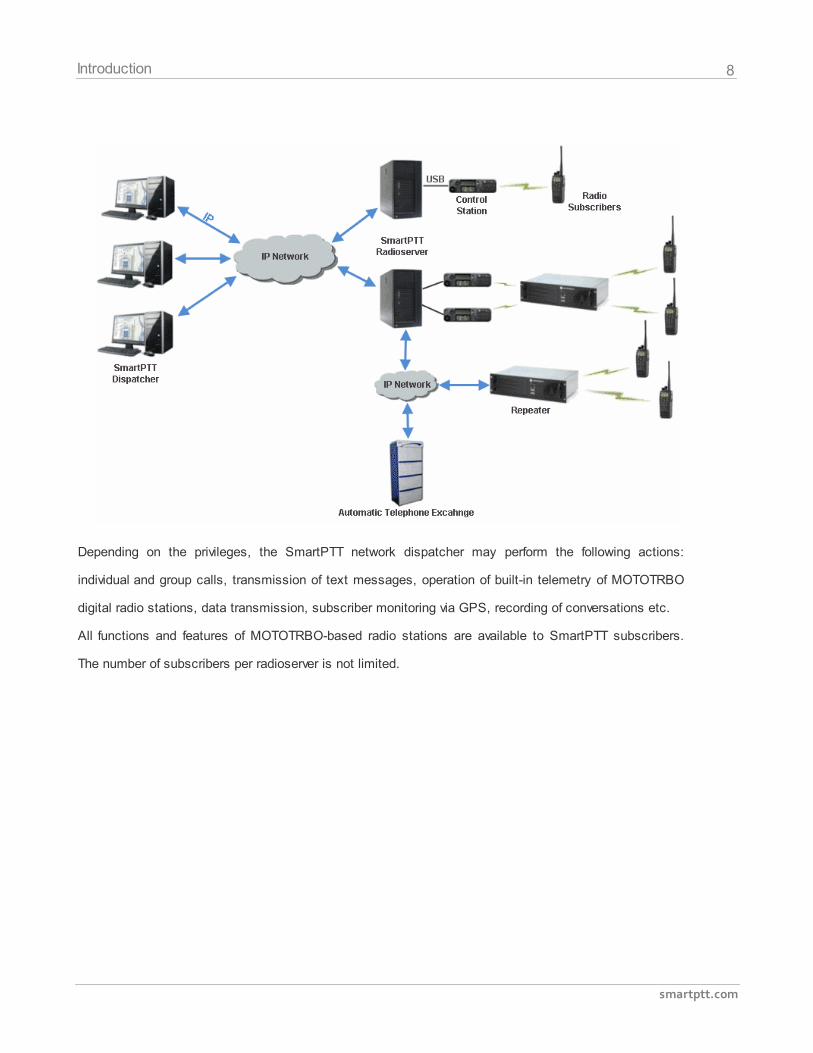
Depending on the privileges, the SmartPTT network dispatcher may perform the following actions:
individual and group calls, transmission of text messages, operation of built-in telemetry of MOTOTRBO
digital radio stations, data transmission, subscriber monitoring via GPS, recording of conversations etc.
All functions and features of MOTOTRBO-based radio stations are available to SmartPTT subscribers.
The number of subscribers per radioserver is not limited.
9
smartptt.com
Introduction
2 SmartPTT Dispatcher
2.1 Main Features
SmartPTT includes a number of functions. Each function provides complete functionality and is designed
for a specific task.
Here is a brief list of the main functions SmartPTT software has to offer:
1. Dispatcher voice communication. SmartPTT Dispatcher supports 4 subscriber types for
dispatcher communication:
MOTOTRBO radios
Analog radios
Telephone subscriber
Other SmartPTT Dispatcher consoles
2. Voice call recording. All voice calls, even private ones between subscribers, can be recorded in
MP3 files and stored both on the radioserver and on the client side.
3. Subscriber location tracking (AVL). Real-time GPS-based fleet management system provides
constant tracking of subscriber location, keeps the log of the tracks, controls subscriber
movement via configured set of rules on several types of maps.
4. Integration with telephone networks via VoIP. SmartPTT Dispatcher implements Telephone
Interconnect Gateway to make calls between MOTOTRBO or analog radios and telephone
subscribers. A phone call can be initiated by a radio subscriber, a dispatcher or a telephone
subscriber.
5. Radio network bridging. SmartPTT Routing Service allows call patching between multiple radio
networks of the same or different types type (IP Site Connect, Capacity Plus, digital conventional,
and analog conventional networks), as well as between multiple SmartPTT Radioservers. Unique
dynamic intelligent routing of private and group calls is based on the information about the
subscriber registration in the network.
6. Text and data transfer. SmartPTT Dispatcher allows exchanging text messages between radio
10
smartptt.com
SmartPTT Dispatcher
subscribers, supports subscriber statuses, native MOTOTRBO telemetry features. Gateways to
E-mail and GSM provides opportunity for MOTOTRBO subscribers to exchange text messages
with e-mail boxes and mobile cellphones correspondingly.
7. Real-time network monitoring. SmartPTT provides graphical representation of MOTOTRBO
infrastructure, information about type of data transferred by repeaters, hardware failures logging,
coverage map drawing, and more.
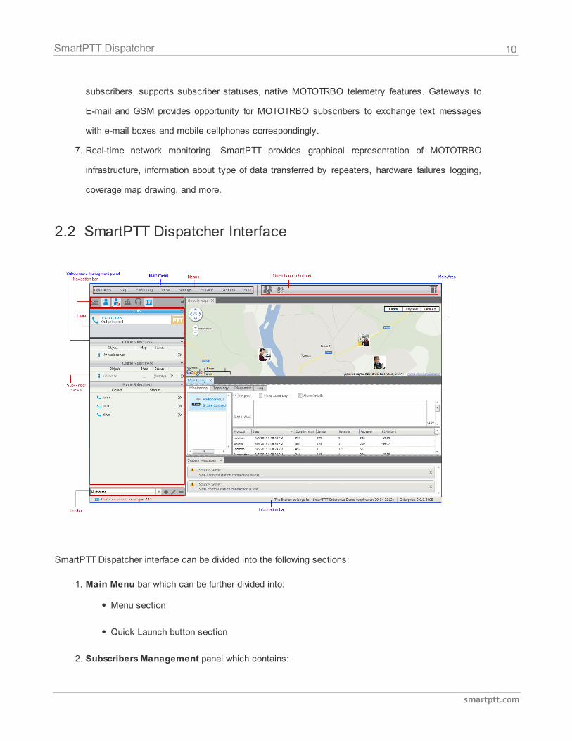
2.2 SmartPTT Dispatcher Interface
SmartPTT Dispatcher interface can be divided into the following sections:
1. Main Menu bar which can be further divided into:
Menu section
Quick Launch button section
2. Subscribers Management panel which contains:
11
smartptt.com
SmartPTT Dispatcher
Navigation bar
Calls section
Subscriber panels
Toolbar
3. Main area
4. Information bar
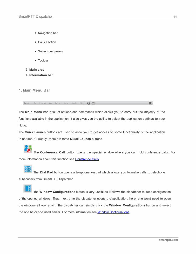
1. Main Menu Bar
The Main Menu bar is full of options and commands which allows you to carry out the majority of the
functions available in the application. It also gives you the ability to adjust the application settings to your
liking.
The Quick Launch buttons are used to allow you to get access to some functionality of the application
in no time. Currently, there are three Quick Launch buttons.
The Conference Call button opens the special window where you can hold conference calls. For
more information about this function see Conference Calls.
The Dial Pad button opens a telephone keypad which allows you to make calls to telephone
subscribers from SmartPTT Dispatcher.
The Window Configurations button is very useful as it allows the dispatcher to keep configuration
of the opened windows. Thus, next time the dispatcher opens the application, he or she won't need to open
the windows all over again. The dispatcher can simply click the Window Configurations button and select
the one he or she used earlier. For more information see Window Configurations.
12
smartptt.com
SmartPTT Dispatcher
3. Main Area
The Main area is a central area of the application window and is used for opening functional windows
and panels when operating in the application.
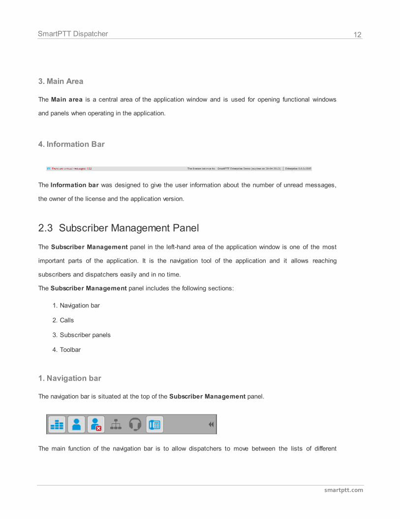
4. Information Bar
The Information bar was designed to give the user information about the number of unread messages,
the owner of the license and the application version.
2.3 Subscriber Management Panel
The Subscriber Management panel in the left-hand area of the application window is one of the most
important parts of the application. It is the navigation tool of the application and it allows reaching
subscribers and dispatchers easily and in no time.
The Subscriber Management panel includes the following sections:
1. Navigation bar
2. Calls
3. Subscriber panels
4. Toolbar
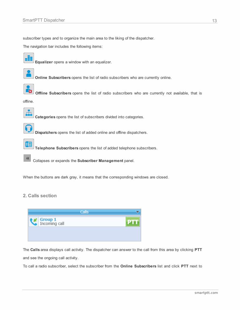
1. Navigation bar
The navigation bar is situated at the top of the Subscriber Management panel.
The main function of the navigation bar is to allow dispatchers to move between the lists of different
13
smartptt.com
SmartPTT Dispatcher
subscriber types and to organize the main area to the liking of the dispatcher.
The navigation bar includes the following items:
Equalizer opens a window with an equalizer.
Online Subscribers opens the list of radio subscribers who are currently online.
Offline Subscribers opens the list of radio subscribers who are currently not available, that is
offline.
Categories opens the list of subscribers divided into categories.
Dispatchers opens the list of added online and offline dispatchers.
Telephone Subscribers opens the list of added telephone subscribers.
Collapses or expands the Subscriber Management panel.
When the buttons are dark gray, it means that the corresponding windows are closed.
2. Calls section
The Calls area displays call activity. The dispatcher can answer to the call from this area by clicking PTT
and see the ongoing call activity.
To call a radio subscriber, select the subscriber from the Online Subscribers list and click PTT next to
14
smartptt.com
SmartPTT Dispatcher
the subscriber name or press the Space key. PTT becomes yellow. When the subscriber responds, PTT
turns green. To end communication, click PTT or the Space key once more.
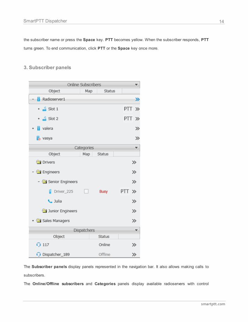
3. Subscriber panels
The Subscriber panels display panels represented in the navigation bar. It also allows making calls to
subscribers.
The Online/Offline subscribers and Categories panels display available radioservers with control
15
smartptt.com
SmartPTT Dispatcher
stations, groups and radio subscribers. The sections include the following columns:
1. Object
2. Map
3. Status
4. PTT
5. Action List
The Object field shows the subscriber or radioserver name.
Note: For easier search of the subscribers in the list, use searching by name. To do it, place the mouse
cursor in any of the subscriber panels on the left and type his or her name used in the system. At that, if
any match of letters occurs, the system focuses on the subscriber.
The Map check box turns on/off the display of the subscriber location on the map (applicable to radio
subscribers only).
The Status field displays the status of the subscribers or dispatchers.
PTT initiates a call.
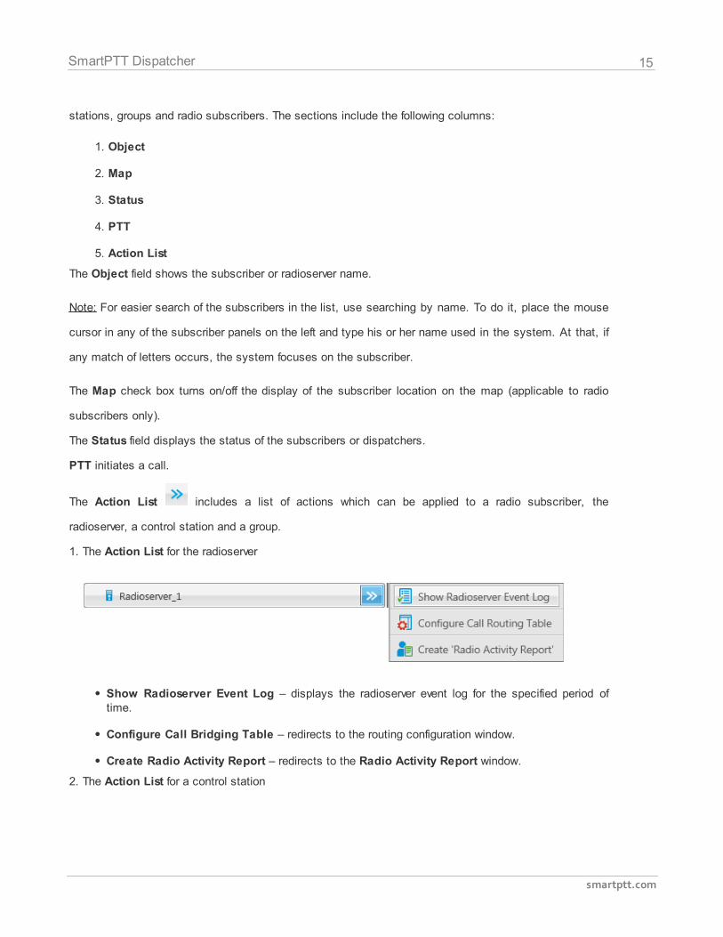
The Action List includes a list of actions which can be applied to a radio subscriber, the
radioserver, a control station and a group.
1. The Action List for the radioserver
Show Radioserver Event Log – displays the radioserver event log for the specified period oftime.
Configure Call Bridging Table – redirects to the routing configuration window.
Create Radio Activity Report – redirects to the Radio Activity Report window.
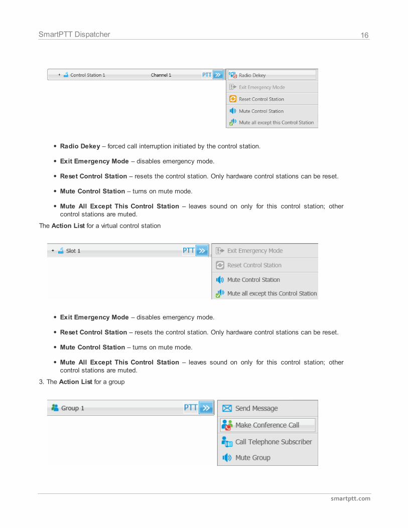
2. The Action List for a control station
16
smartptt.com
SmartPTT Dispatcher
Radio Dekey – forced call interruption initiated by the control station.
Exit Emergency Mode – disables emergency mode.
Reset Control Station – resets the control station. Only hardware control stations can be reset.
Mute Control Station – turns on mute mode.
Mute All Except This Control Station – leaves sound on only for this control station; othercontrol stations are muted.
The Action List for a virtual control station
Exit Emergency Mode – disables emergency mode.
Reset Control Station – resets the control station. Only hardware control stations can be reset.
Mute Control Station – turns on mute mode.
Mute All Except This Control Station – leaves sound on only for this control station; othercontrol stations are muted.
3. The Action List for a group
17
smartptt.com
SmartPTT Dispatcher
Send Message – opens a window for creating and sending messages.
Make Conference Call – opens the Conference Call window and starts the conference call.
Call Telephone Subscriber – opens the window with the list of registered telephone subscribersand Dial.
Mute Group – turns on mute mode for this group.
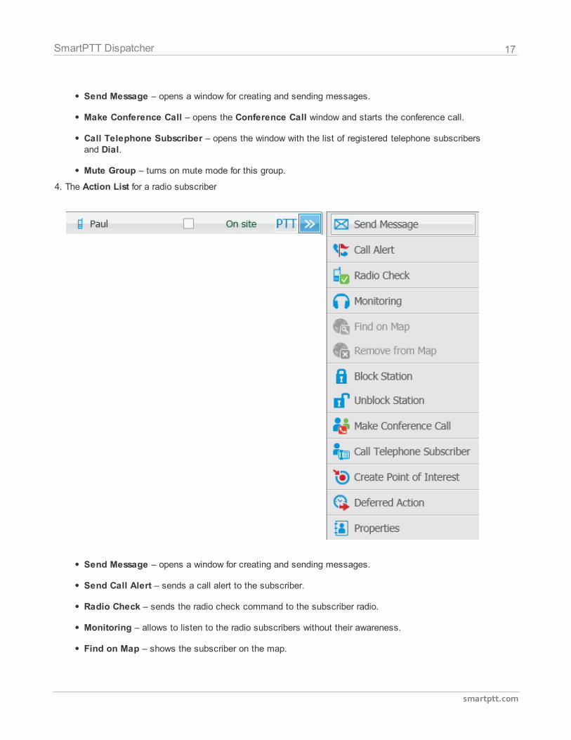
4. The Action List for a radio subscriber
Send Message – opens a window for creating and sending messages.
Send Call Alert – sends a call alert to the subscriber.
Radio Check – sends the radio check command to the subscriber radio.
Monitoring – allows to listen to the radio subscribers without their awareness.
Find on Map – shows the subscriber on the map.
18
smartptt.com
SmartPTT Dispatcher
Remove from Map – removes from the map.
Block Radio – sends the Block Radio command to the subscriber radio.
Unblock Radio – sends the Unlock Radio command to the subscriber radio.
Make Conference Call – opens the Conference Call window and starts the conference call.
Call Telephone Subscriber – opens the window with the list of registered telephone subscribersand the Dial button.
Create Point of Interest – create POI at the current place of the subscriber. If there are nocoordinates, the system uses the latest coordinates received from the radio. If coordinates areabsent altogether, nothing happens.
Create Deferred Action – opens a window for creation of the deferred action.
View Properties – opens the subscriber's Properties window.
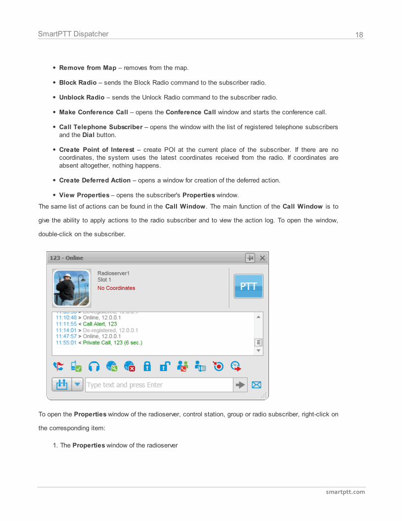
The same list of actions can be found in the Call Window. The main function of the Call Window is to
give the ability to apply actions to the radio subscriber and to view the action log. To open the window,
double-click on the subscriber.
To open the Properties window of the radioserver, control station, group or radio subscriber, right-click on
the corresponding item:
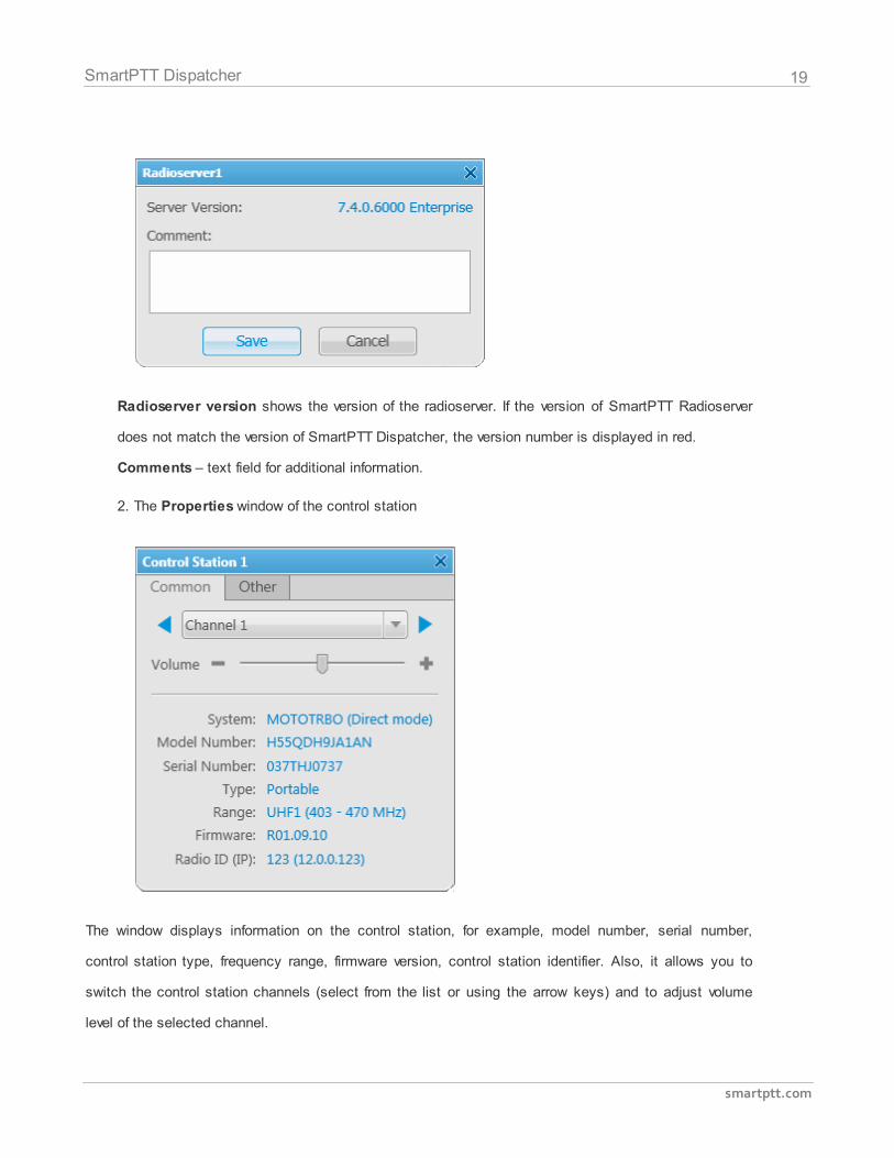
1. The Properties window of the radioserver
19
smartptt.com
SmartPTT Dispatcher
Radioserver version shows the version of the radioserver. If the version of SmartPTT Radioserver
does not match the version of SmartPTT Dispatcher, the version number is displayed in red.
Comments – text field for additional information.
2. The Properties window of the control station
The window displays information on the control station, for example, model number, serial number,
control station type, frequency range, firmware version, control station identifier. Also, it allows you to
switch the control station channels (select from the list or using the arrow keys) and to adjust volume
level of the selected channel.
20
smartptt.com
SmartPTT Dispatcher
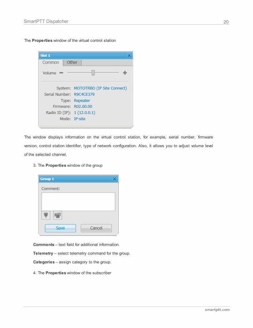
The Properties window of the virtual control station
The window displays information on the virtual control station, for example, serial number, firmware
version, control station identifier, type of network configuration. Also, it allows you to adjust volume level
of the selected channel.
3. The Properties window of the group
Comments – text field for additional information.
Telemetry – select telemetry command for the group.
Categories – assign category to the group.
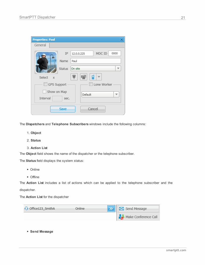
4. The Properties window of the subscriber
21
smartptt.com
SmartPTT Dispatcher
The Dispatchers and Telephone Subscribers windows include the following columns:
1. Object
2. Status
3. Action List
The Object field shows the name of the dispatcher or the telephone subscriber.
The Status field displays the system status:
Online
Offline
The Action List includes a list of actions which can be applied to the telephone subscriber and the
dispatcher.
The Action List for the dispatcher
Send Message
22
smartptt.com
SmartPTT Dispatcher
Make Conference Call
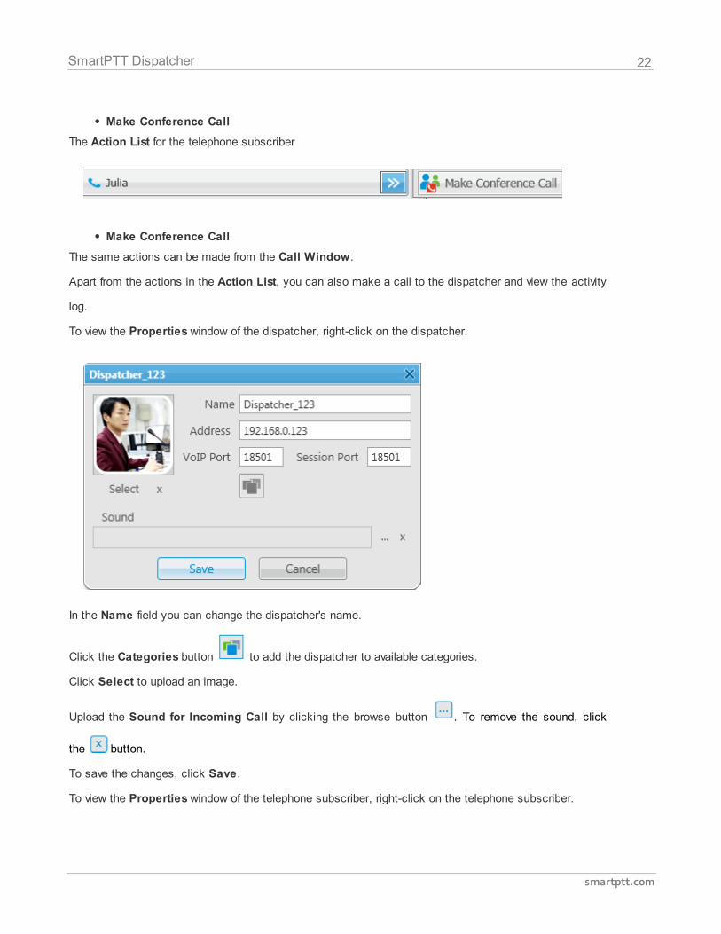
The Action List for the telephone subscriber
Make Conference Call
The same actions can be made from the Call Window.
Apart from the actions in the Action List, you can also make a call to the dispatcher and view the activity
log.
To view the Properties window of the dispatcher, right-click on the dispatcher.
In the Name field you can change the dispatcher's name.
Click the Categories button to add the dispatcher to available categories.
Click Select to upload an image.
Upload the Sound for Incoming Call by clicking the browse button . To remove the sound, click
the button.
To save the changes, click Save.
To view the Properties window of the telephone subscriber, right-click on the telephone subscriber.
23
smartptt.com
SmartPTT Dispatcher
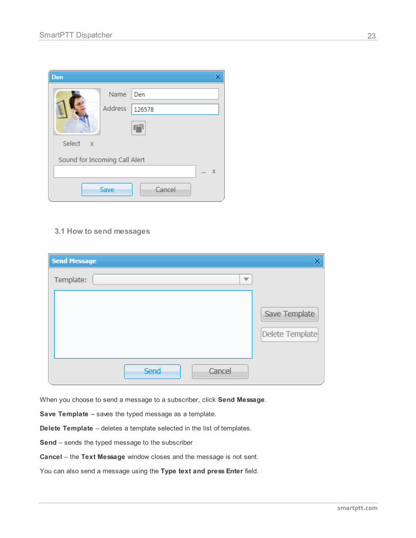
3.1 How to send messages
When you choose to send a message to a subscriber, click Send Message.
Save Template – saves the typed message as a template.
Delete Template – deletes a template selected in the list of templates.
Send – sends the typed message to the subscriber
Cancel – the Text Message window closes and the message is not sent.
You can also send a message using the Type text and press Enter field.
24
smartptt.com
SmartPTT Dispatcher
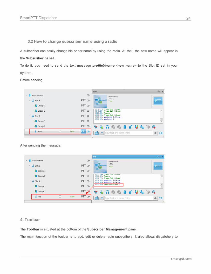
3.2 How to change subscriber name using a radio
A subscriber can easily change his or her name by using the radio. At that, the new name will appear in
the Subscriber panel.
To do it, you need to send the text message profile%name:<new name> to the Slot ID set in your
system.
Before sending:
After sending the message:
4. Toolbar
The Toolbar is situated at the bottom of the Subscriber Management panel.
The main function of the toolbar is to add, edit or delete radio subscribers. It also allows dispatchers to
25
smartptt.com
SmartPTT Dispatcher
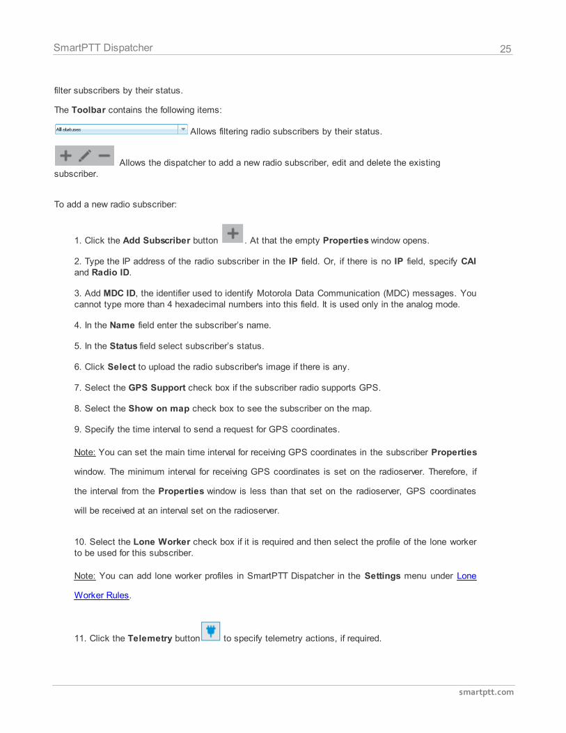
filter subscribers by their status.
The Toolbar contains the following items:
Allows filtering radio subscribers by their status.
Allows the dispatcher to add a new radio subscriber, edit and delete the existingsubscriber.
To add a new radio subscriber:
1. Click the Add Subscriber button . At that the empty Properties window opens.
2. Type the IP address of the radio subscriber in the IP field. Or, if there is no IP field, specify CAIand Radio ID.
3. Add MDC ID, the identifier used to identify Motorola Data Communication (MDC) messages. Youcannot type more than 4 hexadecimal numbers into this field. It is used only in the analog mode.
4. In the Name field enter the subscriber’s name.
5. In the Status field select subscriber’s status.
6. Click Select to upload the radio subscriber's image if there is any.
7. Select the GPS Support check box if the subscriber radio supports GPS.
8. Select the Show on map check box to see the subscriber on the map.
9. Specify the time interval to send a request for GPS coordinates.
Note: You can set the main time interval for receiving GPS coordinates in the subscriber Properties
window. The minimum interval for receiving GPS coordinates is set on the radioserver. Therefore, if
the interval from the Properties window is less than that set on the radioserver, GPS coordinates
will be received at an interval set on the radioserver.
10. Select the Lone Worker check box if it is required and then select the profile of the lone workerto be used for this subscriber.
Note: You can add lone worker profiles in SmartPTT Dispatcher in the Settings menu under Lone
Worker Rules.
11. Click the Telemetry button to specify telemetry actions, if required.
26
smartptt.com
SmartPTT Dispatcher
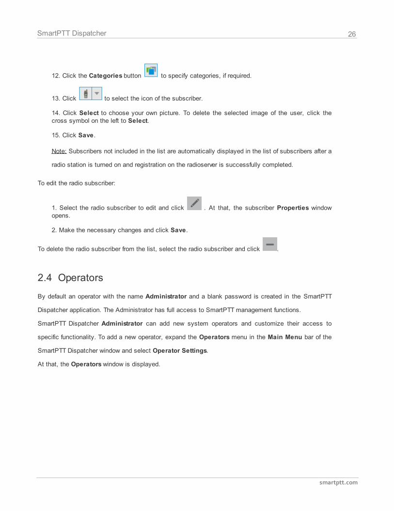
12. Click the Categories button to specify categories, if required.
13. Click to select the icon of the subscriber.
14. Click Select to choose your own picture. To delete the selected image of the user, click thecross symbol on the left to Select.
15. Click Save.
Note: Subscribers not included in the list are automatically displayed in the list of subscribers after a
radio station is turned on and registration on the radioserver is successfully completed.
To edit the radio subscriber:
1. Select the radio subscriber to edit and click . At that, the subscriber Properties windowopens.
2. Make the necessary changes and click Save.
To delete the radio subscriber from the list, select the radio subscriber and click .
2.4 Operators
By default an operator with the name Administrator and a blank password is created in the SmartPTT
Dispatcher application. The Administrator has full access to SmartPTT management functions.
SmartPTT Dispatcher Administrator can add new system operators and customize their access to
specific functionality. To add a new operator, expand the Operators menu in the Main Menu bar of the
SmartPTT Dispatcher window and select Operator Settings.
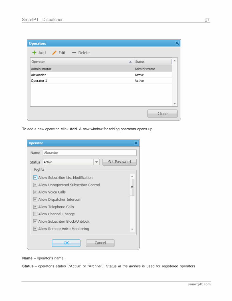
At that, the Operators window is displayed.
27
smartptt.com
SmartPTT Dispatcher
To add a new operator, click Add. A new window for adding operators opens up.
Name – operator’s name.
Status – operator’s status ("Active" or "Archive"). Status in the archive is used for registered operators
28
smartptt.com
SmartPTT Dispatcher
which are not used any longer, but cannot be removed from the system as the event log contains entries
referring to them.
Rights – a list of permissions which can be selected or cleared for each operator individually.
Here are some of them:
Allow Subscriber List Modification – the permission allows the operator to add, delete subscribers and
modify their properties.
Allow Unregistered Subscriber Control – select this property to allow operator to modify unregistered
subscribers in the subscriber tree.
Register Subscribers on Selected Control Station – select control stations which will be used to
display all registered subscribers. This option is recommended to be set for Capacity Plus systems.
Set/Change Password – set new operator's password or change the old one.
To edit an operator, select it in the list of operators and click Edit. The edit window is displayed where
you can change Name, Status and Password parameters.
To delete an operator from the operators list, select it and click Delete.
Note: You cannot delete the Administrator from the system.
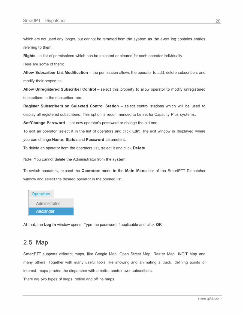
To switch operators, expand the Operators menu in the Main Menu bar of the SmartPTT Dispatcher
window and select the desired operator in the opened list.
At that, the Log In window opens. Type the password if applicable and click OK.
2.5 Map
SmartPTT supports different maps, like Google Map, Open Street Map, Raster Map, INGIT Map and
many others. Together with many useful tools like showing and animating a track, defining points of
interest, maps provide the dispatcher with a better control over subscribers.
There are two types of maps: online and offline maps.
29
smartptt.com
SmartPTT Dispatcher
Online maps are always accessible (if you have the Internet connection). They are Google Map and Open
Street Map.
The rest of the maps are Offline. They are not available by default and should be opened.
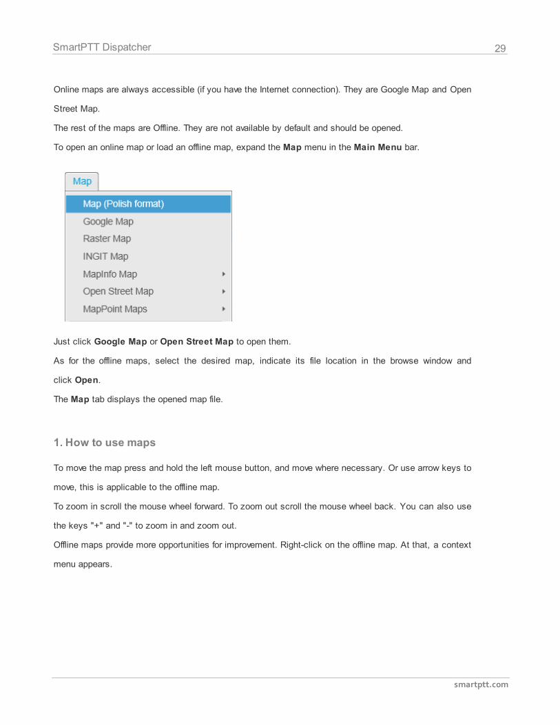
To open an online map or load an offline map, expand the Map menu in the Main Menu bar.
Just click Google Map or Open Street Map to open them.
As for the offline maps, select the desired map, indicate its file location in the browse window and
click Open.
The Map tab displays the opened map file.
1. How to use maps
To move the map press and hold the left mouse button, and move where necessary. Or use arrow keys to
move, this is applicable to the offline map.
To zoom in scroll the mouse wheel forward. To zoom out scroll the mouse wheel back. You can also use
the keys "+" and "-" to zoom in and zoom out.
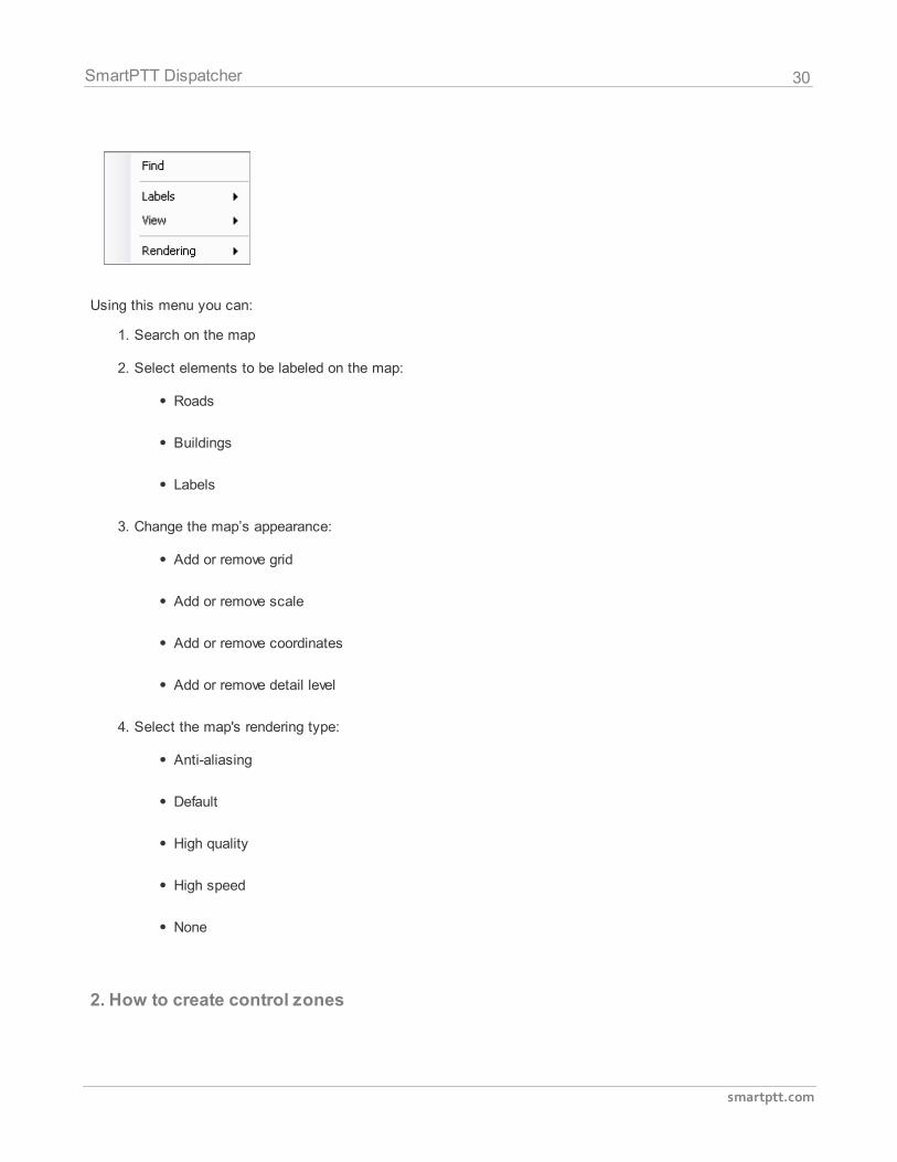
Offline maps provide more opportunities for improvement. Right-click on the offline map. At that, a context
menu appears.
30
smartptt.com
SmartPTT Dispatcher
Using this menu you can:
1. Search on the map
2. Select elements to be labeled on the map:
Roads
Buildings
Labels
3. Change the map’s appearance:
Add or remove grid
Add or remove scale
Add or remove coordinates
Add or remove detail level
4. Select the map's rendering type:
Anti-aliasing
Default
High quality
High speed
None
2. How to create control zones
31
smartptt.com
SmartPTT Dispatcher
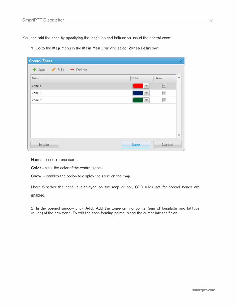
You can add the zone by specifying the longitude and latitude values of the control zone:
1. Go to the Map menu in the Main Menu bar and select Zones Definition.
Name – control zone name.
Color – sets the color of the control zone.
Show – enables the option to display the zone on the map.
Note: Whether the zone is displayed on the map or not, GPS rules set for control zones are
enabled.
2. In the opened window click Add. Add the zone-forming points (pair of longitude and latitudevalues) of the new zone. To edit the zone-forming points, place the cursor into the fields.
32
smartptt.com
SmartPTT Dispatcher
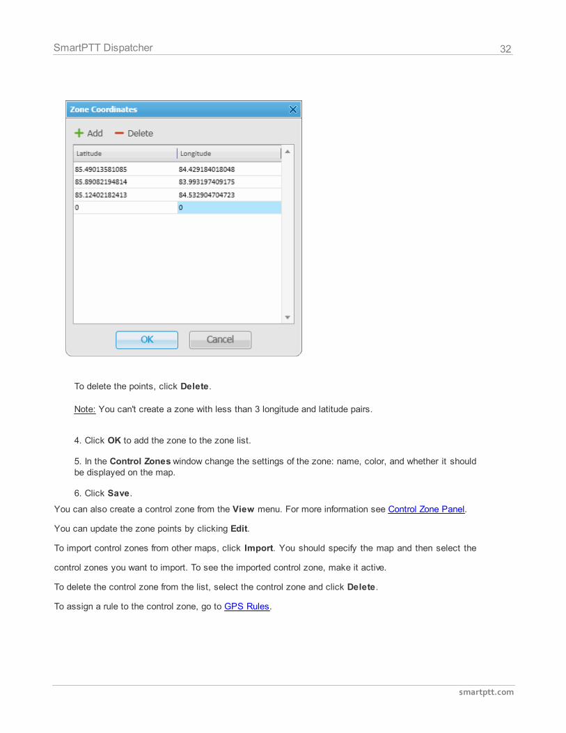
To delete the points, click Delete.
Note: You can't create a zone with less than 3 longitude and latitude pairs.
4. Click OK to add the zone to the zone list.
5. In the Control Zones window change the settings of the zone: name, color, and whether it shouldbe displayed on the map.
6. Click Save.
You can also create a control zone from the View menu. For more information see Control Zone Panel.
You can update the zone points by clicking Edit.
To import control zones from other maps, click Import. You should specify the map and then select the
control zones you want to import. To see the imported control zone, make it active.
To delete the control zone from the list, select the control zone and click Delete.
To assign a rule to the control zone, go to GPS Rules.
33
smartptt.com
SmartPTT Dispatcher
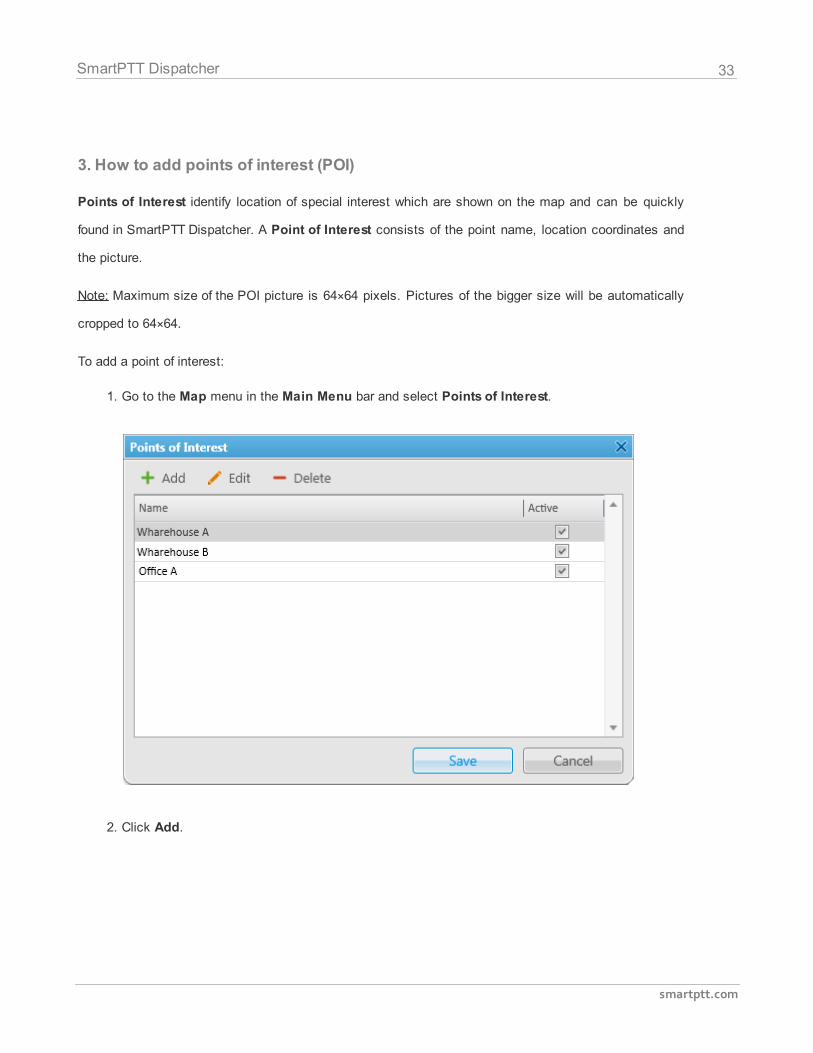
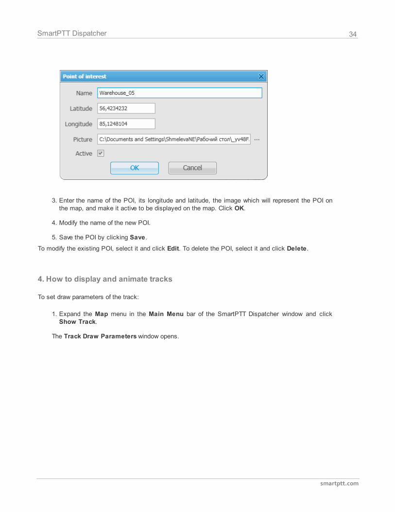
3. How to add points of interest (POI)
Points of Interest identify location of special interest which are shown on the map and can be quickly
found in SmartPTT Dispatcher. A Point of Interest consists of the point name, location coordinates and
the picture.
Note: Maximum size of the POI picture is 64×64 pixels. Pictures of the bigger size will be automatically
cropped to 64×64.
To add a point of interest:
1. Go to the Map menu in the Main Menu bar and select Points of Interest.
2. Click Add.
34
smartptt.com
SmartPTT Dispatcher
3. Enter the name of the POI, its longitude and latitude, the image which will represent the POI onthe map, and make it active to be displayed on the map. Click OK.
4. Modify the name of the new POI.
5. Save the POI by clicking Save.
To modify the existing POI, select it and click Edit. To delete the POI, select it and click Delete.
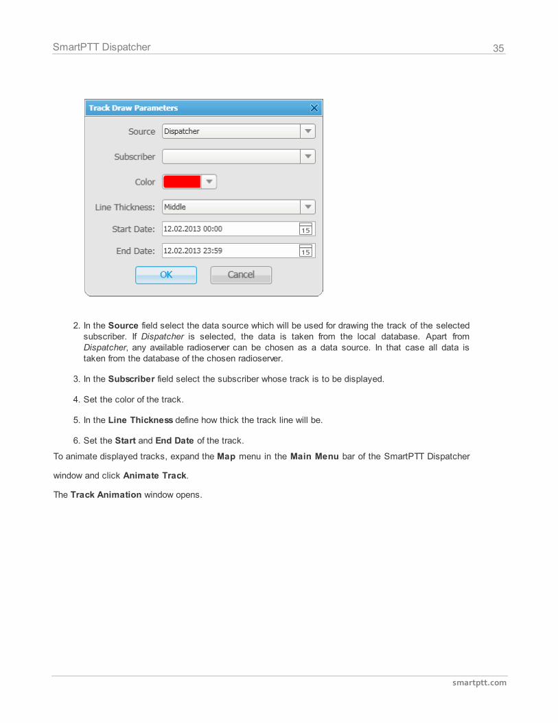
4. How to display and animate tracks
To set draw parameters of the track:
1. Expand the Map menu in the Main Menu bar of the SmartPTT Dispatcher window and clickShow Track.
The Track Draw Parameters window opens.
35
smartptt.com
SmartPTT Dispatcher
2. In the Source field select the data source which will be used for drawing the track of the selectedsubscriber. If Dispatcher is selected, the data is taken from the local database. Apart fromDispatcher, any available radioserver can be chosen as a data source. In that case all data istaken from the database of the chosen radioserver.
3. In the Subscriber field select the subscriber whose track is to be displayed.
4. Set the color of the track.
5. In the Line Thickness define how thick the track line will be.
6. Set the Start and End Date of the track.
To animate displayed tracks, expand the Map menu in the Main Menu bar of the SmartPTT Dispatcher
window and click Animate Track.
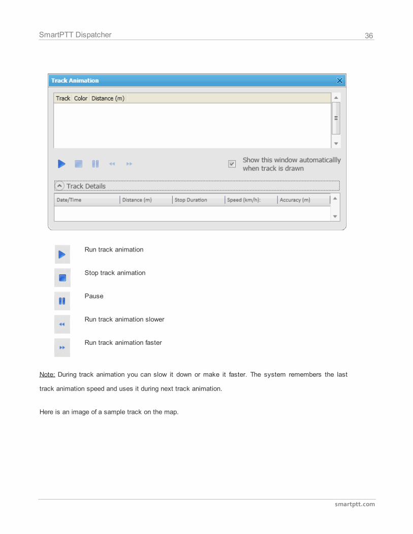
The Track Animation window opens.
36
smartptt.com
SmartPTT Dispatcher
Run track animation
Stop track animation
Pause
Run track animation slower
Run track animation faster
Note: During track animation you can slow it down or make it faster. The system remembers the last
track animation speed and uses it during next track animation.
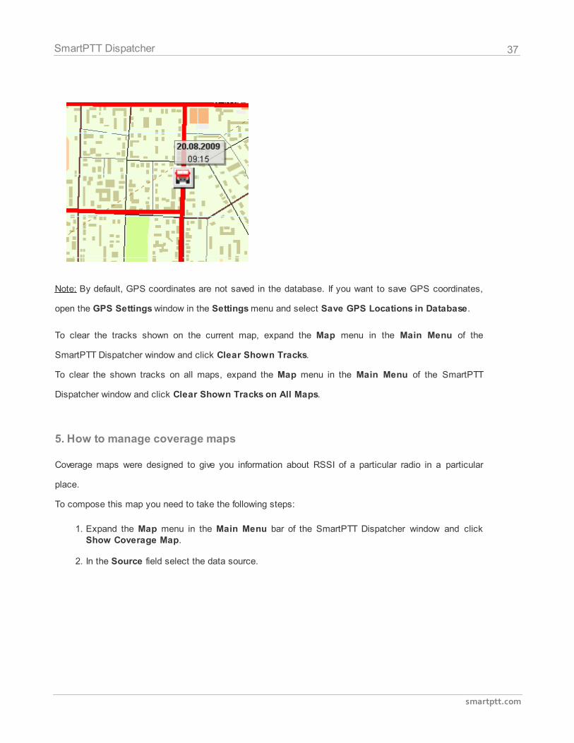
Here is an image of a sample track on the map.
37
smartptt.com
SmartPTT Dispatcher
Note: By default, GPS coordinates are not saved in the database. If you want to save GPS coordinates,
open the GPS Settings window in the Settings menu and select Save GPS Locations in Database.
To clear the tracks shown on the current map, expand the Map menu in the Main Menu of the
SmartPTT Dispatcher window and click Clear Shown Tracks.
To clear the shown tracks on all maps, expand the Map menu in the Main Menu of the SmartPTT
Dispatcher window and click Clear Shown Tracks on All Maps.
5. How to manage coverage maps
Coverage maps were designed to give you information about RSSI of a particular radio in a particular
place.
To compose this map you need to take the following steps:
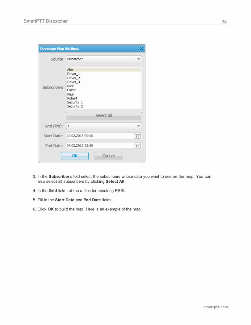
1. Expand the Map menu in the Main Menu bar of the SmartPTT Dispatcher window and clickShow Coverage Map.
2. In the Source field select the data source.
38
smartptt.com
SmartPTT Dispatcher
3. In the Subscribers field select the subscribers whose data you want to see on the map. You canalso select all subscribers by clicking Select All.
4. In the Grid field set the radius for checking RSSI.
5. Fill in the Start Date and End Date fields.
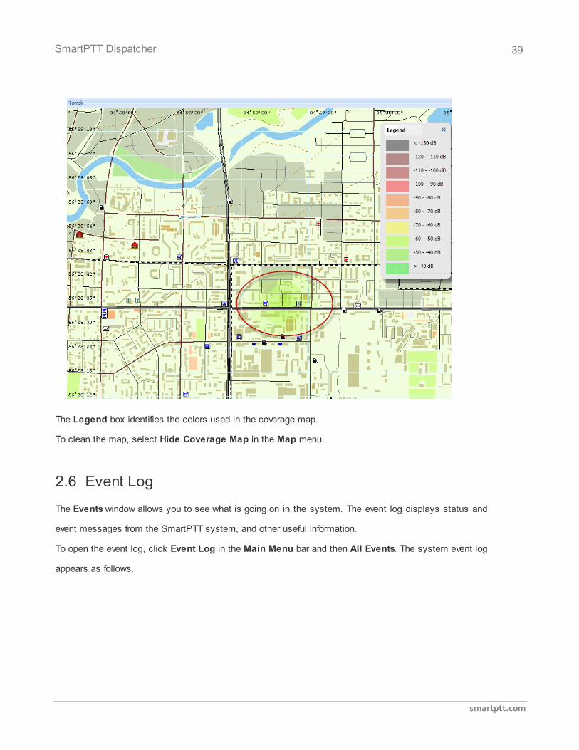
6. Click OK to build the map. Here is an example of the map.
39
smartptt.com
SmartPTT Dispatcher
The Legend box identifies the colors used in the coverage map.
To clean the map, select Hide Coverage Map in the Map menu.
2.6 Event Log
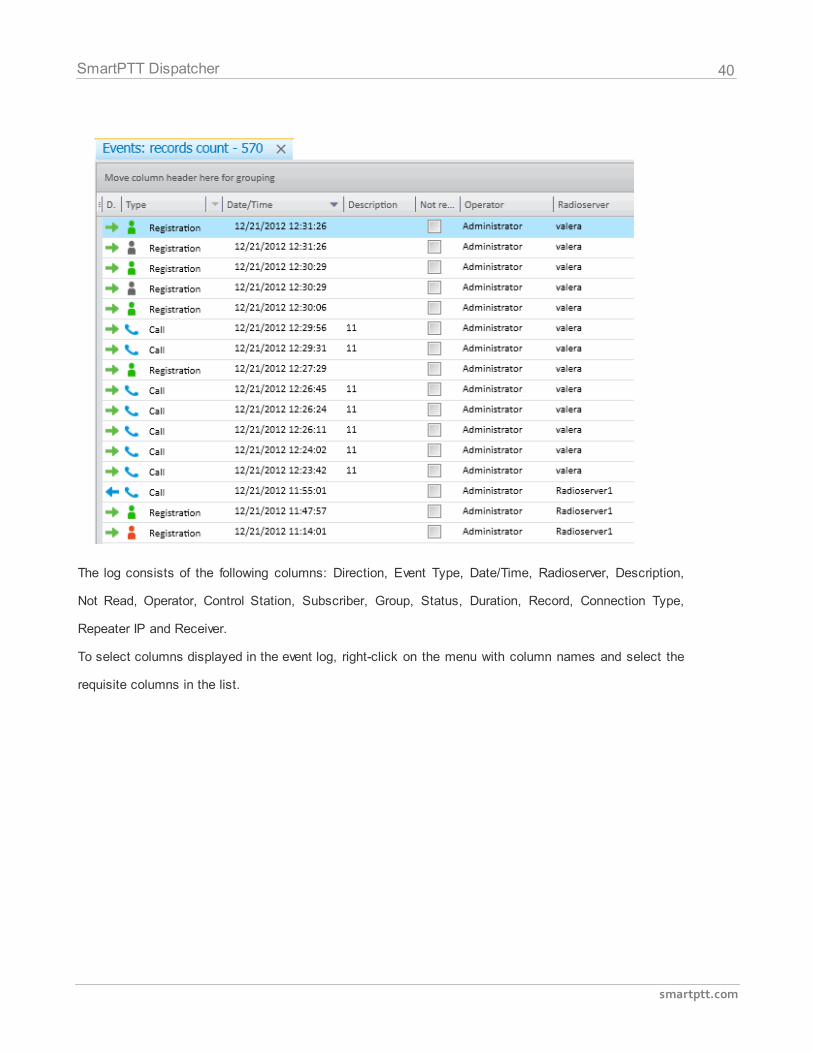
The Events window allows you to see what is going on in the system. The event log displays status and
event messages from the SmartPTT system, and other useful information.
To open the event log, click Event Log in the Main Menu bar and then All Events. The system event log
appears as follows.
40
smartptt.com
SmartPTT Dispatcher
The log consists of the following columns: Direction, Event Type, Date/Time, Radioserver, Description,
Not Read, Operator, Control Station, Subscriber, Group, Status, Duration, Record, Connection Type,
Repeater IP and Receiver.
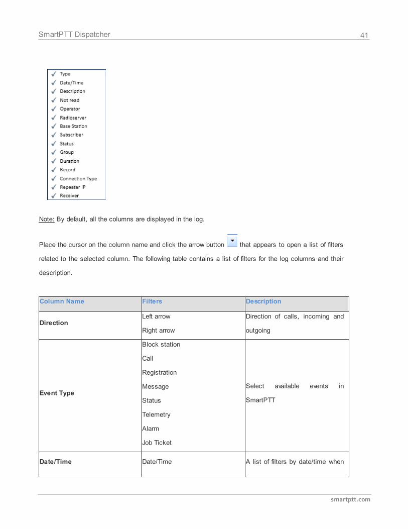
To select columns displayed in the event log, right-click on the menu with column names and select the
requisite columns in the list.
41
smartptt.com
SmartPTT Dispatcher
Note: By default, all the columns are displayed in the log.
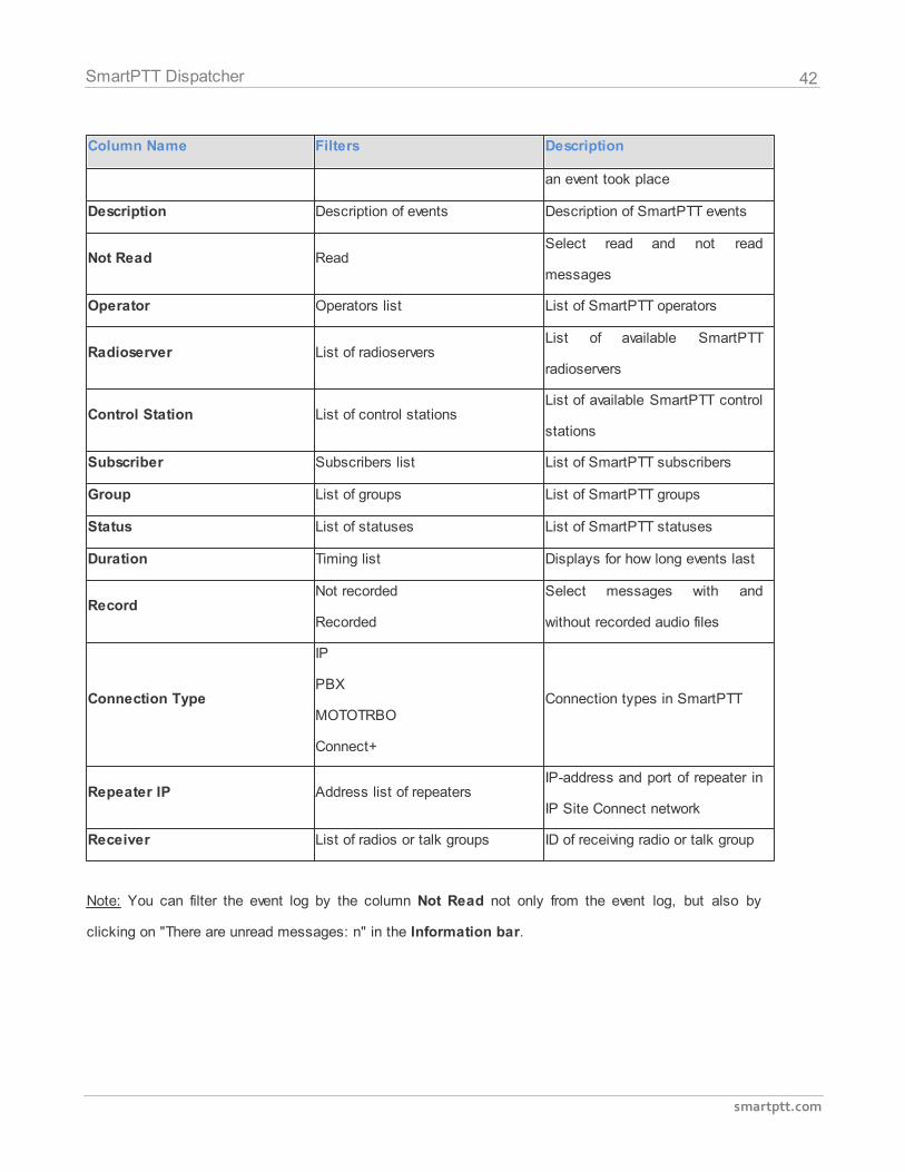
Place the cursor on the column name and click the arrow button that appears to open a list of filters
related to the selected column. The following table contains a list of filters for the log columns and their
description.
Column Name Filters Description
DirectionLeft arrow
Right arrow
Direction of calls, incoming and
outgoing
Event Type
Block station
Call
Registration
Message
Status
Telemetry
Alarm
Job Ticket
Select available events in
SmartPTT
Date/Time Date/Time A list of filters by date/time when
42
smartptt.com
SmartPTT Dispatcher
Column Name Filters Description
an event took place
Description Description of events Description of SmartPTT events
Not Read ReadSelect read and not read
messages
Operator Operators list List of SmartPTT operators
Radioserver List of radioserversList of available SmartPTT
radioservers
Control Station List of control stationsList of available SmartPTT control
stations
Subscriber Subscribers list List of SmartPTT subscribers
Group List of groups List of SmartPTT groups
Status List of statuses List of SmartPTT statuses
Duration Timing list Displays for how long events last
RecordNot recorded
Recorded
Select messages with and
without recorded audio files
Connection Type
IP
PBX
MOTOTRBO
Connect+
Connection types in SmartPTT
Repeater IP Address list of repeatersIP-address and port of repeater in
IP Site Connect network
Receiver List of radios or talk groups ID of receiving radio or talk group
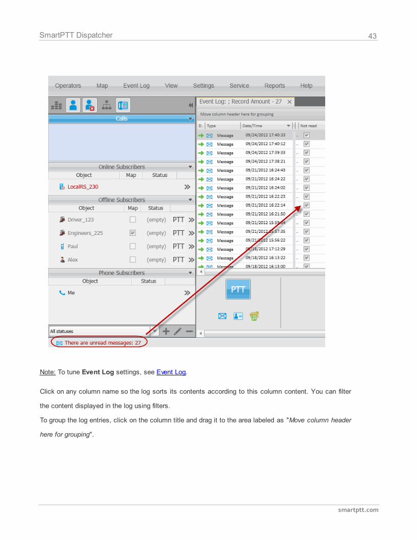
Note: You can filter the event log by the column Not Read not only from the event log, but also by
clicking on "There are unread messages: n" in the Information bar.
43
smartptt.com
SmartPTT Dispatcher
Note: To tune Event Log settings, see Event Log.
Click on any column name so the log sorts its contents according to this column content. You can filter
the content displayed in the log using filters.
To group the log entries, click on the column title and drag it to the area labeled as "Move column header
here for grouping".
44
smartptt.com
SmartPTT Dispatcher
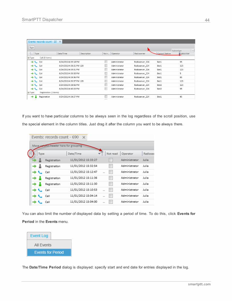
If you want to have particular columns to be always seen in the log regardless of the scroll position, use
the special element in the column titles. Just drag it after the column you want to be always there.
You can also limit the number of displayed data by setting a period of time. To do this, click Events for
Period in the Events menu.
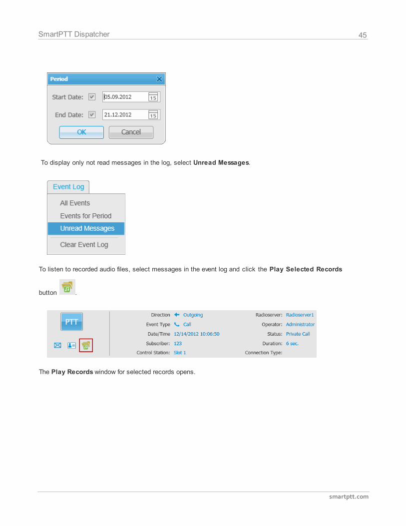
The Date/Time Period dialog is displayed: specify start and end date for entries displayed in the log.
45
smartptt.com
SmartPTT Dispatcher
To display only not read messages in the log, select Unread Messages.
To listen to recorded audio files, select messages in the event log and click the Play Selected Records
button .
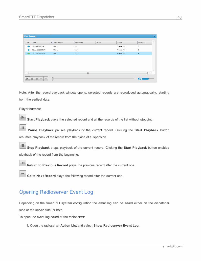
The Play Records window for selected records opens.
46
smartptt.com
SmartPTT Dispatcher
Note: After the record playback window opens, selected records are reproduced automatically, starting
from the earliest date.
Player buttons:
Start Playback plays the selected record and all the records of the list without stopping.
Pause Playback pauses playback of the current record. Clicking the Start Playback button
resumes playback of the record from the place of suspension.
Stop Playback stops playback of the current record. Clicking the Start Playback button enables
playback of the record from the beginning.
Return to Previous Record plays the previous record after the current one.
Go to Next Record plays the following record after the current one.
Opening Radioserver Event Log
Depending on the SmartPTT system configuration the event log can be saved either on the dispatcher
side or the server side, or both.
To open the event log saved at the radioserver:
1. Open the radioserver Action List and select Show Radioserver Event Log.
47
smartptt.com
SmartPTT Dispatcher
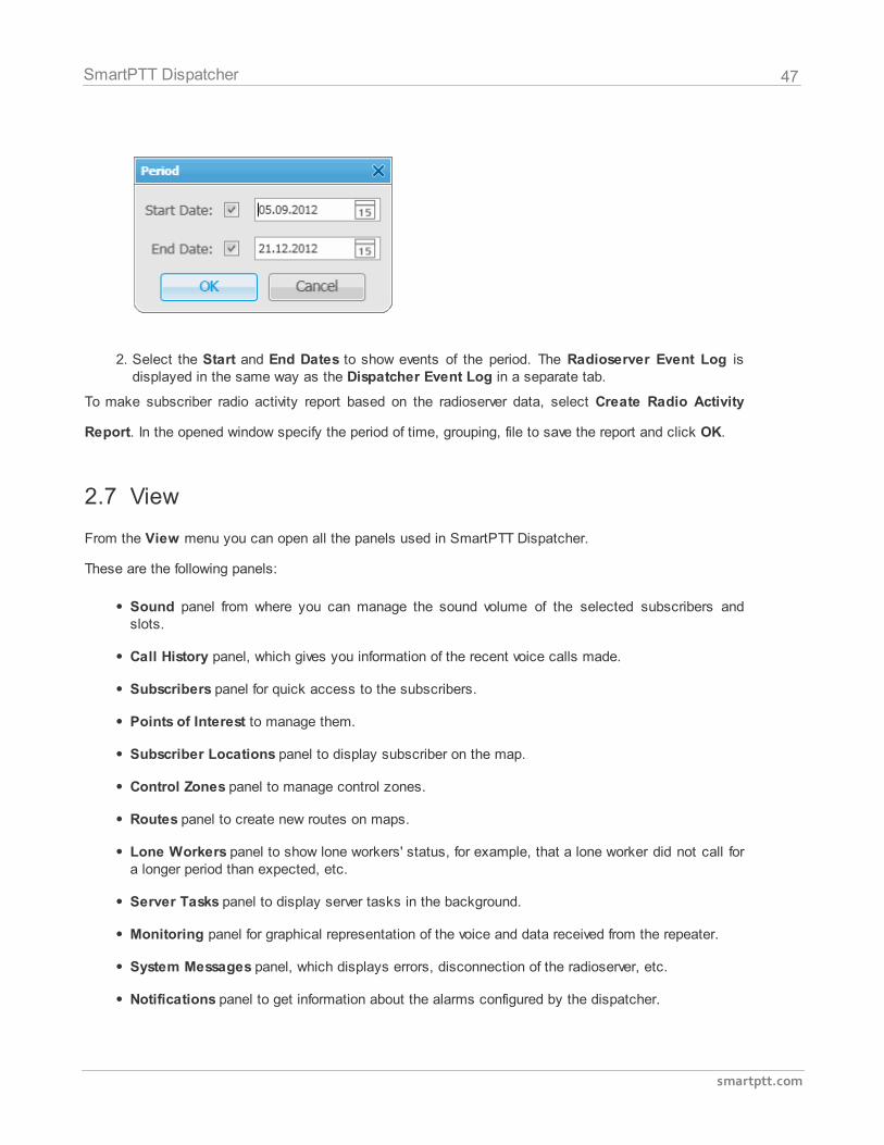
2. Select the Start and End Dates to show events of the period. The Radioserver Event Log isdisplayed in the same way as the Dispatcher Event Log in a separate tab.
To make subscriber radio activity report based on the radioserver data, select Create Radio Activity
Report. In the opened window specify the period of time, grouping, file to save the report and click OK.
2.7 View
From the View menu you can open all the panels used in SmartPTT Dispatcher.
These are the following panels:
Sound panel from where you can manage the sound volume of the selected subscribers andslots.
Call History panel, which gives you information of the recent voice calls made.
Subscribers panel for quick access to the subscribers.
Points of Interest to manage them.
Subscriber Locations panel to display subscriber on the map.
Control Zones panel to manage control zones.
Routes panel to create new routes on maps.
Lone Workers panel to show lone workers' status, for example, that a lone worker did not call fora longer period than expected, etc.
Server Tasks panel to display server tasks in the background.
Monitoring panel for graphical representation of the voice and data received from the repeater.
System Messages panel, which displays errors, disconnection of the radioserver, etc.
Notifications panel to get information about the alarms configured by the dispatcher.
48
smartptt.com
SmartPTT Dispatcher
Job Tickets panel from where you can create and supervise job tickets.
Custom panels.
2.7.1 Sound Panel
The Sound Panel allows setting individual sound level for each control station, turn on/off sound for
subscriber or group, select only one control station with the sound turned on.
To open the Sound Panel, expand the View menu in the Main Menu bar of the SmartPTT Dispatcher
window and click Sound Panel.
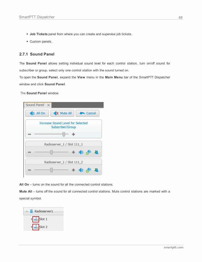
The Sound Panel window.
All On – turns on the sound for all the connected control stations.
Mute All – turns off the sound for all connected control stations. Mute control stations are marked with a
special symbol.
49
smartptt.com
SmartPTT Dispatcher
Cancel – calls off the last action.
To manipulate the sound level, click the – / + buttons or move the thumb.
To turn on/off the sound on a particular control station, click .
To turn on the sound for one control station and at the same time to turn off the sound for other control
stations, click .
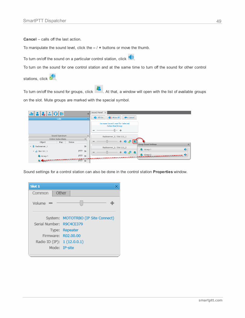
To turn on/off the sound for groups, click . At that, a window will open with the list of available groups
on the slot. Mute groups are marked with the special symbol.
Sound settings for a control station can also be done in the control station Properties window.
50
smartptt.com
SmartPTT Dispatcher
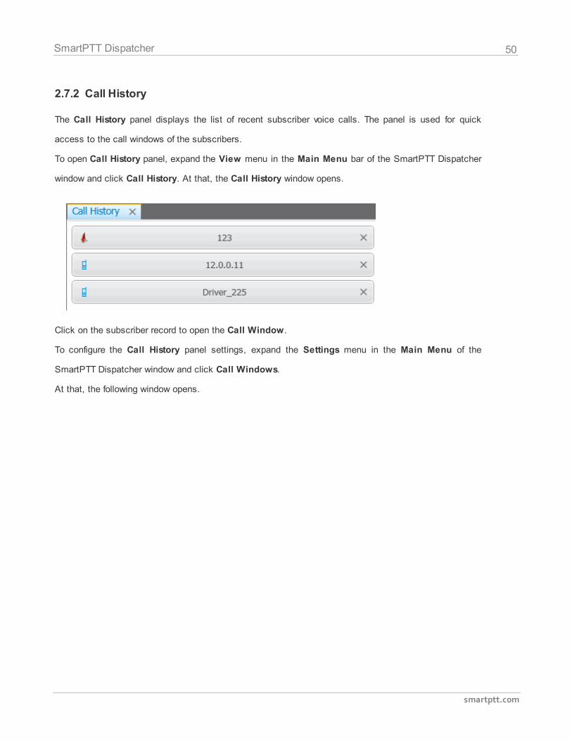
2.7.2 Call History
The Call History panel displays the list of recent subscriber voice calls. The panel is used for quick
access to the call windows of the subscribers.
To open Call History panel, expand the View menu in the Main Menu bar of the SmartPTT Dispatcher
window and click Call History. At that, the Call History window opens.
Click on the subscriber record to open the Call Window.
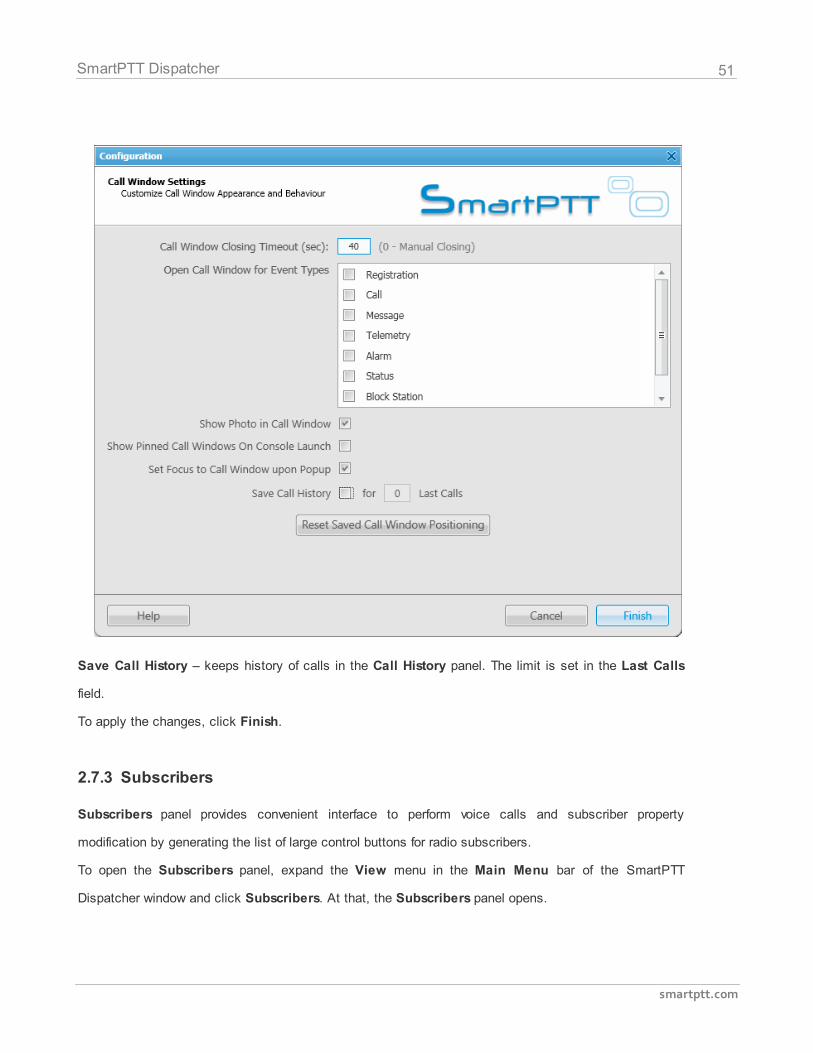
To configure the Call History panel settings, expand the Settings menu in the Main Menu of the
SmartPTT Dispatcher window and click Call Windows.
At that, the following window opens.
51
smartptt.com
SmartPTT Dispatcher
Save Call History – keeps history of calls in the Call History panel. The limit is set in the Last Calls
field.
To apply the changes, click Finish.
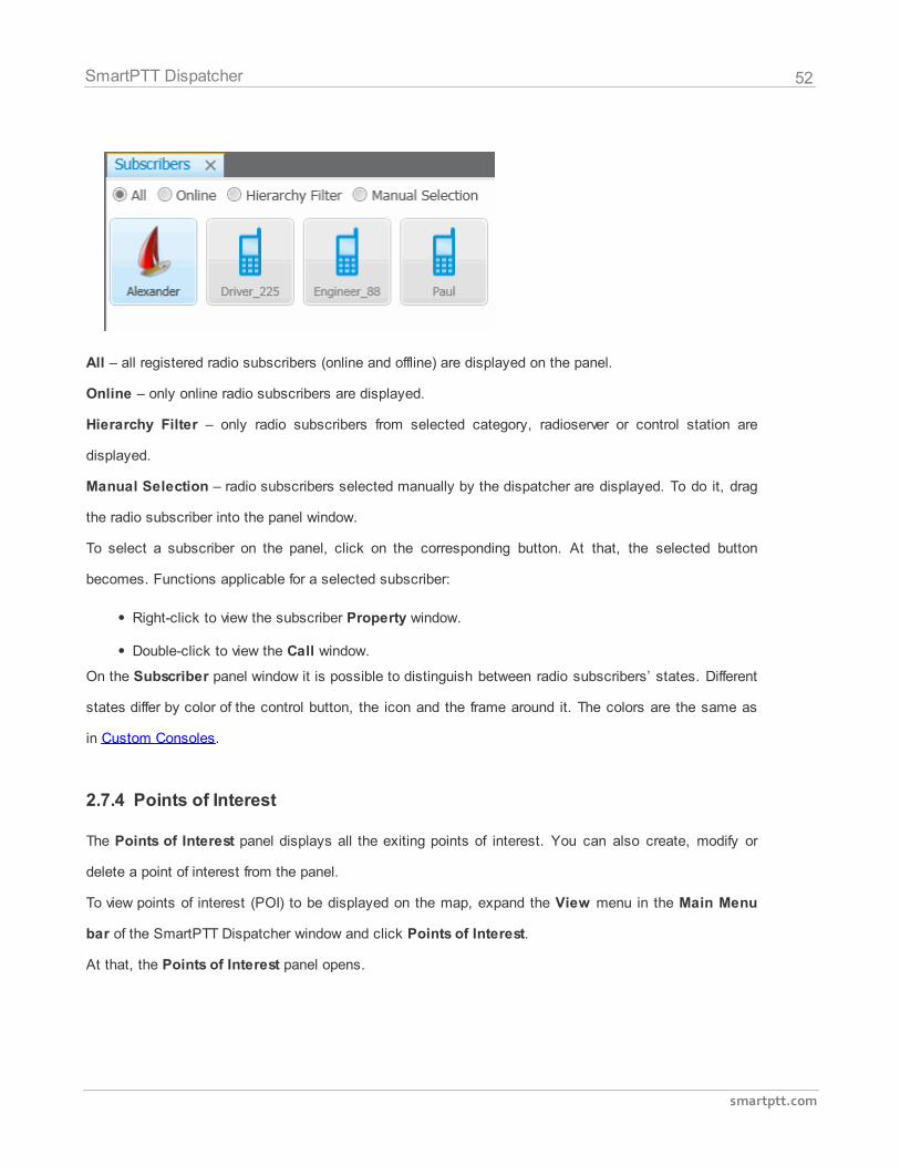
2.7.3 Subscribers
Subscribers panel provides convenient interface to perform voice calls and subscriber property
modification by generating the list of large control buttons for radio subscribers.
To open the Subscribers panel, expand the View menu in the Main Menu bar of the SmartPTT
Dispatcher window and click Subscribers. At that, the Subscribers panel opens.
52
smartptt.com
SmartPTT Dispatcher
All – all registered radio subscribers (online and offline) are displayed on the panel.
Online – only online radio subscribers are displayed.
Hierarchy Filter – only radio subscribers from selected category, radioserver or control station are
displayed.
Manual Selection – radio subscribers selected manually by the dispatcher are displayed. To do it, drag
the radio subscriber into the panel window.
To select a subscriber on the panel, click on the corresponding button. At that, the selected button
becomes. Functions applicable for a selected subscriber:
Right-click to view the subscriber Property window.
Double-click to view the Call window.
On the Subscriber panel window it is possible to distinguish between radio subscribers’ states. Different
states differ by color of the control button, the icon and the frame around it. The colors are the same as
in Custom Consoles.
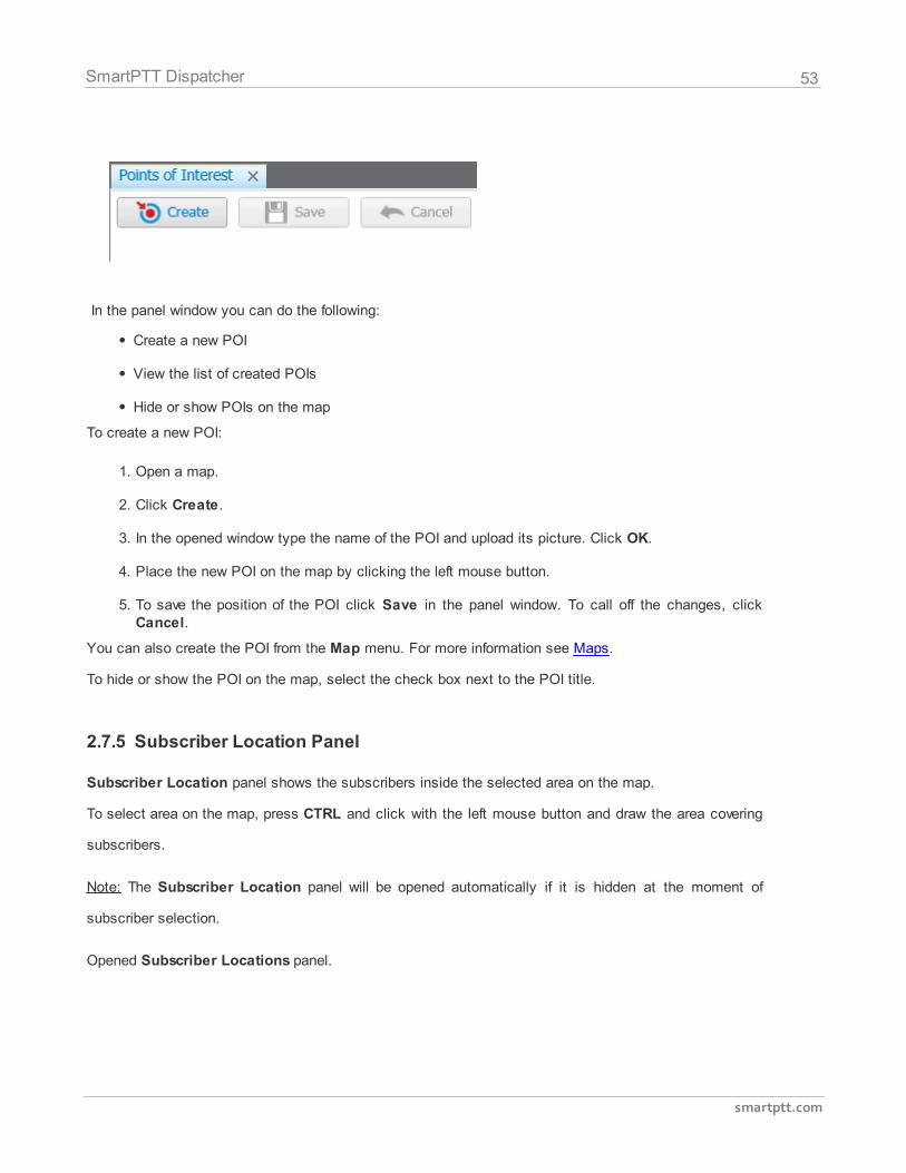
2.7.4 Points of Interest
The Points of Interest panel displays all the exiting points of interest. You can also create, modify or
delete a point of interest from the panel.
To view points of interest (POI) to be displayed on the map, expand the View menu in the Main Menu
bar of the SmartPTT Dispatcher window and click Points of Interest.
At that, the Points of Interest panel opens.
53
smartptt.com
SmartPTT Dispatcher
In the panel window you can do the following:
Create a new POI
View the list of created POIs
Hide or show POIs on the map
To create a new POI:
1. Open a map.
2. Click Create.
3. In the opened window type the name of the POI and upload its picture. Click OK.
4. Place the new POI on the map by clicking the left mouse button.
5. To save the position of the POI click Save in the panel window. To call off the changes, clickCancel.
You can also create the POI from the Map menu. For more information see Maps.
To hide or show the POI on the map, select the check box next to the POI title.
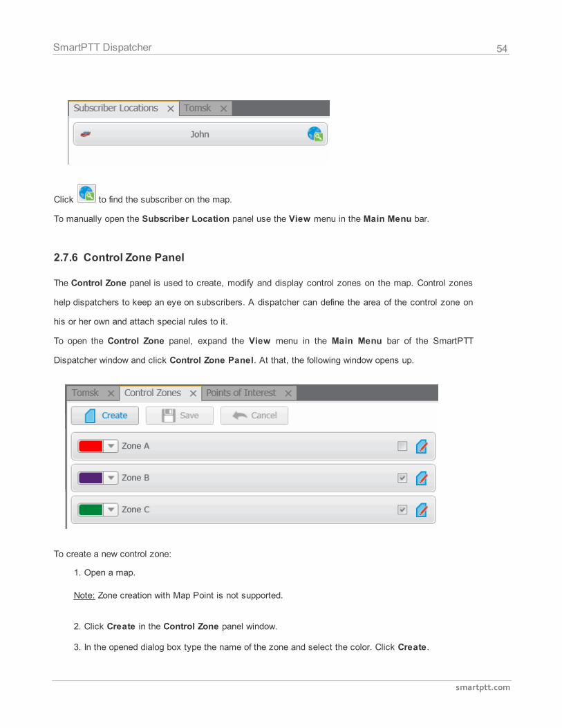
2.7.5 Subscriber Location Panel
Subscriber Location panel shows the subscribers inside the selected area on the map.
To select area on the map, press CTRL and click with the left mouse button and draw the area covering
subscribers.
Note: The Subscriber Location panel will be opened automatically if it is hidden at the moment of
subscriber selection.
Opened Subscriber Locations panel.
54
smartptt.com
SmartPTT Dispatcher
Click to find the subscriber on the map.
To manually open the Subscriber Location panel use the View menu in the Main Menu bar.
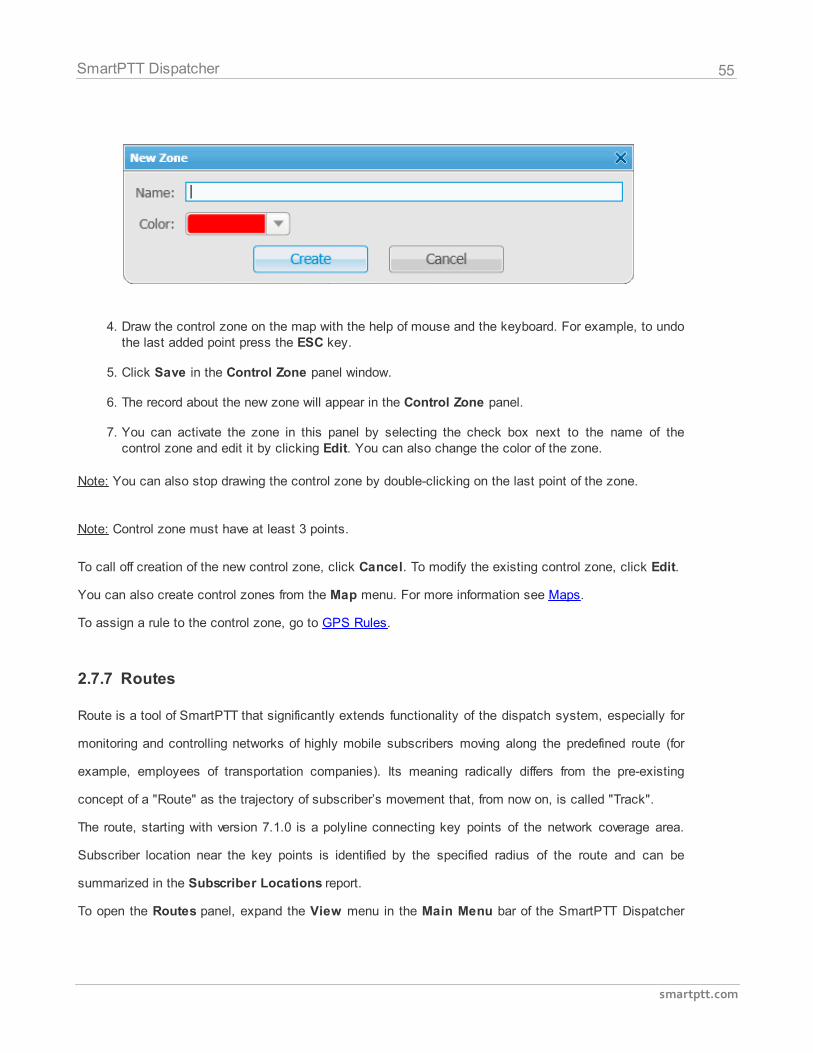
2.7.6 Control Zone Panel
The Control Zone panel is used to create, modify and display control zones on the map. Control zones
help dispatchers to keep an eye on subscribers. A dispatcher can define the area of the control zone on
his or her own and attach special rules to it.
To open the Control Zone panel, expand the View menu in the Main Menu bar of the SmartPTT
Dispatcher window and click Control Zone Panel. At that, the following window opens up.
To create a new control zone:
1. Open a map.
Note: Zone creation with Map Point is not supported.
2. Click Create in the Control Zone panel window.
3. In the opened dialog box type the name of the zone and select the color. Click Create.
55
smartptt.com
SmartPTT Dispatcher
4. Draw the control zone on the map with the help of mouse and the keyboard. For example, to undothe last added point press the ESC key.
5. Click Save in the Control Zone panel window.
6. The record about the new zone will appear in the Control Zone panel.
7. You can activate the zone in this panel by selecting the check box next to the name of thecontrol zone and edit it by clicking Edit. You can also change the color of the zone.
Note: You can also stop drawing the control zone by double-clicking on the last point of the zone.
Note: Control zone must have at least 3 points.
To call off creation of the new control zone, click Cancel. To modify the existing control zone, click Edit.
You can also create control zones from the Map menu. For more information see Maps.
To assign a rule to the control zone, go to GPS Rules.
2.7.7 Routes
Route is a tool of SmartPTT that significantly extends functionality of the dispatch system, especially for
monitoring and controlling networks of highly mobile subscribers moving along the predefined route (for
example, employees of transportation companies). Its meaning radically differs from the pre-existing
concept of a "Route" as the trajectory of subscriber’s movement that, from now on, is called "Track".
The route, starting with version 7.1.0 is a polyline connecting key points of the network coverage area.
Subscriber location near the key points is identified by the specified radius of the route and can be
summarized in the Subscriber Locations report.
To open the Routes panel, expand the View menu in the Main Menu bar of the SmartPTT Dispatcher
56
smartptt.com
SmartPTT Dispatcher
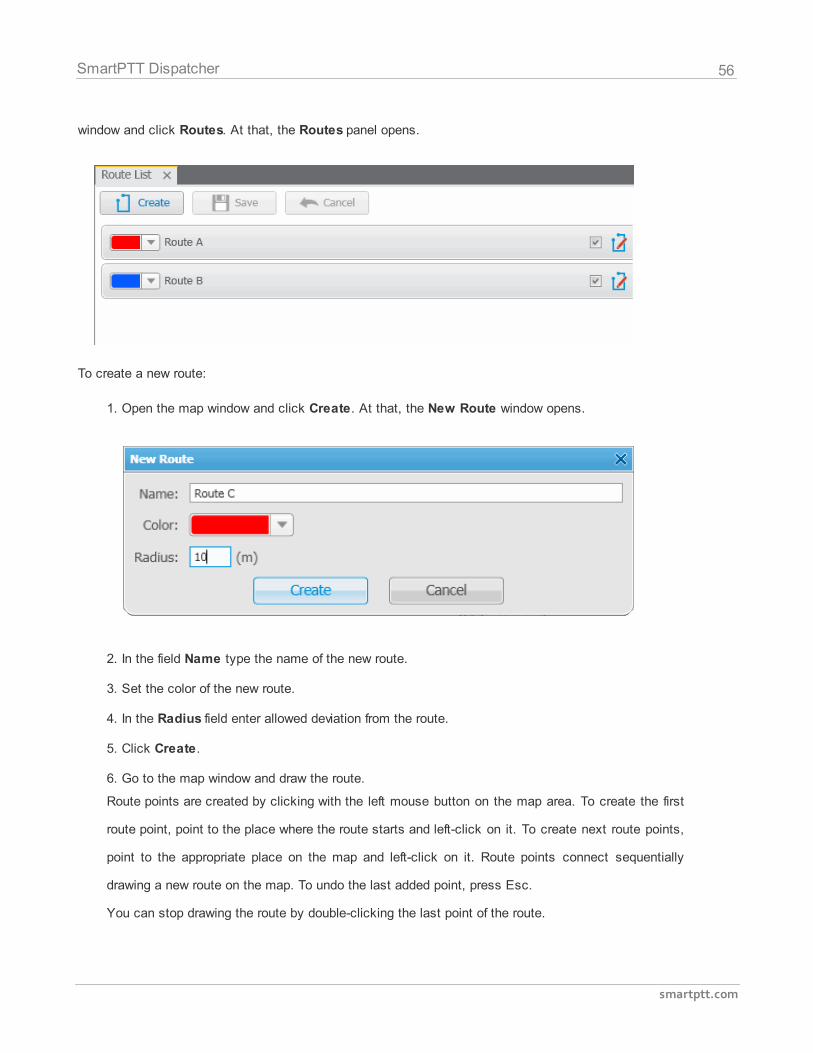
window and click Routes. At that, the Routes panel opens.
To create a new route:
1. Open the map window and click Create. At that, the New Route window opens.
2. In the field Name type the name of the new route.
3. Set the color of the new route.
4. In the Radius field enter allowed deviation from the route.
5. Click Create.
6. Go to the map window and draw the route.
Route points are created by clicking with the left mouse button on the map area. To create the first
route point, point to the place where the route starts and left-click on it. To create next route points,
point to the appropriate place on the map and left-click on it. Route points connect sequentially
drawing a new route on the map. To undo the last added point, press Esc.
You can stop drawing the route by double-clicking the last point of the route.
57
smartptt.com
SmartPTT Dispatcher
7. To save the route, click Save in the Routes panel window. To call off the route, click Cancel. To
modify the existing route, click the Edit button .
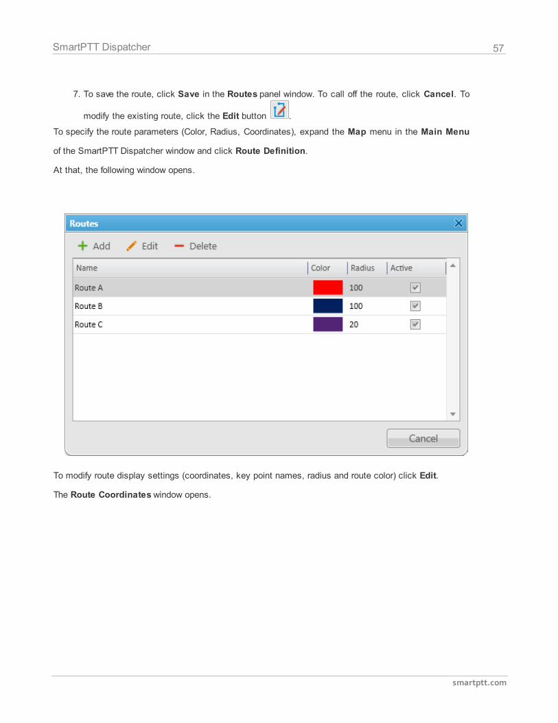
To specify the route parameters (Color, Radius, Coordinates), expand the Map menu in the Main Menu
of the SmartPTT Dispatcher window and click Route Definition.
At that, the following window opens.
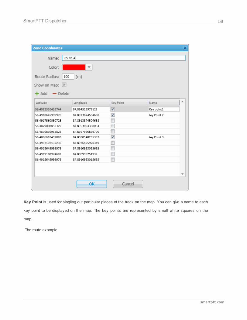
To modify route display settings (coordinates, key point names, radius and route color) click Edit.
The Route Coordinates window opens.
58
smartptt.com
SmartPTT Dispatcher
Key Point is used for singling out particular places of the track on the map. You can give a name to each
key point to be displayed on the map. The key points are represented by small white squares on the
map.
The route example
59
smartptt.com
SmartPTT Dispatcher
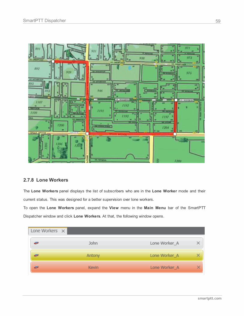
2.7.8 Lone Workers
The Lone Workers panel displays the list of subscribers who are in the Lone Worker mode and their
current status. This was designed for a better supervision over lone workers.
To open the Lone Workers panel, expand the View menu in the Main Menu bar of the SmartPTT
Dispatcher window and click Lone Workers. At that, the following window opens.
60
smartptt.com
SmartPTT Dispatcher
The Lone Workers panel shows radio subscribers working in the Lone Worker mode marked with
specific color. The color shows if the subscriber meets the requirements set for the lone worker profile the
subscriber belongs to:
Light gray – the lone worker did not violate the rule.
Yellow – rule violation: the event, described by the rule, has occurred. Alert Timer starts.
Red – the lone worker did not react in a specified way after Alert Timer expired.
Note: For more information how to set rules for lone workers, please see Lone Worker Rules.
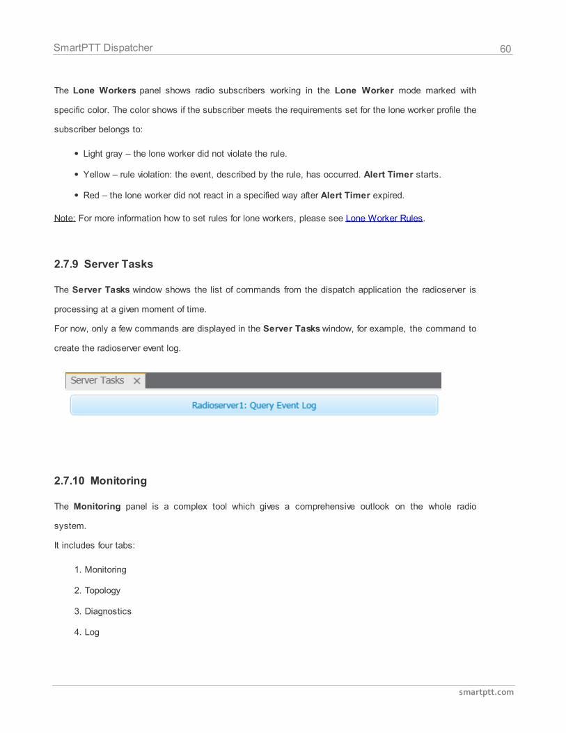
2.7.9 Server Tasks
The Server Tasks window shows the list of commands from the dispatch application the radioserver is
processing at a given moment of time.
For now, only a few commands are displayed in the Server Tasks window, for example, the command to
create the radioserver event log.
2.7.10 Monitoring
The Monitoring panel is a complex tool which gives a comprehensive outlook on the whole radio
system.
It includes four tabs:
1. Monitoring
2. Topology
3. Diagnostics
4. Log
61
smartptt.com
SmartPTT Dispatcher
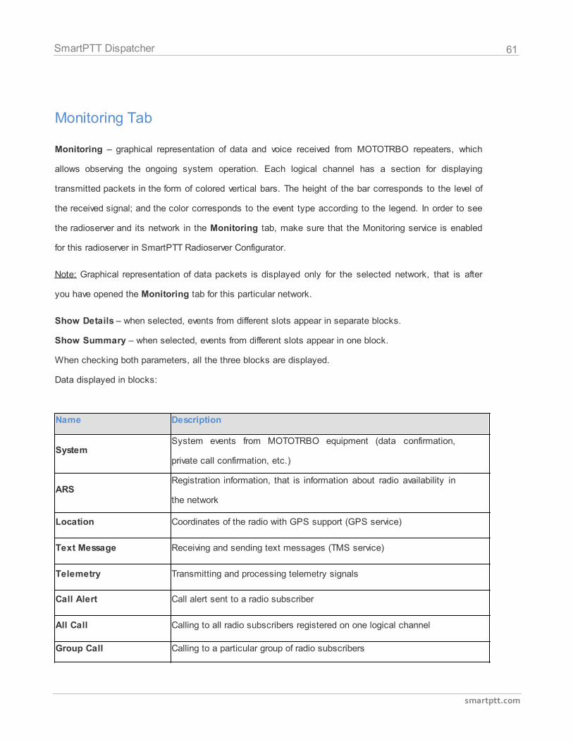
Monitoring Tab
Monitoring – graphical representation of data and voice received from MOTOTRBO repeaters, which
allows observing the ongoing system operation. Each logical channel has a section for displaying
transmitted packets in the form of colored vertical bars. The height of the bar corresponds to the level of
the received signal; and the color corresponds to the event type according to the legend. In order to see
the radioserver and its network in the Monitoring tab, make sure that the Monitoring service is enabled
for this radioserver in SmartPTT Radioserver Configurator.
Note: Graphical representation of data packets is displayed only for the selected network, that is after
you have opened the Monitoring tab for this particular network.
Show Details – when selected, events from different slots appear in separate blocks.
Show Summary – when selected, events from different slots appear in one block.
When checking both parameters, all the three blocks are displayed.
Data displayed in blocks:
Name Description
SystemSystem events from MOTOTRBO equipment (data confirmation,
private call confirmation, etc.)
ARSRegistration information, that is information about radio availability in
the network
Location Coordinates of the radio with GPS support (GPS service)
Тext Message Receiving and sending text messages (TMS service)
Telemetry Transmitting and processing telemetry signals
Call Alert Call alert sent to a radio subscriber
All Call Calling to all radio subscribers registered on one logical channel
Group Call Calling to a particular group of radio subscribers
62
smartptt.com
SmartPTT Dispatcher
Name Description
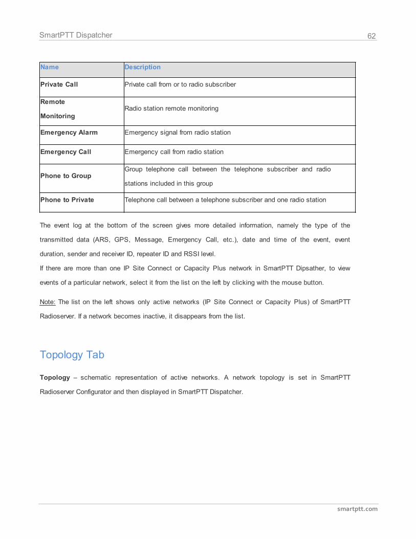
Private Call Private call from or to radio subscriber
Remote
MonitoringRadio station remote monitoring
Emergency Alarm Emergency signal from radio station
Emergency Call Emergency call from radio station
Phone to GroupGroup telephone call between the telephone subscriber and radio
stations included in this group
Phone to Private Telephone call between a telephone subscriber and one radio station
The event log at the bottom of the screen gives more detailed information, namely the type of the
transmitted data (ARS, GPS, Message, Emergency Call, etc.), date and time of the event, event
duration, sender and receiver ID, repeater ID and RSSI level.
If there are more than one IP Site Connect or Capacity Plus network in SmartPTT Dipsather, to view
events of a particular network, select it from the list on the left by clicking with the mouse button.
Note: The list on the left shows only active networks (IP Site Connect or Capacity Plus) of SmartPTT
Radioserver. If a network becomes inactive, it disappears from the list.
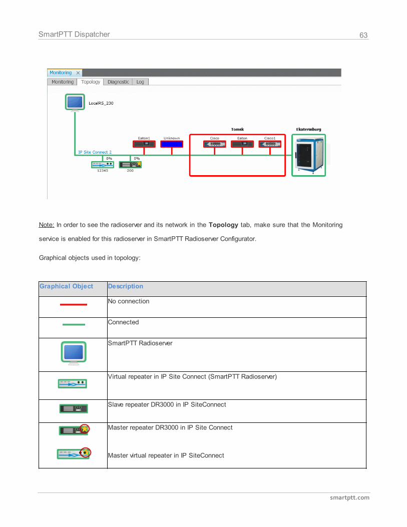
Topology Tab
Topology – schematic representation of active networks. A network topology is set in SmartPTT
Radioserver Configurator and then displayed in SmartPTT Dispatcher.
63
smartptt.com
SmartPTT Dispatcher
Note: In order to see the radioserver and its network in the Topology tab, make sure that the Monitoring
service is enabled for this radioserver in SmartPTT Radioserver Configurator.
Graphical objects used in topology:
Graphical Object Description
No connection
Connected
SmartPTT Radioserver
Virtual repeater in IP Site Connect (SmartPTT Radioserver)
Slave repeater DR3000 in IP SiteConnect
Master repeater DR3000 in IP Site Connect
Master virtual repeater in IP SiteConnect
64
smartptt.com
SmartPTT Dispatcher
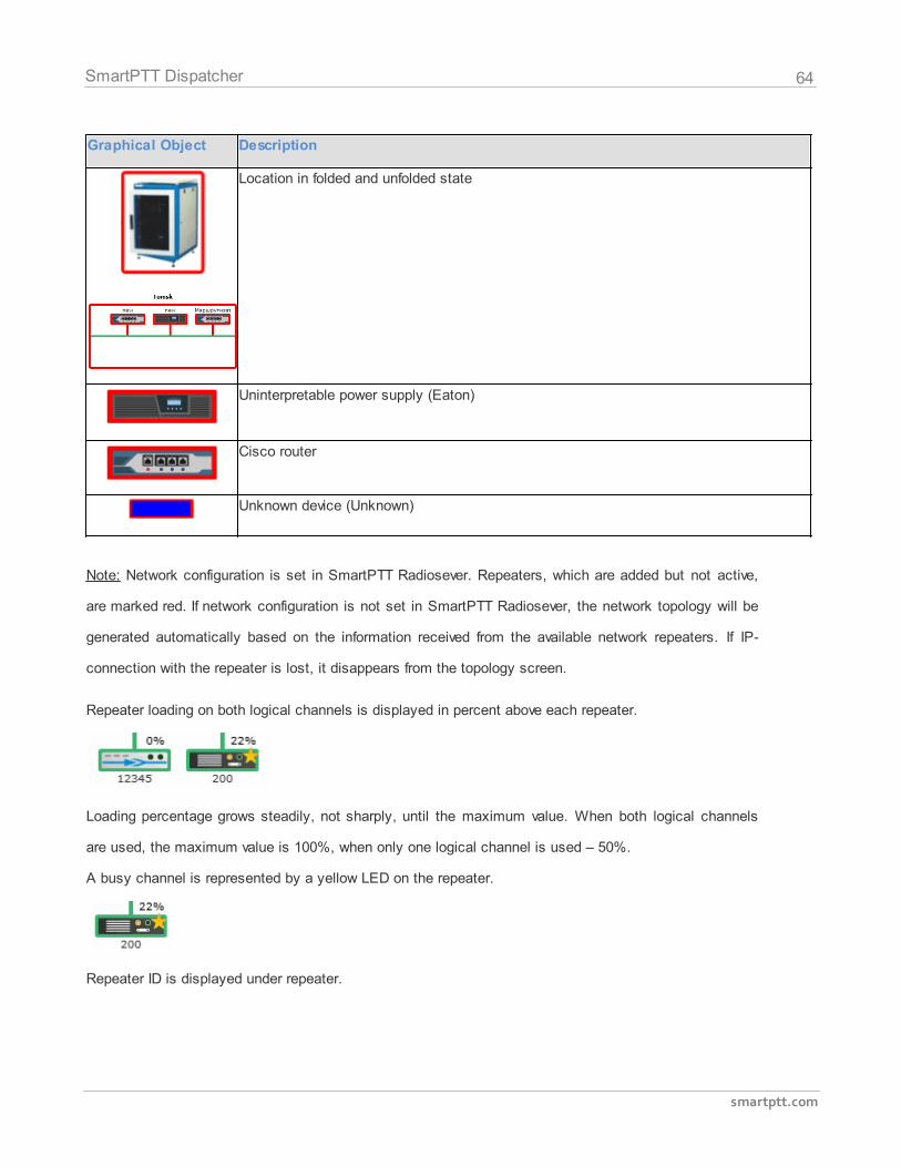
Graphical Object Description
Location in folded and unfolded state
Uninterpretable power supply (Eaton)
Cisco router
Unknown device (Unknown)
Note: Network configuration is set in SmartPTT Radiosever. Repeaters, which are added but not active,
are marked red. If network configuration is not set in SmartPTT Radiosever, the network topology will be
generated automatically based on the information received from the available network repeaters. If IP-
connection with the repeater is lost, it disappears from the topology screen.
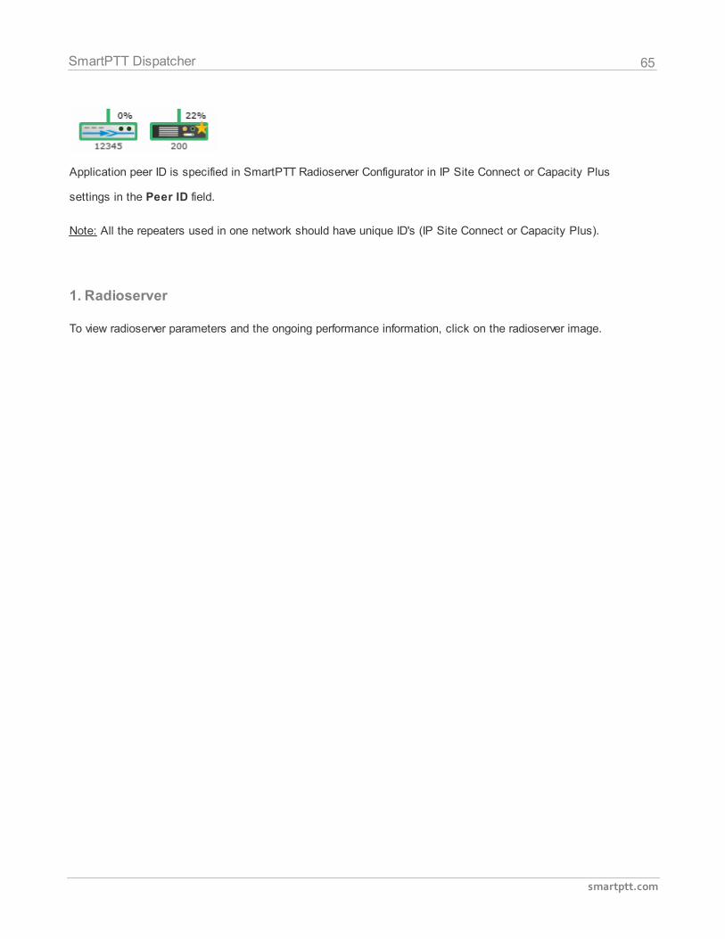
Repeater loading on both logical channels is displayed in percent above each repeater.
Loading percentage grows steadily, not sharply, until the maximum value. When both logical channels
are used, the maximum value is 100%, when only one logical channel is used – 50%.
A busy channel is represented by a yellow LED on the repeater.
Repeater ID is displayed under repeater.
65
smartptt.com
SmartPTT Dispatcher
Application peer ID is specified in SmartPTT Radioserver Configurator in IP Site Connect or Capacity Plus
settings in the Peer ID field.
Note: All the repeaters used in one network should have unique ID's (IP Site Connect or Capacity Plus).
1. Radioserver
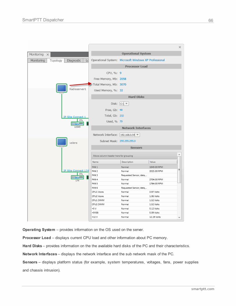
To view radioserver parameters and the ongoing performance information, click on the radioserver image.
66
smartptt.com
SmartPTT Dispatcher
Operating System – provides information on the OS used on the server.
Processor Load – displays current CPU load and other information about PC memory.
Hard Disks – provides information on the the available hard disks of the PC and their characteristics.
Network Interfaces – displays the network interface and the sub network mask of the PC.
Sensors – displays platform status (for example, system temperatures, voltages, fans, power supplies
and chassis intrusion).
67
smartptt.com
SmartPTT Dispatcher
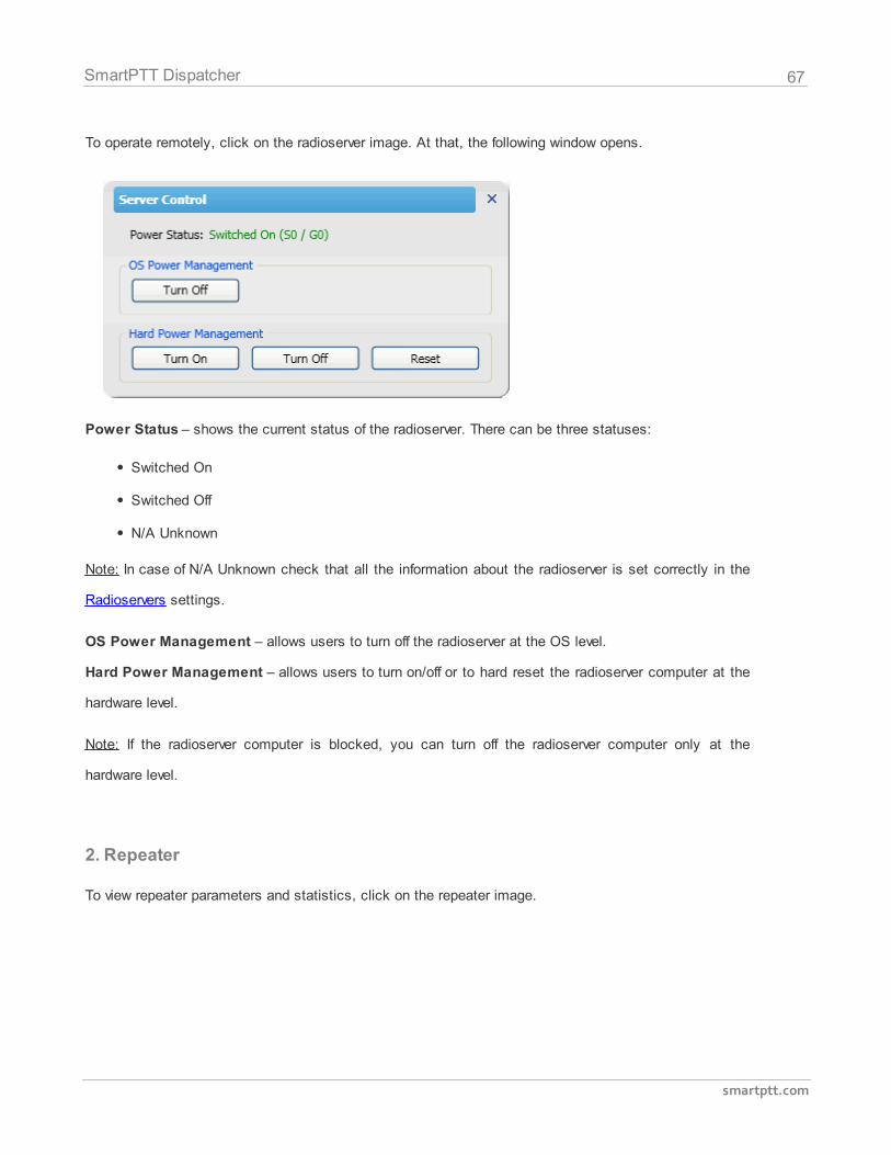
To operate remotely, click on the radioserver image. At that, the following window opens.
Power Status – shows the current status of the radioserver. There can be three statuses:
Switched On
Switched Off
N/A Unknown
Note: In case of N/A Unknown check that all the information about the radioserver is set correctly in the
Radioservers settings.
OS Power Management – allows users to turn off the radioserver at the OS level.
Hard Power Management – allows users to turn on/off or to hard reset the radioserver computer at the
hardware level.
Note: If the radioserver computer is blocked, you can turn off the radioserver computer only at the
hardware level.
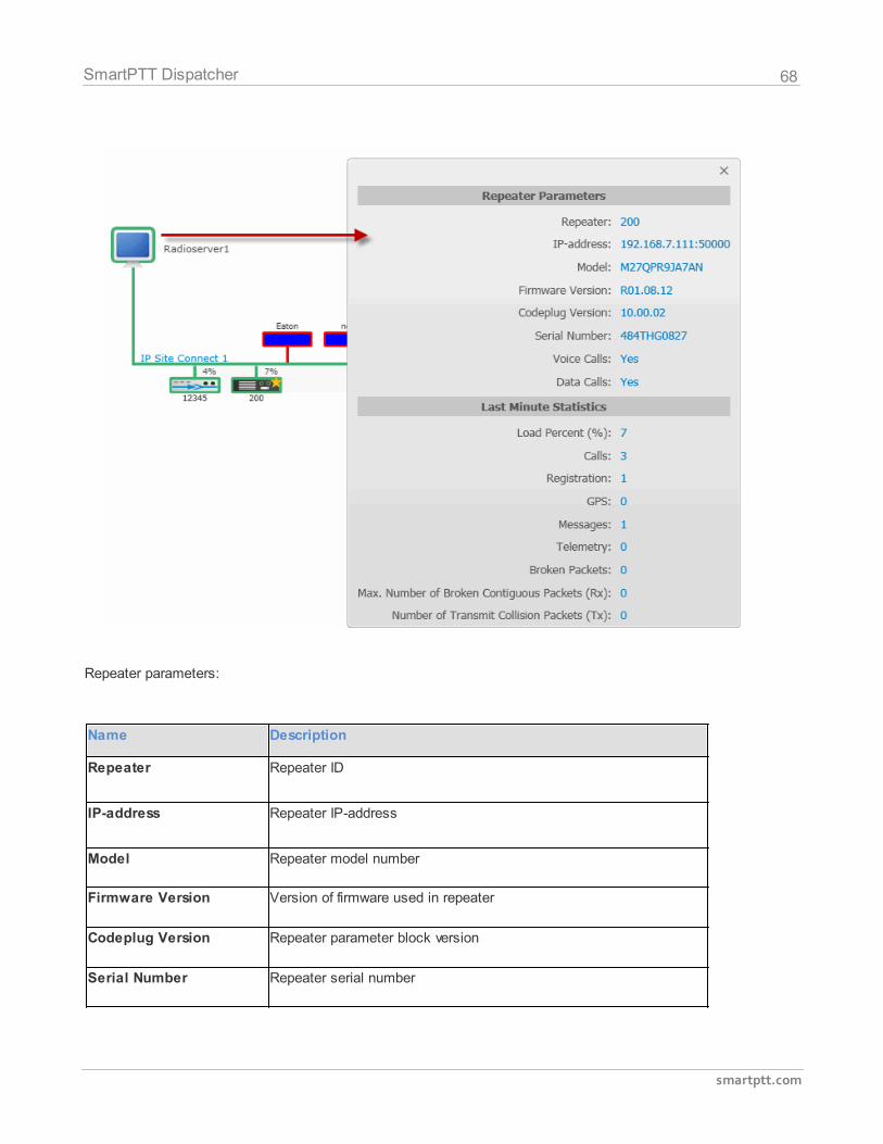
2. Repeater
To view repeater parameters and statistics, click on the repeater image.
68
smartptt.com
SmartPTT Dispatcher
Repeater parameters:
Name Description
Repeater Repeater ID
IP-address Repeater IP-address
Model Repeater model number
Firmware Version Version of firmware used in repeater
Codeplug Version Repeater parameter block version
Serial Number Repeater serial number
69
smartptt.com
SmartPTT Dispatcher
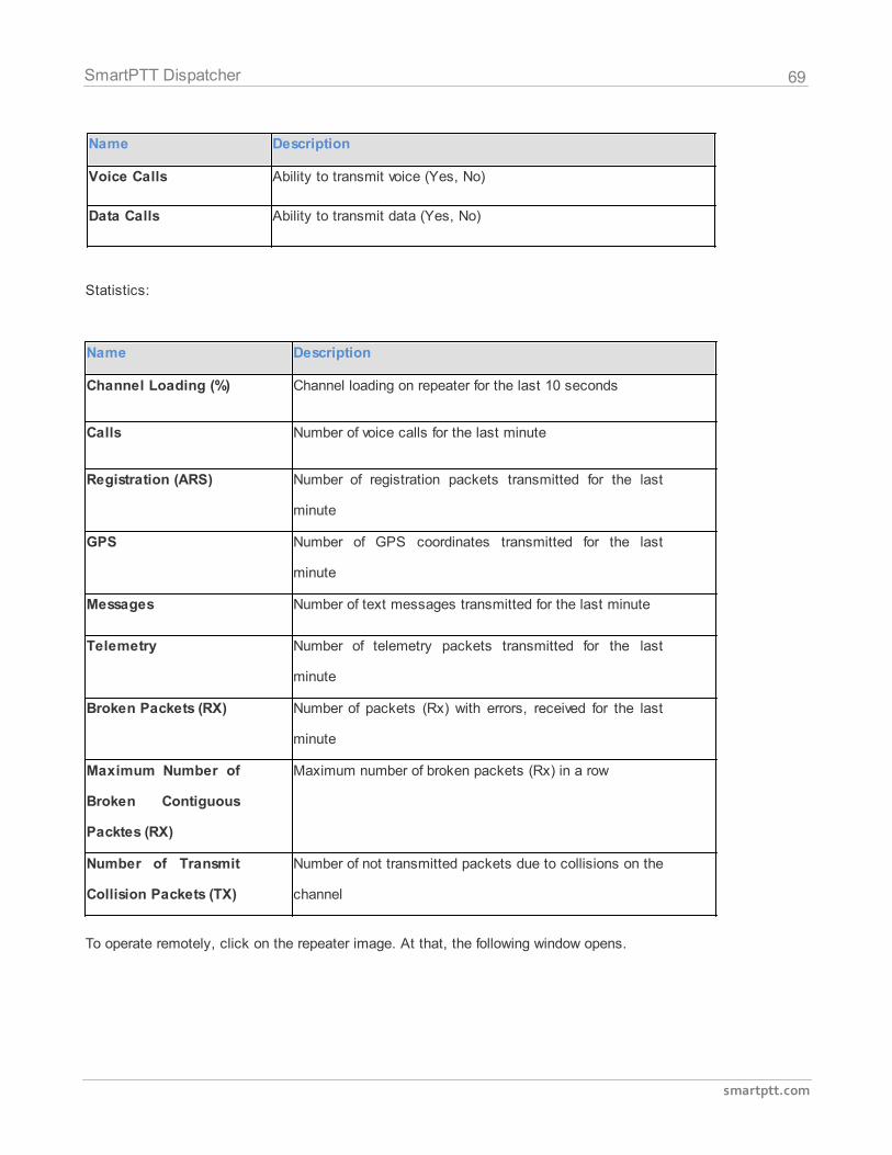
Name Description
Voice Calls Ability to transmit voice (Yes, No)
Data Calls Ability to transmit data (Yes, No)
Statistics:
Name Description
Channel Loading (%) Channel loading on repeater for the last 10 seconds
Calls Number of voice calls for the last minute
Registration (ARS) Number of registration packets transmitted for the last
minute
GPS Number of GPS coordinates transmitted for the last
minute
Messages Number of text messages transmitted for the last minute
Telemetry Number of telemetry packets transmitted for the last
minute
Broken Packets (RX) Number of packets (Rx) with errors, received for the last
minute
Maximum Number of
Broken Contiguous
Packtes (RX)
Maximum number of broken packets (Rx) in a row
Number of Transmit
Collision Packets (TX)
Number of not transmitted packets due to collisions on the
channel
To operate remotely, click on the repeater image. At that, the following window opens.
70
smartptt.com
SmartPTT Dispatcher
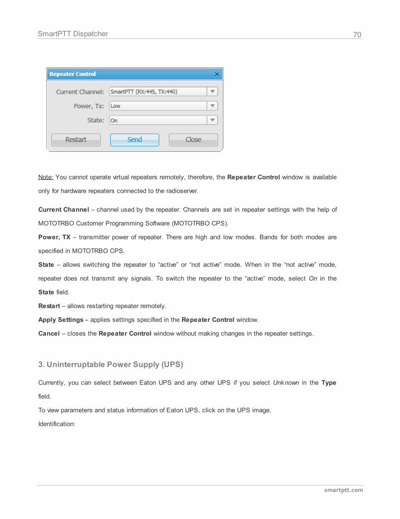
Note: You cannot operate virtual repeaters remotely, therefore, the Repeater Control window is available
only for hardware repeaters connected to the radioserver.
Current Channel – channel used by the repeater. Channels are set in repeater settings with the help of
MOTOTRBO Customer Programming Software (MOTOTRBO CPS).
Power, TX – transmitter power of repeater. There are high and low modes. Bands for both modes are
specified in MOTOTRBO CPS.
State – allows switching the repeater to “active” or “not active” mode. When in the “not active” mode,
repeater does not transmit any signals. To switch the repeater to the “active” mode, select On in the
State field.
Restart – allows restarting repeater remotely.
Apply Settings – applies settings specified in the Repeater Control window.
Cancel – closes the Repeater Control window without making changes in the repeater settings.
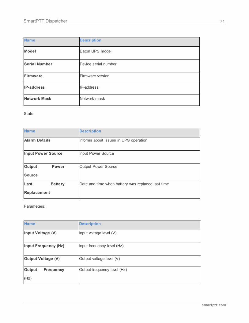
3. Uninterruptable Power Supply (UPS)
Currently, you can select between Eaton UPS and any other UPS if you select Unknown in the Type
field.
To view parameters and status information of Eaton UPS, click on the UPS image.
Identification:
71
smartptt.com
SmartPTT Dispatcher
Name Description
Model Eaton UPS model
Serial Number Device serial number
Firmware Firmware version
IP-address IP-address
Network Mask Network mask
State:
Name Description
Alarm Details Informs about issues in UPS operation
Input Power Source Input Power Source
Output Power
Source
Output Power Source
Last Battery
Replacement
Date and time when battery was replaced last time
Parameters:
Name Description
Input Voltage (V) Input voltage level (V)
Input Frequency (Hz) Input frequency level (Hz)
Output Voltage (V) Output voltage level (V)
Output Frequency
(Hz)
Output frequency level (Hz)
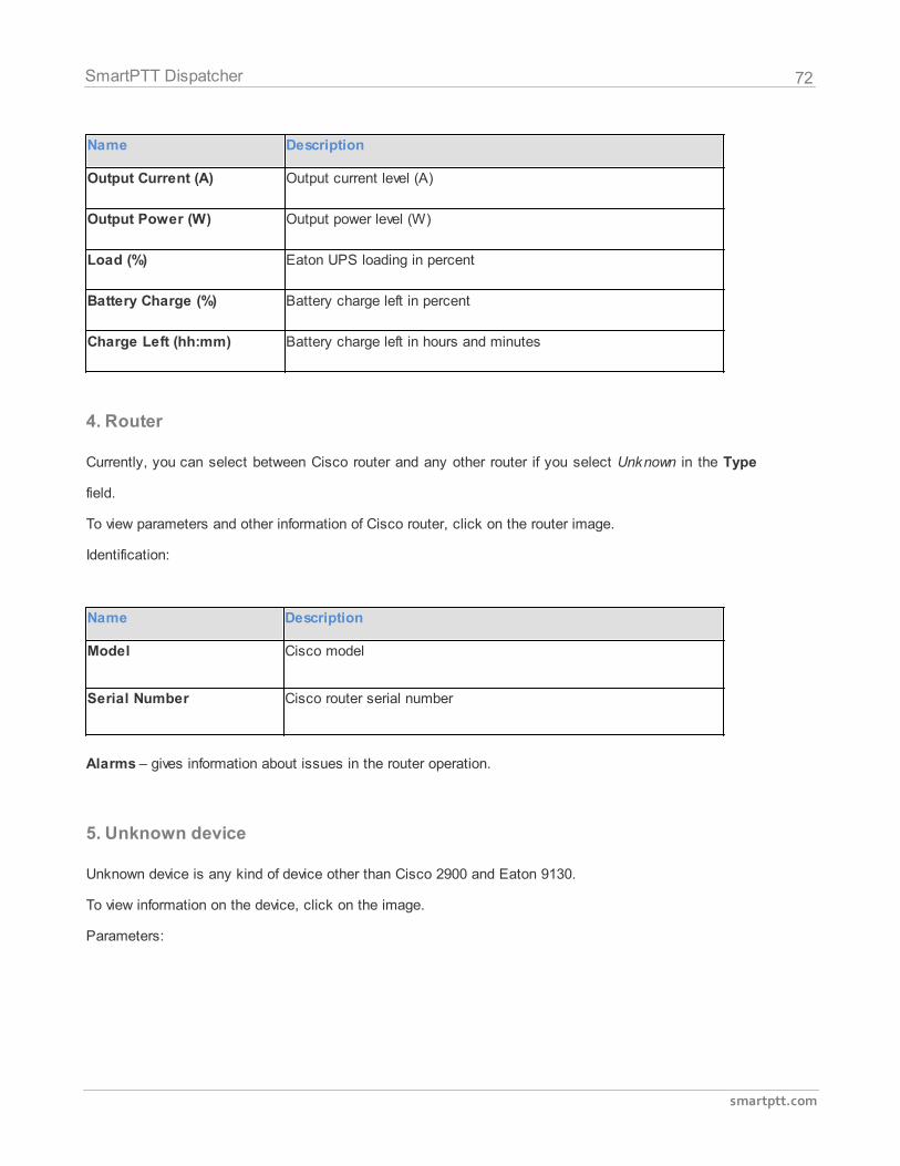
72
smartptt.com
SmartPTT Dispatcher
Name Description
Output Current (A) Output current level (A)
Output Power (W) Output power level (W)
Load (%) Eaton UPS loading in percent
Battery Charge (%) Battery charge left in percent
Charge Left (hh:mm) Battery charge left in hours and minutes
4. Router
Currently, you can select between Cisco router and any other router if you select Unknown in the Type
field.
To view parameters and other information of Cisco router, click on the router image.
Identification:
Name Description
Model Cisco model
Serial Number Cisco router serial number
Alarms – gives information about issues in the router operation.
5. Unknown device
Unknown device is any kind of device other than Cisco 2900 and Eaton 9130.
To view information on the device, click on the image.
Parameters:
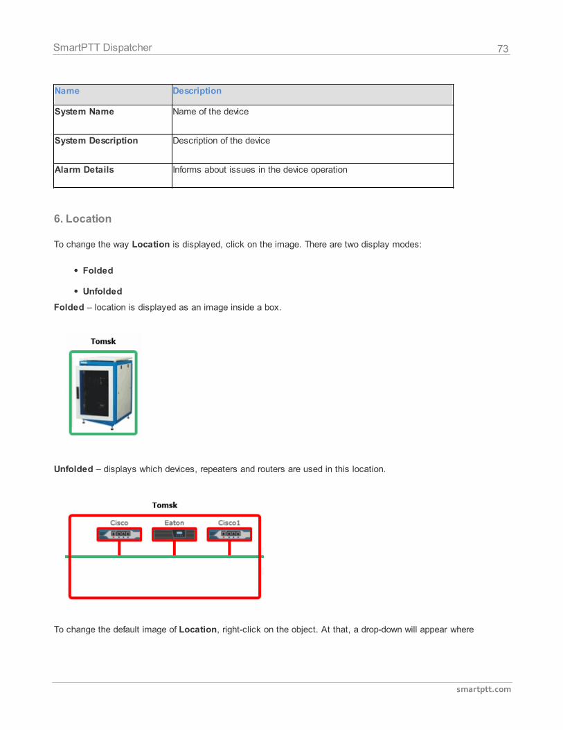
73
smartptt.com
SmartPTT Dispatcher
Name Description
System Name Name of the device
System Description Description of the device
Alarm Details Informs about issues in the device operation
6. Location
To change the way Location is displayed, click on the image. There are two display modes:
Folded
Unfolded
Folded – location is displayed as an image inside a box.
Unfolded – displays which devices, repeaters and routers are used in this location.
To change the default image of Location, right-click on the object. At that, a drop-down will appear where
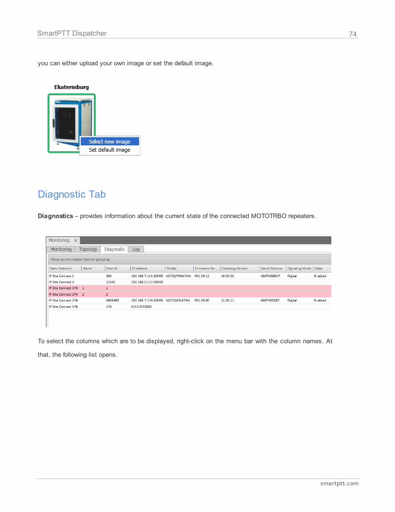
74
smartptt.com
SmartPTT Dispatcher
you can either upload your own image or set the default image.
Diagnostic Tab
Diagnostics – provides information about the current state of the connected MOTOTRBO repeaters.
To select the columns which are to be displayed, right-click on the menu bar with the column names. At
that, the following list opens.
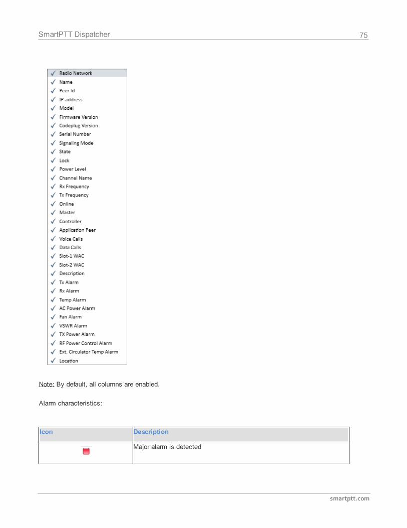
75
smartptt.com
SmartPTT Dispatcher
Note: By default, all columns are enabled.
Alarm characteristics:
Icon Description
Major alarm is detected
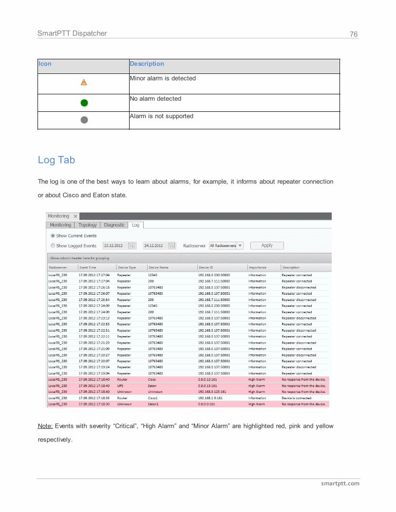
76
smartptt.com
SmartPTT Dispatcher
Icon Description
Minor alarm is detected
No alarm detected
Alarm is not supported
Log Tab
The log is one of the best ways to learn about alarms, for example, it informs about repeater connection
or about Cisco and Eaton state.
Note: Events with severity “Critical”, “High Alarm” and “Minor Alarm” are highlighted red, pink and yellow
respectively.
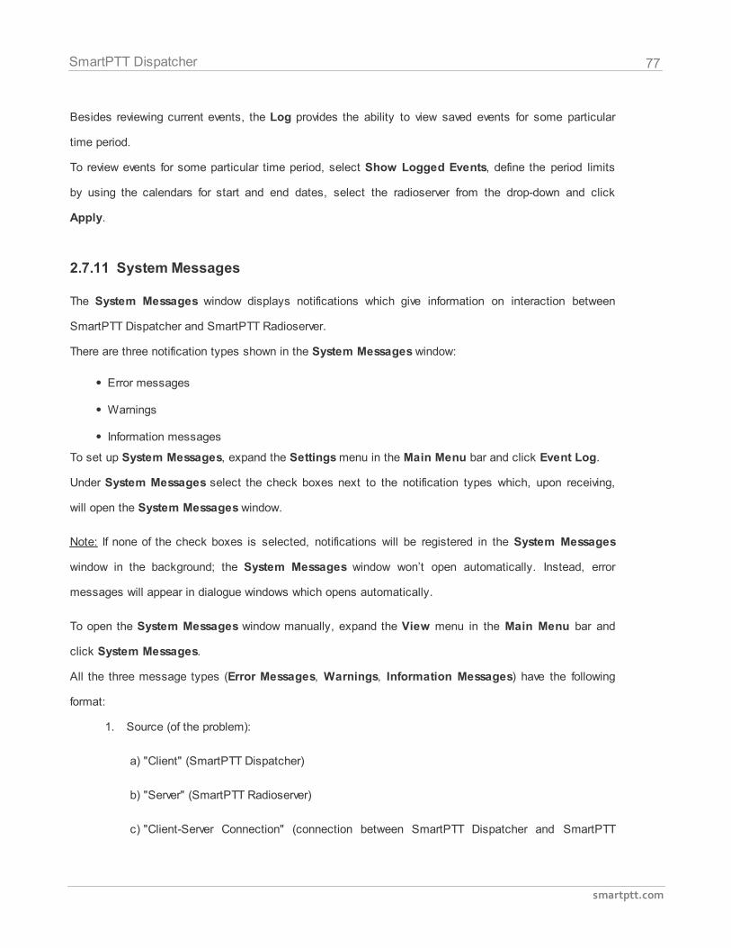
77
smartptt.com
SmartPTT Dispatcher
Besides reviewing current events, the Log provides the ability to view saved events for some particular
time period.
To review events for some particular time period, select Show Logged Events, define the period limits
by using the calendars for start and end dates, select the radioserver from the drop-down and click
Apply.
2.7.11 System Messages
The System Messages window displays notifications which give information on interaction between
SmartPTT Dispatcher and SmartPTT Radioserver.
There are three notification types shown in the System Messages window:
Error messages
Warnings
Information messages
To set up System Messages, expand the Settings menu in the Main Menu bar and click Event Log.
Under System Messages select the check boxes next to the notification types which, upon receiving,
will open the System Messages window.
Note: If none of the check boxes is selected, notifications will be registered in the System Messages
window in the background; the System Messages window won’t open automatically. Instead, error
messages will appear in dialogue windows which opens automatically.
To open the System Messages window manually, expand the View menu in the Main Menu bar and
click System Messages.
All the three message types (Error Messages, Warnings, Information Messages) have the following
format:
1. Source (of the problem):
a) "Client" (SmartPTT Dispatcher)
b) "Server" (SmartPTT Radioserver)
c) "Client-Server Connection" (connection between SmartPTT Dispatcher and SmartPTT
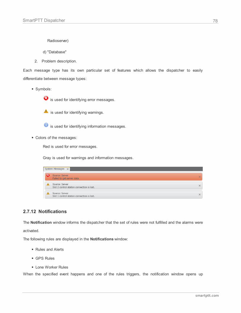
78
smartptt.com
SmartPTT Dispatcher
Radioserver)
d) "Database"
2. Problem description.
Each message type has its own particular set of features which allows the dispatcher to easily
differentiate between message types:
Symbols:
is used for identifying error messages.
is used for identifying warnings.
is used for identifying information messages.
Colors of the messages:
Red is used for error messages.
Gray is used for warnings and information messages.
2.7.12 Notifications
The Notification window informs the dispatcher that the set of rules were not fulfilled and the alarms were
activated.
The following rules are displayed in the Notifications window:
Rules and Alerts
GPS Rules
Lone Worker Rules
When the specified event happens and one of the rules triggers, the notification window opens up
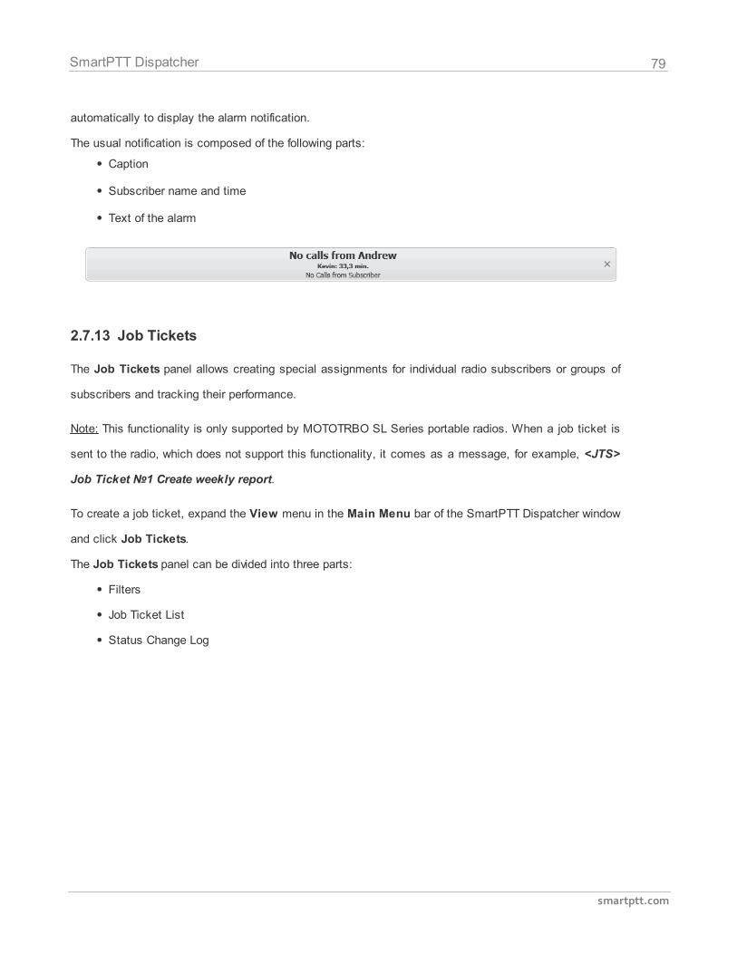
79
smartptt.com
SmartPTT Dispatcher
automatically to display the alarm notification.
The usual notification is composed of the following parts:
Caption
Subscriber name and time
Text of the alarm
2.7.13 Job Tickets
The Job Tickets panel allows creating special assignments for individual radio subscribers or groups of
subscribers and tracking their performance.
Note: This functionality is only supported by MOTOTRBO SL Series portable radios. When a job ticket is
sent to the radio, which does not support this functionality, it comes as a message, for example, <JTS>
Job Ticket Create weekly report.
To create a job ticket, expand the View menu in the Main Menu bar of the SmartPTT Dispatcher window
and click Job Tickets.
The Job Tickets panel can be divided into three parts:
Filters
Job Ticket List
Status Change Log
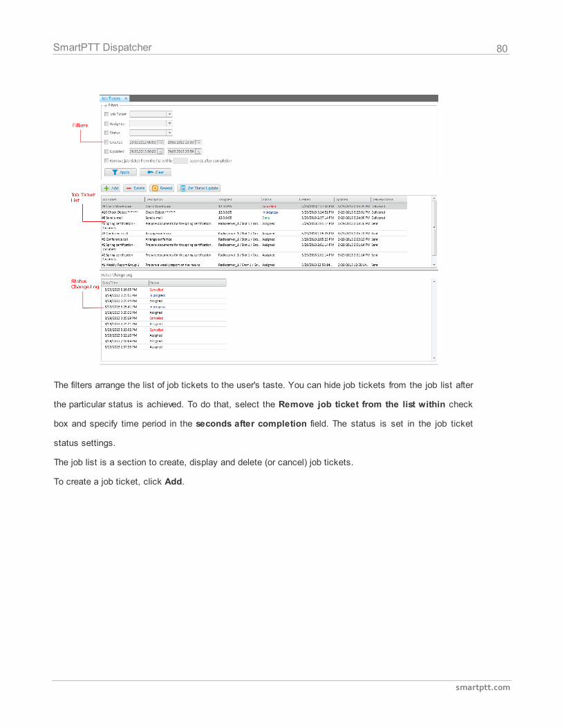
80
smartptt.com
SmartPTT Dispatcher
The filters arrange the list of job tickets to the user's taste. You can hide job tickets from the job list after
the particular status is achieved. To do that, select the Remove job ticket from the list within check
box and specify time period in the seconds after completion field. The status is set in the job ticket
status settings.
The job list is a section to create, display and delete (or cancel) job tickets.
To create a job ticket, click Add.
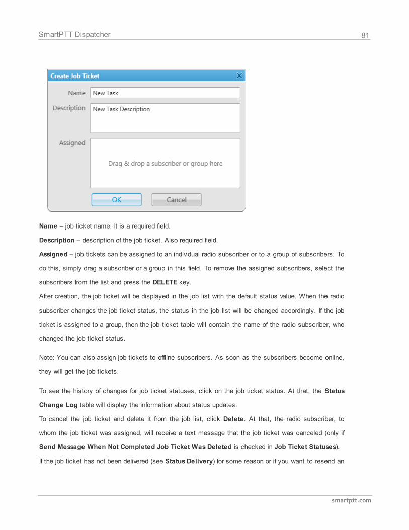
81
smartptt.com
SmartPTT Dispatcher
Name – job ticket name. It is a required field.
Description – description of the job ticket. Also required field.
Assigned – job tickets can be assigned to an individual radio subscriber or to a group of subscribers. To
do this, simply drag a subscriber or a group in this field. To remove the assigned subscribers, select the
subscribers from the list and press the DELETE key.
After creation, the job ticket will be displayed in the job list with the default status value. When the radio
subscriber changes the job ticket status, the status in the job list will be changed accordingly. If the job
ticket is assigned to a group, then the job ticket table will contain the name of the radio subscriber, who
changed the job ticket status.
Note: You can also assign job tickets to offline subscribers. As soon as the subscribers become online,
they will get the job tickets.
To see the history of changes for job ticket statuses, click on the job ticket status. At that, the Status
Change Log table will display the information about status updates.
To cancel the job ticket and delete it from the job list, click Delete. At that, the radio subscriber, to
whom the job ticket was assigned, will receive a text message that the job ticket was canceled (only if
Send Message When Not Completed Job Ticket Was Deleted is checked in Job Ticket Statuses).
If the job ticket has not been delivered (see Status Delivery) for some reason or if you want to resend an
82
smartptt.com
SmartPTT Dispatcher
existing job ticket to the radio subscriber or a group of subscribers, click Resend. In this case, the job
ticket will change its status to the default value.
Information about job ticket statuses can be obtained even for the period, when the dispatcher console
was turned off. To do this, click Get Update Status to load data from the radioserver database.
2.8 Settings
The Settings menu allows you to configure the basic parameters of the system, create special rules,
which will help you manage your workers, connect external third-party devices and so on. From the
Settings menu you can:
Manage the database of the system.
Install licenses.
enable automated system updating, select the language of the dispatcher console.
Manage available radioservers.
Add statuses for radio subscribers, displayed in the Subscribers Management panel.
Manage the Event Log and the System Messages.
Configure Call Windows parameters.
Configure sound settings.
Manage recording.
Configure GPS settings.
Create raster maps.
Configure telemetry settings.
Manage categories.
Add other dispatchers and configure your own dispatcher.
Configure telephone settings and add telephone subscribers.
Add status for job ticketing.
Configure Tipro settings.
Define rules conditions.
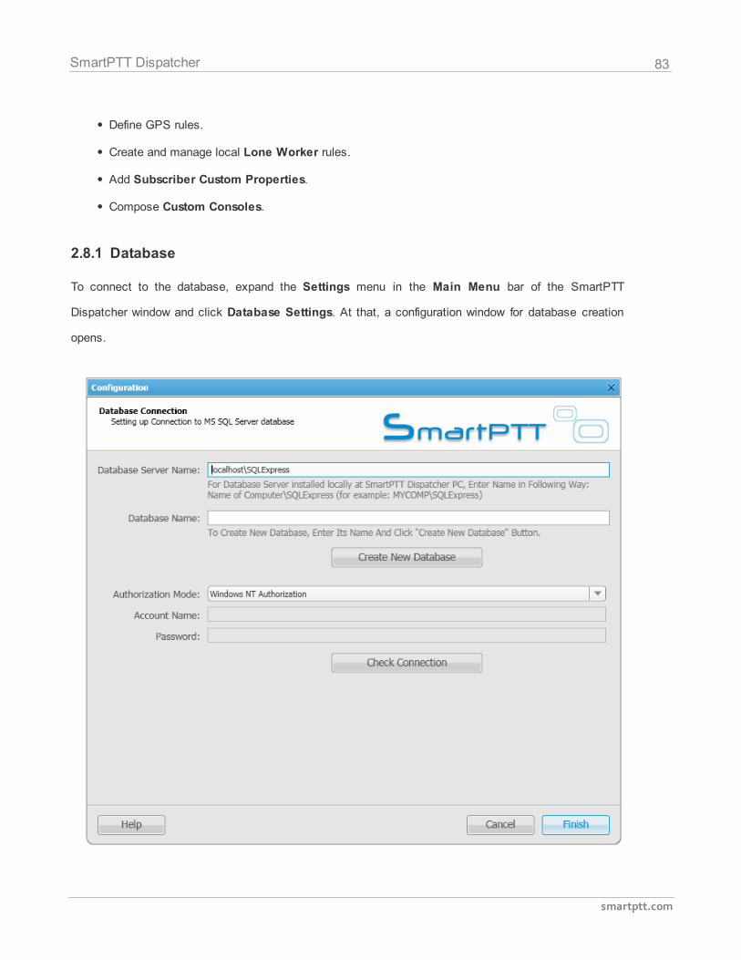
83
smartptt.com
SmartPTT Dispatcher
Define GPS rules.
Create and manage local Lone Worker rules.
Add Subscriber Custom Properties.
Compose Custom Consoles.
2.8.1 Database
To connect to the database, expand the Settings menu in the Main Menu bar of the SmartPTT
Dispatcher window and click Database Settings. At that, a configuration window for database creation
opens.
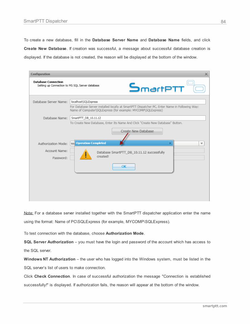
84
smartptt.com
SmartPTT Dispatcher
To create a new database, fill in the Database Server Name and Database Name fields, and click
Create New Database. If creation was successful, a message about successful database creation is
displayed. If the database is not created, the reason will be displayed at the bottom of the window.
Note: For a database server installed together with the SmartPTT dispatcher application enter the name
using the format: Name of PC\SQLExpress (for example, MYCOMP\SQLExpress).
To test connection with the database, choose Authorization Mode.
SQL Server Authorization – you must have the login and password of the account which has access to
the SQL server.
Windows NT Authorization – the user who has logged into the Windows system, must be listed in the
SQL server’s list of users to make connection.
Click Check Connection. In case of successful authorization the message "Connection is established
successfully!" is displayed. If authorization fails, the reason will appear at the bottom of the window.
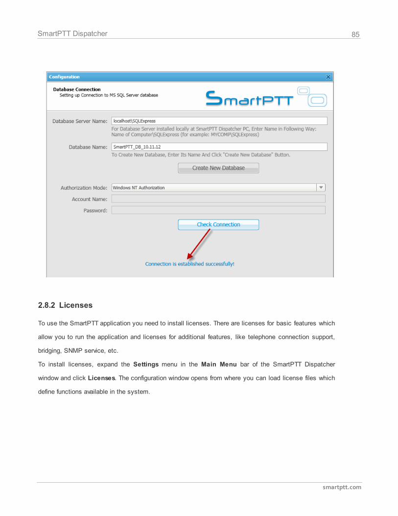
85
smartptt.com
SmartPTT Dispatcher
2.8.2 Licenses
To use the SmartPTT application you need to install licenses. There are licenses for basic features which
allow you to run the application and licenses for additional features, like telephone connection support,
bridging, SNMP service, etc.
To install licenses, expand the Settings menu in the Main Menu bar of the SmartPTT Dispatcher
window and click Licenses. The configuration window opens from where you can load license files which
define functions available in the system.
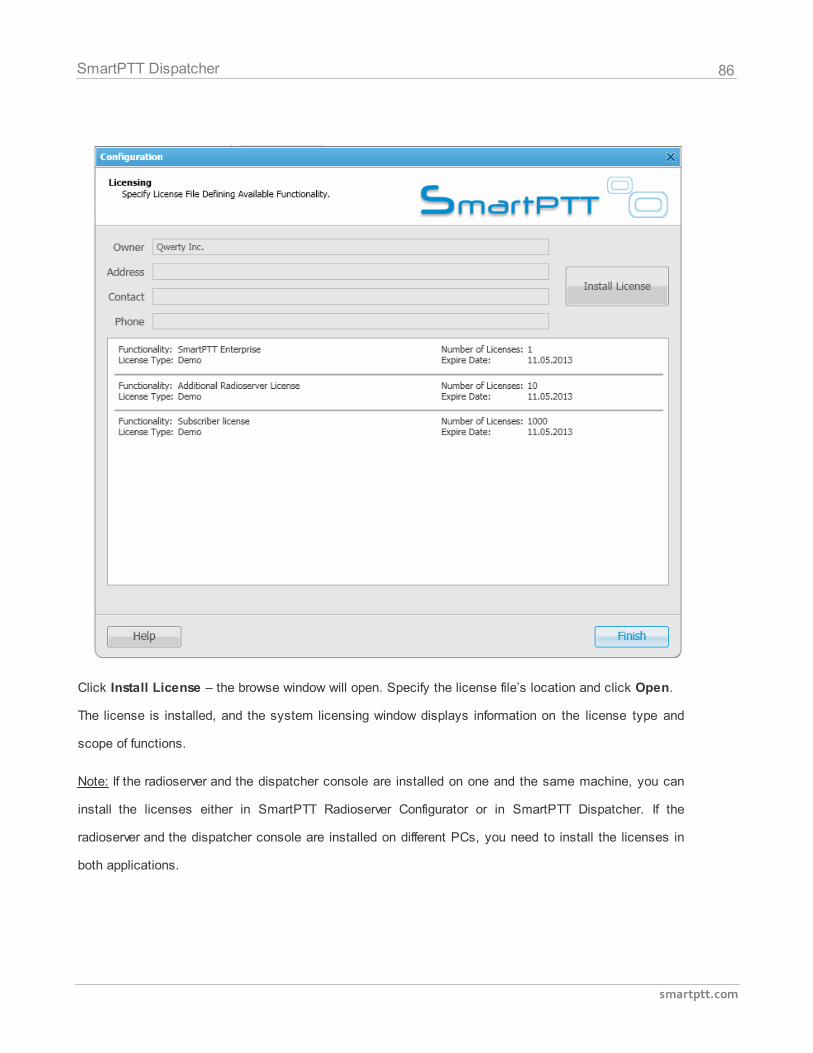
86
smartptt.com
SmartPTT Dispatcher
Click Install License – the browse window will open. Specify the license file’s location and click Open.
The license is installed, and the system licensing window displays information on the license type and
scope of functions.
Note: If the radioserver and the dispatcher console are installed on one and the same machine, you can
install the licenses either in SmartPTT Radioserver Configurator or in SmartPTT Dispatcher. If the
radioserver and the dispatcher console are installed on different PCs, you need to install the licenses in
both applications.
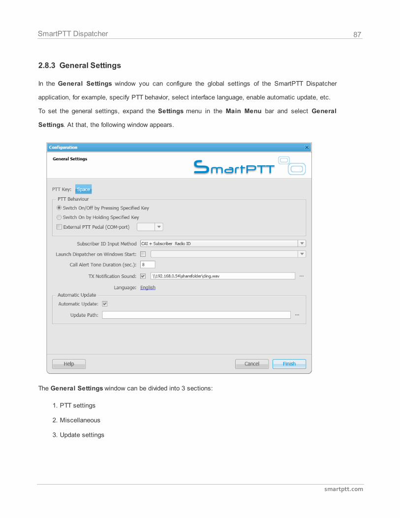
87
smartptt.com
SmartPTT Dispatcher
2.8.3 General Settings
In the General Settings window you can configure the global settings of the SmartPTT Dispatcher
application, for example, specify PTT behavior, select interface language, enable automatic update, etc.
To set the general settings, expand the Settings menu in the Main Menu bar and select General
Settings. At that, the following window appears.
The General Settings window can be divided into 3 sections:
1. PTT settings
2. Miscellaneous
3. Update settings
88
smartptt.com
SmartPTT Dispatcher
1. PTT Settings
PTT Key allows you to set up any key of the keyboard as the PTT button. To do it, click on the selected
key and then press any key on the keyboard. To save the change, click Finish.
Switch On/Off by Pressing Specified Key, Switch On by Holding Specified Key – options which
define how PTT is enabled/disabled.
External PTT Pedal (COM-port) – COM-port used for connection of external PTT pedal.
2. Miscellaneous
Subscriber ID Input Method sets the input and display method used for showing network ID in the radio
subscriber Properties window: IP address or CAI + subscriber ID.
IP Address – IP address is entered and displayed in the subscriber Properties window, for example,
.
CAI + Subscriber ID (CAI network ID and a unique radio station ID) are entered and displayed in the
subscriber's Properties window, for example, .
Launch Dispatcher on Windows Start – launches SmartPTT Dispatcher automatically on Windows
start under specified dispatcher account.
Call Alert Tone Duration (sec.) – configures the call alert tone sound duration for the Dispatcher
application.
Talk Permit Tone – sets alert tone which sounds after the PTT button is pressed and the dispatcher is
able to transmit on the channel.
Confirm Before Closing – if selected, the application will ask for a confirmation before closing.
Language – selects interface language.
Note: After selecting a new language, restart SmartPTT Dispatcher to apply the change.
3. Update settings
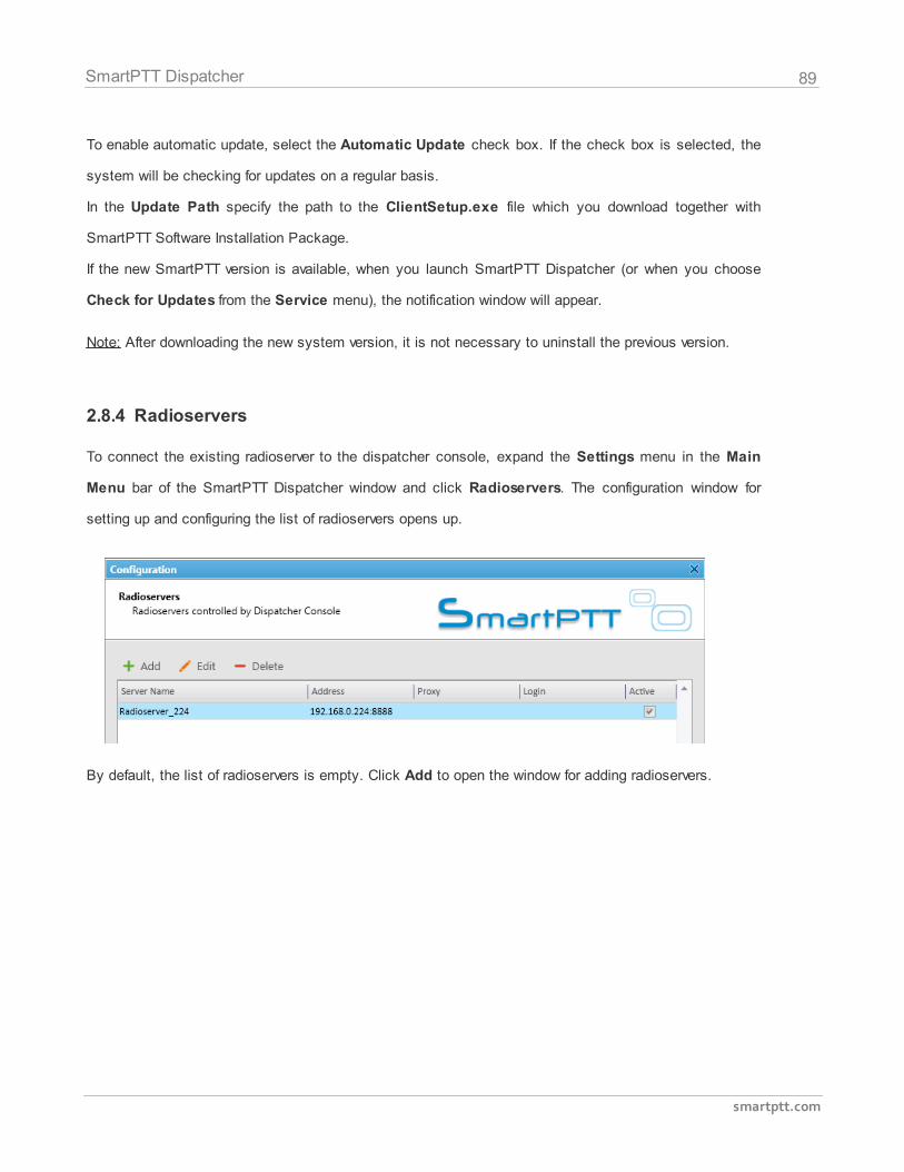
89
smartptt.com
SmartPTT Dispatcher
To enable automatic update, select the Automatic Update check box. If the check box is selected, the
system will be checking for updates on a regular basis.
In the Update Path specify the path to the ClientSetup.exe file which you download together with
SmartPTT Software Installation Package.
If the new SmartPTT version is available, when you launch SmartPTT Dispatcher (or when you choose
Check for Updates from the Service menu), the notification window will appear.
Note: After downloading the new system version, it is not necessary to uninstall the previous version.
2.8.4 Radioservers
To connect the existing radioserver to the dispatcher console, expand the Settings menu in the Main
Menu bar of the SmartPTT Dispatcher window and click Radioservers. The configuration window for
setting up and configuring the list of radioservers opens up.
By default, the list of radioservers is empty. Click Add to open the window for adding radioservers.
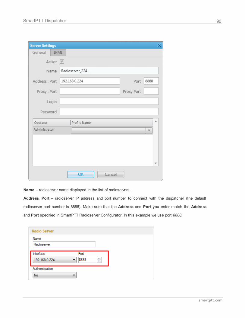
90
smartptt.com
SmartPTT Dispatcher
Name – radioserver name displayed in the list of radioservers.
Address, Port – radioserver IP address and port number to connect with the dispatcher (the default
radioserver port number is 8888). Make sure that the Address and Port you enter match the Address
and Port specified in SmartPTT Radioserver Configurator. In this example we use port 8888.
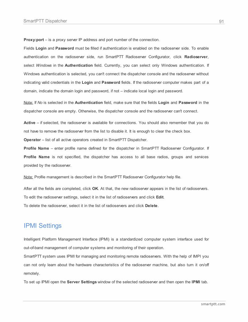
91
smartptt.com
SmartPTT Dispatcher
Proxy:port – is a proxy server IP address and port number of the connection.
Fields Login and Password must be filled if authentication is enabled on the radioserver side. To enable
authentication on the radioserver side, run SmartPTT Radioserver Configurator, click Radioserver,
select Windows in the Authentication field. Currently, you can select only Windows authentication. If
Windows authentication is selected, you can't connect the dispatcher console and the radioserver without
indicating valid credentials in the Login and Password fields. If the radioserver computer makes part of a
domain, indicate the domain login and password, if not – indicate local login and password.
Note: If No is selected in the Authentication field, make sure that the fields Login and Password in the
dispatcher console are empty. Otherwise, the dispatcher console and the radioserver can't connect.
Active – if selected, the radioserver is available for connections. You should also remember that you do
not have to remove the radioserver from the list to disable it. It is enough to clear the check box.
Operator – list of all active operators created in SmartPTT Dispatcher.
Profile Name – enter profile name defined for the dispatcher in SmartPTT Radioserver Configurator. If
Profile Name is not specified, the dispatcher has access to all base radios, groups and services
provided by the radioserver.
Note: Profile management is described in the SmartPTT Radioserver Configurator help file.
After all the fields are completed, click OK. At that, the new radioserver appears in the list of radioservers.
To edit the radioserver settings, select it in the list of radioservers and click Edit.
To delete the radioserver, select it in the list of radioservers and click Delete.
IPMI Settings
Intelligent Platform Management Interface (IPMI) is a standardized computer system interface used for
out-of-band management of computer systems and monitoring of their operation.
SmartPTT system uses IPMI for managing and monitoring remote radioservers. With the help of IMPI you
can not only learn about the hardware characteristics of the radioserver machine, but also turn it on/off
remotely.
To set up IPMI open the Server Settings window of the selected radioserver and then open the IPMI tab.
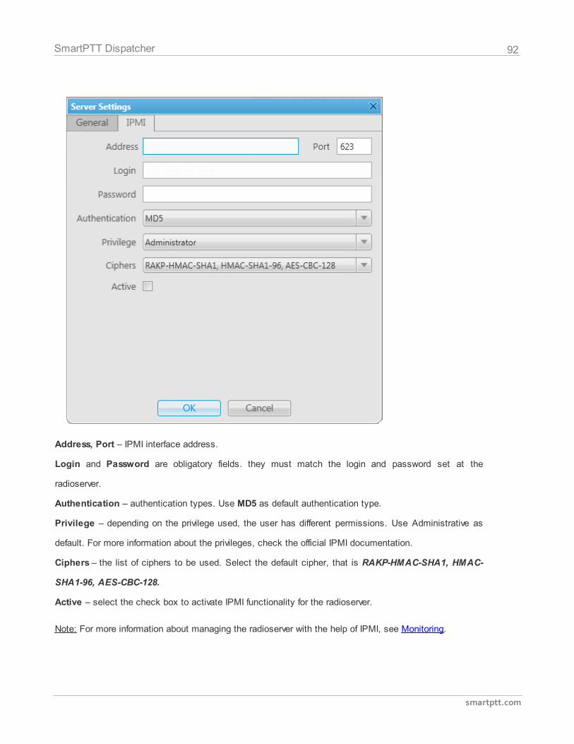
92
smartptt.com
SmartPTT Dispatcher
Address, Port – IPMI interface address.
Login and Password are obligatory fields. they must match the login and password set at the
radioserver.
Authentication – authentication types. Use MD5 as default authentication type.
Privilege – depending on the privilege used, the user has different permissions. Use Administrative as
default. For more information about the privileges, check the official IPMI documentation.
Ciphers – the list of ciphers to be used. Select the default cipher, that is RAKP-HMAC-SHA1, HMAC-
SHA1-96, AES-CBC-128.
Active – select the check box to activate IPMI functionality for the radioserver.
Note: For more information about managing the radioserver with the help of IPMI, see Monitoring.
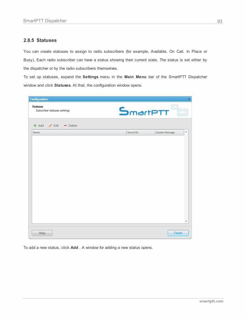
93
smartptt.com
SmartPTT Dispatcher
2.8.5 Statuses
You can create statuses to assign to radio subscribers (for example, Available, On Call, In Place or
Busy). Each radio subscriber can have a status showing their current state. The status is set either by
the dispatcher or by the radio subscribers themselves.
To set up statuses, expand the Settings menu in the Main Menu bar of the SmartPTT Dispatcher
window and click Statuses. At that, the configuration window opens.
To add a new status, click Add . A window for adding a new status opens.
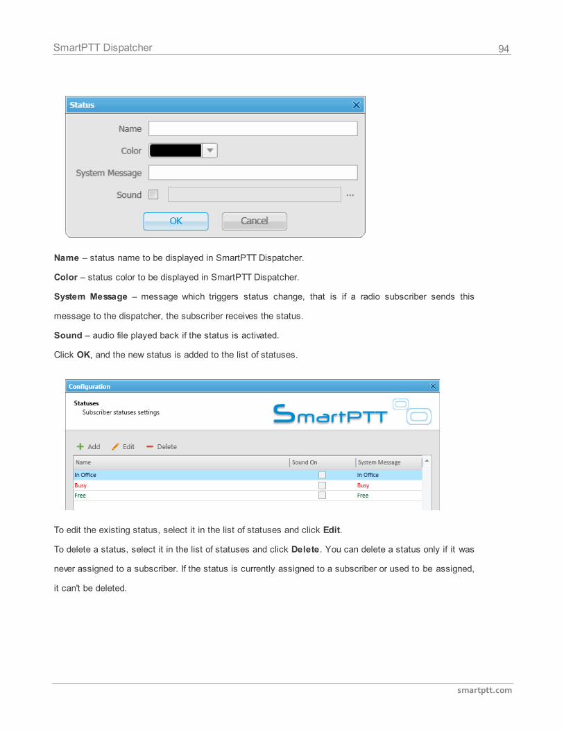
94
smartptt.com
SmartPTT Dispatcher
Name – status name to be displayed in SmartPTT Dispatcher.
Color – status color to be displayed in SmartPTT Dispatcher.
System Message – message which triggers status change, that is if a radio subscriber sends this
message to the dispatcher, the subscriber receives the status.
Sound – audio file played back if the status is activated.
Click OK, and the new status is added to the list of statuses.
To edit the existing status, select it in the list of statuses and click Edit.
To delete a status, select it in the list of statuses and click Delete. You can delete a status only if it was
never assigned to a subscriber. If the status is currently assigned to a subscriber or used to be assigned,
it can't be deleted.
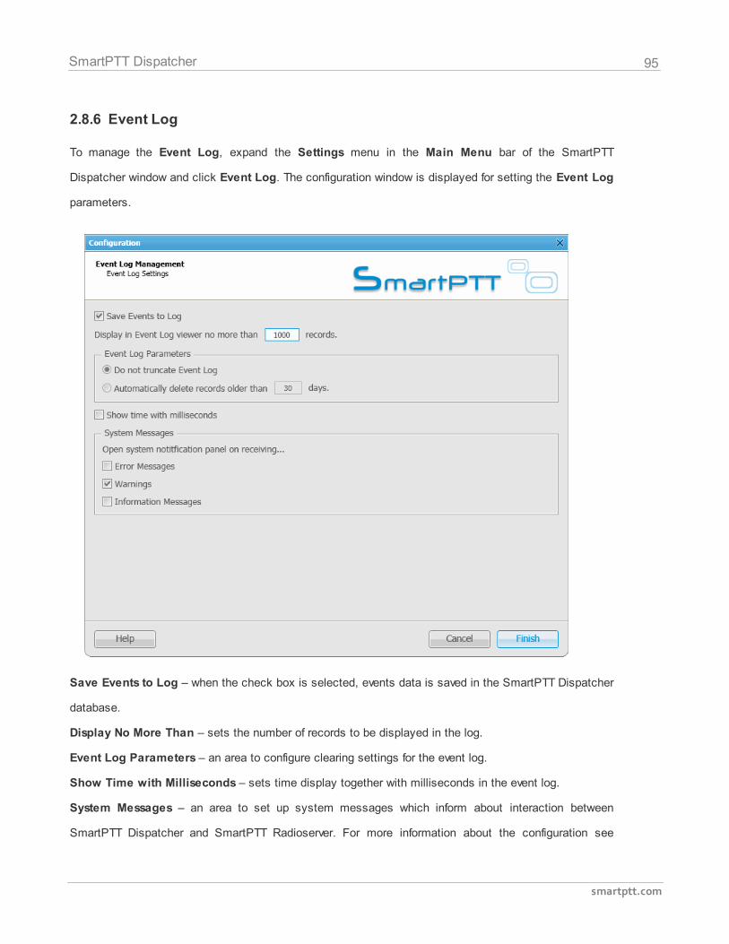
95
smartptt.com
SmartPTT Dispatcher
2.8.6 Event Log
To manage the Event Log, expand the Settings menu in the Main Menu bar of the SmartPTT
Dispatcher window and click Event Log. The configuration window is displayed for setting the Event Log
parameters.
Save Events to Log – when the check box is selected, events data is saved in the SmartPTT Dispatcher
database.
Display No More Than – sets the number of records to be displayed in the log.
Event Log Parameters – an area to configure clearing settings for the event log.
Show Time with Milliseconds – sets time display together with milliseconds in the event log.
System Messages – an area to set up system messages which inform about interaction between
SmartPTT Dispatcher and SmartPTT Radioserver. For more information about the configuration see
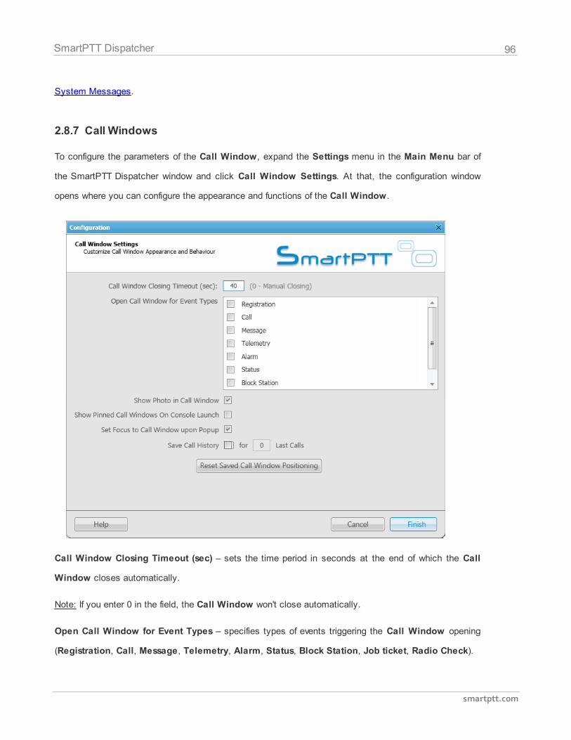
96
smartptt.com
SmartPTT Dispatcher
System Messages.
2.8.7 Call Windows
To configure the parameters of the Call Window, expand the Settings menu in the Main Menu bar of
the SmartPTT Dispatcher window and click Call Window Settings. At that, the configuration window
opens where you can configure the appearance and functions of the Call Window.
Call Window Closing Timeout (sec) – sets the time period in seconds at the end of which the Call
Window closes automatically.
Note: If you enter 0 in the field, the Call Window won't close automatically.
Open Call Window for Event Types – specifies types of events triggering the Call Window opening
(Registration, Call, Message, Telemetry, Alarm, Status, Block Station, Job ticket, Radio Check).
97
smartptt.com
SmartPTT Dispatcher
Show Photo in Call Window – select to display the subscriber's photo in the Call Window.
Show Pinned Call Windows on Console Launch – if selected, the position of the Call Windows,
pinned before the SmartPTT Dispatcher application closing, will be restored during next launch.
Make Call Window Active upon Opening – select the check box to focus on the Call Window when
it is opened or have a new activity.
Save Call History – allows you to keep call history when SmartPTT Dispatcher is closed.
Reset Saved Call Window Positioning – click the button to reset the current position of the call
windows.
2.8.8 Sound
To set audio device settings and VoIP parameters, expand the Settings menu in the Main Menu bar of
the SmartPTT Dispatcher window and click Sound Settings. At that, the configuration window opens up.
The Sound Settings window include:
1. General Settings tab
2. Other Settings tab
The General Settings tab:
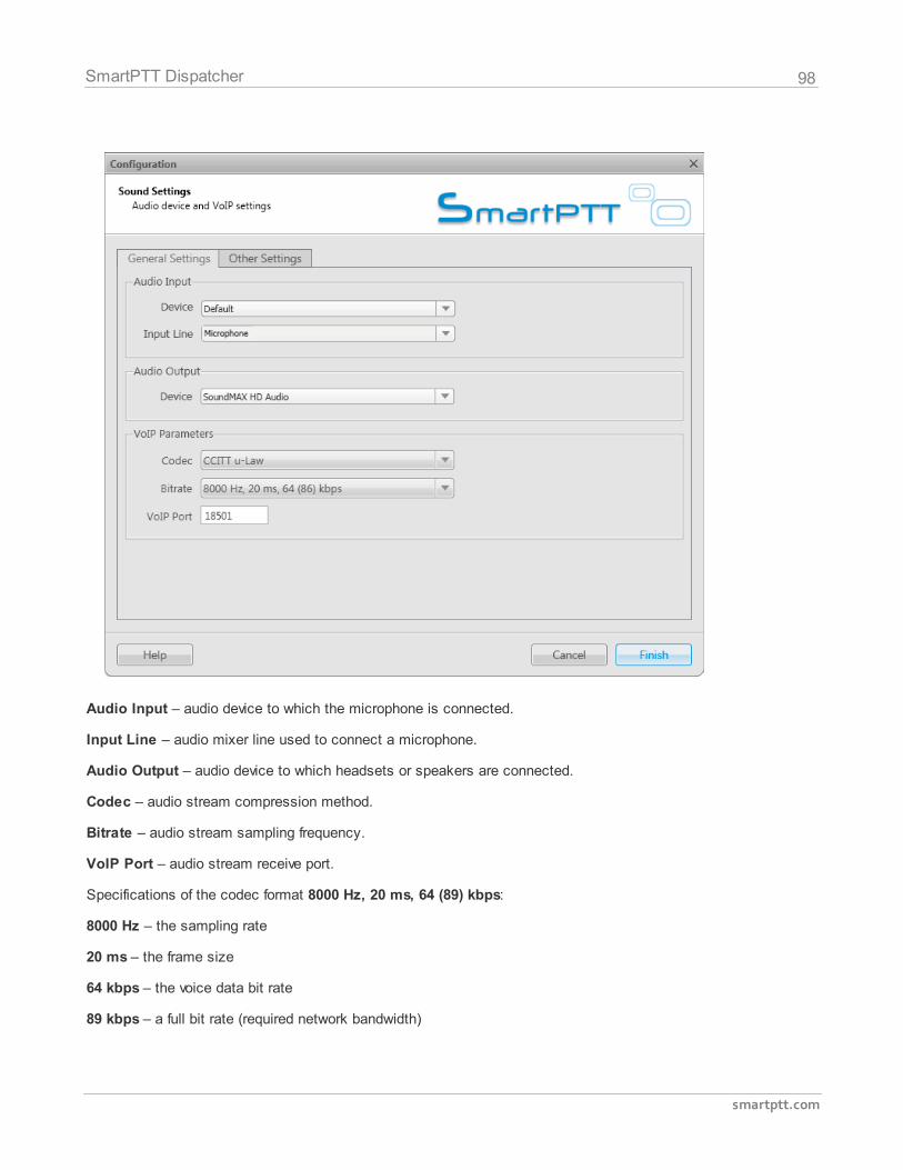
98
smartptt.com
SmartPTT Dispatcher
Audio Input – audio device to which the microphone is connected.
Input Line – audio mixer line used to connect a microphone.
Audio Output – audio device to which headsets or speakers are connected.
Codec – audio stream compression method.
Bitrate – audio stream sampling frequency.
VoIP Port – audio stream receive port.
Specifications of the codec format 8000 Hz, 20 ms, 64 (89) kbps:
8000 Hz – the sampling rate
20 ms – the frame size
64 kbps – the voice data bit rate
89 kbps – a full bit rate (required network bandwidth)
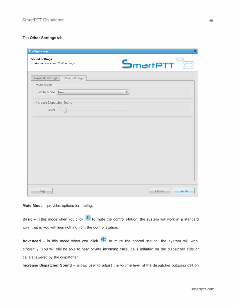
99
smartptt.com
SmartPTT Dispatcher
The Other Settings tab:
Mute Mode – provides options for muting.
Basic – in this mode when you click to mute the control station, the system will work in a standard
way, that is you will hear nothing from the control station.
Advanced – in this mode when you click to mute the control station, the system will work
differently. You will still be able to hear private incoming calls, calls initiated on the dispatcher side or
calls answered by the dispatcher.
Increase Dispatcher Sound – allows user to adjust the volume level of the dispatcher outgoing call on
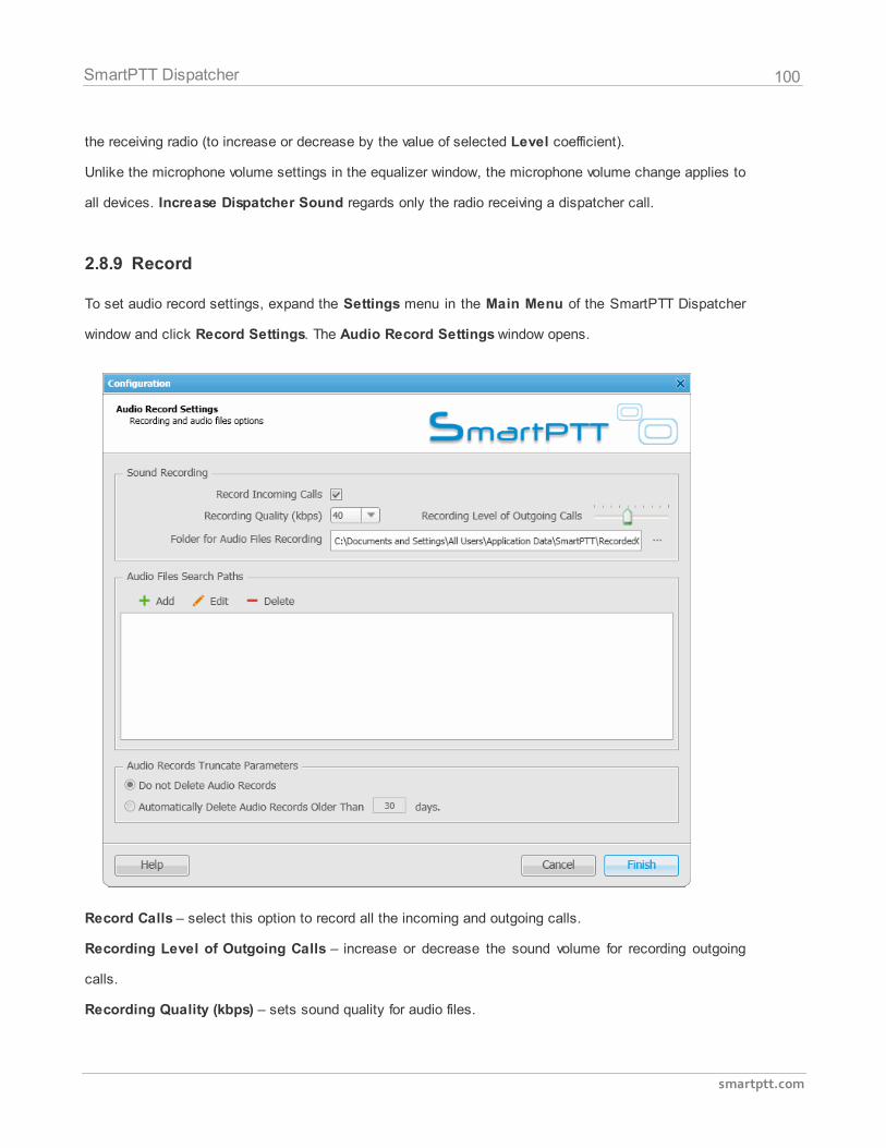
100
smartptt.com
SmartPTT Dispatcher
the receiving radio (to increase or decrease by the value of selected Level coefficient).
Unlike the microphone volume settings in the equalizer window, the microphone volume change applies to
all devices. Increase Dispatcher Sound regards only the radio receiving a dispatcher call.
2.8.9 Record
To set audio record settings, expand the Settings menu in the Main Menu of the SmartPTT Dispatcher
window and click Record Settings. The Audio Record Settings window opens.
Record Calls – select this option to record all the incoming and outgoing calls.
Recording Level of Outgoing Calls – increase or decrease the sound volume for recording outgoing
calls.
Recording Quality (kbps) – sets sound quality for audio files.
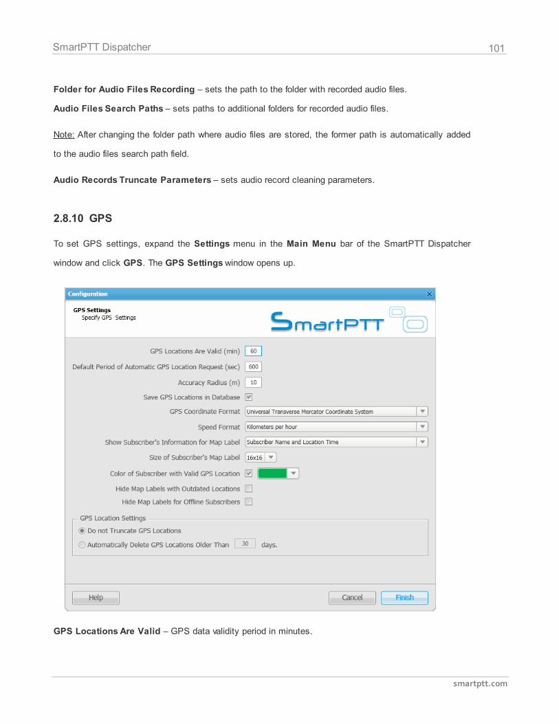
101
smartptt.com
SmartPTT Dispatcher
Folder for Audio Files Recording – sets the path to the folder with recorded audio files.
Audio Files Search Paths – sets paths to additional folders for recorded audio files.
Note: After changing the folder path where audio files are stored, the former path is automatically added
to the audio files search path field.
Audio Records Truncate Parameters – sets audio record cleaning parameters.
2.8.10 GPS
To set GPS settings, expand the Settings menu in the Main Menu bar of the SmartPTT Dispatcher
window and click GPS. The GPS Settings window opens up.
GPS Locations Are Valid – GPS data validity period in minutes.
102
smartptt.com
SmartPTT Dispatcher
Default Period of Automated GPS Location Request – interval of GPS data requests in seconds.
Accuracy Radius – sets the maximum coordinate error margin. If the received error value exceeds the
value specified in this field, the coordinate is invalid.
Save GPS Locations in Database – select the check box to store GPS coordinates received from
subscribers in the database.
GPS Coordinate Format – GPS coordinate format to display in the subscriber Call window:
Decimal degrees. GPS coordinates are displayed as: lat.: 56,47568, lon.:84,98779.
Degrees, Minutes, Seconds. GPS coordinates are displayed as: lat.: 56°28'32", lon.:84°59'16".
Universal Transverse Mercator Coordinate System. GPS coordinates are displayed as: 45V376108 B 6260913 C.
Speed Format – select the way to display subscriber speed.
Show Subscriber’s Information for Map Label – select the check box to permanently display
subscriber name and time of the last GPS coordinate behind subscriber map label.
Size of Subscriber’s Map Label – choose subscriber map label size.
Color of Subscriber with Valid GPS Location – set color of the subscriber name with valid GPS
locations.
Hide Map Labels with Outdated Locations – select the check box to hide map labels for subscribers
with outdated GPS locations. GPS location becomes outdated if it was not updated for more than the
period set in the GPS Locations Are Valid field.
Hide Map Labels for Offline Subscribers – select the check box to hide map labels when a subscriber
goes offline.
GPS Location Settings – settings to clear coordinates from the database.
2.8.11 Raster Map
To set raster map settings, expand the Settings menu in the Main Menu bar of the SmartPTT
Dispatcher window and click Raster Map. At that, the configuration window is displayed for creating
geographic raster maps based on an image.
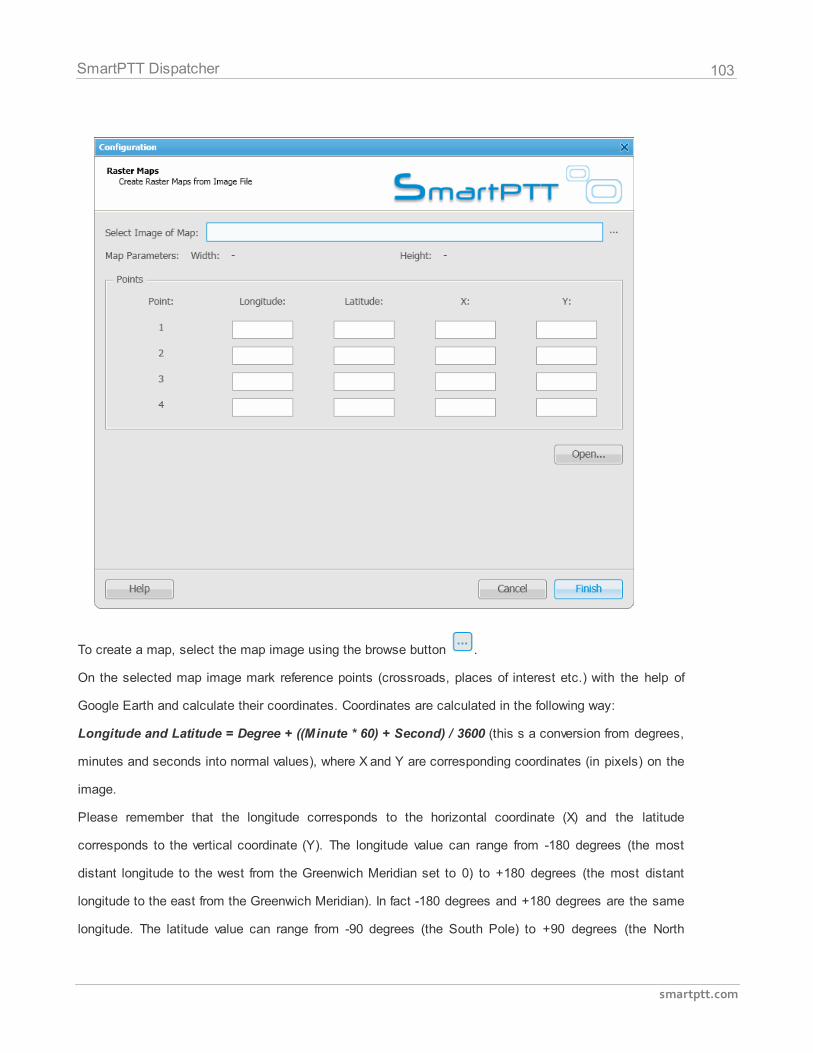
103
smartptt.com
SmartPTT Dispatcher
To create a map, select the map image using the browse button .
On the selected map image mark reference points (crossroads, places of interest etc.) with the help of
Google Earth and calculate their coordinates. Coordinates are calculated in the following way:
Longitude and Latitude = Degree + ((Minute * 60) + Second) / 3600 (this s a conversion from degrees,
minutes and seconds into normal values), where X and Y are corresponding coordinates (in pixels) on the
image.
Please remember that the longitude corresponds to the horizontal coordinate (X) and the latitude
corresponds to the vertical coordinate (Y). The longitude value can range from -180 degrees (the most
distant longitude to the west from the Greenwich Meridian set to 0) to +180 degrees (the most distant
longitude to the east from the Greenwich Meridian). In fact -180 degrees and +180 degrees are the same
longitude. The latitude value can range from -90 degrees (the South Pole) to +90 degrees (the North
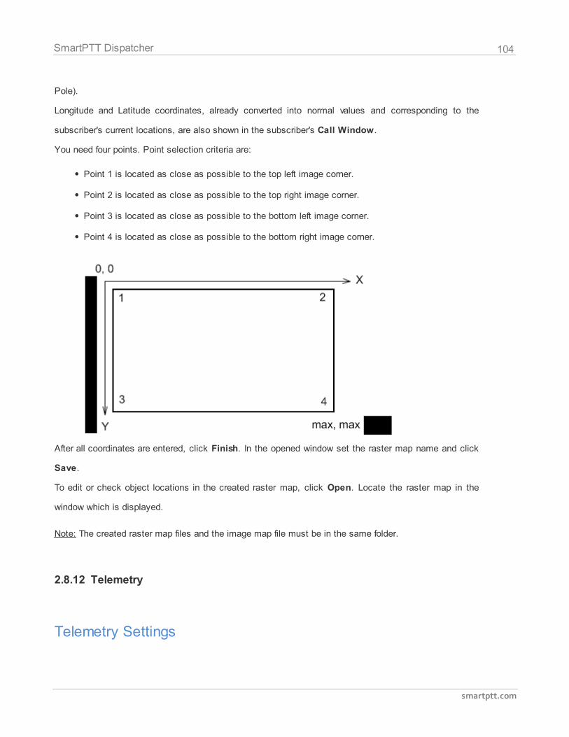
104
smartptt.com
SmartPTT Dispatcher
Pole).
Longitude and Latitude coordinates, already converted into normal values and corresponding to the
subscriber's current locations, are also shown in the subscriber's Call Window.
You need four points. Point selection criteria are:
Point 1 is located as close as possible to the top left image corner.
Point 2 is located as close as possible to the top right image corner.
Point 3 is located as close as possible to the bottom left image corner.
Point 4 is located as close as possible to the bottom right image corner.
After all coordinates are entered, click Finish. In the opened window set the raster map name and click
Save.
To edit or check object locations in the created raster map, click Open. Locate the raster map in the
window which is displayed.
Note: The created raster map files and the image map file must be in the same folder.
2.8.12 Telemetry
Telemetry Settings
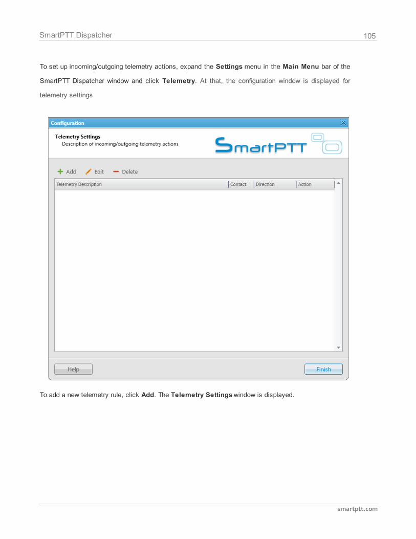
105
smartptt.com
SmartPTT Dispatcher
To set up incoming/outgoing telemetry actions, expand the Settings menu in the Main Menu bar of the
SmartPTT Dispatcher window and click Telemetry. At that, the configuration window is displayed for
telemetry settings.
To add a new telemetry rule, click Add. The Telemetry Settings window is displayed.
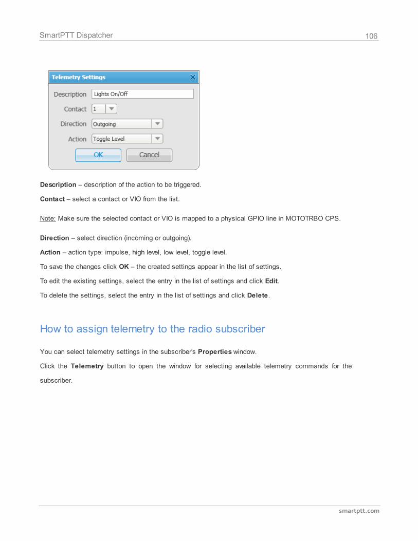
106
smartptt.com
SmartPTT Dispatcher
Description – description of the action to be triggered.
Contact – select a contact or VIO from the list.
Note: Make sure the selected contact or VIO is mapped to a physical GPIO line in MOTOTRBO CPS.
Direction – select direction (incoming or outgoing).
Action – action type: impulse, high level, low level, toggle level.
To save the changes click OK – the created settings appear in the list of settings.
To edit the existing settings, select the entry in the list of settings and click Edit.
To delete the settings, select the entry in the list of settings and click Delete.
How to assign telemetry to the radio subscriber
You can select telemetry settings in the subscriber's Properties window.
Click the Telemetry button to open the window for selecting available telemetry commands for the
subscriber.
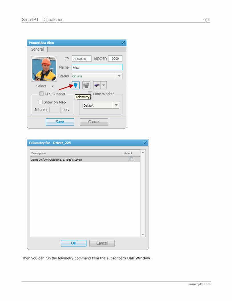
107
smartptt.com
SmartPTT Dispatcher
Then you can run the telemetry command from the subscriber's Call Window.
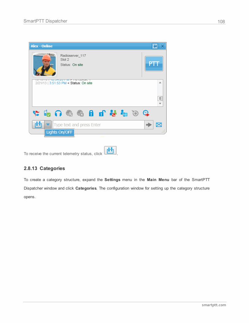
108
smartptt.com
SmartPTT Dispatcher
To receive the current telemetry status, click .
2.8.13 Categories
To create a category structure, expand the Settings menu in the Main Menu bar of the SmartPTT
Dispatcher window and click Categories. The configuration window for setting up the category structure
opens.
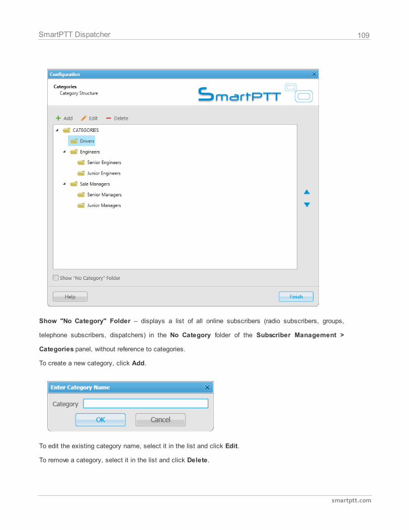
109
smartptt.com
SmartPTT Dispatcher
Show "No Category" Folder – displays a list of all online subscribers (radio subscribers, groups,
telephone subscribers, dispatchers) in the No Category folder of the Subscriber Management >
Categories panel, without reference to categories.
To create a new category, click Add.
To edit the existing category name, select it in the list and click Edit.
To remove a category, select it in the list and click Delete.
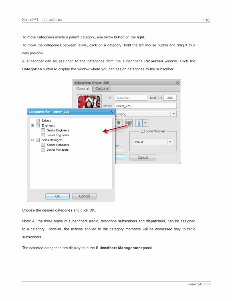
110
smartptt.com
SmartPTT Dispatcher
To move categories inside a parent category, use arrow button on the right.
To move the categories between levels, click on a category, hold the left mouse button and drag it to a
new position.
A subscriber can be assigned to the categories from the subscriber's Properties window. Click the
Categories button to display the window where you can assign categories to the subscriber.
Choose the desired categories and click OK.
Note: All the three types of subscribers (radio, telephone subscribers and dispatchers) can be assigned
to a category. However, the actions applied to the category members will be addressed only to radio
subscribers.
The selected categories are displayed in the Subscribers Management panel.
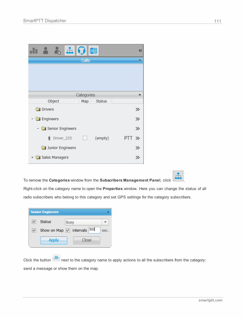
111
smartptt.com
SmartPTT Dispatcher
To remove the Categories window from the Subscribers Management Panel, click .
Right-click on the category name to open the Properties window. Here you can change the status of all
radio subscribers who belong to this category and set GPS settings for the category subscribers.
Click the button next to the category name to apply actions to all the subscribers from the category:
send a message or show them on the map.
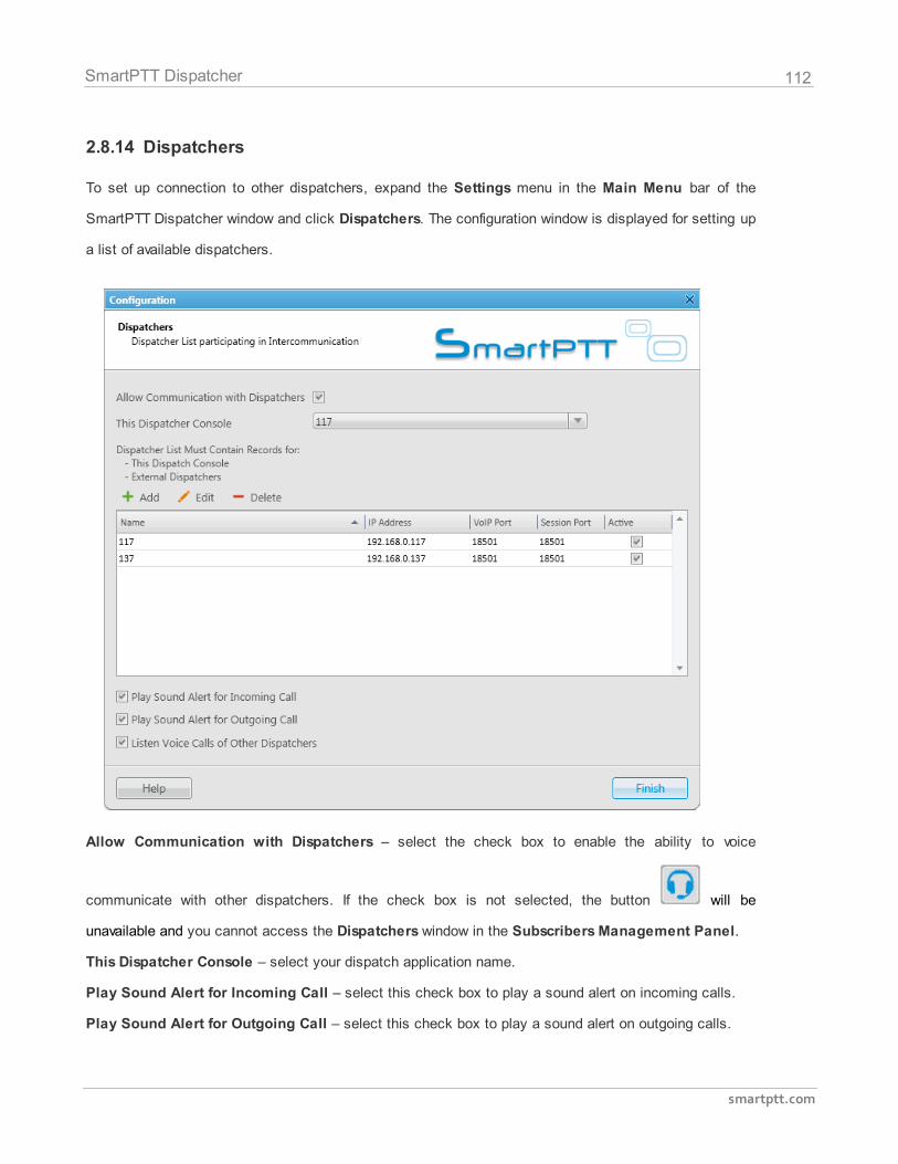
112
smartptt.com
SmartPTT Dispatcher
2.8.14 Dispatchers
To set up connection to other dispatchers, expand the Settings menu in the Main Menu bar of the
SmartPTT Dispatcher window and click Dispatchers. The configuration window is displayed for setting up
a list of available dispatchers.
Allow Communication with Dispatchers – select the check box to enable the ability to voice
communicate with other dispatchers. If the check box is not selected, the button will be
unavailable and you cannot access the Dispatchers window in the Subscribers Management Panel.
This Dispatcher Console – select your dispatch application name.
Play Sound Alert for Incoming Call – select this check box to play a sound alert on incoming calls.
Play Sound Alert for Outgoing Call – select this check box to play a sound alert on outgoing calls.
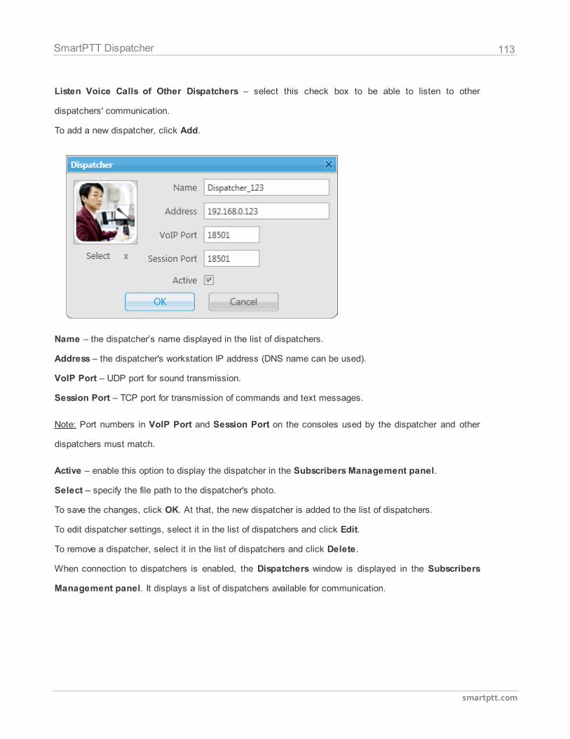
113
smartptt.com
SmartPTT Dispatcher
Listen Voice Calls of Other Dispatchers – select this check box to be able to listen to other
dispatchers' communication.
To add a new dispatcher, click Add.
Name – the dispatcher’s name displayed in the list of dispatchers.
Address – the dispatcher's workstation IP address (DNS name can be used).
VoIP Port – UDP port for sound transmission.
Session Port – TCP port for transmission of commands and text messages.
Note: Port numbers in VoIP Port and Session Port on the consoles used by the dispatcher and other
dispatchers must match.
Active – enable this option to display the dispatcher in the Subscribers Management panel.
Select – specify the file path to the dispatcher's photo.
To save the changes, click OK. At that, the new dispatcher is added to the list of dispatchers.
To edit dispatcher settings, select it in the list of dispatchers and click Edit.
To remove a dispatcher, select it in the list of dispatchers and click Delete.
When connection to dispatchers is enabled, the Dispatchers window is displayed in the Subscribers
Management panel. It displays a list of dispatchers available for communication.
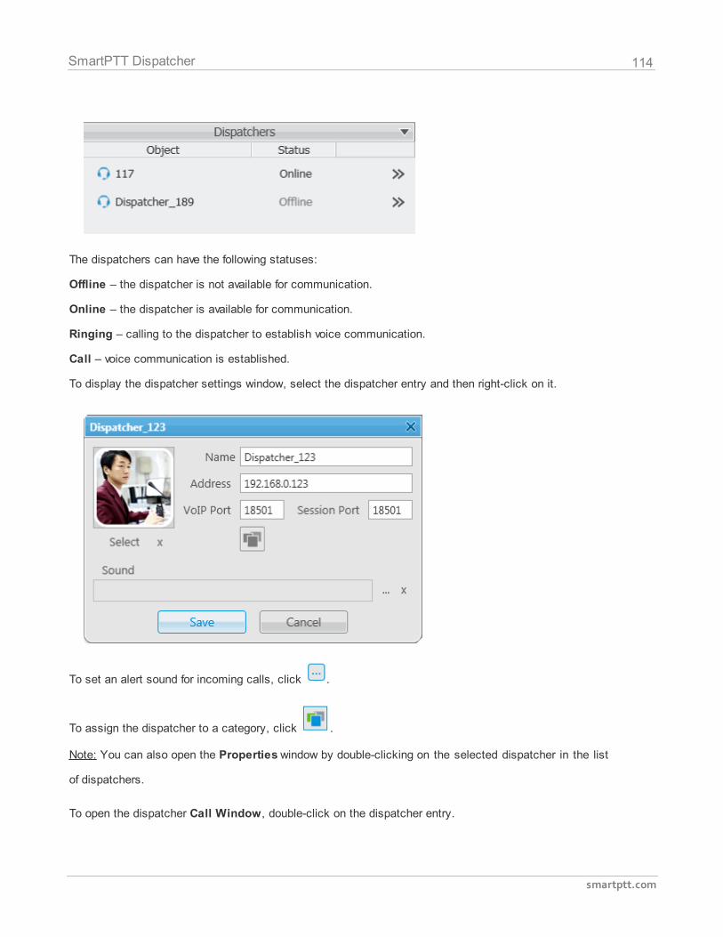
114
smartptt.com
SmartPTT Dispatcher
The dispatchers can have the following statuses:
Offline – the dispatcher is not available for communication.
Online – the dispatcher is available for communication.
Ringing – calling to the dispatcher to establish voice communication.
Call – voice communication is established.
To display the dispatcher settings window, select the dispatcher entry and then right-click on it.
To set an alert sound for incoming calls, click .
To assign the dispatcher to a category, click .
Note: You can also open the Properties window by double-clicking on the selected dispatcher in the list
of dispatchers.
To open the dispatcher Call Window, double-click on the dispatcher entry.
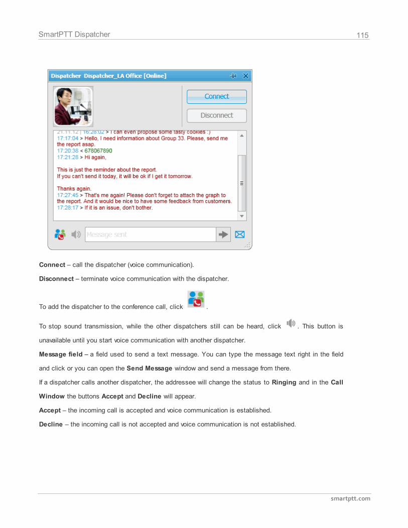
115
smartptt.com
SmartPTT Dispatcher
Connect – call the dispatcher (voice communication).
Disconnect – terminate voice communication with the dispatcher.
To add the dispatcher to the conference call, click .
To stop sound transmission, while the other dispatchers still can be heard, click . This button is
unavailable until you start voice communication with another dispatcher.
Message field – a field used to send a text message. You can type the message text right in the field
and click or you can open the Send Message window and send a message from there.
If a dispatcher calls another dispatcher, the addressee will change the status to Ringing and in the Call
Window the buttons Accept and Decline will appear.
Accept – the incoming call is accepted and voice communication is established.
Decline – the incoming call is not accepted and voice communication is not established.
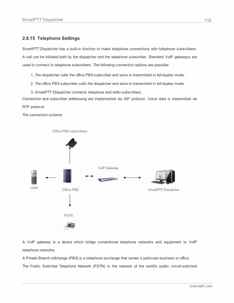
116
smartptt.com
SmartPTT Dispatcher
2.8.15 Telephone Settings
SmartPTT Dispatcher has a built-in function to make telephone connections with telephone subscribers.
A call can be initiated both by the dispatcher and the telephone subscriber. Standard VoIP gateways are
used to connect to telephone subscribers. The following connection options are possible:
1. The dispatcher calls the office PBX subscriber and voice is transmitted in full-duplex mode.
2. The office PBX subscriber calls the dispatcher and voice is transmitted in full-duplex mode.
3. SmartPTT Dispatcher connects telephone and radio subscribers.
Connection and subscriber addressing are implemented via SIP protocol. Voice data is transmitted via
RTP protocol.
The connection scheme
A VoIP gateway is a device which bridge conventional telephone networks and equipment to VoIP
telephone networks.
A Private Branch eXchange (PBX) is a telephone exchange that serves a particular business or office.
The Public Switched Telephone Network (PSTN) is the network of the world's public circuit-switched
117
smartptt.com
SmartPTT Dispatcher
telephone networks.
SIP Architecture
Call service management is distributed between different elements of SIP network. The basic functional
unit that implements connection management are User Agents, which are endpoints of a call (that is
each of the participants in a call). The remaining network elements (SIP-servers) are responsible for call
routing and can provide additional services.
1. User Agents
User agents are both the computer that is being used to make a call, and the target computer that is
being called. These make the two endpoints of the communication session. There are two components to
a user agent: a client and a server. When a user agent makes a request (such as initiating a session), it
is the User Agent Client (UAC), and the user agent responding to the request is the User Agent Server
(UAS). Even though other devices that we’ll discuss are optional to various degrees, User Agents must
exist for a SIP session to be established.
2. Proxy Server
Proxy servers are computers that are used to forward requests on behalf of other computers. If a SIP
server receives a request from a client, it can forward the request onto another SIP server on the network.
While functioning as a proxy server, the SIP server can provide such functions as network access control,
security, authentication, and authorization.
3. Registrar Server
Registrar servers are used to register the location of a user agent who has logged onto the network. It
obtains the IP address of the user and associates it with their user name on the system. This creates a
directory of all those who are currently logged onto the network, and where they are located. When
someone wishes to establish a session with one of these users, the Registrar server’s information is
referred to, thereby identifying the IP addresses of those involved in the session.
4. Redirect Server
The Redirect servers are used by SIP to redirect clients to the user agent they are attempting to contact.
If a user agent makes a request, the Redirect server can respond with the IP address of the user agent
118
smartptt.com
SmartPTT Dispatcher
being contacted. This is different from a Proxy server, which forwards the request on your behalf, as the
Redirect server essentially tells you to contact them yourself.
SIP determines the following addressing system: [sip:] id [@ fragment]. ID indicates user name or
phone number of the subscriber. Fragment specifies the host, which can be set to the domain name, the
IP-address of the computer or the address of the VoIP gateway. Caller ID can be presented in different
ways, such as user_name@[domain name], name@[IPaddress], phone_number@[VoIPgateway].
SIP Connection Methods
There are two SIP connection types – SIP trunking and using a SIP account.
SIP trunking is used when a user agent (SmartPTT Dispatcher in our case) has a static IP address. This
IP address must be prescribed on SIP server only once, and the client does not require to re-register on
the SIP server. SIP trunking provides security by means of password authentication for incoming and
outgoing calls.
If the client IP address changes periodically, use a SIP server account to establish the connection. When
the client turns on, it sends a special package for SIP registration to the server. The package contains
authentication data (SIP account user name, login, password) and the current IP address. Since then
server knows where to route calls addressed to the client. After a period of time the client automatically
updates the registration. If its IP address has changed, SIP server accordingly updates the information on
this user.
Telephone Settings Configuration
To configure connection parameters with telephone subscribers, expand the Settings menu in the Main
Menu bar of the SmartPTT Dispatcher window and click Telephone Settings. The configuration window
is displayed for configuring connection parameters.
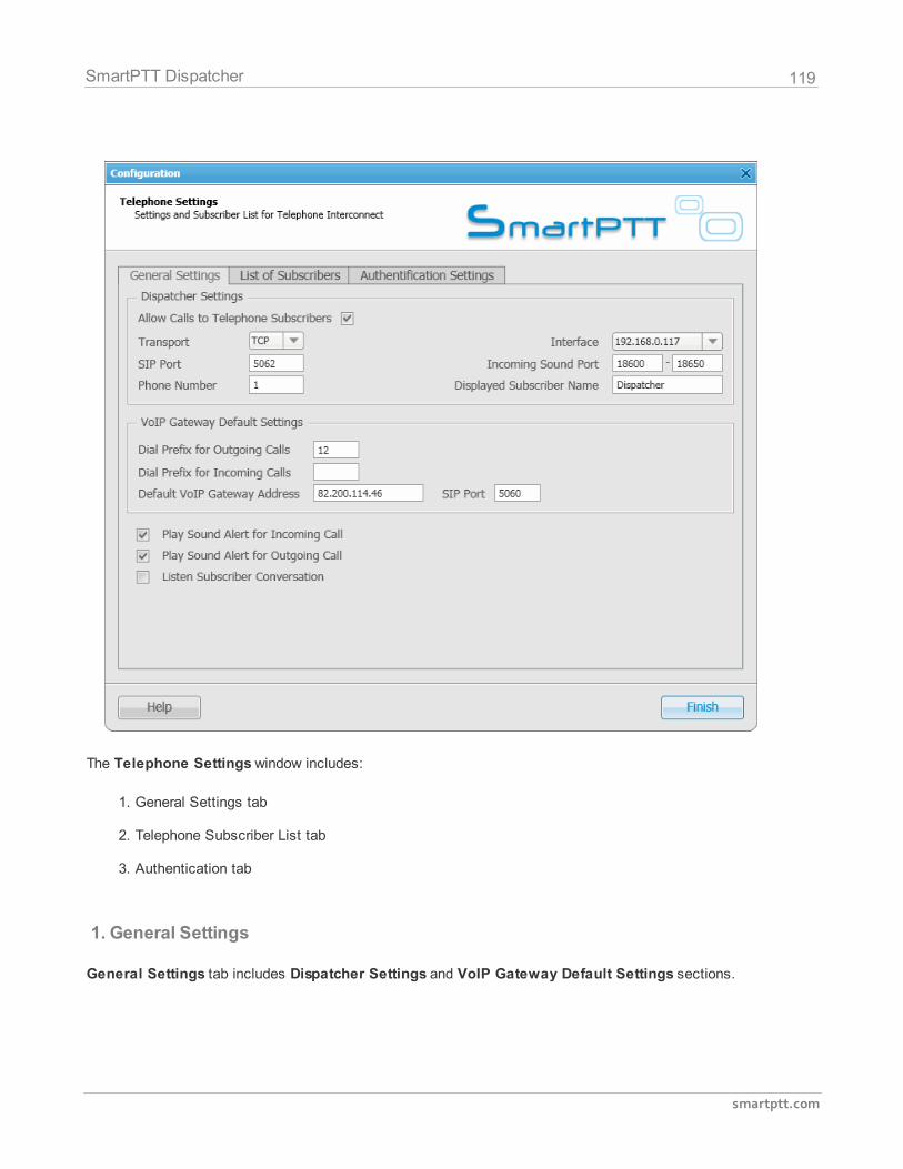
119
smartptt.com
SmartPTT Dispatcher
The Telephone Settings window includes:
1. General Settings tab
2. Telephone Subscriber List tab
3. Authentication tab
1. General Settings
General Settings tab includes Dispatcher Settings and VoIP Gateway Default Settings sections.
120
smartptt.com
SmartPTT Dispatcher
1.1 Dispatcher Settings
Allow Calls to Telephone Subscribers – select the check box to be able to make and receive calls
between SmartPTT Dispatcher and telephone subscribers.
Note: If the check box is not selected, the Telephone Subscribers window is unavailable.
Incoming Sound Port – each connection with the telephone subscriber requires two UDP ports (even
port numbers are used by RTP protocol, uneven – by RTCP). Thus, the specified ports must be available
both for incoming and outgoing traffic.
Interface – IP address of the local computer, used to receive and transmit commands and voice data. If
the dispatcher's computer has only one IP address, the system can select it automatically; if it has more
than one IP address, the IP address (interface) should be specified expressly. The specified IP must be
available from the VoIP gateway end.
Warning! If several network interfaces are installed on the computer you may have to configure
the routing table using the command "route add ...".
SIP Port – UDP or TCP port number to receive and send SIP data packets. The default value is 5060.
Accordingly, the specified port must be available for incoming and outgoing traffic.
Displayed Telephone Number – type the telephone number which allows you to connect to SmartPTT
Dispatcher. This number is also displayed on the screen of the receiving SIP call device (phone or
softphone).
Displayed Subscriber Name – type the name to be displayed on the screen of the receiving SIP call
device (phone or softphone).
1.2 VoIP Gateway Default Settings
If VoIP Gateway Default Settings are specified, it is enough to set only subscriber phone numbers in
the List of Subscribers tab. Also, these parameters are used to dial the called subscriber number
manually (click the Dial Pad button and the Dial Pad window opens).
Default VoIP Gateway Address – the VoIP gateway IP address.
121
smartptt.com
SmartPTT Dispatcher
SIP Port – a VoIP gateway to receive and send SIP data packets. By default VoIP gateways use the
UDP port 5060.
Dial Prefix for Outgoing Calls – numeric prefix added to the called subscriber number by SmartPTT
Dispatcher. VoIP gateway uses the prefix to determine where the call came from and what rules it must
apply to the call (block or allow, where the call must be routed).
Dial Prefix for Incoming Calls – numeric prefix value in this field must match the same VoIP gateway
prefix.
If default VoIP gateway is used, the telephone subscriber's complete SIP address will be as follows:
SIP address = Dial Prefix for Outgoing Calls + Phone Number + @ + Default VoIP Gateway
Address + : + Gateway SIP Port.
Example:
If the following settings are used:
Default VoIP Gateway Address = 192.168.0.243
SIP Port = 5060
Dial Prefix for Outgoing Calls = 12
The telephone subscriber with the phone number 1140 is automatically assigned the following outgoing SIP
address = [email protected]:5060.
Play Sound Alert for Incoming Call – select the check box to enable ringing at the SmartPTT
Dispatcher application when a telephone subscriber calls.
Play Sound Alert for Outgoing Call – select the check box to enable ringing at the SmartPTT
Dispatcher application when making a call to a telephone subscriber.
Listen Subscriber Conversation – select the check box to allow the dispatcher to listen to the
conversation between the radio and telephone subscriber.
Note: If your network uses a firewall, consult a network administrator about the possibility of using SIP
protocol and the required settings. The most common problem is that the media streams (for example,
voice) are transferred over dynamically assigned UDP ports that are generally closed. The firewall must
be able to dynamically open and close ports based on the transferred SIP signaling. Another problem is
122
smartptt.com
SmartPTT Dispatcher
that the SIP clients inside the firewall cannot be reached by IP addresses since these most often are
private and local to the LAN. Communication simply does not take place, unless there is specific SIP
support in the firewall.
1.3 VoIP Gateway Configuration
The VoIP gateway administrator must ensure that SIP addresses for incoming calls are appropriately
interpreted and switched to phone numbers.
In the example above the telephone subscriber address is sip:[email protected]:5060 and the dial
prefix for outgoing calls is 12. Therefore VoIP gateway rules must discard the incoming prefix 12 from the
full address and connect the dispatcher to the telephone subscriber number, that is 1140.
You should also configure appropriate generation rules for outgoing SIP addresses to call other
dispatchers.
For example, if the telephone subscriber with the number 1140 assigned wants to connect to the
dispatcher with the address 192.168.0.105:5060, then generation rules for outgoing SIP addresses on the
VoIP gateway must generate the correct destination address sip:[email protected]:5060 (the Displayed
Telephone Number value must be set as the SmartPTT Dispatcher identifier) and the sender's correct
address sip:[email protected]:5060 (a dial prefix for incoming addresses is not set so the name in the
sender's address is the same as the phone number).
2. Telephone Subscriber List
The Telephone Settings window contains Telephone Subscriber List. The list includes all telephone
subscribers that maintain SIP connection. You can modify the existing subscribers or add new
subscribers.
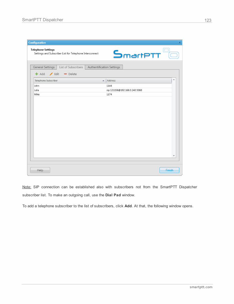
123
smartptt.com
SmartPTT Dispatcher
Note: SIP connection can be established also with subscribers not from the SmartPTT Dispatcher
subscriber list. To make an outgoing call, use the Dial Pad window.
To add a telephone subscriber to the list of subscribers, click Add. At that, the following window opens.
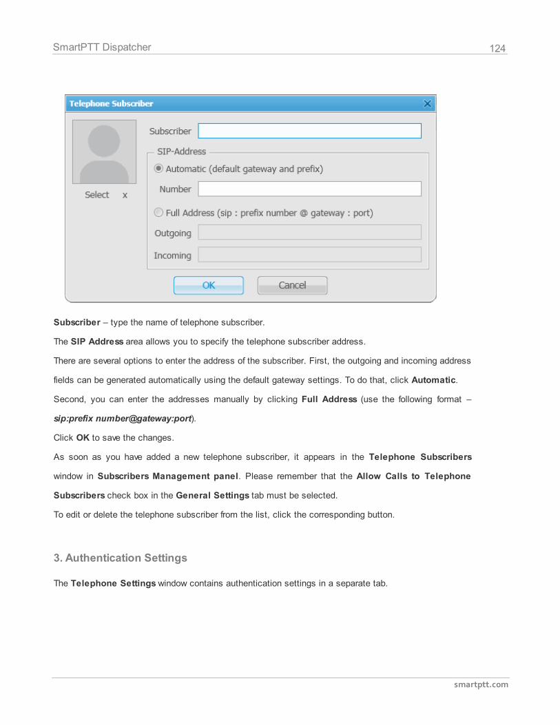
124
smartptt.com
SmartPTT Dispatcher
Subscriber – type the name of telephone subscriber.
The SIP Address area allows you to specify the telephone subscriber address.
There are several options to enter the address of the subscriber. First, the outgoing and incoming address
fields can be generated automatically using the default gateway settings. To do that, click Automatic.
Second, you can enter the addresses manually by clicking Full Address (use the following format –
sip:prefix number@gateway:port).
Click OK to save the changes.
As soon as you have added a new telephone subscriber, it appears in the Telephone Subscribers
window in Subscribers Management panel. Please remember that the Allow Calls to Telephone
Subscribers check box in the General Settings tab must be selected.
To edit or delete the telephone subscriber from the list, click the corresponding button.
3. Authentication Settings
The Telephone Settings window contains authentication settings in a separate tab.
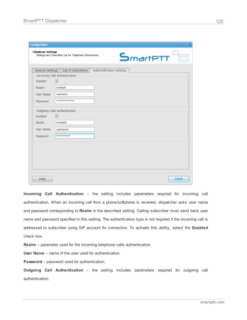
125
smartptt.com
SmartPTT Dispatcher
Incoming Call Authentication – the setting includes parameters required for incoming call
authentication. When an incoming call from a phone/softphone is received, dispatcher asks user name
and password corresponding to Realm in the described setting. Calling subscriber must send back user
name and password specified in this setting. The authentication type is not required if the incoming call is
addressed to subscriber using SIP account for connection. To activate this ability, select the Enabled
check box.
Realm – parameter used for the incoming telephone calls authentication.
User Name – name of the user used for authentication.
Password – password used for authentication.
Outgoing Call Authentication – the setting includes parameters required for outgoing call
authentication.
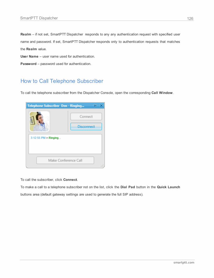
126
smartptt.com
SmartPTT Dispatcher
Realm – if not set, SmartPTT Dispatcher responds to any any authentication request with specified user
name and password. If set, SmartPTT Dispatcher responds only to authentication requests that matches
the Realm value.
User Name – user name used for authentication.
Password – password used for authentication.
How to Call Telephone Subscriber
To call the telephone subscriber from the Dispatcher Console, open the corresponding Call Window.
To call the subscriber, click Connect.
To make a call to a telephone subscriber not on the list, click the Dial Pad button in the Quick Launch
buttons area (default gateway settings are used to generate the full SIP address).
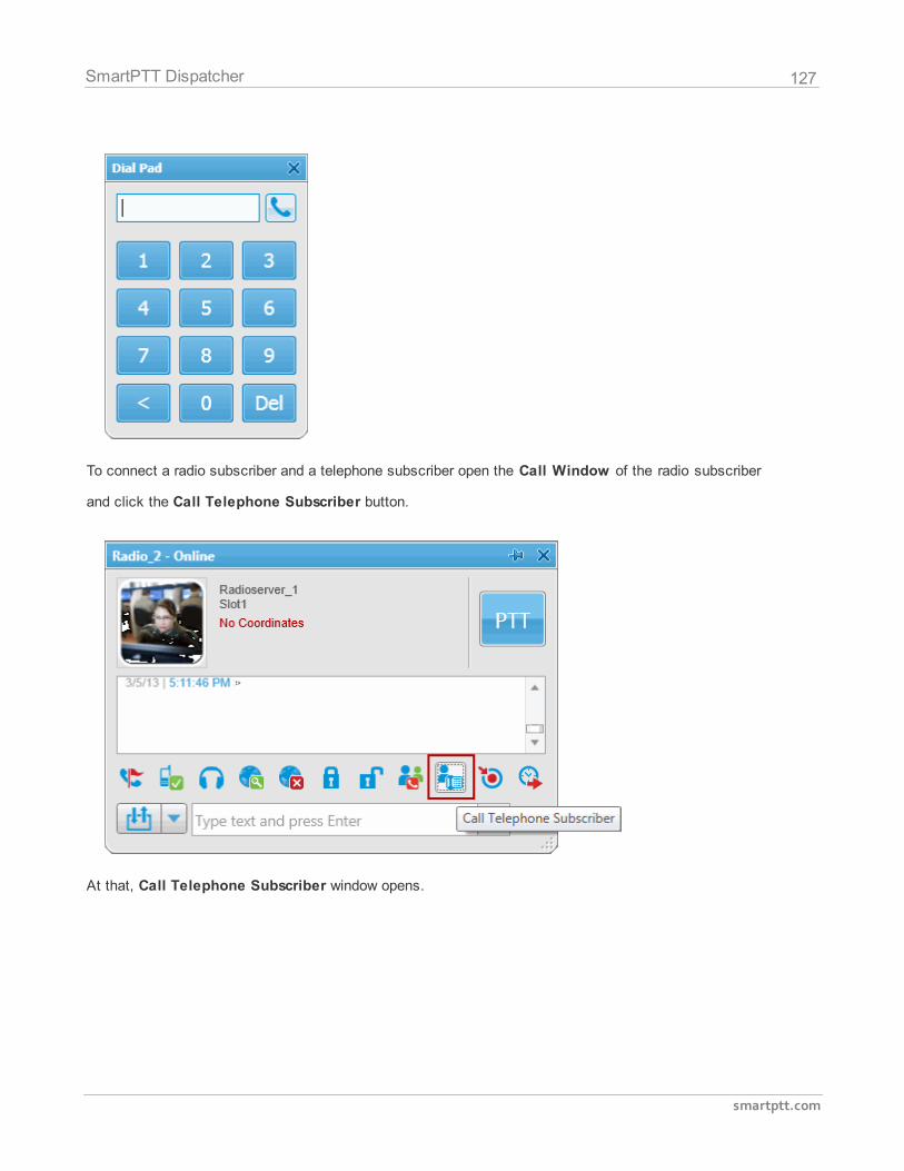
127
smartptt.com
SmartPTT Dispatcher
To connect a radio subscriber and a telephone subscriber open the Call Window of the radio subscriber
and click the Call Telephone Subscriber button.
At that, Call Telephone Subscriber window opens.
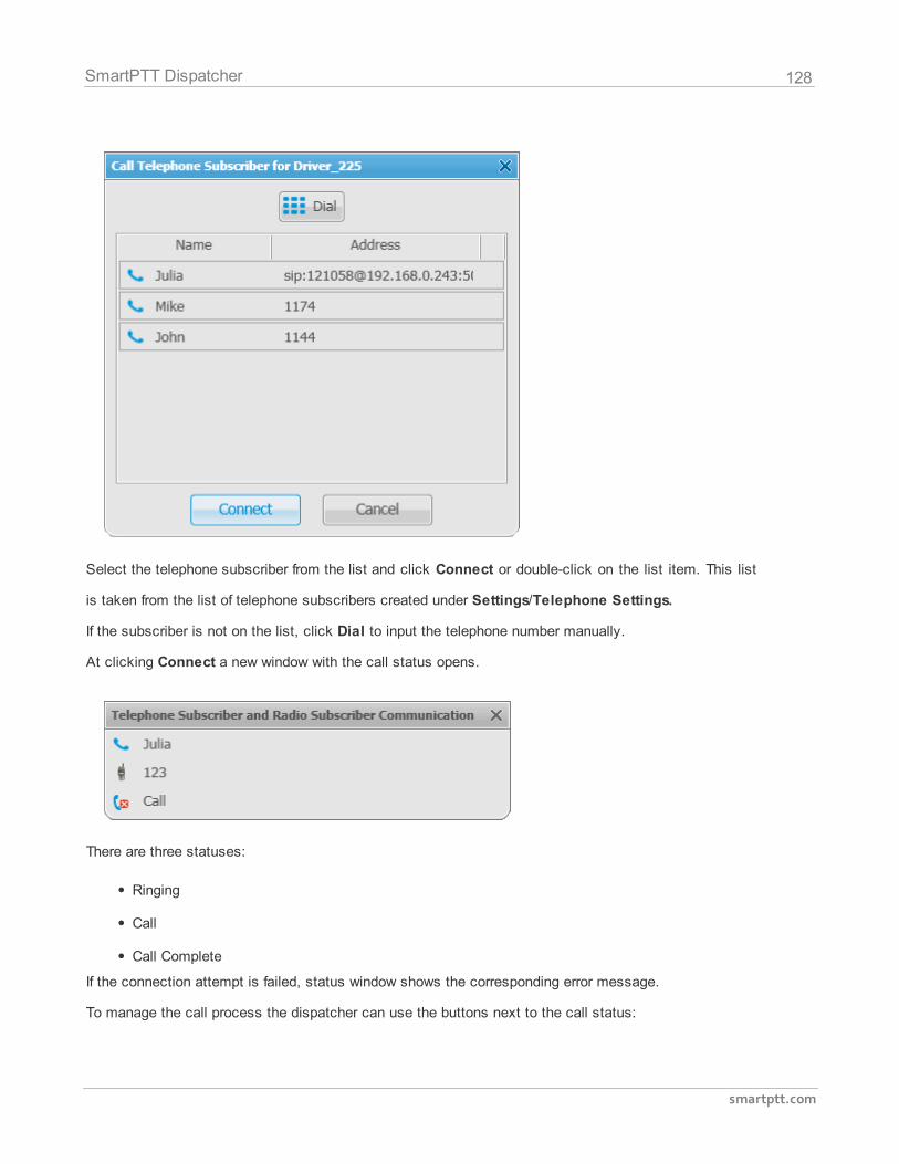
128
smartptt.com
SmartPTT Dispatcher
Select the telephone subscriber from the list and click Connect or double-click on the list item. This list
is taken from the list of telephone subscribers created under Settings/Telephone Settings.
If the subscriber is not on the list, click Dial to input the telephone number manually.
At clicking Connect a new window with the call status opens.
There are three statuses:
Ringing
Call
Call Complete
If the connection attempt is failed, status window shows the corresponding error message.
To manage the call process the dispatcher can use the buttons next to the call status:
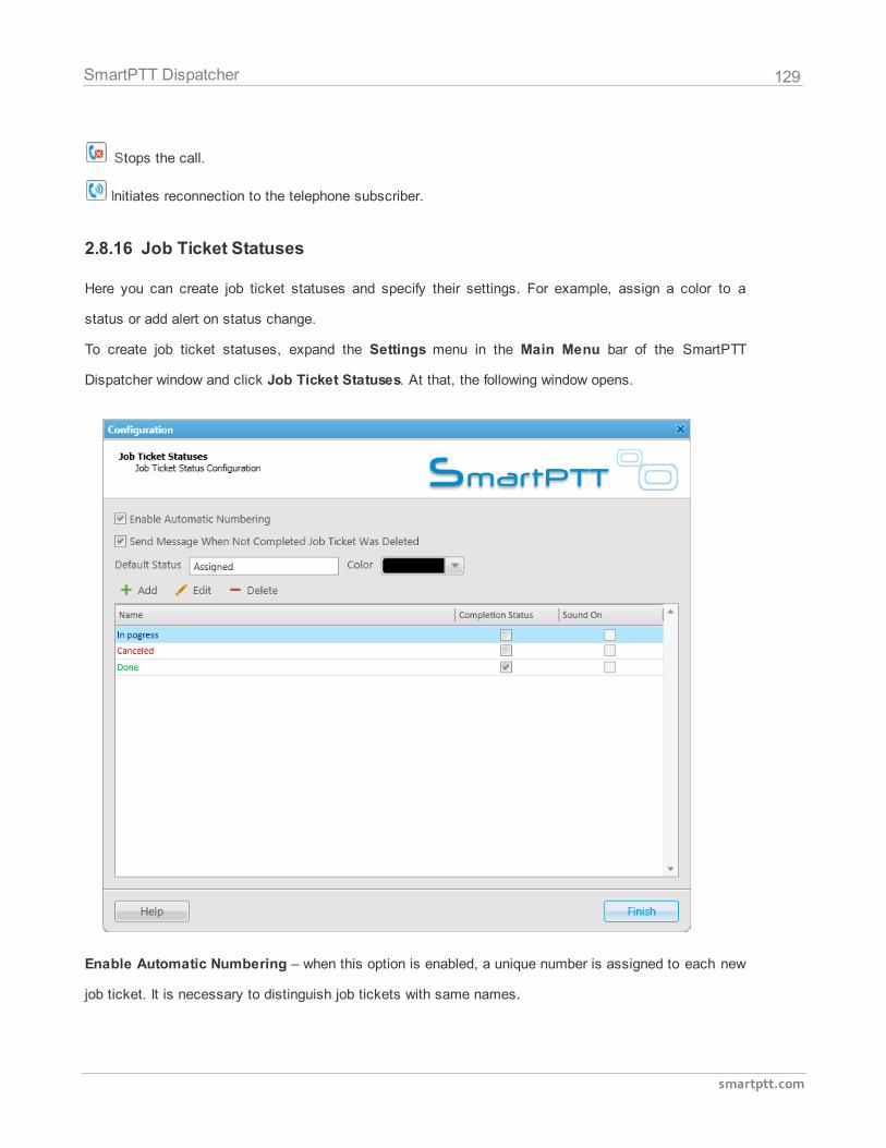
129
smartptt.com
SmartPTT Dispatcher
Stops the call.
Initiates reconnection to the telephone subscriber.
2.8.16 Job Ticket Statuses
Here you can create job ticket statuses and specify their settings. For example, assign a color to a
status or add alert on status change.
To create job ticket statuses, expand the Settings menu in the Main Menu bar of the SmartPTT
Dispatcher window and click Job Ticket Statuses. At that, the following window opens.
Enable Automatic Numbering – when this option is enabled, a unique number is assigned to each new
job ticket. It is necessary to distinguish job tickets with same names.
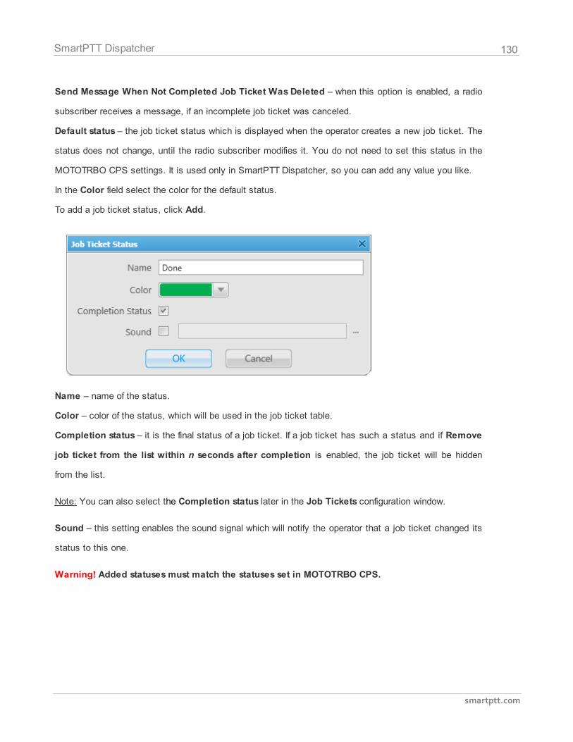
130
smartptt.com
SmartPTT Dispatcher
Send Message When Not Completed Job Ticket Was Deleted – when this option is enabled, a radio
subscriber receives a message, if an incomplete job ticket was canceled.
Default status – the job ticket status which is displayed when the operator creates a new job ticket. The
status does not change, until the radio subscriber modifies it. You do not need to set this status in the
MOTOTRBO CPS settings. It is used only in SmartPTT Dispatcher, so you can add any value you like.
In the Color field select the color for the default status.
To add a job ticket status, click Add.
Name – name of the status.
Color – color of the status, which will be used in the job ticket table.
Completion status – it is the final status of a job ticket. If a job ticket has such a status and if Remove
job ticket from the list within n seconds after completion is enabled, the job ticket will be hidden
from the list.
Note: You can also select the Completion status later in the Job Tickets configuration window.
Sound – this setting enables the sound signal which will notify the operator that a job ticket changed its
status to this one.
Warning! Added statuses must match the statuses set in MOTOTRBO CPS.
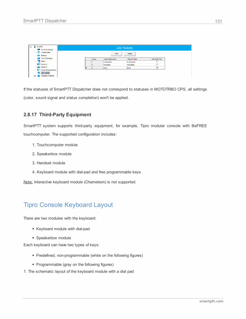
131
smartptt.com
SmartPTT Dispatcher
If the statuses of SmartPTT Dispatcher does not correspond to statuses in MOTOTRBO CPS, all settings
(color, sound signal and status completion) won't be applied.
2.8.17 Third-Party Equipment
SmartPTT system supports third-party equipment, for example, Tipro modular console with BeFREE
touchcomputer. The supported configuration includes:
1. Touchcomputer module
2. Speakerbox module
3. Handset module
4. Keyboard module with dial-pad and free programmable keys
Note: Interactive keyboard module (Chameleon) is not supported.
Tipro Console Keyboard Layout
There are two modules with the keyboard:
Keyboard module with dial-pad
Speakerbox module
Each keyboard can have two types of keys:
Predefined, non-programmable (white on the following figures)
Programmable (gray on the following figures)
1. The schematic layout of the keyboard module with a dial pad
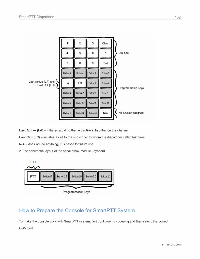
132
smartptt.com
SmartPTT Dispatcher
Last Active (LA) – initiates a call to the last active subscriber on the channel.
Last Call (LC) – initiates a call to the subscriber to whom the dispatcher called last time.
N/A – does not do anything, it is saved for future use.
2. The schematic layout of the speakerbox module keyboard
How to Prepare the Console for SmartPTT System
To make the console work with SmartPTT system, first configure its codeplug and then select the correct
COM port.
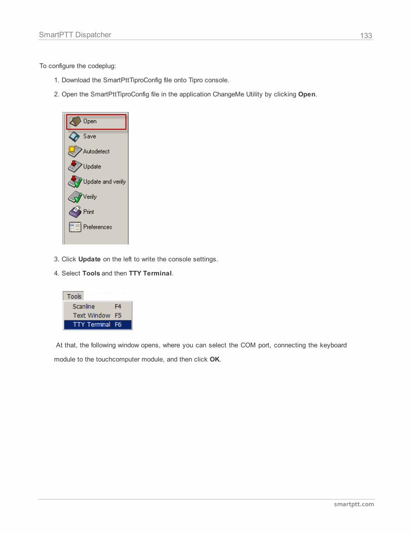
133
smartptt.com
SmartPTT Dispatcher
To configure the codeplug:
1. Download the SmartPttTiproConfig file onto Tipro console.
2. Open the SmartPttTiproConfig file in the application ChangeMe Utility by clicking Open.
3. Click Update on the left to write the console settings.
4. Select Tools and then TTY Terminal.
At that, the following window opens, where you can select the COM port, connecting the keyboard
module to the touchcomputer module, and then click OK.
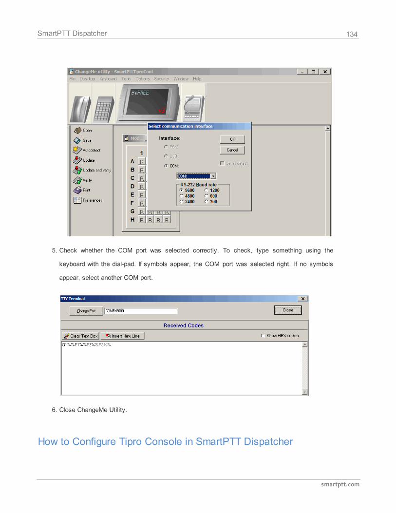
134
smartptt.com
SmartPTT Dispatcher
5. Check whether the COM port was selected correctly. To check, type something using the
keyboard with the dial-pad. If symbols appear, the COM port was selected right. If no symbols
appear, select another COM port.
6. Close ChangeMe Utility.
How to Configure Tipro Console in SmartPTT Dispatcher
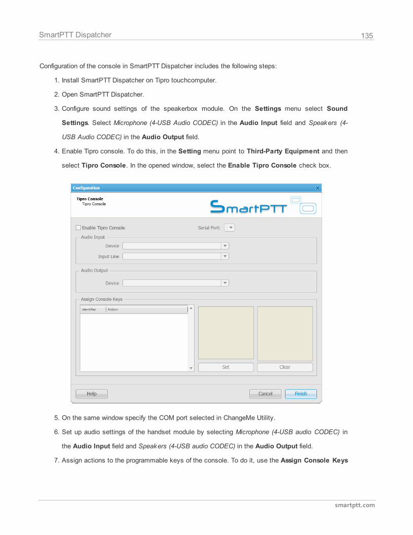
135
smartptt.com
SmartPTT Dispatcher
Configuration of the console in SmartPTT Dispatcher includes the following steps:
1. Install SmartPTT Dispatcher on Tipro touchcomputer.
2. Open SmartPTT Dispatcher.
3. Configure sound settings of the speakerbox module. On the Settings menu select Sound
Settings. Select Microphone (4-USB Audio CODEC) in the Audio Input field and Speakers (4-
USB Audio CODEC) in the Audio Output field.
4. Enable Tipro console. To do this, in the Setting menu point to Third-Party Equipment and then
select Tipro Console. In the opened window, select the Enable Tipro Console check box.
5. On the same window specify the COM port selected in ChangeMe Utility.
6. Set up audio settings of the handset module by selecting Microphone (4-USB audio CODEC) in
the Audio Input field and Speakers (4-USB audio CODEC) in the Audio Output field.
7. Assign actions to the programmable keys of the console. To do it, use the Assign Console Keys
136
smartptt.com
SmartPTT Dispatcher
area.
The area contains three boxes:
1) The first box is a list of Identifiers and Actions. Identifiers represent programmable keys
of the keyboard module. Actions stand for the actions which will be executed at pressing
the corresponding key.
2) The second box represents a list of actions which can be assigned to a key. The list is
always the same and includes the items:
Select Radio
Select Group
Select Control Station
Select Dispatcher
Select PBX Subscriber
3) The third box is a list of registered radio subscribers, all available groups and control
stations, registered telephone subscribers and dispatchers. The list changes depending on
the item selected in the second box.
To assign an action to a key:
1. In the first box select a free key to assign an action.
2. In the second box select the action itself.
3. In the third box select subscribers/groups/control stations or dispatchers.
4. To add a record with the new key assignment, click Set and then Finish.
To delete a record from the first box, click Clear.
2.8.18 Hot Keys
SmartPTT Dispatcher implements the ability to make a call to subscribers (a radio subscriber, a group of
subscribers, an All Call, a telephone subscriber, an external dispatcher) by clicking on a predetermined
keyboard key or its combination. Also, dispatcher can repeat the last outgoing call or respond to the last
incoming call by pressing the hot keys.
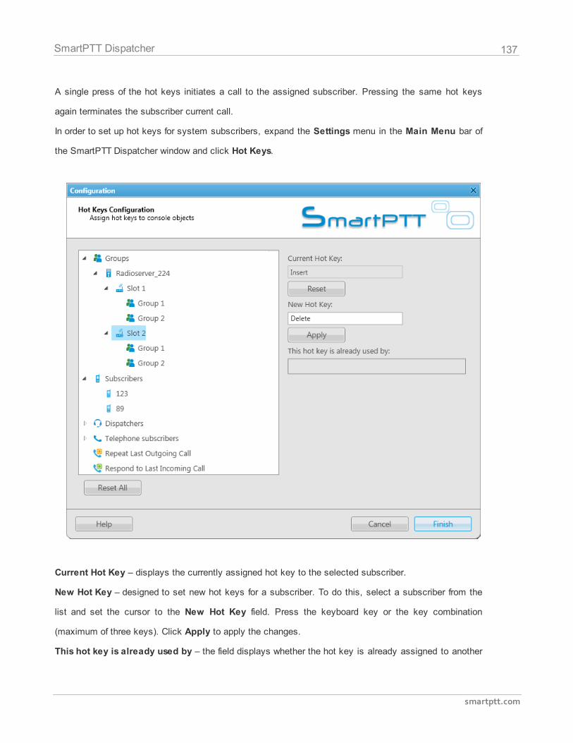
137
smartptt.com
SmartPTT Dispatcher
A single press of the hot keys initiates a call to the assigned subscriber. Pressing the same hot keys
again terminates the subscriber current call.
In order to set up hot keys for system subscribers, expand the Settings menu in the Main Menu bar of
the SmartPTT Dispatcher window and click Hot Keys.
Current Hot Key – displays the currently assigned hot key to the selected subscriber.
New Hot Key – designed to set new hot keys for a subscriber. To do this, select a subscriber from the
list and set the cursor to the New Hot Key field. Press the keyboard key or the key combination
(maximum of three keys). Click Apply to apply the changes.
This hot key is already used by – the field displays whether the hot key is already assigned to another
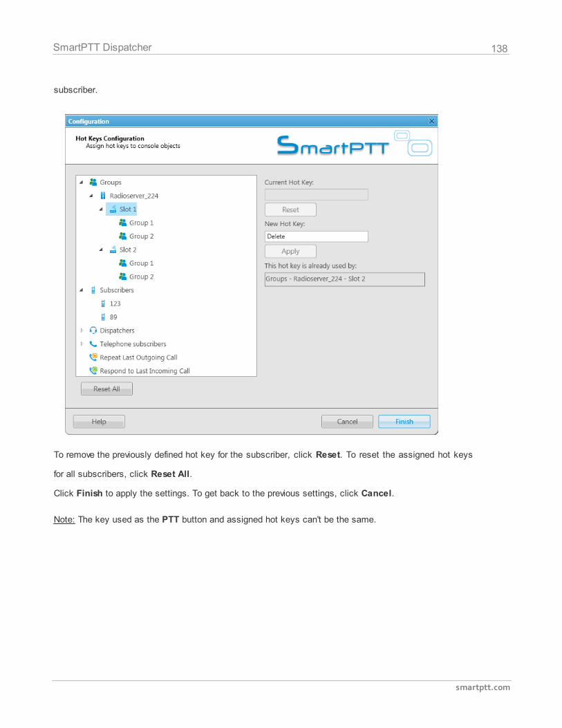
138
smartptt.com
SmartPTT Dispatcher
subscriber.
To remove the previously defined hot key for the subscriber, click Reset. To reset the assigned hot keys
for all subscribers, click Reset All.
Click Finish to apply the settings. To get back to the previous settings, click Cancel.
Note: The key used as the PTT button and assigned hot keys can't be the same.
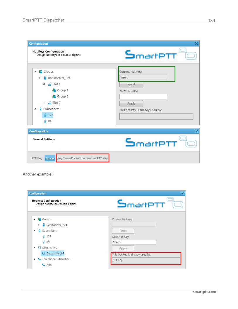
139
smartptt.com
SmartPTT Dispatcher
Another example:
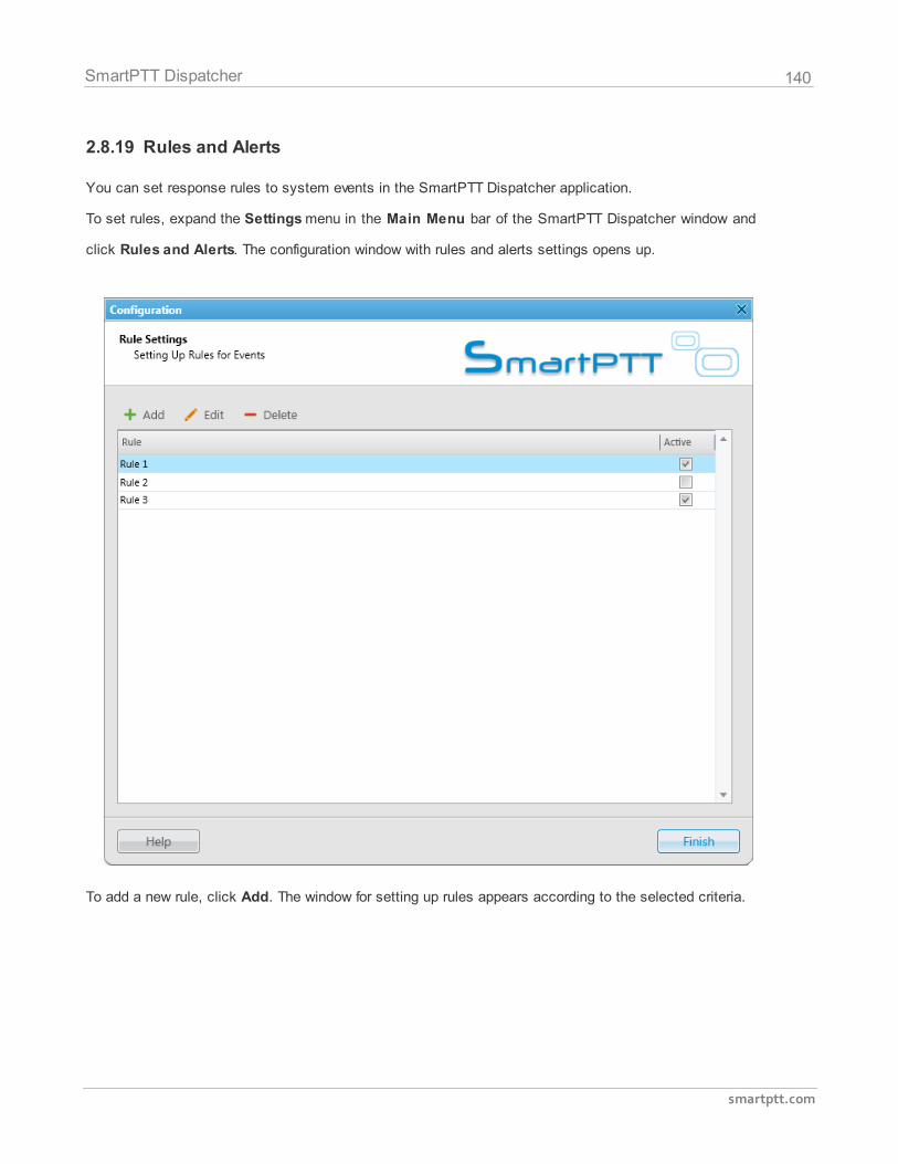
140
smartptt.com
SmartPTT Dispatcher
2.8.19 Rules and Alerts
You can set response rules to system events in the SmartPTT Dispatcher application.
To set rules, expand the Settings menu in the Main Menu bar of the SmartPTT Dispatcher window and
click Rules and Alerts. The configuration window with rules and alerts settings opens up.
To add a new rule, click Add. The window for setting up rules appears according to the selected criteria.
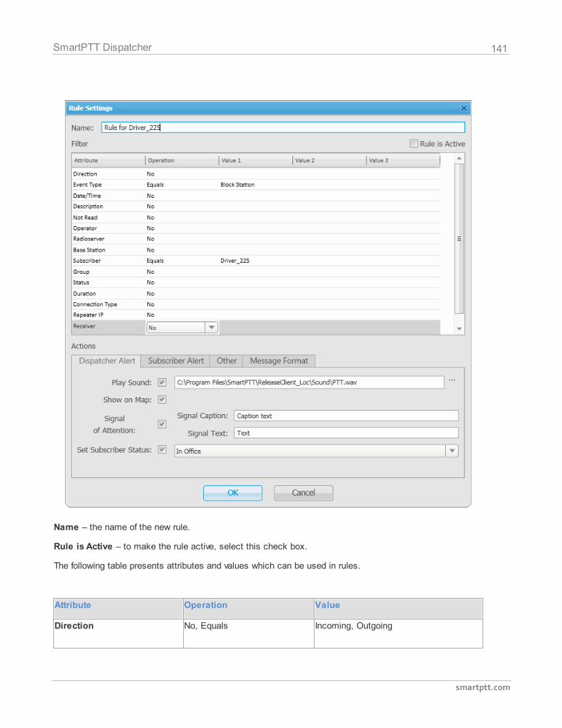
141
smartptt.com
SmartPTT Dispatcher
Name – the name of the new rule.
Rule is Active – to make the rule active, select this check box.
The following table presents attributes and values which can be used in rules.
Attribute Operation Value
Direction No, Equals Incoming, Outgoing
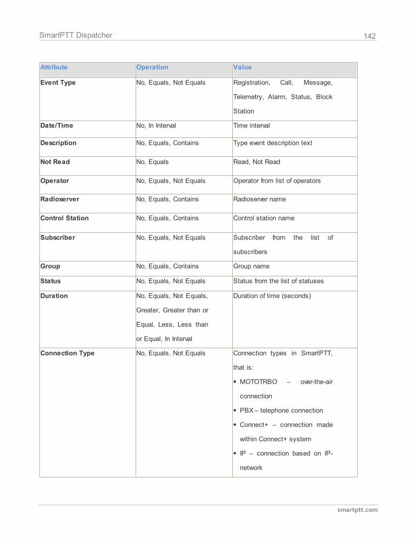
142
smartptt.com
SmartPTT Dispatcher
Attribute Operation Value
Event Type No, Equals, Not Equals Registration, Call, Message,
Telemetry, Alarm, Status, Block
Station
Date/Time No, In Interval Time interval
Description No, Equals, Contains Type event description text
Not Read No, Equals Read, Not Read
Operator No, Equals, Not Equals Operator from list of operators
Radioserver No, Equals, Contains Radioserver name
Control Station No, Equals, Contains Control station name
Subscriber No, Equals, Not Equals Subscriber from the list of
subscribers
Group No, Equals, Contains Group name
Status No, Equals, Not Equals Status from the list of statuses
Duration No, Equals, Not Equals,
Greater, Greater than or
Equal, Less, Less than
or Equal, In Interval
Duration of time (seconds)
Connection Type No, Equals, Not Equals Connection types in SmartPTT,
that is:
MOTOTRBO – over-the-air
connection
PBX – telephone connection
Connect+ – connection made
within Connect+ system
IP – connection based on IP-
network
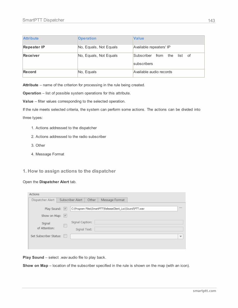
143
smartptt.com
SmartPTT Dispatcher
Attribute Operation Value
Repeater IP No, Equals, Not Equals Available repeaters' IP
Receiver No, Equals, Not Equals Subscriber from the list of
subscribers
Record No, Equals Available audio records
Attribute – name of the criterion for processing in the rule being created.
Operation – list of possible system operations for this attribute.
Value – filter values corresponding to the selected operation.
If the rule meets selected criteria, the system can perform some actions. The actions can be divided into
three types:
1. Actions addressed to the dispatcher
2. Actions addressed to the radio subscriber
3. Other
4. Message Format
1. How to assign actions to the dispatcher
Open the Dispatcher Alert tab.
Play Sound – select .wav audio file to play back.
Show on Map – location of the subscriber specified in the rule is shown on the map (with an icon).
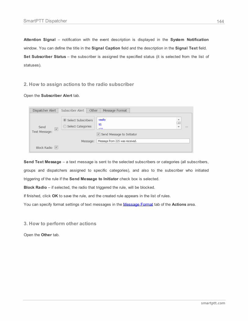
144
smartptt.com
SmartPTT Dispatcher
Attention Signal – notification with the event description is displayed in the System Notification
window. You can define the title in the Signal Caption field and the description in the Signal Text field.
Set Subscriber Status – the subscriber is assigned the specified status (it is selected from the list of
statuses).
2. How to assign actions to the radio subscriber
Open the Subscriber Alert tab.
Send Text Message – a text message is sent to the selected subscribers or categories (all subscribers,
groups and dispatchers assigned to specific categories), and also to the subscriber who initiated
triggering of the rule if the Send Message to Initiator check box is selected.
Block Radio – if selected, the radio that triggered the rule, will be blocked.
If finished, click OK to save the rule, and the created rule appears in the list of rules.
You can specify format settings of text messages in the Message Format tab of the Actions area.
3. How to perform other actions
Open the Other tab.
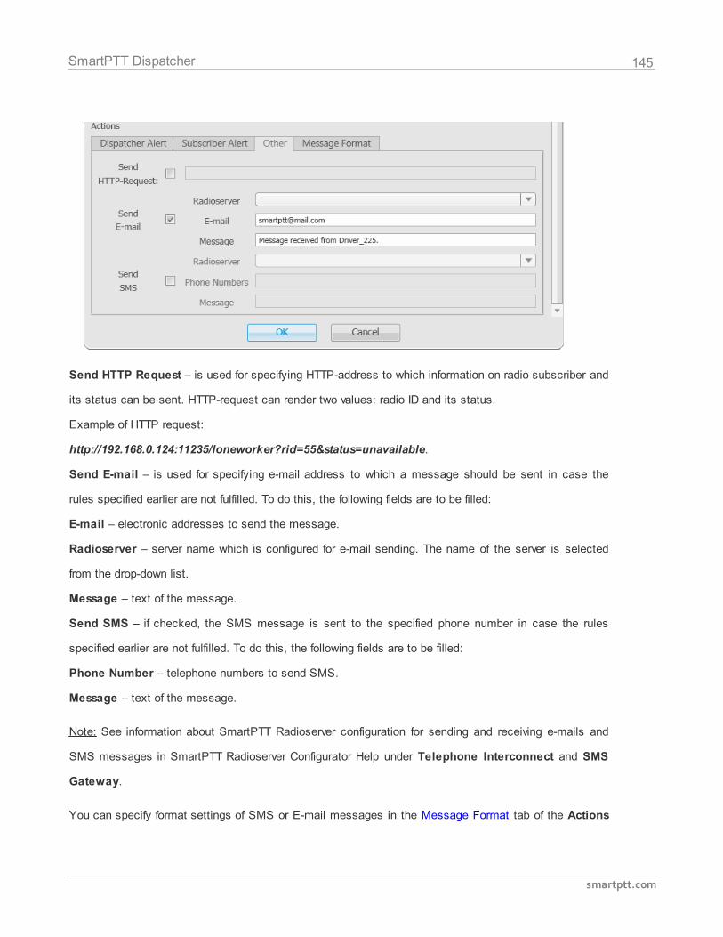
145
smartptt.com
SmartPTT Dispatcher
Send HTTP Request – is used for specifying HTTP-address to which information on radio subscriber and
its status can be sent. HTTP-request can render two values: radio ID and its status.
Example of HTTP request:
http://192.168.0.124:11235/loneworker?rid=55&status=unavailable.
Send E-mail – is used for specifying e-mail address to which a message should be sent in case the
rules specified earlier are not fulfilled. To do this, the following fields are to be filled:
E-mail – electronic addresses to send the message.
Radioserver – server name which is configured for e-mail sending. The name of the server is selected
from the drop-down list.
Message – text of the message.
Send SMS – if checked, the SMS message is sent to the specified phone number in case the rules
specified earlier are not fulfilled. To do this, the following fields are to be filled:
Phone Number – telephone numbers to send SMS.
Message – text of the message.
Note: See information about SmartPTT Radioserver configuration for sending and receiving e-mails and
SMS messages in SmartPTT Radioserver Configurator Help under Telephone Interconnect and SMS
Gateway.
You can specify format settings of SMS or E-mail messages in the Message Format tab of the Actions
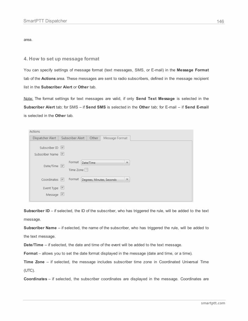
146
smartptt.com
SmartPTT Dispatcher
area.
4. How to set up message format
You can specify settings of message format (text messages, SMS, or E-mail) in the Message Format
tab of the Actions area. These messages are sent to radio subscribers, defined in the message recipient
list in the Subscriber Alert or Other tab.
Note: The format settings for text messages are valid, if only Send Text Message is selected in the
Subscriber Alert tab; for SMS – if Send SMS is selected in the Other tab; for E-mail – if Send E-mail
is selected in the Other tab.
Subscriber ID – if selected, the ID of the subscriber, who has triggered the rule, will be added to the text
message.
Subscriber Name – if selected, the name of the subscriber, who has triggered the rule, will be added to
the text message.
Date/Time – if selected, the date and time of the event will be added to the text message.
Format – allows you to set the date format displayed in the message (date and time, or a time).
Time Zone – if selected, the message includes subscriber time zone in Coordinated Universal Time
(UTC).
Coordinates – if selected, the subscriber coordinates are displayed in the message. Coordinates are
147
smartptt.com
SmartPTT Dispatcher
relevant to the moment, when the rule was initiated.
Event Type – if selected, the message includes the type of the event, which triggered the rule.
Message – if selected, the text message, specified in the Subscriber Alert tab, the Message field, will
be added to the message.
In the settings by default, only the Message field is selected.
2.8.20 GPS Rules
You can set response rules to GPS events in the SmartPTT Dispatcher application. GPS event is the
receipt of information about a subscriber’s GPS coordinates (or absence of such information during the
specified time interval).
To set GPS rules, expand the Settings menu in the main menu of the SmartPTT Dispatcher window and
click GPS Rules. The configuration window is displayed. It is used to set and configure a list of response
rules applied to GPS events which occur during the system operation.
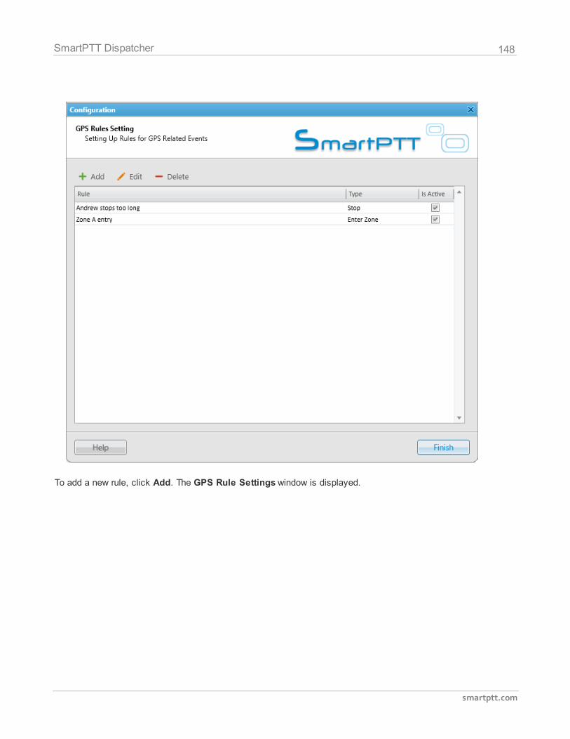
148
smartptt.com
SmartPTT Dispatcher
To add a new rule, click Add. The GPS Rule Settings window is displayed.
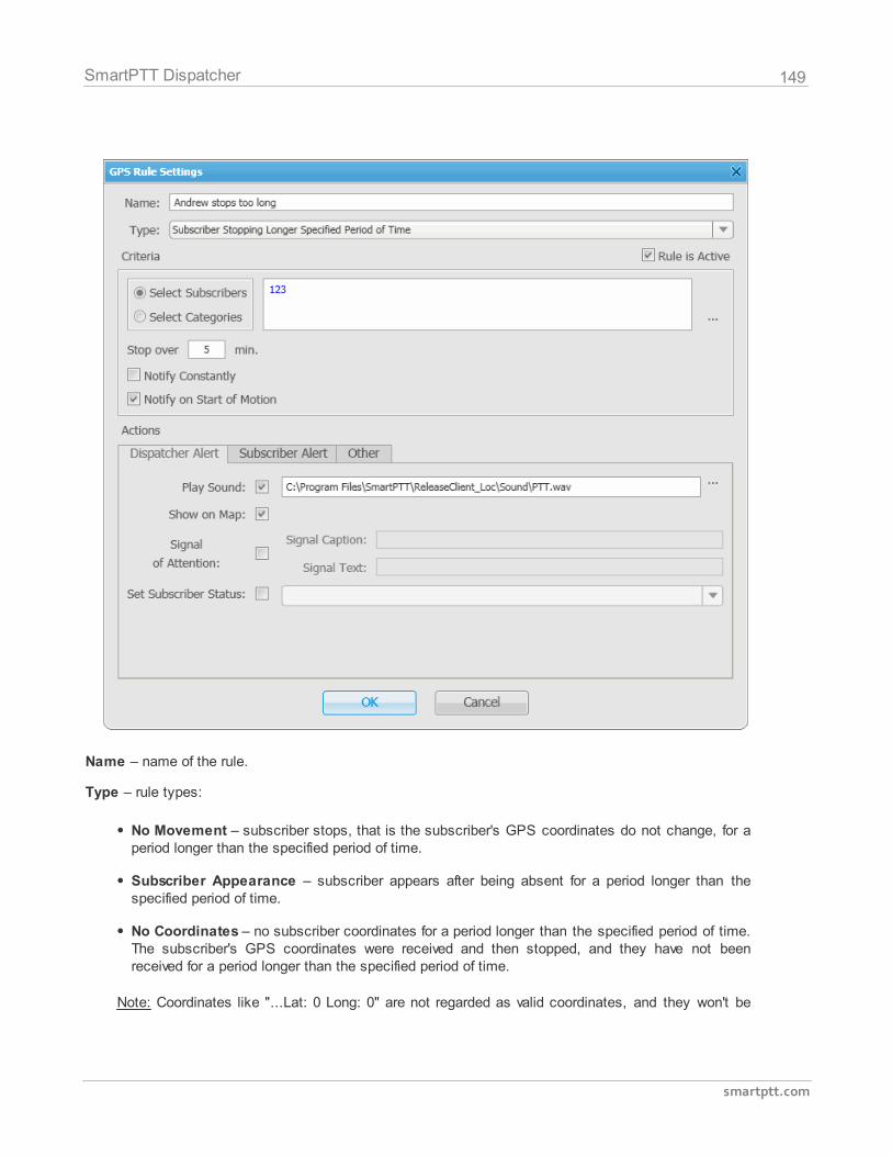
149
smartptt.com
SmartPTT Dispatcher
Name – name of the rule.
Type – rule types:
No Movement – subscriber stops, that is the subscriber's GPS coordinates do not change, for aperiod longer than the specified period of time.
Subscriber Appearance – subscriber appears after being absent for a period longer than thespecified period of time.
No Coordinates – no subscriber coordinates for a period longer than the specified period of time.The subscriber's GPS coordinates were received and then stopped, and they have not beenreceived for a period longer than the specified period of time.
Note: Coordinates like "...Lat: 0 Long: 0" are not regarded as valid coordinates, and they won't be
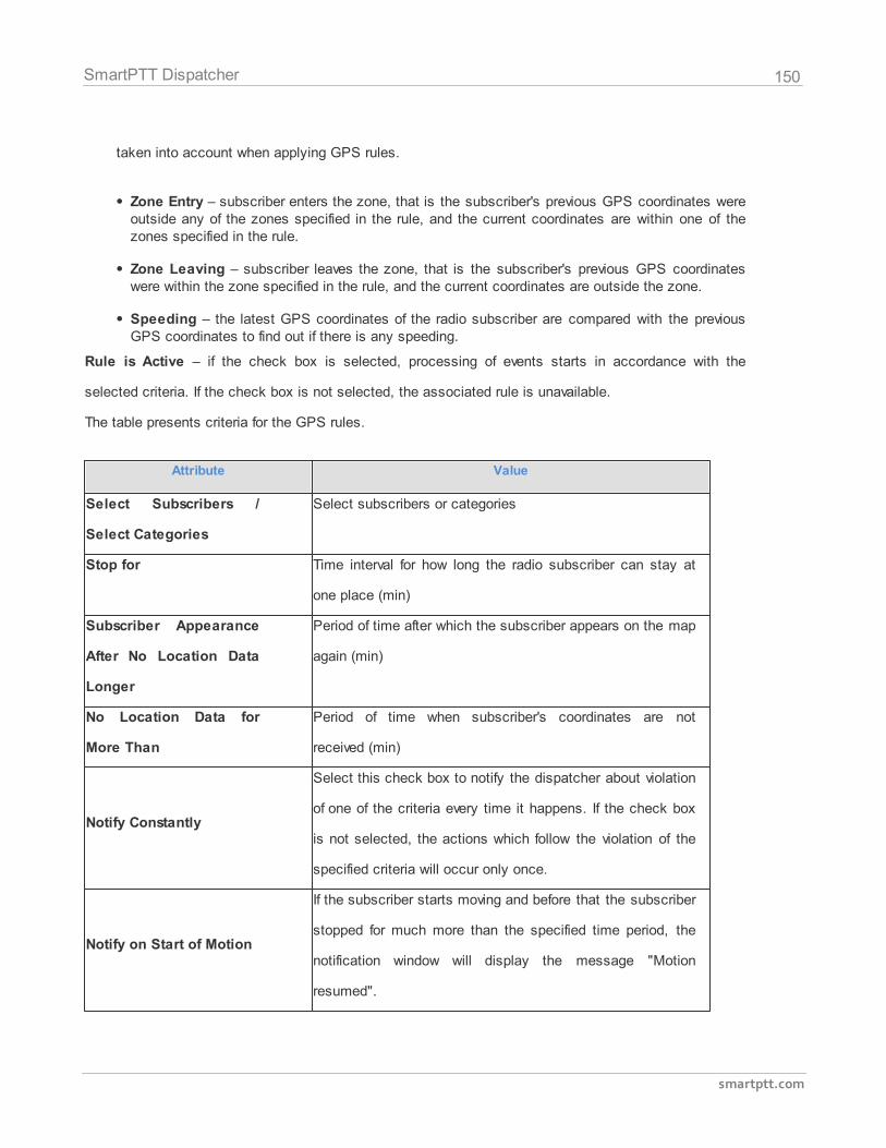
150
smartptt.com
SmartPTT Dispatcher
taken into account when applying GPS rules.
Zone Entry – subscriber enters the zone, that is the subscriber's previous GPS coordinates wereoutside any of the zones specified in the rule, and the current coordinates are within one of thezones specified in the rule.
Zone Leaving – subscriber leaves the zone, that is the subscriber's previous GPS coordinateswere within the zone specified in the rule, and the current coordinates are outside the zone.
Speeding – the latest GPS coordinates of the radio subscriber are compared with the previousGPS coordinates to find out if there is any speeding.
Rule is Active – if the check box is selected, processing of events starts in accordance with the
selected criteria. If the check box is not selected, the associated rule is unavailable.
The table presents criteria for the GPS rules.
Attribute Value
Select Subscribers /
Select Categories
Select subscribers or categories
Stop for Time interval for how long the radio subscriber can stay at
one place (min)
Subscriber Appearance
After No Location Data
Longer
Period of time after which the subscriber appears on the map
again (min)
No Location Data for
More Than
Period of time when subscriber's coordinates are not
received (min)
Notify Constantly
Select this check box to notify the dispatcher about violation
of one of the criteria every time it happens. If the check box
is not selected, the actions which follow the violation of the
specified criteria will occur only once.
Notify on Start of Motion
If the subscriber starts moving and before that the subscriber
stopped for much more than the specified time period, the
notification window will display the message "Motion
resumed".
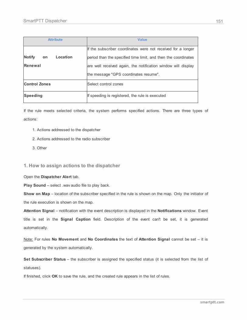
151
smartptt.com
SmartPTT Dispatcher
Attribute Value
Notify on Location
Renewal
If the subscriber coordinates were not received for a longer
period than the specified time limit, and then the coordinates
are well received again, the notification window will display
the message "GPS coordinates resume".
Control Zones Select control zones
Speeding If speeding is registered, the rule is executed
If the rule meets selected criteria, the system performs specified actions. There are three types of
actions:
1. Actions addressed to the dispatcher
2. Actions addressed to the radio subscriber
3. Other
1. How to assign actions to the dispatcher
Open the Dispatcher Alert tab.
Play Sound – select .wav audio file to play back.
Show on Map – location of the subscriber specified in the rule is shown on the map. Only the initiator of
the rule execution is shown on the map.
Attention Signal – notification with the event description is displayed in the Notifications window. Event
title is set in the Signal Caption field. Description of the event can't be set, it is generated
automatically.
Note: For rules No Movement and No Coordinates the text of Attention Signal cannot be set – it is
generated by the system automatically.
Set Subscriber Status – the subscriber is assigned the specified status (it is selected from the list of
statuses).
If finished, click OK to save the rule, and the created rule appears in the list of rules.
152
smartptt.com
SmartPTT Dispatcher
2. How to assign actions to the radio subscriber
Open the Subscriber Alert tab.
Send Text Message – a text message is sent to the selected subscribers or categories (all subscribers,
groups and dispatchers assigned to specific categories), and also to the subscriber who initiated
triggering of the rule if the Send Message to Initiator check box is selected.
If finished, click OK to save the rule, and the created rule appears in the list of rules.
3. How to perform other actions
Open the Other tab.
Send HTTP Request – is used for specifying HTTP-address to which information on radio subscriber and
its status can be sent. HTTP-request can render two values: radio ID and its status.
Example of HTTP request: http://192.168.0.124:11235/loneworker?rid=55&status=unavailable.
Send E-mail – is used for specifying e-mail address to which a message should be sent in case the
rules specified earlier are not fulfilled. To do this, the following fields are to be filled:
E-mail – electronic addresses to send the message.
Radioserver – server name which is configured for e-mail sending. The name of the server is selected
from the drop-down list.
Message – text of the message.
Send SMS – if checked, the SMS message is sent to the specified phone number in case the rules
specified earlier are not fulfilled. To do this, the following fields are to be filled:
Phone Number – telephone numbers to send SMS.
Message – text of the message.
Note: See information about SmartPTT Radioserver configuration for sending and receiving e-mails and
SMS messages in SmartPTT Radioserver Configurator Help under Telephone Interconnect and SMS
Gateway.
To edit an existing rule, select its entry in the list of rules and click Edit. Edit the rule and click OK – the
153
smartptt.com
SmartPTT Dispatcher
changes will be saved.
To delete a rule, select it in the list of rules and click Delete.
2.8.21 Lone Worker Rules
SmartPTT Dispatcher supports the Lone Worker mode for radio subscribers.
When a subscriber is set as working in the Lone Worker mode, SmartPTT automatically tracks the
following conditions:
No calls from the subscriber during specified period of time.
No GPS location from the subscriber during specified period of time.
No movement of the subscriber during specified period of time.
When some of the specified conditions triggers, SmartPTT Dispatcher executes the actions defined by
the settings.
To define the Lone Worker rules, expand the Settings menu in the Main Menu bar of the SmartPTT
Dispatcher window and click Lone Worker Rules. At that, the window for creation and/or editing Lone
Worker Profiles opens.
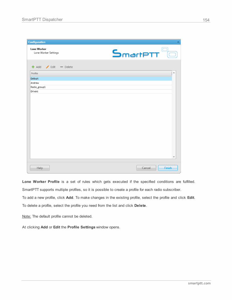
154
smartptt.com
SmartPTT Dispatcher
Lone Worker Profile is a set of rules which gets executed if the specified conditions are fulfilled.
SmartPTT supports multiple profiles, so it is possible to create a profile for each radio subscriber.
To add a new profile, click Add. To make changes in the existing profile, select the profile and click Edit.
To delete a profile, select the profile you need from the list and click Delete.
Note: The default profile cannot be deleted.
At clicking Add or Edit the Profile Settings window opens.
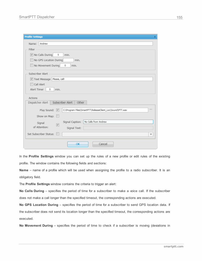
155
smartptt.com
SmartPTT Dispatcher
In the Profile Settings window you can set up the rules of a new profile or edit rules of the existing
profile. The window contains the following fields and sections:
Name – name of a profile which will be used when assigning the profile to a radio subscriber. It is an
obligatory field.
The Profile Settings window contains the criteria to trigger an alert:
No Calls During – specifies the period of time for a subscriber to make a voice call. If the subscriber
does not make a call longer than the specified timeout, the corresponding actions are executed.
No GPS Location During – specifies the period of time for a subscriber to send GPS location data. If
the subscriber does not send its location longer than the specified timeout, the corresponding actions are
executed.
No Movement During – specifies the period of time to check if a subscriber is moving (deviations in
156
smartptt.com
SmartPTT Dispatcher
range of 5 meters are ignored). If the subscriber does not move longer than the specified timeout, the
corresponding actions are executed.
The Subscriber Alert area:
Text Message – when the event described by one of the rules above occurs, the text message is sent to
the lone worker.
Call Alert – when the event described by one of the rules above occurs, a Call Alert is sent to the lone
worker.
Alert Timer – specifies the time period for a subscriber to make a call, to send GPS coordinates or to
move after Subscriber Alert took place.
If the Alert Timer has expired but the subscriber did not perform certain actions or if the Alert Timer
equals 0, the system executes the actions specified in the Actions area.
There are three tabs in the Actions area:
1. Actions addressed to the dispatcher
2. Actions addressed to the radio subscriber
3. Other
1. How to assign actions to the dispatcher
Open the Dispatcher Alert tab. The Dispatcher Alert tab allows specifying actions which will be
addressed to the dispatcher.
Play Sound – uploads a sound file in .wav format which will play to the dispatcher after the rules set
above were not fulfilled.
Show on Map – subscriber radio will be shown on map using the latest GPS coordinates received from
the radio station.
Attention Signal – notification with the event description is displayed in the Notifications window. The
event title is set in the Signal Caption field. Description of the event can't be set, it is generated
automatically.
Set Subscriber Status – set status for the subscriber from the list of available statuses.
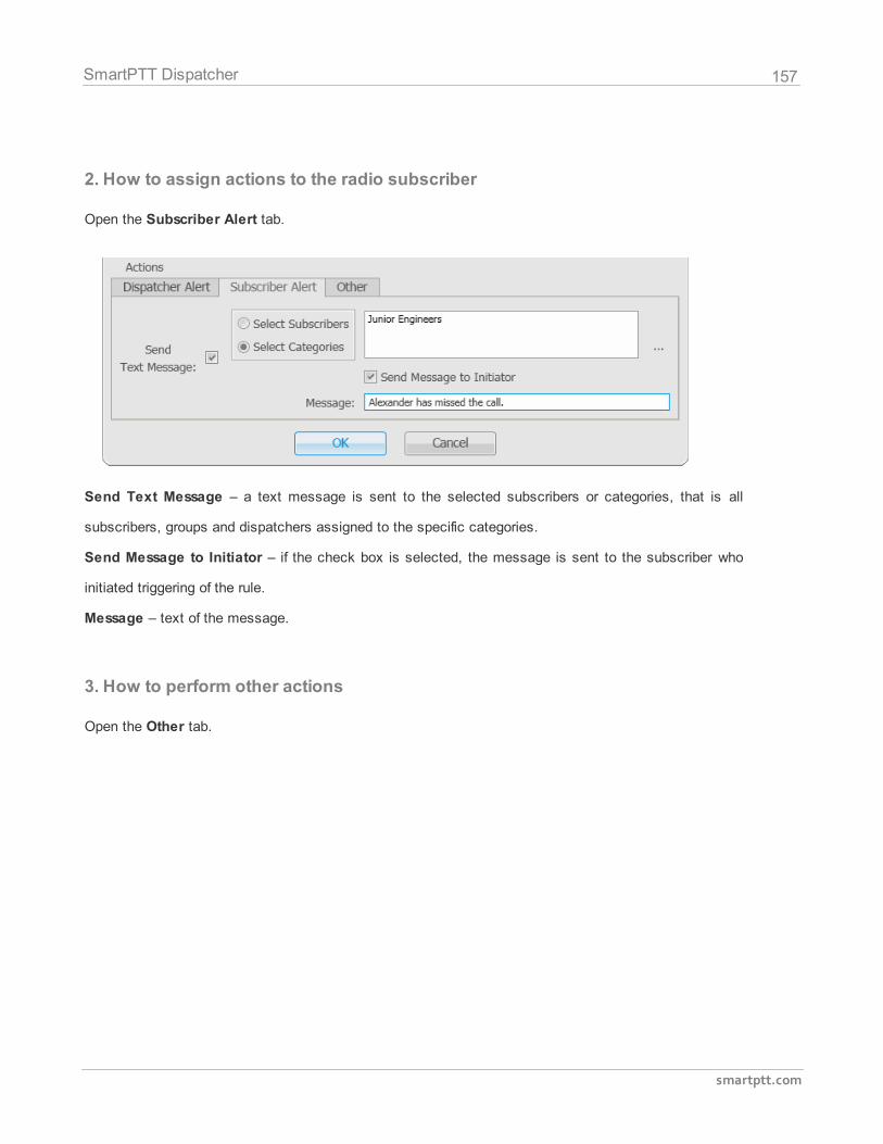
157
smartptt.com
SmartPTT Dispatcher
2. How to assign actions to the radio subscriber
Open the Subscriber Alert tab.
Send Text Message – a text message is sent to the selected subscribers or categories, that is all
subscribers, groups and dispatchers assigned to the specific categories.
Send Message to Initiator – if the check box is selected, the message is sent to the subscriber who
initiated triggering of the rule.
Message – text of the message.
3. How to perform other actions
Open the Other tab.
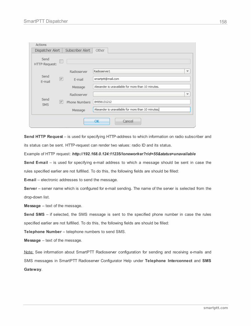
158
smartptt.com
SmartPTT Dispatcher
Send HTTP Request – is used for specifying HTTP-address to which information on radio subscriber and
its status can be sent. HTTP-request can render two values: radio ID and its status.
Example of HTTP request: http://192.168.0.124:11235/loneworker?rid=55&status=unavailable
Send E-mail – is used for specifying e-mail address to which a message should be sent in case the
rules specified earlier are not fulfilled. To do this, the following fields are should be filled:
E-mail – electronic addresses to send the message.
Server – server name which is configured for e-mail sending. The name of the server is selected from the
drop-down list.
Message – text of the message.
Send SMS – if selected, the SMS message is sent to the specified phone number in case the rules
specified earlier are not fulfilled. To do this, the following fields are should be filled:
Telephone Number – telephone numbers to send SMS.
Message – text of the message.
Note: See information about SmartPTT Radioserver configuration for sending and receiving e-mails and
SMS messages in SmartPTT Radioserver Configurator Help under Telephone Interconnect and SMS
Gateway.
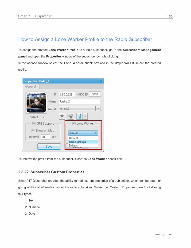
159
smartptt.com
SmartPTT Dispatcher
How to Assign a Lone Worker Profile to the Radio Subscriber
To assign the created Lone Worker Profile to a radio subscriber, go to the Subscribers Management
panel and open the Properties window of the subscriber by right-clicking.
In the opened window select the Lone Worker check box and in the drop-down list select the created
profile.
To remove the profile from the subscriber, clear the Lone Worker check box.
2.8.22 Subscriber Custom Properties
SmartPTT Dispatcher provides the ability to add custom properties of a subscriber, which can be used for
giving additional information about the radio subscriber. Subscriber Custom Properties have the following
four types:
1. Text
2. Numeric
3. Date
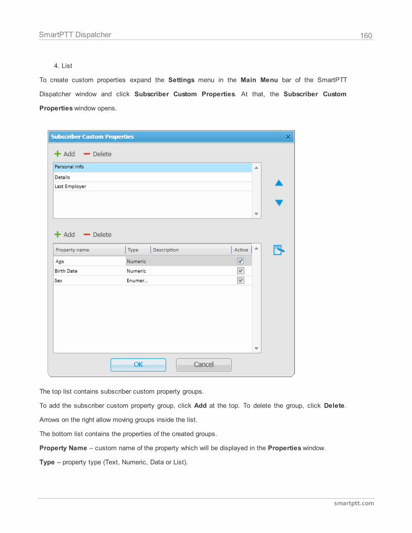
160
smartptt.com
SmartPTT Dispatcher
4. List
To create custom properties expand the Settings menu in the Main Menu bar of the SmartPTT
Dispatcher window and click Subscriber Custom Properties. At that, the Subscriber Custom
Properties window opens.
The top list contains subscriber custom property groups.
To add the subscriber custom property group, click Add at the top. To delete the group, click Delete.
Arrows on the right allow moving groups inside the list.
The bottom list contains the properties of the created groups.
Property Name – custom name of the property which will be displayed in the Properties window.
Type – property type (Text, Numeric, Data or List).
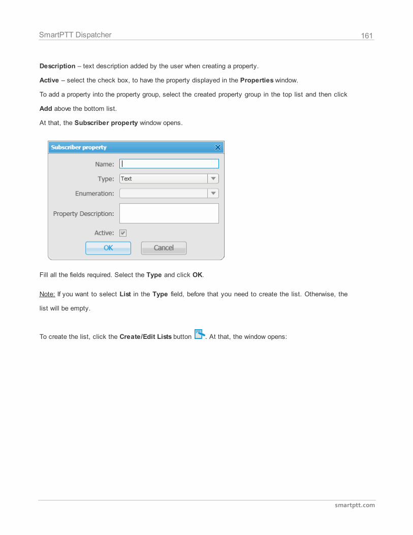
161
smartptt.com
SmartPTT Dispatcher
Description – text description added by the user when creating a property.
Active – select the check box, to have the property displayed in the Properties window.
To add a property into the property group, select the created property group in the top list and then click
Add above the bottom list.
At that, the Subscriber property window opens.
Fill all the fields required. Select the Type and click OK.
Note: If you want to select List in the Type field, before that you need to create the list. Otherwise, the
list will be empty.
To create the list, click the Create/Edit Lists button . At that, the window opens:
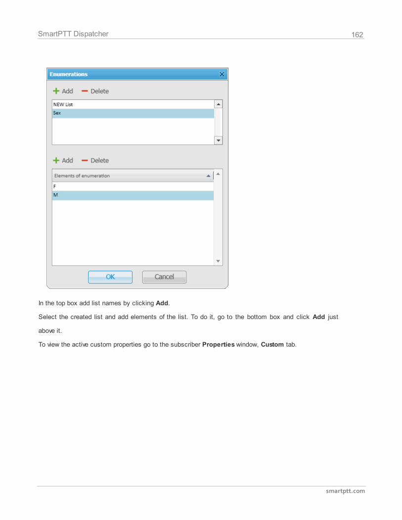
162
smartptt.com
SmartPTT Dispatcher
In the top box add list names by clicking Add.
Select the created list and add elements of the list. To do it, go to the bottom box and click Add just
above it.
To view the active custom properties go to the subscriber Properties window, Custom tab.

163
smartptt.com
SmartPTT Dispatcher
2.8.23 Custom Consoles
Custom Consoles are implemented as visual panels, designed in SmartPTT Dispatcher to manage
specific subscribers, groups or control stations. The embedded console designer allows creating panels
containing visual buttons of variable sizes and placement assigned to corresponding subscribers or
groups. Using visual control buttons the dispatcher can make voice calls, have quick access to
subscriber properties or the Call Window.
To configure custom consoles, expand the Settings menu in the Main Menu bar of the SmartPTT
Dispatcher window and click Custom Consoles. At that, the Custom Consoles window opens.
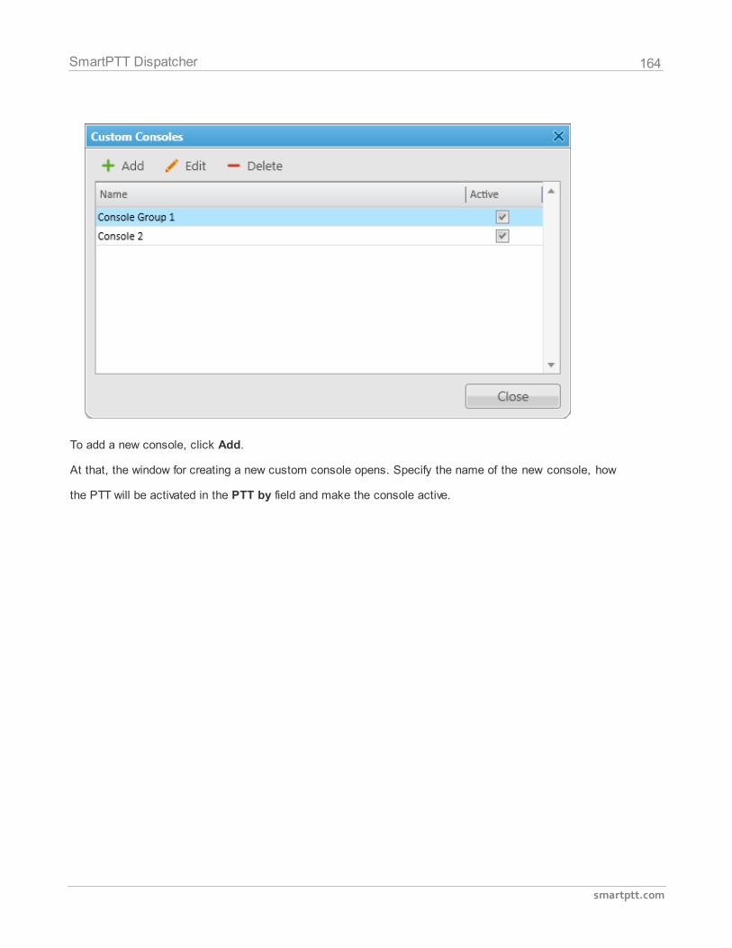
164
smartptt.com
SmartPTT Dispatcher
To add a new console, click Add.
At that, the window for creating a new custom console opens. Specify the name of the new console, how
the PTT will be activated in the PTT by field and make the console active.
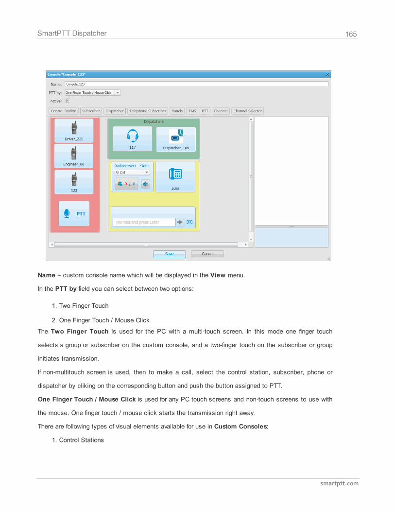
165
smartptt.com
SmartPTT Dispatcher
Name – custom console name which will be displayed in the View menu.
In the PTT by field you can select between two options:
1. Two Finger Touch
2. One Finger Touch / Mouse Click
The Two Finger Touch is used for the PC with a multi-touch screen. In this mode one finger touch
selects a group or subscriber on the custom console, and a two-finger touch on the subscriber or group
initiates transmission.
If non-multitouch screen is used, then to make a call, select the control station, subscriber, phone or
dispatcher by cliking on the corresponding button and push the button assigned to PTT.
One Finger Touch / Mouse Click is used for any PC touch screens and non-touch screens to use with
the mouse. One finger touch / mouse click starts the transmission right away.
There are following types of visual elements available for use in Custom Consoles:
1. Control Stations
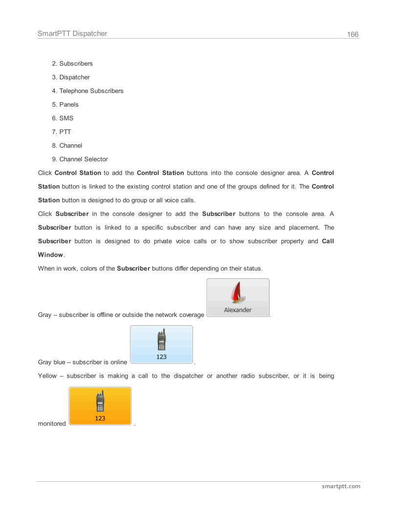
166
smartptt.com
SmartPTT Dispatcher
2. Subscribers
3. Dispatcher
4. Telephone Subscribers
5. Panels
6. SMS
7. PTT
8. Channel
9. Channel Selector
Click Control Station to add the Control Station buttons into the console designer area. A Control
Station button is linked to the existing control station and one of the groups defined for it. The Control
Station button is designed to do group or all voice calls.
Click Subscriber in the console designer to add the Subscriber buttons to the console area. A
Subscriber button is linked to a specific subscriber and can have any size and placement. The
Subscriber button is designed to do private voice calls or to show subscriber property and Call
Window.
When in work, colors of the Subscriber buttons differ depending on their status.
Gray – subscriber is offline or outside the network coverage .
Gray blue – subscriber is online .
Yellow – subscriber is making a call to the dispatcher or another radio subscriber, or it is being
monitored .
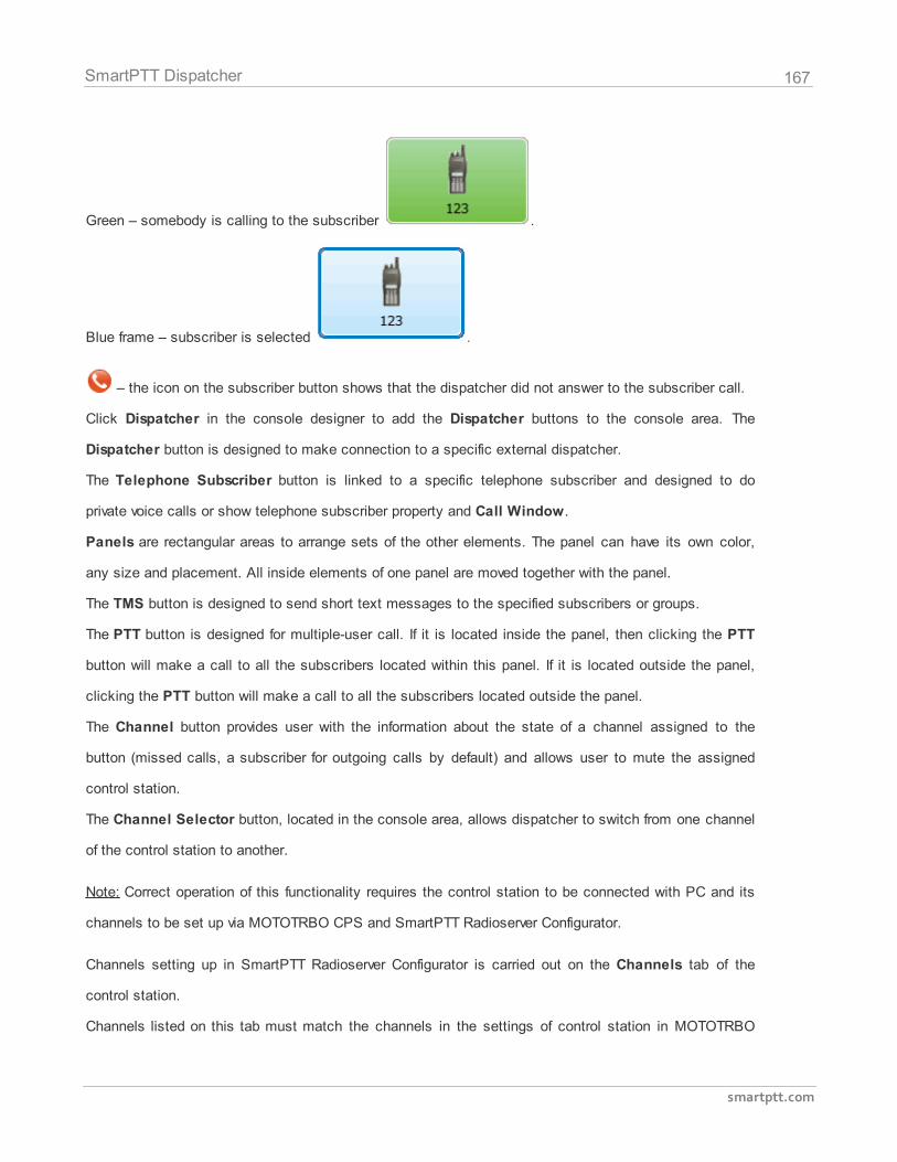
167
smartptt.com
SmartPTT Dispatcher
Green – somebody is calling to the subscriber .
Blue frame – subscriber is selected .
– the icon on the subscriber button shows that the dispatcher did not answer to the subscriber call.
Click Dispatcher in the console designer to add the Dispatcher buttons to the console area. The
Dispatcher button is designed to make connection to a specific external dispatcher.
The Telephone Subscriber button is linked to a specific telephone subscriber and designed to do
private voice calls or show telephone subscriber property and Call Window.
Panels are rectangular areas to arrange sets of the other elements. The panel can have its own color,
any size and placement. All inside elements of one panel are moved together with the panel.
The TMS button is designed to send short text messages to the specified subscribers or groups.
The PTT button is designed for multiple-user call. If it is located inside the panel, then clicking the PTT
button will make a call to all the subscribers located within this panel. If it is located outside the panel,
clicking the PTT button will make a call to all the subscribers located outside the panel.
The Channel button provides user with the information about the state of a channel assigned to the
button (missed calls, a subscriber for outgoing calls by default) and allows user to mute the assigned
control station.
The Channel Selector button, located in the console area, allows dispatcher to switch from one channel
of the control station to another.
Note: Correct operation of this functionality requires the control station to be connected with PC and its
channels to be set up via MOTOTRBO CPS and SmartPTT Radioserver Configurator.
Channels setting up in SmartPTT Radioserver Configurator is carried out on the Channels tab of the
control station.
Channels listed on this tab must match the channels in the settings of control station in MOTOTRBO
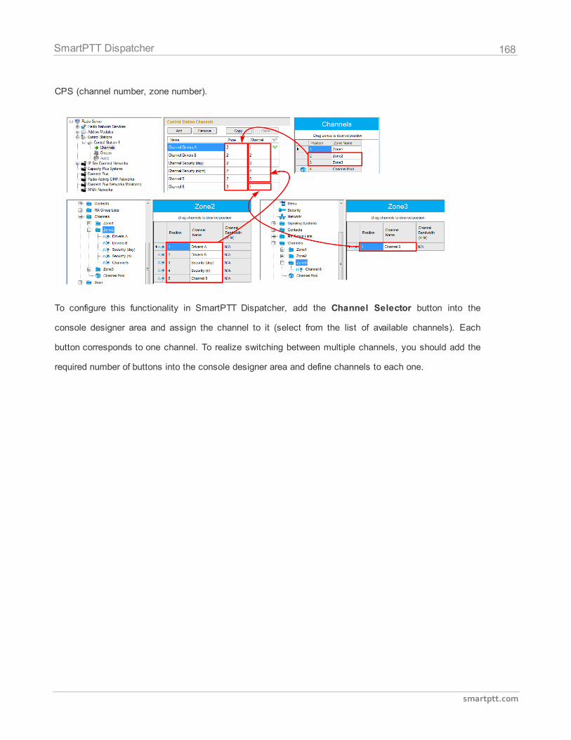
168
smartptt.com
SmartPTT Dispatcher
CPS (channel number, zone number).
To configure this functionality in SmartPTT Dispatcher, add the Channel Selector button into the
console designer area and assign the channel to it (select from the list of available channels). Each
button corresponds to one channel. To realize switching between multiple channels, you should add the
required number of buttons into the console designer area and define channels to each one.
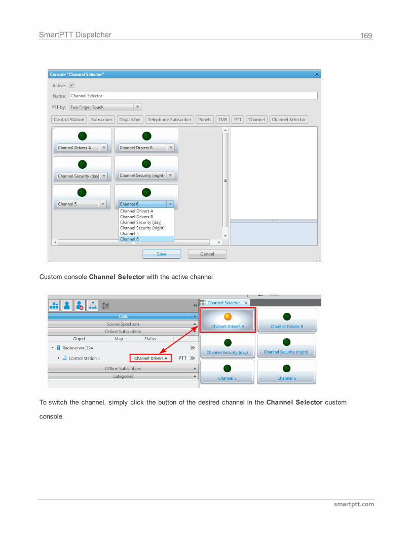
169
smartptt.com
SmartPTT Dispatcher
Custom console Channel Selector with the active channel
To switch the channel, simply click the button of the desired channel in the Channel Selector custom
console.
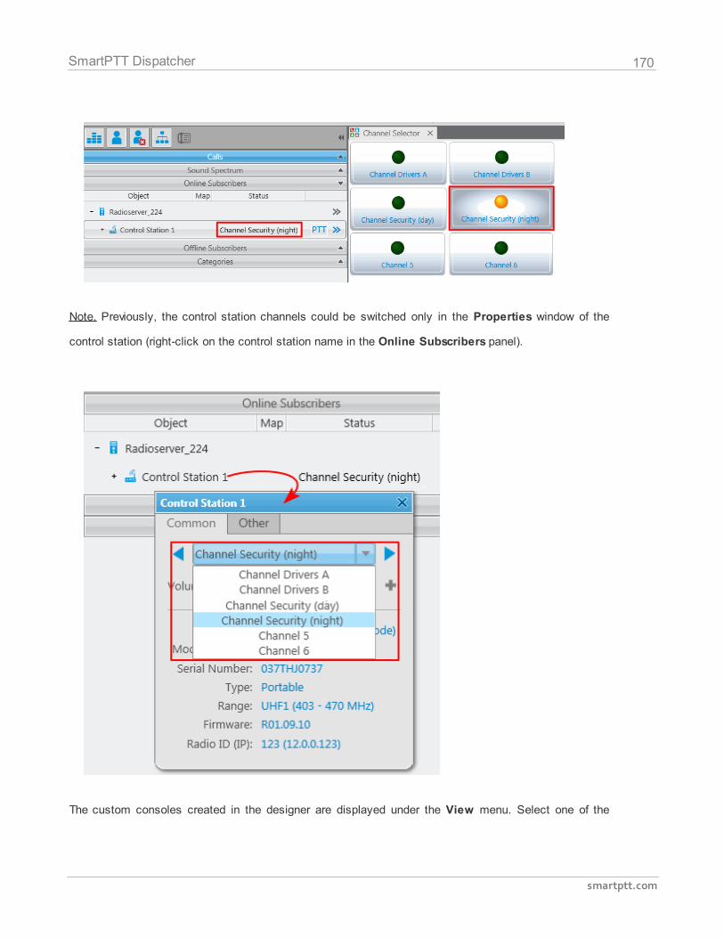
170
smartptt.com
SmartPTT Dispatcher
Note. Previously, the control station channels could be switched only in the Properties window of the
control station (right-click on the control station name in the Online Subscribers panel).
The custom consoles created in the designer are displayed under the View menu. Select one of the
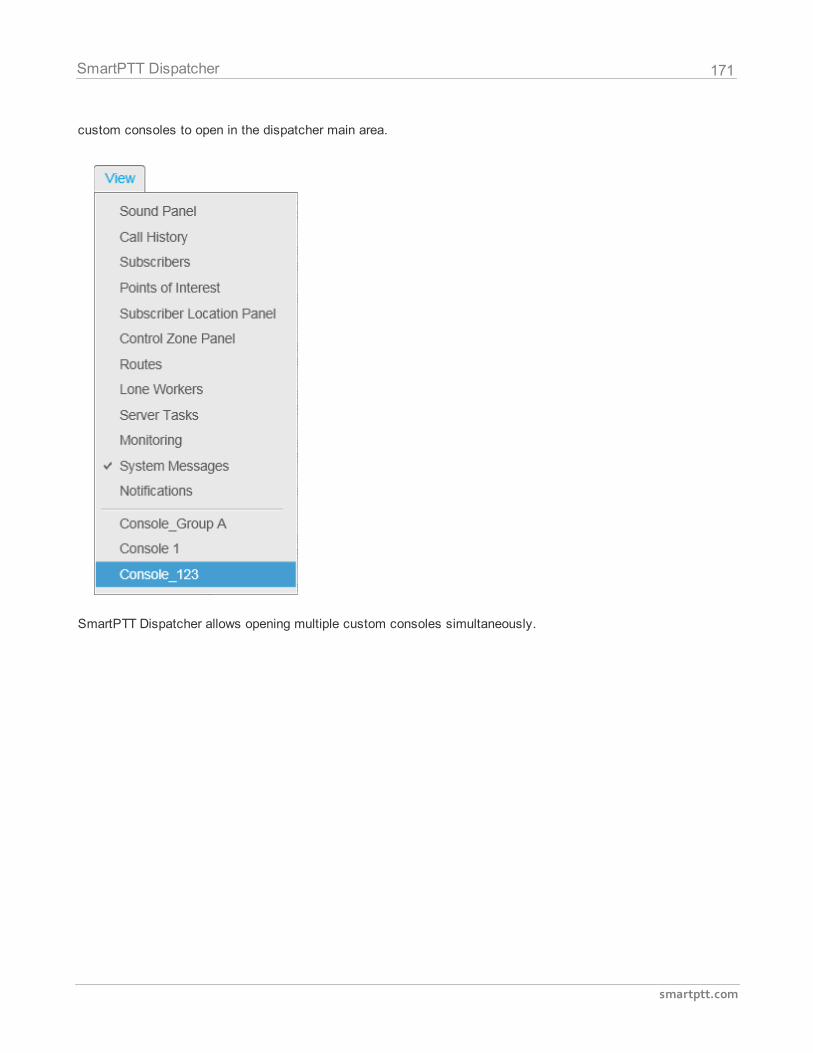
171
smartptt.com
SmartPTT Dispatcher
custom consoles to open in the dispatcher main area.
SmartPTT Dispatcher allows opening multiple custom consoles simultaneously.
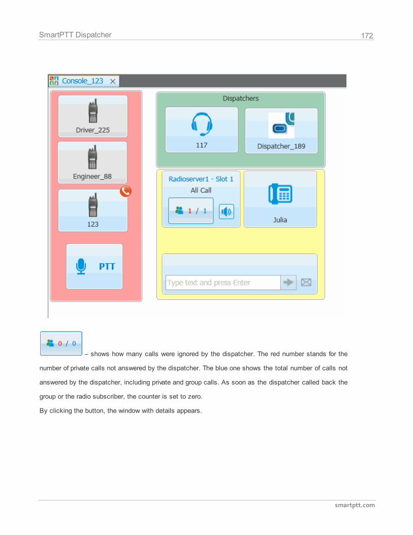
172
smartptt.com
SmartPTT Dispatcher
– shows how many calls were ignored by the dispatcher. The red number stands for the
number of private calls not answered by the dispatcher. The blue one shows the total number of calls not
answered by the dispatcher, including private and group calls. As soon as the dispatcher called back the
group or the radio subscriber, the counter is set to zero.
By clicking the button, the window with details appears.
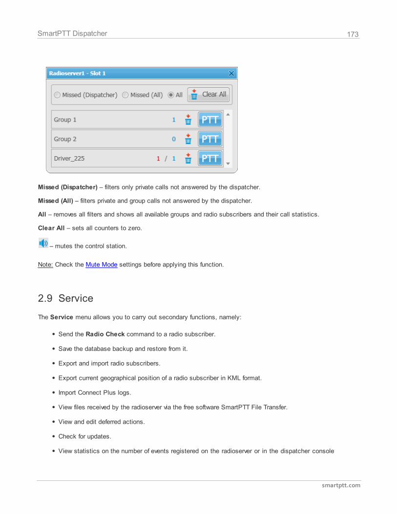
173
smartptt.com
SmartPTT Dispatcher
Missed (Dispatcher) – filters only private calls not answered by the dispatcher.
Missed (All) – filters private and group calls not answered by the dispatcher.
All – removes all filters and shows all available groups and radio subscribers and their call statistics.
Clear All – sets all counters to zero.
– mutes the control station.
Note: Check the Mute Mode settings before applying this function.
2.9 Service
The Service menu allows you to carry out secondary functions, namely:
Send the Radio Check command to a radio subscriber.
Save the database backup and restore from it.
Export and import radio subscribers.
Export current geographical position of a radio subscriber in KML format.
Import Connect Plus logs.
View files received by the radioserver via the free software SmartPTT File Transfer.
View and edit deferred actions.
Check for updates.
View statistics on the number of events registered on the radioserver or in the dispatcher console

174
smartptt.com
SmartPTT Dispatcher
and other information on the system.
2.9.1 Radio Check
The Radio Check function can be executed on the selected control stations available to the dispatcher.
The result of the Radio Check is displayed in the subscriber Call Window. It can be: "Subscriber is
available" or "Subscriber is unavailable".
To do Radio Check, expand the Service menu in the Main Menu bar of the SmartPTT Dispatcher
window and click Radio Check. At that, the Radio Check window opens.
Specify the IP of the subscriber radio. Select control stations which should be used to check the
subscriber availability and click Send.
Alternatively, Radio Check can be done from the Call Window or the Action List.
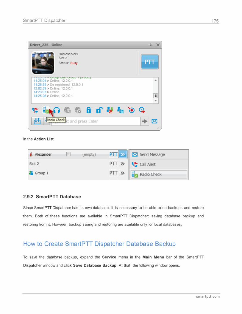
175
smartptt.com
SmartPTT Dispatcher
In the Action List:
2.9.2 SmartPTT Database
Since SmartPTT Dispatcher has its own database, it is necessary to be able to do backups and restore
them. Both of these functions are available in SmartPTT Dispatcher: saving database backup and
restoring from it. However, backup saving and restoring are available only for local databases.
How to Create SmartPTT Dispatcher Database Backup
To save the database backup, expand the Service menu in the Main Menu bar of the SmartPTT
Dispatcher window and click Save Database Backup. At that, the following window opens.
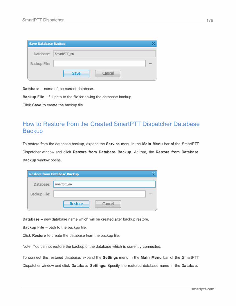
176
smartptt.com
SmartPTT Dispatcher
Database – name of the current database.
Backup File – full path to the file for saving the database backup.
Click Save to create the backup file.
How to Restore from the Created SmartPTT Dispatcher DatabaseBackup
To restore from the database backup, expand the Service menu in the Main Menu bar of the SmartPTT
Dispatcher window and click Restore from Database Backup. At that, the Restore from Database
Backup window opens.
Database – new database name which will be created after backup restore.
Backup File – path to the backup file.
Click Restore to create the database from the backup file.
Note: You cannot restore the backup of the database which is currently connected.
To connect the restored database, expand the Settings menu in the Main Menu bar of the SmartPTT
Dispatcher window and click Database Settings. Specify the restored database name in the Database
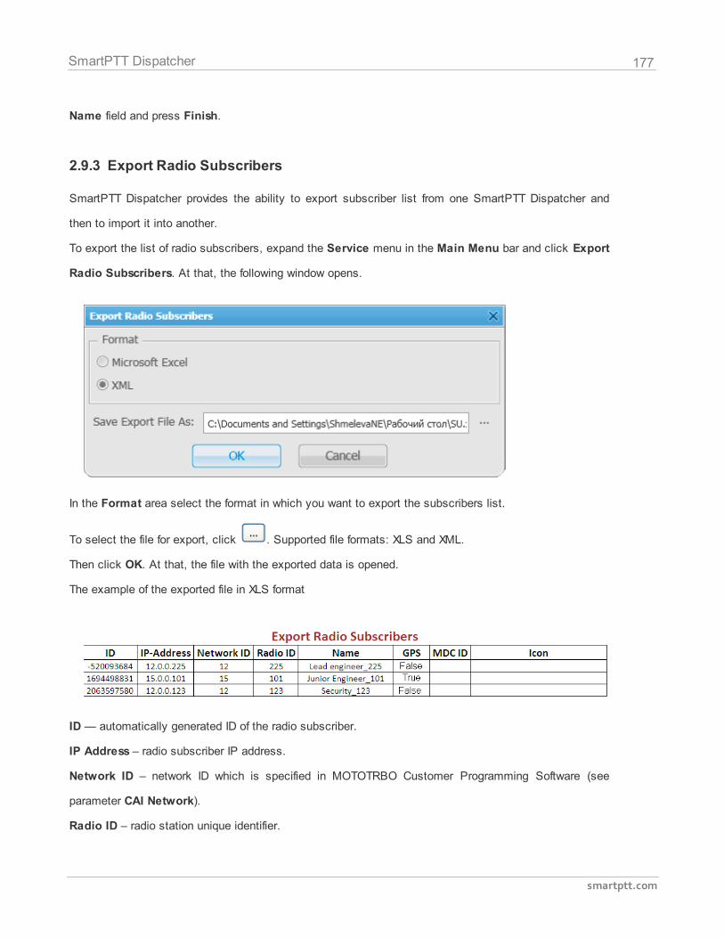
177
smartptt.com
SmartPTT Dispatcher
Name field and press Finish.
2.9.3 Export Radio Subscribers
SmartPTT Dispatcher provides the ability to export subscriber list from one SmartPTT Dispatcher and
then to import it into another.
To export the list of radio subscribers, expand the Service menu in the Main Menu bar and click Export
Radio Subscribers. At that, the following window opens.
In the Format area select the format in which you want to export the subscribers list.
To select the file for export, click . Supported file formats: XLS and XML.
Then click OK. At that, the file with the exported data is opened.
The example of the exported file in XLS format
ID — automatically generated ID of the radio subscriber.
IP Address – radio subscriber IP address.
Network ID – network ID which is specified in MOTOTRBO Customer Programming Software (see
parameter CAI Network).
Radio ID – radio station unique identifier.
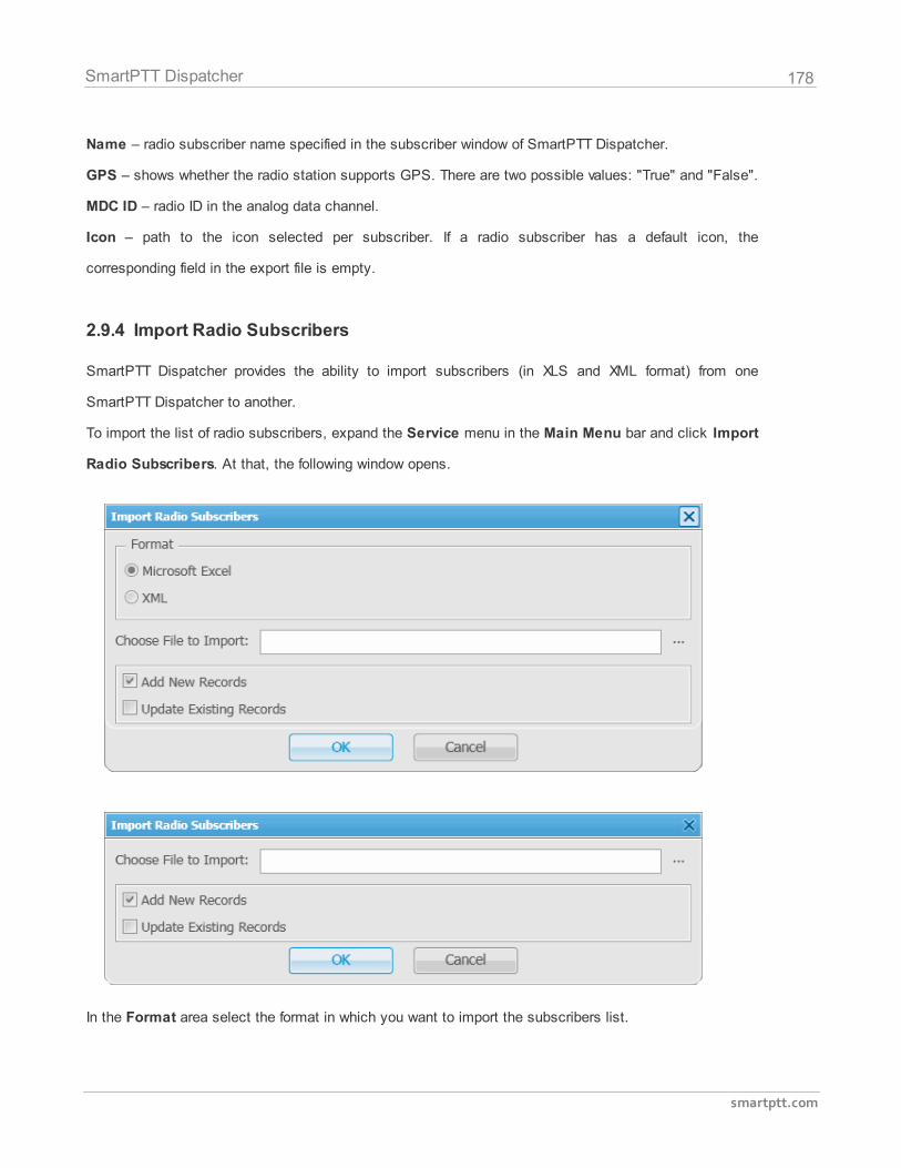
178
smartptt.com
SmartPTT Dispatcher
Name – radio subscriber name specified in the subscriber window of SmartPTT Dispatcher.
GPS – shows whether the radio station supports GPS. There are two possible values: "True" and "False".
MDC ID – radio ID in the analog data channel.
Icon – path to the icon selected per subscriber. If a radio subscriber has a default icon, the
corresponding field in the export file is empty.
2.9.4 Import Radio Subscribers
SmartPTT Dispatcher provides the ability to import subscribers (in XLS and XML format) from one
SmartPTT Dispatcher to another.
To import the list of radio subscribers, expand the Service menu in the Main Menu bar and click Import
Radio Subscribers. At that, the following window opens.
In the Format area select the format in which you want to import the subscribers list.
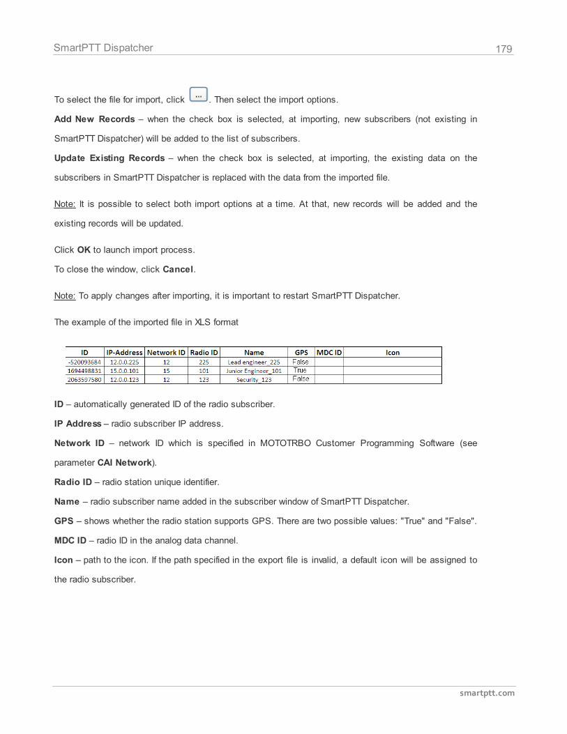
179
smartptt.com
SmartPTT Dispatcher
To select the file for import, click . Then select the import options.
Add New Records – when the check box is selected, at importing, new subscribers (not existing in
SmartPTT Dispatcher) will be added to the list of subscribers.
Update Existing Records – when the check box is selected, at importing, the existing data on the
subscribers in SmartPTT Dispatcher is replaced with the data from the imported file.
Note: It is possible to select both import options at a time. At that, new records will be added and the
existing records will be updated.
Click OK to launch import process.
To close the window, click Cancel.
Note: To apply changes after importing, it is important to restart SmartPTT Dispatcher.
The example of the imported file in XLS format
ID – automatically generated ID of the radio subscriber.
IP Address – radio subscriber IP address.
Network ID – network ID which is specified in MOTOTRBO Customer Programming Software (see
parameter CAI Network).
Radio ID – radio station unique identifier.
Name – radio subscriber name added in the subscriber window of SmartPTT Dispatcher.
GPS – shows whether the radio station supports GPS. There are two possible values: "True" and "False".
MDC ID – radio ID in the analog data channel.
Icon – path to the icon. If the path specified in the export file is invalid, a default icon will be assigned to
the radio subscriber.
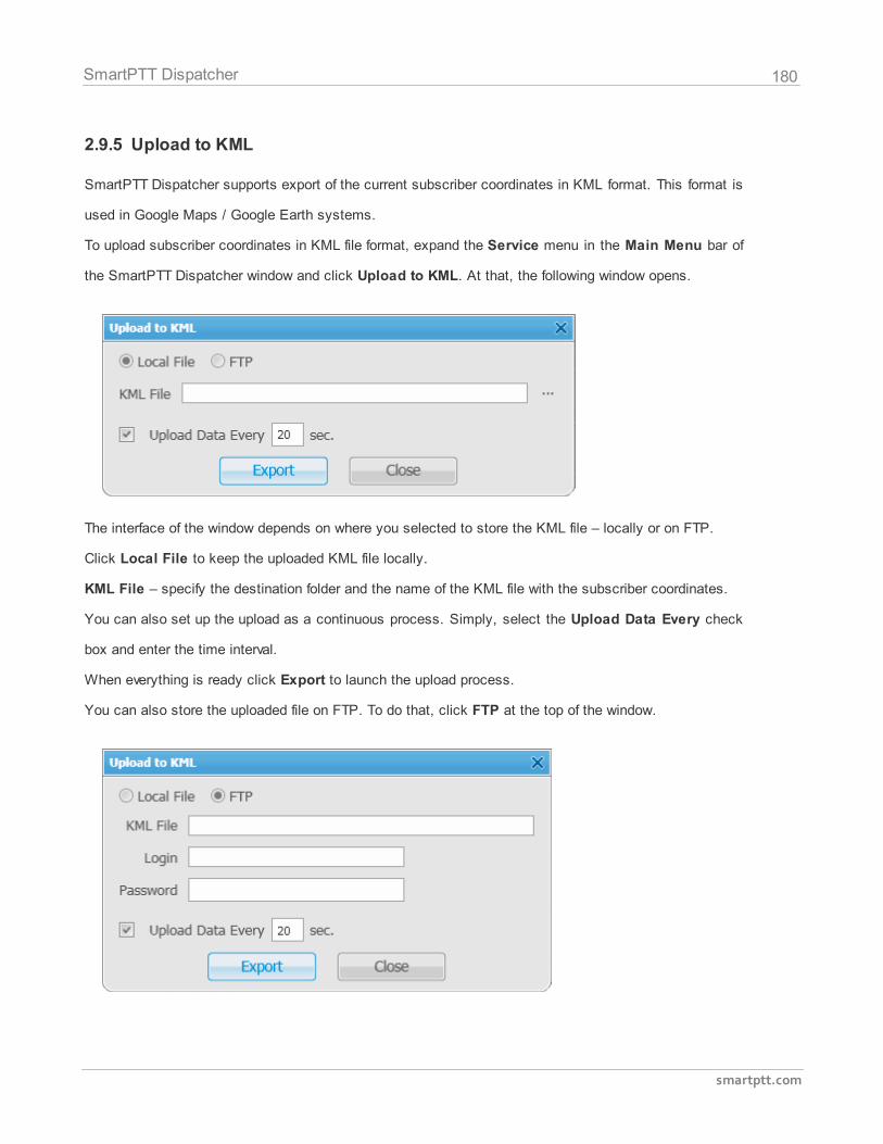
180
smartptt.com
SmartPTT Dispatcher
2.9.5 Upload to KML
SmartPTT Dispatcher supports export of the current subscriber coordinates in KML format. This format is
used in Google Maps / Google Earth systems.
To upload subscriber coordinates in KML file format, expand the Service menu in the Main Menu bar of
the SmartPTT Dispatcher window and click Upload to KML. At that, the following window opens.
The interface of the window depends on where you selected to store the KML file – locally or on FTP.
Click Local File to keep the uploaded KML file locally.
KML File – specify the destination folder and the name of the KML file with the subscriber coordinates.
You can also set up the upload as a continuous process. Simply, select the Upload Data Every check
box and enter the time interval.
When everything is ready click Export to launch the upload process.
You can also store the uploaded file on FTP. To do that, click FTP at the top of the window.
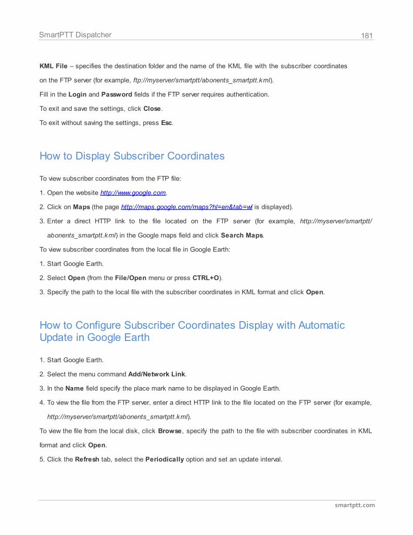
181
smartptt.com
SmartPTT Dispatcher
KML File – specifies the destination folder and the name of the KML file with the subscriber coordinates
on the FTP server (for example, ftp://myserver/smartptt/abonents_smartptt.kml).
Fill in the Login and Password fields if the FTP server requires authentication.
To exit and save the settings, click Close.
To exit without saving the settings, press Esc.
How to Display Subscriber Coordinates
To view subscriber coordinates from the FTP file:
1. Open the website http://www.google.com.
2. Click on Maps (the page http://maps.google.com/maps?hl=en&tab=wl is displayed).
3. Enter a direct HTTP link to the file located on the FTP server (for example, http://myserver/smartptt/
abonents_smartptt.kml) in the Google maps field and click Search Maps.
To view subscriber coordinates from the local file in Google Earth:
1. Start Google Earth.
2. Select Open (from the File/Open menu or press CTRL+O).
3. Specify the path to the local file with the subscriber coordinates in KML format and click Open.
How to Configure Subscriber Coordinates Display with AutomaticUpdate in Google Earth
1. Start Google Earth.
2. Select the menu command Add/Network Link.
3. In the Name field specify the place mark name to be displayed in Google Earth.
4. To view the file from the FTP server, enter a direct HTTP link to the file located on the FTP server (for example,
http://myserver/smartptt/abonents_smartptt.kml).
To view the file from the local disk, click Browse, specify the path to the file with subscriber coordinates in KML
format and click Open.
5. Click the Refresh tab, select the Periodically option and set an update interval.
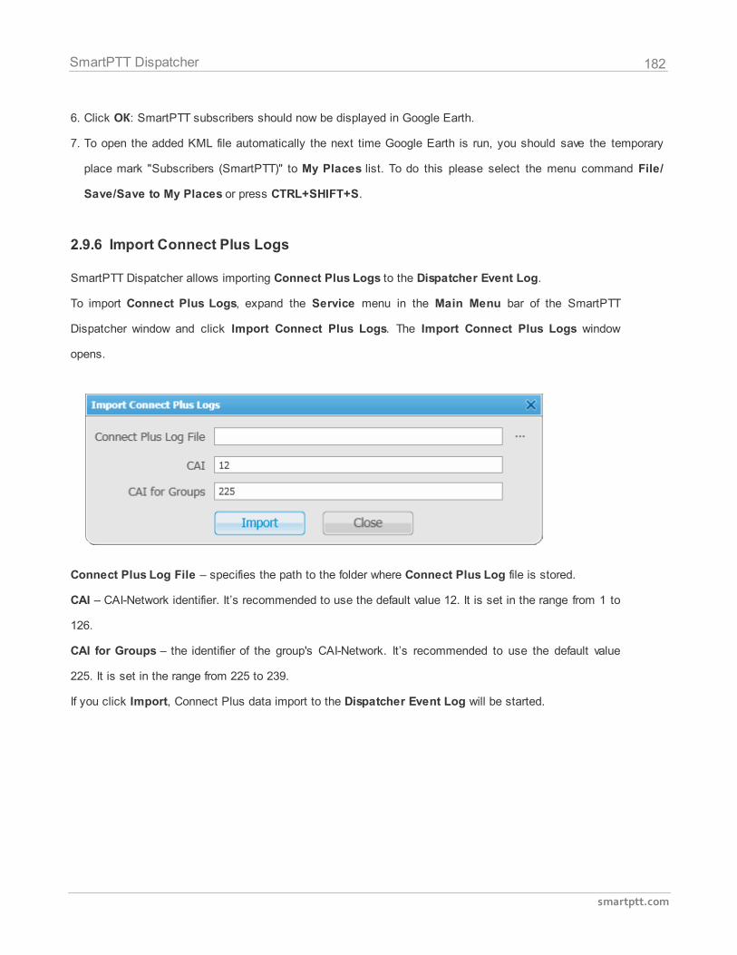
182
smartptt.com
SmartPTT Dispatcher
6. Click ОК: SmartPTT subscribers should now be displayed in Google Earth.
7. To open the added KML file automatically the next time Google Earth is run, you should save the temporary
place mark "Subscribers (SmartPTT)" to My Places list. To do this please select the menu command File/
Save/Save to My Places or press CTRL+SHIFT+S.
2.9.6 Import Connect Plus Logs
SmartPTT Dispatcher allows importing Connect Plus Logs to the Dispatcher Event Log.
To import Connect Plus Logs, expand the Service menu in the Main Menu bar of the SmartPTT
Dispatcher window and click Import Connect Plus Logs. The Import Connect Plus Logs window
opens.
Connect Plus Log File – specifies the path to the folder where Connect Plus Log file is stored.
CAI – CAI-Network identifier. It’s recommended to use the default value 12. It is set in the range from 1 to
126.
CAI for Groups – the identifier of the group's CAI-Network. It’s recommended to use the default value
225. It is set in the range from 225 to 239.
If you click Import, Connect Plus data import to the Dispatcher Event Log will be started.
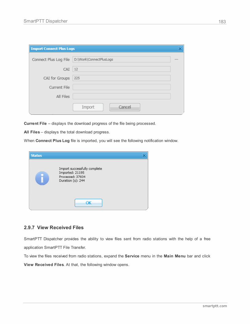
183
smartptt.com
SmartPTT Dispatcher
Current File – displays the download progress of the file being processed.
All Files – displays the total download progress.
When Connect Plus Log file is imported, you will see the following notification window.
2.9.7 View Received Files
SmartPTT Dispatcher provides the ability to view files sent from radio stations with the help of a free
application SmartPTT File Transfer.
To view the files received from radio stations, expand the Service menu in the Main Menu bar and click
View Received Files. At that, the following window opens.
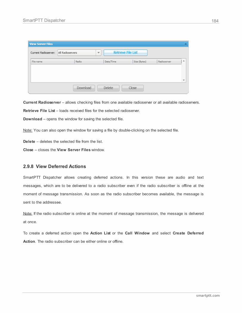
184
smartptt.com
SmartPTT Dispatcher
Current Radioserver – allows checking files from one available radioserver or all available radioservers.
Retrieve File List – loads received files for the selected radioserver.
Download – opens the window for saving the selected file.
Note: You can also open the window for saving a file by double-clicking on the selected file.
Delete – deletes the selected file from the list.
Close – closes the View Server Files window.
2.9.8 View Deferred Actions
SmartPTT Dispatcher allows creating deferred actions. In this version these are audio and text
messages, which are to be delivered to a radio subscriber even if the radio subscriber is offline at the
moment of message transmission. As soon as the radio subscriber becomes available, the message is
sent to the addressee.
Note: If the radio subscriber is online at the moment of message transmission, the message is delivered
at once.
To create a deferred action open the Action List or the Call Window and select Create Deferred
Action. The radio subscriber can be either online or offline.
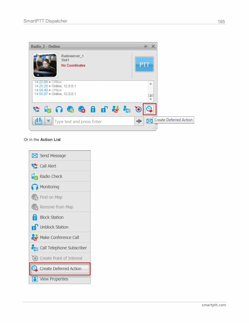
185
smartptt.com
SmartPTT Dispatcher
Or in the Action List
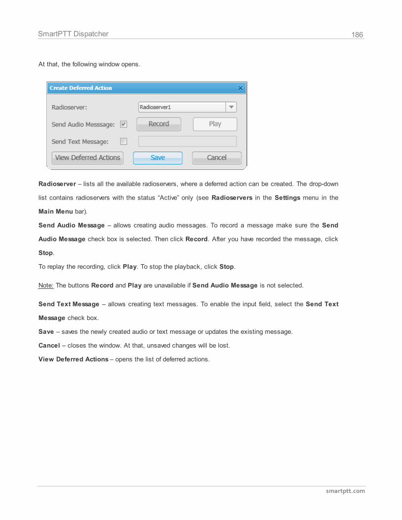
186
smartptt.com
SmartPTT Dispatcher
At that, the following window opens.
Radioserver – lists all the available radioservers, where a deferred action can be created. The drop-down
list contains radioservers with the status “Active” only (see Radioservers in the Settings menu in the
Main Menu bar).
Send Audio Message – allows creating audio messages. To record a message make sure the Send
Audio Message check box is selected. Then click Record. After you have recorded the message, click
Stop.
To replay the recording, click Play. To stop the playback, click Stop.
Note: The buttons Record and Play are unavailable if Send Audio Message is not selected.
Send Text Message – allows creating text messages. To enable the input field, select the Send Text
Message check box.
Save – saves the newly created audio or text message or updates the existing message.
Cancel – closes the window. At that, unsaved changes will be lost.
View Deferred Actions – opens the list of deferred actions.
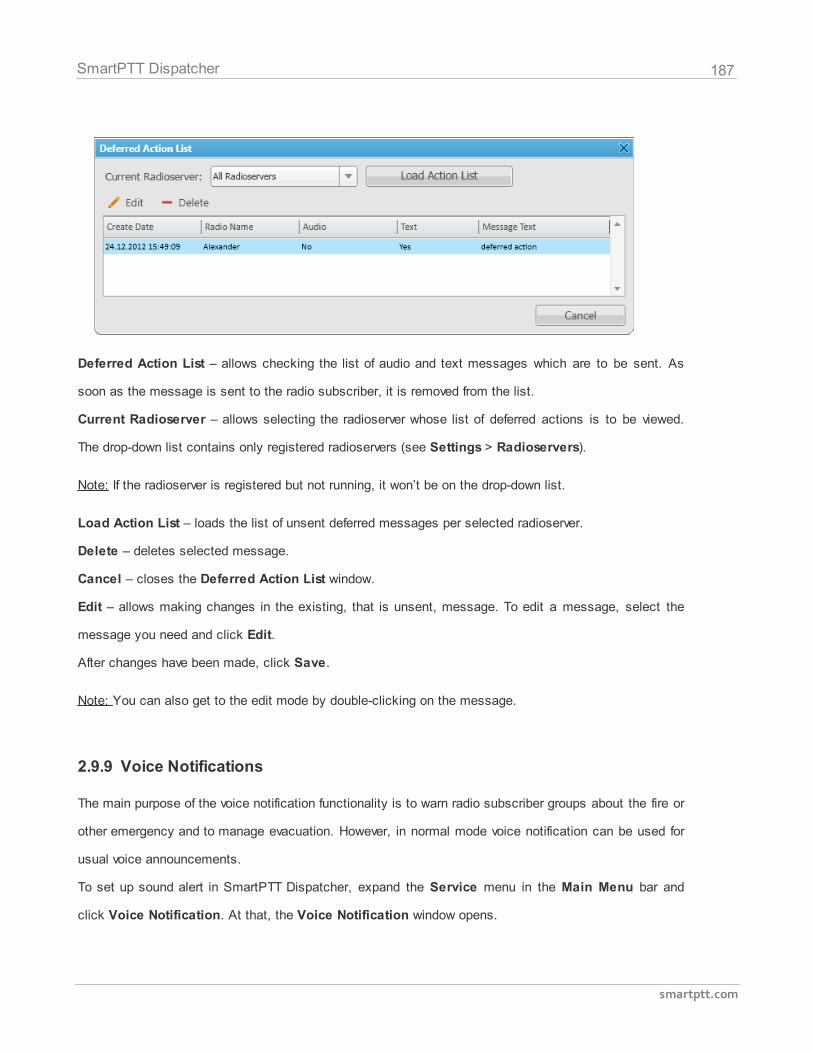
187
smartptt.com
SmartPTT Dispatcher
Deferred Action List – allows checking the list of audio and text messages which are to be sent. As
soon as the message is sent to the radio subscriber, it is removed from the list.
Current Radioserver – allows selecting the radioserver whose list of deferred actions is to be viewed.
The drop-down list contains only registered radioservers (see Settings > Radioservers).
Note: If the radioserver is registered but not running, it won’t be on the drop-down list.
Load Action List – loads the list of unsent deferred messages per selected radioserver.
Delete – deletes selected message.
Cancel – closes the Deferred Action List window.
Edit – allows making changes in the existing, that is unsent, message. To edit a message, select the
message you need and click Edit.
After changes have been made, click Save.
Note: You can also get to the edit mode by double-clicking on the message.
2.9.9 Voice Notifications
The main purpose of the voice notification functionality is to warn radio subscriber groups about the fire or
other emergency and to manage evacuation. However, in normal mode voice notification can be used for
usual voice announcements.
To set up sound alert in SmartPTT Dispatcher, expand the Service menu in the Main Menu bar and
click Voice Notification. At that, the Voice Notification window opens.
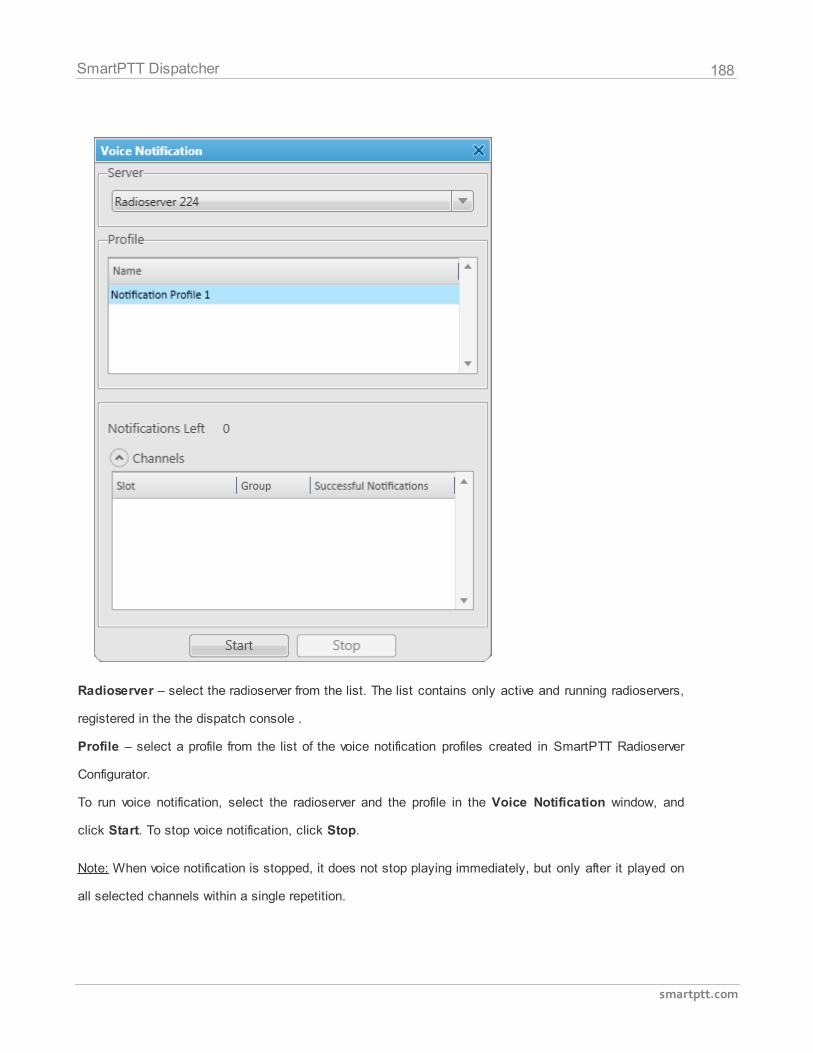
188
smartptt.com
SmartPTT Dispatcher
Radioserver – select the radioserver from the list. The list contains only active and running radioservers,
registered in the the dispatch console .
Profile – select a profile from the list of the voice notification profiles created in SmartPTT Radioserver
Configurator.
To run voice notification, select the radioserver and the profile in the Voice Notification window, and
click Start. To stop voice notification, click Stop.
Note: When voice notification is stopped, it does not stop playing immediately, but only after it played on
all selected channels within a single repetition.
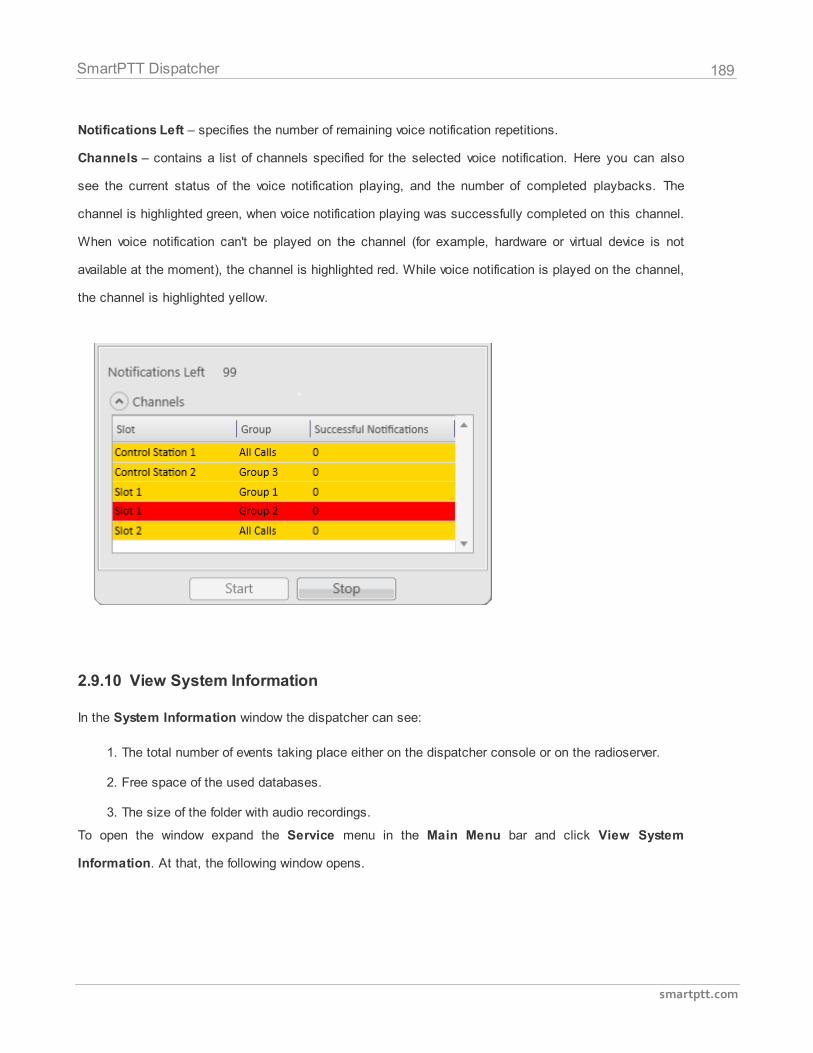
189
smartptt.com
SmartPTT Dispatcher
Notifications Left – specifies the number of remaining voice notification repetitions.
Channels – contains a list of channels specified for the selected voice notification. Here you can also
see the current status of the voice notification playing, and the number of completed playbacks. The
channel is highlighted green, when voice notification playing was successfully completed on this channel.
When voice notification can't be played on the channel (for example, hardware or virtual device is not
available at the moment), the channel is highlighted red. While voice notification is played on the channel,
the channel is highlighted yellow.
2.9.10 View System Information
In the System Information window the dispatcher can see:
1. The total number of events taking place either on the dispatcher console or on the radioserver.
2. Free space of the used databases.
3. The size of the folder with audio recordings.
To open the window expand the Service menu in the Main Menu bar and click View System
Information. At that, the following window opens.
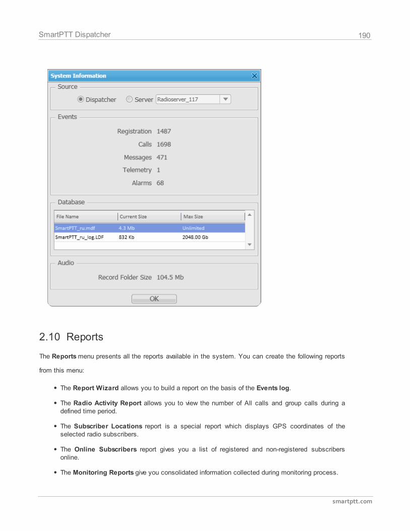
190
smartptt.com
SmartPTT Dispatcher
2.10 Reports
The Reports menu presents all the reports available in the system. You can create the following reports
from this menu:
The Report Wizard allows you to build a report on the basis of the Events log.
The Radio Activity Report allows you to view the number of All calls and group calls during adefined time period.
The Subscriber Locations report is a special report which displays GPS coordinates of theselected radio subscribers.
The Online Subscribers report gives you a list of registered and non-registered subscribersonline.
The Monitoring Reports give you consolidated information collected during monitoring process.
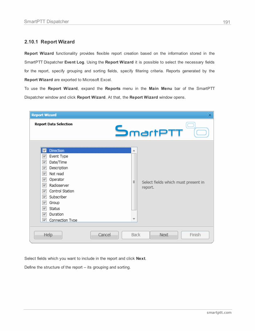
191
smartptt.com
SmartPTT Dispatcher
2.10.1 Report Wizard
Report Wizard functionality provides flexible report creation based on the information stored in the
SmartPTT Dispatcher Event Log. Using the Report Wizard it is possible to select the necessary fields
for the report, specify grouping and sorting fields, specify filtering criteria. Reports generated by the
Report Wizard are exported to Microsoft Excel.
To use the Report Wizard, expand the Reports menu in the Main Menu bar of the SmartPTT
Dispatcher window and click Report Wizard. At that, the Report Wizard window opens.
Select fields which you want to include in the report and click Next.
Define the structure of the report – its grouping and sorting.
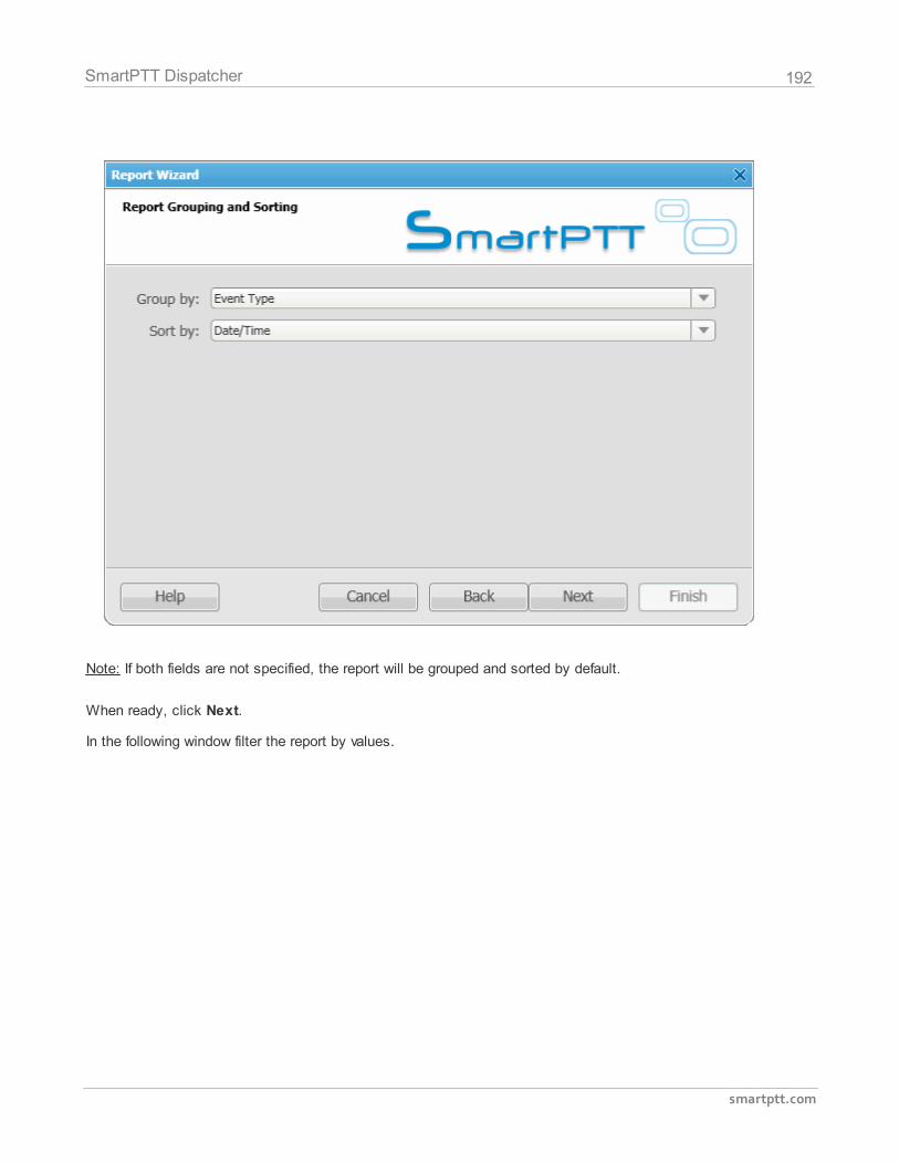
192
smartptt.com
SmartPTT Dispatcher
Note: If both fields are not specified, the report will be grouped and sorted by default.
When ready, click Next.
In the following window filter the report by values.
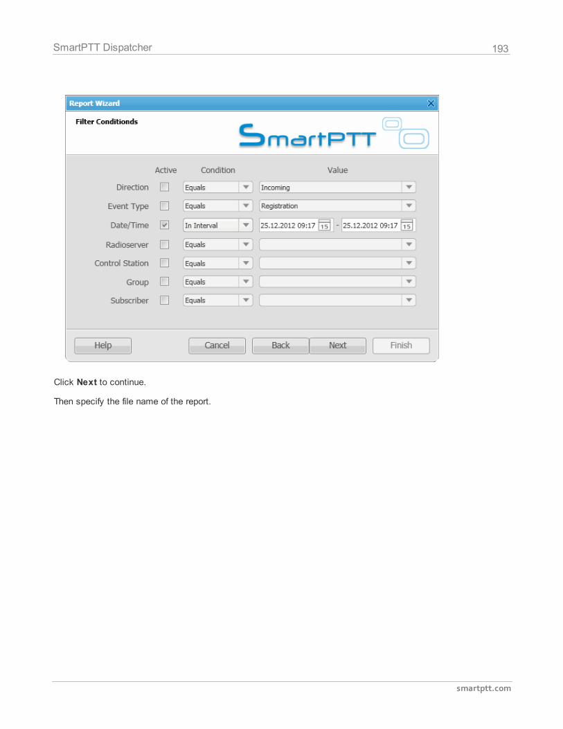
193
smartptt.com
SmartPTT Dispatcher
Click Next to continue.
Then specify the file name of the report.
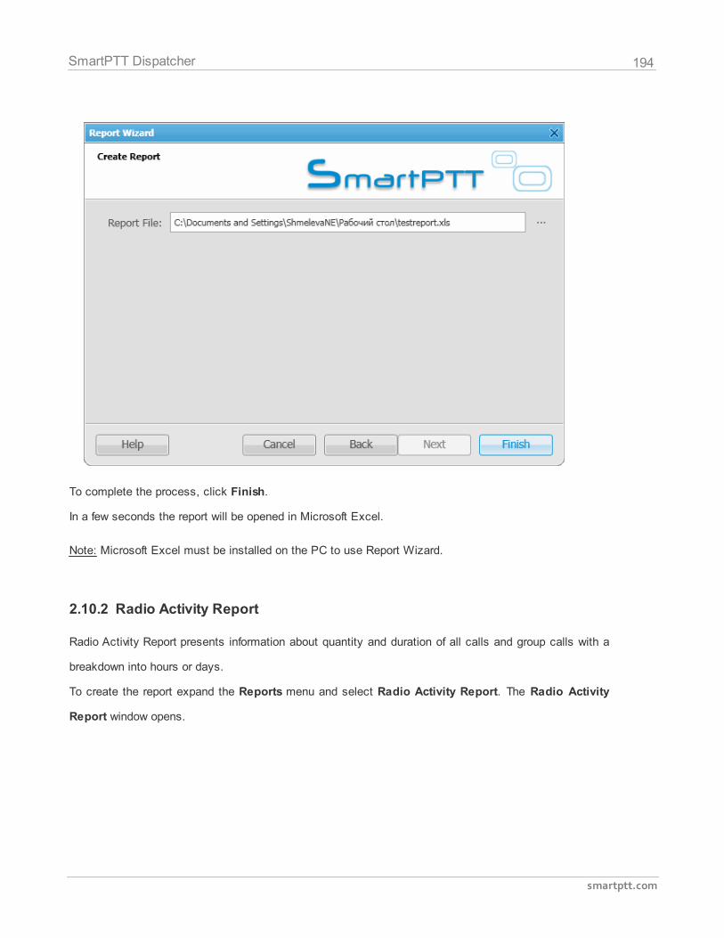
194
smartptt.com
SmartPTT Dispatcher
To complete the process, click Finish.
In a few seconds the report will be opened in Microsoft Excel.
Note: Microsoft Excel must be installed on the PC to use Report Wizard.
2.10.2 Radio Activity Report
Radio Activity Report presents information about quantity and duration of all calls and group calls with a
breakdown into hours or days.
To create the report expand the Reports menu and select Radio Activity Report. The Radio Activity
Report window opens.
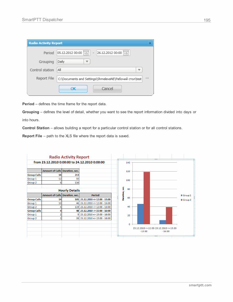
195
smartptt.com
SmartPTT Dispatcher
Period – defines the time frame for the report data.
Grouping – defines the level of detail, whether you want to see the report information divided into days or
into hours.
Control Station – allows building a report for a particular control station or for all control stations.
Report File – path to the XLS file where the report data is saved.
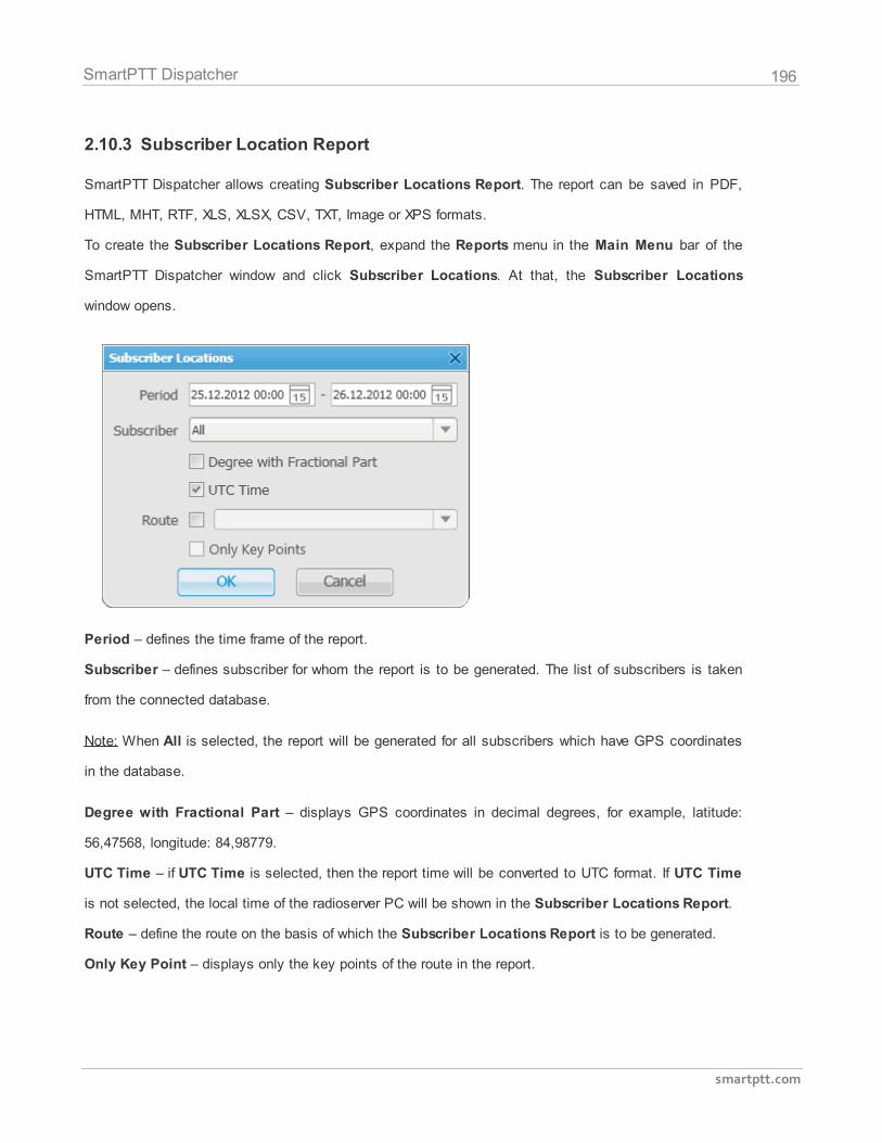
196
smartptt.com
SmartPTT Dispatcher
2.10.3 Subscriber Location Report
SmartPTT Dispatcher allows creating Subscriber Locations Report. The report can be saved in PDF,
HTML, MHT, RTF, XLS, XLSX, CSV, TXT, Image or XPS formats.
To create the Subscriber Locations Report, expand the Reports menu in the Main Menu bar of the
SmartPTT Dispatcher window and click Subscriber Locations. At that, the Subscriber Locations
window opens.
Period – defines the time frame of the report.
Subscriber – defines subscriber for whom the report is to be generated. The list of subscribers is taken
from the connected database.
Note: When All is selected, the report will be generated for all subscribers which have GPS coordinates
in the database.
Degree with Fractional Part – displays GPS coordinates in decimal degrees, for example, latitude:
56,47568, longitude: 84,98779.
UTC Time – if UTC Time is selected, then the report time will be converted to UTC format. If UTC Time
is not selected, the local time of the radioserver PC will be shown in the Subscriber Locations Report.
Route – define the route on the basis of which the Subscriber Locations Report is to be generated.
Only Key Point – displays only the key points of the route in the report.
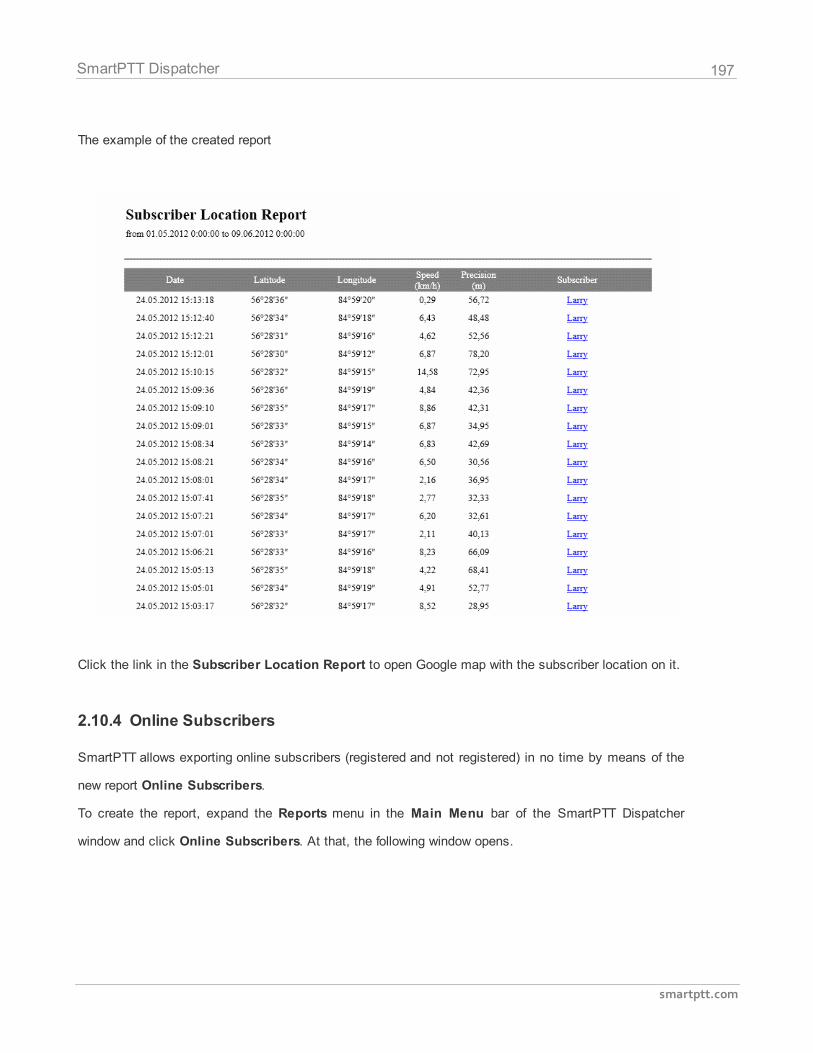
197
smartptt.com
SmartPTT Dispatcher
The example of the created report
Click the link in the Subscriber Location Report to open Google map with the subscriber location on it.
2.10.4 Online Subscribers
SmartPTT allows exporting online subscribers (registered and not registered) in no time by means of the
new report Online Subscribers.
To create the report, expand the Reports menu in the Main Menu bar of the SmartPTT Dispatcher
window and click Online Subscribers. At that, the following window opens.
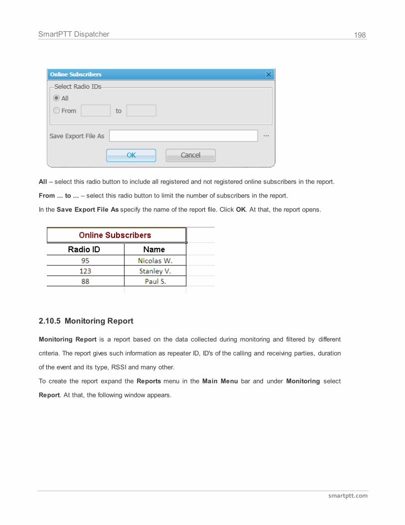
198
smartptt.com
SmartPTT Dispatcher
All – select this radio button to include all registered and not registered online subscribers in the report.
From ... to ... – select this radio button to limit the number of subscribers in the report.
In the Save Export File As specify the name of the report file. Click OK. At that, the report opens.
2.10.5 Monitoring Report
Monitoring Report is a report based on the data collected during monitoring and filtered by different
criteria. The report gives such information as repeater ID, ID's of the calling and receiving parties, duration
of the event and its type, RSSI and many other.
To create the report expand the Reports menu in the Main Menu bar and under Monitoring select
Report. At that, the following window appears.
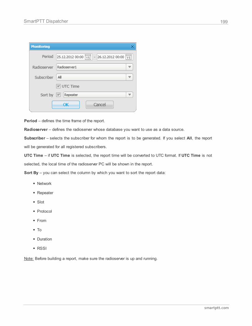
199
smartptt.com
SmartPTT Dispatcher
Period – defines the time frame of the report.
Radioserver – defines the radioserver whose database you want to use as a data source.
Subscriber – selects the subscriber for whom the report is to be generated. If you select All, the report
will be generated for all registered subscribers.
UTC Time – if UTC Time is selected, the report time will be converted to UTC format. If UTC Time is not
selected, the local time of the radioserver PC will be shown in the report.
Sort By – you can select the column by which you want to sort the report data:
Network
Repeater
Slot
Protocol
From
To
Duration
RSSI
Note: Before building a report, make sure the radioserver is up and running.
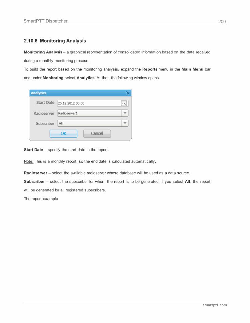
200
smartptt.com
SmartPTT Dispatcher
2.10.6 Monitoring Analysis
Monitoring Analysis – a graphical representation of consolidated information based on the data received
during a monthly monitoring process.
To build the report based on the monitoring analysis, expand the Reports menu in the Main Menu bar
and under Monitoring select Analytics. At that, the following window opens.
Start Date – specify the start date in the report.
Note: This is a monthly report, so the end date is calculated automatically.
Radioserver – select the available radioserver whose database will be used as a data source.
Subscriber – select the subscriber for whom the report is to be generated. If you select All, the report
will be generated for all registered subscribers.
The report example
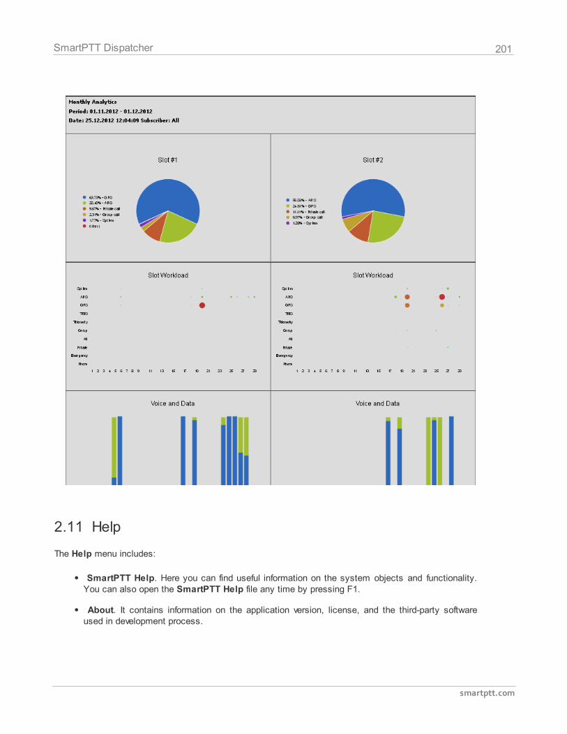
201
smartptt.com
SmartPTT Dispatcher
2.11 Help
The Help menu includes:
SmartPTT Help. Here you can find useful information on the system objects and functionality.You can also open the SmartPTT Help file any time by pressing F1.
About. It contains information on the application version, license, and the third-party softwareused in development process.
202
smartptt.com
SmartPTT Dispatcher
2.12 Bridging
SmartPTT Bridging service allows joining multiple network systems into a single radio network. The
bridging service is implemented by SmartPTT Radioserver and provides intelligent means of patching for
voice and data streams between various network systems.
Radio network configurations supporting bridging:
1. MOTOTRBO IP Site Connect networks
2. Capacity Plus sites
3. Digital conventional channels
4. Analog conventional channels
SmartPTT bridging service allows you to:
Join various radio networks.
Bridge two or more radioservers to cover distributed regions.
Bridge selected voice and data.
Bridge private and group calls dynamically.
Break the barrier of 15 repeaters per IP Site Connect,
Have calls bridged with only a short voice delay (from 60 ms), when joining IP Site Connectsystems.
How to Configure Bridging in SmartPTT Dispatcher Console
You can configure bridging settings in the call bridging table in SmartPTT Dispatcher. It was designed to
make the process of bridging configuration simple and easy. The main idea of the configuration process
is to manage bridging with the help of the so-called "Profiles" and "Route Groups". The profiles contain
information on the bridging rules, which are specified in route groups and further in routes. So, there are
three levels:
1. Routes
2. Route Groups
3. Profiles
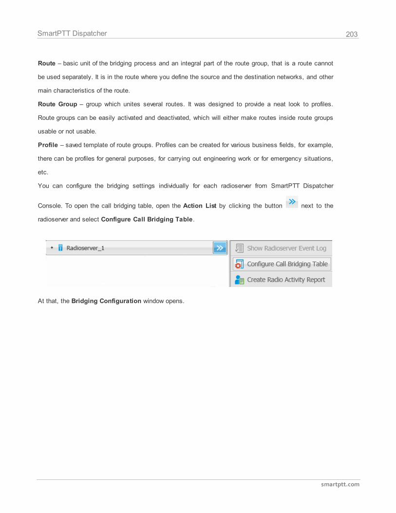
203
smartptt.com
SmartPTT Dispatcher
Route – basic unit of the bridging process and an integral part of the route group, that is a route cannot
be used separately. It is in the route where you define the source and the destination networks, and other
main characteristics of the route.
Route Group – group which unites several routes. It was designed to provide a neat look to profiles.
Route groups can be easily activated and deactivated, which will either make routes inside route groups
usable or not usable.
Profile – saved template of route groups. Profiles can be created for various business fields, for example,
there can be profiles for general purposes, for carrying out engineering work or for emergency situations,
etc.
You can configure the bridging settings individually for each radioserver from SmartPTT Dispatcher
Console. To open the call bridging table, open the Action List by clicking the button next to the
radioserver and select Configure Call Bridging Table.
At that, the Bridging Configuration window opens.
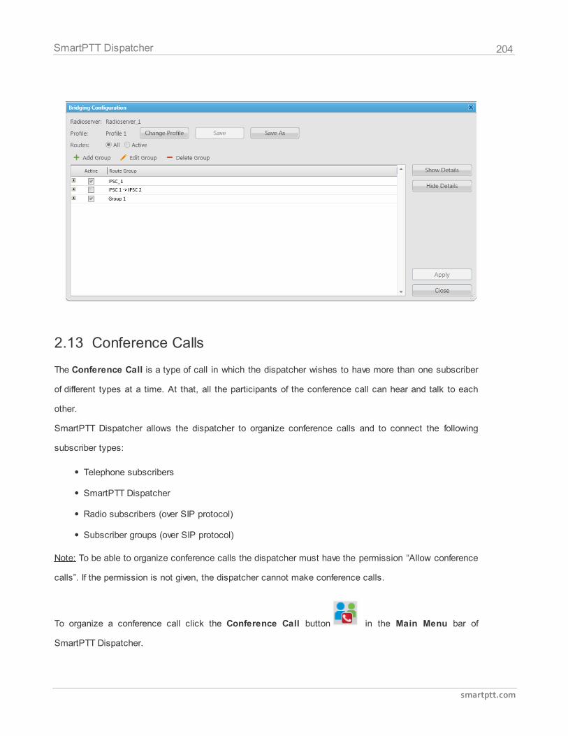
204
smartptt.com
SmartPTT Dispatcher
2.13 Conference Calls
The Conference Call is a type of call in which the dispatcher wishes to have more than one subscriber
of different types at a time. At that, all the participants of the conference call can hear and talk to each
other.
SmartPTT Dispatcher allows the dispatcher to organize conference calls and to connect the following
subscriber types:
Telephone subscribers
SmartPTT Dispatcher
Radio subscribers (over SIP protocol)
Subscriber groups (over SIP protocol)
Note: To be able to organize conference calls the dispatcher must have the permission “Allow conference
calls”. If the permission is not given, the dispatcher cannot make conference calls.
To organize a conference call click the Conference Call button in the Main Menu bar of
SmartPTT Dispatcher.
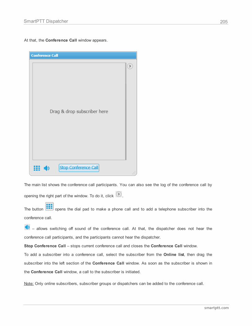
205
smartptt.com
SmartPTT Dispatcher
At that, the Conference Call window appears.
The main list shows the conference call participants. You can also see the log of the conference call by
opening the right part of the window. To do it, click .
The button opens the dial pad to make a phone call and to add a telephone subscriber into the
conference call.
– allows switching off sound of the conference call. At that, the dispatcher does not hear the
conference call participants, and the participants cannot hear the dispatcher.
Stop Conference Call – stops current conference call and closes the Conference Call window.
To add a subscriber into a conference call, select the subscriber from the Online list, then drag the
subscriber into the left section of the Conference Call window. As soon as the subscriber is shown in
the Conference Call window, a call to the subscriber is initiated.
Note: Only online subscribers, subscriber groups or dispatchers can be added to the conference call.
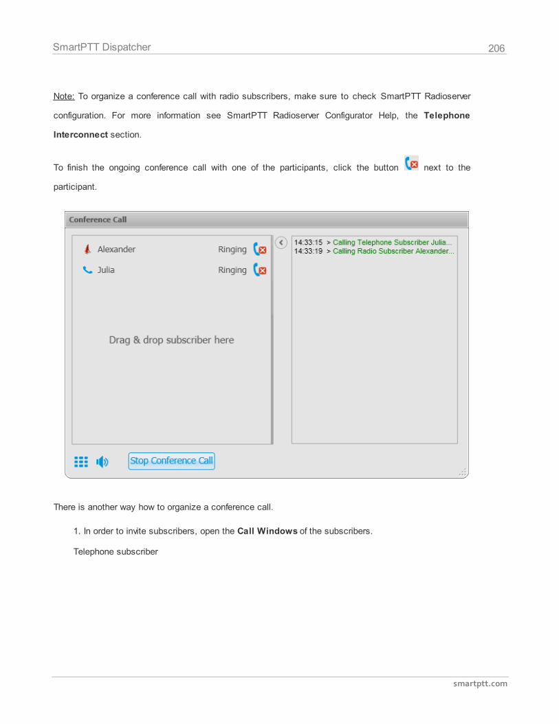
206
smartptt.com
SmartPTT Dispatcher
Note: To organize a conference call with radio subscribers, make sure to check SmartPTT Radioserver
configuration. For more information see SmartPTT Radioserver Configurator Help, the Telephone
Interconnect section.
To finish the ongoing conference call with one of the participants, click the button next to the
participant.
There is another way how to organize a conference call.
1. In order to invite subscribers, open the Call Windows of the subscribers.
Telephone subscriber
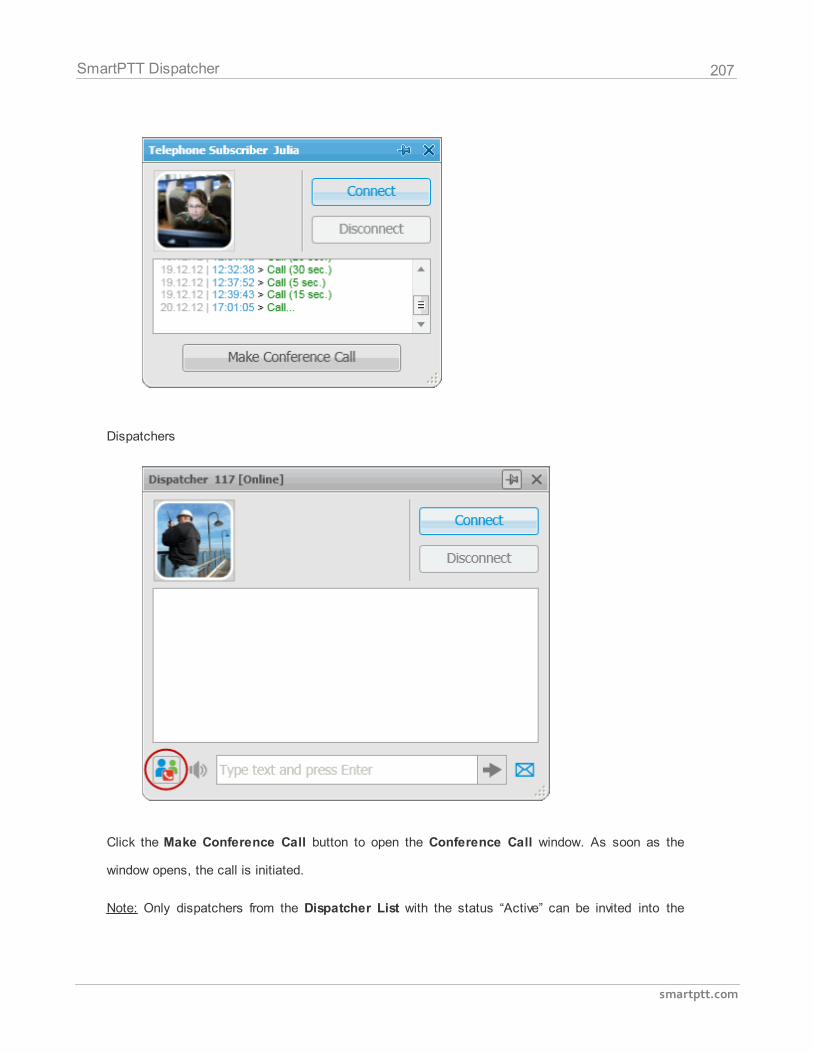
207
smartptt.com
SmartPTT Dispatcher
Dispatchers
Click the Make Conference Call button to open the Conference Call window. As soon as the
window opens, the call is initiated.
Note: Only dispatchers from the Dispatcher List with the status “Active” can be invited into the
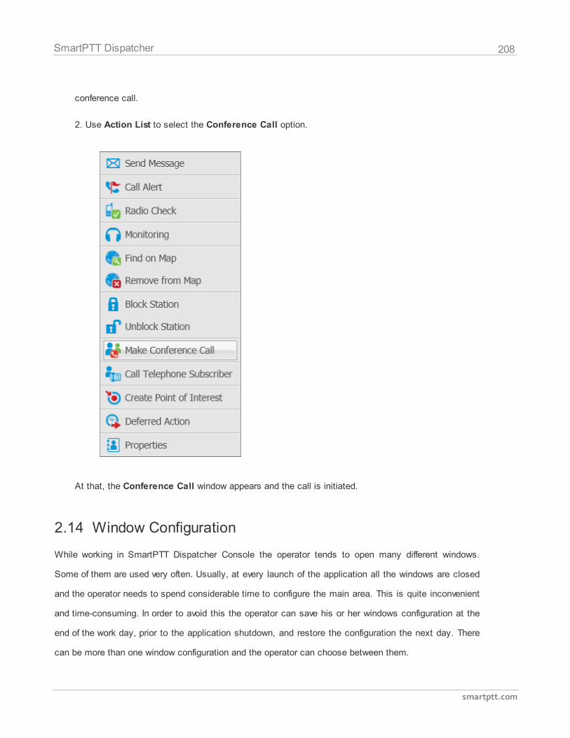
208
smartptt.com
SmartPTT Dispatcher
conference call.
2. Use Action List to select the Conference Call option.
At that, the Conference Call window appears and the call is initiated.
2.14 Window Configuration
While working in SmartPTT Dispatcher Console the operator tends to open many different windows.
Some of them are used very often. Usually, at every launch of the application all the windows are closed
and the operator needs to spend considerable time to configure the main area. This is quite inconvenient
and time-consuming. In order to avoid this the operator can save his or her windows configuration at the
end of the work day, prior to the application shutdown, and restore the configuration the next day. There
can be more than one window configuration and the operator can choose between them.
209
smartptt.com
SmartPTT Dispatcher
To save the current window configuration for future use, click the Window Configurations button
in the Main Menu bar.
Click Add to give the name to the current window configuration. At that, the opened windows will be
grasped and saved.
Click Apply to restore the saved windows configuration.
Click Delete to remove the saved windows configuration.
2.15 Panel Positioning
There is an ability to adjust the layout of the opened panels in the Main area.
To do it, you need to click on the tab of the opened panel and while holding it, drag it to the position
where you want it to place it on the screen. As soon as you start dragging it, you will see new icons
appear on the screen. The icons represent positioning of the panel on the screen. To place the panel in a
new position you need to drop the tab when the cursor is over one of these icons.
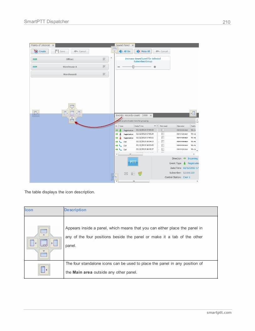
210
smartptt.com
SmartPTT Dispatcher
The table displays the icon description.
Icon Description
Appears inside a panel, which means that you can either place the panel in
any of the four positions beside the panel or make it a tab of the other
panel.
The four standalone icons can be used to place the panel in any position of
the Main area outside any other panel.
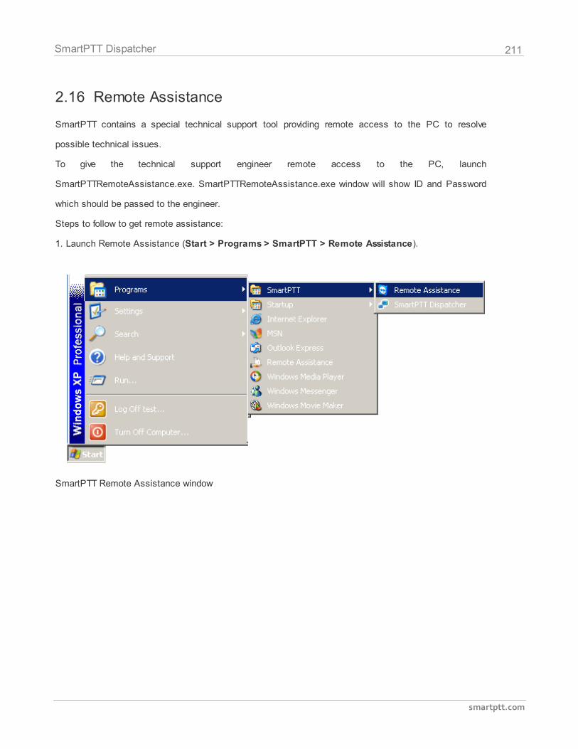
211
smartptt.com
SmartPTT Dispatcher
2.16 Remote Assistance
SmartPTT contains a special technical support tool providing remote access to the PC to resolve
possible technical issues.
To give the technical support engineer remote access to the PC, launch
SmartPTTRemoteAssistance.exe. SmartPTTRemoteAssistance.exe window will show ID and Password
which should be passed to the engineer.
Steps to follow to get remote assistance:
1. Launch Remote Assistance (Start > Programs > SmartPTT > Remote Assistance).
SmartPTT Remote Assistance window
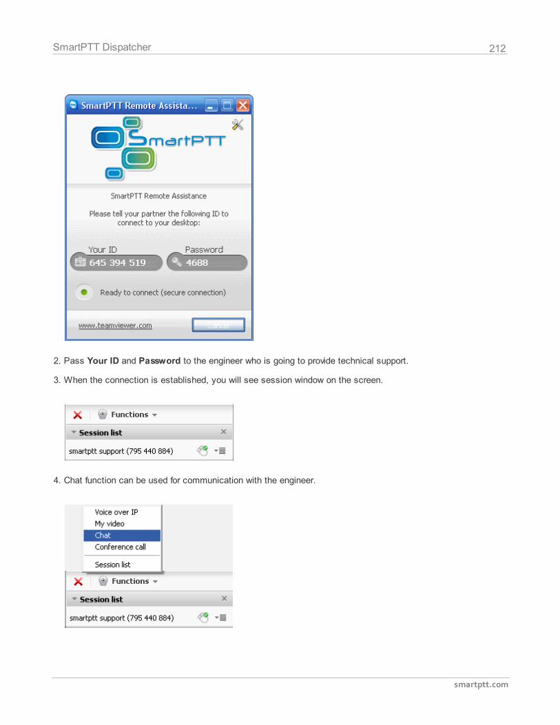
212
smartptt.com
SmartPTT Dispatcher
2. Pass Your ID and Password to the engineer who is going to provide technical support.
3. When the connection is established, you will see session window on the screen.
4. Chat function can be used for communication with the engineer.

213
smartptt.com
SmartPTT Dispatcher
5. To stop the session click .
214
smartptt.com
SmartPTT Dispatcher
3 SmartPTT Radioserver Configurator
3.1 Main Features
SmartPTT Radioserver Configurator is an application designed as a tool to configure SmartPTT
Radioserver parameters.
SmartPTT Radioserver is an application server implemented as a Windows service.
The radioserver setup process includes configuration of registration, location, text messaging, control
station services and other settings. The document presents a full list of system features.
The registration service provides information on availability of subscriber radios in the radio network.
The location service provides coordinates of subscriber radios with a GPS receiver so you can
determine their current location.
The text messaging service is used to exchange text messages between dispatchers and radio
subscribers.
The telemetry service is used for transmission and processing of telemetry signals between the
dispatcher console and radio subscribers.
The telephone interconnect service allows establishing intercommunication between telephone and
radio subscribers.
The event log provides functionality for saving and representation of all events specific for the SmartPTT
system and also incoming or outgoing voice records.
Control Station (Analog) is an analog control station connected to the computer COM port via an
interface card.
Control station settings also include the setting up of channels, groups and audio parameters.
Control Station MOTOTRBO is a mobile radio station connected via USB port to the computer and used
as a radio network gateway. You can connect up to four control stations to the MOTOTRBO system.
SmartPTT Enterprise implements a direct connection of the radioserver to the repeater’s network
functioning in IP Site Connect system. SmartPTT Enterprise allows a simultaneous control of multiple IP

215
smartptt.com
SmartPTT Radioserver Configurator
Site Connect systems.
SmartPTT Radioserver Configurator allows creating permission profiles used to limit operators' access
to the objects managed by the radioserver, such as control stations, groups, services, IP Site Connect
slots, etc.
3.2 Radioserver
To set up the radioserver, click Radioserver in the left list of the SmartPTT Radioserver Configurator
window. At that, the settings window will display on the right.
Name – radioserver alias. You cannot type more than 20 characters into this field.
Address (Interface:Port) – radioserver address. Default port is 8888.
Authentication – authentication parameters required for connection to the radioserver.
No – anonymous authentication.
Windows – Windows authentication. To connect, the dispatcher must use the user name and password
of the account where the radioserver service was started.
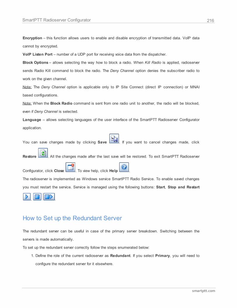
216
smartptt.com
SmartPTT Radioserver Configurator
Encryption – this function allows users to enable and disable encryption of transmitted data. VoIP data
cannot by encrypted.
VoIP Listen Port – number of a UDP port for receiving voice data from the dispatcher.
Block Options – allows selecting the way how to block a radio. When Kill Radio is applied, radioserver
sends Radio Kill command to block the radio. The Deny Channel option denies the subscriber radio to
work on the given channel.
Note: The Deny Channel option is applicable only to IP Site Connect (direct IP connection) or MNAI
based configurations.
Note: When the Block Radio command is sent from one radio unit to another, the radio will be blocked,
even if Deny Channel is selected.
Language – allows selecting languages of the user interface of the SmartPTT Radioserver Configurator
application.
You can save changes made by clicking Save . If you want to cancel changes made, click
Restore . All the changes made after the last save will be restored. To exit SmartPTT Radioserver
Configurator, click Close . To view help, click Help .
The radioserver is implemented as Windows service SmartPTT Radio Service. To enable saved changes
you must restart the service. Service is managed using the following buttons: Start, Stop and Restart
, .
How to Set up the Redundant Server
The redundant server can be useful in case of the primary server breakdown. Switching between the
servers is made automatically.
To set up the redundant server correctly follow the steps enumerated below:
1. Define the role of the current radioserver as Redundant. If you select Primary, you will need to
configure the redundant server for it elsewhere.
217
smartptt.com
SmartPTT Radioserver Configurator
Note: A primary server can be backed up with only one redundant server.
2. Fill in the fields Primary Server Address (host:port) and Connection Timeout.
Primary Server Address (host:port) – IP address and port of the computer where the primary
radioserver is installed.
Connection Timeout, sec – time interval which starts ticking as soon as the primary server is
down. If the primary server has not recovered within the specified time interval, the redundant server
takes over.
Note: The Primary Server Address (host:port) and Connection Timeout fields are unavailable if
the role of the server is set to Primary.
How to Limit the Number of Radios
The Limit Radios to Service area was designed to manage the number of radios allowed in the network.
Here the user can specify which radios are to be controlled by the system and which are not.
To make this functionality active select Enabled. Then, in the Allowed Radio Numbers field, enter ID's
of the radios which are to be controlled by the system.
Warning! All the radios whose ID's were not specified will be ignored by the SmartPTT system.
3.2.1 Services
3.2.1.1 ARS
ARS or registration service provides information on the availability of radio subscribers in the radio
network.
To set up ARS parameters, click ARS in the list in the left area of the SmartPTT Radioserver
Configurator window. At that, a new window appears on the right.
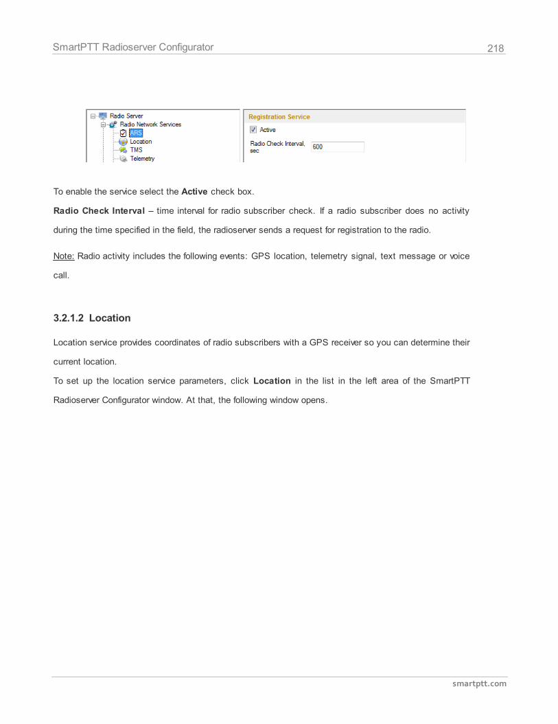
218
smartptt.com
SmartPTT Radioserver Configurator
To enable the service select the Active check box.
Radio Check Interval – time interval for radio subscriber check. If a radio subscriber does no activity
during the time specified in the field, the radioserver sends a request for registration to the radio.
Note: Radio activity includes the following events: GPS location, telemetry signal, text message or voice
call.
3.2.1.2 Location
Location service provides coordinates of radio subscribers with a GPS receiver so you can determine their
current location.
To set up the location service parameters, click Location in the list in the left area of the SmartPTT
Radioserver Configurator window. At that, the following window opens.
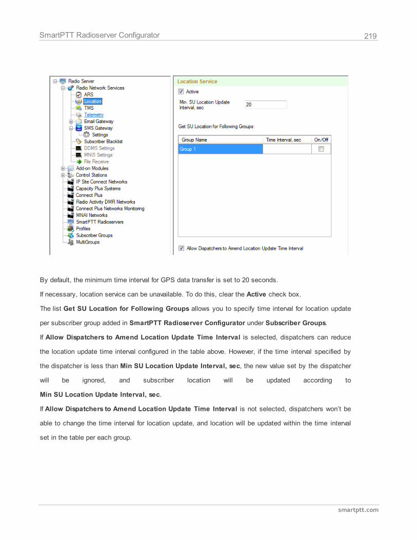
219
smartptt.com
SmartPTT Radioserver Configurator
By default, the minimum time interval for GPS data transfer is set to 20 seconds.
If necessary, location service can be unavailable. To do this, clear the Active check box.
The list Get SU Location for Following Groups allows you to specify time interval for location update
per subscriber group added in SmartPTT Radioserver Configurator under Subscriber Groups.
If Allow Dispatchers to Amend Location Update Time Interval is selected, dispatchers can reduce
the location update time interval configured in the table above. However, if the time interval specified by
the dispatcher is less than Min SU Location Update Interval, sec, the new value set by the dispatcher
will be ignored, and subscriber location will be updated according to
Min SU Location Update Interval, sec.
If Allow Dispatchers to Amend Location Update Time Interval is not selected, dispatchers won’t be
able to change the time interval for location update, and location will be updated within the time interval
set in the table per each group.
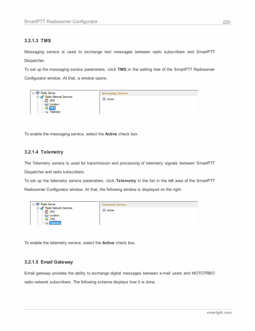
220
smartptt.com
SmartPTT Radioserver Configurator
3.2.1.3 TMS
Messaging service is used to exchange text messages between radio subscribers and SmartPTT
Dispatcher.
To set up the messaging service parameters, click TMS in the setting tree of the SmartPTT Radioserver
Configurator window. At that, a window opens.
To enable the messaging service, select the Active check box.
3.2.1.4 Telemetry
The Telemetry service is used for transmission and processing of telemetry signals between SmartPTT
Dispatcher and radio subscribers.
To set up the telemetry service parameters, click Telemetry in the list in the left area of the SmartPTT
Radioserver Configurator window. At that, the following window is displayed on the right.
To enable the telemetry service, select the Active check box.
3.2.1.5 Email Gateway
Email gateway provides the ability to exchange digital messages between e-mail users and MOTOTRBO
radio network subscribers. The following scheme displays how it is done.
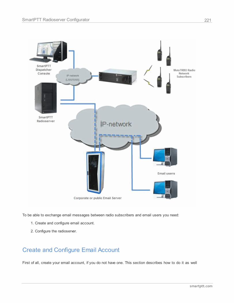
221
smartptt.com
SmartPTT Radioserver Configurator
To be able to exchange email messages between radio subscribers and email users you need:
1. Create and configure email account.
2. Configure the radioserver.
Create and Configure Email Account
First of all, create your email account, if you do not have one. This section describes how to do it as well
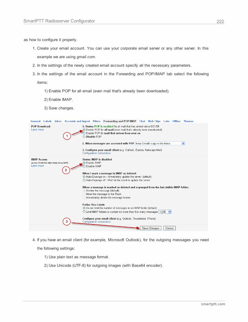
222
smartptt.com
SmartPTT Radioserver Configurator
as how to configure it properly.
1. Create your email account. You can use your corporate email server or any other server. In this
example we are using gmail.com.
2. In the settings of the newly created email account specify all the necessary parameters.
3. In the settings of the email account in the Forwarding and POP/IMAP tab select the following
items:
1) Enable POP for all email (even mail that's already been downloaded).
2) Enable IMAP.
3) Save changes.
4. If you have an email client (for example, Microsoft Outlook), for the outgoing messages you need
the following settings:
1) Use plain text as message format.
2) Use Unicode (UTF-8) for outgoing images (with Base64 encoder).
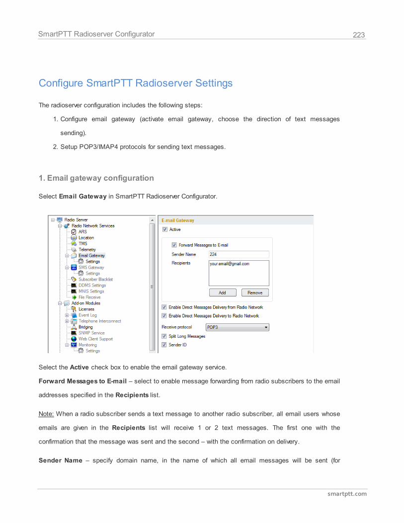
223
smartptt.com
SmartPTT Radioserver Configurator
Configure SmartPTT Radioserver Settings
The radioserver configuration includes the following steps:
1. Configure email gateway (activate email gateway, choose the direction of text messages
sending).
2. Setup POP3/IMAP4 protocols for sending text messages.
1. Email gateway configuration
Select Email Gateway in SmartPTT Radioserver Configurator.
Select the Active check box to enable the email gateway service.
Forward Messages to E-mail – select to enable message forwarding from radio subscribers to the email
addresses specified in the Recipients list.
Note: When a radio subscriber sends a text message to another radio subscriber, all email users whose
emails are given in the Recipients list will receive 1 or 2 text messages. The first one with the
confirmation that the message was sent and the second – with the confirmation on delivery.
Sender Name – specify domain name, in the name of which all email messages will be sent (for
224
smartptt.com
SmartPTT Radioserver Configurator
example, smartptt.com).
Recipients – list of email addresses to receive forwarded text messages.
Enable Direct Message Delivery from Radio Network – forwarding mail messages directly from radio
subscribers.
Enable Direct Message Delivery to Radio Network – forwarding mail messages directly to radio
subscribers.
Receive protocol – select protocol for email message receiving (POP3 or IMAP4).
Split Long Messages – if not selected, a long E-mail message (over 140 characters) addressed to a
radio is trimmed to size limit (that is some information gets lost). If selected, the original message is split
into several packages during transmission. Thus, the radio subscriber receives the message without
information loss.
Sender ID – when selected, the received message contains the sender e-mail address.
2.1. POP3 protocol configuration
In the Receive Protocol field, select POP3 and click Settings in the left setting tree.
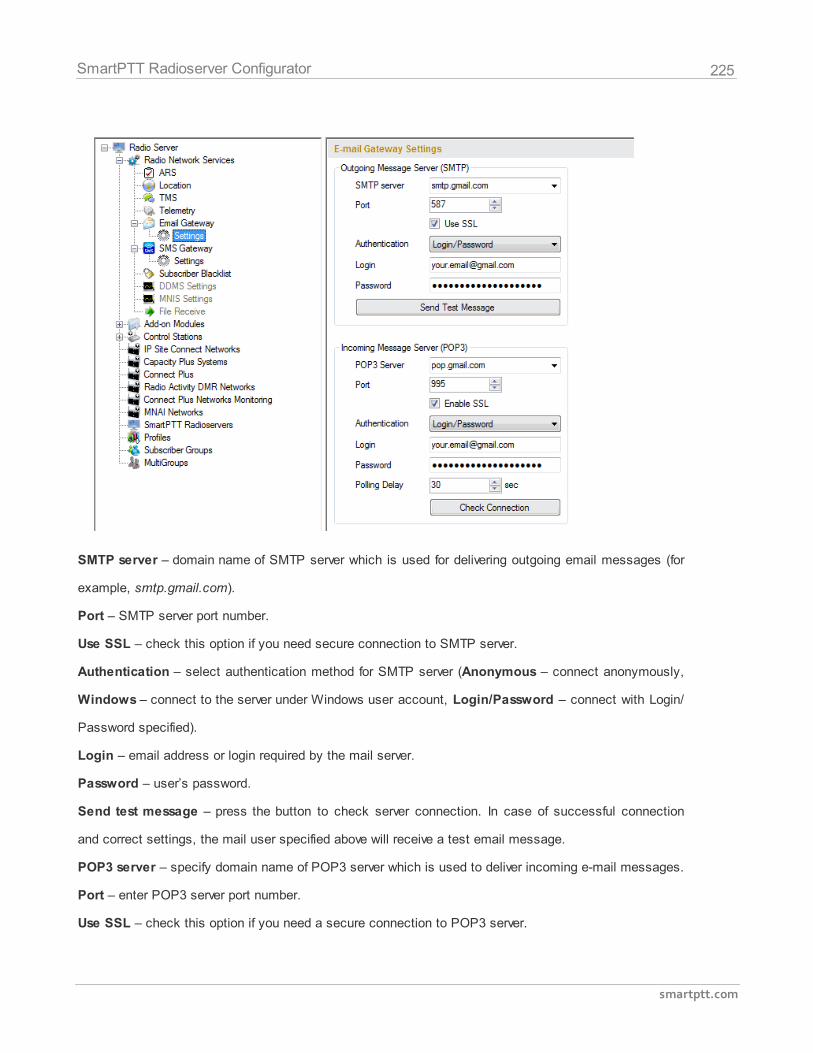
225
smartptt.com
SmartPTT Radioserver Configurator
SMTP server – domain name of SMTP server which is used for delivering outgoing email messages (for
example, smtp.gmail.com).
Port – SMTP server port number.
Use SSL – check this option if you need secure connection to SMTP server.
Authentication – select authentication method for SMTP server (Anonymous – connect anonymously,
Windows – connect to the server under Windows user account, Login/Password – connect with Login/
Password specified).
Login – email address or login required by the mail server.
Password – user’s password.
Send test message – press the button to check server connection. In case of successful connection
and correct settings, the mail user specified above will receive a test email message.
POP3 server – specify domain name of POP3 server which is used to deliver incoming e-mail messages.
Port – enter POP3 server port number.
Use SSL – check this option if you need a secure connection to POP3 server.
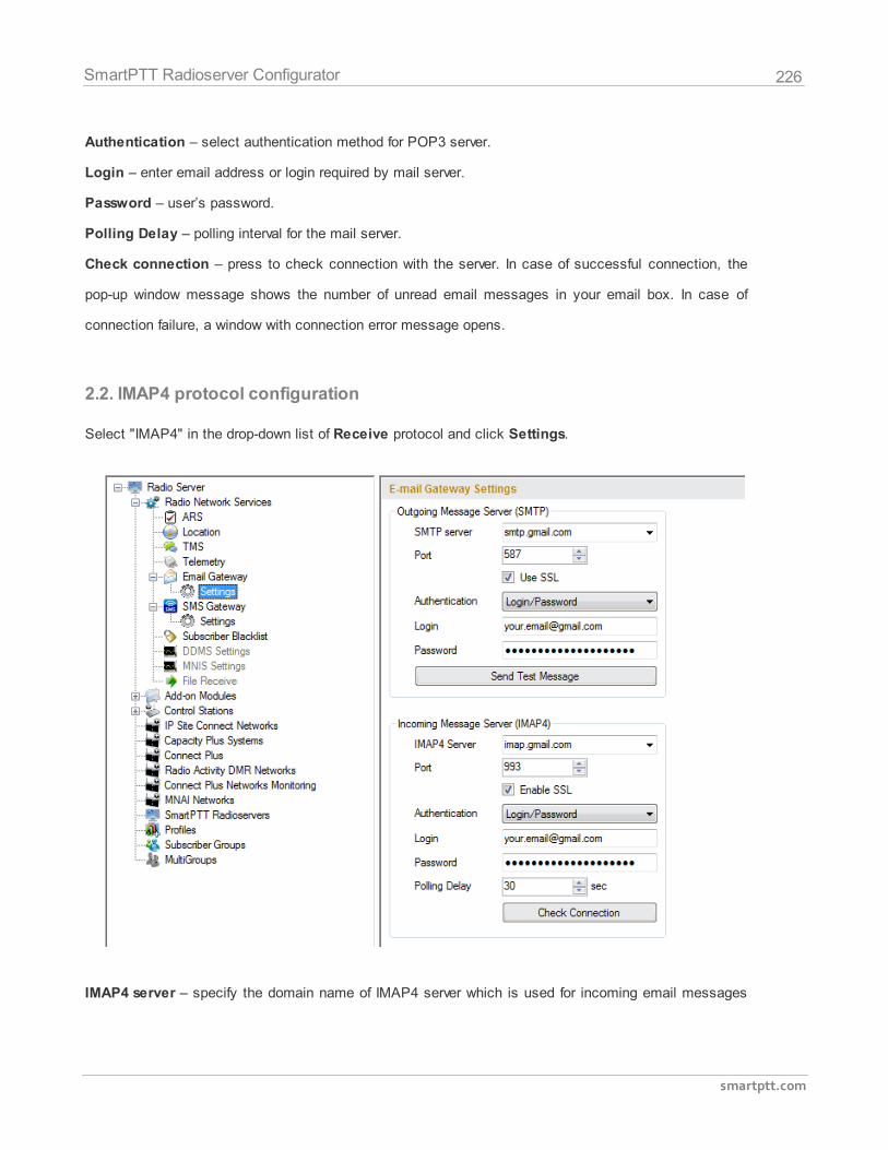
226
smartptt.com
SmartPTT Radioserver Configurator
Authentication – select authentication method for POP3 server.
Login – enter email address or login required by mail server.
Password – user’s password.
Polling Delay – polling interval for the mail server.
Check connection – press to check connection with the server. In case of successful connection, the
pop-up window message shows the number of unread email messages in your email box. In case of
connection failure, a window with connection error message opens.
2.2. IMAP4 protocol configuration
Select "IMAP4" in the drop-down list of Receive protocol and click Settings.
IMAP4 server – specify the domain name of IMAP4 server which is used for incoming email messages
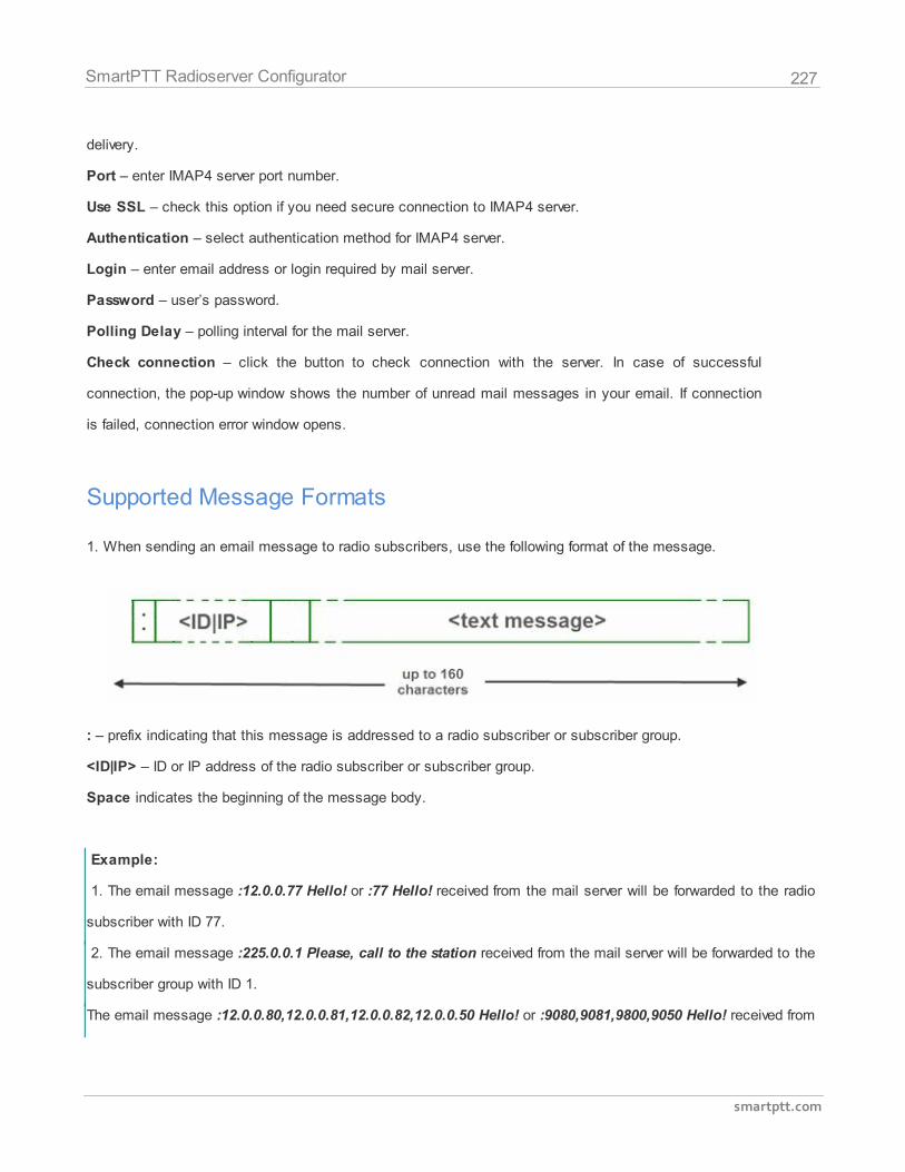
227
smartptt.com
SmartPTT Radioserver Configurator
delivery.
Port – enter IMAP4 server port number.
Use SSL – check this option if you need secure connection to IMAP4 server.
Authentication – select authentication method for IMAP4 server.
Login – enter email address or login required by mail server.
Password – user’s password.
Polling Delay – polling interval for the mail server.
Check connection – click the button to check connection with the server. In case of successful
connection, the pop-up window shows the number of unread mail messages in your email. If connection
is failed, connection error window opens.
Supported Message Formats
1. When sending an email message to radio subscribers, use the following format of the message.
: – prefix indicating that this message is addressed to a radio subscriber or subscriber group.
<ID|IP> – ID or IP address of the radio subscriber or subscriber group.
Space indicates the beginning of the message body.
Example:
1. The email message :12.0.0.77 Hello! or :77 Hello! received from the mail server will be forwarded to the radio
subscriber with ID 77.
2. The email message :225.0.0.1 Please, call to the station received from the mail server will be forwarded to the
subscriber group with ID 1.
The email message :12.0.0.80,12.0.0.81,12.0.0.82,12.0.0.50 Hello! or :9080,9081,9800,9050 Hello! received from
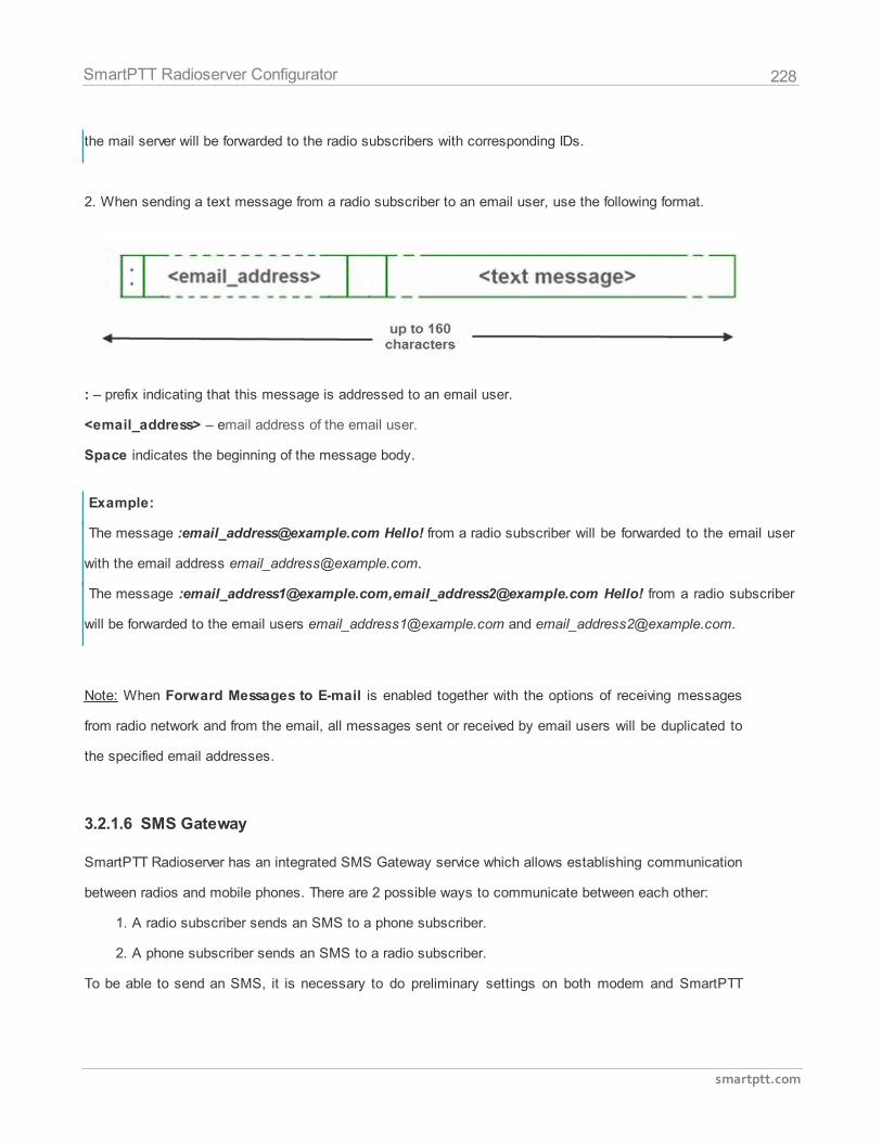
228
smartptt.com
SmartPTT Radioserver Configurator
the mail server will be forwarded to the radio subscribers with corresponding IDs.
2. When sending a text message from a radio subscriber to an email user, use the following format.
: – prefix indicating that this message is addressed to an email user.
<email_address> – email address of the email user.
Space indicates the beginning of the message body.
Example:
The message :[email protected] Hello! from a radio subscriber will be forwarded to the email user
with the email address [email protected].
The message :[email protected],[email protected] Hello! from a radio subscriber
will be forwarded to the email users [email protected] and [email protected].
Note: When Forward Messages to E-mail is enabled together with the options of receiving messages
from radio network and from the email, all messages sent or received by email users will be duplicated to
the specified email addresses.
3.2.1.6 SMS Gateway
SmartPTT Radioserver has an integrated SMS Gateway service which allows establishing communication
between radios and mobile phones. There are 2 possible ways to communicate between each other:
1. A radio subscriber sends an SMS to a phone subscriber.
2. A phone subscriber sends an SMS to a radio subscriber.
To be able to send an SMS, it is necessary to do preliminary settings on both modem and SmartPTT
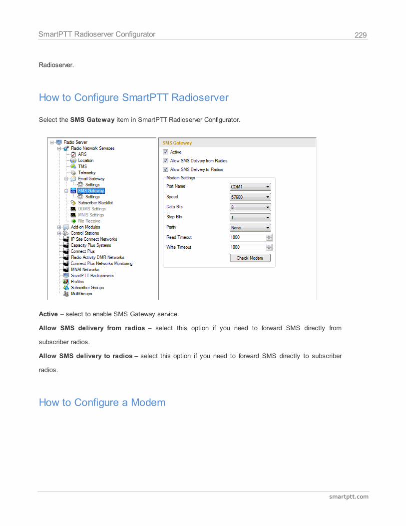
229
smartptt.com
SmartPTT Radioserver Configurator
Radioserver.
How to Configure SmartPTT Radioserver
Select the SMS Gateway item in SmartPTT Radioserver Configurator.
Active – select to enable SMS Gateway service.
Allow SMS delivery from radios – select this option if you need to forward SMS directly from
subscriber radios.
Allow SMS delivery to radios – select this option if you need to forward SMS directly to subscriber
radios.
How to Configure a Modem
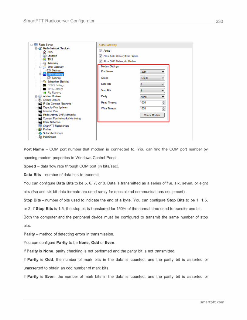
230
smartptt.com
SmartPTT Radioserver Configurator
Port Name – COM port number that modem is connected to. You can find the COM port number by
opening modem properties in Windows Control Panel.
Speed – data flow rate through COM port (in bits/sec).
Data Bits – number of data bits to transmit.
You can configure Data Bits to be 5, 6, 7, or 8. Data is transmitted as a series of five, six, seven, or eight
bits (five and six bit data formats are used rarely for specialized communications equipment).
Stop Bits – number of bits used to indicate the end of a byte. You can configure Stop Bits to be 1, 1.5,
or 2. If Stop Bits is 1.5, the stop bit is transferred for 150% of the normal time used to transfer one bit.
Both the computer and the peripheral device must be configured to transmit the same number of stop
bits.
Parity – method of detecting errors in transmission.
You can configure Parity to be None, Odd or Even.
If Parity is None, parity checking is not performed and the parity bit is not transmitted.
If Parity is Odd, the number of mark bits in the data is counted, and the parity bit is asserted or
unasserted to obtain an odd number of mark bits.
If Parity is Even, the number of mark bits in the data is counted, and the parity bit is asserted or
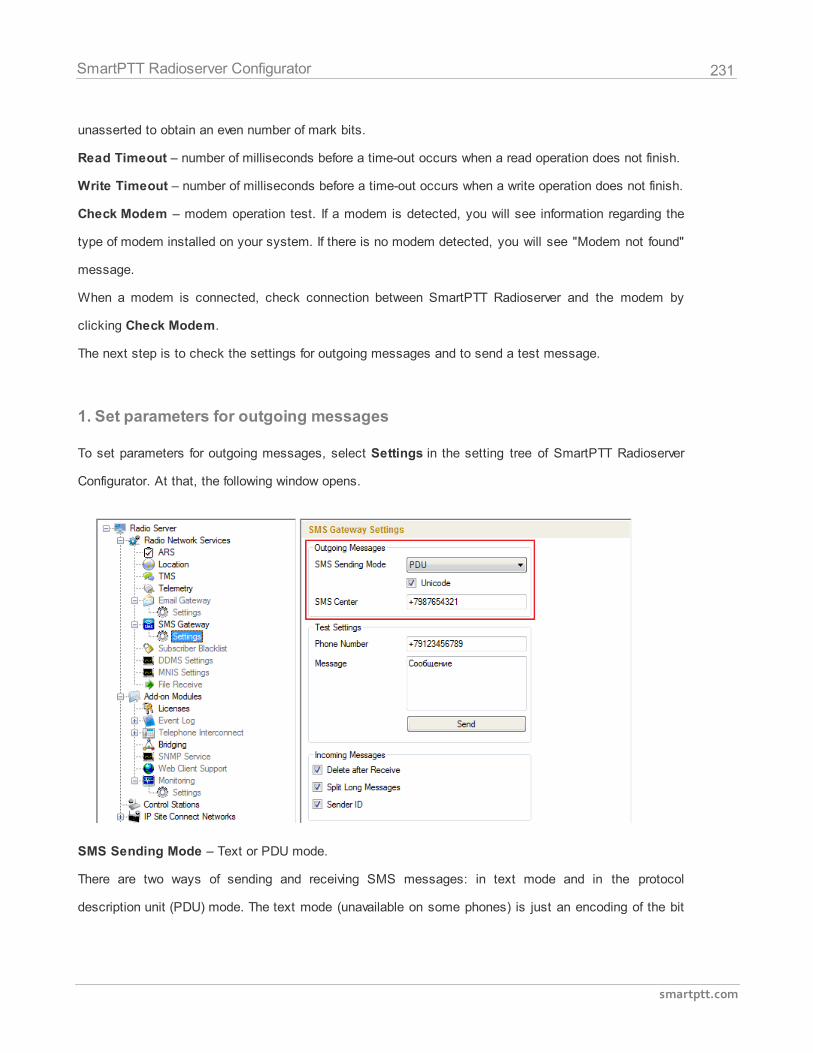
231
smartptt.com
SmartPTT Radioserver Configurator
unasserted to obtain an even number of mark bits.
Read Timeout – number of milliseconds before a time-out occurs when a read operation does not finish.
Write Timeout – number of milliseconds before a time-out occurs when a write operation does not finish.
Check Modem – modem operation test. If a modem is detected, you will see information regarding the
type of modem installed on your system. If there is no modem detected, you will see "Modem not found"
message.
When a modem is connected, check connection between SmartPTT Radioserver and the modem by
clicking Check Modem.
The next step is to check the settings for outgoing messages and to send a test message.
1. Set parameters for outgoing messages
To set parameters for outgoing messages, select Settings in the setting tree of SmartPTT Radioserver
Configurator. At that, the following window opens.
SMS Sending Mode – Text or PDU mode.
There are two ways of sending and receiving SMS messages: in text mode and in the protocol
description unit (PDU) mode. The text mode (unavailable on some phones) is just an encoding of the bit
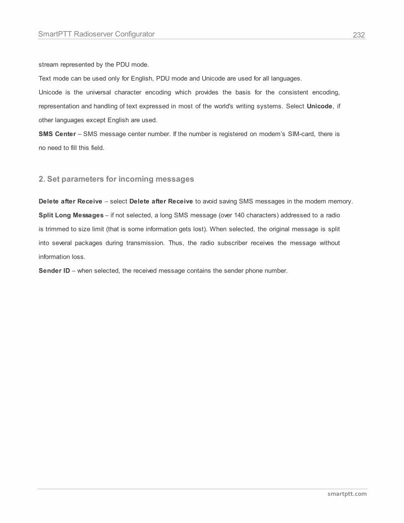
232
smartptt.com
SmartPTT Radioserver Configurator
stream represented by the PDU mode.
Text mode can be used only for English, PDU mode and Unicode are used for all languages.
Unicode is the universal character encoding which provides the basis for the consistent encoding,
representation and handling of text expressed in most of the world's writing systems. Select Unicode, if
other languages except English are used.
SMS Center – SMS message center number. If the number is registered on modem’s SIM-card, there is
no need to fill this field.
2. Set parameters for incoming messages
Delete after Receive – select Delete after Receive to avoid saving SMS messages in the modem memory.
Split Long Messages – if not selected, a long SMS message (over 140 characters) addressed to a radio
is trimmed to size limit (that is some information gets lost). When selected, the original message is split
into several packages during transmission. Thus, the radio subscriber receives the message without
information loss.
Sender ID – when selected, the received message contains the sender phone number.
233
smartptt.com
SmartPTT Radioserver Configurator
3. Run tests on SMS sending
Make sure SMS messages can be sent to recipients from SmartPTT Radioserver. Use the Test Settings
option to do it.
First, in the field Phone Number specify the phone number where you will send the test message.
Second, enter the text of the message in the field Message. And then click Send.
If the message is successfully sent, you will get a confirmation notification.
When modem is selected and test message is successfully sent, then save setting and restart the
radioserver .
After radioserver is restarted, Check modem and Send (test message) will be unavailable. It means that now
you can send SMS messages from the radio and to the radio.
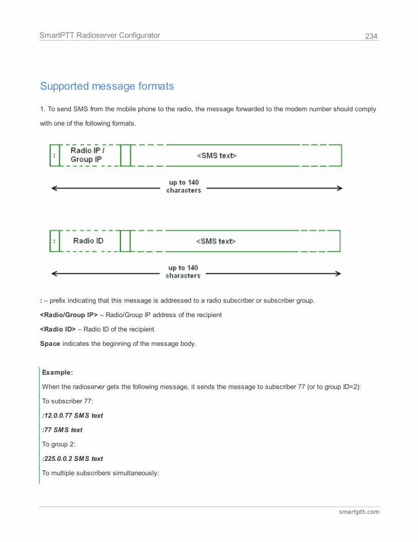
234
smartptt.com
SmartPTT Radioserver Configurator
Supported message formats
1. To send SMS from the mobile phone to the radio, the message forwarded to the modem number should comply
with one of the following formats.
: – prefix indicating that this message is addressed to a radio subscriber or subscriber group.
<Radio/Group IP> – Radio/Group IP address of the recipient
<Radio ID> – Radio ID of the recipient
Space indicates the beginning of the message body.
Example:
When the radioserver gets the following message, it sends the message to subscriber 77 (or to group ID=2):
To subscriber 77:
:12.0.0.77 SMS text
:77 SMS text
To group 2:
:225.0.0.2 SMS text
To multiple subscribers simultaneously:
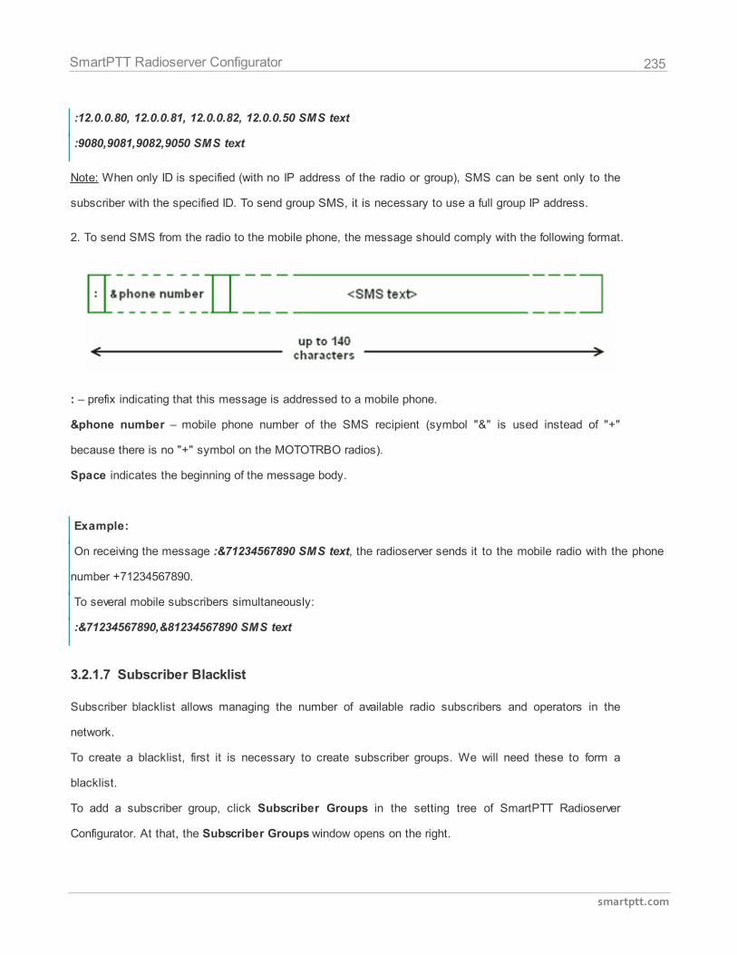
235
smartptt.com
SmartPTT Radioserver Configurator
:12.0.0.80, 12.0.0.81, 12.0.0.82, 12.0.0.50 SMS text
:9080,9081,9082,9050 SMS text
Note: When only ID is specified (with no IP address of the radio or group), SMS can be sent only to the
subscriber with the specified ID. To send group SMS, it is necessary to use a full group IP address.
2. To send SMS from the radio to the mobile phone, the message should comply with the following format.
: – prefix indicating that this message is addressed to a mobile phone.
&phone number – mobile phone number of the SMS recipient (symbol "&" is used instead of "+"
because there is no "+" symbol on the MOTOTRBO radios).
Space indicates the beginning of the message body.
Example:
On receiving the message :&71234567890 SMS text, the radioserver sends it to the mobile radio with the phone
number +71234567890.
To several mobile subscribers simultaneously:
:&71234567890,&81234567890 SMS text
3.2.1.7 Subscriber Blacklist
Subscriber blacklist allows managing the number of available radio subscribers and operators in the
network.
To create a blacklist, first it is necessary to create subscriber groups. We will need these to form a
blacklist.
To add a subscriber group, click Subscriber Groups in the setting tree of SmartPTT Radioserver
Configurator. At that, the Subscriber Groups window opens on the right.
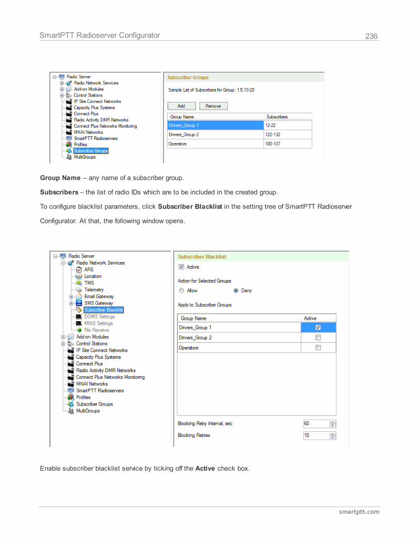
236
smartptt.com
SmartPTT Radioserver Configurator
Group Name – any name of a subscriber group.
Subscribers – the list of radio IDs which are to be included in the created group.
To configure blacklist parameters, click Subscriber Blacklist in the setting tree of SmartPTT Radioserver
Configurator. At that, the following window opens.
Enable subscriber blacklist service by ticking off the Active check box.
237
smartptt.com
SmartPTT Radioserver Configurator
Note: Subscriber Blacklist allows not only blocking certain radios, but also creating the so-called
"whitelist" of radios that are allowed in the radio network. In the latter case all other radios, that is not
included in the whitelist, will be blocked.
To block certain groups of subscribers, choose Deny and select groups which are not permitted to
communicate in MOTOTRBO network.
To allow certain groups of subscribers to communicate in MOTOTRBO network, that is to create a
whitelist, select Allow and mark those groups which will be available in radio network when all other
radios are blocked.
Blocking Retry Interval, sec – sets a minimum time period for sending a command to block the radio
added in the blacklist.
Blocking Retries – number of retries to send the Block command to the radio before confirmation
comes.
To save changes, click Save and then restart SmartPTT Radioserver .
If a radio is in the blacklist and MOTORBO control station is used (MOTOTRBO control station, Capacity
Plus system), then the radio will be completely unavailable. When the radio is unavailable, some actions
are still available: Monitoring, Radio Check and Radio Unblocking. The dispatcher can remove the
block from the radio by sending the "Unblock" command. To enable the radio without dispatcher's help,
just read the codeplug of the radio in MOTOTRBO Customer Programming Software (called MOTOTRBO
CPS) and then write the settings to the codeplug.
To be able to process the Radio Disable command, the radio must have the Radio Disable Decode
parameter selected in the codeplug. You can find it in MOTOTRBO CPS, in the Signaling Systems
section. If Radio Disable Decode is not selected, the radio can't be blocked even if it is in the blacklist.
When direct IP connection is used (for example, IP Site Connect) in MOTOTRBO network, radio blocking
allows to block the channel only. At that, "Channel Denied" is displayed on the radio screen. The radio
can change the channel and resume its operation. To enable the blocked channel, the dispatcher should
send the "Unblock" command to the radio. To enable the radio without dispatcher's help, delete the
blocked channel and create the channel equal to the deleted one.
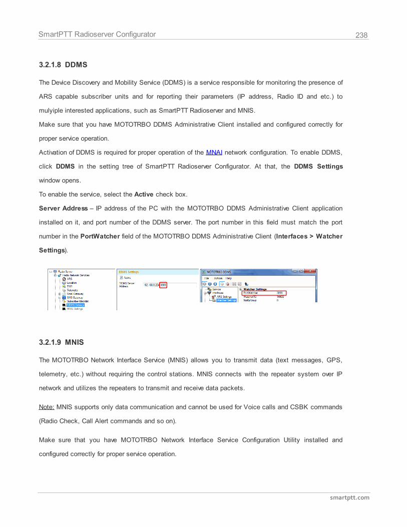
238
smartptt.com
SmartPTT Radioserver Configurator
3.2.1.8 DDMS
The Device Discovery and Mobility Service (DDMS) is a service responsible for monitoring the presence of
ARS capable subscriber units and for reporting their parameters (IP address, Radio ID and etc.) to
mulyiple interested applications, such as SmartPTT Radioserver and MNIS.
Make sure that you have MOTOTRBO DDMS Administrative Client installed and configured correctly for
proper service operation.
Activation of DDMS is required for proper operation of the MNAI network configuration. To enable DDMS,
click DDMS in the setting tree of SmartPTT Radioserver Configurator. At that, the DDMS Settings
window opens.
To enable the service, select the Active check box.
Server Address – IP address of the PC with the MOTOTRBO DDMS Administrative Client application
installed on it, and port number of the DDMS server. The port number in this field must match the port
number in the PortWatcher field of the MOTOTRBO DDMS Administrative Client (Interfaces > Watcher
Settings).
3.2.1.9 MNIS
The MOTOTRBO Network Interface Service (MNIS) allows you to transmit data (text messages, GPS,
telemetry, etc.) without requiring the control stations. MNIS connects with the repeater system over IP
network and utilizes the repeaters to transmit and receive data packets.
Note: MNIS supports only data communication and cannot be used for Voice calls and CSBK commands
(Radio Check, Call Alert commands and so on).
Make sure that you have MOTOTRBO Network Interface Service Configuration Utility installed and
configured correctly for proper service operation.
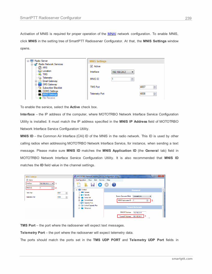
239
smartptt.com
SmartPTT Radioserver Configurator
Activation of MNIS is required for proper operation of the MNAI network configuration. To enable MNIS,
click MNIS in the setting tree of SmartPTT Radioserver Configurator. At that, the MNIS Settings window
opens.
To enable the service, select the Active check box.
Interface – the IP address of the computer, where MOTOTRBO Network Interface Service Configuration
Utility is installed. It must match the IP address specified in the MNIS IP Address field of MOTOTRBO
Network Interface Service Configuration Utility.
MNIS ID – the Common Air Interface (CAI) ID of the MNIS in the radio network. This ID is used by other
calling radios when addressing MOTOTRBO Network Interface Service, for instance, when sending a text
message. Please make sure MNIS ID matches the MNIS Application ID (the General tab) field in
MOTOTRBO Network Interface Service Configuration Utility. It is also recommended that MNIS ID
matches the ID field value in the channel settings.
TMS Port – the port where the radioserver will expect text messages.
Telemetry Port – the port where the radioserver will expect telemetry data.
The ports should match the ports set in the TMS UDP PORT and Telemetry UDP Port fields in
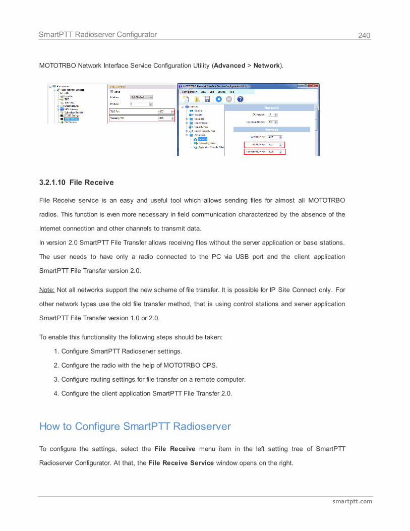
240
smartptt.com
SmartPTT Radioserver Configurator
MOTOTRBO Network Interface Service Configuration Utility (Advanced > Network).
3.2.1.10 File Receive
File Receive service is an easy and useful tool which allows sending files for almost all MOTOTRBO
radios. This function is even more necessary in field communication characterized by the absence of the
Internet connection and other channels to transmit data.
In version 2.0 SmartPTT File Transfer allows receiving files without the server application or base stations.
The user needs to have only a radio connected to the PC via USB port and the client application
SmartPTT File Transfer version 2.0.
Note: Not all networks support the new scheme of file transfer. It is possible for IP Site Connect only. For
other network types use the old file transfer method, that is using control stations and server application
SmartPTT File Transfer version 1.0 or 2.0.
To enable this functionality the following steps should be taken:
1. Configure SmartPTT Radioserver settings.
2. Configure the radio with the help of MOTOTRBO CPS.
3. Configure routing settings for file transfer on a remote computer.
4. Configure the client application SmartPTT File Transfer 2.0.
How to Configure SmartPTT Radioserver
To configure the settings, select the File Receive menu item in the left setting tree of SmartPTT
Radioserver Configurator. At that, the File Receive Service window opens on the right.
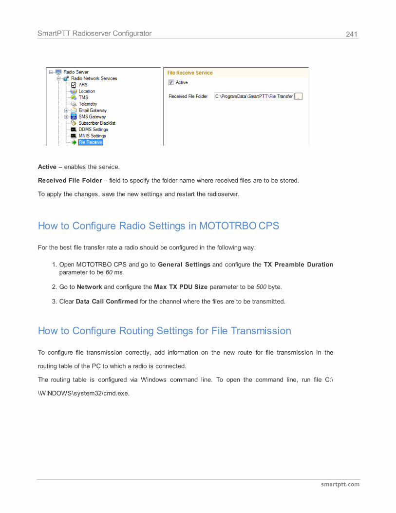
241
smartptt.com
SmartPTT Radioserver Configurator
Active – enables the service.
Received File Folder – field to specify the folder name where received files are to be stored.
To apply the changes, save the new settings and restart the radioserver.
How to Configure Radio Settings in MOTOTRBO CPS
For the best file transfer rate a radio should be configured in the following way:
1. Open MOTOTRBO CPS and go to General Settings and configure the TX Preamble Durationparameter to be 60 ms.
2. Go to Network and configure the Max TX PDU Size parameter to be 500 byte.
3. Clear Data Call Confirmed for the channel where the files are to be transmitted.
How to Configure Routing Settings for File Transmission
To configure file transmission correctly, add information on the new route for file transmission in the
routing table of the PC to which a radio is connected.
The routing table is configured via Windows command line. To open the command line, run file C:\
\WINDOWS\system32\cmd.exe.
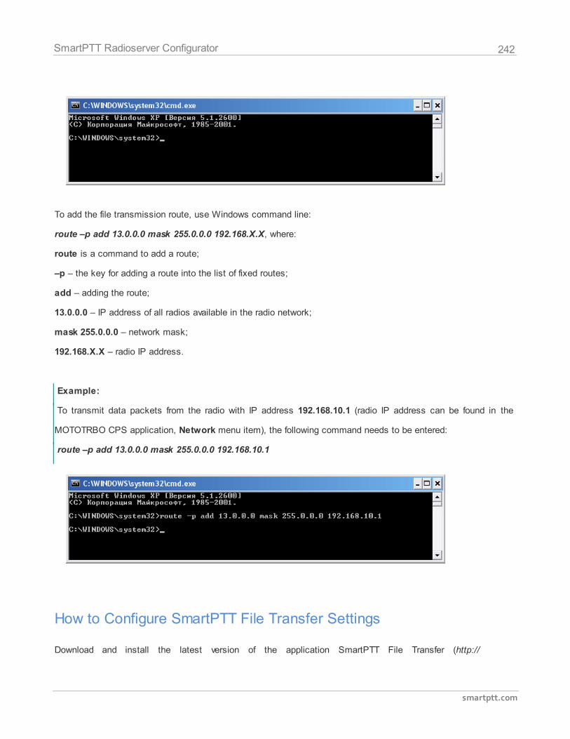
242
smartptt.com
SmartPTT Radioserver Configurator
To add the file transmission route, use Windows command line:
route –p add 13.0.0.0 mask 255.0.0.0 192.168.Х.Х, where:
route is a command to add a route;
–p – the key for adding a route into the list of fixed routes;
add – adding the route;
13.0.0.0 – IP address of all radios available in the radio network;
mask 255.0.0.0 – network mask;
192.168.Х.Х – radio IP address.
Example:
To transmit data packets from the radio with IP address 192.168.10.1 (radio IP address can be found in the
MOTOTRBO CPS application, Network menu item), the following command needs to be entered:
route –p add 13.0.0.0 mask 255.0.0.0 192.168.10.1
How to Configure SmartPTT File Transfer Settings
Download and install the latest version of the application SmartPTT File Transfer (http://
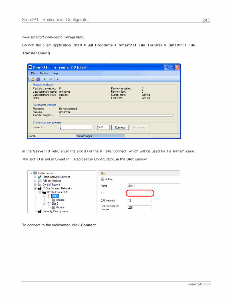
243
smartptt.com
SmartPTT Radioserver Configurator
www.smartptt.com/demo_versija.html).
Launch the client application (Start > All Programs > SmartPTT File Transfer > SmartPTT File
Transfer Client).
In the Server ID field, enter the slot ID of the IP Site Connect, which will be used for file transmission.
The slot ID is set in Smart PTT Radioserver Configurator, in the Slot window.
To connect to the radioserver, click Connect.
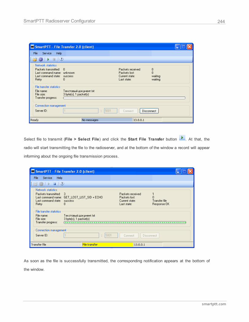
244
smartptt.com
SmartPTT Radioserver Configurator
Select file to transmit (File > Select File) and click the Start File Transfer button . At that, the
radio will start transmitting the file to the radioserver, and at the bottom of the window a record will appear
informing about the ongoing file transmission process.
As soon as the file is successfully transmitted, the corresponding notification appears at the bottom of
the window.
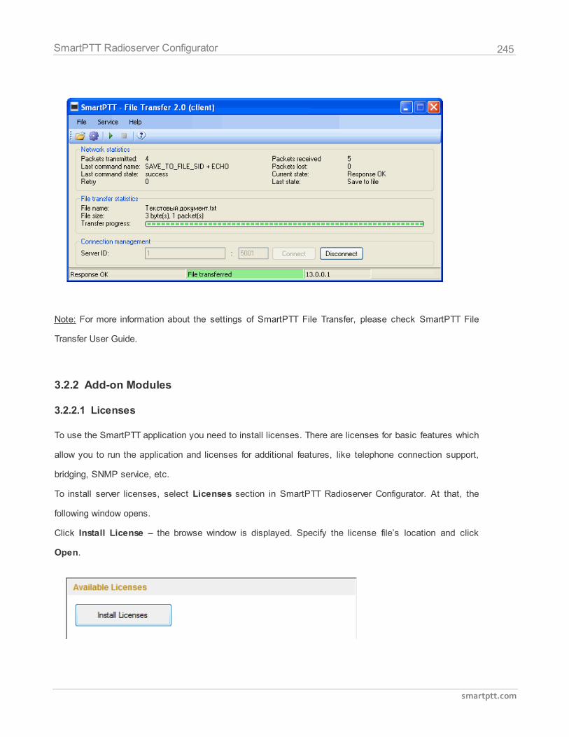
245
smartptt.com
SmartPTT Radioserver Configurator
Note: For more information about the settings of SmartPTT File Transfer, please check SmartPTT File
Transfer User Guide.
3.2.2 Add-on Modules
3.2.2.1 Licenses
To use the SmartPTT application you need to install licenses. There are licenses for basic features which
allow you to run the application and licenses for additional features, like telephone connection support,
bridging, SNMP service, etc.
To install server licenses, select Licenses section in SmartPTT Radioserver Configurator. At that, the
following window opens.
Click Install License – the browse window is displayed. Specify the license file’s location and click
Open.
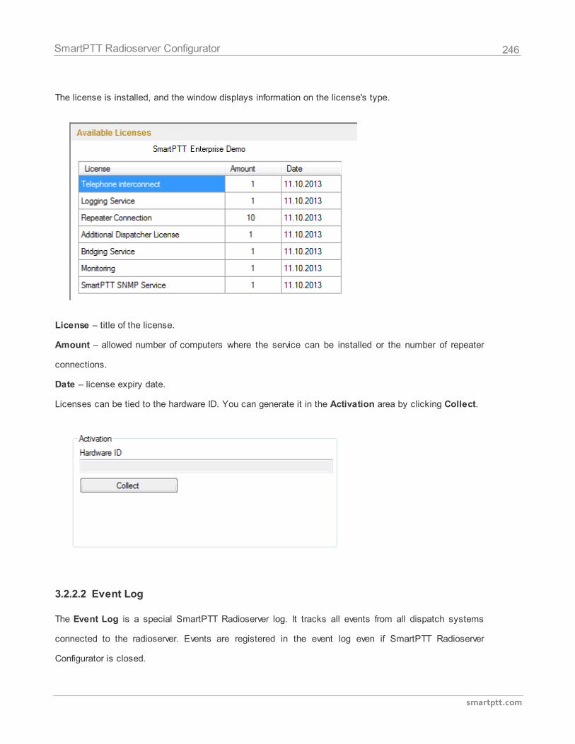
246
smartptt.com
SmartPTT Radioserver Configurator
The license is installed, and the window displays information on the license's type.
License – title of the license.
Amount – allowed number of computers where the service can be installed or the number of repeater
connections.
Date – license expiry date.
Licenses can be tied to the hardware ID. You can generate it in the Activation area by clicking Collect.
3.2.2.2 Event Log
The Event Log is a special SmartPTT Radioserver log. It tracks all events from all dispatch systems
connected to the radioserver. Events are registered in the event log even if SmartPTT Radioserver
Configurator is closed.
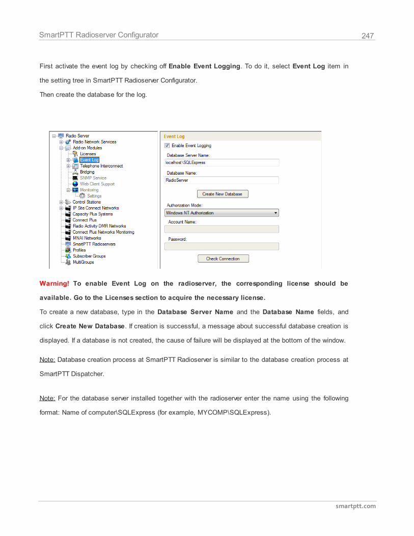
247
smartptt.com
SmartPTT Radioserver Configurator
First activate the event log by checking off Enable Event Logging. To do it, select Event Log item in
the setting tree in SmartPTT Radioserver Configurator.
Then create the database for the log.
Warning! To enable Event Log on the radioserver, the corresponding license should be
available. Go to the Licenses section to acquire the necessary license.
To create a new database, type in the Database Server Name and the Database Name fields, and
click Create New Database. If creation is successful, a message about successful database creation is
displayed. If a database is not created, the cause of failure will be displayed at the bottom of the window.
Note: Database creation process at SmartPTT Radioserver is similar to the database creation process at
SmartPTT Dispatcher.
Note: For the database server installed together with the radioserver enter the name using the following
format: Name of computer\SQLExpress (for example, MYCOMP\SQLExpress).
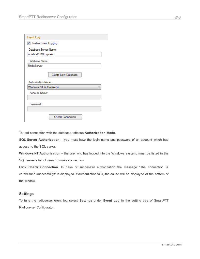
248
smartptt.com
SmartPTT Radioserver Configurator
To test connection with the database, choose Authorization Mode.
SQL Server Authorization – you must have the login name and password of an account which has
access to the SQL server.
Windows NT Authorization – the user who has logged into the Windows system, must be listed in the
SQL server’s list of users to make connection.
Click Check Connection. In case of successful authorization the message "The connection is
established successfully!" is displayed. If authorization fails, the cause will be displayed at the bottom of
the window.
Settings
To tune the radioserver event log select Settings under Event Log in the setting tree of SmartPTT
Radioserver Configurator.
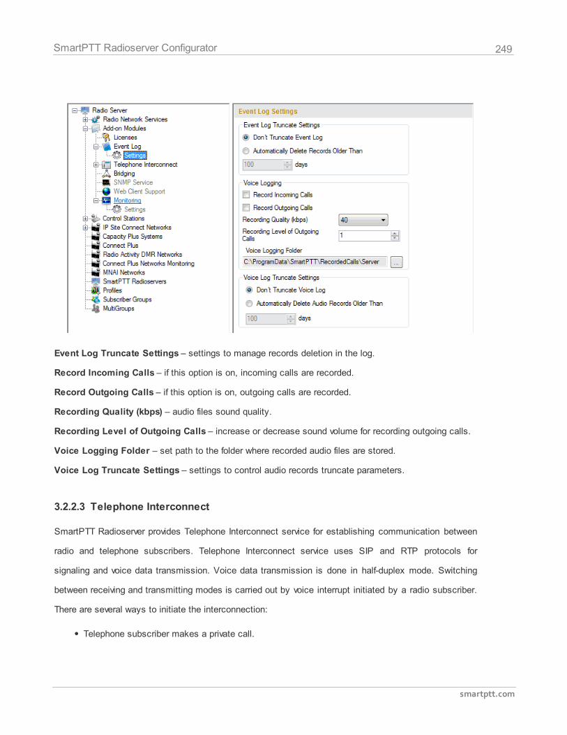
249
smartptt.com
SmartPTT Radioserver Configurator
Event Log Truncate Settings – settings to manage records deletion in the log.
Record Incoming Calls – if this option is on, incoming calls are recorded.
Record Outgoing Calls – if this option is on, outgoing calls are recorded.
Recording Quality (kbps) – audio files sound quality.
Recording Level of Outgoing Calls – increase or decrease sound volume for recording outgoing calls.
Voice Logging Folder – set path to the folder where recorded audio files are stored.
Voice Log Truncate Settings – settings to control audio records truncate parameters.
3.2.2.3 Telephone Interconnect
SmartPTT Radioserver provides Telephone Interconnect service for establishing communication between
radio and telephone subscribers. Telephone Interconnect service uses SIP and RTP protocols for
signaling and voice data transmission. Voice data transmission is done in half-duplex mode. Switching
between receiving and transmitting modes is carried out by voice interrupt initiated by a radio subscriber.
There are several ways to initiate the interconnection:
Telephone subscriber makes a private call.
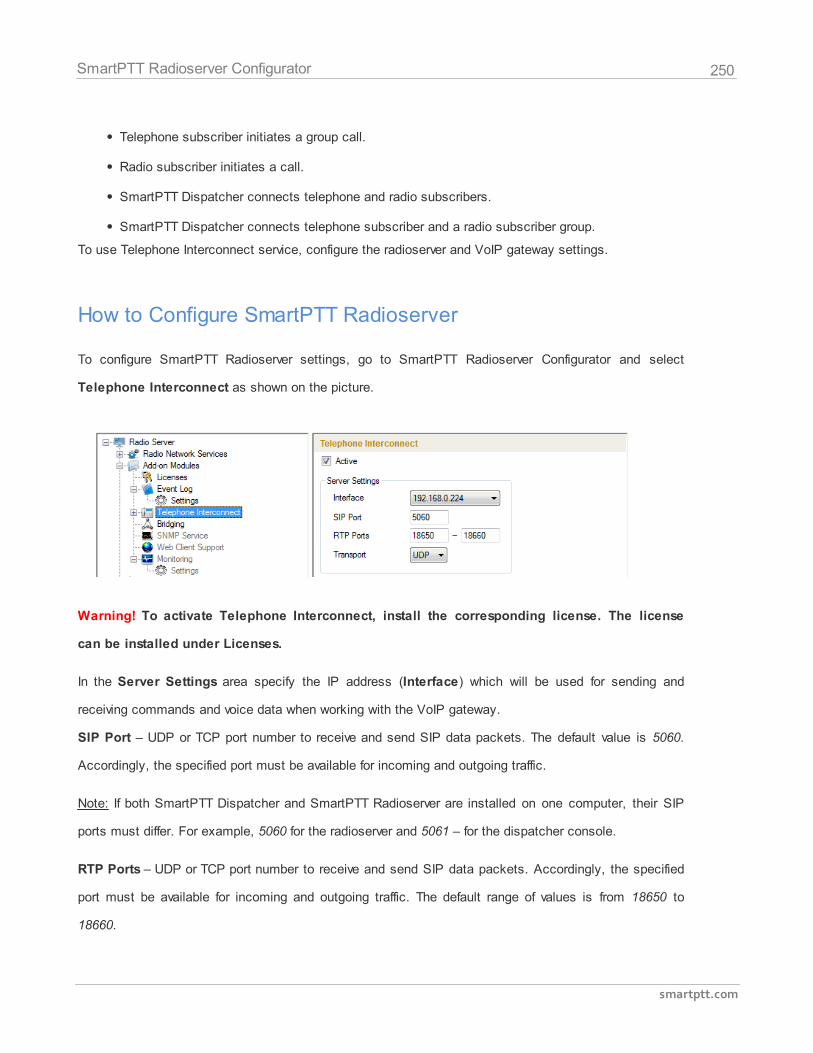
250
smartptt.com
SmartPTT Radioserver Configurator
Telephone subscriber initiates a group call.
Radio subscriber initiates a call.
SmartPTT Dispatcher connects telephone and radio subscribers.
SmartPTT Dispatcher connects telephone subscriber and a radio subscriber group.
To use Telephone Interconnect service, configure the radioserver and VoIP gateway settings.
How to Configure SmartPTT Radioserver
To configure SmartPTT Radioserver settings, go to SmartPTT Radioserver Configurator and select
Telephone Interconnect as shown on the picture.
Warning! To activate Telephone Interconnect, install the corresponding license. The license
can be installed under Licenses.
In the Server Settings area specify the IP address (Interface) which will be used for sending and
receiving commands and voice data when working with the VoIP gateway.
SIP Port – UDP or TCP port number to receive and send SIP data packets. The default value is 5060.
Accordingly, the specified port must be available for incoming and outgoing traffic.
Note: If both SmartPTT Dispatcher and SmartPTT Radioserver are installed on one computer, their SIP
ports must differ. For example, 5060 for the radioserver and 5061 – for the dispatcher console.
RTP Ports – UDP or TCP port number to receive and send SIP data packets. Accordingly, the specified
port must be available for incoming and outgoing traffic. The default range of values is from 18650 to
18660.
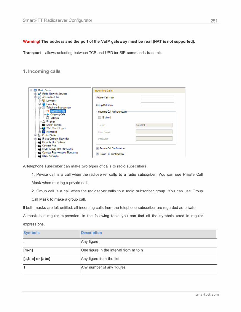
251
smartptt.com
SmartPTT Radioserver Configurator
Warning! The address and the port of the VoIP gateway must be real (NAT is not supported).
Transport – allows selecting between TCP and UPD for SIP commands transmit.
1. Incoming calls
A telephone subscriber can make two types of calls to radio subscribers.
1. Private call is a call when the radioserver calls to a radio subscriber. You can use Private Call
Mask when making a private call.
2. Group call is a call when the radioserver calls to a radio subscriber group. You can use Group
Call Mask to make a group call.
If both masks are left unfilled, all incoming calls from the telephone subscriber are regarded as private.
A mask is a regular expression. In the following table you can find all the symbols used in regular
expressions.
Symbols Description
. Any figure
[m-n] One figure in the interval from m to n
[a,b,c] or [abc] Any figure from the list
T Any number of any figures
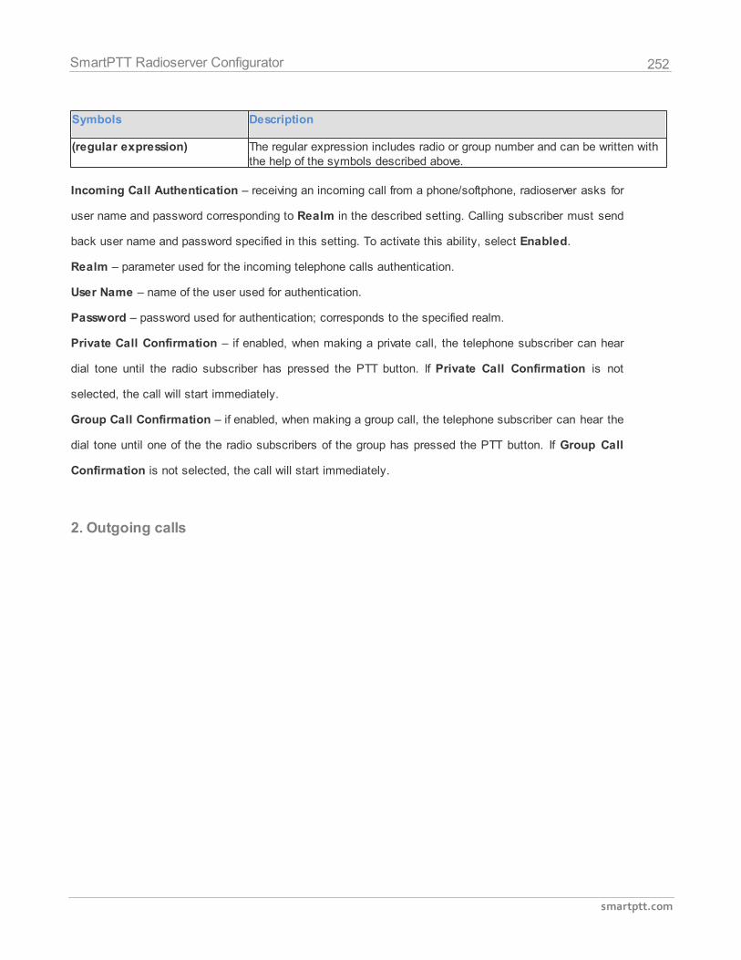
252
smartptt.com
SmartPTT Radioserver Configurator
Symbols Description
(regular expression) The regular expression includes radio or group number and can be written withthe help of the symbols described above.
Incoming Call Authentication – receiving an incoming call from a phone/softphone, radioserver asks for
user name and password corresponding to Realm in the described setting. Calling subscriber must send
back user name and password specified in this setting. To activate this ability, select Enabled.
Realm – parameter used for the incoming telephone calls authentication.
User Name – name of the user used for authentication.
Password – password used for authentication; corresponds to the specified realm.
Private Call Confirmation – if enabled, when making a private call, the telephone subscriber can hear
dial tone until the radio subscriber has pressed the PTT button. If Private Call Confirmation is not
selected, the call will start immediately.
Group Call Confirmation – if enabled, when making a group call, the telephone subscriber can hear the
dial tone until one of the the radio subscribers of the group has pressed the PTT button. If Group Call
Confirmation is not selected, the call will start immediately.
2. Outgoing calls
253
smartptt.com
SmartPTT Radioserver Configurator
Allow Calls to Default VoIP Gateway – if enabled, radio subscriber calls to telephone subscribers are
made automatically, using all the data given, such as IP Address of the automatic exchange, Source
and Destination Masks, Dialing Rules. If the option is not selected, radio subscribers will need to enter
the IP address and the full number of the telephone subscriber to make a call.
IP Address – IP address of the automatic exchange.
Source Mask – must correspond to the source mask specified in the automatic exchange. It includes
only figures, for example, 32%15, where % is the number of the radio subscriber.
Destination Mask – contains only figures, for example, 32%15, where % is the dialed telephone number.
It is used to speed up dialing of the telephone number.
TMS Prefix is used for making a call to a telephone subscriber with the help of a text message sent from
a radio. TMS Prefix can contain any symbol, which is available on the radio keyboard. Figures following
the specified prefix are regarded as the telephone subscriber's number.
254
smartptt.com
SmartPTT Radioserver Configurator
Outgoing Call Authentication – the setting includes parameters required for outgoing call
authentication. If Realm is left blank, the specified user name and password are used in response to any
authentication request from the called party. Otherwise, Realm is checked whether it corresponds to the
requesting user name and password. If it matches, user name and password are sent. If not, the
authentication is failed immediately.
Realm – if the value is set, SmartPTT Radioserver responds to authentication requests with the
matching Realm value. If the value is not set, SmartPTT Radioserver sends user name and password
given in response to any authentication request.
User Name – user name used for authentication.
Password – password used for authentication.
Subscriber Name at Private Call – name of the radio subscriber which will be shown to the telephone
subscriber. % will be replaced automatically by the radio number.
Subscriber Name at Group Call – name of the radio subscriber group which will be shown to the
telephone subscriber. % will be replaced automatically by the radio number.
3. Telephone Interconnect settings
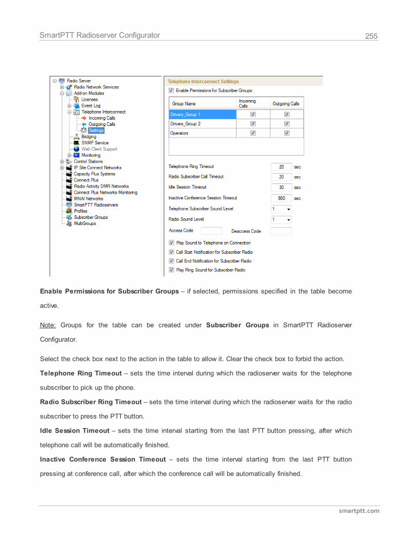
255
smartptt.com
SmartPTT Radioserver Configurator
Enable Permissions for Subscriber Groups – if selected, permissions specified in the table become
active.
Note: Groups for the table can be created under Subscriber Groups in SmartPTT Radioserver
Configurator.
Select the check box next to the action in the table to allow it. Clear the check box to forbid the action.
Telephone Ring Timeout – sets the time interval during which the radioserver waits for the telephone
subscriber to pick up the phone.
Radio Subscriber Ring Timeout – sets the time interval during which the radioserver waits for the radio
subscriber to press the PTT button.
Idle Session Timeout – sets the time interval starting from the last PTT button pressing, after which
telephone call will be automatically finished.
Inactive Conference Session Timeout – sets the time interval starting from the last PTT button
pressing at conference call, after which the conference call will be automatically finished.
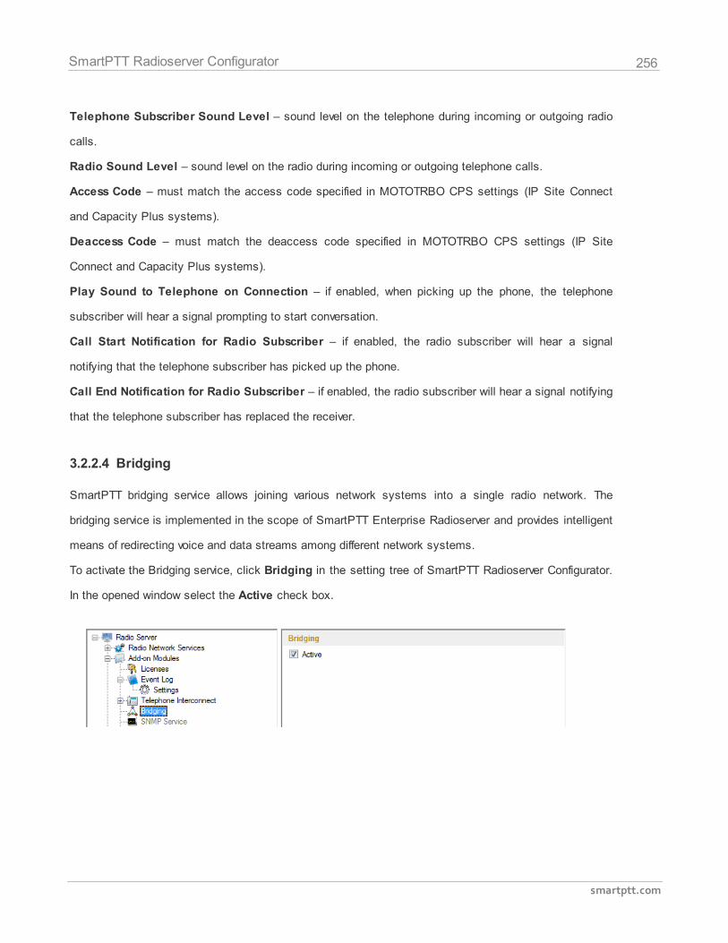
256
smartptt.com
SmartPTT Radioserver Configurator
Telephone Subscriber Sound Level – sound level on the telephone during incoming or outgoing radio
calls.
Radio Sound Level – sound level on the radio during incoming or outgoing telephone calls.
Access Code – must match the access code specified in MOTOTRBO CPS settings (IP Site Connect
and Capacity Plus systems).
Deaccess Code – must match the deaccess code specified in MOTOTRBO CPS settings (IP Site
Connect and Capacity Plus systems).
Play Sound to Telephone on Connection – if enabled, when picking up the phone, the telephone
subscriber will hear a signal prompting to start conversation.
Call Start Notification for Radio Subscriber – if enabled, the radio subscriber will hear a signal
notifying that the telephone subscriber has picked up the phone.
Call End Notification for Radio Subscriber – if enabled, the radio subscriber will hear a signal notifying
that the telephone subscriber has replaced the receiver.
3.2.2.4 Bridging
SmartPTT bridging service allows joining various network systems into a single radio network. The
bridging service is implemented in the scope of SmartPTT Enterprise Radioserver and provides intelligent
means of redirecting voice and data streams among different network systems.
To activate the Bridging service, click Bridging in the setting tree of SmartPTT Radioserver Configurator.
In the opened window select the Active check box.
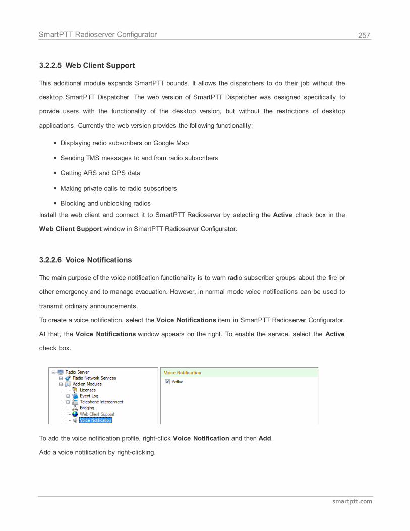
257
smartptt.com
SmartPTT Radioserver Configurator
3.2.2.5 Web Client Support
This additional module expands SmartPTT bounds. It allows the dispatchers to do their job without the
desktop SmartPTT Dispatcher. The web version of SmartPTT Dispatcher was designed specifically to
provide users with the functionality of the desktop version, but without the restrictions of desktop
applications. Currently the web version provides the following functionality:
Displaying radio subscribers on Google Map
Sending TMS messages to and from radio subscribers
Getting ARS and GPS data
Making private calls to radio subscribers
Blocking and unblocking radios
Install the web client and connect it to SmartPTT Radioserver by selecting the Active check box in the
Web Client Support window in SmartPTT Radioserver Configurator.
3.2.2.6 Voice Notifications
The main purpose of the voice notification functionality is to warn radio subscriber groups about the fire or
other emergency and to manage evacuation. However, in normal mode voice notifications can be used to
transmit ordinary announcements.
To create a voice notification, select the Voice Notifications item in SmartPTT Radioserver Configurator.
At that, the Voice Notifications window appears on the right. To enable the service, select the Active
check box.
To add the voice notification profile, right-click Voice Notification and then Add.
Add a voice notification by right-clicking.
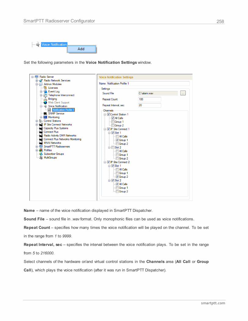
258
smartptt.com
SmartPTT Radioserver Configurator
Set the following parameters in the Voice Notification Settings window.
Name – name of the voice notification displayed in SmartPTT Dispatcher.
Sound File – sound file in .wav format. Only monophonic files can be used as voice notifications.
Repeat Count – specifies how many times the voice notification will be played on the channel. To be set
in the range from 1 to 9999.
Repeat Interval, sec – specifies the interval between the voice notification plays. To be set in the range
from 5 to 216000.
Select channels of the hardware or/and virtual control stations in the Channels area (All Call or Group
Call), which plays the voice notification (after it was run in SmartPTT Dispatcher).
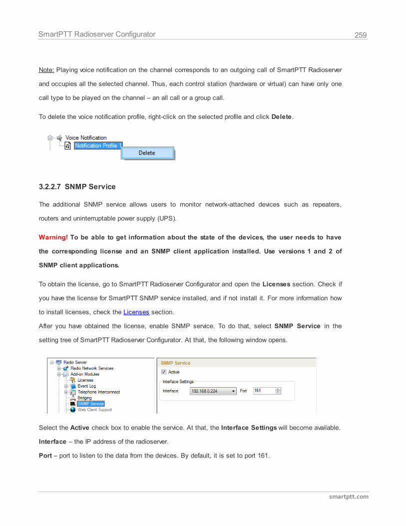
259
smartptt.com
SmartPTT Radioserver Configurator
Note: Playing voice notification on the channel corresponds to an outgoing call of SmartPTT Radioserver
and occupies all the selected channel. Thus, each control station (hardware or virtual) can have only one
call type to be played on the channel – an all call or a group call.
To delete the voice notification profile, right-click on the selected profile and click Delete.
3.2.2.7 SNMP Service
The additional SNMP service allows users to monitor network-attached devices such as repeaters,
routers and uninterruptable power supply (UPS).
Warning! To be able to get information about the state of the devices, the user needs to have
the corresponding license and an SNMP client application installed. Use versions 1 and 2 of
SNMP client applications.
To obtain the license, go to SmartPTT Radioserver Configurator and open the Licenses section. Check if
you have the license for SmartPTT SNMP service installed, and if not install it. For more information how
to install licenses, check the Licenses section.
After you have obtained the license, enable SNMP service. To do that, select SNMP Service in the
setting tree of SmartPTT Radioserver Configurator. At that, the following window opens.
Select the Active check box to enable the service. At that, the Interface Settings will become available.
Interface – the IP address of the radioserver.
Port – port to listen to the data from the devices. By default, it is set to port 161.
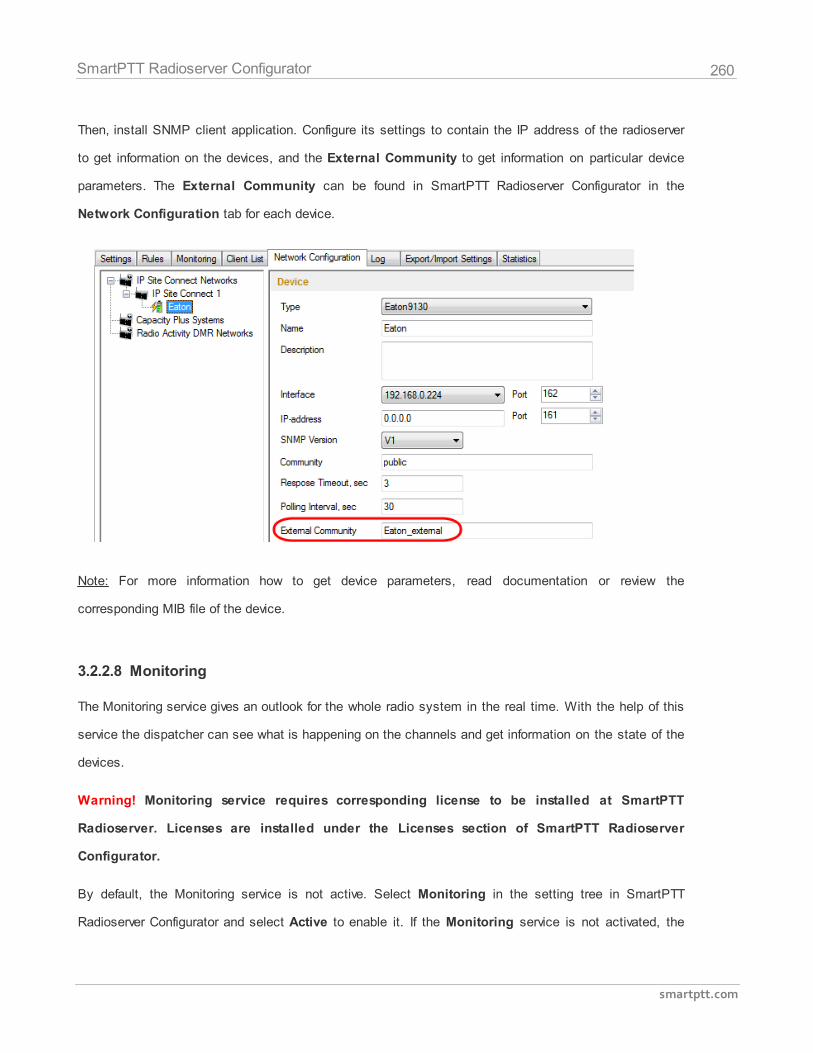
260
smartptt.com
SmartPTT Radioserver Configurator
Then, install SNMP client application. Configure its settings to contain the IP address of the radioserver
to get information on the devices, and the External Community to get information on particular device
parameters. The External Community can be found in SmartPTT Radioserver Configurator in the
Network Configuration tab for each device.
Note: For more information how to get device parameters, read documentation or review the
corresponding MIB file of the device.
3.2.2.8 Monitoring
The Monitoring service gives an outlook for the whole radio system in the real time. With the help of this
service the dispatcher can see what is happening on the channels and get information on the state of the
devices.
Warning! Monitoring service requires corresponding license to be installed at SmartPTT
Radioserver. Licenses are installed under the Licenses section of SmartPTT Radioserver
Configurator.
By default, the Monitoring service is not active. Select Monitoring in the setting tree in SmartPTT
Radioserver Configurator and select Active to enable it. If the Monitoring service is not activated, the
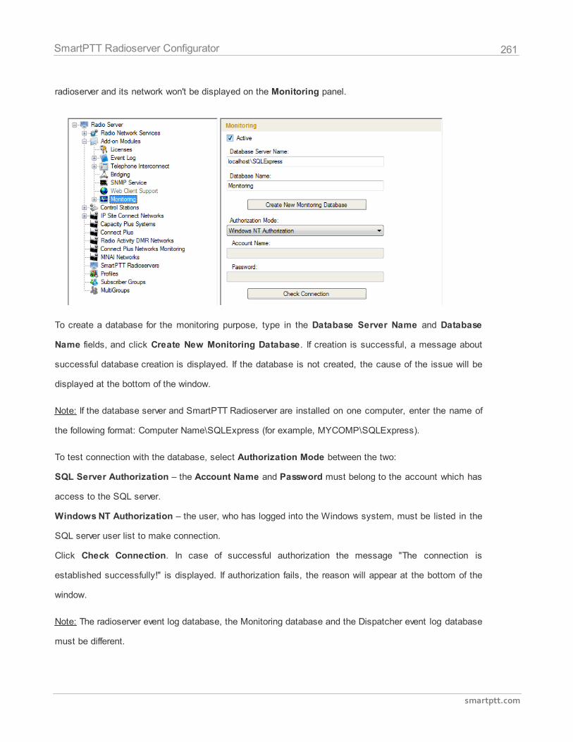
261
smartptt.com
SmartPTT Radioserver Configurator
radioserver and its network won't be displayed on the Monitoring panel.
To create a database for the monitoring purpose, type in the Database Server Name and Database
Name fields, and click Create New Monitoring Database. If creation is successful, a message about
successful database creation is displayed. If the database is not created, the cause of the issue will be
displayed at the bottom of the window.
Note: If the database server and SmartPTT Radioserver are installed on one computer, enter the name of
the following format: Computer Name\SQLExpress (for example, MYCOMP\SQLExpress).
To test connection with the database, select Authorization Mode between the two:
SQL Server Authorization – the Account Name and Password must belong to the account which has
access to the SQL server.
Windows NT Authorization – the user, who has logged into the Windows system, must be listed in the
SQL server user list to make connection.
Click Check Connection. In case of successful authorization the message "The connection is
established successfully!" is displayed. If authorization fails, the reason will appear at the bottom of the
window.
Note: The radioserver event log database, the Monitoring database and the Dispatcher event log database
must be different.
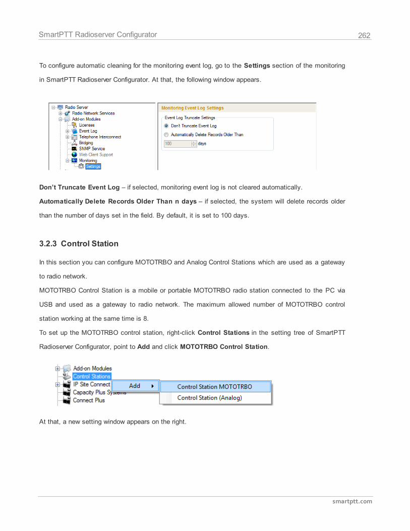
262
smartptt.com
SmartPTT Radioserver Configurator
To configure automatic cleaning for the monitoring event log, go to the Settings section of the monitoring
in SmartPTT Radioserver Configurator. At that, the following window appears.
Don’t Truncate Event Log – if selected, monitoring event log is not cleared automatically.
Automatically Delete Records Older Than n days – if selected, the system will delete records older
than the number of days set in the field. By default, it is set to 100 days.
3.2.3 Control Station
In this section you can configure MOTOTRBO and Analog Control Stations which are used as a gateway
to radio network.
MOTOTRBO Control Station is a mobile or portable MOTOTRBO radio station connected to the PC via
USB and used as a gateway to radio network. The maximum allowed number of MOTOTRBO control
station working at the same time is 8.
To set up the MOTOTRBO control station, right-click Control Stations in the setting tree of SmartPTT
Radioserver Configurator, point to Add and click MOTOTRBO Control Station.
At that, a new setting window appears on the right.
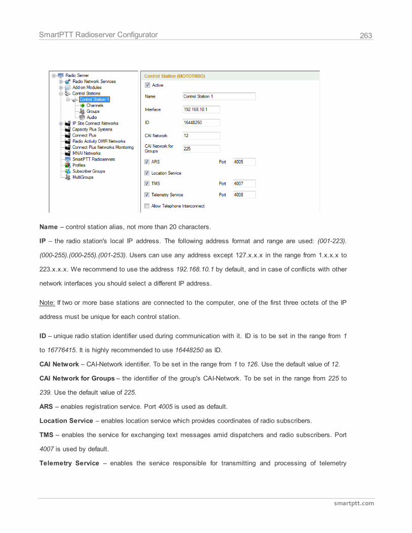
263
smartptt.com
SmartPTT Radioserver Configurator
Name – control station alias, not more than 20 characters.
IP – the radio station's local IP address. The following address format and range are used: (001-223).
(000-255).(000-255).(001-253). Users can use any address except 127.x.x.x in the range from 1.x.x.x to
223.x.x.x. We recommend to use the address 192.168.10.1 by default, and in case of conflicts with other
network interfaces you should select a different IP address.
Note: If two or more base stations are connected to the computer, one of the first three octets of the IP
address must be unique for each control station.
ID – unique radio station identifier used during communication with it. ID is to be set in the range from 1
to 16776415. It is highly recommended to use 16448250 as ID.
CAI Network – CAI-Network identifier. To be set in the range from 1 to 126. Use the default value of 12.
CAI Network for Groups – the identifier of the group's CAI-Network. To be set in the range from 225 to
239. Use the default value of 225.
ARS – enables registration service. Port 4005 is used as default.
Location Service – enables location service which provides coordinates of radio subscribers.
TMS – enables the service for exchanging text messages amid dispatchers and radio subscribers. Port
4007 is used by default.
Telemetry Service – enables the service responsible for transmitting and processing of telemetry
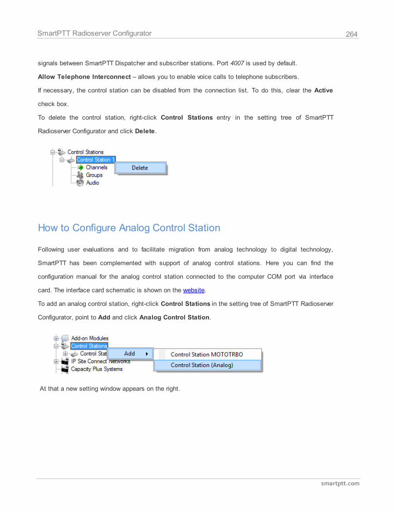
264
smartptt.com
SmartPTT Radioserver Configurator
signals between SmartPTT Dispatcher and subscriber stations. Port 4007 is used by default.
Allow Telephone Interconnect – allows you to enable voice calls to telephone subscribers.
If necessary, the control station can be disabled from the connection list. To do this, clear the Active
check box.
To delete the control station, right-click Control Stations entry in the setting tree of SmartPTT
Radioserver Configurator and click Delete.
How to Configure Analog Control Station
Following user evaluations and to facilitate migration from analog technology to digital technology,
SmartPTT has been complemented with support of analog control stations. Here you can find the
configuration manual for the analog control station connected to the computer COM port via interface
card. The interface card schematic is shown on the website.
To add an analog control station, right-click Control Stations in the setting tree of SmartPTT Radioserver
Configurator, point to Add and click Analog Control Station.
At that a new setting window appears on the right.
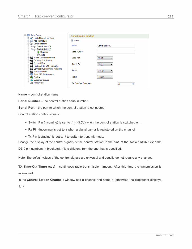
265
smartptt.com
SmartPTT Radioserver Configurator
Name – control station name.
Serial Number – the control station serial number.
Serial Port – the port to which the control station is connected.
Control station control signals:
Switch Pin (incoming) is set to 1 (< -3.0V) when the control station is switched on.
Rx Pin (incoming) is set to 1 when a signal carrier is registered on the channel.
Tx Pin (outgoing) is set to 1 to switch to transmit mode.
Change the display of the control signals of the control station to the pins of the socket RS323 (see the
DE-9 pin numbers in brackets), if it is different from the one that is specified.
Note: The default values of the control signals are universal and usually do not require any changes.
TX Time-Out Timer (sec) – continuous radio transmission timeout. After this time the transmission is
interrupted.
In the Control Station Channels window add a channel and name it (otherwise the dispatcher displays
1:1).
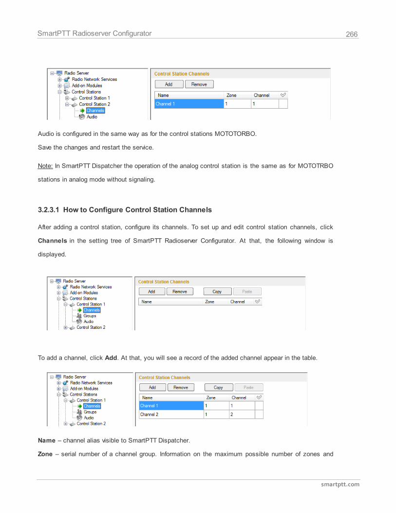
266
smartptt.com
SmartPTT Radioserver Configurator
Audio is configured in the same way as for the control stations MOTOTORBO.
Save the changes and restart the service.
Note: In SmartPTT Dispatcher the operation of the analog control station is the same as for MOTOTRBO
stations in analog mode without signaling.
3.2.3.1 How to Configure Control Station Channels
After adding a control station, configure its channels. To set up and edit control station channels, click
Channels in the setting tree of SmartPTT Radioserver Configurator. At that, the following window is
displayed.
To add a channel, click Add. At that, you will see a record of the added channel appear in the table.
Name – channel alias visible to SmartPTT Dispatcher.
Zone – serial number of a channel group. Information on the maximum possible number of zones and
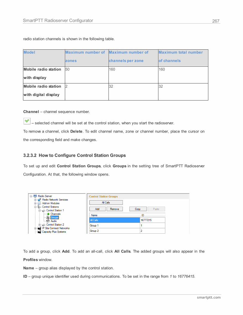
267
smartptt.com
SmartPTT Radioserver Configurator
radio station channels is shown in the following table.
Model Maximum number of
zones
Maximum number of
channels per zone
Maximum total number
of channels
Mobile radio station
with display
50 160 160
Mobile radio station
with digital display
2 32 32
Channel – channel sequence number.
– selected channel will be set at the control station, when you start the radioserver.
To remove a channel, click Delete. To edit channel name, zone or channel number, place the cursor on
the corresponding field and make changes.
3.2.3.2 How to Configure Control Station Groups
To set up and edit Control Station Groups, click Groups in the setting tree of SmartPTT Radioserver
Configuration. At that, the following window opens.
To add a group, click Add. To add an all-call, click All Calls. The added groups will also appear in the
Profiles window.
Name – group alias displayed by the control station.
ID – group unique identifier used during communications. To be set in the range from 1 to 16776415.
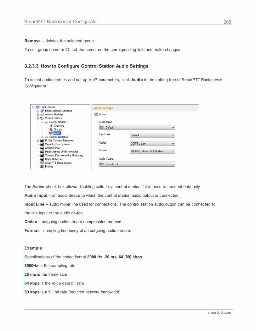
268
smartptt.com
SmartPTT Radioserver Configurator
Remove – deletes the selected group.
To edit group name or ID, set the cursor on the corresponding field and make changes.
3.2.3.3 How to Configure Control Station Audio Settings
To select audio devices and set up VoIP parameters, click Audio in the setting tree of SmartPTT Radioserver
Configurator.
The Active check box allows disabling calls for a control station if it is used to transmit data only.
Audio Input – an audio device to which the control station audio output is connected.
Input Line – audio mixer line used for connections. The control station audio output can be connected to
the line input of the audio device.
Codec – outgoing audio stream compression method.
Format – sampling frequency of an outgoing audio stream.
Example:
Specifications of the codec format 8000 Hz, 20 ms, 64 (89) kbps:
8000Hz is the sampling rate
20 ms is the frame size
64 kbps is the voice data bit rate
89 kbps is a full bit rate (required network bandwidth)
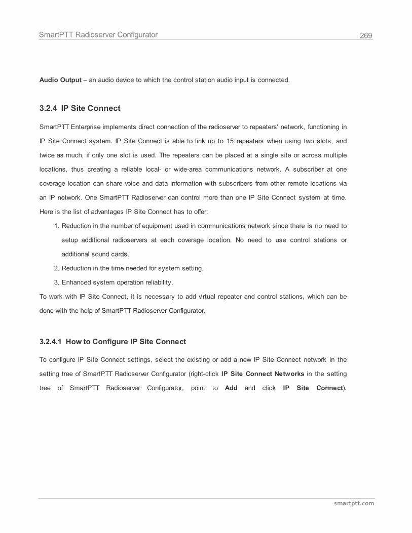
269
smartptt.com
SmartPTT Radioserver Configurator
Audio Output – an audio device to which the control station audio input is connected.
3.2.4 IP Site Connect
SmartPTT Enterprise implements direct connection of the radioserver to repeaters' network, functioning in
IP Site Connect system. IP Site Connect is able to link up to 15 repeaters when using two slots, and
twice as much, if only one slot is used. The repeaters can be placed at a single site or across multiple
locations, thus creating a reliable local- or wide-area communications network. A subscriber at one
coverage location can share voice and data information with subscribers from other remote locations via
an IP network. One SmartPTT Radioserver can control more than one IP Site Connect system at time.
Here is the list of advantages IP Site Connect has to offer:
1. Reduction in the number of equipment used in communications network since there is no need to
setup additional radioservers at each coverage location. No need to use control stations or
additional sound cards.
2. Reduction in the time needed for system setting.
3. Enhanced system operation reliability.
To work with IP Site Connect, it is necessary to add virtual repeater and control stations, which can be
done with the help of SmartPTT Radioserver Configurator.
3.2.4.1 How to Configure IP Site Connect
To configure IP Site Connect settings, select the existing or add a new IP Site Connect network in the
setting tree of SmartPTT Radioserver Configurator (right-click IP Site Connect Networks in the setting
tree of SmartPTT Radioserver Configurator, point to Add and click IP Site Connect).
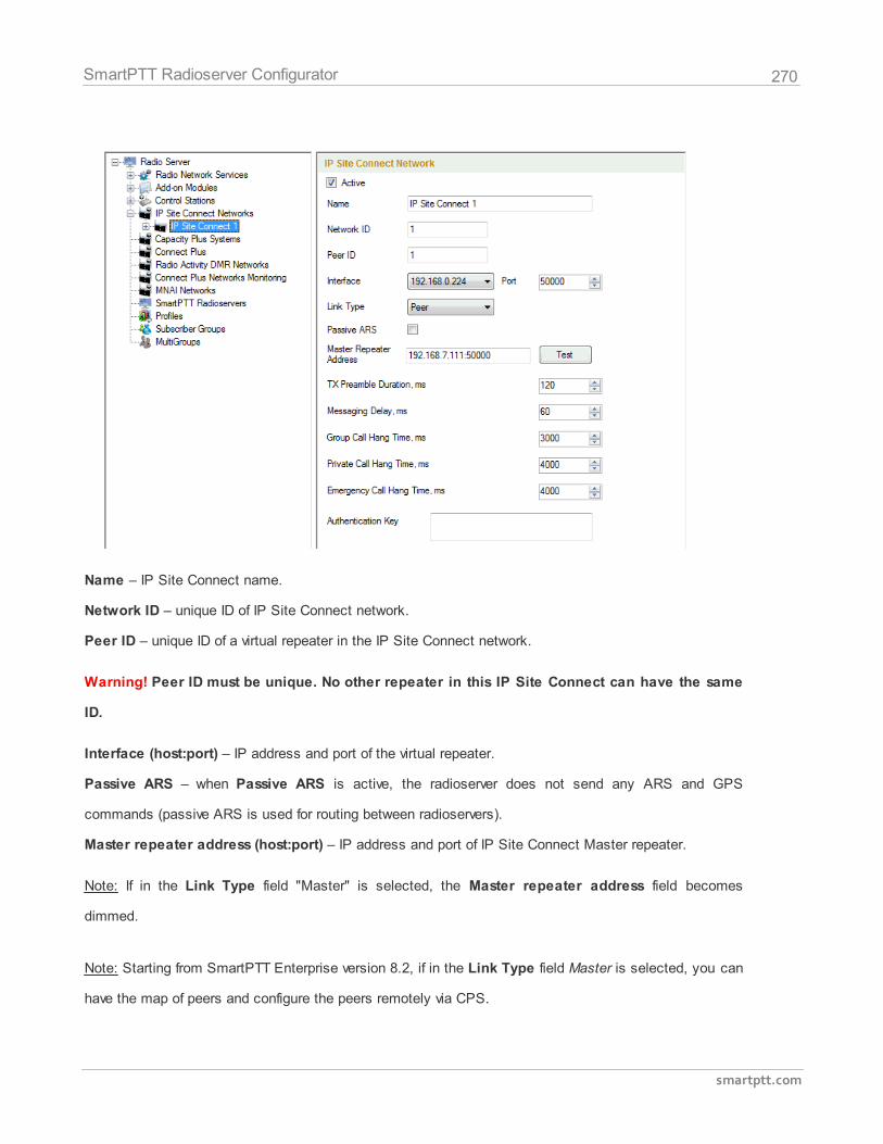
270
smartptt.com
SmartPTT Radioserver Configurator
Name – IP Site Connect name.
Network ID – unique ID of IP Site Connect network.
Peer ID – unique ID of a virtual repeater in the IP Site Connect network.
Warning! Peer ID must be unique. No other repeater in this IP Site Connect can have the same
ID.
Interface (host:port) – IP address and port of the virtual repeater.
Passive ARS – when Passive ARS is active, the radioserver does not send any ARS and GPS
commands (passive ARS is used for routing between radioservers).
Master repeater address (host:port) – IP address and port of IP Site Connect Master repeater.
Note: If in the Link Type field "Master" is selected, the Master repeater address field becomes
dimmed.
Note: Starting from SmartPTT Enterprise version 8.2, if in the Link Type field Master is selected, you can
have the map of peers and configure the peers remotely via CPS.
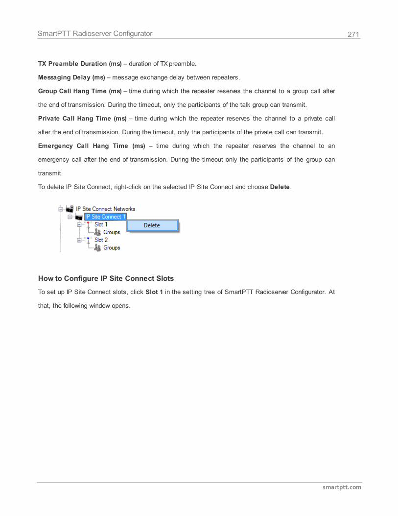
271
smartptt.com
SmartPTT Radioserver Configurator
TX Preamble Duration (ms) – duration of TX preamble.
Messaging Delay (ms) – message exchange delay between repeaters.
Group Call Hang Time (ms) – time during which the repeater reserves the channel to a group call after
the end of transmission. During the timeout, only the participants of the talk group can transmit.
Private Call Hang Time (ms) – time during which the repeater reserves the channel to a private call
after the end of transmission. During the timeout, only the participants of the private call can transmit.
Emergency Call Hang Time (ms) – time during which the repeater reserves the channel to an
emergency call after the end of transmission. During the timeout only the participants of the group can
transmit.
To delete IP Site Connect, right-click on the selected IP Site Connect and choose Delete.
How to Configure IP Site Connect Slots
To set up IP Site Connect slots, click Slot 1 in the setting tree of SmartPTT Radioserver Configurator. At
that, the following window opens.
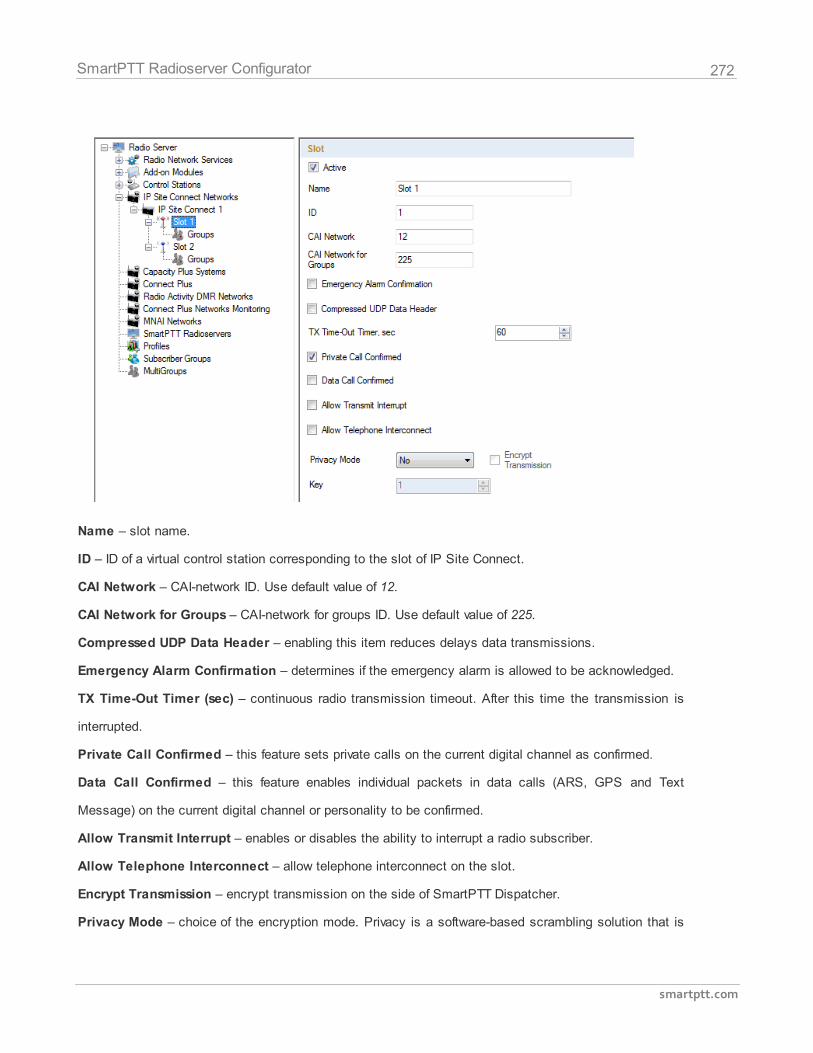
272
smartptt.com
SmartPTT Radioserver Configurator
Name – slot name.
ID – ID of a virtual control station corresponding to the slot of IP Site Connect.
CAI Network – CAI-network ID. Use default value of 12.
CAI Network for Groups – CAI-network for groups ID. Use default value of 225.
Compressed UDP Data Header – enabling this item reduces delays data transmissions.
Emergency Alarm Confirmation – determines if the emergency alarm is allowed to be acknowledged.
TX Time-Out Timer (sec) – continuous radio transmission timeout. After this time the transmission is
interrupted.
Private Call Confirmed – this feature sets private calls on the current digital channel as confirmed.
Data Call Confirmed – this feature enables individual packets in data calls (ARS, GPS and Text
Message) on the current digital channel or personality to be confirmed.
Allow Transmit Interrupt – enables or disables the ability to interrupt a radio subscriber.
Allow Telephone Interconnect – allow telephone interconnect on the slot.
Encrypt Transmission – encrypt transmission on the side of SmartPTT Dispatcher.
Privacy Mode – choice of the encryption mode. Privacy is a software-based scrambling solution that is
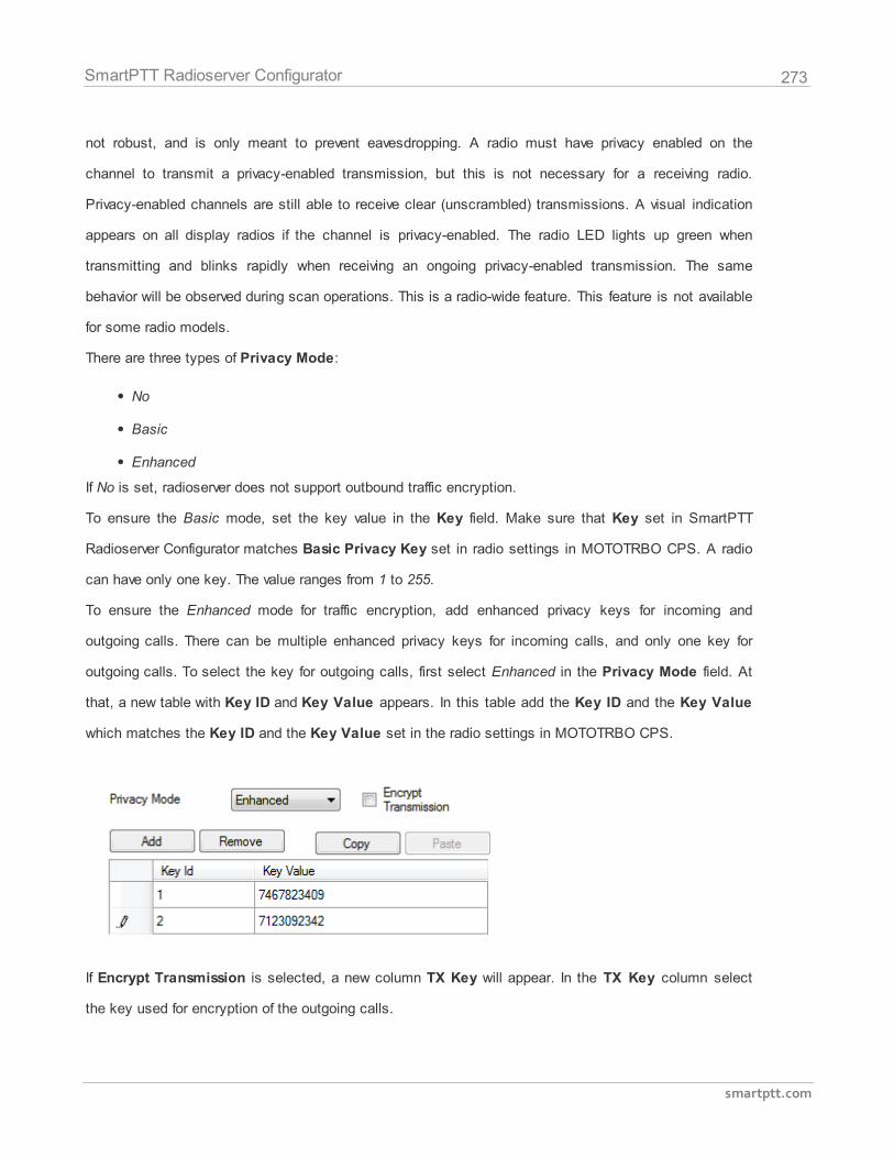
273
smartptt.com
SmartPTT Radioserver Configurator
not robust, and is only meant to prevent eavesdropping. A radio must have privacy enabled on the
channel to transmit a privacy-enabled transmission, but this is not necessary for a receiving radio.
Privacy-enabled channels are still able to receive clear (unscrambled) transmissions. A visual indication
appears on all display radios if the channel is privacy-enabled. The radio LED lights up green when
transmitting and blinks rapidly when receiving an ongoing privacy-enabled transmission. The same
behavior will be observed during scan operations. This is a radio-wide feature. This feature is not available
for some radio models.
There are three types of Privacy Mode:
No
Basic
Enhanced
If No is set, radioserver does not support outbound traffic encryption.
To ensure the Basic mode, set the key value in the Key field. Make sure that Key set in SmartPTT
Radioserver Configurator matches Basic Privacy Key set in radio settings in MOTOTRBO CPS. A radio
can have only one key. The value ranges from 1 to 255.
To ensure the Enhanced mode for traffic encryption, add enhanced privacy keys for incoming and
outgoing calls. There can be multiple enhanced privacy keys for incoming calls, and only one key for
outgoing calls. To select the key for outgoing calls, first select Enhanced in the Privacy Mode field. At
that, a new table with Key ID and Key Value appears. In this table add the Key ID and the Key Value
which matches the Key ID and the Key Value set in the radio settings in MOTOTRBO CPS.
If Encrypt Transmission is selected, a new column TX Key will appear. In the TX Key column select
the key used for encryption of the outgoing calls.
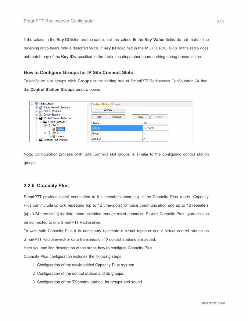
274
smartptt.com
SmartPTT Radioserver Configurator
If the values in the Key ID fields are the same, but the values ??in the Key Value fields do not match, the
receiving radio hears only a distorted voice. If Key ID specified in the MOTOTRBO CPS of the radio does
not match any of the Key IDs specified in the table, the dispatcher hears nothing during transmission.
How to Configure Groups for IP Site Connect Slots
To configure slot groups click Groups in the setting tree of SmartPTT Radioserver Configurator. At that,
the Control Station Groups window opens.
Note: Configuration process of IP Site Connect slot groups is similar to the configuring control station
groups.
3.2.5 Capacity Plus
SmartPTT provides direct connection to the repeaters operating in the Capacity Plus mode. Capacity
Plus can include up to 6 repeaters (up to 12 time-slots) for voice communication and up to 12 repeaters
(up to 24 time-slots) for data communication through revert-channels. Several Capacity Plus systems can
be connected to one SmartPTT Radioserver.
To work with Capacity Plus it is necessary to create a virtual repeater and a virtual control station on
SmartPTT Radioserver.For data transmission TX control stations are added.
Here you can find description of the steps how to configure Capacity Plus.
Capacity Plus configuration includes the following steps:
1. Configuration of the newly added Capacity Plus system.
2. Configuration of the control station and its groups.
3. Configuration of the TX control station, its groups and sound.
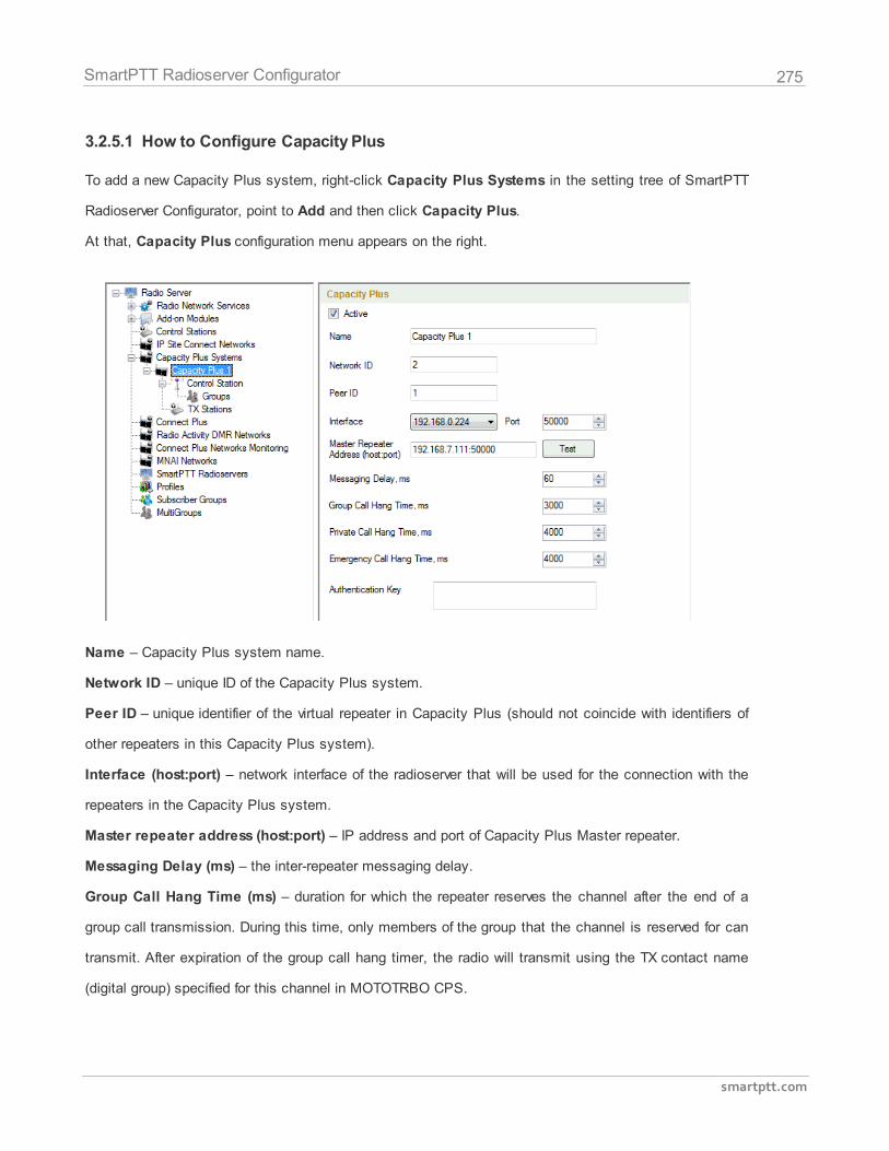
275
smartptt.com
SmartPTT Radioserver Configurator
3.2.5.1 How to Configure Capacity Plus
To add a new Capacity Plus system, right-click Capacity Plus Systems in the setting tree of SmartPTT
Radioserver Configurator, point to Add and then click Capacity Plus.
At that, Capacity Plus configuration menu appears on the right.
Name – Capacity Plus system name.
Network ID – unique ID of the Capacity Plus system.
Peer ID – unique identifier of the virtual repeater in Capacity Plus (should not coincide with identifiers of
other repeaters in this Capacity Plus system).
Interface (host:port) – network interface of the radioserver that will be used for the connection with the
repeaters in the Capacity Plus system.
Master repeater address (host:port) – IP address and port of Capacity Plus Master repeater.
Messaging Delay (ms) – the inter-repeater messaging delay.
Group Call Hang Time (ms) – duration for which the repeater reserves the channel after the end of a
group call transmission. During this time, only members of the group that the channel is reserved for can
transmit. After expiration of the group call hang timer, the radio will transmit using the TX contact name
(digital group) specified for this channel in MOTOTRBO CPS.
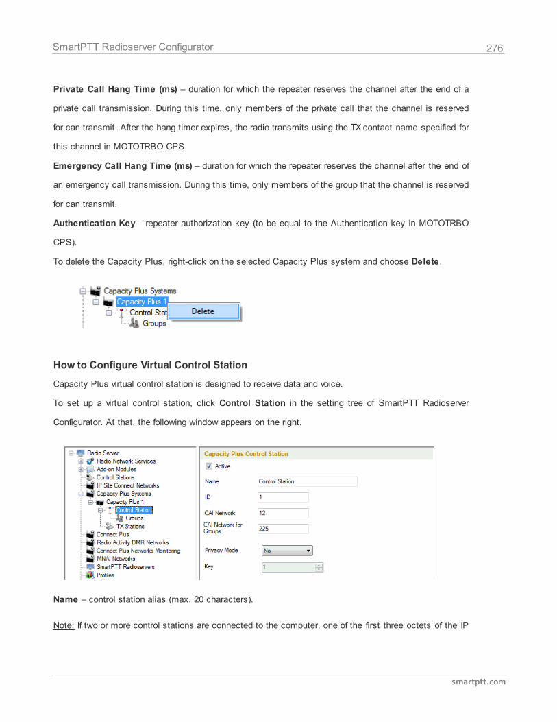
276
smartptt.com
SmartPTT Radioserver Configurator
Private Call Hang Time (ms) – duration for which the repeater reserves the channel after the end of a
private call transmission. During this time, only members of the private call that the channel is reserved
for can transmit. After the hang timer expires, the radio transmits using the TX contact name specified for
this channel in MOTOTRBO CPS.
Emergency Call Hang Time (ms) – duration for which the repeater reserves the channel after the end of
an emergency call transmission. During this time, only members of the group that the channel is reserved
for can transmit.
Authentication Key – repeater authorization key (to be equal to the Authentication key in MOTOTRBO
CPS).
To delete the Capacity Plus, right-click on the selected Capacity Plus system and choose Delete.
How to Configure Virtual Control Station
Capacity Plus virtual control station is designed to receive data and voice.
To set up a virtual control station, click Control Station in the setting tree of SmartPTT Radioserver
Configurator. At that, the following window appears on the right.
Name – control station alias (max. 20 characters).
Note: If two or more control stations are connected to the computer, one of the first three octets of the IP
277
smartptt.com
SmartPTT Radioserver Configurator
address must be unique for each control station.
ID – the unique radio identifier which is used during communication with this radio. It is recommended to
use 16448250 as ID. It is set in the range from 1 to 16776415.
CAI Network – CAI-Network identifier. It is recommended to use the default value 12. It is set in the
range from 1 to 126.
CAI Network for Groups – the identifier of the group's CAI-Network. It is recommended to use the
default value 225. It is set in the range from 225 to 239.
Privacy Mode – choice of the encryption mode. Privacy is a software-based scrambling solution that is
not robust, and is only meant to prevent eavesdropping. A radio must have privacy enabled on the
channel to transmit a privacy-enabled transmission, but this is not necessary for a receiving radio.
Privacy-enabled channels are still able to receive clear (unscrambled) transmissions. A visual indication
appears on all display radios if the channel is privacy-enabled. The radio LED lights up green when
transmitting and blinks rapidly when receiving an ongoing privacy-enabled transmission. The same
behavior will be observed during scan operations. This is a radio-wide feature. This feature is not available
for some radio models.
There are three types of Privacy Mode:
No
Basic
Enhanced
If No is set, radioserver does not support outbound traffic encryption.
To ensure the Basic mode, set the key value in the Key field. Make sure that Key set in SmartPTT
Radioserver Configurator matches Basic Privacy Key set in radio settings in MOTOTRBO CPS. A radio
can have only one key. The value ranges from 1 to 255.
To ensure the Enhanced mode for traffic encryption, multiple enhanced privacy keys can be added.
Select Enhanced in the Privacy Mode field; a new table with Key ID and Key Value appears. In this
table add the Key ID and the Key Value which matches the Key ID and the Key Value set in the radio
settings in MOTOTRBO CPS.
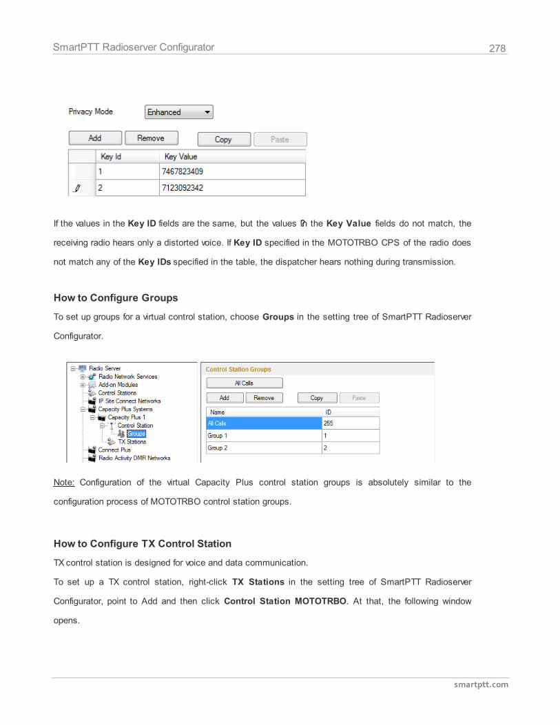
278
smartptt.com
SmartPTT Radioserver Configurator
If the values in the Key ID fields are the same, but the values ??in the Key Value fields do not match, the
receiving radio hears only a distorted voice. If Key ID specified in the MOTOTRBO CPS of the radio does
not match any of the Key IDs specified in the table, the dispatcher hears nothing during transmission.
How to Configure Groups
To set up groups for a virtual control station, choose Groups in the setting tree of SmartPTT Radioserver
Configurator.
Note: Configuration of the virtual Capacity Plus control station groups is absolutely similar to the
configuration process of MOTOTRBO control station groups.
How to Configure TX Control Station
TX control station is designed for voice and data communication.
To set up a TX control station, right-click ТХ Stations in the setting tree of SmartPTT Radioserver
Configurator, point to Add and then click Control Station MOTOTRBO. At that, the following window
opens.
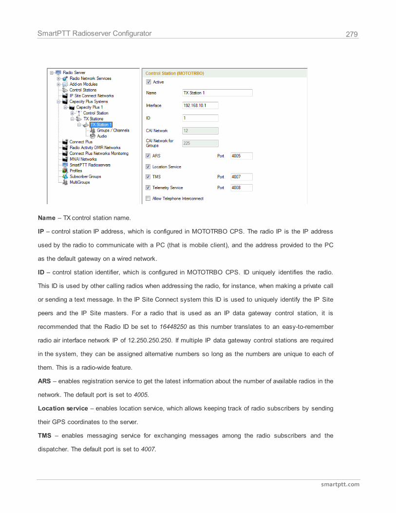
279
smartptt.com
SmartPTT Radioserver Configurator
Name – TX control station name.
IP – control station IP address, which is configured in MOTOTRBO CPS. The radio IP is the IP address
used by the radio to communicate with a PC (that is mobile client), and the address provided to the PC
as the default gateway on a wired network.
ID – control station identifier, which is configured in MOTOTRBO CPS. ID uniquely identifies the radio.
This ID is used by other calling radios when addressing the radio, for instance, when making a private call
or sending a text message. In the IP Site Connect system this ID is used to uniquely identify the IP Site
peers and the IP Site masters. For a radio that is used as an IP data gateway control station, it is
recommended that the Radio ID be set to 16448250 as this number translates to an easy-to-remember
radio air interface network IP of 12.250.250.250. If multiple IP data gateway control stations are required
in the system, they can be assigned alternative numbers so long as the numbers are unique to each of
them. This is a radio-wide feature.
ARS – enables registration service to get the latest information about the number of available radios in the
network. The default port is set to 4005.
Location service – enables location service, which allows keeping track of radio subscribers by sending
their GPS coordinates to the server.
TMS – enables messaging service for exchanging messages among the radio subscribers and the
dispatcher. The default port is set to 4007.
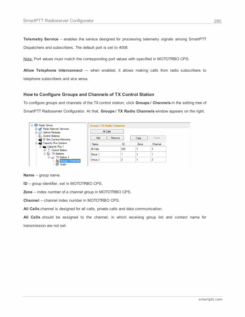
280
smartptt.com
SmartPTT Radioserver Configurator
Telemetry Service – enables the service designed for processing telemetry signals among SmartPTT
Dispatchers and subscribers. The default port is set to 4008.
Note: Port values must match the corresponding port values with specified in MOTOTRBO CPS.
Allow Telephone Interconnect — when enabled, it allows making calls from radio subscribers to
telephone subscribers and vice versa.
How to Configure Groups and Channels of TX Control Station
To configure groups and channels of the TX control station, click Groups / Channels in the setting tree of
SmartPTT Radioserver Configurator. At that, Groups / TX Radio Channels window appears on the right.
Name – group name.
ID – group identifier, set in MOTOTRBO CPS.
Zone – index number of a channel group in MOTOTRBO CPS.
Channel – channel index number in MOTOTRBO CPS.
All Calls channel is designed for all calls, private calls and data communication.
All Calls should be assigned to the channel, in which receiving group list and contact name for
transmission are not set.
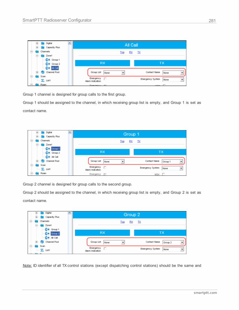
281
smartptt.com
SmartPTT Radioserver Configurator
Group 1 channel is designed for group calls to the first group.
Group 1 should be assigned to the channel, in which receiving group list is empty, and Group 1 is set as
contact name.
Group 2 channel is designed for group calls to the second group.
Group 2 should be assigned to the channel, in which receiving group list is empty, and Group 2 is set as
contact name.
Note: ID identifier of all TX control stations (except dispatching control stations) should be the same and
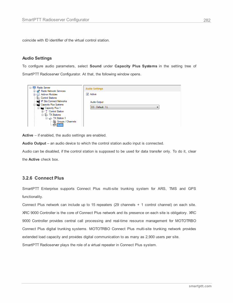
282
smartptt.com
SmartPTT Radioserver Configurator
coincide with ID identifier of the virtual control station.
Audio Settings
To configure audio parameters, select Sound under Capacity Plus Systems in the setting tree of
SmartPTT Radioserver Configurator. At that, the following window opens.
Active – if enabled, the audio settings are enabled.
Audio Output – an audio device to which the control station audio input is connected.
Audio can be disabled, if the control station is supposed to be used for data transfer only. To do it, clear
the Active check box.
3.2.6 Connect Plus
SmartPTT Enterprise supports Connect Plus multi-site trunking system for ARS, TMS and GPS
functionality.
Connect Plus network can include up to 15 repeaters (29 channels + 1 control channel) on each site.
XRC 9000 Controller is the core of Connect Plus network and its presence on each site is obligatory. XRC
9000 Controller provides central call processing and real-time resource management for MOTOTRBO
Connect Plus digital trunking systems. MOTOTRBO Connect Plus multi-site trunking network provides
extended load capacity and provides digital communication to as many as 2,900 users per site.
SmartPTT Radioserver plays the role of a virtual repeater in Connect Plus system.
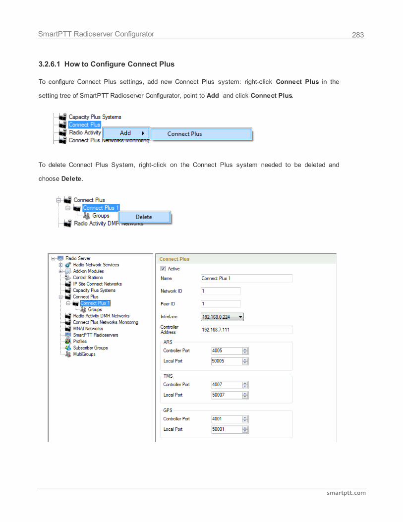
283
smartptt.com
SmartPTT Radioserver Configurator
3.2.6.1 How to Configure Connect Plus
To configure Connect Plus settings, add new Connect Plus system: right-click Connect Plus in the
setting tree of SmartPTT Radioserver Configurator, point to Add and click Connect Plus.
To delete Connect Plus System, right-click on the Connect Plus system needed to be deleted and
choose Delete.
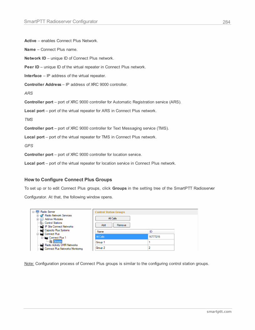
284
smartptt.com
SmartPTT Radioserver Configurator
Active – enables Connect Plus Network.
Name – Connect Plus name.
Network ID – unique ID of Connect Plus network.
Peer ID – unique ID of the virtual repeater in Connect Plus network.
Interface – IP address of the virtual repeater.
Controller Address – IP address of XRC 9000 controller.
ARS
Controller port – port of XRC 9000 controller for Automatic Registration service (ARS).
Local port – port of the virtual repeater for ARS in Connect Plus network.
TMS
Controller port – port of XRC 9000 controller for Text Messaging service (TMS).
Local port – port of the virtual repeater for TMS in Connect Plus network.
GPS
Controller port – port of XRC 9000 controller for location service.
Local port – port of the virtual repeater for location service in Connect Plus network.
How to Configure Connect Plus Groups
To set up or to edit Connect Plus groups, click Groups in the setting tree of the SmartPTT Radioserver
Configurator. At that, the following window opens.
Note: Configuration process of Connect Plus groups is similar to the configuring control station groups.
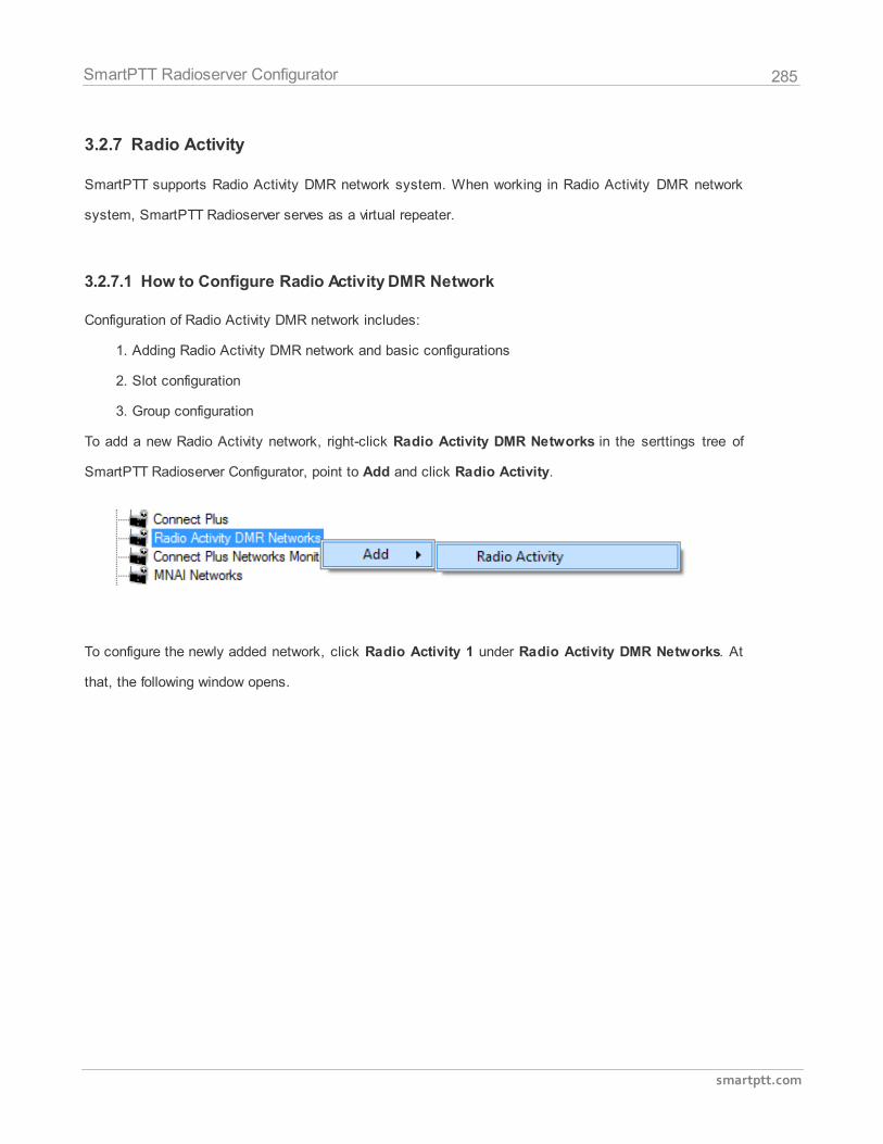
285
smartptt.com
SmartPTT Radioserver Configurator
3.2.7 Radio Activity
SmartPTT supports Radio Activity DMR network system. When working in Radio Activity DMR network
system, SmartPTT Radioserver serves as a virtual repeater.
3.2.7.1 How to Configure Radio Activity DMR Network
Configuration of Radio Activity DMR network includes:
1. Adding Radio Activity DMR network and basic configurations
2. Slot configuration
3. Group configuration
To add a new Radio Activity network, right-click Radio Activity DMR Networks in the serttings tree of
SmartPTT Radioserver Configurator, point to Add and click Radio Activity.
To configure the newly added network, click Radio Activity 1 under Radio Activity DMR Networks. At
that, the following window opens.
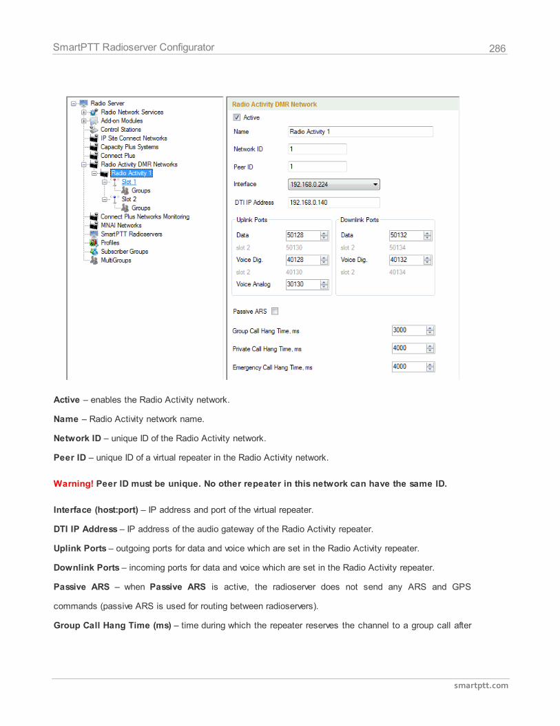
286
smartptt.com
SmartPTT Radioserver Configurator
Active – enables the Radio Activity network.
Name – Radio Activity network name.
Network ID – unique ID of the Radio Activity network.
Peer ID – unique ID of a virtual repeater in the Radio Activity network.
Warning! Peer ID must be unique. No other repeater in this network can have the same ID.
Interface (host:port) – IP address and port of the virtual repeater.
DTI IP Address – IP address of the audio gateway of the Radio Activity repeater.
Uplink Ports – outgoing ports for data and voice which are set in the Radio Activity repeater.
Downlink Ports – incoming ports for data and voice which are set in the Radio Activity repeater.
Passive ARS – when Passive ARS is active, the radioserver does not send any ARS and GPS
commands (passive ARS is used for routing between radioservers).
Group Call Hang Time (ms) – time during which the repeater reserves the channel to a group call after
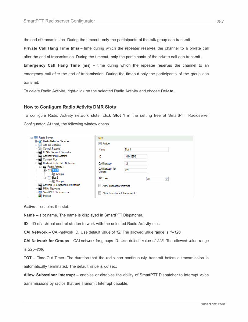
287
smartptt.com
SmartPTT Radioserver Configurator
the end of transmission. During the timeout, only the participants of the talk group can transmit.
Private Call Hang Time (ms) – time during which the repeater reserves the channel to a private call
after the end of transmission. During the timeout, only the participants of the private call can transmit.
Emergency Call Hang Time (ms) – time during which the repeater reserves the channel to an
emergency call after the end of transmission. During the timeout only the participants of the group can
transmit.
To delete Radio Activity, right-click on the selected Radio Activity and choose Delete.
How to Configure Radio Activity DMR Slots
To configure Radio Activity network slots, click Slot 1 in the setting tree of SmartPTT Radioserver
Configurator. At that, the following window opens.
Active – enables the slot.
Name – slot name. The name is displayed in SmartPTT Dispatcher.
ID – ID of a virtual control station to work with the selected Radio Activity slot.
CAI Network – CAI-network ID. Use default value of 12. The allowed value range is 1–126.
CAI Network for Groups – CAI-network for groups ID. Use default value of 225. The allowed value range
is 225–239.
TOT – Time-Out Timer. The duration that the radio can continuously transmit before a transmission is
automatically terminated. The default value is 60 sec.
Allow Subscriber Interrupt – enables or disables the ability of SmartPTT Dispatcher to interrupt voice
transmissions by radios that are Transmit Interrupt capable.
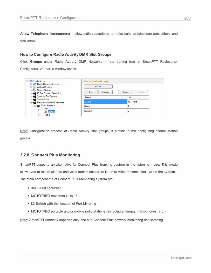
288
smartptt.com
SmartPTT Radioserver Configurator
Allow Telephone Interconnect – allow radio subscribers to make calls to telephone subscribers and
vice versa.
How to Configure Radio Activity DMR Slot Groups
Click Groups under Radio Activity DMR Networks in the setting tree of SmartPTT Radioserver
Configurator. At that, a window opens.
Note: Configuration process of Radio Activity slot groups is similar to the configuring control station
groups.
3.2.8 Connect Plus Monitoring
SmartPTT supports an alternative for Connect Plus trunking system in the listening mode. This mode
allows you to record all data and voice transmissions, to listen to voice transmissions within the system.
The main components of Connect Plus Monitoring system are:
XRC 9000 controller
MOTOTRBO repeaters (1 to 15)
L2 Switch with the function of Port Mirroring
MOTOTRBO portable and/or mobile radio stations (including antennas, microphones, etc.)
Note: SmartPTT currently supports only one-site Connect Plus network monitoring and listening.
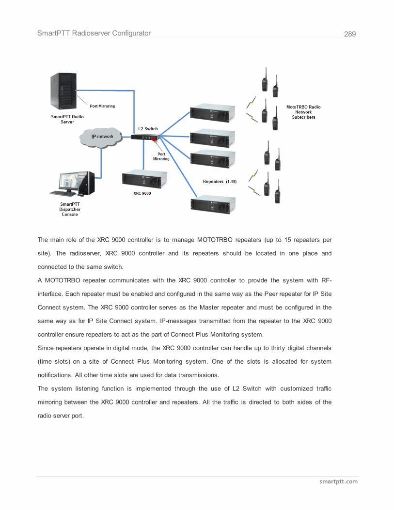
289
smartptt.com
SmartPTT Radioserver Configurator
The main role of the XRC 9000 controller is to manage MOTOTRBO repeaters (up to 15 repeaters per
site). The radioserver, XRC 9000 controller and its repeaters should be located in one place and
connected to the same switch.
A MOTOTRBO repeater communicates with the XRC 9000 controller to provide the system with RF-
interface. Each repeater must be enabled and configured in the same way as the Peer repeater for IP Site
Connect system. The XRC 9000 controller serves as the Master repeater and must be configured in the
same way as for IP Site Connect system. IP-messages transmitted from the repeater to the XRC 9000
controller ensure repeaters to act as the part of Connect Plus Monitoring system.
Since repeaters operate in digital mode, the XRC 9000 controller can handle up to thirty digital channels
(time slots) on a site of Connect Plus Monitoring system. One of the slots is allocated for system
notifications. All other time slots are used for data transmissions.
The system listening function is implemented through the use of L2 Switch with customized traffic
mirroring between the XRC 9000 controller and repeaters. All the traffic is directed to both sides of the
radio server port.
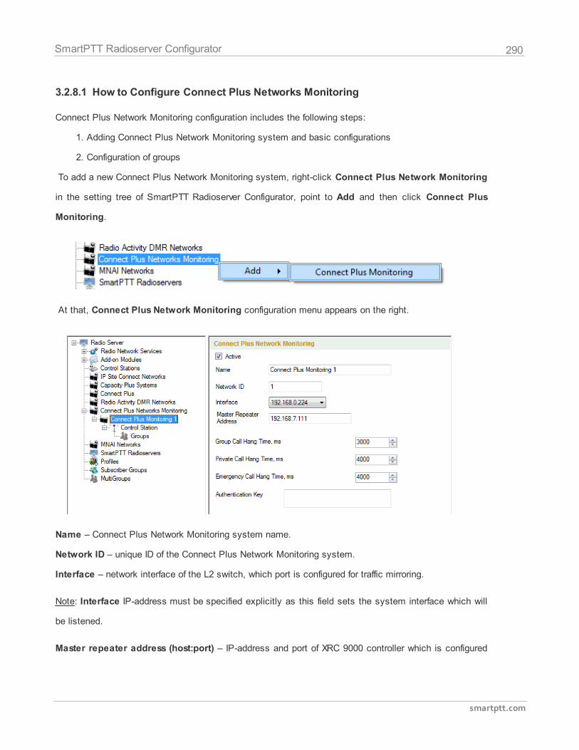
290
smartptt.com
SmartPTT Radioserver Configurator
3.2.8.1 How to Configure Connect Plus Networks Monitoring
Connect Plus Network Monitoring configuration includes the following steps:
1. Adding Connect Plus Network Monitoring system and basic configurations
2. Configuration of groups
To add a new Connect Plus Network Monitoring system, right-click Connect Plus Network Monitoring
in the setting tree of SmartPTT Radioserver Configurator, point to Add and then click Connect Plus
Monitoring.
At that, Connect Plus Network Monitoring configuration menu appears on the right.
Name – Connect Plus Network Monitoring system name.
Network ID – unique ID of the Connect Plus Network Monitoring system.
Interface – network interface of the L2 switch, which port is configured for traffic mirroring.
Note: Interface IP-address must be specified explicitly as this field sets the system interface which will
be listened.
Master repeater address (host:port) – IP-address and port of XRC 9000 controller which is configured
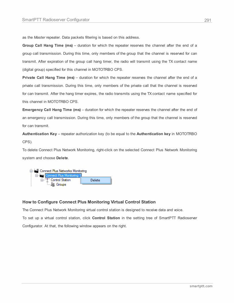
291
smartptt.com
SmartPTT Radioserver Configurator
as the Master repeater. Data packets filtering is based on this address.
Group Call Hang Time (ms) – duration for which the repeater reserves the channel after the end of a
group call transmission. During this time, only members of the group that the channel is reserved for can
transmit. After expiration of the group call hang timer, the radio will transmit using the TX contact name
(digital group) specified for this channel in MOTOTRBO CPS.
Private Call Hang Time (ms) – duration for which the repeater reserves the channel after the end of a
private call transmission. During this time, only members of the private call that the channel is reserved
for can transmit. After the hang timer expires, the radio transmits using the TX contact name specified for
this channel in MOTOTRBO CPS.
Emergency Call Hang Time (ms) – duration for which the repeater reserves the channel after the end of
an emergency call transmission. During this time, only members of the group that the channel is reserved
for can transmit.
Authentication Key – repeater authorization key (to be equal to the Authentication key in MOTOTRBO
CPS).
To delete Connect Plus Network Monitoring, right-click on the selected Connect Plus Network Monitoring
system and choose Delete.
How to Configure Connect Plus Monitoring Virtual Control Station
The Connect Plus Network Monitoring virtual control station is designed to receive data and voice.
To set up a virtual control station, click Control Station in the setting tree of SmartPTT Radioserver
Configurator. At that, the following window appears on the right.
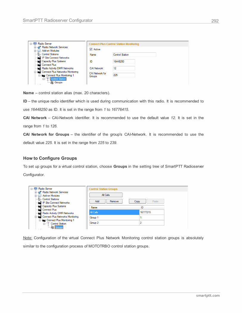
292
smartptt.com
SmartPTT Radioserver Configurator
Name – control station alias (max. 20 characters).
ID – the unique radio identifier which is used during communication with this radio. It is recommended to
use 16448250 as ID. It is set in the range from 1 to 16776415.
CAI Network – CAI-Network identifier. It is recommended to use the default value 12. It is set in the
range from 1 to 126.
CAI Network for Groups – the identifier of the group's CAI-Network. It is recommended to use the
default value 225. It is set in the range from 225 to 239.
How to Configure Groups
To set up groups for a virtual control station, choose Groups in the setting tree of SmartPTT Radioserver
Configurator.
Note: Configuration of the virtual Connect Plus Network Monitoring control station groups is absolutely
similar to the configuration process of MOTOTRBO control station groups.
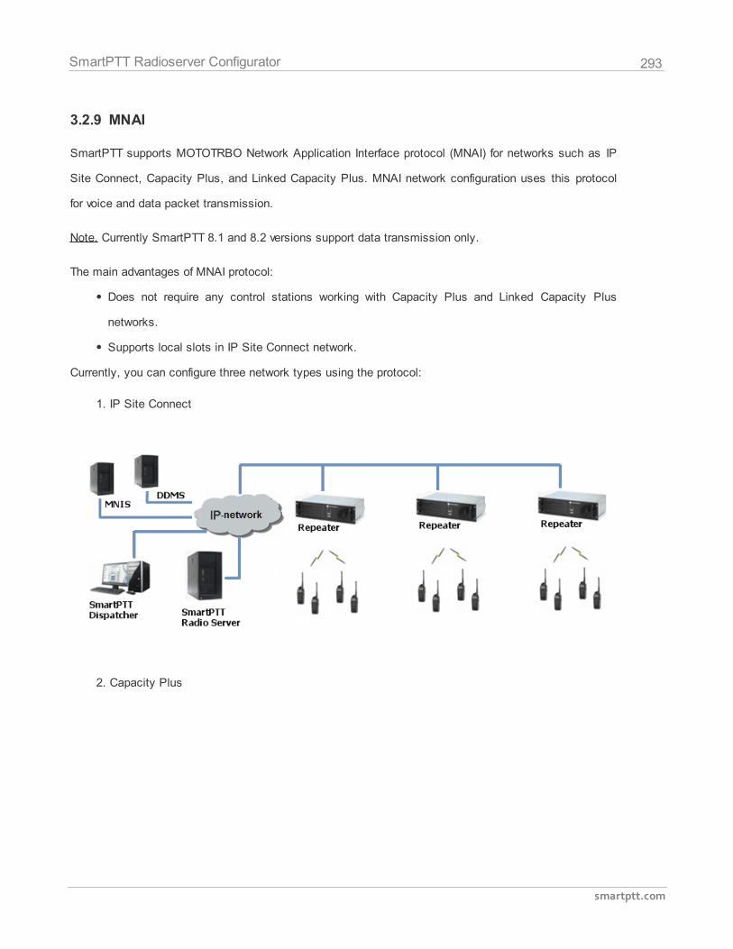
293
smartptt.com
SmartPTT Radioserver Configurator
3.2.9 MNAI
SmartPTT supports MOTOTRBO Network Application Interface protocol (MNAI) for networks such as IP
Site Connect, Capacity Plus, and Linked Capacity Plus. MNAI network configuration uses this protocol
for voice and data packet transmission.
Note. Currently SmartPTT 8.1 and 8.2 versions support data transmission only.
The main advantages of MNAI protocol:
Does not require any control stations working with Capacity Plus and Linked Capacity Plus
networks.
Supports local slots in IP Site Connect network.
Currently, you can configure three network types using the protocol:
1. IP Site Connect
2. Capacity Plus
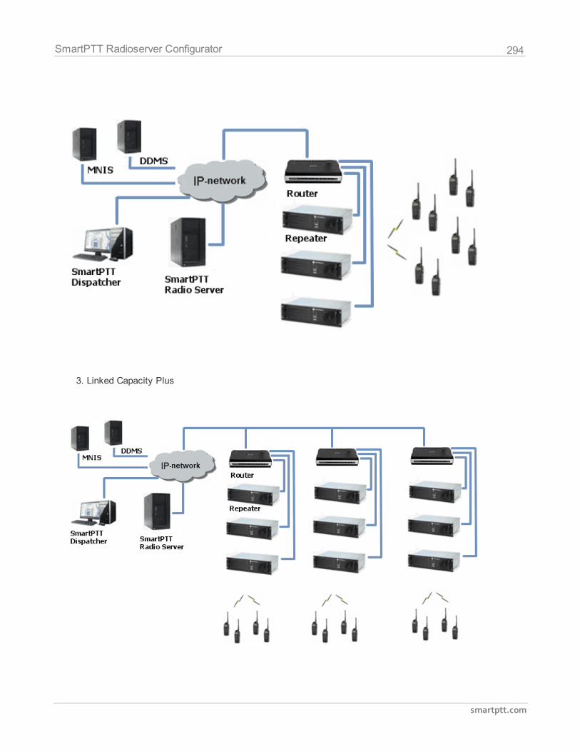
294
smartptt.com
SmartPTT Radioserver Configurator
3. Linked Capacity Plus
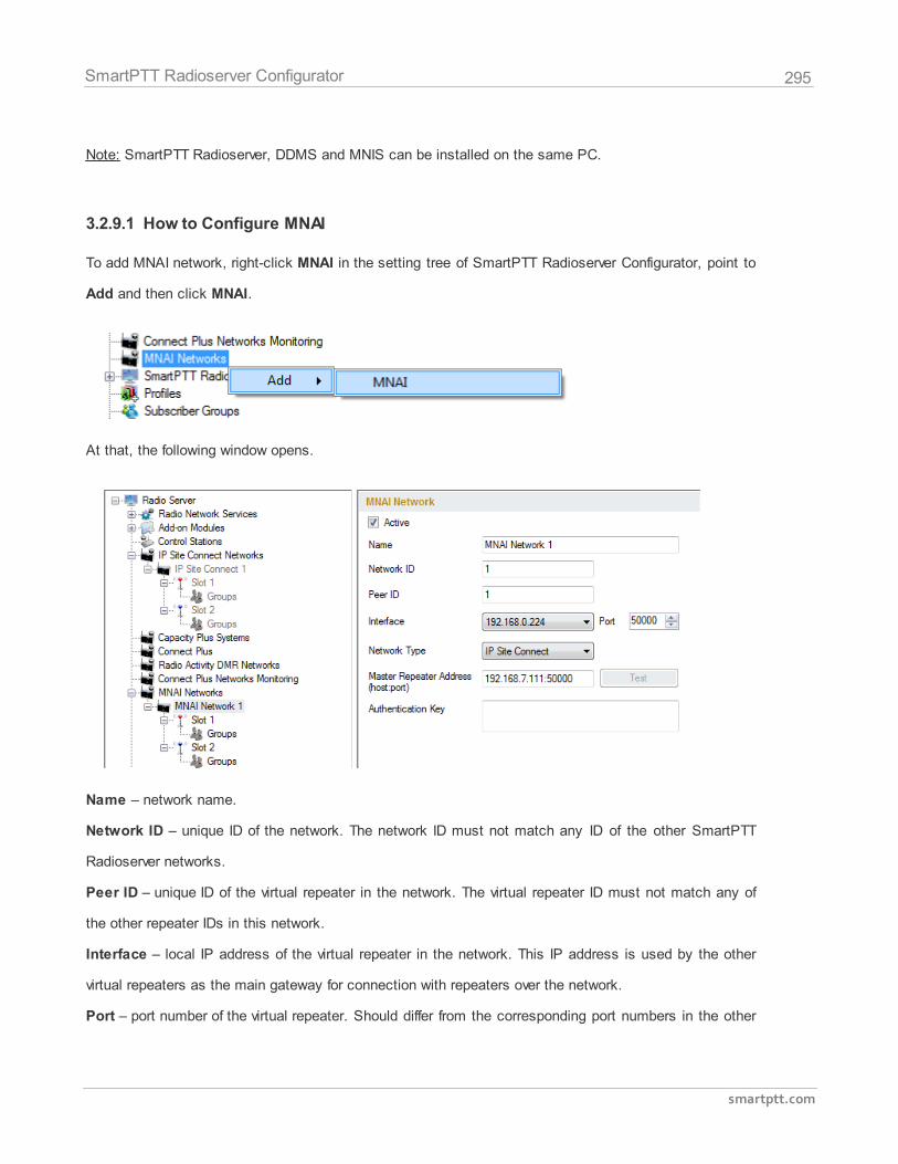
295
smartptt.com
SmartPTT Radioserver Configurator
Note: SmartPTT Radioserver, DDMS and MNIS can be installed on the same PC.
3.2.9.1 How to Configure MNAI
To add MNAI network, right-click MNAI in the setting tree of SmartPTT Radioserver Configurator, point to
Add and then click MNAI.
At that, the following window opens.
Name – network name.
Network ID – unique ID of the network. The network ID must not match any ID of the other SmartPTT
Radioserver networks.
Peer ID – unique ID of the virtual repeater in the network. The virtual repeater ID must not match any of
the other repeater IDs in this network.
Interface – local IP address of the virtual repeater in the network. This IP address is used by the other
virtual repeaters as the main gateway for connection with repeaters over the network.
Port – port number of the virtual repeater. Should differ from the corresponding port numbers in the other
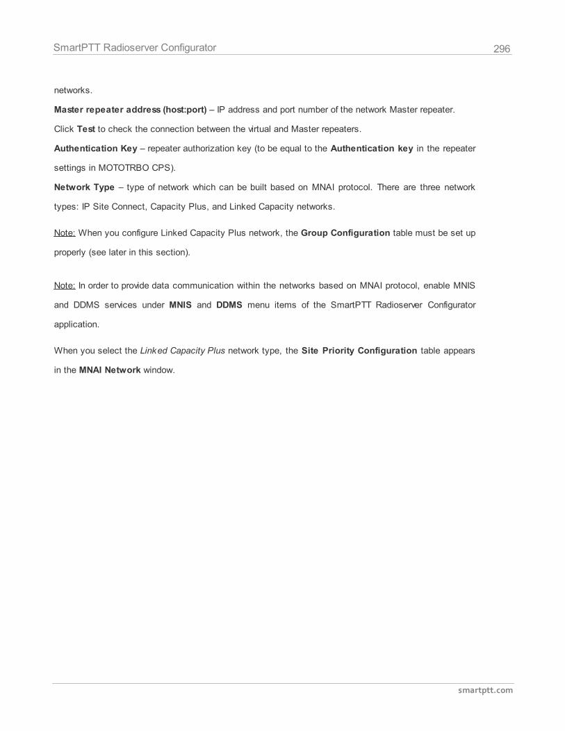
296
smartptt.com
SmartPTT Radioserver Configurator
networks.
Master repeater address (host:port) – IP address and port number of the network Master repeater.
Click Test to check the connection between the virtual and Master repeaters.
Authentication Key – repeater authorization key (to be equal to the Authentication key in the repeater
settings in MOTOTRBO CPS).
Network Type – type of network which can be built based on MNAI protocol. There are three network
types: IP Site Connect, Capacity Plus, and Linked Capacity networks.
Note: When you configure Linked Capacity Plus network, the Group Configuration table must be set up
properly (see later in this section).
Note: In order to provide data communication within the networks based on MNAI protocol, enable MNIS
and DDMS services under MNIS and DDMS menu items of the SmartPTT Radioserver Configurator
application.
When you select the Linked Capacity Plus network type, the Site Priority Configuration table appears
in the MNAI Network window.
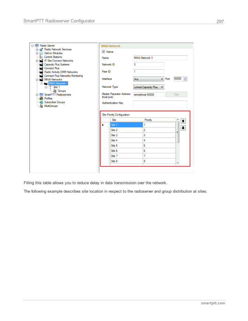
297
smartptt.com
SmartPTT Radioserver Configurator
Filling this table allows you to reduce delay in data transmission over the network.
The following example describes site location in respect to the radioserver and group distribution at sites.
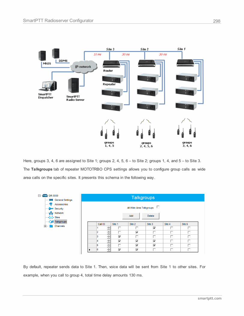
298
smartptt.com
SmartPTT Radioserver Configurator
Here, groups 3, 4, 6 are assigned to Site 1; groups 2, 4, 5, 6 – to Site 2; groups 1, 4, and 5 – to Site 3.
The Talkgroups tab of repeater MOTOTRBO CPS settings allows you to configure group calls as wide
area calls on the specific sites. It presents this schema in the following way.
By default, repeater sends data to Site 1. Then, voice data will be sent from Site 1 to other sites. For
example, when you call to group 4, total time delay amounts 130 ms.
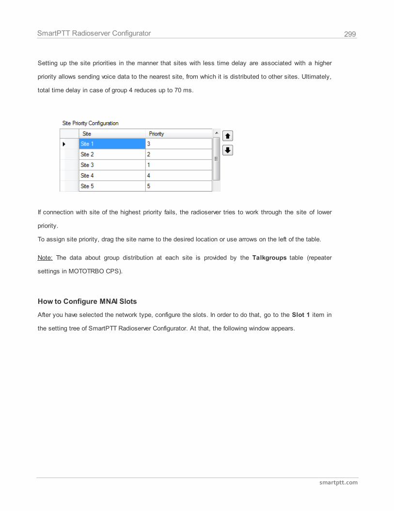
299
smartptt.com
SmartPTT Radioserver Configurator
Setting up the site priorities in the manner that sites with less time delay are associated with a higher
priority allows sending voice data to the nearest site, from which it is distributed to other sites. Ultimately,
total time delay in case of group 4 reduces up to 70 ms.
If connection with site of the highest priority fails, the radioserver tries to work through the site of lower
priority.
To assign site priority, drag the site name to the desired location or use arrows on the left of the table.
Note: The data about group distribution at each site is provided by the Talkgroups table (repeater
settings in MOTOTRBO CPS).
How to Configure MNAI Slots
After you have selected the network type, configure the slots. In order to do that, go to the Slot 1 item in
the setting tree of SmartPTT Radioserver Configurator. At that, the following window appears.
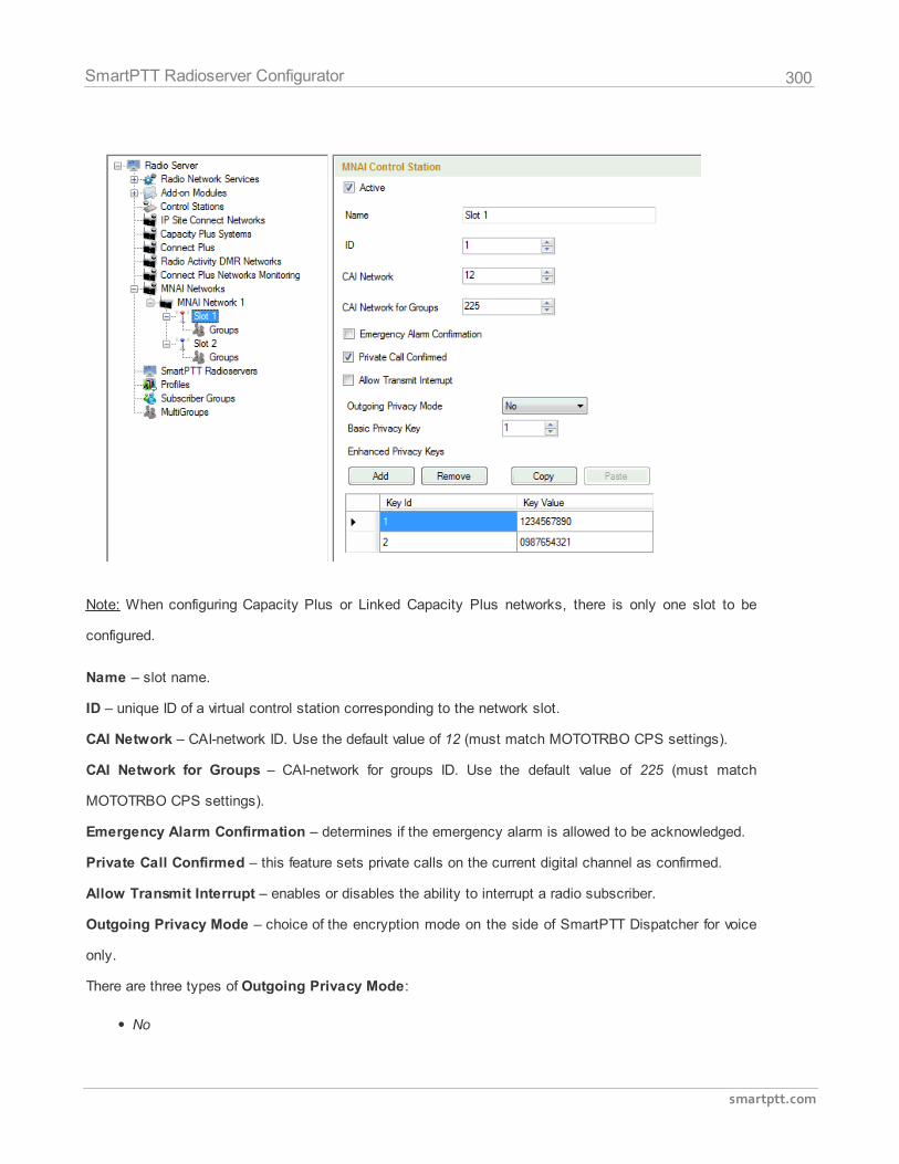
300
smartptt.com
SmartPTT Radioserver Configurator
Note: When configuring Capacity Plus or Linked Capacity Plus networks, there is only one slot to be
configured.
Name – slot name.
ID – unique ID of a virtual control station corresponding to the network slot.
CAI Network – CAI-network ID. Use the default value of 12 (must match MOTOTRBO CPS settings).
CAI Network for Groups – CAI-network for groups ID. Use the default value of 225 (must match
MOTOTRBO CPS settings).
Emergency Alarm Confirmation – determines if the emergency alarm is allowed to be acknowledged.
Private Call Confirmed – this feature sets private calls on the current digital channel as confirmed.
Allow Transmit Interrupt – enables or disables the ability to interrupt a radio subscriber.
Outgoing Privacy Mode – choice of the encryption mode on the side of SmartPTT Dispatcher for voice
only.
There are three types of Outgoing Privacy Mode:
No
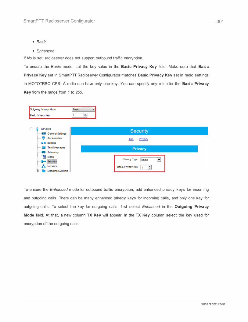
301
smartptt.com
SmartPTT Radioserver Configurator
Basic
Enhanced
If No is set, radioserver does not support outbound traffic encryption.
To ensure the Basic mode, set the key value in the Basic Privacy Key field. Make sure that Basic
Privacy Key set in SmartPTT Radioserver Configurator matches Basic Privacy Key set in radio settings
in MOTOTRBO CPS. A radio can have only one key. You can specify any value for the Basic Privacy
Key from the range from 1 to 255.
To ensure the Enhanced mode for outbound traffic encryption, add enhanced privacy keys for incoming
and outgoing calls. There can be many enhanced privacy keys for incoming calls, and only one key for
outgoing calls. To select the key for outgoing calls, first select Enhanced in the Outgoing Privacy
Mode field. At that, a new column TX Key will appear. In the TX Key column select the key used for
encryption of the outgoing calls.
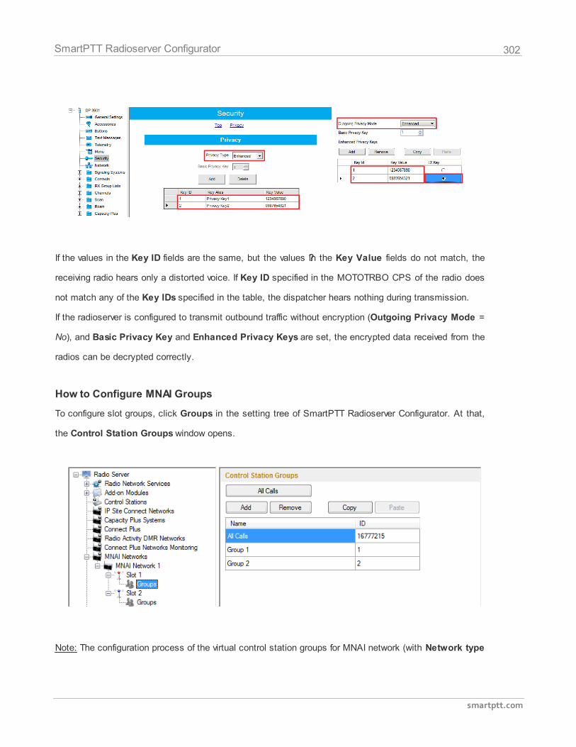
302
smartptt.com
SmartPTT Radioserver Configurator
If the values in the Key ID fields are the same, but the values ??in the Key Value fields do not match, the
receiving radio hears only a distorted voice. If Key ID specified in the MOTOTRBO CPS of the radio does
not match any of the Key IDs specified in the table, the dispatcher hears nothing during transmission.
If the radioserver is configured to transmit outbound traffic without encryption (Outgoing Privacy Mode =
No), and Basic Privacy Key and Enhanced Privacy Keys are set, the encrypted data received from the
radios can be decrypted correctly.
How to Configure MNAI Groups
To configure slot groups, click Groups in the setting tree of SmartPTT Radioserver Configurator. At that,
the Control Station Groups window opens.
Note: The configuration process of the virtual control station groups for MNAI network (with Network type
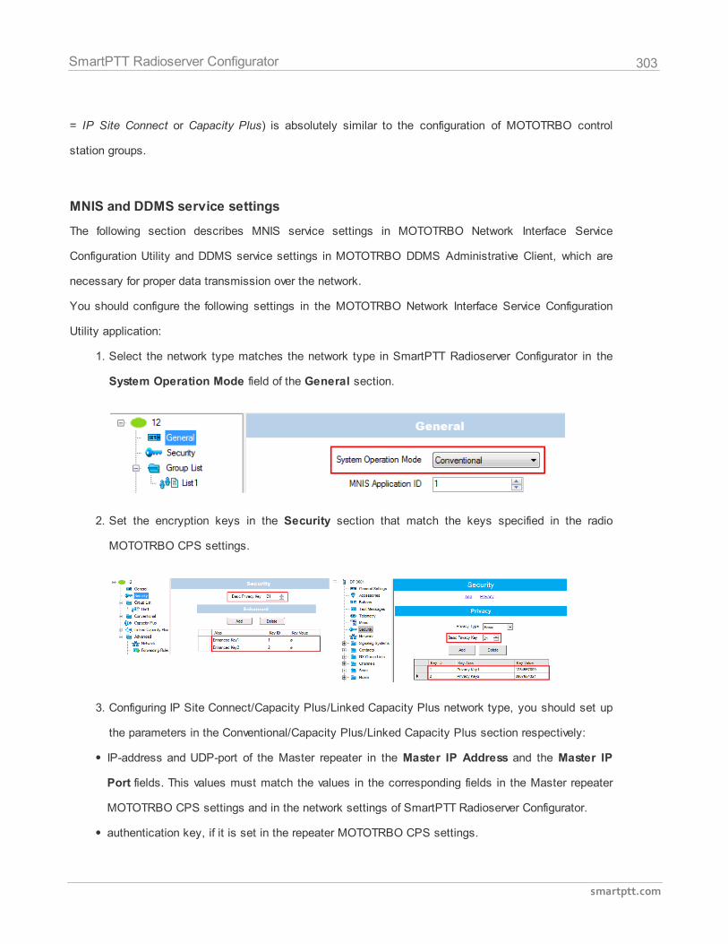
303
smartptt.com
SmartPTT Radioserver Configurator
= IP Site Connect or Capacity Plus) is absolutely similar to the configuration of MOTOTRBO control
station groups.
MNIS and DDMS service settings
The following section describes MNIS service settings in MOTOTRBO Network Interface Service
Configuration Utility and DDMS service settings in MOTOTRBO DDMS Administrative Client, which are
necessary for proper data transmission over the network.
You should configure the following settings in the MOTOTRBO Network Interface Service Configuration
Utility application:
1. Select the network type matches the network type in SmartPTT Radioserver Configurator in the
System Operation Mode field of the General section.
2. Set the encryption keys in the Security section that match the keys specified in the radio
MOTOTRBO CPS settings.
3. Configuring IP Site Connect/Capacity Plus/Linked Capacity Plus network type, you should set up
the parameters in the Conventional/Capacity Plus/Linked Capacity Plus section respectively:
IP-address and UDP-port of the Master repeater in the Master IP Address and the Master IP
Port fields. This values must match the values in the corresponding fields in the Master repeater
MOTOTRBO CPS settings and in the network settings of SmartPTT Radioserver Configurator.
authentication key, if it is set in the repeater MOTOTRBO CPS settings.
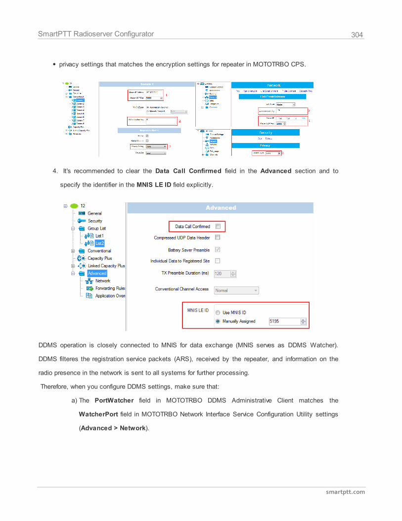
304
smartptt.com
SmartPTT Radioserver Configurator
privacy settings that matches the encryption settings for repeater in MOTOTRBO CPS.
4. It's recommended to clear the Data Call Confirmed field in the Advanced section and to
specify the identifier in the MNIS LE ID field explicitly.
DDMS operation is closely connected to MNIS for data exchange (MNIS serves as DDMS Watcher).
DDMS filteres the registration service packets (ARS), received by the repeater, and information on the
radio presence in the network is sent to all systems for further processing.
Therefore, when you configure DDMS settings, make sure that:
a) The PortWatcher field in MOTOTRBO DDMS Administrative Client matches the
WatcherPort field in MOTOTRBO Network Interface Service Configuration Utility settings
(Advanced > Network).
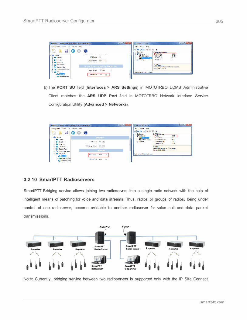
305
smartptt.com
SmartPTT Radioserver Configurator
b) The PORT SU field (Interfaces > ARS Settings) in MOTOTRBO DDMS Administrative
Client matches the ARS UDP Port field in MOTOTRBO Network Interface Service
Configuration Utility (Advanced > Networks).
3.2.10 SmartPTT Radioservers
SmartPTT Bridging service allows joining two radioservers into a single radio network with the help of
intelligent means of patching for voice and data streams. Thus, radios or groups of radios, being under
control of one radioserver, become available to another radioserver for voice call and data packet
transmissions.
Note: Currently, bridging service between two radioservers is supported only with the IP Site Connect
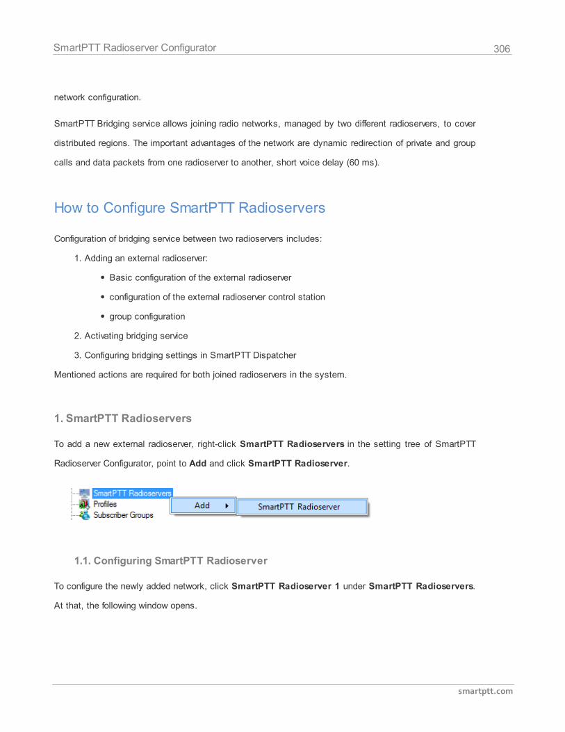
306
smartptt.com
SmartPTT Radioserver Configurator
network configuration.
SmartPTT Bridging service allows joining radio networks, managed by two different radioservers, to cover
distributed regions. The important advantages of the network are dynamic redirection of private and group
calls and data packets from one radioserver to another, short voice delay (60 ms).
How to Configure SmartPTT Radioservers
Configuration of bridging service between two radioservers includes:
1. Adding an external radioserver:
Basic configuration of the external radioserver
configuration of the external radioserver control station
group configuration
2. Activating bridging service
3. Configuring bridging settings in SmartPTT Dispatcher
Mentioned actions are required for both joined radioservers in the system.
1. SmartPTT Radioservers
To add a new external radioserver, right-click SmartPTT Radioservers in the setting tree of SmartPTT
Radioserver Configurator, point to Add and click SmartPTT Radioserver.
1.1. Configuring SmartPTT Radioserver
To configure the newly added network, click SmartPTT Radioserver 1 under SmartPTT Radioservers.
At that, the following window opens.
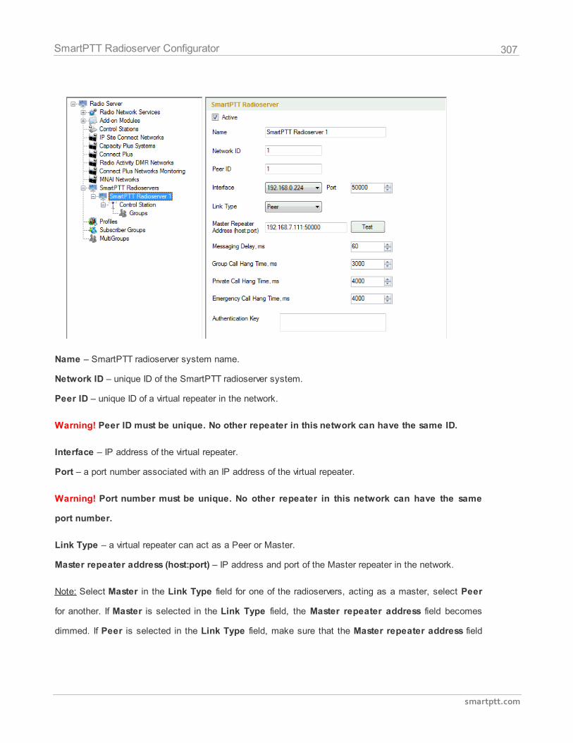
307
smartptt.com
SmartPTT Radioserver Configurator
Name – SmartPTT radioserver system name.
Network ID – unique ID of the SmartPTT radioserver system.
Peer ID – unique ID of a virtual repeater in the network.
Warning! Peer ID must be unique. No other repeater in this network can have the same ID.
Interface – IP address of the virtual repeater.
Port – a port number associated with an IP address of the virtual repeater.
Warning! Port number must be unique. No other repeater in this network can have the same
port number.
Link Type – a virtual repeater can act as a Peer or Master.
Master repeater address (host:port) – IP address and port of the Master repeater in the network.
Note: Select Master in the Link Type field for one of the radioservers, acting as a master, select Peer
for another. If Master is selected in the Link Type field, the Master repeater address field becomes
dimmed. If Peer is selected in the Link Type field, make sure that the Master repeater address field
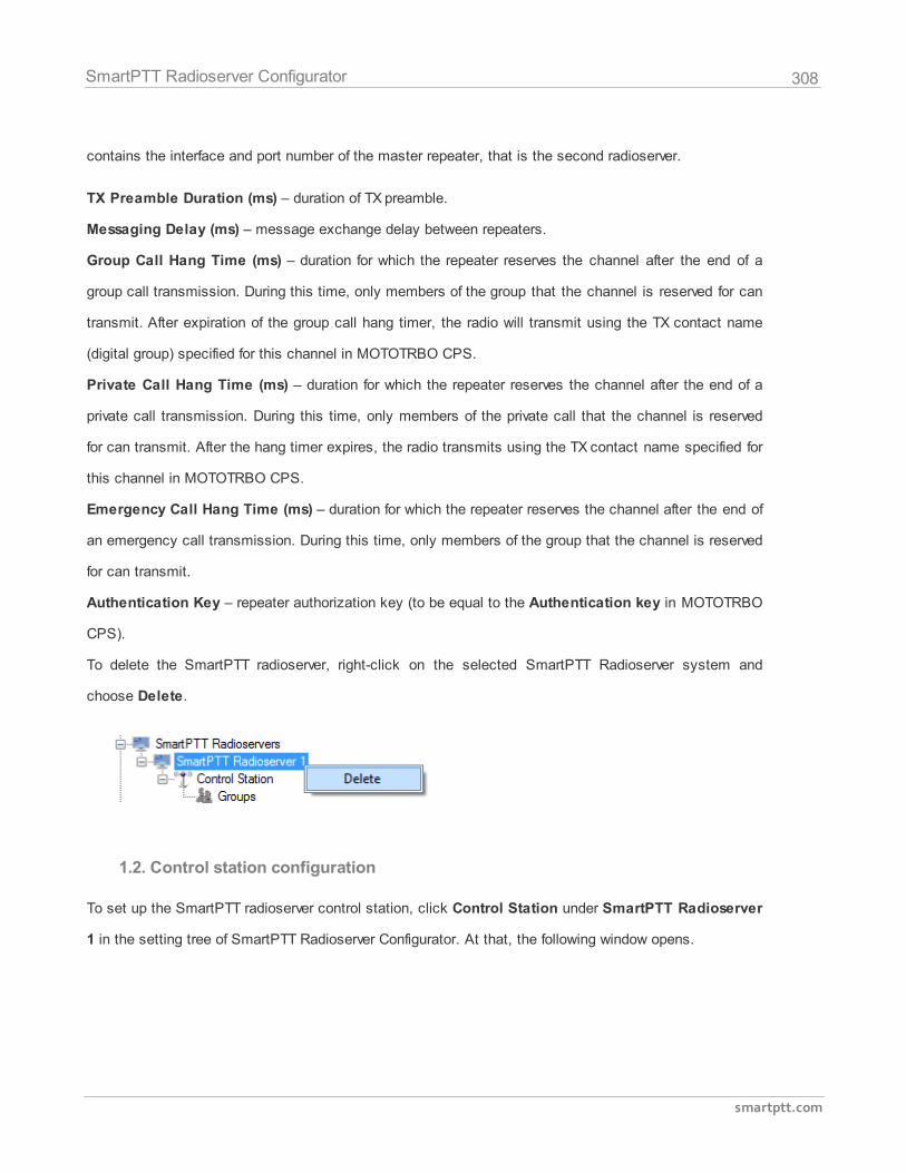
308
smartptt.com
SmartPTT Radioserver Configurator
contains the interface and port number of the master repeater, that is the second radioserver.
TX Preamble Duration (ms) – duration of TX preamble.
Messaging Delay (ms) – message exchange delay between repeaters.
Group Call Hang Time (ms) – duration for which the repeater reserves the channel after the end of a
group call transmission. During this time, only members of the group that the channel is reserved for can
transmit. After expiration of the group call hang timer, the radio will transmit using the TX contact name
(digital group) specified for this channel in MOTOTRBO CPS.
Private Call Hang Time (ms) – duration for which the repeater reserves the channel after the end of a
private call transmission. During this time, only members of the private call that the channel is reserved
for can transmit. After the hang timer expires, the radio transmits using the TX contact name specified for
this channel in MOTOTRBO CPS.
Emergency Call Hang Time (ms) – duration for which the repeater reserves the channel after the end of
an emergency call transmission. During this time, only members of the group that the channel is reserved
for can transmit.
Authentication Key – repeater authorization key (to be equal to the Authentication key in MOTOTRBO
CPS).
To delete the SmartPTT radioserver, right-click on the selected SmartPTT Radioserver system and
choose Delete.
1.2. Control station configuration
To set up the SmartPTT radioserver control station, click Control Station under SmartPTT Radioserver
1 in the setting tree of SmartPTT Radioserver Configurator. At that, the following window opens.
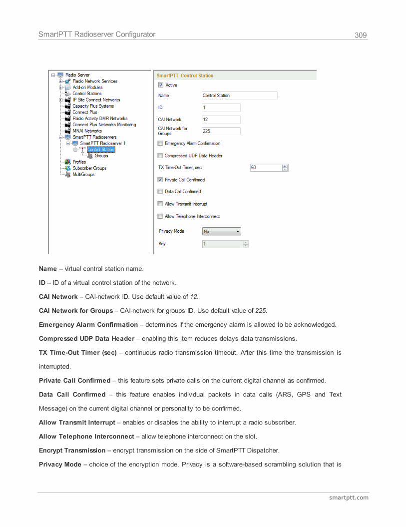
309
smartptt.com
SmartPTT Radioserver Configurator
Name – virtual control station name.
ID – ID of a virtual control station of the network.
CAI Network – CAI-network ID. Use default value of 12.
CAI Network for Groups – CAI-network for groups ID. Use default value of 225.
Emergency Alarm Confirmation – determines if the emergency alarm is allowed to be acknowledged.
Compressed UDP Data Header – enabling this item reduces delays data transmissions.
TX Time-Out Timer (sec) – continuous radio transmission timeout. After this time the transmission is
interrupted.
Private Call Confirmed – this feature sets private calls on the current digital channel as confirmed.
Data Call Confirmed – this feature enables individual packets in data calls (ARS, GPS and Text
Message) on the current digital channel or personality to be confirmed.
Allow Transmit Interrupt – enables or disables the ability to interrupt a radio subscriber.
Allow Telephone Interconnect – allow telephone interconnect on the slot.
Encrypt Transmission – encrypt transmission on the side of SmartPTT Dispatcher.
Privacy Mode – choice of the encryption mode. Privacy is a software-based scrambling solution that is
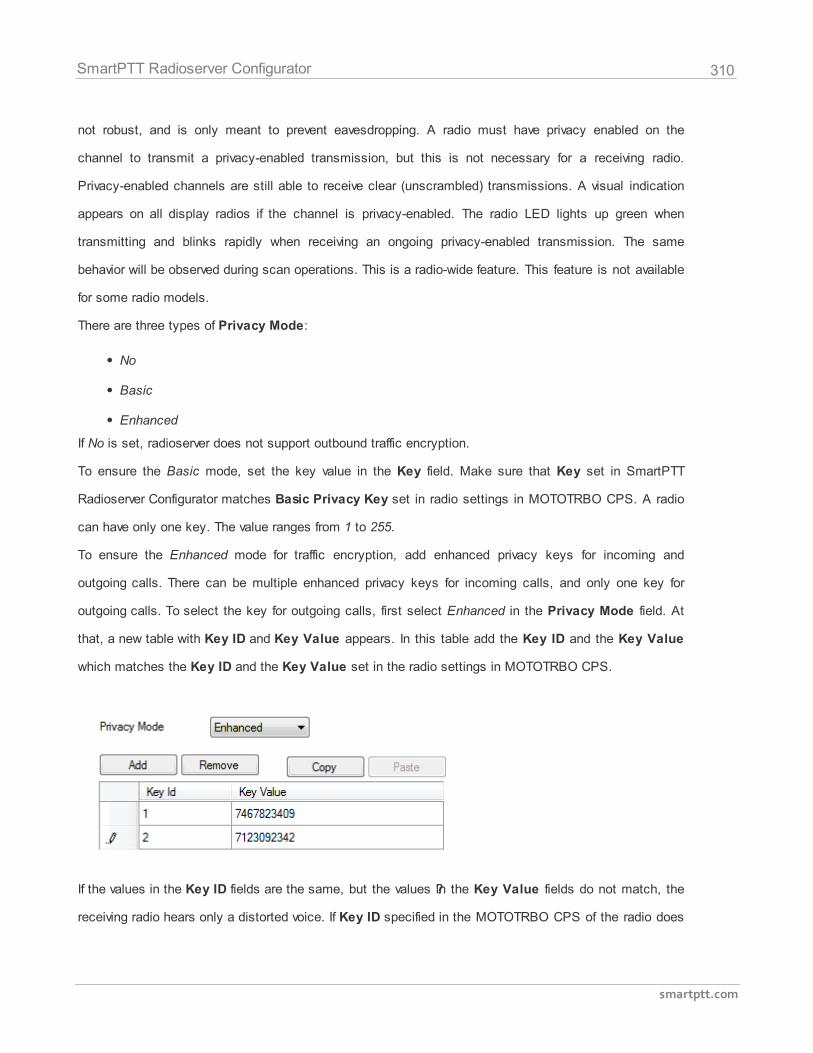
310
smartptt.com
SmartPTT Radioserver Configurator
not robust, and is only meant to prevent eavesdropping. A radio must have privacy enabled on the
channel to transmit a privacy-enabled transmission, but this is not necessary for a receiving radio.
Privacy-enabled channels are still able to receive clear (unscrambled) transmissions. A visual indication
appears on all display radios if the channel is privacy-enabled. The radio LED lights up green when
transmitting and blinks rapidly when receiving an ongoing privacy-enabled transmission. The same
behavior will be observed during scan operations. This is a radio-wide feature. This feature is not available
for some radio models.
There are three types of Privacy Mode:
No
Basic
Enhanced
If No is set, radioserver does not support outbound traffic encryption.
To ensure the Basic mode, set the key value in the Key field. Make sure that Key set in SmartPTT
Radioserver Configurator matches Basic Privacy Key set in radio settings in MOTOTRBO CPS. A radio
can have only one key. The value ranges from 1 to 255.
To ensure the Enhanced mode for traffic encryption, add enhanced privacy keys for incoming and
outgoing calls. There can be multiple enhanced privacy keys for incoming calls, and only one key for
outgoing calls. To select the key for outgoing calls, first select Enhanced in the Privacy Mode field. At
that, a new table with Key ID and Key Value appears. In this table add the Key ID and the Key Value
which matches the Key ID and the Key Value set in the radio settings in MOTOTRBO CPS.
If the values in the Key ID fields are the same, but the values ??in the Key Value fields do not match, the
receiving radio hears only a distorted voice. If Key ID specified in the MOTOTRBO CPS of the radio does
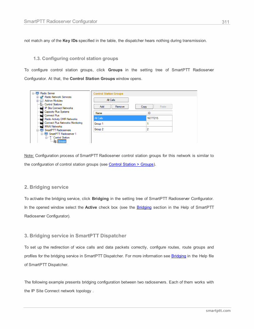
311
smartptt.com
SmartPTT Radioserver Configurator
not match any of the Key IDs specified in the table, the dispatcher hears nothing during transmission.
1.3. Configuring control station groups
To configure control station groups, click Groups in the setting tree of SmartPTT Radioserver
Configurator. At that, the Control Station Groups window opens.
Note: Configuration process of SmartPTT Radioserver control station groups for this network is similar to
the configuration of control station groups (see Control Station > Groups).
2. Bridging service
To activate the bridging service, click Bridging in the setting tree of SmartPTT Radioserver Configurator.
In the opened window select the Active check box (see the Bridging section in the Help of SmartPTT
Radioserver Configurator).
3. Bridging service in SmartPTT Dispatcher
To set up the redirection of voice calls and data packets correctly, configure routes, route groups and
profiles for the bridging service in SmartPTT Dispatcher. For more information see Bridging in the Help file
of SmartPTT Dispatcher.
The following example presents bridging configuration between two radioservers. Each of them works with
the IP Site Connect network topology .
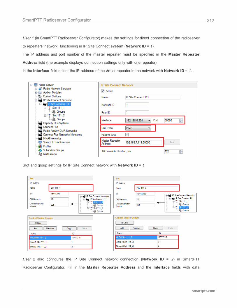
312
smartptt.com
SmartPTT Radioserver Configurator
User 1 (in SmartPTT Radioserver Configurator) makes the settings for direct connection of the radioserver
to repeaters' network, functioning in IP Site Connect system (Network ID = 1).
The IP address and port number of the master repeater must be specified in the Master Repeater
Address field (the example displays connection settings only with one repeater).
In the Interface field select the IP address of the virtual repeater in the network with Network ID = 1.
Slot and group settings for IP Site Connect network with Network ID = 1
User 2 also configures the IP Site Connect network connection (Network ID = 2) in SmartPTT
Radioserver Configurator. Fill in the Master Repeater Address and the Interface fields with data
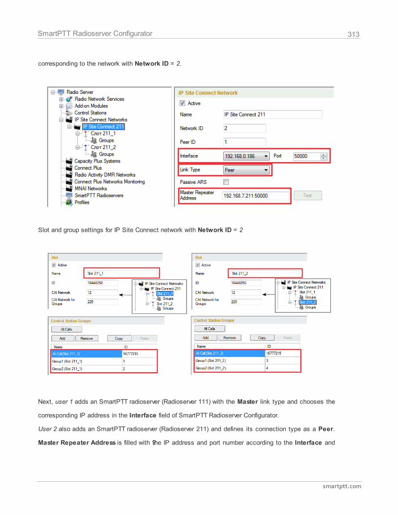
313
smartptt.com
SmartPTT Radioserver Configurator
corresponding to the network with Network ID = 2.
Slot and group settings for IP Site Connect network with Network ID = 2
Next, user 1 adds an SmartPTT radioserver (Radioserver 111) with the Master link type and chooses the
corresponding IP address in the Interface field of SmartPTT Radioserver Configurator.
User 2 also adds an SmartPTT radioserver (Radioserver 211) and defines its connection type as a Peer.
Master Repeater Address is filled with ??the IP address and port number according to the Interface and
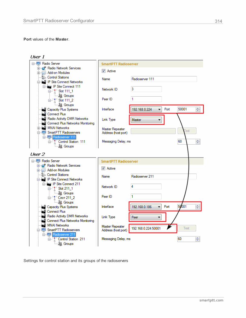
314
smartptt.com
SmartPTT Radioserver Configurator
Port values of the Master.
Settings for control station and its groups of the radioservers
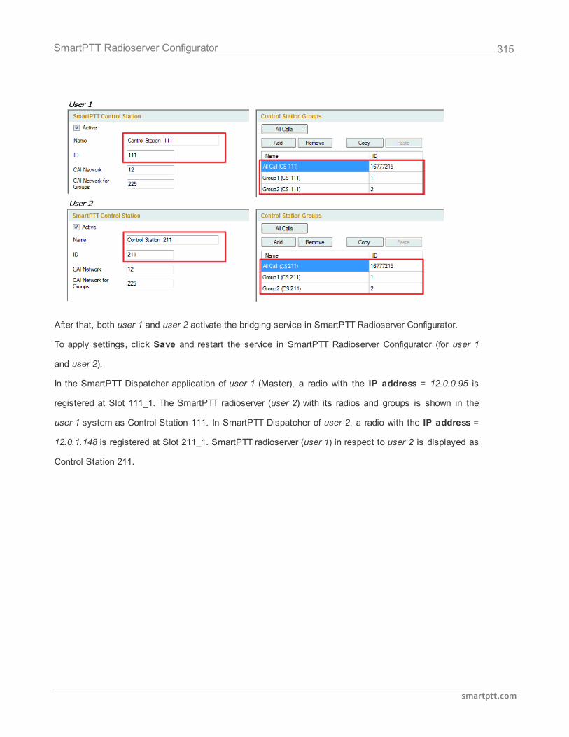
315
smartptt.com
SmartPTT Radioserver Configurator
After that, both user 1 and user 2 activate the bridging service in SmartPTT Radioserver Configurator.
To apply settings, click Save and restart the service in SmartPTT Radioserver Configurator (for user 1
and user 2).
In the SmartPTT Dispatcher application of user 1 (Master), a radio with the IP address = 12.0.0.95 is
registered at Slot 111_1. The SmartPTT radioserver (user 2) with its radios and groups is shown in the
user 1 system as Control Station 111. In SmartPTT Dispatcher of user 2, a radio with the IP address =
12.0.1.148 is registered at Slot 211_1. SmartPTT radioserver (user 1) in respect to user 2 is displayed as
Control Station 211.
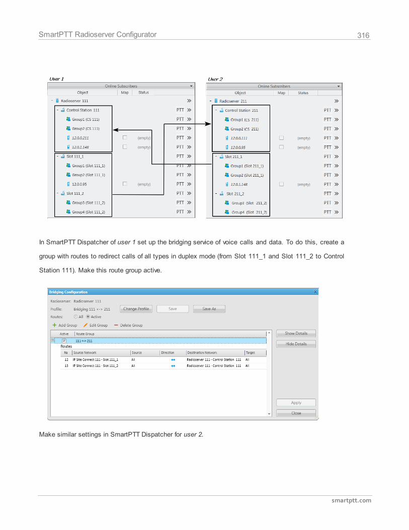
316
smartptt.com
SmartPTT Radioserver Configurator
In SmartPTT Dispatcher of user 1 set up the bridging service of voice calls and data. To do this, create a
group with routes to redirect calls of all types in duplex mode (from Slot 111_1 and Slot 111_2 to Control
Station 111). Make this route group active.
Make similar settings in SmartPTT Dispatcher for user 2.
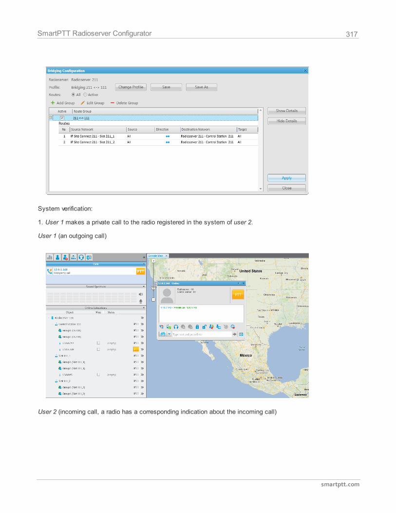
317
smartptt.com
SmartPTT Radioserver Configurator
System verification:
1. User 1 makes a private call to the radio registered in the system of user 2.
User 1 (an outgoing call)
User 2 (incoming call, a radio has a corresponding indication about the incoming call)
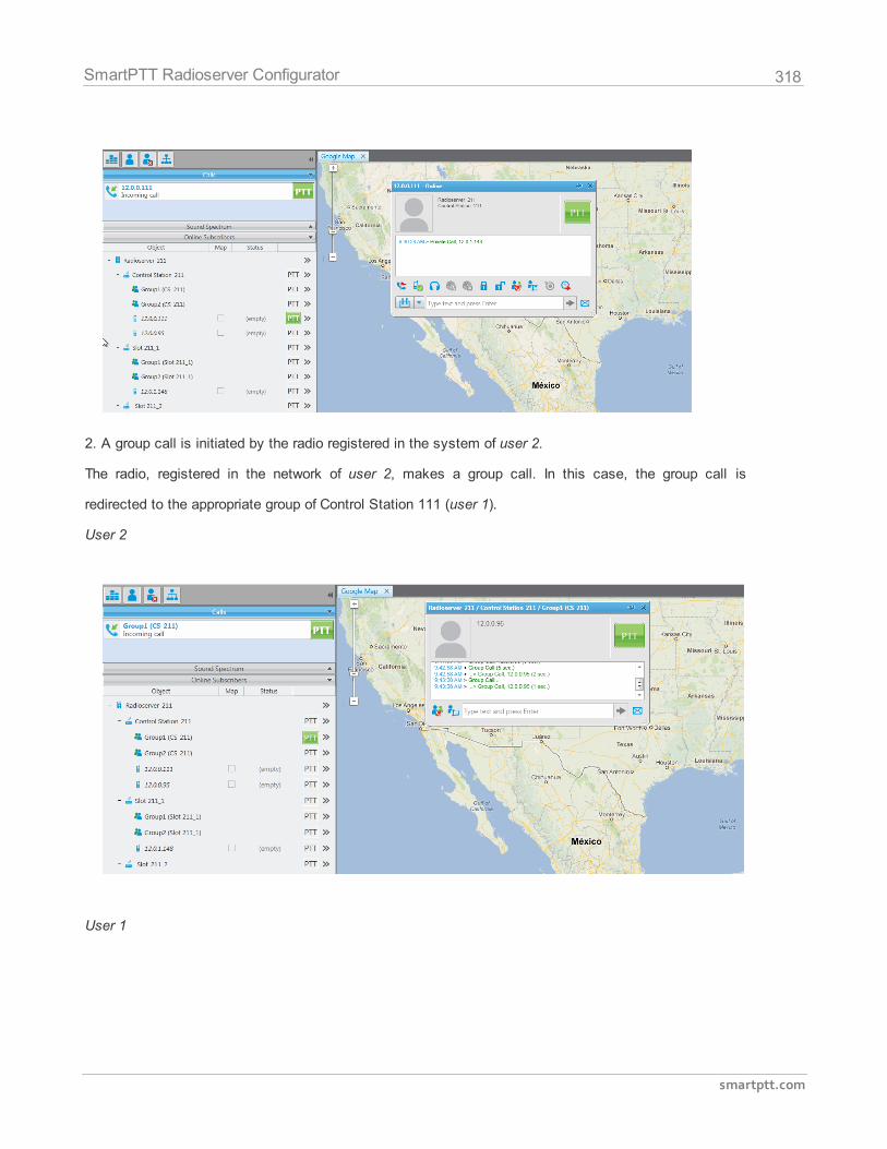
318
smartptt.com
SmartPTT Radioserver Configurator
2. A group call is initiated by the radio registered in the system of user 2.
The radio, registered in the network of user 2, makes a group call. In this case, the group call is
redirected to the appropriate group of Control Station 111 (user 1).
User 2
User 1
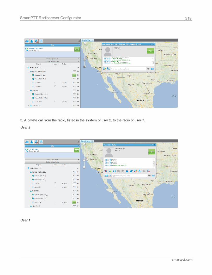
319
smartptt.com
SmartPTT Radioserver Configurator
3. A private call from the radio, listed in the system of user 2, to the radio of user 1.
User 2
User 1
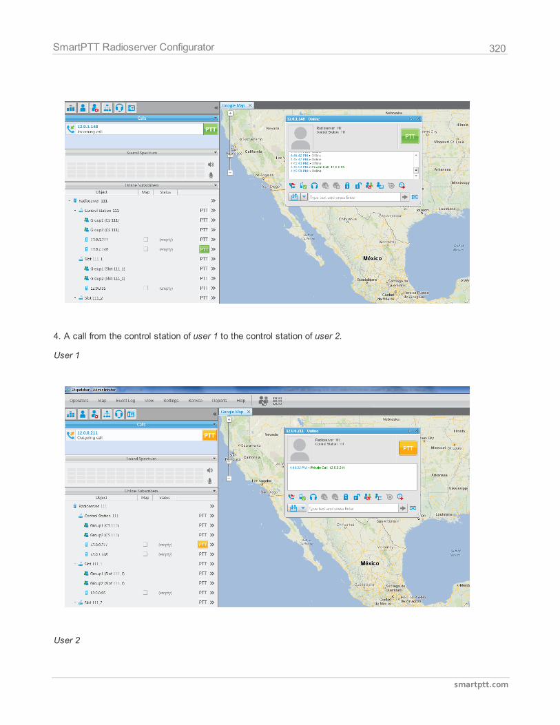
320
smartptt.com
SmartPTT Radioserver Configurator
4. A call from the control station of user 1 to the control station of user 2.
User 1
User 2
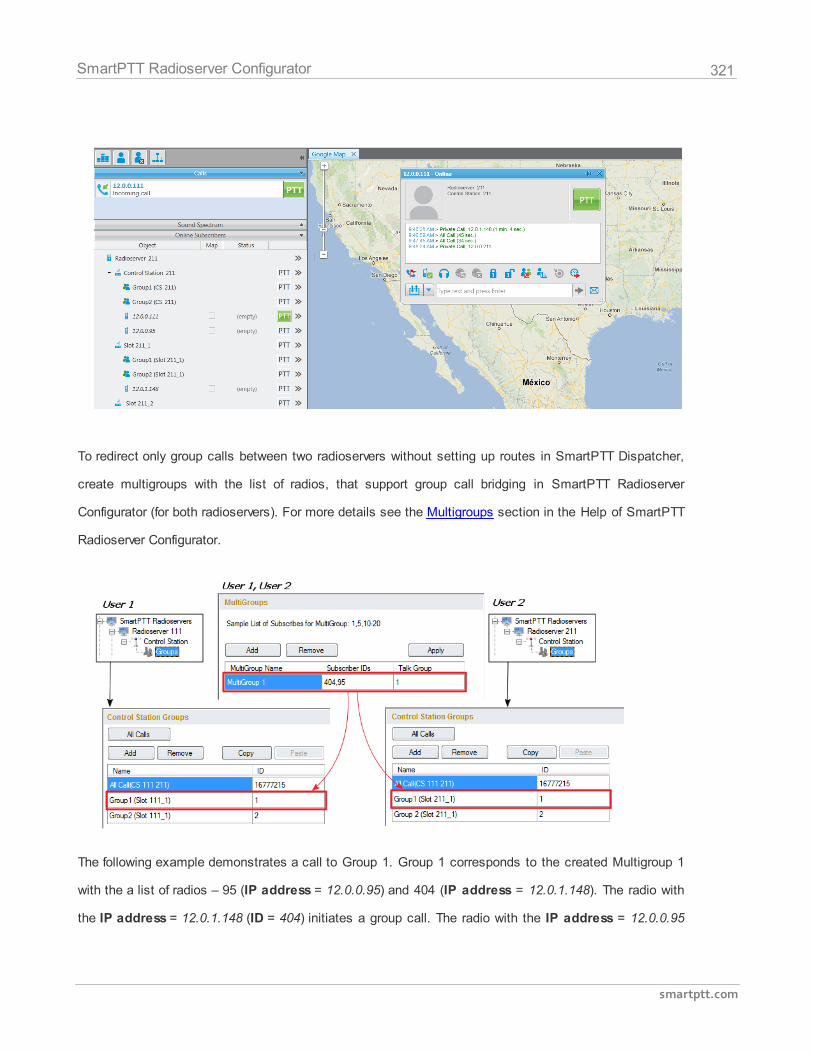
321
smartptt.com
SmartPTT Radioserver Configurator
To redirect only group calls between two radioservers without setting up routes in SmartPTT Dispatcher,
create multigroups with the list of radios, that support group call bridging in SmartPTT Radioserver
Configurator (for both radioservers). For more details see the Multigroups section in the Help of SmartPTT
Radioserver Configurator.
The following example demonstrates a call to Group 1. Group 1 corresponds to the created Multigroup 1
with the a list of radios – 95 (IP address = 12.0.0.95) and 404 (IP address = 12.0.1.148). The radio with
the IP address = 12.0.1.148 (ID = 404) initiates a group call. The radio with the IP address = 12.0.0.95
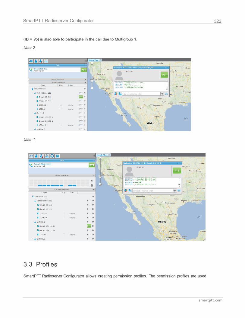
322
smartptt.com
SmartPTT Radioserver Configurator
(ID = 95) is also able to participate in the call due to Multigroup 1.
User 2
User 1
3.3 Profiles
SmartPTT Radioserver Configurator allows creating permission profiles. The permission profiles are used
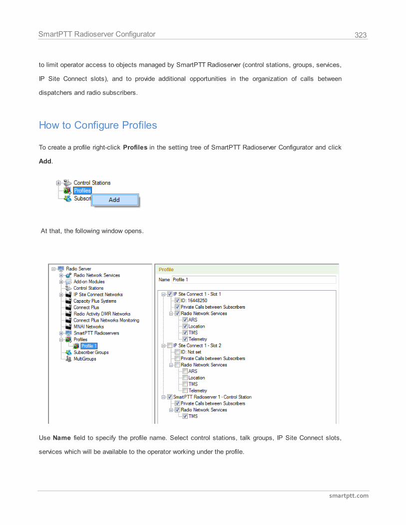
323
smartptt.com
SmartPTT Radioserver Configurator
to limit operator access to objects managed by SmartPTT Radioserver (control stations, groups, services,
IP Site Connect slots), and to provide additional opportunities in the organization of calls between
dispatchers and radio subscribers.
How to Configure Profiles
To create a profile right-click Profiles in the setting tree of SmartPTT Radioserver Configurator and click
Add.
At that, the following window opens.
Use Name field to specify the profile name. Select control stations, talk groups, IP Site Connect slots,
services which will be available to the operator working under the profile.
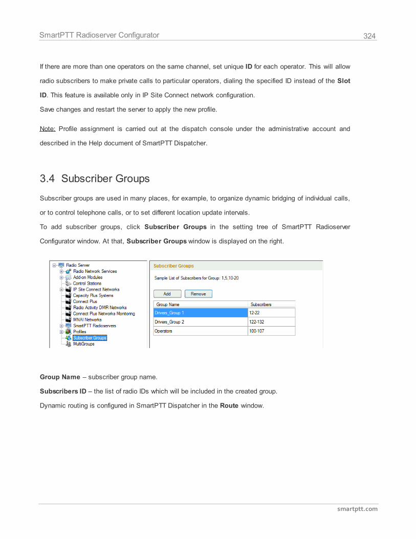
324
smartptt.com
SmartPTT Radioserver Configurator
If there are more than one operators on the same channel, set unique ID for each operator. This will allow
radio subscribers to make private calls to particular operators, dialing the specified ID instead of the Slot
ID. This feature is available only in IP Site Connect network configuration.
Save changes and restart the server to apply the new profile.
Note: Profile assignment is carried out at the dispatch console under the administrative account and
described in the Help document of SmartPTT Dispatcher.
3.4 Subscriber Groups
Subscriber groups are used in many places, for example, to organize dynamic bridging of individual calls,
or to control telephone calls, or to set different location update intervals.
To add subscriber groups, click Subscriber Groups in the setting tree of SmartPTT Radioserver
Configurator window. At that, Subscriber Groups window is displayed on the right.
Group Name – subscriber group name.
Subscribers ID – the list of radio IDs which will be included in the created group.
Dynamic routing is configured in SmartPTT Dispatcher in the Route window.
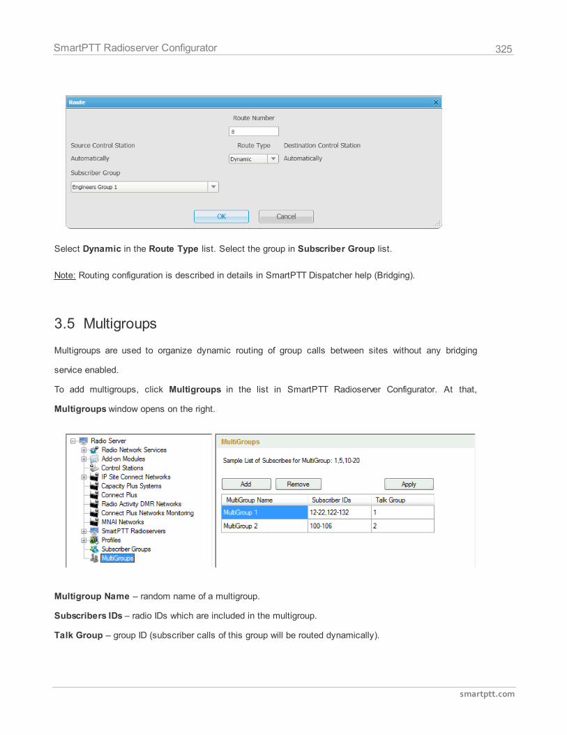
325
smartptt.com
SmartPTT Radioserver Configurator
Select Dynamic in the Route Type list. Select the group in Subscriber Group list.
Note: Routing configuration is described in details in SmartPTT Dispatcher help (Bridging).
3.5 Multigroups
Multigroups are used to organize dynamic routing of group calls between sites without any bridging
service enabled.
To add multigroups, click Multigroups in the list in SmartPTT Radioserver Configurator. At that,
Multigroups window opens on the right.
Multigroup Name – random name of a multigroup.
Subscribers IDs – radio IDs which are included in the multigroup.
Talk Group – group ID (subscriber calls of this group will be routed dynamically).
326
smartptt.com
SmartPTT Radioserver Configurator
There can be the following scenarios:
1. The initiator of the group call belongs to the multigroup;
2. The initiator of the group call does not belong to the multigroup;
3. The initiator of the group call does not belong to the multigroup, but at least one subscriber, to
whom the call is addressed, belongs to the multigroup.
1) If a group call is initiated by the subscriber included in the multigroup, this group call will be
passed to all of the radios from the same talk group on all time slots and regardless of the
IP Site Connect system.
2) If a group call is initiated by the subscriber which is not included in the multigroup, this
group call will be passed only to the subscribers of the group from the same time slot,
which the initiator of the call is currently using.
3) If a group call is initiated by the subscriber which is not included in the multigroup, and
there is one or more subscribers who are included in the multigroup, this group call will be
passed to all of the radios from the same talk group on all time slots and regardless of the
IP Site Connect system.
Note: When you add, change or delete a multigroup, it is not necessary to restart the radioserver. Click
Apply to make multigroup settings come into effect.
3.6 Rules
SmartPTT Radioserver provides the opportunity to set rules on a wide range of criteria and perform
actions (playback sounds, send messages) upon the occurrence of events specified by the rules. This
functionality is available in the Rules tab of SmartPTT Radioserver Configurator.
To setup rules, open the Rules tab in SmartPTT Radioserver Configurator.
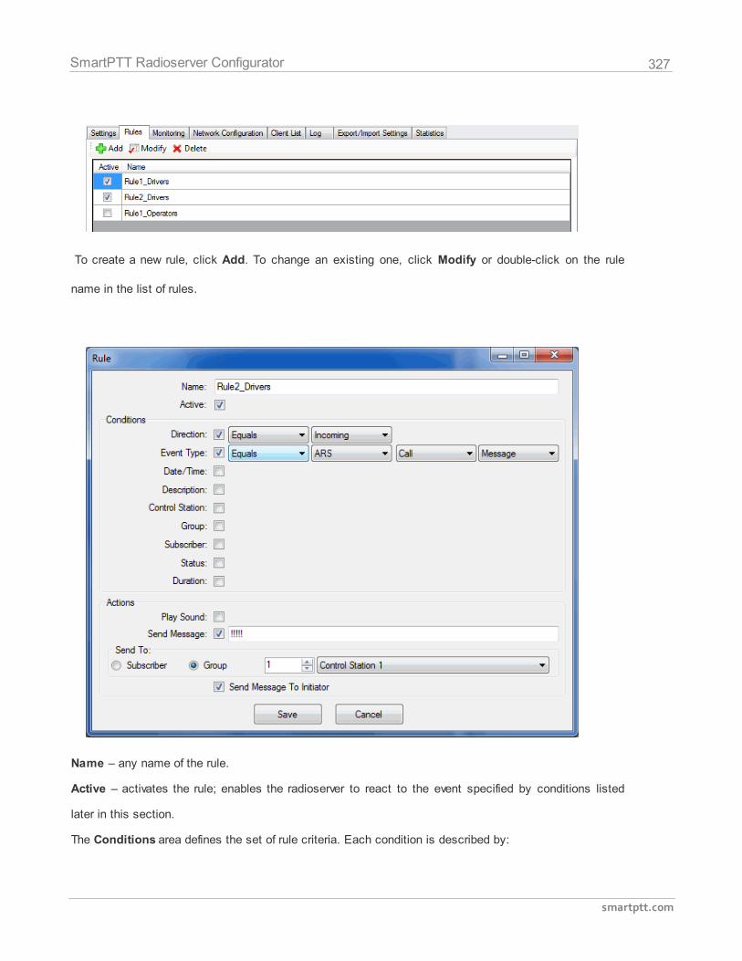
327
smartptt.com
SmartPTT Radioserver Configurator
To create a new rule, click Add. To change an existing one, click Modify or double-click on the rule
name in the list of rules.
Name – any name of the rule.
Active – activates the rule; enables the radioserver to react to the event specified by conditions listed
later in this section.
The Conditions area defines the set of rule criteria. Each condition is described by:
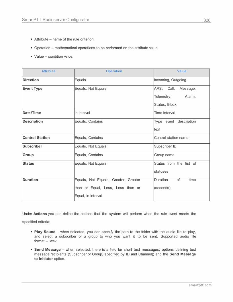
328
smartptt.com
SmartPTT Radioserver Configurator
Attribute – name of the rule criterion.
Operation – mathematical operations to be performed on the attribute value.
Value – condition value.
Attribute Operation Value
Direction Equals Incoming, Outgoing
Event Type Equals, Not Equals ARS, Call, Message,
Telemetry, Alarm,
Status, Block
Date/Time In Interval Time interval
Description Equals, Contains Type event description
text
Control Station Equals, Contains Control station name
Subscriber Equals, Not Equals Subscriber ID
Group Equals, Contains Group name
Status Equals, Not Equals Status from the list of
statuses
Duration Equals, Not Equals, Greater, Greater
than or Equal, Less, Less than or
Equal, In Interval
Duration of time
(seconds)
Under Actions you can define the actions that the system will perform when the rule event meets the
specified criteria:
Play Sound – when selected, you can specify the path to the folder with the audio file to play,and select a subscriber or a group to who you want it to be sent. Supported audio fileformat – .wav.
Send Message – when selected, there is a field for short text messages; options defining textmessage recipients (Subscriber or Group, specified by ID and Channel); and the Send Messageto Initiator option.
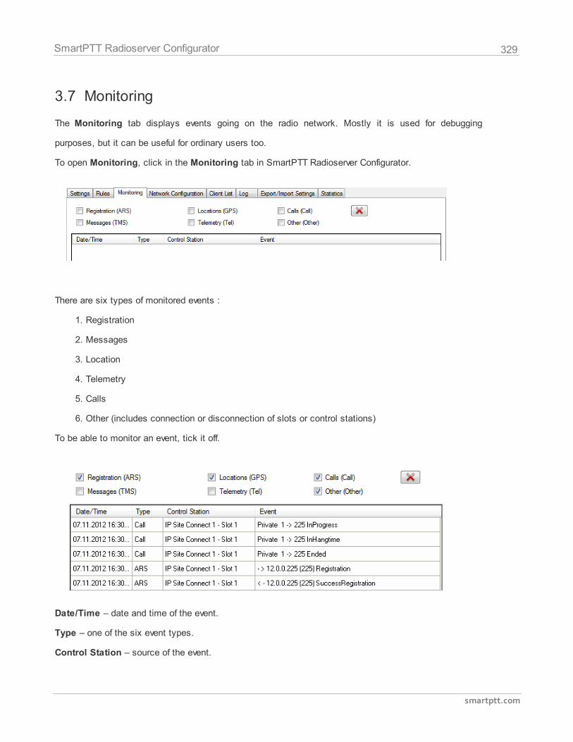
329
smartptt.com
SmartPTT Radioserver Configurator
3.7 Monitoring
The Monitoring tab displays events going on the radio network. Mostly it is used for debugging
purposes, but it can be useful for ordinary users too.
To open Monitoring, click in the Monitoring tab in SmartPTT Radioserver Configurator.
There are six types of monitored events :
1. Registration
2. Messages
3. Location
4. Telemetry
5. Calls
6. Other (includes connection or disconnection of slots or control stations)
To be able to monitor an event, tick it off.
Date/Time – date and time of the event.
Type – one of the six event types.
Control Station – source of the event.
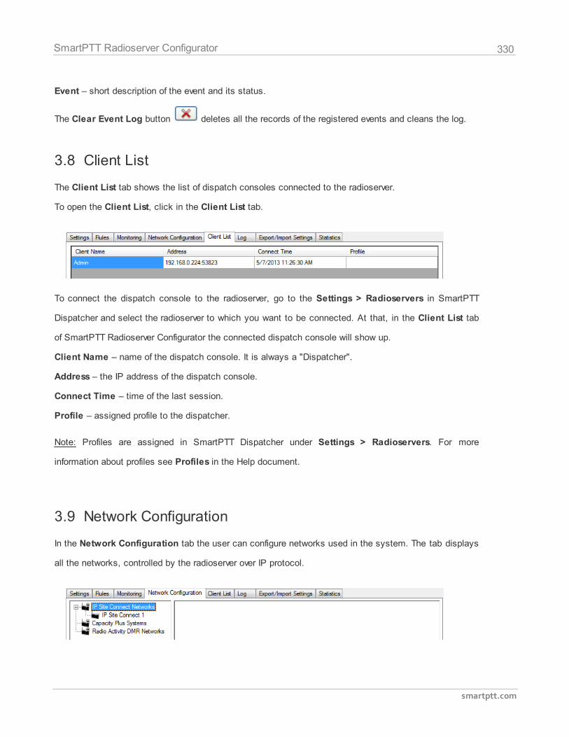
330
smartptt.com
SmartPTT Radioserver Configurator
Event – short description of the event and its status.
The Clear Event Log button deletes all the records of the registered events and cleans the log.
3.8 Client List
The Client List tab shows the list of dispatch consoles connected to the radioserver.
To open the Client List, click in the Client List tab.
To connect the dispatch console to the radioserver, go to the Settings > Radioservers in SmartPTT
Dispatcher and select the radioserver to which you want to be connected. At that, in the Client List tab
of SmartPTT Radioserver Configurator the connected dispatch console will show up.
Client Name – name of the dispatch console. It is always a "Dispatcher".
Address – the IP address of the dispatch console.
Connect Time – time of the last session.
Profile – assigned profile to the dispatcher.
Note: Profiles are assigned in SmartPTT Dispatcher under Settings > Radioservers. For more
information about profiles see Profiles in the Help document.
3.9 Network Configuration
In the Network Configuration tab the user can configure networks used in the system. The tab displays
all the networks, controlled by the radioserver over IP protocol.
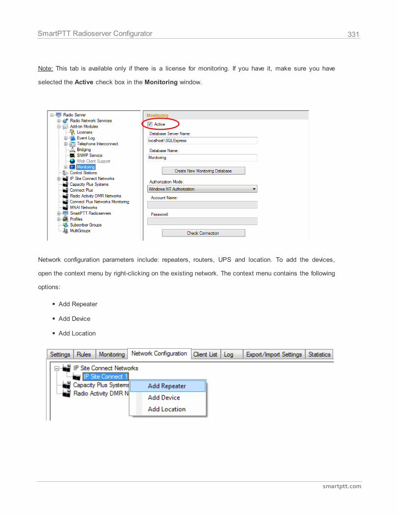
331
smartptt.com
SmartPTT Radioserver Configurator
Note: This tab is available only if there is a license for monitoring. If you have it, make sure you have
selected the Active check box in the Monitoring window.
Network configuration parameters include: repeaters, routers, UPS and location. To add the devices,
open the context menu by right-clicking on the existing network. The context menu contains the following
options:
Add Repeater
Add Device
Add Location
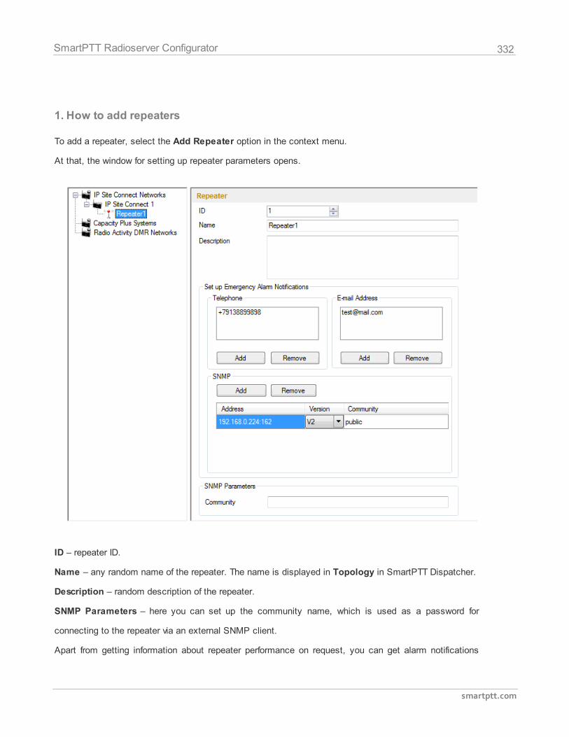
332
smartptt.com
SmartPTT Radioserver Configurator
1. How to add repeaters
To add a repeater, select the Add Repeater option in the context menu.
At that, the window for setting up repeater parameters opens.
ID – repeater ID.
Name – any random name of the repeater. The name is displayed in Topology in SmartPTT Dispatcher.
Description – random description of the repeater.
SNMP Parameters – here you can set up the community name, which is used as a password for
connecting to the repeater via an external SNMP client.
Apart from getting information about repeater performance on request, you can get alarm notifications
333
smartptt.com
SmartPTT Radioserver Configurator
from the repeater as soon as malfunctioning or errors are observed by the repeater. You can decide how
to get the information: you can have it sent to your email, your cell phone or to an SNMP clinet. To do
that, use the Set Up Emergancy Alarm Notifications area.
For the email or cell phone, click Add under the box you need and add the telephone number or the
email address.
For the SNMP client fill the following fields:
Address – address and port of the PC which must receive the data. Use port 162 as default. Remember
to have SNMP client installed on the PC.
Version – version of the SNMP data received. The SNMP client must be able to read it.
Community – community name, which is used as password for connecting to the SNMP client on the
machine.
2. How to add UPS and routers
The supported devices include a router and an uninterruptable power supply (UPS).
To add a device, select the Add Device option in the context menu.
At that, the following window opens.
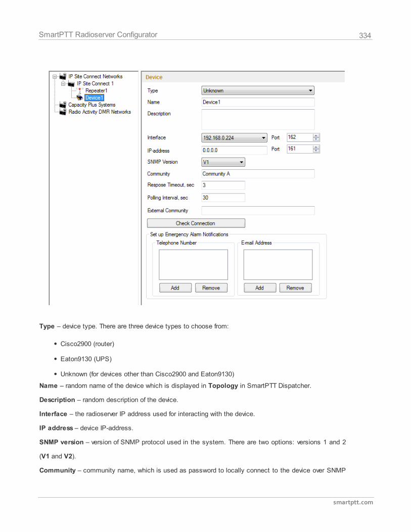
334
smartptt.com
SmartPTT Radioserver Configurator
Type – device type. There are three device types to choose from:
Cisco2900 (router)
Eaton9130 (UPS)
Unknown (for devices other than Cisco2900 and Eaton9130)
Name – random name of the device which is displayed in Topology in SmartPTT Dispatcher.
Description – random description of the device.
Interface – the radioserver IP address used for interacting with the device.
IP address – device IP-address.
SNMP version – version of SNMP protocol used in the system. There are two options: versions 1 and 2
(V1 and V2).
Community – community name, which is used as password to locally connect to the device over SNMP
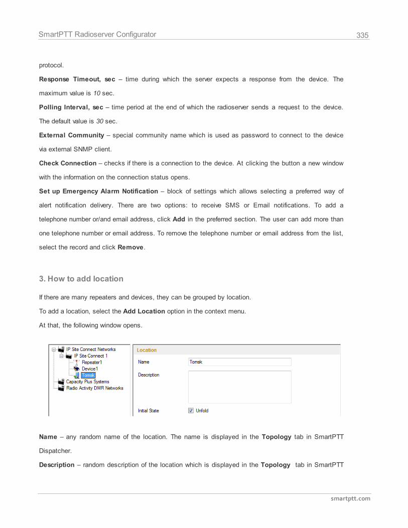
335
smartptt.com
SmartPTT Radioserver Configurator
protocol.
Response Timeout, sec – time during which the server expects a response from the device. The
maximum value is 10 sec.
Polling Interval, sec – time period at the end of which the radioserver sends a request to the device.
The default value is 30 sec.
External Community – special community name which is used as password to connect to the device
via external SNMP client.
Check Connection – checks if there is a connection to the device. At clicking the button a new window
with the information on the connection status opens.
Set up Emergency Alarm Notification – block of settings which allows selecting a preferred way of
alert notification delivery. There are two options: to receive SMS or Email notifications. To add a
telephone number or/and email address, click Add in the preferred section. The user can add more than
one telephone number or email address. To remove the telephone number or email address from the list,
select the record and click Remove.
3. How to add location
If there are many repeaters and devices, they can be grouped by location.
To add a location, select the Add Location option in the context menu.
At that, the following window opens.
Name – any random name of the location. The name is displayed in the Topology tab in SmartPTT
Dispatcher.
Description – random description of the location which is displayed in the Topology tab in SmartPTT
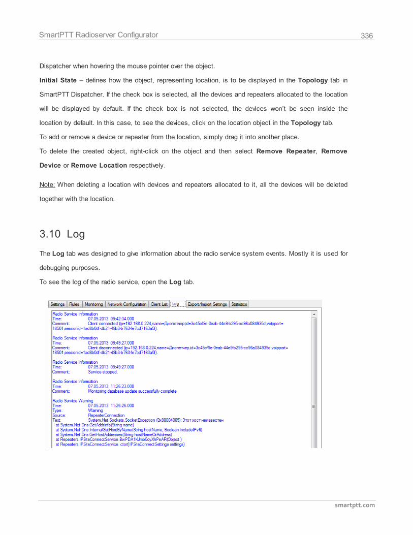
336
smartptt.com
SmartPTT Radioserver Configurator
Dispatcher when hovering the mouse pointer over the object.
Initial State – defines how the object, representing location, is to be displayed in the Topology tab in
SmartPTT Dispatcher. If the check box is selected, all the devices and repeaters allocated to the location
will be displayed by default. If the check box is not selected, the devices won’t be seen inside the
location by default. In this case, to see the devices, click on the location object in the Topology tab.
To add or remove a device or repeater from the location, simply drag it into another place.
To delete the created object, right-click on the object and then select Remove Repeater, Remove
Device or Remove Location respectively.
Note: When deleting a location with devices and repeaters allocated to it, all the devices will be deleted
together with the location.
3.10 Log
The Log tab was designed to give information about the radio service system events. Mostly it is used for
debugging purposes.
To see the log of the radio service, open the Log tab.
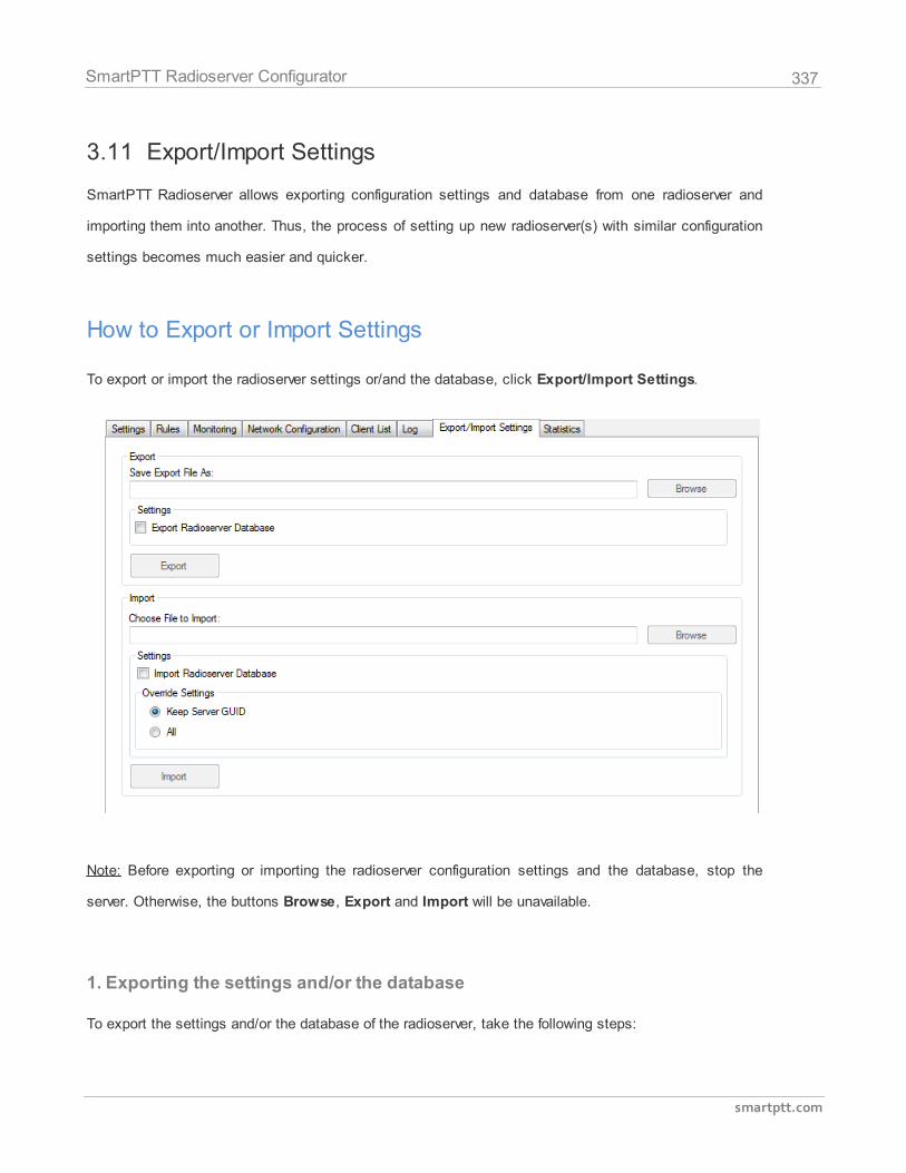
337
smartptt.com
SmartPTT Radioserver Configurator
3.11 Export/Import Settings
SmartPTT Radioserver allows exporting configuration settings and database from one radioserver and
importing them into another. Thus, the process of setting up new radioserver(s) with similar configuration
settings becomes much easier and quicker.
How to Export or Import Settings
To export or import the radioserver settings or/and the database, click Export/Import Settings.
Note: Before exporting or importing the radioserver configuration settings and the database, stop the
server. Otherwise, the buttons Browse, Export and Import will be unavailable.
1. Exporting the settings and/or the database
To export the settings and/or the database of the radioserver, take the following steps:
338
smartptt.com
SmartPTT Radioserver Configurator
1. Stop the radioserver.
2. Select the file where you want the settings to be exported by entering the path to the file in the
Save Export File As field or by clicking Browse.
3. Select Export Radioserver Database if you want the database to be exported too.
4. Click Export.
Note: You cannot export the radioserver database separately, that is without the settings.
2. Importing the settings and/or the database
To import the settings and/or the database to the radioserver, take the following steps:
1. Stop the radioserver.
2. Select the file from where you want the settings to be imported by entering the path to the file in
the Choose File to Import field or by clicking Browse.
3. Select Import Radioserver Database if you want the database to be imported too.
4. Select the import mode:
1) Keep Server GUID – import mode when the server globally unique ID is left unchanged.
After importing, there are two servers with same configuration settings, but different globally
unique GUID’s.
2) All – import mode when all the server configuration settings, including the GUID, are
replaced with the imported values. After importing, there are two servers with absolutely
identical settings and GUID’s.
5. Click Import.
Note: After importing the radioserver settings with the option to override all the existing settings (All), it is
important to delete one of the two servers to avoid GUID conflict.
3.12 Statistics
The Statistics tab was designed to give you information on:
1. The total number of events taking place on the radioserver.
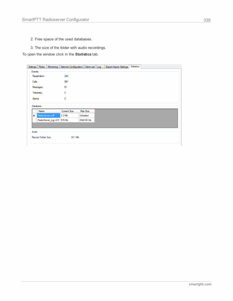
339
smartptt.com
SmartPTT Radioserver Configurator
2. Free space of the used databases.
3. The size of the folder with audio recordings.
To open the window click in the Statistics tab.
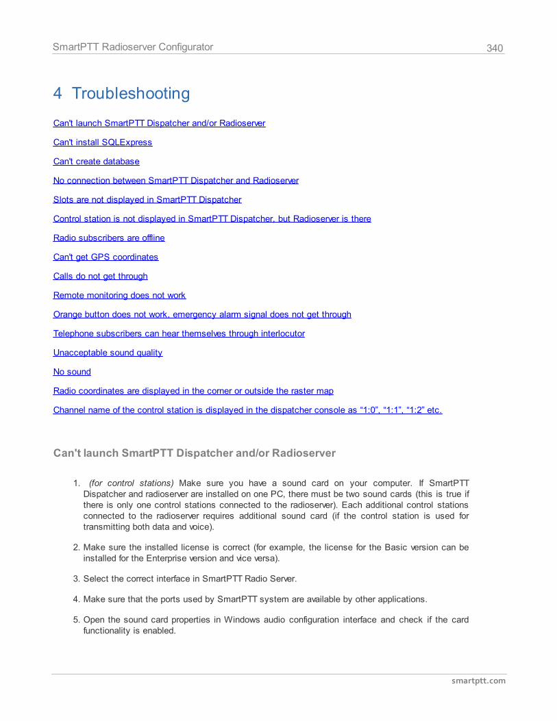
340
smartptt.com
SmartPTT Radioserver Configurator
4 Troubleshooting
Can't launch SmartPTT Dispatcher and/or Radioserver
Can't install SQLExpress
Can't create database
No connection between SmartPTT Dispatcher and Radioserver
Slots are not displayed in SmartPTT Dispatcher
Control station is not displayed in SmartPTT Dispatcher, but Radioserver is there
Radio subscribers are offline
Can't get GPS coordinates
Calls do not get through
Remote monitoring does not work
Orange button does not work, emergency alarm signal does not get through
Telephone subscribers can hear themselves through interlocutor
Unacceptable sound quality
No sound
Radio coordinates are displayed in the corner or outside the raster map
Channel name of the control station is displayed in the dispatcher console as “1:0”, “1:1”, “1:2” etc.
Can't launch SmartPTT Dispatcher and/or Radioserver
1. (for control stations) Make sure you have a sound card on your computer. If SmartPTTDispatcher and radioserver are installed on one PC, there must be two sound cards (this is true ifthere is only one control stations connected to the radioserver). Each additional control stationsconnected to the radioserver requires additional sound card (if the control station is used fortransmitting both data and voice).
2. Make sure the installed license is correct (for example, the license for the Basic version can beinstalled for the Enterprise version and vice versa).
3. Select the correct interface in SmartPTT Radio Server.
4. Make sure that the ports used by SmartPTT system are available by other applications.
5. Open the sound card properties in Windows audio configuration interface and check if the cardfunctionality is enabled.
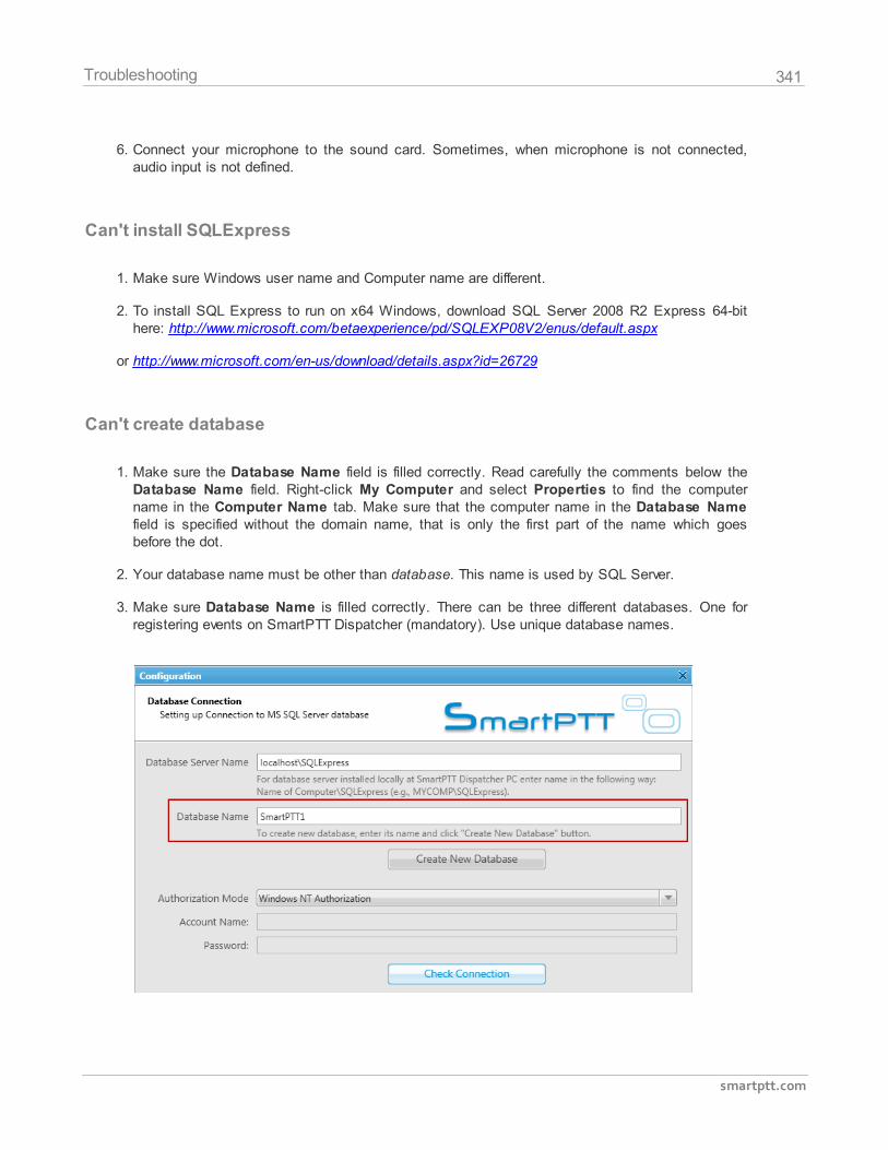
341
smartptt.com
Troubleshooting
6. Connect your microphone to the sound card. Sometimes, when microphone is not connected,audio input is not defined.
Can't install SQLExpress
1. Make sure Windows user name and Computer name are different.
2. To install SQL Express to run on x64 Windows, download SQL Server 2008 R2 Express 64-bithere: http://www.microsoft.com/betaexperience/pd/SQLEXP08V2/enus/default.aspx
or http://www.microsoft.com/en-us/download/details.aspx?id=26729
Can't create database
1. Make sure the Database Name field is filled correctly. Read carefully the comments below theDatabase Name field. Right-click My Computer and select Properties to find the computername in the Computer Name tab. Make sure that the computer name in the Database Namefield is specified without the domain name, that is only the first part of the name which goesbefore the dot.
2. Your database name must be other than database. This name is used by SQL Server.
3. Make sure Database Name is filled correctly. There can be three different databases. One forregistering events on SmartPTT Dispatcher (mandatory). Use unique database names.
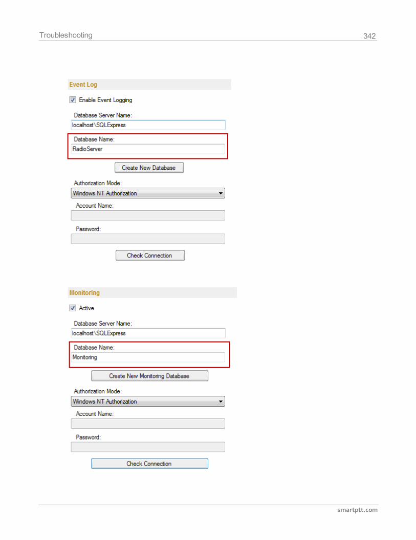
342
smartptt.com
Troubleshooting
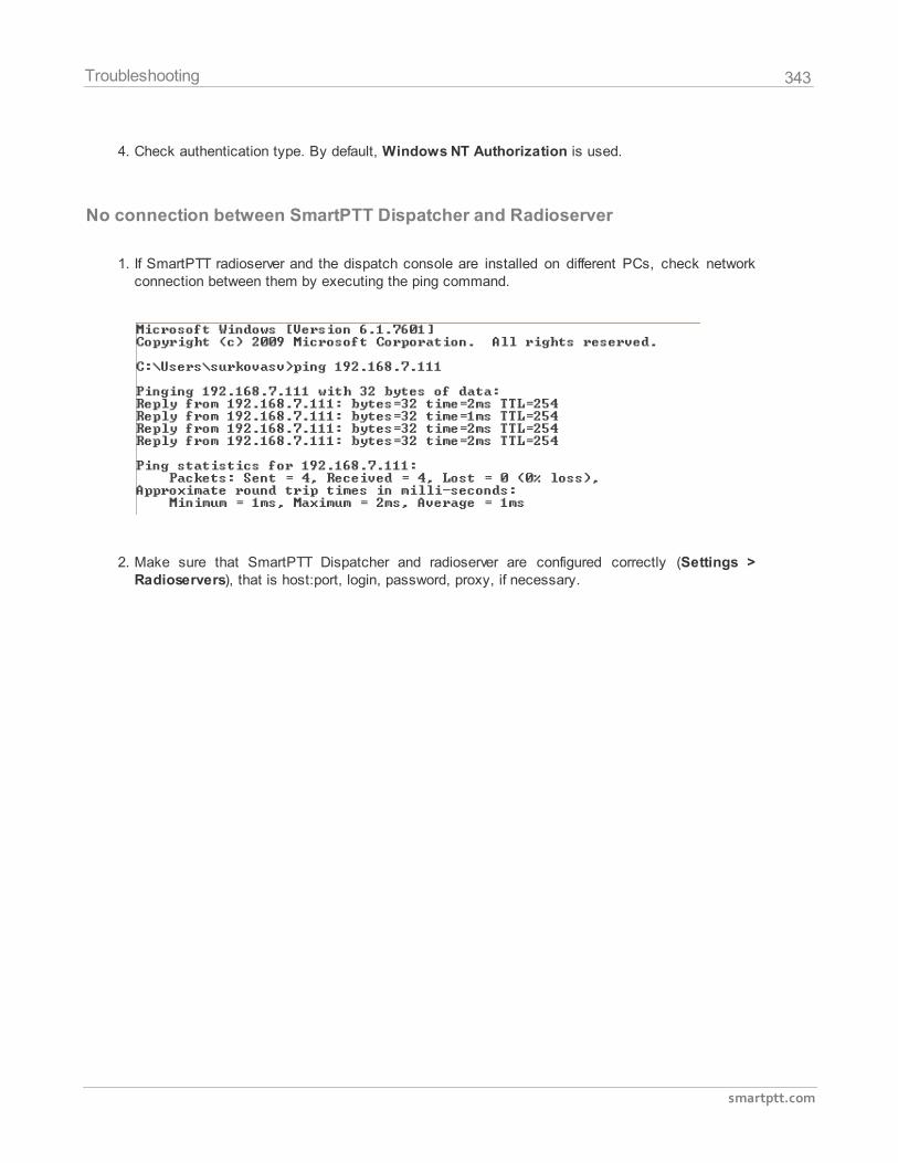
343
smartptt.com
Troubleshooting
4. Check authentication type. By default, Windows NT Authorization is used.
No connection between SmartPTT Dispatcher and Radioserver
1. If SmartPTT radioserver and the dispatch console are installed on different PCs, check networkconnection between them by executing the ping command.
2. Make sure that SmartPTT Dispatcher and radioserver are configured correctly (Settings >Radioservers), that is host:port, login, password, proxy, if necessary.
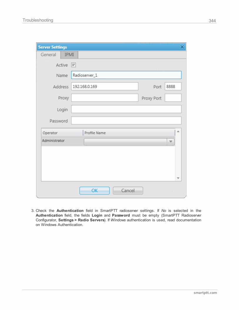
344
smartptt.com
Troubleshooting
3. Check the Authentication field in SmartPTT radioserver settings. If No is selected in theAuthentication field, the fields Login and Password must be empty (SmartPTT RadioserverConfigurator, Settings > Radio Servers). If Windows authentication is used, read documentationon Windows Authentication.
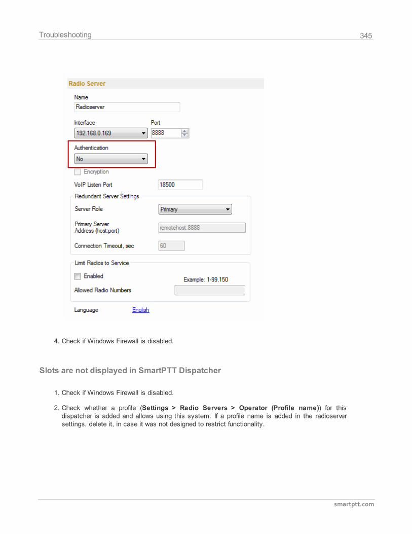
345
smartptt.com
Troubleshooting
4. Check if Windows Firewall is disabled.
Slots are not displayed in SmartPTT Dispatcher
1. Check if Windows Firewall is disabled.
2. Check whether a profile (Settings > Radio Servers > Operator (Profile name)) for thisdispatcher is added and allows using this system. If a profile name is added in the radioserversettings, delete it, in case it was not designed to restrict functionality.
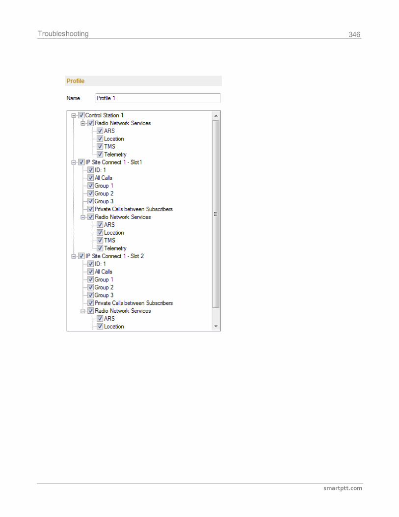
346
smartptt.com
Troubleshooting
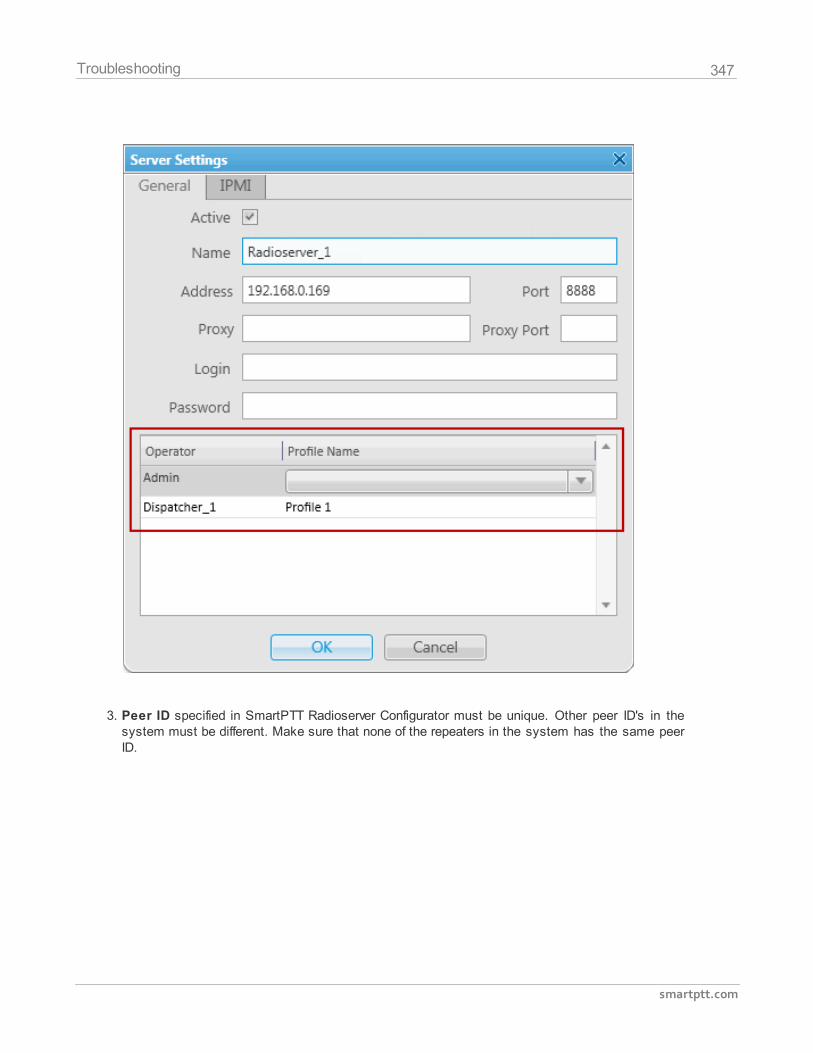
347
smartptt.com
Troubleshooting
3. Peer ID specified in SmartPTT Radioserver Configurator must be unique. Other peer ID's in thesystem must be different. Make sure that none of the repeaters in the system has the same peerID.
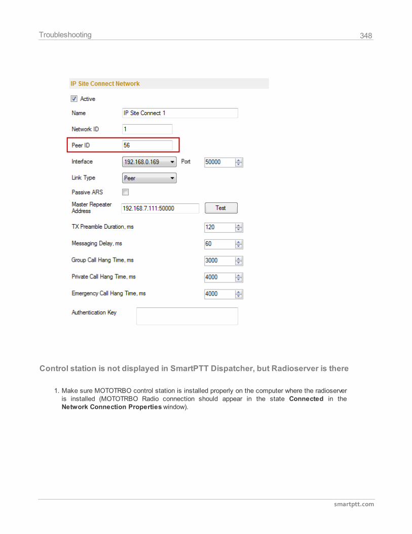
348
smartptt.com
Troubleshooting
Control station is not displayed in SmartPTT Dispatcher, but Radioserver is there
1. Make sure MOTOTRBO control station is installed properly on the computer where the radioserveris installed (MOTOTRBO Radio connection should appear in the state Connected in theNetwork Connection Properties window).
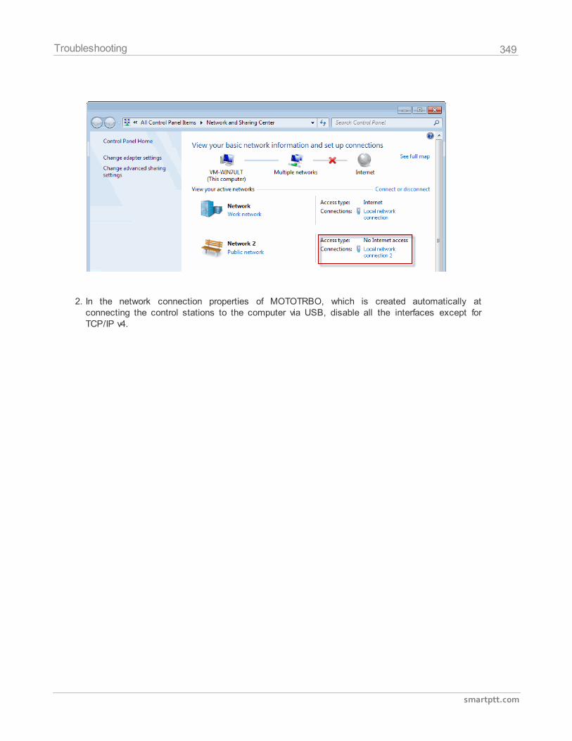
349
smartptt.com
Troubleshooting
2. In the network connection properties of MOTOTRBO, which is created automatically atconnecting the control stations to the computer via USB, disable all the interfaces except forTCP/IP v4.
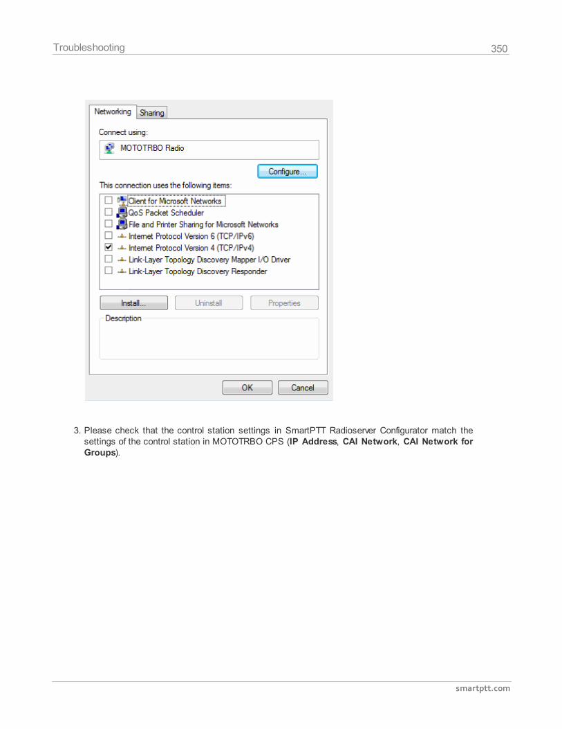
350
smartptt.com
Troubleshooting
3. Please check that the control station settings in SmartPTT Radioserver Configurator match thesettings of the control station in MOTOTRBO CPS (IP Address, CAI Network, CAI Network forGroups).
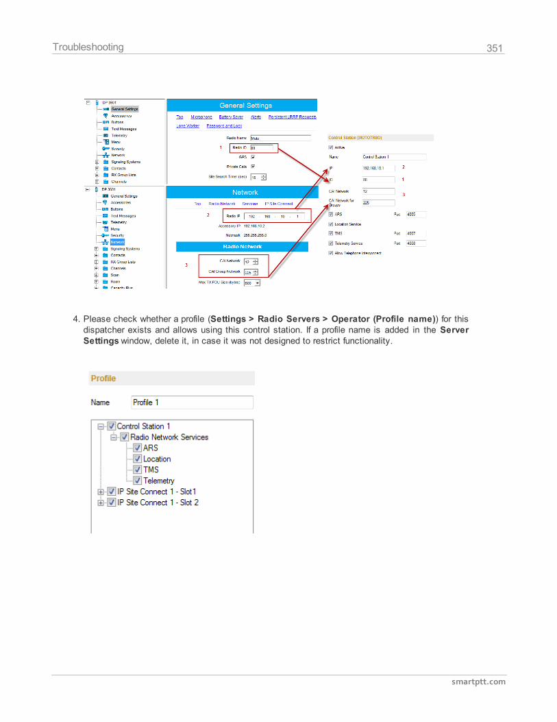
351
smartptt.com
Troubleshooting
4. Please check whether a profile (Settings > Radio Servers > Operator (Profile name)) for thisdispatcher exists and allows using this control station. If a profile name is added in the ServerSettings window, delete it, in case it was not designed to restrict functionality.
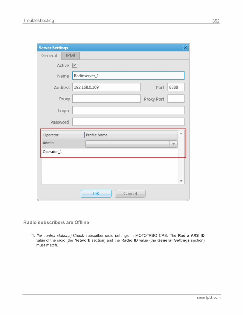
352
smartptt.com
Troubleshooting
Radio subscribers are Offline
1. (for control stations) Check subscriber radio settings in MOTOTRBO CPS. The Radio ARS IDvalue of the radio (the Network section) and the Radio ID value (the General Settings section)must match.
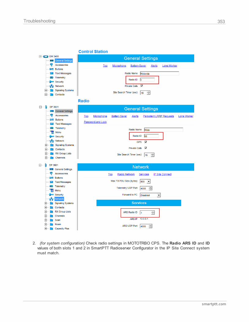
353
smartptt.com
Troubleshooting
2. (for system configuration) Check radio settings in MOTOTRBO CPS. The Radio ARS ID and IDvalues of both slots 1 and 2 in SmartPTT Radioserver Configurator in the IP Site Connect systemmust match.
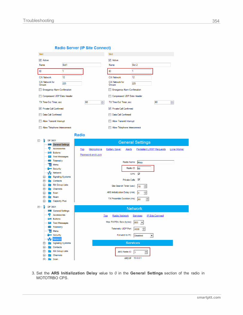
354
smartptt.com
Troubleshooting
3. Set the ARS Initialization Delay value to 0 in the General Settings section of the radio inMOTOTRBO CPS.
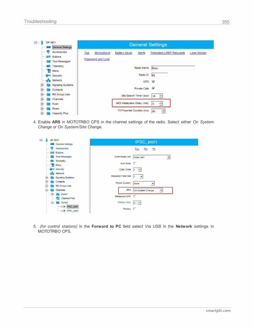
355
smartptt.com
Troubleshooting
4. Enable ARS in MOTOTRBO CPS in the channel settings of the radio. Select either On SystemChange or On System/Site Change.
5. (for control stations) In the Forward to PC field select Via USB in the Network settings inMOTOTRBO CPS.
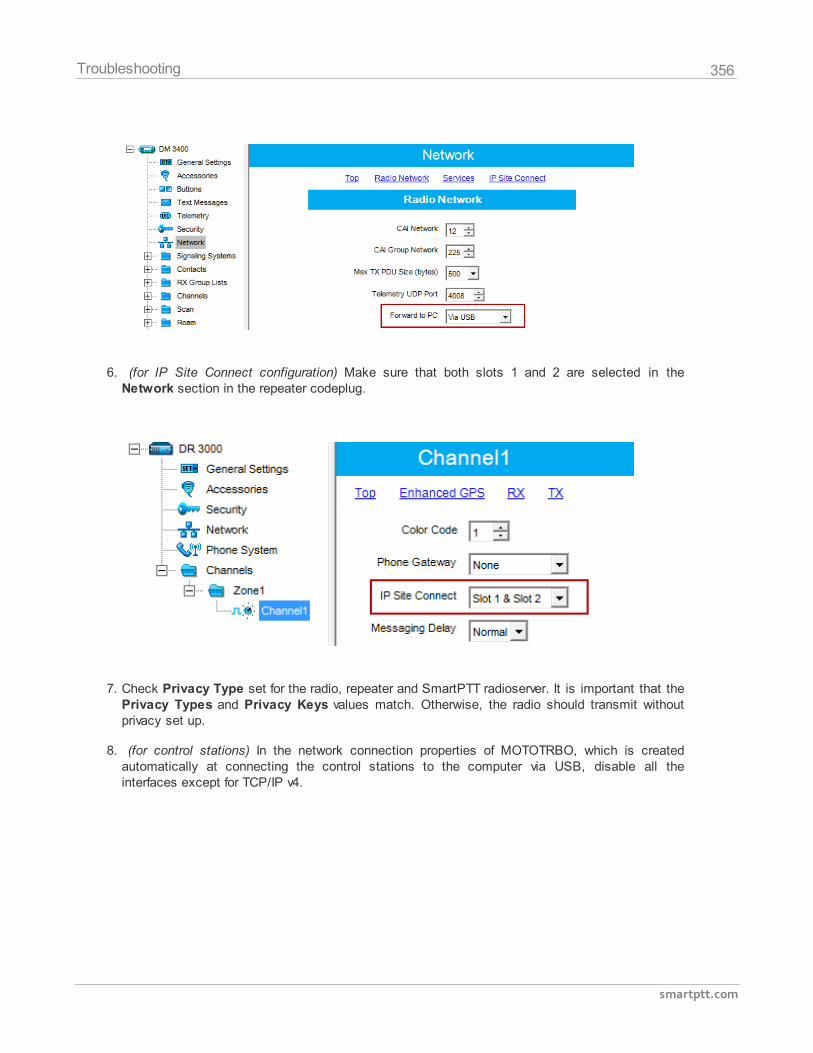
356
smartptt.com
Troubleshooting
6. (for IP Site Connect configuration) Make sure that both slots 1 and 2 are selected in theNetwork section in the repeater codeplug.
7. Check Privacy Type set for the radio, repeater and SmartPTT radioserver. It is important that thePrivacy Types and Privacy Keys values match. Otherwise, the radio should transmit withoutprivacy set up.
8. (for control stations) In the network connection properties of MOTOTRBO, which is createdautomatically at connecting the control stations to the computer via USB, disable all theinterfaces except for TCP/IP v4.
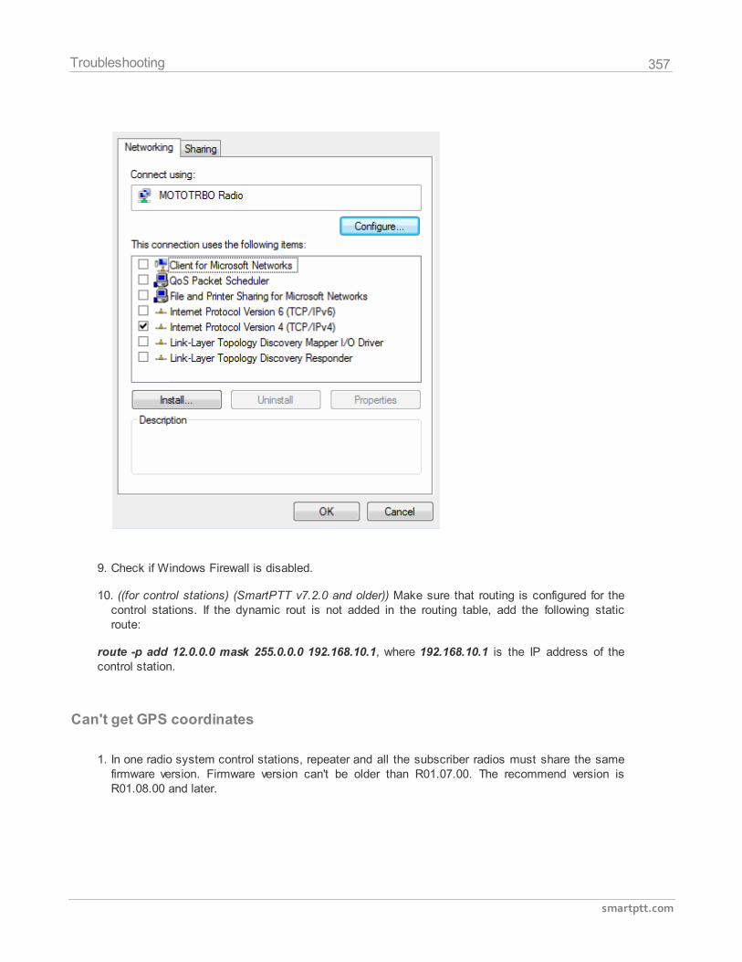
357
smartptt.com
Troubleshooting
9. Check if Windows Firewall is disabled.
10. ((for control stations) (SmartPTT v7.2.0 and older)) Make sure that routing is configured for thecontrol stations. If the dynamic rout is not added in the routing table, add the following staticroute:
route -p add 12.0.0.0 mask 255.0.0.0 192.168.10.1, where 192.168.10.1 is the IP address of thecontrol station.
Can't get GPS coordinates
1. In one radio system control stations, repeater and all the subscriber radios must share the samefirmware version. Firmware version can't be older than R01.07.00. The recommend version isR01.08.00 and later.
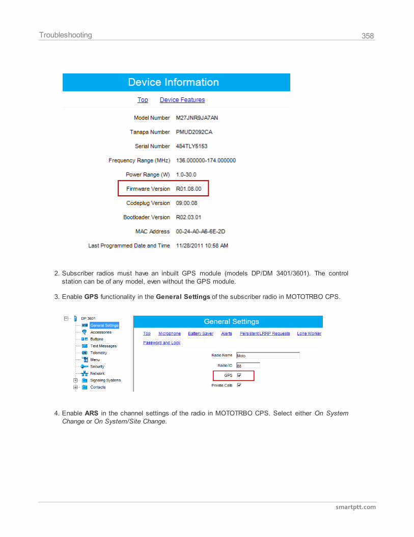
358
smartptt.com
Troubleshooting
2. Subscriber radios must have an inbuilt GPS module (models DP/DM 3401/3601). The controlstation can be of any model, even without the GPS module.
3. Enable GPS functionality in the General Settings of the subscriber radio in MOTOTRBO CPS.
4. Enable ARS in the channel settings of the radio in MOTOTRBO CPS. Select either On SystemChange or On System/Site Change.
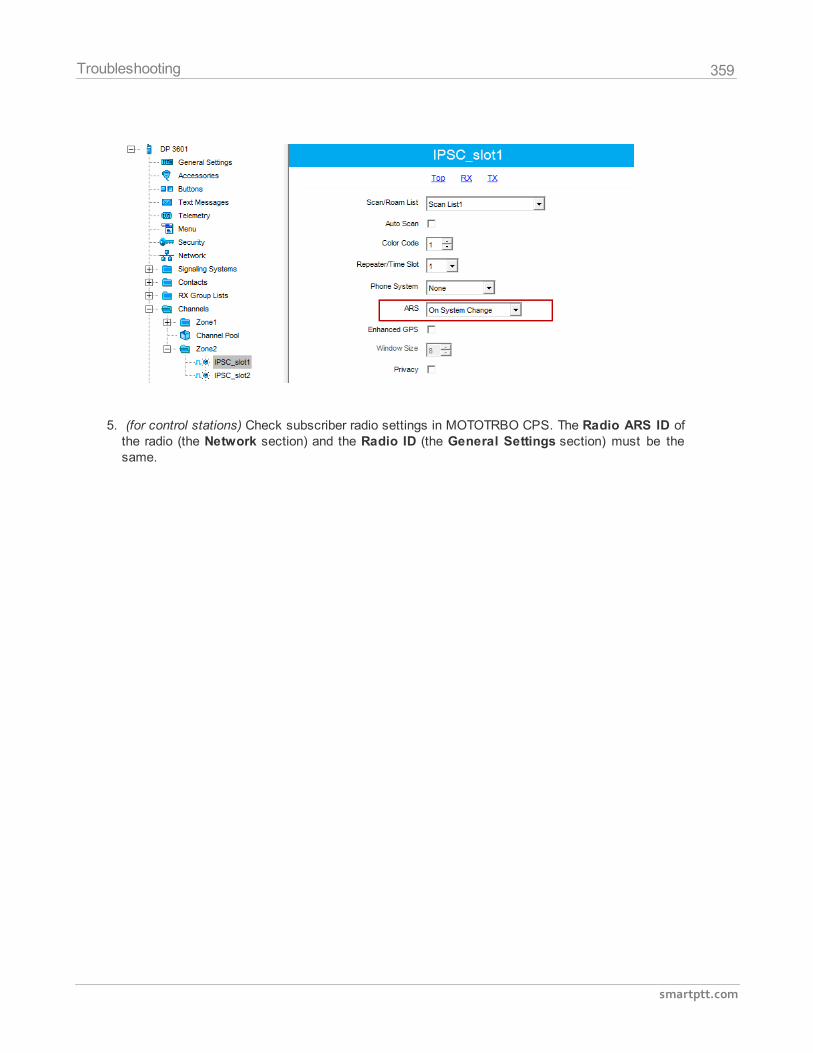
359
smartptt.com
Troubleshooting
5. (for control stations) Check subscriber radio settings in MOTOTRBO CPS. The Radio ARS ID ofthe radio (the Network section) and the Radio ID (the General Settings section) must be thesame.
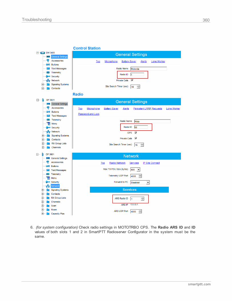
360
smartptt.com
Troubleshooting
6. (for system configuration) Check radio settings in MOTOTRBO CPS. The Radio ARS ID and IDvalues of both slots 1 and 2 in SmartPTT Radioserver Configurator in the system must be thesame.
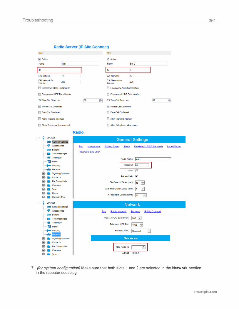
361
smartptt.com
Troubleshooting
7. (for system configuration) Make sure that both slots 1 and 2 are selected in the Network sectionin the repeater codeplug.
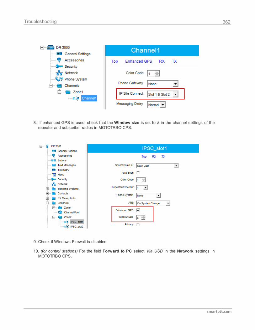
362
smartptt.com
Troubleshooting
8. If enhanced GPS is used, check that the Window size is set to 8 in the channel settings of therepeater and subscriber radios in MOTOTRBO CPS.
9. Check if Windows Firewall is disabled.
10. (for control stations) For the field Forward to PC select Via USB in the Network settings inMOTOTRBO CPS.
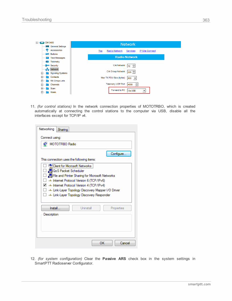
363
smartptt.com
Troubleshooting
11. (for control stations) In the network connection properties of MOTOTRBO, which is createdautomatically at connecting the control stations to the computer via USB, disable all theinterfaces except for TCP/IP v4.
12. (for system configuration) Clear the Passive ARS check box in the system settings inSmartPTT Radioserver Configurator.
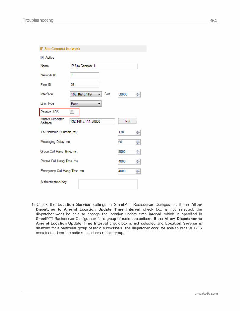
364
smartptt.com
Troubleshooting
13.Check the Location Service settings in SmartPTT Radioserver Configurator. If the AllowDispatcher to Amend Location Update Time Interval check box is not selected, thedispatcher won't be able to change the location update time interval, which is specified inSmartPTT Radioserver Configurator for a group of radio subscribers. If the Allow Dispatcher toAmend Location Update Time Interval check box is not selected and Location Service isdisabled for a particular group of radio subscribers, the dispatcher won't be able to receive GPScoordinates from the radio subscribers of this group.
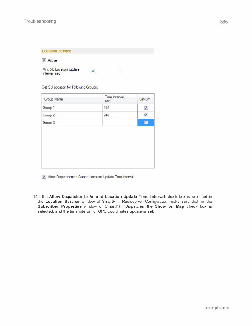
365
smartptt.com
Troubleshooting
14.If the Allow Dispatcher to Amend Location Update Time Interval check box is selected inthe Location Service window of SmartPTT Radioserver Configurator, make sure that in theSubscriber Properties window of SmartPTT Dispatcher the Show on Map check box isselected, and the time interval for GPS coordinates update is set.
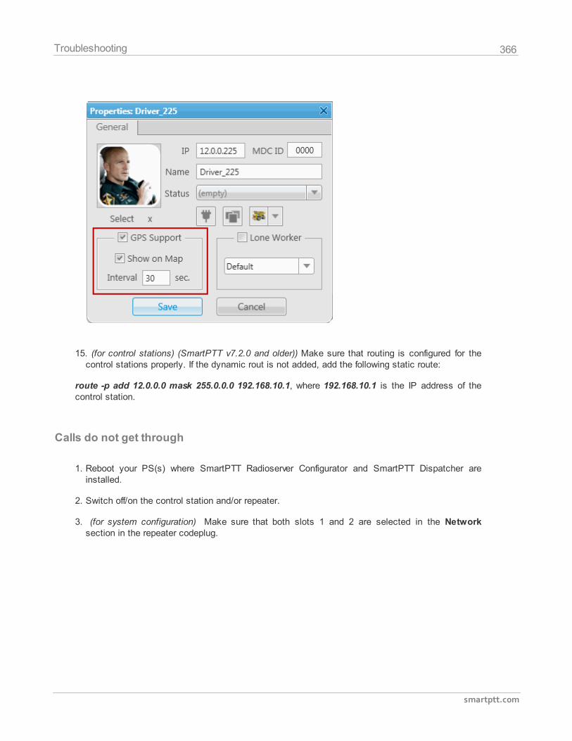
366
smartptt.com
Troubleshooting
15. (for control stations) (SmartPTT v7.2.0 and older)) Make sure that routing is configured for thecontrol stations properly. If the dynamic rout is not added, add the following static route:
route -p add 12.0.0.0 mask 255.0.0.0 192.168.10.1, where 192.168.10.1 is the IP address of thecontrol station.
Calls do not get through
1. Reboot your PS(s) where SmartPTT Radioserver Configurator and SmartPTT Dispatcher areinstalled.
2. Switch off/on the control station and/or repeater.
3. (for system configuration) Make sure that both slots 1 and 2 are selected in the Networksection in the repeater codeplug.
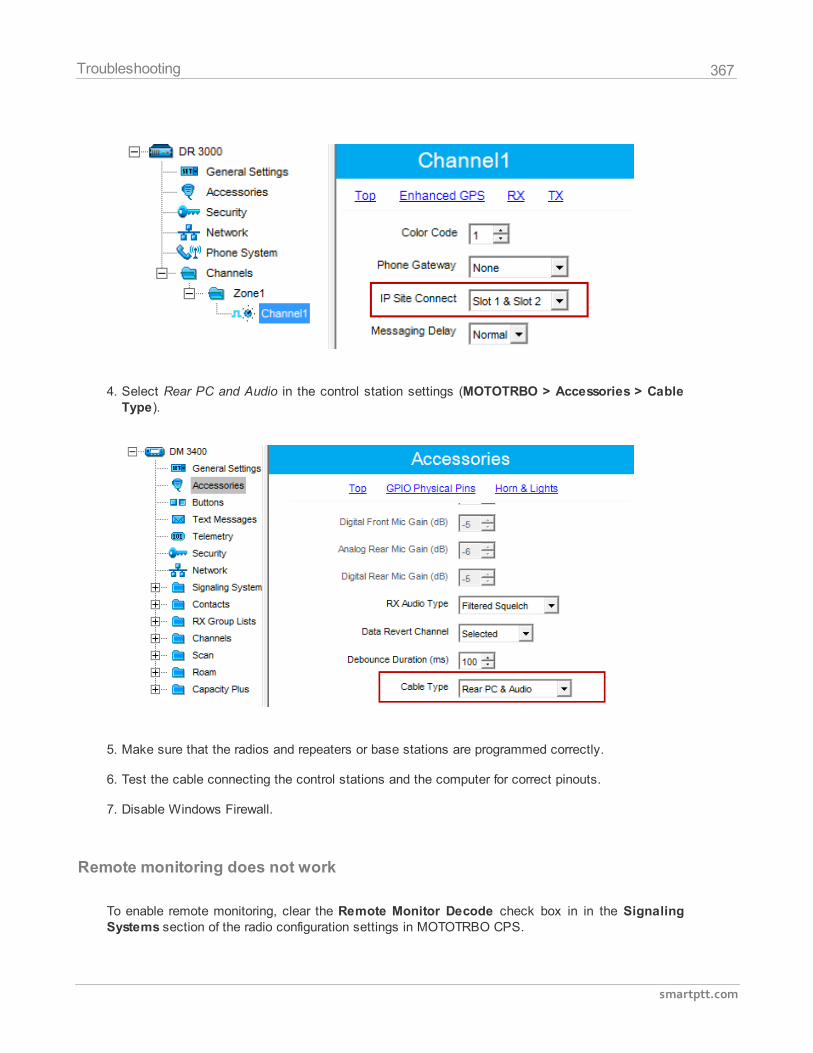
367
smartptt.com
Troubleshooting
4. Select Rear PC and Audio in the control station settings (MOTOTRBO > Accessories > CableType).
5. Make sure that the radios and repeaters or base stations are programmed correctly.
6. Test the cable connecting the control stations and the computer for correct pinouts.
7. Disable Windows Firewall.
Remote monitoring does not work
To enable remote monitoring, clear the Remote Monitor Decode check box in in the SignalingSystems section of the radio configuration settings in MOTOTRBO CPS.
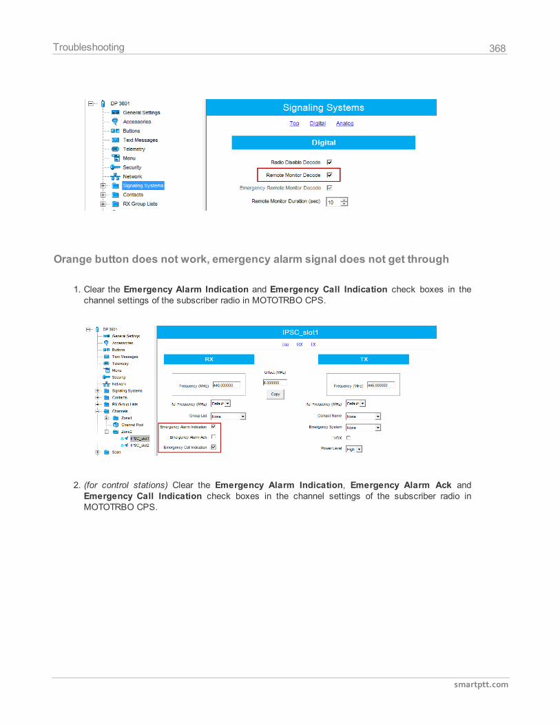
368
smartptt.com
Troubleshooting
Orange button does not work, emergency alarm signal does not get through
1. Clear the Emergency Alarm Indication and Emergency Call Indication check boxes in thechannel settings of the subscriber radio in MOTOTRBO CPS.
2. (for control stations) Clear the Emergency Alarm Indication, Emergency Alarm Ack andEmergency Call Indication check boxes in the channel settings of the subscriber radio inMOTOTRBO CPS.
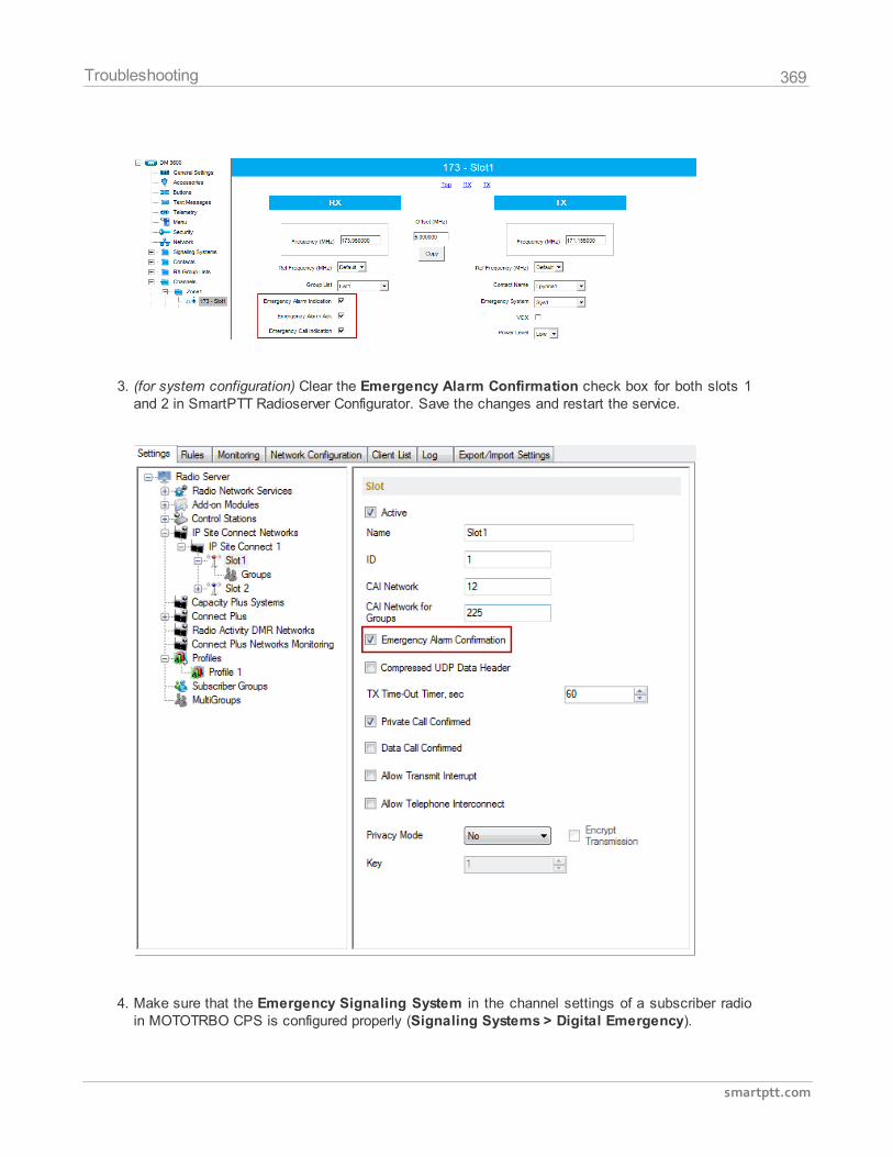
369
smartptt.com
Troubleshooting
3. (for system configuration) Clear the Emergency Alarm Confirmation check box for both slots 1and 2 in SmartPTT Radioserver Configurator. Save the changes and restart the service.
4. Make sure that the Emergency Signaling System in the channel settings of a subscriber radioin MOTOTRBO CPS is configured properly (Signaling Systems > Digital Emergency).
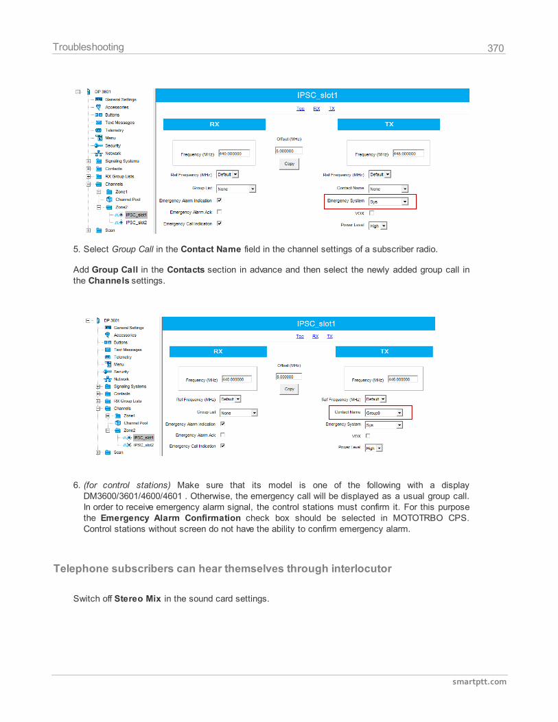
370
smartptt.com
Troubleshooting
5. Select Group Call in the Contact Name field in the channel settings of a subscriber radio.
Add Group Call in the Contacts section in advance and then select the newly added group call inthe Channels settings.
6. (for control stations) Make sure that its model is one of the following with a displayDM3600/3601/4600/4601 . Otherwise, the emergency call will be displayed as a usual group call.In order to receive emergency alarm signal, the control stations must confirm it. For this purposethe Emergency Alarm Confirmation check box should be selected in MOTOTRBO CPS.Control stations without screen do not have the ability to confirm emergency alarm.
Telephone subscribers can hear themselves through interlocutor
Switch off Stereo Mix in the sound card settings.
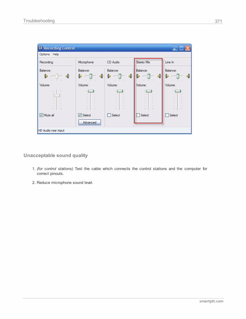
371
smartptt.com
Troubleshooting
Unacceptable sound quality
1. (for control stations) Test the cable which connects the control stations and the computer forcorrect pinouts.
2. Reduce microphone sound level.
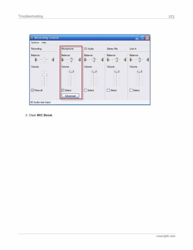
372
smartptt.com
Troubleshooting
3. Clear MIC Boost.
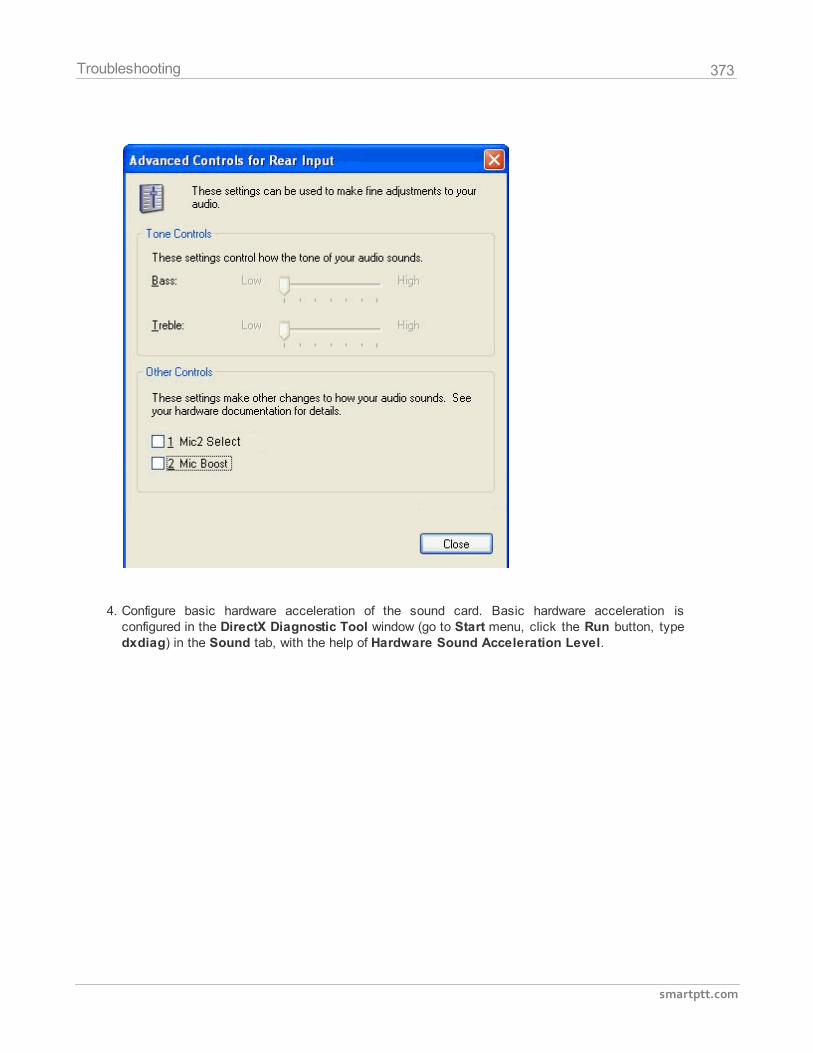
373
smartptt.com
Troubleshooting
4. Configure basic hardware acceleration of the sound card. Basic hardware acceleration isconfigured in the DirectX Diagnostic Tool window (go to Start menu, click the Run button, typedxdiag) in the Sound tab, with the help of Hardware Sound Acceleration Level.
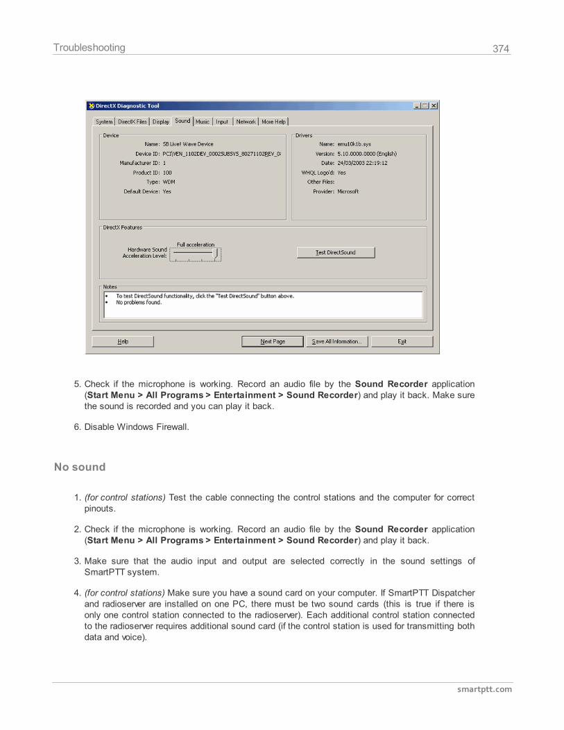
374
smartptt.com
Troubleshooting
5. Check if the microphone is working. Record an audio file by the Sound Recorder application(Start Menu > All Programs > Entertainment > Sound Recorder) and play it back. Make surethe sound is recorded and you can play it back.
6. Disable Windows Firewall.
No sound
1. (for control stations) Test the cable connecting the control stations and the computer for correctpinouts.
2. Check if the microphone is working. Record an audio file by the Sound Recorder application(Start Menu > All Programs > Entertainment > Sound Recorder) and play it back.
3. Make sure that the audio input and output are selected correctly in the sound settings ofSmartPTT system.
4. (for control stations) Make sure you have a sound card on your computer. If SmartPTT Dispatcherand radioserver are installed on one PC, there must be two sound cards (this is true if there isonly one control station connected to the radioserver). Each additional control station connectedto the radioserver requires additional sound card (if the control station is used for transmitting bothdata and voice).
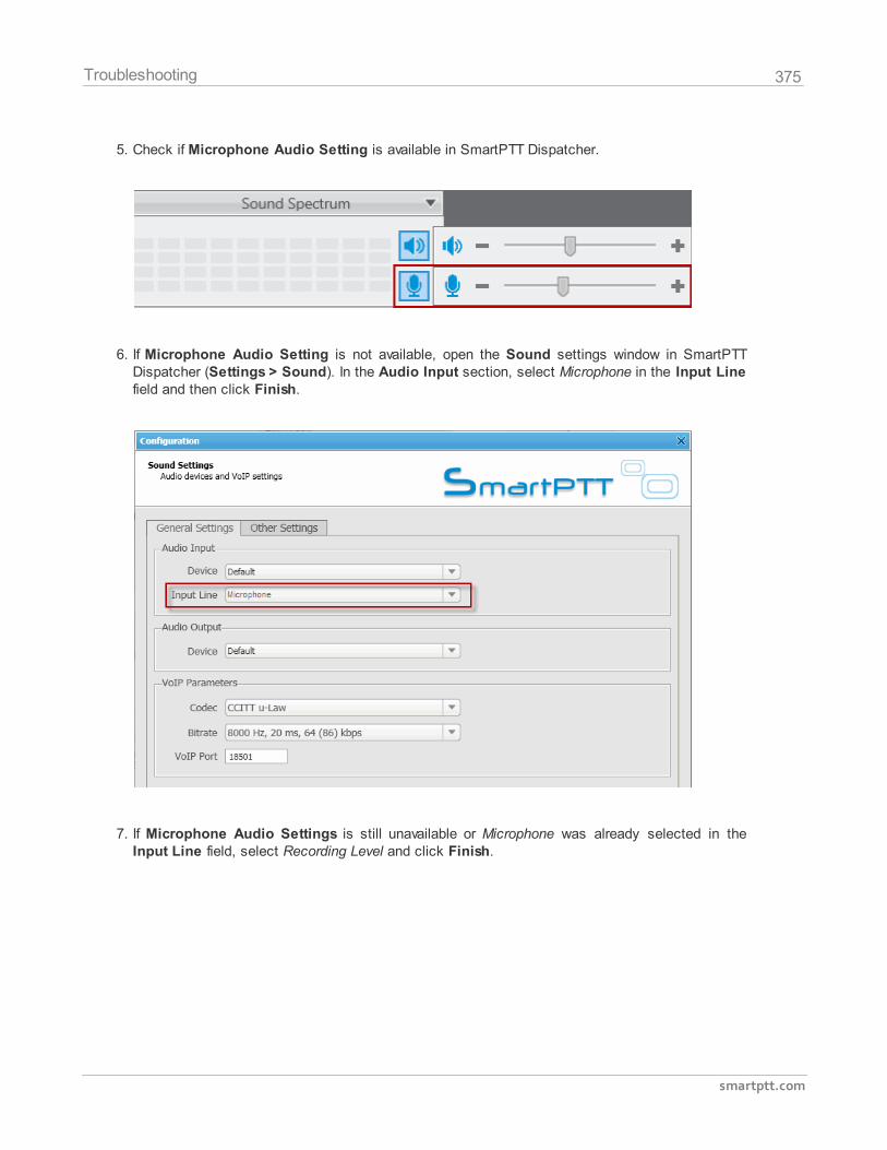
375
smartptt.com
Troubleshooting
5. Check if Microphone Audio Setting is available in SmartPTT Dispatcher.
6. If Microphone Audio Setting is not available, open the Sound settings window in SmartPTTDispatcher (Settings > Sound). In the Audio Input section, select Microphone in the Input Linefield and then click Finish.
7. If Microphone Audio Settings is still unavailable or Microphone was already selected in theInput Line field, select Recording Level and click Finish.
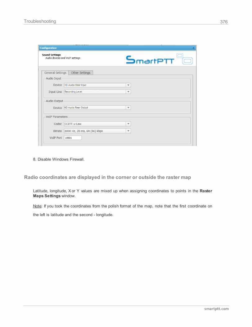
376
smartptt.com
Troubleshooting
8. Disable Windows Firewall.
Radio coordinates are displayed in the corner or outside the raster map
Latitude, longitude, X or Y values are mixed up when assigning coordinates to points in the RasterMaps Settings window.
Note: If you took the coordinates from the polish format of the map, note that the first coordinate on
the left is latitude and the second - longitude.
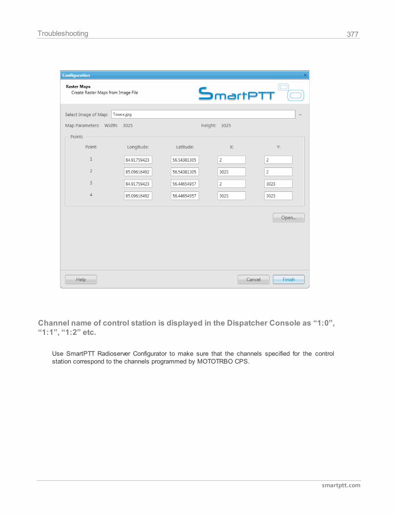
377
smartptt.com
Troubleshooting
Channel name of control station is displayed in the Dispatcher Console as “1:0”,“1:1”, “1:2” etc.
Use SmartPTT Radioserver Configurator to make sure that the channels specified for the controlstation correspond to the channels programmed by MOTOTRBO CPS.