Embed Size (px)
Citation preview
SmartLine RMA Fieldbus Quick Start Installation Guide
34-ST-25-52, Revision 2
Honeywell Process Solutions
This document provides descriptions and procedures for the Quick Installation of Honeywell’s family of SmartLine Remote Indicator.
The SmartLine Remote Indicator is a configurable intelligent field device which functions as an output and status indicator for any Foundation Fieldbus device on the same H1 link. Table 1 lists the protocols, human interface (HMI), materials, approvals, and mounting bracket options.
Various other documents are available on the CD supplied with your shipment. Documents in hardcopy can also be ordered.
Copyrights, Notices and Trademarks Copyright 2014 by Honeywell Revision 2, September 2014 Trademarks SmartLine, RMA are U.S. registered trademarks of Honeywell Inc. HART® is a trademark of the Hart Communication Foundation. FOUNDATION™ is a trademark of the Fieldbus Foundation
References
The following list identifies all documents that may be sources of reference for material discussed in this publication.
Document Title Document #
RMA803 Foundation Fieldbus Manual 34-ST-25-51
RMA803 Fieldbus Specification 34-ST-03-90
RMA Options Upgrade Instruction 34-ST-33-72
SmartLine Remote Indicator
2 Quick Start Installation Guide Sept 2014
Table of Contents
Installation and Startup ............................................................................................... 3 Installation Site Evaluation .................................................................................. 3 Display Installation Precautions .......................................................................... 3 Mounting Remote Indicator ................................................................................. 3 Mounting Dimensions .......................................................................................... 5 Bracket Mounting Procedure ............................................................................... 5 Wiring a Remote Indicator ................................................................................... 6 Supply Voltage Limiting Requirements ............................................................... 7 Explosion-Proof Conduit Seal ............................................................................. 8
Write Protect Jumper on Foundation Fieldbus (FF).................................................... 9 Configuration Guide ................................................................................................. 10
Tables Table 1 – Advanced Display Configuration .............................................................. 10
Figures
Figure 1: Typical Bracket Mounted Installations ......................................................... 4 Figure 2: Pipe Mounting Bracket Secured to a Horizontal or Vertical Pipe ......... Error! Bookmark not defined. Figure 3: Two Position FF Terminal Block .................................................................. 6 Figure 4: Fieldbus Write Protect ................................................................................. 9
SmartLine Remote Indicator
Sept 2014 Quick Start Installation Guide 3
Installation and Startup
Installation Site Evaluation
Evaluate the site selected for the Remote Indicator installation with respect to the process system design specifications and Honeywell’s published performance characteristics for your particular model. Some parameters that you may want to
include in your site evaluation are: Environmental Conditions:
o Ambient Temperature o Relative Humidity
Potential Noise Sources: o Radio Frequency Interference (RFI) o Electromagnetic Interference (EMI)
Vibration Sources o Pumps o Motorized System Devices (e.g., pumps) o Valve Cavitation
Process Parameters o Temperature o Maximum Pressure Rating
Display Installation Precautions
Temperature extremes can affect display quality. The display can go blank if the temperature is below -20°C; however, this is only a temporary condition. The display will again be readable when temperatures return to within operable limits. The display update rate may increase at cold temperature extremes, but as with readability, normal updating resumes when temperatures are within limits for full operability.
Mounting Remote Indicator
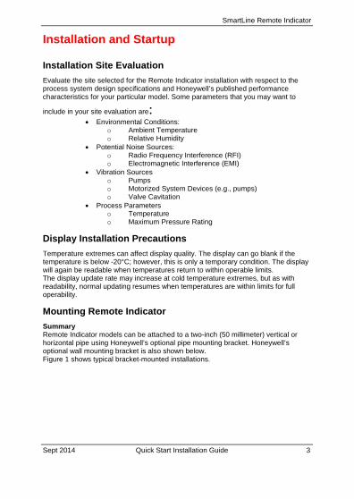
Summary Remote Indicator models can be attached to a two-inch (50 millimeter) vertical or horizontal pipe using Honeywell’s optional pipe mounting bracket. Honeywell’s optional wall mounting bracket is also shown below. Figure 1 shows typical bracket-mounted installations.
SmartLine Remote Indicator
4 Quick Start Installation Guide Sept 2014
Figure 1: Typical Bracket Mounted Installations
HORIZONTAL PIPE MOUNTING WALL MOUNTING
VERTICAL PIPE MOUNTING
SmartLine Remote Indicator
Sept 2014 Quick Start Installation Guide 5
Mounting Dimensions
Refer to Honeywell drawing number 50094836 for detailed electronic housing dimensions. Refer to Honeywell drawing numbers 50095917 for detailed pipe mounting dimensions and 50095918 for detailed wall mounting dimensions. Abbreviated overall dimensions are also shown on the Specification Sheets for the Remote Indicator models. This section assumes that the mounting dimensions have already been taken into account and the mounting area can accommodate the Remote Indicator.
Bracket Mounting Procedure
1. Align the two mounting holes in the Remote Indicator with the two slots in the mounting bracket and assemble the (2) M8 hex cap screws, (2) lockwashers and (2) flat washers provided. Rotate Remote Indicator assembly to the desired position and torque the M8 hex cap screws to 27,0 Nm/20,0 Lb-ft maximum.
Pipe Mount Option: Refer to Figure 2
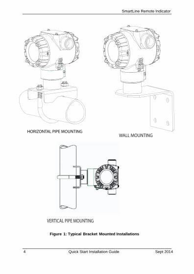
2. Position the bracket on a 2-inch (50.8 mm) horizontal or vertical pipe, and install a “U” bolt around the pipe and through the holes in the bracket. Secure the bracket with the nuts, flat washers and lock washers provided.
3. Wall Mount Option: Position the bracket on the mounting surface at the desired location and secure the bracket to the mounting surface using the appropriate hardware (Wall mounting hardware requirements to be determined and supplied by the end user)
4.
Figure 2: Pipe Mounting Bracket Secured to a Horizontal or Vertical Pipe
Horizontal PipeU - bolt U - bolt
Flat Washers, Lockwashers and Nuts
Flat Washers, Lockwashers
and Nuts
Vertical Pipe
SmartLine Remote Indicator
6 Quick Start Installation Guide Sept 2014
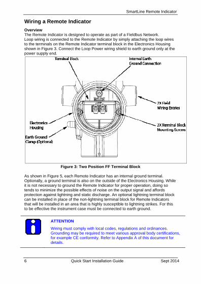
Wiring a Remote Indicator
Overview The Remote Indicator is designed to operate as part of a Fieldbus Network. Loop wiring is connected to the Remote Indicator by simply attaching the loop wires to the terminals on the Remote Indicator terminal block in the Electronics Housing shown in Figure 3. Connect the Loop Power wiring shield to earth ground only at the power supply end.
Figure 3: Two Position FF Terminal Block
As shown in Figure 5, each Remote Indicator has an internal ground terminal. Optionally, a ground terminal is also on the outside of the Electronics Housing. While it is not necessary to ground the Remote Indicator for proper operation, doing so tends to minimize the possible effects of noise on the output signal and affords protection against lightning and static discharge. An optional lightning terminal block can be installed in place of the non-lightning terminal block for Remote Indicators that will be installed in an area that is highly susceptible to lightning strikes. For this to be effective the instrument case must be connected to earth ground.
ATTENTION
Wiring must comply with local codes, regulations and ordinances. Grounding may be required to meet various approval body certifications, for example CE conformity. Refer to Appendix A of this document for details.
SmartLine Remote Indicator
Sept 2014 Quick Start Installation Guide 7
Wiring Procedure
1. See Figure 3, above, for parts locations. Loosen the end cap lock using a 1.5 mm Allen wrench.
2. Remove the end cap cover from the terminal block end of the Electronics Housing.
3. Feed loop power leads through one end of the conduit entrances on either side of the Electronics Housing. The Remote Indicator accepts up to 16 AWG wire.
4. Plug the unused conduit entrance with a conduit plug appropriate for the environment.
5. Feed both loop powered leads through the Ferrite core, 32301350-001, and then back around and through a second time.
6. Connect both loop power leads to the loop terminals. Torque terminal screws to 0,6 N.m (5.3 lbf.in) to 0.8 N.m (7.0 lbf.in). Note. The remote Indicator is not polarity-sensitive.
7. Replace the end cap and secure it in place being careful not to damage the ferrite core or wires.
Fieldbus Network Wiring
For Fieldbus network wiring concepts, see application notes such as Relcom Inc. Fieldbus Wiring Guide.
Lightning Protection
If your Remote Indicator includes the optional lightning protection, connect a wire from the Earth Ground Clamp (see Figure 3) to Earth Ground to make the protection effective. Use a size 8 AWG or (8.37mm2) bare or green covered wire for this connection.
Supply Voltage Limiting Requirements
If your Remote Indicator complies with the ATEX 4 directive for self-declared approval per 94/9EC, the power supply has to include a voltage-limiting device. Voltage must be limited such that it does not exceed 9 to 32 V DC. Consult the process design system documentation for specifics.
ATTENTION
FF power Supply along with the Terminators has to be used.
SmartLine Remote Indicator
8 Quick Start Installation Guide Sept 2014
Explosion-Proof Conduit Seal
WARNING
When installed as explosion proof in a Division 1 Hazardous Location, keep covers tight while the Remote Indicator is energized. Disconnect power to the Remote Indicator in the non-hazardous area prior to removing end caps for service.
When installed as non-incendive equipment in a Division 2 hazardous location, disconnect power to the Remote Indicator in the non-hazardous area, or determine that the location is non-hazardous before disconnecting or connecting the Remote Indicator wires.
Remote Indicator installed as explosion proof in Class I, Division 1, Group A Hazardous (classified) locations in accordance with ANSI/NFPA 70, the US National Electrical Code, with 1/2 inch conduit do not require an explosion-proof seal for installation. If 3/4 inch conduit is used, a LISTED explosion proof seal must be installed in the conduit, within 18 inches (457.2 mm) of the Remote Indicator.
SmartLine Remote Indicator
Sept 2014 Quick Start Installation Guide 9
WRITE PROTECT JUMPER ON FOUNDATION FIELDBUS (FF) On Foundation Fieldbus Remote Indicator there is no Failsafe jumper selection but there is a Write Protect jumper.
The bottom jumper sets the Write Protect. The default setting is OFF (Un-protected).
When set to the On (Protected) position, Changed configuration parameters cannot be written to the transmitter.
When set to the OFF (Un-protected) position, Changed configuration parameters can be written to the transmitter.
ATTENTION: Electrostatic Discharge (ESD) hazards. Observe precautions for handling electrostatic sensitive devices.
WARNING! PERSONAL INJURY: Risk of electrical shock. Disconnect power before proceeding. HAZARDOUS LIVE voltages greater than 30 Vrms, 42.4 Vpeak, or 60 VDC may be accessible. Failure to comply with these instructions could result in death or serious injury.
Step Action
1 Turn OFF Remote indicator power.
2 Loosen the end-cap lock, and unscrew the end cap from the Electronics side of the Transmitter housing.
3 If applicable, carefully depress the tabs on the sides of the Display Module and pull it off.
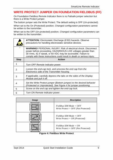
4 Set the Write Protect jumper (Bottom jumper) to the desired behavior (Protected or Unprotected). See Figure 4 for jumper positioning.
5 Screw on the end cap and tighten the end-cap lock.
6 Turn ON Remote Indicator power.
Image Description
Fieldbus SIM Mode = OFF Write Protect = OFF (Not Protected)
Fieldbus SIM Mode = OFF Write Protect = ON (Protected)
Fieldbus SIM Mode = ON Write Protect = OFF (Not Protected)
Figure 4: Fieldbus Write Protect
SmartLine Remote Indicator
10 Quick Start Installation Guide Sept 2014
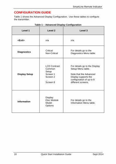
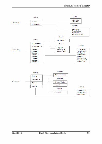
CONFIGURATION GUIDE Table 1 shows the Advanced Display Configuration. Use these tables to configure the transmitter.
Table 1 – Advanced Display Configuration
Level 1 Level 2 Level 3
<Exit> n/a n/a
Diagnostics Critical Non-Critical
For details go to the Diagnostics Menu table.
Display Setup
LCD Contrast Common Setup Screen 1 Screen 2 … Screen 8
For details go to the Display Setup Menu table. Note that the Advanced Display supports the configuration of up to 8 different screens.
Information
Display Elec Module Model Options
For details go to the Information Menu table.
SmartLine Remote Indicator
Sept 2014 Quick Start Installation Guide 11
SmartLine Remote Indicator
12 Quick Start Installation Guide Sept 2014
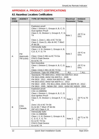
APPENDIX A. PRODUCT CERTIFICATIONS A3. Hazardous Locations Certifications
MSG CODE
AGENCY TYPE OF PROTECTION Electrical Parameter
Ambient Temp.
A FM Approvals TM (USA)
Explosion proof: Class I, Division 1, Groups A, B, C, D;Dust Ignition Proof: Class II, III, Division 1, Groups E, F, G; T4 Class 1, Zone 1, AEx d IIC T4 Gb Class 2, Zone 21, AEx tb IIIC T 95oC IP 66 Db
Note 1 -20 ºC to 70ºC
Intrinsically Safe: Class I, II, III, Division 1, Groups A, B, C,D, E, F, G; T4 Class I Zone 0 AEx ia IIC T4 Ga FISCO Field Device Ex ia IIC T4
Note 2 -20 ºC to 70ºC
Non-Incendive Class I, Division 2, Groups A, B, C, D; T4 Class I Zone 2 AEx nA IIC T4 Gc
Note 1 -20 ºC to 70ºC
Enclosure: Type 4X/ IP66/ IP67 ALL ALL Standards: FM 3600:2011; ANSI/ ISA 60079-0: 2013 FM 3615:2006; ANSI/ ISA 60079-1 : 2009 FM 3616 : 2011 ; ANSI/ ISA 60079-31 : 2009 FM 3610:2010; ANSI/ ISA 60079-11 : 2013 FM 3810 : 2005 ; FM 3611:2004; ANSI/ ISA 60079-15 : 2012 ; FM 3810 : 2005 ; NEMA 250 : 2003 ; ANSI/ IEC 60529 : 2004
B CSA-Canada
Explosion proof: CSA 14.2689056 Class I, Division 1, Groups A, B, C, D;Dust Ignition Proof: Class II, III, Division 1, Groups E, F, G; T4 Zone 1 Ex d IIC T4 Gb Ex tb IIIC T 95oC IP 66 Db DIP A21 Class II, III
Note 1 -20 ºC to 70 ºC
Intrinsically Safe: CSA 14.2689056 Class I, II, III, Division 1, Groups A, B, C, D, E, F, G; T4 Ex ia IIC T4 Ga FISCO Field Device Ex ia IIC T4
Note 2 -50 oC to 70 oC
SmartLine Remote Indicator
Sept 2014 Quick Start Installation Guide 13
MSG CODE
AGENCY TYPE OF PROTECTION Electrical Parameter
Ambient Temp.
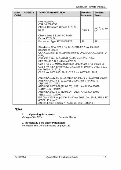
Non-Incendive CSA 14.2689056 Class I, Division 2, Groups A, B, C, D; T4 Class I Zone 2 Ex nA IIC T4 Gc Ex nA IIC T4 Gc
Note 1 -50 oC to 70 oC
Enclosure: Type 4X/ IP66/ IP67 ALL ALL
Standards: CSA C22.2 No. 0-10; CSA 22.2 No. 25-1966 (reaffirmed 2009); CSA C22.2 No. 30-M1986 (reaffirmed 2012); CSA C22.2 No. 94-M91; CSA C22.2 No. 142-M1987 (reaffirmed 2009); CSA-C22.2No.157-92 (reaffirmed 2012); C22.2 No. 213-M1987(reaffirmed 2012); C22.2 No. 60529-05 C22.2 No. CSA 60079-0:2011; C22.2 No. 60079-1: 2011; C22.2 No. 60079-11: 2011; C22.2 No. 60079-15: 2012; C22.2 No. 60079-31: 2012; ANSI/ ISA12.12.01-2012; ANSI/ ISA 60079-0 (12.00.01): 2009 ; ANSI/ ISA 60079-1 (12.22.01): 2009 ; ANSI/ ISA 60079-11(12.02.01) : 2012; ANSI/ ISA 60079-26 (12.00.03) : 2011; ANSI/ ISA 60079-15(12.12.02) : 2012 ; ANSI/ ISA 60079-27 (12.02.04) : 2006; ANSI/ ISA 60079-31(12.10.03) : 2009 ; FM Class 3615: Aug 2006; FM Class 3616: Dec 2011; ANSI/ IEC 60529 : Edition 2.1 ANSI/ UL 913: Edition 7; ANSI/ UL 916 : Edition 4 ;
Notes
1. Operating Parameters: Voltage= 9 to 32 V Current= 28 mA 2. Intrinsically Safe Entity Parameters For details see Control Drawing on page 131.
SmartLine Remote Indicator
14 Quick Start Installation Guide Sept 2014
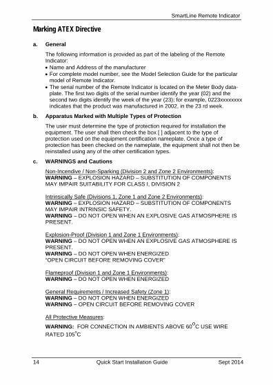
Marking ATEX Directive
a. General
The following information is provided as part of the labeling of the Remote Indicator: Name and Address of the manufacturer For complete model number, see the Model Selection Guide for the particular
model of Remote Indicator. The serial number of the Remote Indicator is located on the Meter Body data-
plate. The first two digits of the serial number identify the year (02) and the second two digits identify the week of the year (23); for example, 0223xxxxxxxx indicates that the product was manufactured in 2002, in the 23 rd week.
b. Apparatus Marked with Multiple Types of Protection
The user must determine the type of protection required for installation the equipment. The user shall then check the box [ ] adjacent to the type of protection used on the equipment certification nameplate. Once a type of protection has been checked on the nameplate, the equipment shall not then be reinstalled using any of the other certification types.
c. WARNINGS and Cautions
Non-Incendive / Non-Sparking (Division 2 and Zone 2 Environments): WARNING – EXPLOSION HAZARD – SUBSTITUTION OF COMPONENTS MAY IMPAIR SUITABILITY FOR CLASS I, DIVISION 2 Intrinsically Safe (Divisions 1, Zone 1 and Zone 2 Environments): WARNING – EXPLOSION HAZARD – SUBSTITUTION OF COMPONENTS MAY IMPAIR INTRINSIC SAFETY. WARNING – DO NOT OPEN WHEN AN EXPLOSIVE GAS ATMOSPHERE IS PRESENT. Explosion-Proof (Division 1 and Zone 1 Environments): WARNING – DO NOT OPEN WHEN AN EXPLOSIVE GAS ATMOSPHERE IS PRESENT. WARNING – DO NOT OPEN WHEN ENERGIZED “OPEN CIRCUIT BEFORE REMOVING COVER” Flameproof (Division 1 and Zone 1 Environments): WARNING – DO NOT OPEN WHEN ENERGIZED General Requirements / Increased Safety (Zone 1): WARNING – DO NOT OPEN WHEN ENERGIZED WARNING – OPEN CIRCUIT BEFORE REMOVING COVER All Protective Measures:
WARNING: FOR CONNECTION IN AMBIENTS ABOVE 60o
C USE WIRE
RATED 105oC
SmartLine Remote Indicator
Sept 2014 Quick Start Installation Guide 15
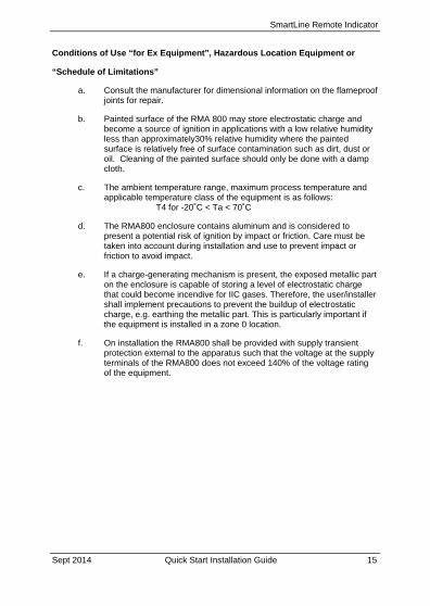
Conditions of Use “for Ex Equipment”, Hazardous Location Equipment or
“Schedule of Limitations”
a. Consult the manufacturer for dimensional information on the flameproof joints for repair.
b. Painted surface of the RMA 800 may store electrostatic charge and become a source of ignition in applications with a low relative humidity less than approximately30% relative humidity where the painted surface is relatively free of surface contamination such as dirt, dust or oil. Cleaning of the painted surface should only be done with a damp cloth.
c. The ambient temperature range, maximum process temperature and applicable temperature class of the equipment is as follows:
T4 for -20˚C < Ta < 70˚C
d. The RMA800 enclosure contains aluminum and is considered to present a potential risk of ignition by impact or friction. Care must be taken into account during installation and use to prevent impact or friction to avoid impact.
e. If a charge-generating mechanism is present, the exposed metallic part on the enclosure is capable of storing a level of electrostatic charge that could become incendive for IIC gases. Therefore, the user/installer shall implement precautions to prevent the buildup of electrostatic charge, e.g. earthing the metallic part. This is particularly important if the equipment is installed in a zone 0 location.
f. On installation the RMA800 shall be provided with supply transient protection external to the apparatus such that the voltage at the supply terminals of the RMA800 does not exceed 140% of the voltage rating of the equipment.
SmartLine Remote Indicator
16 Quick Start Installation Guide Sept 2014
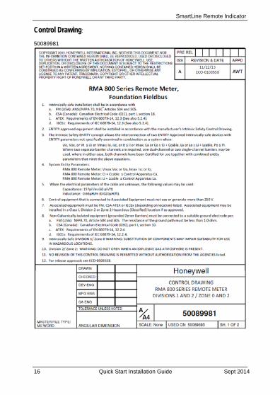
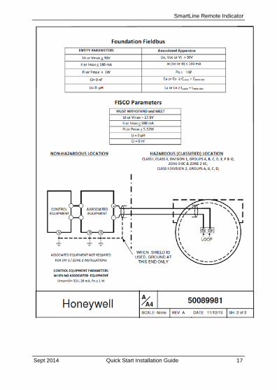
Control Drawing:
50089981
SmartLine Remote Indicator
Sept 2014 Quick Start Installation Guide 17
SmartLine Remote Indicator
Honeywell Process Solutions 1250 W Sam Houston Pkwy S 34-ST-25-52 Rev.2 Houston, TX 77042 September 2014 www.honeywellprocess.com 2014 Honeywell International Inc.
Sales and Service
For application assistance, current specifications, pricing, or name of the nearest Authorized Distributor, contact one of the offices below. ASIA PACIFIC (TAC) Australia Honeywell Limited, Phone: +(61) 7-3846 1255, FAX: +(61) 7-3840 6481 Toll Free 1300-36-39-36, Toll Free Fax: 1300-36-04-70 China – PRC – Shanghai, Honeywell China Inc. Phone: (86-21) 5257-4568, Fax: (86-21) 6237-2826 Singapore, Honeywell Pte Ltd. Phone: +(65) 6580 3278. Fax: +(65) 6445-3033 South Korea, Honeywell Korea Co Ltd. Phone:+(822)799 6114. Fax:+(822) 792 9015EMEA, Phone: + 80012026455 or +44 (0)1202645583. FAX: +44 (0) 1344 655554 Email: (Sales) [email protected] or (TAC) [email protected] NORTH AMERICA, Honeywell Process Solutions, Phone: 1-800-423-9883, Or 1-800-343-0228. Email: (Sales) [email protected] or (TAC) [email protected] SOUTH AMERICA, Honeywell do Brazil & Cia. Phone: +(55-11) 7266-1900. FAX: +(55-11) 7266-1905. Email: (Sales) [email protected] or (TAC) [email protected]
WARRANTY/REMEDY
Honeywell warrants goods of its manufacture as being free of defective materials and faulty workmanship. Contact your local sales office for warranty information. If warranted goods are returned to Honeywell during the period of coverage, Honeywell will repair or replace without charge those items it finds defective. The foregoing is Buyer's sole remedy and is in lieu of all other warranties, expressed or implied, including those of merchantability and fitness for a particular purpose. Specifications may change without notice. The information we supply is believed to be accurate and reliable as of this printing. However, we assume no responsibility for its use.
While we provide application assistance personally, through our literature and the Honeywell web site, it is up to the customer to determine the suitability of the product in the application.


![Profibus PA Fieldbus Display [ Revision 2 ] and Fieldbus ... Instruments... · Profibus PA Fieldbus Display [ Revision 2 ] and Fieldbus Indicator Fieldbus Interface Guide. ... Siemens](https://img.pdfslide.us/doc/110x75/5b2fe38e7f8b9ae16e8da83d/profibus-pa-fieldbus-display-revision-2-and-fieldbus-instruments.jpg)