Embed Size (px)
Citation preview

Honeywell Process Solutions
SmartLine SCT Configuration Toolkit
Installation & Start-up Guide
Doc No.: 34-ST-10-08 Revision 16
August 2020

SCT 3000 SmartLine Configuration Toolkit
SCT Configuration Toolkit Revision 16 ii
Notices and Trademarks
Copyright 2020 by Honeywell Inc. Revision 16, August 2020
While this information is presented in good faith and believed to be accurate, Honeywell disclaims the implied warranties of merchantability and fitness for a particular purpose and makes no express warranties except as may be stated in its written agreement with and for its customers.
In no event is Honeywell liable to anyone for any indirect, special or consequential damages. The information and specifications in this document are subject to change without notice.
Honeywell is a U.S. registered trademark.
Other brand or product names are trademarks of their respective owners.
Honeywell Process Solutions
1860 West Rose Garden Lane
Phoenix, Arizona 85027

SCT 3000 SmartLine Configuration Toolkit
Revision 16 SCT Configuration Toolkit iii
About This Document Abstract
This document describes how to use SmartLine Configuration Toolkit (SCT), which consists of application software and hardware installation.
Revision Notes Date Notes
August 2020 Firmware updates
August 2016 Updated for Windows 10
December 2015 SMV800 added
April 2014 Updated for SmartLine Temperature Transmitter release
July 2013 HART/DE Modem changed to DE Modem
December 2012 Updated for SmartLine Pressure Transmitter release
April 2012 Updated for ST800 Pressure Transmitter release
March 10 Updated for Windows 7
References − Documents that may be sources of reference for material discussed in this publication.
Document Title Doc ID SCT3000 Configuration Tool, for Bluetooth manual 34-CT-25-02
SMV800 SmartLine Multivariable Transmitter 34-SM-25-03
ST 800 Smart Pressure Transmitter User Manual 34-ST-25-35
ST700 Smart Pressure Transmitter User Manual 34-ST-25-44
SMV3000 Smart Multivariable Transmitter User’s Manual 34-SM-25-02
ST 3000 Smart Transmitter Release 300 User’s Manual 34-ST-25-14
STT 3000 Version 350 User’s Manual 34-ST-25-12
STT 3000 Series STT250 Operator Manual EN1I-6190
STT 3000 Series STT150 Operator Manual EN1I-6248
MagneW 3000 Electromagnetic Flowmeter User’s Manual 36-KI-25-01
MagneW 3000 PLUS Electromagnetic Flowmeter 36-KI-25-02

SCT 3000 SmartLine Configuration Toolkit
SCT Configuration Toolkit Revision 16 iv
Support and Contact Information
For Europe, Asia Pacific, North and South America contact details, see back page or refer to the appropriate Honeywell Solution Support web site:
Honeywell Process Solutions www.honeywellprocess.com
SCT3000 Configuration Toolkit https://www.honeywellprocess.com/sct-3000-smartline-configuration-toolkit.aspx
Training Classes http://www.honeywellprocess.com/en-US/training
Telephone and Email Contacts
Area Organization Phone Number
United States and Canada Honeywell Inc.
1-800-343-0228 Customer Service
1-800-423-9883 Global Technical Support
Global Email Support
Honeywell Process Solutions
Sales: [email protected] TAC: [email protected]

SCT 3000 SmartLine Configuration Toolkit
Revision 16 SCT Configuration Toolkit v
Symbol Definitions The following table lists those symbols used in this document to denote certain conditions.
Symbol Definition
CAUTION: Indicates a potentially hazardous situation which, if not avoided, may result in minor or moderate injury. It may also be used to alert against unsafe practices.
CAUTION symbol on the equipment refers the user to the product manual for additional information. The symbol appears next to required information in the manual.
WARNING: Indicates a potentially hazardous situation, which, if not avoided, could result in serious injury or death.
WARNING symbol on the equipment refers the user to the product manual for additional information. The symbol appears next to required information in the manual.
WARNING, Risk of electrical shock: Potential shock hazard where HAZARDOUS LIVE voltages greater than 30 Vrms, 42.4 Vpeak, or 60 VDC may be accessible.
ESD HAZARD: Danger of an electro-static discharge to which equipment may be sensitive. Observe precautions for handling electrostatic sensitive devices.
Protective Earth (PE) terminal: Provided for connection of the protective earth (green or green/yellow) supply system conductor.
Functional earth terminal: Used for non-safety purposes such as noise immunity improvement. NOTE: This connection shall be bonded to Protective Earth at the source of supply in accordance with national local electrical code requirements.
Earth Ground: Functional earth connection. NOTE: This connection shall be bonded to Protective Earth at the source of supply in accordance with national and local electrical code requirements.
Chassis Ground: Identifies a connection to the chassis or frame of the equipment shall be bonded to Protective Earth at the source of supply in accordance with national and local electrical code requirements.

SCT 3000 SmartLine Configuration Toolkit
SCT Configuration Toolkit Revision 16 vi
Contents
SmartLine SCT Configuration Toolkit ...................................................................................... i
Installation & Start-up Guide .................................................................................................. i Support and Contact Information .......................................................................................................... iv
1— Introduction ............................................................................................................ 1 SmartLine Configuration Toolkit ............................................................................................................. 1 Field Devices Supported ........................................................................................................................ 3 SCT 3000 Features ................................................................................................................................ 4 National Language Support .................................................................................................................... 5
2— System Requirements ........................................................................................... 6 Before You Begin ................................................................................................................................... 6 Computer Requirements ........................................................................................................................ 6 Software Compatibility ............................................................................................................................ 7 SCT Hardware ........................................................................................................................................ 7
3 - Software Installation .............................................................................................. 10 SCT 3000 Installation ........................................................................................................................... 10 SCT 3000 Software Application and Setup .......................................................................................... 10 CD ROM Installation ............................................................................................................................. 11
4— Hardware Installation ........................................................................................... 13 SCT Hardware ...................................................................................................................................... 13 HART/DE Bluetooth Modem ................................................................................................................ 13 HART/DE Modem hardware assembly and installation ....................................................................... 14 Serial Hardware Interface (for use with STT 150 only) ........................................................................ 17
5— Start up and Working Online ................................................................................ 19 SCT 3000 Application ........................................................................................................................... 19 Getting Online Quickly .......................................................................................................................... 19 SCT 3000 Features .............................................................................................................................. 25
6— Working Offline .................................................................................................... 27 Using the SCT 3000 Offline .................................................................................................................. 27
7—Using the SCT3000 Tool to Configure Local Display Screens on SMV800 .......... 31

SCT 3000 SmartLine Configuration Toolkit
Revision 16 SCT Configuration Toolkit vii
8— Online Help .......................................................................................................... 38 Online Help Features ........................................................................................................................... 38
9—Some Vista, Windows 7 and Windows 10 Tips and Notes: ................................... 39
10— Troubleshooting ................................................................................................. 42 Overview .............................................................................................................................................. 42 Troubleshooting SCT Application and the hardware ........................................................................... 42 SCT Error Codes .................................................................................................................................. 45 Status Bar ............................................................................................................................................ 47 Modem Maintenance ............................................................................................................................ 48
Appendix .................................................................................................................... 50
Glossary ..................................................................................................................... 51
SCT 3000 SmartLine Configuration Toolkit
SCT Configuration Toolkit Revision 16 viii
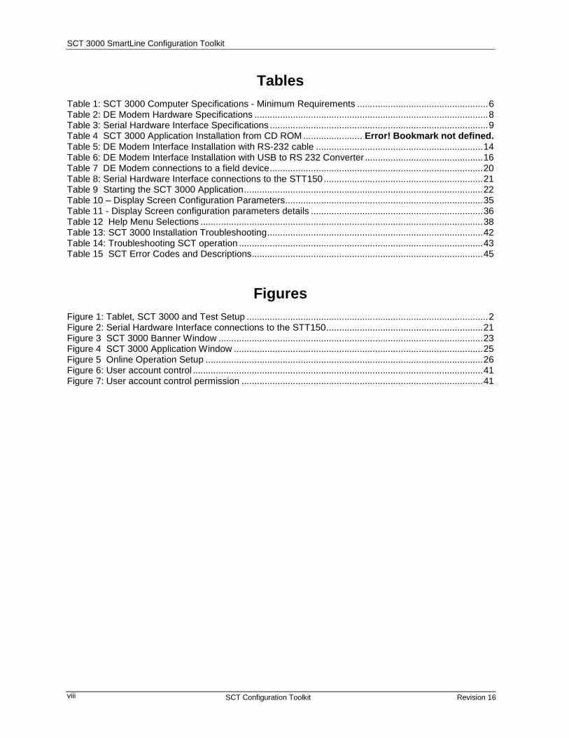
Tables Table 1: SCT 3000 Computer Specifications - Minimum Requirements ................................................... 6 Table 2: DE Modem Hardware Specifications ........................................................................................... 8 Table 3: Serial Hardware Interface Specifications ..................................................................................... 9 Table 4 SCT 3000 Application Installation from CD ROM ....................... Error! Bookmark not defined. Table 5: DE Modem Interface Installation with RS-232 cable ................................................................. 14 Table 6: DE Modem Interface Installation with USB to RS 232 Converter .............................................. 16 Table 7 DE Modem connections to a field device ................................................................................... 20 Table 8: Serial Hardware Interface connections to the STT150 .............................................................. 21 Table 9 Starting the SCT 3000 Application ............................................................................................. 22 Table 10 – Display Screen Configuration Parameters ............................................................................. 35 Table 11 - Display Screen configuration parameters details ................................................................... 36 Table 12 Help Menu Selections .............................................................................................................. 38 Table 13: SCT 3000 Installation Troubleshooting .................................................................................... 42 Table 14: Troubleshooting SCT operation ............................................................................................... 43 Table 15 SCT Error Codes and Descriptions.......................................................................................... 45
Figures Figure 1: Tablet, SCT 3000 and Test Setup .............................................................................................. 2 Figure 2: Serial Hardware Interface connections to the STT150 ............................................................. 21 Figure 3 SCT 3000 Banner Window ....................................................................................................... 23 Figure 4 SCT 3000 Application Window ................................................................................................. 25 Figure 5 Online Operation Setup ............................................................................................................ 26 Figure 6: User account control ................................................................................................................. 41 Figure 7: User account control permission .............................................................................................. 41

1— Introduction - SmartLine Configuration Toolkit
Revision 16 SCT Configuration Toolkit 1
1— Introduction
SmartLine Configuration Toolkit Honeywell’s SmartLine Configuration Toolkit, SCT 3000 provides a cost-effective and efficient means to configure, calibrate, diagnose and monitor Honeywell’s Smart field devices. The SCT 3000 is an engineering and maintenance software application designed for ease-of-use and increased productivity. The SCT 3000 runs on a Windows™-based personal computer, Laptop and Windows 10 Tablet specifically to support Honeywell’s Analog and Digitally Enhanced (DE) protocols in nonhostile, general-purpose field environments.
NOTE: DE Modem is a HART/DE modem as it has the interface built in to support both DE and HART Host applications; However, SCT 3000 application supports only DE devices and it uses DE interface part of the modem.
Software 1. SCT 3000 software
o Version 6.18.445 for Windows 7 and Windows 10 Operating Systems with RS232 HART/DE modem
o Version 7.22.373 and above supports communication with DE devices using Bluetooth HART/DE modem or RS232 HART/DE modem. Note that the PC / Laptop / Tablet should have Bluetooth support to be able to use the Bluetooth HART/DE modem.
Note: For PCs that do not have Bluetooth support, USB to Bluetooth 2.1 Adapter can be used. Recommended adapter is StartTech.com Mini USB Bluetooth 2.1 Adapter - Class 1 EDR Wireless Network Adapter (https://www.startech.com/Networking-IO/Bluetooth-Telecom/Mini-USB-Bluetooth-2-1-Adapter-Class-1-EDR~USBBT1EDR2).
For using SCT 3000 tool with a PC, Laptop or Tablet with Bluetooth support and HART/DE Bluetooth modem please refer the document see SCT 3000 documents listed in References.
.
2. Hardware
o HART/DE Bluetooth Modem, Adapter cables (1 with alligator clips; 1 with easy hooks)
1— Introduction - SmartLine Configuration Toolkit
2 SCT Configuration Toolkit Revision 16
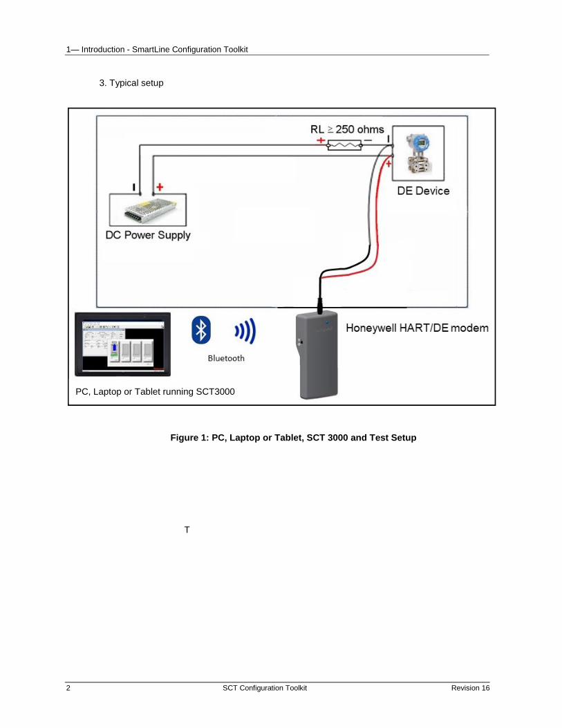
3. Typical setup
Figure 1: PC, Laptop or Tablet, SCT 3000 and Test Setup
T
PC, Laptop or Tablet running SCT3000
1— Introduction - Field Devices Supported
Revision 16 SCT Configuration Toolkit 3
Field Devices Supported The SCT 3000 operates and communicates with the following Honeywell SmartLine field devices:
1. ST 3000 Smart Pressure Transmitter *
2. ST 3000 Smart Pressure Transmitter with integral meter
3. SmartLine Pressure Transmitters (ST 800, ST 700)
4. STT 3000 Smart Temperature Transmitter, (includes Series STT150, STT250 and
STT350 tranmsitters)
5. STT850 SmartLine Temperature Transmitter
6. SMV 3000 SmartLine Multivariable Transmitter
7. SMV800 SmartLine Multivariable Transmitter **
8. MagneW Plus
* Note: that the SCT 3000 will not communicate with older ST 3000 transmitters that are analog only
and contain software version 2.2 or earlier, or version 6.1 or earlier.
** Note: SMV800 transmitter is supported only on SCT version 6.18.445 and above under
Windows 7 and Windows 10”
The SCT 3000 Online User Manual provides useful configuration and diagnostic information for the supported field devices. More detailed information for configuring and operating these field devices is found in separate user manual and operating guide documents that support each field device. See References on Page iii in the front of this document for a list of these documents.

1— Introduction - SCT 3000 Features
4 SCT Configuration Toolkit Revision 16
SCT 3000 Features The SmartLine Configuration Toolkit has all the following features:
1. Windows-based software application allows easy access to all SmartLine configuration and calibration device parameters.
2. Online and Offline Mode operation
• Offline mode allows you to configure and save database files for various devices without being connected to the device.
• In the online mode you can download the saved databases to the devices and perform online functions such as:
− Selection of the Communications Mode (Honeywell DE or analog)
− Configuration and device diagnosis
− Calibration
− Display of device parameters
− Device check out
3. Built-in Database Templates
• Default database templates are provided for each type of field device to simplify and reduce implementation time and effort.
• Database Verification
• Database parameters are checked for “reasonable” values automatically to help avoid mistakes.
• A database compare function detects differences between the device database and the SCT database providing assurance of proper installation.
4. PV Monitoring
• Graphical representations of device inputs and outputs are shown in a window so you can monitor the operating status of SmartLine field devices.
• Window shows you values of input PVs, output PVs and SVs of the connected device in real time.

1— Introduction - Language Support
Revision 16 SCT Configuration Toolkit 5
5. Flow Wizard
• A built-in wizard that provides considerable time savings and ease of use for you when configuring the flow process variable in a SmartLine Multivariable Transmitter. By providing responses to configuration questions and choices in a step-by-step progression, you can configure the flow variable (PV4). Upon completion, a configuration solution is generated by the wizard that can be saved as a database file and downloaded to the field device.
Windows operating system references Before you begin to use the SCT 3000 know how to perform basic operations with your computer and with Windows. The information and procedures presented in this manual assume you are already familiar with Windows. If necessary, you may find it useful to review the following reference manuals from Microsoft before proceeding:
1. Getting Started with Microsoft Windows - a guide to setting up Windows on your system and a brief introduction to Windows.
2. Microsoft Windows User’s Guide - provides a comprehensive description of Windows; includes explanations and procedures for first-time users, in addition to topics for advanced users.
3. Microsoft Windows Tutorial - provides online instructions for using a mouse and for performing some basic tasks in Windows.
Language Support The SCT 3000 now provides language support for English, French, Spanish, Italian, and German. The language support feature will display the SCT application window, the associated tab cards and parameter field labels in the selected language. During installation, the SCT 3000 setup program identifies the regional settings of the computer and automatically selects the appropriate language support. If the regional settings are not one of the supported languages, then English is installed as the default language. Please note that the online Help and online User Manual will still be displayed in English.

6 SCT Configuration Toolkit Revision 16
2— System Requirements
Before You Begin Before you install the SCT on your computer and start using it, there are a number of system requirements for the computer you will be using that will ensure trouble-free installation and operation with the SCT 3000 application.
Computer Requirements The SCT 3000 software application runs on a variety of commercially-available portable or desktop computer platforms that may also be shared with other applications. Table 1 lists the system capabilities needed to install and operate the SCT 3000 application.
Table 1: SCT 3000 Computer Specifications - Minimum Requirements
PC Specification Computer: Laptop or Desktop PC or Windows 10 Tablet with Bluetooth3
CPU Pentium 90 MHz or better
Display SVGA (Monochrome or Color)
Operating System Windows 71 or Windows 10 (Tablet needs Windows 10 version with Bluetooth support)
Pointing Device Mouse or trackball-compatible device
RAM Minimum 16 MB (32 MB recommended).
Application Size 12 MB (application) + 5 kB per database file
Application / file transfer
Portable media/peripheral interface (eg. USB) are required for:
• installation of SCT 3000 software and updates
• configuration database import and export
Ports Parallel: Printer (not supported in the Tablet).
Serial: For STT150 support. See Note 2
USB Port: For STT150 support. See Note 3
Bluetooth3: For all DE devices, other than STT150 device
Note that the SCT 3000 software version 7.22.373 will support existing DE modems in the field in addition to the new Bluetooth modem
1. The software will work on stated operating systems but the support is available only for current Microsoft supported
systems.
2. To use the SCT 3000 on a PC or Laptop computer without serial port, you must install USB to RS-232 Converter Driver
Software. See the Installation Instructions sheet (34-ST-33-61). This is applicable to existing DE modems in the field
only. New Bluetooth modem does not require any drivers.
3. For laptops and PCs not having native Bluetooth support refer to SCT3000 Configuration for Bluetooth HART/DE
manual 34-CT-03-02.pdf for a USB to Bluetooth adapter to enable the function.

2— System Requirements - Software Compatibility
Revision 16 SCT Configuration Toolkit 7
Computer Models for use with SCT 3000 The Dell models with the following Operating Systems have been performance-qualified by Honeywell for use with the SmartLine Configuration Toolkit.
• Windows 7
• Windows 10
Refer to compatibility of the SCT 3000 software and the modem hardware in section 1— Introduction
Software Compatibility The SCT 3000 may coexist with the following application programs on a computer.
1. Microsoft Office Tools.
The import/export capabilities of SCT database files allow for only “tab” delimited text files.
Refer to Appendix B in this document for further information on software compatibility.
SCT Hardware Communication between a computer running the SCT 3000 application and the field device is accomplished through one of two hardware interfaces:
1. The HART/DE Bluetooth Modem or RS 232 HART/DE modem communicates to all Honeywell field devices supported by the SCT 3000, (except the STT 150). See Table 2 for specifications.
2. A Serial Hardware Interface is used only when communicating to the STT 150 smart temperature transmitter. See Table 3 for specifications.
Each of these hardware interfaces is described in Section 4, Hardware Installation.
Environmental specifications for SCT hardware The SCT is designed to operate in a non-hostile, general purpose field environment. It is important to operate the SCT in an environment that is within the ranges for temperature, humidity, shock and vibration that are specified in Table 2 and Table 3.
WARNING The SCT 3000 is not certified for use in hazardous locations.

8 SCT Configuration Toolkit Revision 16
Table 2: DE Modem Hardware Specifications
Specification Description
Communication Protocol Compatible with Honeywell Smart Field Network (SFN). Temperature Range
Operating Storage
-10°C to 50°C -20°C to 60°C
Operating Humidity Range (RH)
10-90%
Shock Range Operating
Storage Range
5 G, 50ms 15 G, 11ms
Vibration Range Operating
Storage Range
0.2 G (0-100 Hz, 0.75 mmP-P 0.5 G (0-100 Hz, 0.75 mmP-P)
Weight 0.45lbs (approx)
Approval Bodies EUROPE
EU Declaration : EMC Directive (2014/30/EU)
Radio Equipment Directive (2014/ 53/ EU) RoHS Directive (2011/ 65/ EU)
Modem bluetooth specifications
FCC ID : T9JRN41-3
IC ID :6514A-RN413 Country Certification
Approval and ID Test Standard
USA FCC T9J-RN41-1* FCC Part 15 Subpart B : 2008 Class B FCC CRT Title 47 Part 15 Subpart C
EU CE* ETSI EN 301 489-1 V1.8.1 ETSI EN 301 489-17 V2.1.1 ETSI EN 300 328-1 V1.7.1 EN 55022 Class B radiated EN61000-4-2 ESD imunity EN61000-4-3 radiated field EN61000-4-6 RF imunity EN61000-4-7 power magnetic imunity EN 60950-1 :2001+A11 :2004
Canada IC: 6514A-RN42* IC RSS-210 low power comm. device Korea KC* Certifucation in progress Worldwide BQB :B013180** SPP and DUN profiles
* Regulatory (Country / Government) approvals
** Bluetooth SIG Approvals
Certificates Bluetooth CCAT
RN41 QDID is 82009
HART/DE Basic Modem DI: D050508

2— System Requirements - SCT Hardware
Revision 16 SCT Configuration Toolkit 9
Table 3: Serial Hardware Interface Specifications
Specification Description
Communication Protocol
Computer interface
Field device inteface
Compatible with RS232 Protocol
Compatible with 5Vdc level or 3Vdc level
Baudrate 19200 bps, maximum
9600 bps, typical
Temperature Range
Operating
Storage
0°C to +50°C (32°F to +122°F), ambient
-40°C to +85°C (-40°F to +185°F), ambient
Operating Humidity Range (RH) 10-90%, noncondensing
Electrical Isolation 250 Vac
Cable length
Computer interface (RS232)
Field device interface
10 meters, maximum
3 meters, maximum
Weight (Interface module + cable) 0.5 lbs., maximum
Approval Bodies Mark CE

10 SCT Configuration Toolkit Revision 16
3 - Software Installation
SCT 3000 Installation Installation of the SCT 3000 is broken down into two separate procedures:
1. Software installation
2. Hardware assembly and installation, (described in Section 4).
Note: Install the software first, before the hardware.
Note: For Installation and setup of of SCT 3000 software and HART/DE Bluetooth modem. See References (SCT3000 Configuration Tool Blutooth manual, 34-CT-25-02)
SCT 3000 Software Application and Setup The SCT 3000 software application and Installation Utility are available on a CD ROM. Follow the procedure in this section to install the software
Running the installation utility The SCT 3000 software application is installed on your computer using the installation utility. The utility creates all necessary directories, files, application groups and/or items to run SCT application. The utility also updates the registry and checks for adequate system resources, such as disk space and Windows version number.
The installation utility provides a step-by-step procedure for installing the SCT 3000 application on your computer. You must follow the procedure and the appropriate prompts in the utility to properly install the application. You cannot simply copy the files from the CD to your hard drive.
It is recommended that you close any other applications you have running in Windows as these can greatly increase the time for installing your SCT 3000 application.
3 - Software Installation - CD ROM Installation
Revision 16 SCT Configuration Toolkit 11
CD ROM Installation
SCT 3000 software version 7.22.373 and above will not support CD ROM installation.
Software can be downloaded here: SCT3000 Software (7.22.373)
Uninstall Before installing the new version of the software, uninstall any previous versions of the SCT 3000 product.
Windows 7 and Windows 10: Select Start/Control Panel/Programs/Uninstall a program/SCT3000/Uninstall
Follow the dialog prompts to completely uninstall the product.
Install NOTE Make sure that you have “Administrator” priveledges before installing the product.
For Installation and setup of of SCT 3000 software and HART/DE Bluetooth modem. See References (SCT3000 Configuration Tool Blutooth manual, 34-CT-25-02)
Legacy installation with RS 232 HART/DE modedm
SCT 3000 software version 7.22.373 and above will not support CD ROM installation.
Software can be downloaded here: SCT3000 Software (7.22.373)
fter installing SCT 3000 software, go to Section 4 – Hardware Installation to assemble and install the SCT 3000 hardware.
.

12 SCT Configuration Toolkit Revision 16
This page has been intentionally left blank

SCT Hardware
Revision 16 SCT Configuration Toolkit 13
4— Hardware Installation
SCT Hardware As part of the SCT 3000 installation, you must assemble the hardware interface components and then connect them to the computer that you will use with the SCT software application. There are two hardware interfaces available for use with the SCT:
1. HART/DE Modem described below
2. Serial hardware interface (for use with STT 150 only) which is described on page 17.
Note: Install the software first, before the hardware.
HART/DE Bluetooth Modem HART/DE Bluetooth Modem is used to connect and communicate with all SmartLine field devices supported by the SCT 3000, except for the STT 150 transmitter. Components are illustrated below.
1. Option 1: HART/DE Bluetooth modem connected to PC/Laptop or Tablet over the Bluetooth
Note: That SCT3000 version 7.22.122 and above works with RS232 or Bluetooth modem.
For Installation and setup of of SCT 3000 software and HART/DE Bluetooth modem. See References (SCT3000 Configuration Tool Blutooth manual, 34-CT-25-02)
2. Option 2: Modem is connected to the PC via DB9 Male to DB9 Female 9C Serial Pass-Through Cable (for existing modems in the field)
3. Option 3: Modem is connected to the PC via USB to RS 232 converter adapter (for existing modems in the field)
The adapter cable is used to connect the modem to the field device. The SCT is shipped with two adapter cables. One adapter cable is equipped with easy hooks and the other has alligator clips at the field device end of the cable.
These options are described below.

14 SCT Configuration Toolkit Revision 16
HART/DE Modem hardware assembly and installation To use the SCT 3000 on a desktop computer without a RS-232 Serial Port, you must install a USB to RS-232 Converter and driver. You will be able to order this part from Honeywell. Please see your Honeywell sale representative for more information.
Option 2: DE Modem Interface Installation with RS-232 cable
Note: The DE Modem interface is used with the SCT 3000 when communicating with the non-STT 150 transmitters
Table 4: DE Modem Interface Installation with RS-232 cable
Step Action
1 Insert the 9-pin D-type connector of the RS-232 cable into an available serial port connector on the computer and secure using the two captive mounting screws. See above figure.
2 The COM port also must be set in the SCT 3000 application. See Set COM Port on page 18.
3 Connect the other end of the RS-232 cable to the Modem. See Communication Port and Advanced Settings on page 15.
4 Go to DE Modem connections to a field device (page 20) for a procedure on how to connect the assembled SCT 3000 hardware between the computer and the transmitter.

HART/DE Modem hardware assembly and installation
Revision 16 SCT Configuration Toolkit 15
Communication Port and Advanced Settings Windows 7 and Windows 10 select Start/Control Panel/System and Maintenance/System/Device Manager/ Ports (COM & LPT) / Communications Port
Right click on Communications Port and select Properties. Select Port Settings.
Make sure the settings are as below.
Select Advanced and make sure that the Use FIFO buffers (…) check box is selected and Receive Buffer and Transmit Buffers are set to High. See following figure.
Option 3: DE Modem Interface Installation with USB to RS 232 Converter

16 SCT Configuration Toolkit Revision 16
The DE Modem interface is used with the SCT 3000 when communicating with the non-STT 150 transmitters
Table 5: DE Modem Interface Installation with USB to RS 232 Converter
Step Action
1 Install the USB to RS 232 Converter as in the Instruction sheet 34-ST-33-61.
2 Connect the Detachable Extension cable (part of the USB to RS 232 converter package) to an available USB port on the computer for SCT 3000 use. The COM port also must be set in the SCT 3000 application. See Set COM Port on page 18.
3 Connect the other end of the extension cable to the Converter
4 Connect the DB9 connector end of the Converter to the DB9 connector on the Modem.
5 Securely fasten the stereo phone jack connector end of the Adapter Cable into the terminal on the other end of the Modem.
6 Go to DE Modem connections to a field device (page 20) for a procedure on how to connect the assembled SCT 3000 hardware between the computer and the transmitter.

Serial Hardware Interface (for use with STT 150 only)
Revision 16 SCT Configuration Toolkit 17
Serial Hardware Interface (for use with STT 150 only) A serial hardware interface is available to use with the SCT 3000 when communicating with the STT 150 Smart Temperature Transmitter. The interface consists of the following components:
1. Serial Interface Module which is an RS-232 standard hardware interface (9-pin D-type connector) that provides the physical and electrical interface between the computer and the field device.
2. An Interface cable connects the serial interface module to the field device. The cable features a 4-pin connector for the interface module connection and a 3-pin connector at the field device end.
Note: The serial hardware interface is used with the SCT 3000 when communicating with the STT 150 Smart Temperature Transmitter. See Option 2: USB-to-RS-232 converter for USB Option
Option 1: Interface cable
Step Action
1 Ensure that the power to the computer (PC) is off.
2 Insert the 9-pin D-type connector of the serial interface module into an available serial port connector on the computer and secure using the two captive mounting screws. See figure below.
3 Connect the interface module to an available serial port (COM 1 or 2) on the computer for SCT 3000 use. The COM port also must be set in the SCT 3000 application. See Set COM Port on page 18.
4 Insert the interface cable end (4-pin) into the 4-pin connector on the serial interface module.
5 Go to Serial Hardware Interface connections to the STT150 for a procedure on how to connect the assembled SCT 3000 hardware between the computer and the STT150 transmitter.

18 SCT Configuration Toolkit Revision 16
Option 2: USB-to-RS-232 converter There is also USB 2.0 to RS-232 Converter option available for computers that do not have a RS-232 Serial Port. After installing it you must install the driver.
Step Action
1 Install the USB to RS 232 Converter as in the Instruction sheet 34-ST-33-61.
2 Connect the Detachable Extension cable (that is part of the USB to RS 232 Converter package) to an available USB port on the computer for SCT 3000 use. The COM port also must be set in the SCT 3000 application. See Set COM Port on page 18.
3 Connect the other end of the extension cable to the Converter
4 Connect the DB9 connector end of the Converter to the DB9 connector on the Modem.
5 Securely fasten the stereo phone jack connector end of the Adapter Cable into the terminal on the other end of the Modem.
6 Go to Serial Hardware Interface connections to the STT150 for a procedure on how to connect the assembled SCT 3000 hardware between the computer and the transmitter.
Set COM Port (DE Modem Interface or Serial Hardware Interface) In the View menu:
Select Options… and then select the General tab.
At the bottom of the tab is the Serial Port box.
Select the name of the serial port that the computer is using for SCT communications (default COM 1). You can type in a name if none of the choices match the name of the computer serial port.
Click OK to make selection and close the Options window.

SCT 3000 Application
Revision 16 SCT Configuration Toolkit 19
5— Start up and Working Online
SCT 3000 Application The SCT 3000 application is an easy-to-use graphical user interface that is similar in functionality to any other Windows-based application. Start up procedures consist of connecting the SCT hardware to a field device and establishing online communications with the devce. Also this section describes the SCT 3000 application window, its various components, and how to access the menus and commands to gain more insight into the SCT features.
Getting Online Quickly The following procedures tell you how to:
Connect the SCT 3000 hardware to a field device. For help with the connection see References (SCT3000 Configuration Tool Blutooth manual, 34-CT-25-02)
• Make an online connection to commnicate with a field device.
• Perform online tasks, such as view device parameters, check device status and perform online configuration or device calibration.
Connecting to a field device
WARNING RS232 HART/dE modem is not certified for use in hazardous locations.
HART/DE Bluetooth modem is certified with Class1, Div2
ATTENTION The SCT 3000 can be connected to only one Smart field device at a time.
Perform the procedure in Table 5 to connect the assembled SCT 3000 hardware between the computer and the SmartLine field device.

20 SCT Configuration Toolkit Revision 16
Table 6 DE Modem connections to a field device Step Action
1 The SCT hardware must be assembled and installed according to the procedures in DE Modem hardware assembly and installation on page 14.
2 Connect the easy hooks or alligator clips on the end of the adapter cable to the respective terminals on the Smart field device or field terminals as shown below: -- connect the red lead to the positive terminal. -- connect the black lead to the negative terminal.
3 Go to Starting the SCT 3000 application on page 22.
RS-232 option
USB-to-RS-232 option
Note: The DE modem must be connected to a powered loop with at least 250 ohms
of resistance.

Getting Online Quickly
Revision 16 SCT Configuration Toolkit 21
Table 7: Serial Hardware Interface connections to the STT150 Step Action
1 The SCT hardware must be assembled and installed. See Serial Hardware Interface (for use with STT 150 only) on page 17.
2 Plug the 3-pin connector of the interface cable into the connector on the STT150 transmitter.
3 Go to Starting the SCT 3000 application on page 22.
Figure 2: Serial Hardware Interface connections to the STT150
Note: With the USB to RS 232 Options, the assembled hardware connects to the USB Port
Note: The Serial Hardware interface must be connected to a powered loop with at least 250 ohms of resistance
ATTENTION
Do not disconnect the serial interface module from the computer while running the SCT3000 program.

22 SCT Configuration Toolkit Revision 16
Starting the SCT 3000 application The steps in Table 6 tell you how to start the SCT 3000 application and establish online communications with the connected field device.
Table 8 Starting the SCT 3000 Application
Step Action
1 Power up the computer and allow the PC to start up.
2
In Windows 98, 2000 or XP:
Click the “Start” button.
Select: ”Programs”, ”SmartLine Configuration Toolkit”, ”SCT 3000” to start the SCT 3000 application. See figure.
In Vista, Ultimate and Vista Business, Windows 7 and Windows 10: Click the Start button. Select All Programs\SmartLine Configuration Toolkit\SCT3000
Note:
• Alternately, you can click the SCT 3000 icon from the computer desktop to start the SCT 3000 application.
• The SCT 3000 main application window also offers the following file:
SCT 3000 Help File – make this selection to access the SCT 3000 help system; refer to Online Help Features in Section 7 for a complete description of the online help system.

Getting Online Quickly
Revision 16 SCT Configuration Toolkit 23
Step Action
3 When the SCT 3000 Banner Window appears (see Figure 2), type in your designated user name in the name entry field. Note that you must enter a user name that is at least three (3) alphanumeric characters long. Any spaces before or after the user name string will be dropped off when the Banner Screen appears.
Click the “Cancel” button at any time to exit out of the SCT 3000 banner window and application.
Click the “Help” button at any time to access the SCT 3000 Help system.
4 Click “OK” to access the SCT 3000 application. The SCT 3000 application window (see Figure 4) immediately appears on the screen.
Figure 3 SCT 3000 Banner Window

24 SCT Configuration Toolkit Revision 16
Step Action
5 Check the status bar at the bottom right of the application window SERIALOK should appear to indicate that the SCT 3000 detects the SCT hardware and a connected field device. This is the online status of the SCT 3000.
If not, a loose hardware connection or possible communications problem may exist. See Section 8, Troubleshooting
6 In the Device menu:
Select “Upload” (or click on the Upload toolbar button) to upload the current database configuration from the connected device and make the online connection.
• A Communications Status dialog box displays during the uploading process.
7 When upload is complete, the online view of the connected field device appears on the screen. The window shows a number of tabs which contain various parameters that make up the device’s configuration database.
Access the Status tab by clicking on its tab. The Status tab is used to verify the status of the connected field device.
• Separate boxes for Gross Status and Detailed Status messages are presented in the Status tab. Refer to the SCT 3000 online User Manual for explanations of each status condition.
8 Click on the various tabs in the application window to view configuration parameters and device status.
Note: See Section 6— Working Offline for procedures to create new database files.
TIP
Once you have started the SCT 3000 application, you can access the online help topics and context-sensitive help that describe all features in the application window. See Online Help Features in Section 7. Also there is the online user manual that provides extensive information on how perform all offline and online tasks.

SCT 3000 Features
Revision 16 SCT Configuration Toolkit 25
SCT 3000 Features
SCT application window The SCT 3000 application window (see Figure 4) is the main window that appears when starting up the SCT 3000 application. This window allows access to all available SCT 3000 menus and commands.
Figure 4 SCT 3000 Application Window
The functional elements in the SCT 3000 application window that are unique to the application are briefly explained here.
1. Control icon displays the SCT icon at the left corner of the application window.
2. Menu bar contains headings so you can access individual groups of drop-down menus and commands that are selectively available in the application.
3. Toolbar appears across the top of the application window below the menu bar, when selected for display. The toolbar features various icons that provide quick mouse access to many commands used in the SCT 3000. To display (or hide) the toolbar, use the Toolbar command in the View menu.
4. Status bar appears at the bottom of the SCT 3000 application window, when selected for display. The status bar tells you to press F1 key to access the online help and displays the status of the online connection to the field device. To display (or hide) the status bar, use the Status Bar command in the View menu. See Section 8 for more information on status bar messages.
5. Standard application window features - We assume you are already familiar with the concepts of the title bar, maximize, minimize and close buttons and scroll bars. If not, refer to the appropriate Windows manual for descriptions of each element.

26 SCT Configuration Toolkit Revision 16
Toolbar icons The toolbar in the SCT application window contains a row of icons (shown below) that select commands frequently used when operating with the SCT. By moving the cursor over the icon, the name of the command is displayed. You can also use the context-sensitive feature to display the help topic about each icon.
Online vs. Offline Working online with the SCT 3000 entails communicating with a field device that is connected to the computer via one of the hardware interfaces. For HART/DE Bluetooth modem interface. See References (SCT3000 Configuration Tool Blutooth manual, 34-CT-25-02)
Figure 5 Online Operation Setup
Working online
Working online allows you to:
1. Download a database file to the connected field device during installation or commissioning of your process application.
2. Upload database from the connected field device to verify device configuration and make changes, if necessary.
3. Monitor device output and status with the data and status being periodically refreshed. The PV Monitor display window graphically shows you values of input PVs, output PVs and SVs of the connected device in real time. View device status messages for detection, diagnosis and troubleshooting of possible fault conditions.
4. Perform field calibration on the connected device.
5. Change communications mode of the field device (analog mode or DE)
Working offline
Working offline means that you are using the SCT 3000 application without being connected to a field device. Working offline allows you to:
1. Perform database management of database files. This entails creating or changing device configuration database files, saving the files to disk for downloading later.
2. Compare one database file with another. See Section 6 for more details.
3. Print database files. See Section 6— Working Offline for more details.

Revision 16 SCT Configuration Toolkit 27
6— Working Offline
Using the SCT 3000 Offline Working offline with the SCT 3000 means that you are using the SCT application without being connected to a field device. You can work at a location away from the field network. Working offline allows you to manage SmartLine field device database files.
Database file management You can create, copy, transfer and change configuration database files for supported field devices.
To create a new database file:
Step Action
1 In the File menu,
Select New, (or click on the “New” icon on the toolbar).
The Add New Template dialog appears.
2 Click on one of the three tabs to display a list of available templates for supported field devices.
− Honeywell Templates lists preconfigured templates for various models of Honeywell field devices. Use the Device Filter box to select templates for a particular device type.
− User Templates shows a list of previously saved database file templates.
− A Generic Template can be used to view and modify a device’s extended parameter data.
3 Select a template name and click OK.
The configuration tabs for the device type appear on the screen.
4 Now you can enter and change the parameters on the tabs for a specific device in a process application.
5 Click the “Save” icon on the toolbar and enter a unique filename for the device database file.

28 SCT Configuration Toolkit Revision 16
To open an exisitng database file:
Step Action
1 In the File menu,
Select Open (or click on the “Open” icon on the toolbar).
The Open dialog will appear to show the existing database files (.sct) in the Templates folder.
2 Double click on a file name to open it.
The configuration tabs for the device type appear on the screen.
3 Now you can enter and change the parameters on the tabs for a specific device.
4 Click the “Save” icon on the toolbar to save changes to the database file.
Parameter checking When entering configuration parameters in a database file, the SCT 3000 automatically verifies and validates each selected parameter relationship with other parameters associated with the given field device. If entry of one parameter results in other parameters becoming invalid, the SCT automatically disallows entry of the invalid parameter. This ensures that the configuration can be downloaded to the field device without any resulting errors.
Printing a database document The SCT 3000 actively maintains a printable document that provides summary information for the configuration (and Wizard) database associated with each Smart field device. Each document lists the individual parameters and associated values for each device’s configuration database.
To print a database file:
Step Action
1 The database file must open and the configuration window must be active.
2 Click on the “Print” icon on the toolbar. The Print dialog appears.
If neccessary, select printer, page numbers and number of copies.
3 Click “OK”
Revision 16 SCT Configuration Toolkit 29
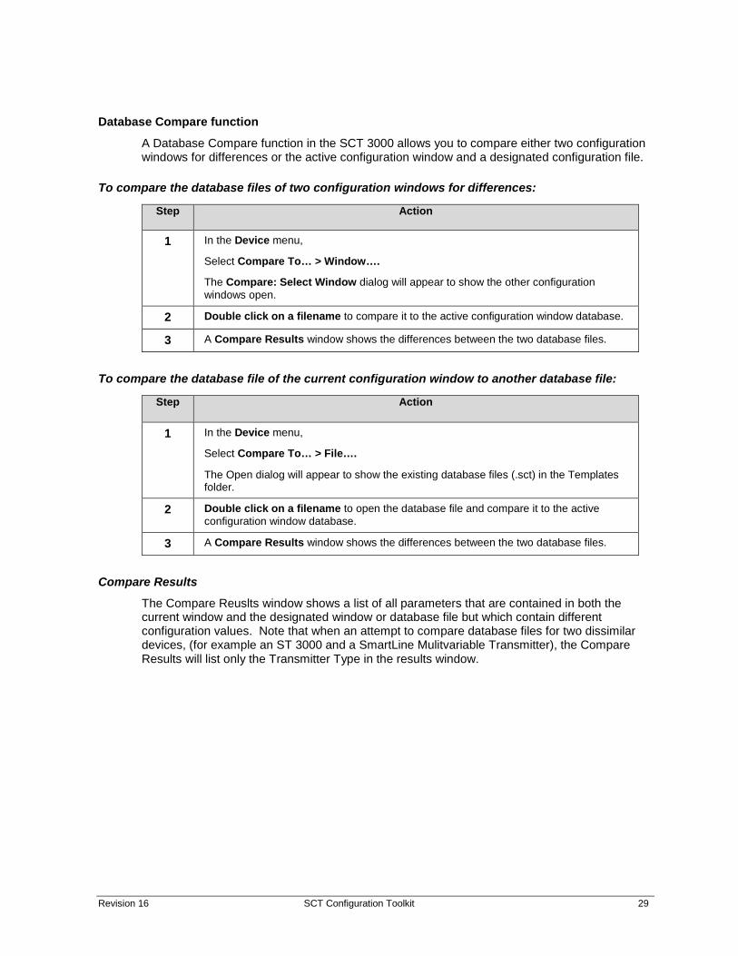
Database Compare function A Database Compare function in the SCT 3000 allows you to compare either two configuration windows for differences or the active configuration window and a designated configuration file.
To compare the database files of two configuration windows for differences:
Step Action
1 In the Device menu,
Select Compare To… > Window….
The Compare: Select Window dialog will appear to show the other configuration windows open.
2 Double click on a filename to compare it to the active configuration window database.
3 A Compare Results window shows the differences between the two database files.
To compare the database file of the current configuration window to another database file:
Step Action
1 In the Device menu,
Select Compare To… > File….
The Open dialog will appear to show the existing database files (.sct) in the Templates folder.
2 Double click on a filename to open the database file and compare it to the active configuration window database.
3 A Compare Results window shows the differences between the two database files.
Compare Results
The Compare Reuslts window shows a list of all parameters that are contained in both the current window and the designated window or database file but which contain different configuration values. Note that when an attempt to compare database files for two dissimilar devices, (for example an ST 3000 and a SmartLine Mulitvariable Transmitter), the Compare Results will list only the Transmitter Type in the results window.

30 SCT Configuration Toolkit Revision 16
This page has been intentionally left blank
Revision 16 SCT Configuration Toolkit 31
7—Using the SCT3000 Tool to Configure Local Display Screens on SMV800
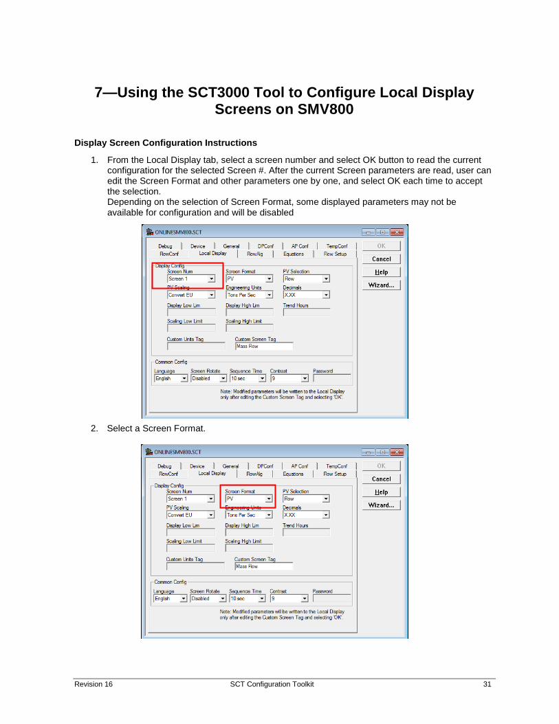
Display Screen Configuration Instructions
1. From the Local Display tab, select a screen number and select OK button to read the current configuration for the selected Screen #. After the current Screen parameters are read, user can edit the Screen Format and other parameters one by one, and select OK each time to accept the selection. Depending on the selection of Screen Format, some displayed parameters may not be available for configuration and will be disabled
2. Select a Screen Format.

32 SCT Configuration Toolkit Revision 16
3. Press ‘Enter’, or click the OK button. If the Screen Format was chosen as ‘PV & Bar’ or ‘PV & Trend’, the Display Low Lim and Display High Lim textboxes should become accessible. If ‘PV & Trend’ was selected, the ‘Trend Hours’ textbox will become accessible.
This screen shows PV and Bar selected as the screen format which activates Display High and Low Limits
When set to PV & Trend, the Display High and Low limits are enabled, as well as the Trend Hours parameter.

Revision 16 SCT Configuration Toolkit 33
4. Select an option in the PV Selection dropdown.
5. Press ‘Enter’, or click the OK button. This selection will affect the options available in the PV Scaling and Engineering Units dropdown lists. The available options directly reflect the available options on the Advanced Display using DE.
6. Select an option from PV Scaling, press enter or click the OK button.
7. Repeat step 7 for Engineering Units and Decimals.
8. If the Screen Format was selected as ‘PV & Bar’ or ‘PV & Trend’, enter a value in Display Low Lim and the press enter or click ‘OK’. Repeat for Display High Lim.
9. If PV Scaling is selected as Linear, or if the PV Scaling is selected as Square Root with Units set to Custom, the Scaling Low and Scaling High Limit boxes will be enabled. Enter a value for each, one at a time, pressing enter or ‘OK’ in between.
10. Enter a value in Trend Hours if available, click ‘OK’ or press enter.

34 SCT Configuration Toolkit Revision 16
11. If the PV Scaling is selected as Linear or Square Root (DP only), and if Custom is selected for Engineering Units, enter a Custom Unit Tag. Click ‘OK’ or press Enter. The box will be disabled if the prerequisites aren’t met.
12. If desired, change the Custom Screen Tag. If the user wants the default screen tag, clear anything that appears in the Custom Screen Tag textbox. Even if no change is needed on the Custom Screen Tag, just hit backspace and reenter the last character. NOTE: When you press Enter or click ‘OK’ after editing the Custom Screen Tag, the write to the Comm/Display will begin. The last item that should be changed is Custom Screen Tag. If you want to change anything before sending the write request, click Cancel and start over.
Common Parameter Configuration There are four common parameters that are currently configurable: Language, Screen Rotate, Sequence Time, and Contrast. Password will be configurable at a yet to be determined time.
1. The common parameters can be configured in any order. After making a change to any of the accessible parameters, confirm that change by clicking ‘OK’. This will write that parameter down to the device. A screenshot of what the SCT Tool will look like is shown below. (Note: As of right now, when writing common parameters, they successfully write to the display, but the comm is returning with error 107, illegal operation).
Items in red box are common parameters.

Revision 16 SCT Configuration Toolkit 35
Display Screen Configuration Parameters:
Table 9 – Display Screen Configuration Parameters
Screen Number
Screen 1 to 8
Screen Format (see below Table 11)
PV selection (see below Table 11)
Screen Units (see below Table 11)
Decimal (see below Table 11)
PV Scaling (see below Table 11)
Display High Limit (Honeywell Float Format)
Display Low Limit (Honeywell Float Format)
Scaling Low Limit (Honeywell Float Format)
Scaling High Limit (Honeywell Float Format)
Trend Hours (see below Table 11)
Custom Tag
30 bytes Character string to identify the displayed value (14 characters + null) Screen Format (see below Table 11)
18 bytes Character string to identify the displayed value (18 characters) (see below Table 11)
Language
English-0, French-1, German-2, Spanish-3, Russian-4, Chinese-5, Japanese-6, Turkish-7, Itaian-8
Sequence Time (3 to 30 Seconds.)
Screen Rotation (1=Enable, 0=Disable)
Password (Read only) (ASCII – 4 Byte data)
Contrast (1-9)

36 SCT Configuration Toolkit Revision 16
Display Screen configuration parameters in detail:
Table 10 - Display Screen configuration parameters details
Name Size Description
Screen Format 1 View display format:
0 – None
1 – Large PV
2 – Bar Graph (Applicable for only Advance Display)
3 – Horizontal Trend (Applicable for only Advance Display)
PV Selection 1
1 – Differential Pressure (InH2O@68F, InHg@0C, InHg@0C, MMH2O@68F, MMHg@0C, PSI, Bar, Millibar, Gram-force/cm^2, Kilogram-force/cm^2, Pascals, Kilopascals, Torr, Atm, InH2O@60F, Megapascals, InH2O@39F, MMH2O@4C, Default InH2O@60F)
2 – Gauge/Absolute Pressure (InH2O@68F, InHg@0C, InHg@0C, MMH2O@68F, MMHg@0C, PSI, Bar, Millibar, Gram-force/cm^2, Kilogram-force/cm^2, Pascals, Kilopascals, Torr, Atm, InH2O@60F, Megapascals, InH2O@39F, MMH2O@4C, Default InH2O@60F)
3 – Temperature (C,F,R,K)
4 – Mass Flow/Volume Flow/No Flow
Mass Flow:
(LbsM per min, LbsM per hour, LbsM per sec, Tons per sec, Tons per min, Tons per hour, Kg per min, Kg per sec, Kg per hour, T per min, T per hour, T per sec ,Grams per sec, Grams per min, Grams per hour)
Volume Flow:
(Gallons per min, Gallons per hour, Gallons per day, Liters per min, Liters per hour, Barrels per day, M^3 per day, M^3 per hour, M^3 per min, M^3 per sec, Ft^3 per sec, Ft^3 per min, Ft^3 per hour)
5 – MB Temperature (C,F,R,K)
6 – Sensor 1 (C,F,R,K) (Temperature sensor measurement)
9 – Sensor 1 Resis (Ohm) (Temperature Sensor Measured Resistance)
10 – Loop Output (milliamp)
12 – Percent Output (Percent)
Screen Units 2 Engineering Units.
Decimals 1 Number of digits to display after the decimal point. Range: 0 – 3
(0 - x, 1 - x.x, 2 - x.xx, 3 - x.xxx)
Name Size Description

Revision 16 SCT Configuration Toolkit 37
PV Scaling 1 0 - None
1 - Convert Units
2 - Linear
3 – Square Root
None, Convert Units, Linear Not Applicable to
Sensor 1 Resis
Loop Output
None, Linear applicable to
% Output
None, Linear, Convert Units applicable to
Diff press,Guage Press, Temp, MB Temp, mass/volume Flow, Sensor1
When Convert Units is selected, the selected PV Selection parameter will show the values in converted Engineering Unit.
Else the values will be shown in default Engineering Unit
Scaling High Limit 4 Display Scaling High Limit ()
Applicable when PV Scaling is Linear
Scaling Low Limit 4 Display Scaling Low Limit ()
Applicable when PV Scaling is Linear
Custom Tag 30 Character string to identify the displayed value (14 characters + null) - sized to support Unicode characters
Custom Unit 18 Character string to identify the displayed unit value (18)
Display Low Limit 4 Display Low Limit (Trend, Bar Graph - usually equal to LRV)
Display High Limit 4 Display High Limit (Trend, Bar Graph - usually equal to URV)
Trend Hours 2 Duration of the trend screen in hours. Valid range 1 – 999
Language 1 Western languages : (English-0, French-1, German-2, Spanish-3, Russian-4, Chinese-5, Japanese-6, Turkish-7, Itaian-8)
Eastern languages : (English-0, Chinese-5, Japanese-6)
Sequence Time 1 Screen Rotation Time (3 to 30 Seconds.)
Screen Rotation 1 Screen Rotation Enable/ Disable option (1=Enable, 0=Disable)
Password 4 Password (Read only) (ASCII – 4 Byte data)
Contrast (1-9) 1 Display Contrast level (1-9)

38 SCT Configuration Toolkit Revision 16
8— Online Help
Online Help Features Online help features allow easy access to information for using the SCT 3000 application. Three types of help are built-in to the SCT.
1. Online Help Topics –SCT 3000 Help topics can be accessed through a Table of Contents or by using the Index and Find function. These functions enable you to locate information about specific topics while in any SCT window.
2. Context-sensitive Help – A help topic can be displayed on a item you select simply by requesting help and selecting the item.
3. Online User Manual – An online document that provides extensive information on how to configure, calibrate, diagnose and monitor the field devices supported by the SCT 3000.
Accessing help Help topics can be accessed several ways.
1. From the Help pull down menu, which is accessible from the SCT 3000 menu bar, choose a help category (see Table 12).
2. Press F1 while focused on a particular window, entry or selection field, menu item or dialog box option.
3. Choose the Help command button that is available in many dialog boxes and configuration forms.
4. Click on the context-sensitive help button on the toolbar and then click on any item.
TIP The Help topics and online user manual provide extensive information about SCT application features and all available online and offline tasks for field device operation.
Table 12 lists the Help menu selections available to you along with a description of the help feature.
Table 11 Help Menu Selections Help Menu Selection
Help Feature
Tip of the Day ... Displays help tips about using the SCT 3000 SmartLine Configuration Toolkit.
Help Topics Opens a window so you can access the SCT 3000 Help topics by using Help’s Table of Contents or by selecting an Index or Find search function.
STT150 Operator Manual
Opens a copy of the STT150 Temperature transmitter operator manual. This selection is available only if you are connected to a STT150 transmitter.
User Manual Opens the SCT 3000 online user manual, which lists the various sections of information available within the manual.

Revision 16 SCT Configuration Toolkit 39
9—Some Vista, Windows 7 and Windows 10 Tips and Notes:
TIP 1: Standard Users can open the files in Root drives (C:\, D:\ etc) or Program Files and its subfolders or Windows folders and its subfolders with Read Only access. They do not have Write permissions on these locations. Administrators have both Read / Write Access to these locations.
Some Popup dialogs and explanation:
Dialog 1:
This dialog will be displayed in two situations;
1. when the user selects File\Save (or selects File Save icon on the Toolbar) to save the file from within the SCT 3000 application to any of the folders below:
o Root Drive (C:\, D:\ etc)
o <Drive>:\ Program Files\ or <Drive>:\Program Files\Some Folder\...
o <Drive>:\Windows\ or <Drive>:\Windows\Some Folder\...
OR
2. when the user selects File\Export command to export the current configuration to a file from within the SCT 3000 application to any of the folders below:
o Root Drive (C:\, D:\ etc)
o <Drive>:\ Program Files\ or <Drive>:\Program Files\Some Folder\...
o <Drive>:\Windows\ or <Drive>:\Windows\Some Folder\...
This simply means that the Standard Users have limited access to these location and the user should save the file to a different location. Preferred location is the Users Public Folder which is located at <Drive>:\Users\Public\Public Documents\...

40 SCT Configuration Toolkit Revision 16
Dialog 2:
1. This dialog will be displayed when the user selects File\Save As to save the file with a new name, from within the SCT 3000 application to any of the folders below:
o Root Drive (C:\, D:\ etc)
o <Drive>:\ Program Files\ or <Drive>:\Program Files\Some Folder\...
o <Drive>:\Windows\ or <Drive>:\Windows\Some Folder\...
This automatically redirects File Save to <Drive>Users\StandardUser folder and you can save to this location. OR you can save to any folder other than the restricted locations listed above.
TIP 2: When switching between Admin and Standard User, always, always Exit the SCT 3000 application to release all the resources (COM port, process HANDLEs etc). If not, the COM port will not be available to the second user and vice versa.
TIP 3: On Installation, the following message indicates you are not an Admin. Only Administrators can install the SCT 3000 Installation setup.
TIP 4: On launching the SCT3000 application (by selecting Start\All Programs\SmartLine Configuration Toolkit\SCT3000), you get the “User Account Control” dialog, similar to the dialog in Figure 6 or Figure 7. In case of Figure 6 type dialog, select “Allow” to proceed, “Cancel” to Cancel. In case of Figure 7 type dialog, select “Continue” to proceed and “Cancel” to Cancel. This is a Vista feature that helps stop unauthorized changes to your computer.

Revision 16 SCT Configuration Toolkit 41
Figure 6: User account control
Figure 7: User account control permission

42 SCT Configuration Toolkit Revision 16
10— Troubleshooting
Overview If trouble arises, it may happen during installation of the SCT 3000 application or during normal operation. Due to differences in computer systems, problems are not always predictable. However this section seeks to provide some suggestions on possible remedies to problems that may occur during installation or operation of the SCT 3000 application.
First this section provides troubleshooting suggestions to help clear up problems. Next, is a listing of all the error codes and communication status messages that are generated by the SCT 3000 application. Last, information and phone contacts to reach Honeywell Technical Assistance are provided if the information in this manual or in the SCT application does not address or remedy a problem.
Troubleshooting SCT Application and the hardware Please note the following consideration when encountering problems with the SCT 3000 application installaton:
1. You can install the SCT 3000 application software on a computer that does not have serial ports. The SCT 3000 will run correctly on these computers but you may only be able to operate in the offline mode.
If you are encountering problems while running the SCT 3000 Software, use the troubleshooting Table 13 to find the symptom and refer to the action to correct the trouble.
Note: For troubleshooting connection issues with HART/DE Bluetooth modem. See References (SCT3000 Configuration Tool Blutooth manual, 34-CT-25-02)
Table 12: SCT 3000 Installation Troubleshooting Symptom Probable Cause Corrective Action
Unable to complete setup procedure for SCT 3000 application installation.
Insufficient disk free space on computer.
Check to make sure that there is enough free disk space on the computer’s fixed disk to allow installation of the SCT 3000 application and its associated files.
The system requirements for application size are listed in Table 1.
Unable to run setup and installation utility for SCT 3000 application.
You do not have write (Admin) privileges in the directories specified for the installation.
See your system administrator.

Revision 16 SCT Configuration Toolkit 43
Troubleshooting SCT 3000 Operation To avoid problems that may occur during initial start-up of the SCT 3000 application, note the following consideration:
Install the SCT 3000 SmartLine Configuration Toolkit application software on the computer before making modem connections.
The troubleshooting table below describes conditions that may occur when running the SCT 3000 application. Please note the probable causes and things to do in order to correct the condition.
Table 13: Troubleshooting SCT operation Symptom Probable Cause Corrective Action
Unable to establish online connection with field device.
Status bar message: NO SERIAL or COM UNKNOWN
Loose hardware connection between computer and field device.
Check all hardware connections.
If you are using the DE modem Option:
a) Hardware components are not properly assembled.
a) See DE Modem hardware assembly and installation on page 14 for procedure.
b) DE modem is not the current version.
b) Check Modem firmware version. In the Help menu, select About Modem. Obtain Modem version 1.0 or greater.
c) The DE modem is not properly installed.
c) See DE Modem hardware assembly and installation on page 14.
d) Hardware is not properly connected between the computer and the Smart field device.
d) See DE Modem connections to a field device (p. 20) for procedure.
e) Serial port not selected. e) Make sure that the serial port on the computer is available for use with the serial hardware interface.
In the View menu, select Options…
Click the General tab. Select a Serial port name that corresponds to the serial port on the computer. (If the computer port names are different, then type the computer’s Serial port name into the edit box on the General tab.)
f) Serial port being used by another application or device. (Other software applications running on the computer may use the serial port, thus making it “unavailable” for SCT 3000 communications.)
f) same as e)
g) Serial port settings are incorrect g) Make sure the port settings are set. See Communication Port and Advanced Settings on page 15.
h) Modem Battery is Low h) Replace the Modem Battery. See Modem Maintenance on page 48.

44 SCT Configuration Toolkit Revision 16
Symptom Probable Cause Corrective Action
Unable to establish online connection with field device.
Status bar message: NO SERIAL or COM UNKNOWN
If you are using the serial hardware interface:
a) Hardware components are not properly connected.
a) See Serial Hardware Interface connections to the STT150 on page 21.
b) Serial port not selected.
OR -
c) Serial port being used by another application or device. (Other software applications running on the computer may use the serial port, thus making it “unavailable” for SCT 3000 communications.)
b) and c) Make sure that the serial port on the computer is available for use with the serial hardware interface.
In the View menu, select Options…
Click the General tab. Select a Serial port name that corresponds to the serial port on the computer. (If the computer port names are different, then type the computer’s Serial port name into the edit box on the General tab.)
Communication errors when trying to connect online to a field device.
a) Loose hardware connection between computer and field device.
a) Check all hardware connections.
b) You are trying to communicate with a field device that is not supported by the current version of the SCT 3000.
b) None.
Refer to the Readme.txt file supplied with the SCT 3000 application for the latest list of Honeywell-supported Smart field devices.
Unable to see Input or Output Calibration tabs when in online mode.
Calibration not enabled in Options… dialog box.
In the View menu, Select Options…
Note: Calibraton tabs are not visible when operating in the offline mode. The computer that is running the SCT 3000 application must be connected to a field device to perform calibration. SCT 3000 software is designed to detect an online connection before it displays the Input Calibration and Output Calibration tabs.
Click the General tab. Check the Enable Calibration in the Customize Options box.
FlowAlg, Flow Setup, and Equation tabs are not visible in the SmartLine Multivariable Transmitter configuration window.
Expert Configuration not enabled in Options… dialog box
In the View menu, Select Options… Click the General tab. Check the Enable Expert Configuration in the Customize Options box.
PV Monitor window values not being updated.
Status Scan not enabled in Options… dialog box
In the View menu, Select Options…
Click the General tab. Check the Enable Status Scan in the Status Scan box.
Unable to display PV Monitor window or use Flow Compensation Wizard.
An application extension file (*.DLL file) is missing or needs to be updated.
The DLL file is available only with Microsoft Internet Explorer 4.01 SP1

Revision 16 SCT Configuration Toolkit 45
SCT Error Codes Error code numbers identify an error that is displayed in an SCT dialog box, in reference to an invalid action. A text message describes the error or invalid action along with the error code for that error type. For example, entering a value in a box that is not within the range of acceptable values will display the dialog box:
Table 11 lists the possible error codes that may appear with a message displayed in an SCT dialog box. The error code is used as a key to the table listing that may further define error and suggest a possible action to correct the problem.
Table 14 SCT Error Codes and Descriptions
Error Number
Error Description
100 General The transaction failed due to a request that was not valid for the current device configuration.
101 Invalid Parameter The selected database item (parameter) could not be accessed because it is not valid for the current configuration.
102 Operation Pending
The transaction failed because another transaction is currently pending.
103 Out of Range The entered value is not within the valid range.
104 Invalid Value The entered value is not a valid floating point number. The acceptable floating point format is +MANTISSAe+EXPONENT.· For example> 6, -1.2, 34.5e-4, 6e8.
105 No Response The attached Smart device did not respond. Make sure that the physical connection is secure.
106 Invalid Response The attached Smart device did not respond properly since the response was not recognizable. The message was probably corrupted by external influences.
107 Illegal operation The requested transaction is not supported by the attached Smart device. Make sure that the device version is compatible with the current release of the SCT 3000. See the ReadMe.txt file supplied with the SCT 3000.
108 Local Mode The attached Smart device could not process the request because it has been placed in local mode. No more transactions can be processed until local mode is disabled.
109 Transmitter Busy The transaction failed because the attached Smart device is too heavily loaded and is unable to process communication requests.

46 SCT Configuration Toolkit Revision 16
Error Number
Error Description
110 Write Protected The value could not be written because the attached Smart device is write protected. The hardware jumper within the device must be repositioned in order to permit write operations.
The STT250 contains a write protection feature that uses a password key in the transmitter configuration.
111 Unable to Format Message
Some or all of the information required to format the desired communications message is not available. Make sure that all database items on the configuration tab cards have valid values.
112 Data Inaccessible
The requested data is inaccessible or not available.
113 Card Not Available
The DE PC card is not present or not functional Make sure that the card is completely inserted in the PCMCIA slot and that the appropriate drivers have been installed.
114 Communications Channel Not Available
The communications channel is temporarily unavailable.
115 No Message Pending
A message response is expected but none is available.
116 Communications Type Unknown
The transaction failed because the type of communications (analog or DE) could not be determined
117 Communications Timeout
The transaction failed due to an internal timeout. The error is usually indicative of a condition that will require restarting the host computer.
118 Parameter Not Ready
Data from the requested database item has not yet been uploaded from the attached Smart device.
119 Parameter Unknown
The database item is valid based upon the current configuration, but its value is unknown (as indicated by a series of question marks -- ?????).
120 Download Failed The download operation failed due to a problem with the current configuration or a communications error.
121 Serial Port is not available
The serial port is not available or is not functional. Loose hardware connection. Make sure that the physical connection is secure.

Revision 16 SCT Configuration Toolkit 47
Status Bar The status bar appears at the bottom of the SCT 3000 application window. To display (or hide) the status bar, use the Status Bar command in the View menu.
The left area of the status bar describes actions of menu items as you use the arrow keys to navigate through menus. This area similarly shows messages that describe the actions of the toolbar buttons as you depress them, before releasing them. If after viewing the description of the menu item or toolbar button command you wish not to execute the command, then release the mouse button while the pointer is off the menu item or toolbar button.
The status bar also displays additional information in two of the four boxes on the right side of the bar. The last two boxes contain status of the communications link between the computer and the field device. See the following figure and table.
The table below describes the messages that are displayed in boxes A, B and C.
Status Description Box A – Indicates the status of hardware interface. SERIALOK NO SERIAL SERIAL BAD
Serial interface hardware detected and is communicating No serial interface detected Serial interface fault
Box B – Indicates the selected communications mode. ANALOG DE4BYTE DE6BYTE COM UNKNOWN
Device is communicating in the analog mode. Device is communicating digitally (DE mode) in either a 4 byte or 6 byte format. Indicates that the current view is not online.
Box C* – Indicates DE modem status. Modem :OK
DE modem is functioning normally
Modem :Unknown
Modem Status is Unknown. Possible reasons: No Serial Communication Modem is Bad Modem Battery is bad
Modem : Bad Modem is Bad. Possible reasons: Low battery, ROM Failure and ROM Failure Low battery and ROM Failure Low battery and RAM Failure ROM and ROM Failure ROM Failure
Modem : Low Battery Modem Battery is Low
a) *DE Modem only
B
o

48 SCT Configuration Toolkit Revision 16
Modem Maintenance When you are not using the SCT 3000 software, please close the application. As long as the application is running, the modem battery will be used. Modem constantly checks for DE Network state (Analog, DE 4 Byte or 6 Byte), any break in the connections (No Serial, COM UNKNOWN etc. ) and Modem Status (Low Battery, ROM Failure, RAM Failure etc)
When to replace battery The battery should be replaced:
-when one of these messages appears in the Modem Diagnostics display (in the Modem Status box, lower right):
Low Battery
Unknown (after checking wiring connections)
ROM Failure
RAM Failure
-in periodic maintenance, when voltmeter test indicates low voltage.
When to replace battery
• Modem LED does not turn on when power is switched on
• SCT 3000 does not show SERIAL OK status on the status bar even when the LED is ON and correct comm port is selected.
• When the measured battery voltage is < 2.5 volts
• Low Battery status
• Unknown status on SCT status bar (after checking wiring connections)
• ROM Failure
• RAM Failure
• In periodic maintenance, when voltmeter test indicates low voltage.

Revision 16 SCT Configuration Toolkit 49
How to replace battery Before replacing, obtain a new CR-V3p battery. Honeywell recommends Panasonic CR-V3p. Other models may perform adequately but not as well.
WARNING! Never remove the cover of the battery compartment, or attempt battery replacement in areas designated as having a potentially Explosive atmosphere.
Step Action
1 Remove the screw that holds the battery cover in place, and remove the cover from the battery compartment.
2 Press lightly on the bottom of the battery as shown in the picture below, rotating the battery outward at the top. Note the orientation of the battery in the compartment, and then remove it from the case.
3 Noting orientation of the new battery and the terminals, insert the new battery into the case.
4 Replace the cover and the retaining screw.

50 SCT Configuration Toolkit Revision 16
Appendix
ATTENTION Note that the SCT 3000 application is not compatible with Norton File Assist. The SCT 3000 Setup program is coded to detect the presence of Norton File Assist on the computer and, if present, adds a line to the program to ensure that Norton File Assist does not run with the SCT 3000 application.

Revision 16 SCT Configuration Toolkit 51
Glossary
Term
Meaning
Analog (R100/R200) Protocol
The Honeywell-proprietary analog communications protocol for SmartLine field instruments as defined by the Smart Field Network (SFN) Specification.
DE (Digitally Enhanced) Protocol
Honeywell-proprietary digital communications protocol for SmartLine field instruments as defined by the Smart Field Network (SFN) Specification.
Download Refers to the action of transferring an SCT 3000 configuration database file from the host computer to a connected Smart field device.
GUI Graphical User Interface is a term for the graphical images displayed on the computer screens that are generated to simplify the interpretation and selection of data or actions by the computer user.
HART/DE Bluetooth Modem
HART protocol and Honeywell Digitally Enhanced Modem that communicates via Bluetooth
PC Personal Computer
Smart Field Network (SFN)
Refers to the Honeywell Smart Field Network (SFN) protocol that defines communication mechanisms for Honeywell analog and digital field devices.
Tag ID Refers to an ASCII field used to uniquely identify a field device at a specific customer location
Upload Refers to the action of transferring the field device’s data to an SCT 3000 configuration database window.
52 SCT Configuration Toolkit Revision 16
INDEX
A
Appendix ................................................................ 50 Application window ............................................... 25
B
Before You Begin ..................................................... 6
C
CD ROM drive .......................................................... 6 CD ROM Installation .............................................. 10 Common Parameter Configuration ....................... 34 Computer Requirements ......................................... 6 Computer specifications .......................................... 6 Connecting to a field device .................................. 19
D
Database compare function .................................. 29 Database file
Exisitng ............................................................... 28 New .................................................................... 27
Database file management .................................... 27 Display Screen Configuration Instructions ............. 31 Display Screen Configuration Parameters ............ 35 Display specification ................................................ 6
F
Field devices supported ........................................... 3 Flow Wizard ............................................................. 5
G
Glossary ................................................................. 51
H
Hardware installation ............................................ 13 Hardware Installation
HART/DE Bluetooth Modem .............................. 13 HART/DE Modem hardware assembly and
installation ..................................................... 14 SCT Hardware .................................................... 13 Serial Hardware Interface (for use with STT 150
only) ............................................................... 17 Hardware specifications
Serial hardware interface .................................... 8 Smartline Option Module .................................... 8
HART/DE Bluetooth Modem ................................. 13 HART/DE Modem hardware assembly and
installation ......................................................... 14 hazardous locations ........................................... 7, 19 Help
Accessing ........................................................... 38 Help menu ............................................................. 38
I
Installation utility ..................................................... 9 Interface cable .... See also Serial hardware interface
L
Language Support .................................................... 5
M
Maximize and minimize buttons ........................... 25 Menu bar ............................................................... 25 Modem Maintenance ............................................ 48
O
Offline mode ............................................................ 4 Online Help ............................................................ 38 Online help features .............................................. 38 Online mode ............................................................ 4 Operating systems ............................................... 4, 6
P
Parameter checking ............................................... 28 Pointing device ........................................................ 6 Ports (I/O for printer and serial hardware interface)
............................................................................. 6 Power source ........................................................... 6 Printing a database document .............................. 28 PV Monitoring ......................................................... 4
R
RAM requirements .................................................. 6

Revision 16 SCT Configuration Toolkit 53
S
SCT 3000 Compatible computers ....................................... 7 Connections to a field device ............................ 19 Error codes ........................................................ 45 Hardware ............................................................ 7 Installation utility ................................................ 9 PC specifications ................................................. 6 Software compatibility ........................................ 7 Toolkit contents .................................................. 1
SCT 3000 application installation CD ROM ............................................................. 10
SCT 3000 application program .............................. 19 SCT 3000 banner window ..................................... 23 SCT 3000 Installation............................................... 9 SCT 3000 Software Application and Setup .............. 9 SCT 3000 software features ............................... 4, 25 SCT Error Codes ..................................................... 45 SCT Hardware........................................................ 13 Serial hardware interface........................................ 7
Assembly and installation ................................. 17 Description ........................................................ 17
Serial Hardware Interface (for use with STT 150 only) .................................................................. 17
Smartline Configuration Toolkit, SCT 3000 Description .......................................................... 1
SMV800 configuration screens using SCT3000 ..... 31 Software Installation ............................................... 9
CD ROM Installation .......................................... 10 SCT 3000 Installation ........................................... 9 SCT 3000 Software Application and Setup .......... 9
Start up and Working Online ................................ 19 Getting Online Quickly ...................................... 19 SCT 3000 Application ........................................ 19 SCT 3000 Features ............................................. 25
Starting the SCT 3000 application ......................... 22 Status bar .............................................................. 25 Status Bar .............................................................. 47 Status bar messages.............................................. 47 System Requirements ............................................. 6
Before You Begin ................................................. 6 Computer Requirements .................................... 6 SCT Hardware ...................................................... 7 Software Compatibility ....................................... 7
T
Toolbar ............................................................. 25, 26 Troubleshooting ............................................... 39, 42
Error codes ......................................................... 45 Modem Maintenance ........................................ 48 SCT 3000 operation ............................................ 43 SCT Error Codes ................................................. 45 Status Bar ........................................................... 47
Troubleshooting SCT 3000 Operation .................... 43 Troubleshooting SCT Application and the hardware
........................................................................... 42 Troubleshooting tables .......................................... 42
U
Using the SCT 3000 Offline .................................... 27 Using the SCT3000 Tool to Configure Local Display
Screens on SMV800 Common Parameter Configuration ................... 34
Using the SCT3000 Tool to Configure Screens on SMV800 .............................................................. 31
W
Working offline ................................................ 26, 27 Working Offline ...................................................... 27
Using the SCT 3000 Offline ................................ 27 Working online ................................................ 19, 26

For more information To learn more about Configuration tools, visit www.honeywellprocess.com Or contact your Honeywell Account Manager
Process Solutions Honeywell
1250 W Sam Houston Pkwy S Houston, TX 77042
Honeywell Control Systems Ltd Honeywell House, Skimped Hill Lane Bracknell, England, RG12 1EB
34-ST-10-08, Rev.16 August 2020 2020 Honeywell International Inc.
Shanghai City Centre, 100 Jungi Road Shanghai, China 20061 www.honeywellprocess.com
Sales and Service For application assistance, current specifications, ordering, pricing, and name of the nearest Authorized Distributor, contact one of the offices below.
ASIA PACIFIC Honeywell Process Solutions, Phone: + 800 12026455 or +44 (0) 1202645583 (TAC) [email protected] Australia Honeywell Limited Phone: +(61) 7-3846 1255 FAX: +(61) 7-3840 6481 Toll Free 1300-36-39-36 Toll Free Fax: 1300-36-04-70 China – PRC - Shanghai Honeywell China Inc. Phone: (86-21) 5257-4568 Fax: (86-21) 6237-2826 Singapore Honeywell Pte Ltd. Phone: +(65) 6580 3278 Fax: +(65) 6445-3033 South Korea Honeywell Korea Co Ltd Phone: +(822) 799 6114 Fax: +(822) 792 9015
EMEA Honeywell Process Solutions, Phone: + 800 12026455 or +44 (0) 1202645583
Email: (Sales) [email protected] or (TAC) [email protected]
Web
Knowledge Base search engine http://bit.ly/2N5Vldi
AMERICAS Honeywell Process Solutions, Phone: (TAC) (800) 423-9883 or (215) 641-3610 (Sales) 1-800-343-0228
Email: (Sales) [email protected] or (TAC) [email protected]
Web
Knowledge Base search engine http://bit.ly/2N5Vldi