Embed Size (px)
Citation preview

SmartLam GL13S Design Guide 1 Aug 2018
SmartLam GL13S (NON pre-cambered)
Design Guide
Edition 1 2018


Scope of this publication This Design Guide and Load Tables assist in the selection of SmartLam GL13S for some of the common structural elements in domestic construction. Methods of developing lateral restraint and providing adequate support, adequate anchorage against wind uplift, and overall structural stability are outside the scope of this publication. Information on the above matters can be obtained from AS 1684 Residential timber-framed construction or from a structural engineer experienced in timber construction. Tilling Timber have structural engineers within the SmartFrame Design Centre who can be contacted for advice on matters concern-ing the use of its SmartFrame engineered timber products in timber construction via the technical support Helpline on 1300 668 690 or e-mail at [email protected]. Substitution of other products All load tables in this document are designed using the characteristic properties of GL13S defined in table 7.1 of AS 1720.1, manufactured to AS/NZS 1328 by quality producers and distributed by Tilling Timber Pty Ltd. Copyright Copyright of this publication remains the property of Tilling Timber Pty Ltd, and reproduction of the whole or part of this publication without written permission from Tilling Timber Pty Ltd is prohibited. Certification As a professional engineer, qualified and experienced in timber engineering, I certify that the use of the SmartLam GL13S members as shown in these tables, and installed in accordance with the provisions of this Design Guide, complies to the Building Code of Australia. These Span Tables have been prepared in accordance with standard engineering principles, the relevant test reports and Australian standards, ie:
AS 1720.3 Residential timber-framed construction
AS 1720.1 Timber structures - design methods
AS 4055 wind loads for houses
AS/NZS 4063 Characterisation of structural timber
AS/NZS 1328 Glue laminated structural tmber - performance requirements and minimum production requirements.
GLTAA Unified design criteria
CRAIG KAY RPEng, RPEQ-5100, EC-1961, PB0730, CC56335 C NER
National Product Engineer
SmartFrame Product Warranty
Tilling Timber warrants that its SmartFrame Engineered Wood products will be free from manufacturing defects in workmanship and material.
In addition, provided the product is correctly installed and used, Tilling Timber warrants the adequacy of its design for the normal and expected life of the structure.
This warranty is backed by the full resources of Tilling Timber and by underwritten product liability insurance.
Tilling Timber Pty Ltd
31-45 Orchard Street
Kilsyth Vic 3137
Ph: +61 (0)3 9725 0222 Fax: +61 (0)3 9725 6569
Email: [email protected]
Table of Contents
Introduction 1 GLTAA deflection limits 1
Ordering SmartLam GL13S 2
Installation - Preparatory work 2 - Deflection 2 - Verticality 2 - Notches 2 - Holes for services 2 - Birdsmouthing 3 - Eaves overhang 3 - Multiple SmartLam GL13S section beams - Top loaded beams 3 - Side loaded beams 3 - Steel and timber post fixing 4 Storage and handling 4
SmartLam GL13S design/effective span 5
Durability and weather exposed application 5
Protection systems - During construction 6 - Exterior applications 6 - Painted SmartLam GL13S 6 - Design and construction detailing tips 7
Fire rating (resistance) 7
Checking of SmartLam GL13S 8
Designing with SmartLam GL13S - Product specification 9 - Limit state design characteristic 9 - Strength reduction factors 9 - Duration of load 9 - Partial seasoning factor 9 - Length and position of bearing 9 - Load sharing 9 - Stability 9 - Temperature 9 - Beam section properties 10 Span tables 12-44
The information contained in this product brochure is current as at August 2018 and is based on data available to Tilling Timber Pty Ltd at the time of going to print. Tilling Timber Pty Ltd has used its reasonable endeavours to ensure the accuracy and reliability of the information contained in this document and, to the extent permitted by law, will not be liable for any inaccuracies, omissions or errors in this information nor for any actions taken in reliance on this information. Tilling Timber Pty Ltd reserves the right to change the information contained in this document without prior notice. It is important that you call the technical support customer Helpline on 1300 668 690 to confirm that you have the most up to date information available.

SmartLam GL13S Design Guide 1 Aug 2018
Introduction
Tilling Timber offer multiple GL13S options, with both a softwood and hardwood glulam beams available. SmartLam GL13S beams are manufactured for Tilling Timber by 3rd party audited quality glulam manufacturers to AS/NZS 1328. SmartLam GL13S Glulam beams are engineered timber products with high strength, dimensional stability, great load carrying capaci-ty and superior fire resistance. All timber used for laminating is carefully selected from production and graded according to specification. After trimming to the de-sired size, all stock is kiln dried to 12% average moisture content, to ensure efficient bonding in the gluing operations. The lamina-tions are finger jointed by machine, with glue being cured by cold press system and controlled temperature. Benefits of SmartLam GL13S
Cost Effectiveness - SmartLam GL13S beams high strength to weight ratio allows you to design for maximum loads over large spans with the smallest possible end sections. Product Quality - All SmartLam GL13S beams are manufactures in accordance with AS 1328 Glue Laminated Structural Timber and the Glued Laminated Timber Association (GLTAA) Industry standard GLTAA-4-91. Fire safety - Extensive fire test data shows that large end section timber performs well in fire situations due to the formation of a protective layer of char which usually occurs at a temperature
around 250o C. This charred area inhibits the effects of the fire on the inner portion of the timber component, hence it maintains structural load support for measurable periods of time as the fire progresses. Conversely, steel loses its strength rapidly as the temperature is raised. At about 550oC, it has lost about 50% of its original bending strength, and by 750oC it has lost 90%. Timber does not loose strength in the same way, with the loss of section size through charring the major reason for any strength reduction. Fast easy erection - Timber is a user friendly building material, requiring no special tools other than those a normal builder would use, and with SmartLam GL13S beams, installation is fast, easy and efficient. Environmental responsibility - SmartLam GL13S beams are made from timber from sustainable managed forests, a natural resource that is friendly to the environment. Low maintenance - In most applications, SmartLam GL13S beams will require little or no maintenance other than that which you would ordinarily carry out to any structural material. Natural beauty - The natural beauty of timber is desired and highly appropriate in many architectural applications. Appearance Grade B SmartLam GL13S beams allow you to build timber's natural warmth and beauty into your designs.
Serviceability Criteria The deflection limits (serviceability ) applied in these tables and reproduced in Table 1 below, are in accordance the Glued
Laminated Timber Association of Australia (GLTAA) Unified Design Criteria and in some circumstances, differ for those listed in AS 1720.3 -2016.
Long term Short term Member type
j2 x DL j2 x (DL+0.5 kPa) LL Serviceability WL
Bearers (floor loads only) L/300 or 12 mm L/360 or 18 mm
Bearers (with roof loads) L/300 or 12 mm L/360 or 18 mm L/150
Joists L/300 or 15 mm L/360 or 9 mm
Lintels (with roof loads only) L/300 or 9 mm L/250 or 9 mm L/150
Lintels (with roof and floor) L/300 or 9 mm L/360 or 9 mm L/200
Strutting, hanging, and counter beams L/300 or 15 mm L/270 or 15 mm L/150
Hanging/Strutting, Counter/Strutting beams L/300 or 12 mm L/300 or 12 mm L/150
Roof beams, rafters, hips L/300 or 20 mm L/250 L/150
Patio or verandah beams L/400 or 10 mm L/250 or 12 mm L/200
Where: 1. DL = Dead load, LL = Live load, WL = Wind load, 2. j2 = Creep modification factor Clause 2.4.1.2 AS 1720.1
Table 1: GLTAA Serviceability Criteria
SmartLam® GL13S

SmartLam GL13S Design Guide 2 Aug 2018
Ordering SmartLam GL13S
SmartLam GL13S glulam can be purchased with different appearance grades. AS/NZS 1328.2 defines 3 appearance grades:
Appearance Grade A - Sanded with any voids filled - intended for applications where appearance is important and clear or painted finishes are used
Appearance Grade B - intended for applications where appear-ance is important but where a planed finish is acceptable
Appearance Grade C - intended for applications where appear-ance is unimportant
SmartLam GL13S B grade
Stock SmartLam GL13S will be supplied without pre-
camber (straight) in B grade finish unless otherwise spe-
cifically requested.
Protection and handling
Care should be taken during delivery to avoid marking and to avoid damage. Unloading of trucks should be done by hand or with a crane, do not drop or dump members. During unloading with lifting equipment, use fabric or plastic belts or other slings which will not mark the wood. If chains or cables are used, provide protective blocking or padding. Guard against soiling, dirt, footprints, abra-sions, or injury to sharp edges or corners.
Installation
Preparatory work
Carefully unload and handle the laminated members at job site to prevent surface marking and damage. If laminated timber is to be stored before erection, place it on blocks well off the ground with individual members separated by strips so that air may circulate around all four sides. The top and the sides of storage pile shall be covered with moisture resistant covering. Wrapping shall be left intact, but individual wrappings shall be slit or punctured on the lower side to permit the drainage of water that may have accumu-lated. Before erection, the assembly should be checked for any damage from water or handling, prescribed camber, and accuracy of anchorage connections.
Laminated beams can be nailed into place in the same way as solid timber beams. Alternatively, a range of plates are available for end fixing. For larger beams, special purpose, engineer designed end fixing should be used.
Deflection
All structural members deflect downwards when dead loads are applied, and therefore it is important to allow for this deflection structurally and/or aesthetically in the selection of the beam sizes. The "Deflection Limits" table on page 1 details deflection limits for various applications
Verticality
SmartLam GL13S members must not be installed out of plumb more than height/500. Notches
Large notches and holes in Glulam beams should normally be avoided as they cause abrupt changes in cross section and disrupt the stress flow in the structure. This gives rise to tension perpen-dicular to the grain and shear stresses around the holes and notch-es. For this reason, notches seriously reduce the strength of a beam, particularly if located in the tension zone of a beam. Unless specific allowance has been made in the design, no notches shall be made without first obtaining the advice of an engineer. Design rules are set out in AS 1720.1 Timber Engineering Code and should be followed closely when considering notching anywhere in a Glu-lam beam.
Holes for services
Horizontal Holes - Like notches, holes in a Glulam beam remove wood fibre, reduce the net area of the beam at the hole location, and introduce stress concentrations. For this reason, horizontal holes in Glulam beams are limited in size and location to maintain the structural integrity of the beam. Figure 2 below shows the zones of a uniformly loaded, simply supported beam where field drilling of holes may be considered.
Field drilled horizontal holes should be for access only and should not be used as attachment points for brackets or other load bear-ing hardware unless specifically designed as such by the Engineer/Designer.
Regardless of the hole location, the net section of the beam re-maining should be checked for flexure and horizontal shear.
Vertical holes - As a rule of thumb, vertical holes drilled through the depth of a Glulam beam cause a reduction in capacity at that loca-tion directly proportional to the ratio of 1½ times the diameter of the hole. For example, a 25 mm hole drilled in a 150 mm wide beam would reduce the capacity of the beam at that section by ¼. For this reason, where it is necessary to drill vertical holes through a Glulam member, the holes should be positioned in areas of the member that are stressed to less than 50% of the design in bend-ing.
Holes for support of heavy equipment - Heavy equipment or piping suspended from Glulam should be attached so that the load is ap-plied to the top of the member to avoid tension perpendicular to the grain stresses. Any horizontal holes required for support of significant weight, such as suspended heating and cooling units or main water lines, must be located above the neutral axis of the member and in a zone stressed to less than 50% of the design flex-ural stresses.
Figure 2 - Zones where horizontal holes are permitted in a uniformly loaded simply supported beam
D/4
D/4
D/2High shear zone
Zon es wh ere h orizon tal ho les fo r load -bearing fas teners are p ermitted
Zone s wher e horiz ontal h oles ar e perm itted
High flexu re zo ne
High flexu re zo ne
High shear zone
L/8 L/8 L./8L/8 L/2
Span = L
“C” indicates pre-camber “S” indicates no-pre-camber (straight)
Appearance grade

SmartLam GL13S Design Guide 3 Aug 2018
Installation
INCORRECT
Can cause sp litting due to i nduc ed tension perpendi cularto the grain stresses,reduces shear strengthand rap id drying due t o exposed end grain
CORRECT
D
Overh ang
40
50
Min imum d epth ofembedme nt = D /2
M10 galvan isedcoac h screw s
Birdsmouthing Figure 3 - Birds mouthing details for SmartLam GL13S Eaves overhang Figure 4 - Eaves over hang details for SmartLam GL13S Note: Refer to AS 1684 Residential timber-framed construction code for overhang member size. Allowable Eaves overhangs 1. Non Cyclonic Areas
a. Beams for flat or similar roofs - Not Birds mouthed: Eaves overhang shall not exceed 40% of the actual beam span.
b. Beams with conventional pitched roofs - Birds mouthed to one third their depth:
i. Sheet roof - 20% of actual beam span
ii. Tiled roof - 30% of actual beam span
2. Cyclonic Areas Recommendations as per above, but reduced as follows:
i. Non Birds mouthed - 25% of actual beam span
ii. Birds mouthed-
iii. Sheet roof - 10% of actual beam span
iv. Tiled roof - 20% of actual beam span
Multiple SmartLam GL13S section beams Vertical laminations may be achieved by adopting the principle described in clause 2.3 of AS 1684, however, due to the thickness of SmartLam GL13S, nails are NOT suitable for combining SmartLam GL13S beams. Experience with Glulam beams indicates that multiple member laminations individual components may cup as a result of the ingress of moisture between laminates during construction. The suggested method of vertical lamination shown below provides a greater level of fixity between individual components, and com-bined with the use of a temporary waterproof membrane and an elastomeric adhesive prevents moisture penetration between the laminates.
Recommended “during construction” protection from weather for multiple SmartLams.
Top loaded beams (Symmetrical loading)
The edges of the individual sections must be carefully aligned to each other so that the composite beam is flat, allowing the ap-plied loads to be equally shared. It is recommended that there be 2 rows of galvanised M12 bolts at 600 mm centres. Side loaded beams (Non – symmetrical loading) When a load is applied to one side of a built-up SmartLam GL13S or an unbalanced load is applied to both sides, the elements of the built up beam shall be attached such that the applied load is distributed equally to all elements. Like the minimum connection
Bead of
Elastomeric
adhesive
Bead of
Elastomeric
adhesive
Temporary
Waterproof
membrane
60 mm Bolt spacing
3 pieces of65 or 85 mm
2 pieces of 65 or 85 mm
Combination 2Combination 1
55 mm diameterwasher as per table4.12 - AS 1720.1
50 mm Min
50 mm MinStagger row of bolts

SmartLam GL13S Design Guide 4 Aug 2018
shown above, the connection is made with bolts, with the allowa-ble floor load width supported by either outside member shown in the table below. Maximum floor load width supported by either out-side member (mm)
Notes:
1. Table values are for 40 kg/m2 floors.
2. Bolts are to be grade 4.6 commercial bolts conforming to AS 1111. Bolt holes are to be a maximum of 13 mm diameter and are to be located NOT less than 50 mm from either edge.
3. All bolts shall be fitted with a washer at each end, of a size NOT less than that given in AS 1720.1 table 4.12.
How to use the maximum uniform side load table
Example: Beam of 2 SmartLam GL13S loaded on both side (Combination 1)
FLW 1 = 4800 mm, FLW 2 = 5300 mm
Total FLW = 4800 + 5300 = 10100 mm.
1. Use SmartFrame software or these SmartLam GL13S safe load tables to size the two member section to support the FLW of 5100 mm.
2. Choose the larger of the side FLW's carried by the beam, in this case 5300 mm.
3. Enter the table at the "Combination 1" row and scan across to a table value greater than 5300 mm. The first value in the row at 10200 mm is greater than the 5300 mm required.
4. Thus adopt 2 rows of 12 mmФ x bolts at 600 mm centres
Steel and Timber fixing to SmartLam GL13S
Storage and handling of SmartLam GL13S
1. Store SmartLam GL13S flat on a hard, dry surface
2. If surface isn't paved, the ground should be covered with a polythene film
3. Keep covered with waterproof material that allows bun-dles to "breathe"
4. Use bearers (bolsters) between the ground and the first bundle (4 metre max spacing)
5. Use 100 x 50 timber flat between bundles at same spacing as bolsters
6. Take great care to rewrap remaining material after open-ing bundles
7. Timber "grows" in thickness and depth when allowed to get wet....KEEP DRY!
8. Timber products with high MC has short term reduction in Characteristic Strengths …. KEEP DRY!
9. Under NO circumstances is stored SmartLam GL13S to be
in contact with the ground.
12 mm Ф bolts Combination (see details below) 2 rows at 600 ctrs 2 rows at 300 ctrs
Combination 1 10100 20200
Combination 2 16150 20200
Installation (cont’d)
= 5300 mm= 4800 mmFloor load width 1 Floor load width 2
Bearing le ngth
Column c ap to provid ereq uired bearin g len gth
and width to fu lly su pportbea m, incl uding m ultiple
bea m asse mblies
Beam to be late rally res tained to pre vent i ttwis ting or rotating at the supp ort
Bea m cap to providereq uired bearin g len gth and width to fu lly su pportbea m, incl uding m ultiplebea m asse mblies
Use bearers to keep stacked material away from damp surfaces. Align bearer vertically
Bearers at a max. of 4.0 m centre

SmartLam GL13S Design Guide 5 Aug 2018
SmartLam GL13S Design /Effective span
span difference effective span resultant span description
10% Max main span continuous
10 – 30% 1.1 x main span continuous
Above 30% difference main span single
span difference = (major span - minor span) x 100 (major span + minor span) The span to use in the case of unequal continuous spans is the "resultant span description " as shown in the table above. (Note: It is recommended for the most accurate designs, that the SmartFrame software be used.)
Normal structural analysis uses the centreline representation of the member. The term “span” can be defined in a number of ways and these are defined as follows: Clear span. This is the distance between the faces of any support. It is generally the one easiest to measure and read from the draw-ings
Nominal span/centre-line span. This is the distance between the centre of the supports. This span is used to determine bending moments and deflections for continuous spaning members
Design span/Effective span. This is the span used for single span members to determine the bending moment, the slenderness of bending members and the deflections. In NZS 3603 this is the dimension referred to as “L”, and is defined below.
Design span/Effective span is the distance between -
The centre of the bearing at each end of a beam where the bearing lengths have NOT been conservatively sized
The centre of notional bearing that have been sized appro-priately, where the size of the bearing IS conservative.
Effective span (design span) L
Area of supportrequired for
bearing
Length of originalbearing (oversized)
.
Length ofeffectivebearing
Centre-line span (distance betweeen centres of supports)
Clear span (Distance between face of supports)
Effective span (design span L)
Clear span (Distance between face of supports)
Diagram (a) shows beam where bearings have been designed appropriately. The effective span is taken as the distance between the centre of each bearing area
Diagram (b) shows beam where bearings at each end have been oversized. (This is frequently the case for beams that bear onto brickwork or concrete walls where the thickness of the wall is in excess of the area required to give the beam bearing capacity). To find the correct effective span: 1. Calculate the minimum
bearing required to carry the loads satisfactorily
2. Add minimum bearing length to “clear span” distance
SmartLam durability and weather exposure
30
External, above ground, exposed
External, above ground, protected. *
Internal, fully protected, ventilated
AS 1684 definitions of exposure zones within a structure
* External timbers are regarded as protected in AS 1684 if they are covered by a roof projection (or similar) at 30° to the vertical and they are well detailed and maintained (painted and kept well ventilated).

SmartLam GL13S Design Guide 6 Aug 2018
SmartLam GL13S are manufactured from kiln dried timber (MC less than 15%), and therefore need to be protected from moisture cycling that can occur from:
Exposure to direct sun and rain (including during construc-tion)
Contact or close exposure with moisture laden porous material (e.g. Concrete blocks)
Exposure to extreme environments such as dry heating systems (e.g. slow combustion wood heaters), air condi-tioning, large north or west facing windows or moisture laden environments such as pool enclosures.
SmartLam GL13S protection methods
1. During Construction (pre-water proof roof) SmartLam GL13S is supplied WITHOUT any short term construction sealer. However if SmartLam GL13S is expected to be exposed for an extended period or become wet, it is recommended that the beam be sealed with a construction sealer that is compatible with the final paint or varnish finish, or wrapped in plastic to provide protection (plastic must allow for drainage and air circulation to breath). Examples: i. If the SmartLam GL13S is installed inside a building without
direct exposure to air-conditioning such as in wall cavity, NO protection to the beam is required.
ii. If the SmartLam GL13S is installed inside a building with direct exposure to air conditioning or dry heat then a sealer is required.
iii. If the SmartLam GL13S is under the eaves and protected from direct rain and sun, it is recommended that the con-struction sealer be lightly sanded and a finish coat of com-patible premium quality paint be applied. (In accordance with paint manufacturer’s specifications).
iv. If the SmartLam GL13S is exposed to the sun or weather refer to “Exterior Applications” below.
Treatment options
SmartLam GL13S may be ordered untreated or with preservative treatment to the H2 and H3 hazard class for protection against insect attack and biological decay respectively. (All Pine based GL13S is preservative treated against the European House borer Beetle)
Treatment for a service at a higher hazard class satisfies all require-ments for service at a lower hazard class. Products treated to H3 therefore meet or exceed the requirements for H1 and H2 applica-tions. Table 1 of Appendix A in AS/NZS 1604.5 is a guide to hazard classi-fications for various end-use applications. This table is for guidance only, and only lists limited application. Example applications 1. Covered alfresco and garage beams Alfresco beams constructed to comply with the diagram adjacent are classified in AS 1684 as External, above-ground, protected and can be an untreated Class 4 durability timber.
SmartLam GL13S beams treated to H2 or above are ideal for alfresco and garage beam applications
A SmartLam GL13S in this application must be correctly painted with a premium quality protective finish See 3. Painting treated SmartLam GL13S below.
2. External, above ground, EXPOSED Untreated SmartLam GL13S beams must NOT be used in external, above ground , EXPOSED applications without the following: i. H3 treated to AS/NZS 1604.5
ii. Correctly detailed (e.g. End caps, good drainage and venti-lation). See “Design & Construction detailing tips” below
iii. Correctly painted as per covered alfresco beam example above
It is important that an inspection and maintenance programme, based on exposure level and the paint manufacturer’s recommen-dations be prepared. 3. Painting treated SmartLam GL13S (a) General To provide the longest service life of the SmartLam GL13S, it is recommended the SmartLam GL13S are painted with an exterior paint with a Light Reflectance Value (LRV) greater than 30%. Heat reduction exterior paints should be used where the desired colour is dark or has a LRV of less than 30% The heat reflective paints colours should be limited to a Total Solar Reflectance (TSR) value greater than 29%. Any paint or stain must be recommended by the manufacturer as being suitable for the proposed application and must be applied in a manner in strict compliance to the manufacturer's recommenda-tions
1. The wood must be dry and clean prior to applying any fin-
SmartLam durability and weather exposure
30
External, above-ground,protect ed*
External, above-ground,exposed
* member must also be well detailed and maint ained (painted or stained and kept well ventilat ed)

SmartLam GL13S Design Guide 7 Aug 2018
ish coating. If initial cleaning of the treated wood is need-ed, it is recommended that the project be cleaned with a deck cleaning product and allow to fully dry
2. At this time, a clear water repellent can be added to the project. If applied, allow 8 weeks prior to the application of a semi-transparent stain or paint
3. If no water repellent is added, an oil based stain can be applied to the clean, dry wood in 30-60 days from treat-ment date.
4. A water based stain can be applied to the clean, dry wood in 45-70 days from treatment date.
5. Depending on the treatment method used, if the wood is left uncoated and without UV protection:
6. i. The typical brown colour of the Copper Quat treat-
ed wood will naturally weather to a grey colour over long-term exposure to the sun
ii. The Azole treated wood has no colouration so it will naturally weather to a grey colour over long-term exposure to the sun
Users must always conduct their own tests on coatings in incon-spicuous areas of the project to determine acceptability of colour, adhesion and appearance.
3. Design & Construction detailing tips
i. The use of building overhangs and other structures which protect the beams from excessive moisture movement and sun exposure.
ii. Shielding of the beam from free moisture or direct sun. The use of metal, fibro or plastic shields on the exposed faces or ends of beams is highly recom-mended to help maintain the beam in an un-stressed dry condition.
iii. All beams should be provided with adequate venti-lation so that moisture content within beams will not exceed 15% and moisture gradients across the beam will not occur.
iv. The use of arrised or round edges on beams to reduce the likelihood of coating failures on sharp edges.
v. The use of drip edges or other devices which pro-vide a path for free moisture flow away from the timber beam. Refer to detail below opposite.
vi. Joint detailing should, wherever possible, comply with the following:
Keep horizontal contact areas to a mini-mum, In favour of self draining vertical surfaces.
Ventilate joint surfaces by using spacers, wherever possible.
Always use compatible fasteners which have adequate corrosion protection and do not cause splitting during installation e.g. Hot dipped galvanic coatings or stainless steel.
Ensure any moisture entering a joint is not trapped but can adequately drain away from the joint.
vii. Allow for thermal expansion/contraction in the joint design.
Fire ratings (resistance)
The Fire Resistance Level (FRL) of an object is expressed as the number of minutes for which the specimen fulfils the require-ments of each of the three criteria, being:
i. Structural adequacy ii. Integrity; and iii. Insulation, and expressed in that order under test conditions.
In a fire, SmartLam GL13S beams have an inherent fire rating. As timber burns, a layer of charcoal forms enclosing a core of timber which is yet unaffected by the fire. This timber core maintains its structural capacity. Hence, dependant upon the loss of material to the charcoal layer, the SmartLam GL13S beam can carry the dead load of the structure for a period of time.
The Structural Adequacy Resistance to fire can be established by reference to AS 1720.4. Notional charring rate Where d = timber density at a moisture content of 12%, in kg/m3.. For Softwood SmartLam GL13S this equates to a char rate of 0.54 mm per minute, for the Hardwood SmartLam GL13S, 0.50 mm per hour The Structural Adequacy Fire resistance period can be determined by performing a series of successive iterations of time. The calcu-lated value is reached when the effective residual section is no longer capable of resisting the design loads. NOTE: this calculation is for the structural adequacy component of the FRL ONLY. More information on the determination of the FRL go to www.woodsolutions.com.au .
Capping details
Glulambeam
25 mmMin
Metal cap
Spacer or discontinuouswood strips
12 mm air space
Nails or screws
Typical end protection
Column base to allow free drainage
25 mm clear spacing
Drainage holes
Durability and weather exposure (Cont’d)
Beams
Columns
2280
40
.c

SmartLam GL13S Design Guide 8 Aug 2018
Checking in SmartLam GL13S
One of the advantages of glued laminated timber construction is that while seasoning checks may occur for the same reasons that they do in sawn members, checking in glued laminated timber will generally occur to a much lesser degree because of careful control of the moisture content of timber used for laminating. Checks in wood are separations along the fibres normally occurring across the rings of annual growth resulting from stresses developed dur-ing changes in moisture content. Checks in glued laminate timber may appear as openings parallel to the grain on the sides of mem-bers. As wood loses moisture to the surrounding atmosphere, the outer fibres of the member lose moisture at a more rapid rate than do the inner fibres. As outer fibres try to shrink, they are restrained by the inner portion of the member that has higher moisture con-tent. The more rapid the rate of drying, the greater will be the differential in shrinkage between the outer and inner fibres re-sulting in higher shrinkage stresses. These resultant stresses perpendicular to the grain of the wood can cause characteristic wood seasoning checks. The influence of checks on the structural performance of glued laminated timber members is generally minor. Checking can be minimized by careful installation practices that avoid prolonged exposure of the mem-bers during construction. Identification of checking Checks occur as transverse separations or openings that are nearly parallel to the grain direction in glued laminated timber and gen-erally follow the grain direction around knots and along sloping grain. Differences in the shrinkage rate of individual laminations used is glued laminated timber tend to concentrate shrinkage stresses at or near glue lines, resulting in checks. Checks are often confused with delamination that occurs when the glue bond is not adequate. The presence of wood fibre separa-tion in these openings is the key distinguishing characteristic of seasoning checks. Openings due to inadequate adhesive bonding may appear as smooth wood surface separations, possibly dark-ened by the adhesive film, or as glossy surface areas of adhesive with an absence of torn wood fibres. Checking often occurs along the first glue line adjacent to the outer lamination that may dry more rapidly because a larger sur-face area of that lamination is exposed to the air. This condition is sometimes aggravated when the outer lamination tends to cup, creating tension perpendicular to grain stresses along or near the first glue line.
Significance of checking In general, checks have little effect on the strength of glued lami-nated members. Glued laminated members are made from lami-nations that are thin enough to season readily in kiln drying sched-ules without developing checks. Checks usually appear on the wide faces of the timber and do not materially affect the shear strength of the laminations. In cases where members are designed for loading parallel to the wide face of the laminations, checks may affect the shear strength of the beam their effect may be evaluated in the same manner as for sawn timber. Seasoning checks in bending members affect only the horizontal shear ca-pacity. In establishing allowable horizontal shear values, normal checking due to seasoning has been considered. Checks are usually not of structural importance unless they are significant in depth, occur in the mid-height of the member near the supports, and the design of the member is governed by shear. If these conditions exist, the reduction in shear strength is directly proportional to the ratio of the depth of checks to the width of the bending member. Checks in columns are not of structural im-portance unless the check develops into a split, thereby increasing the l/d ratio of the column. Additional information While checking is not considered to be of structural significance, the reason for the checking and the means by which further checking may be minimized should be determined. If there is concern regarding structural adequacy, advice can be obtained from engineers from the SmartFrame Design Centre or a structural engineer experienced and qualified in glued laminated timber technology should evaluate the significance of the check-ing. The SmartFrame Technical Note - “Evaluation of Checking in Glued Laminated Timber (Glulam)” gives detailed analysis of the modifica-tion to structural capacity as a result of severe checking.

SmartLam GL13S Design Guide 9 Aug 2018
The design information contained within this Design Guide is for the properties of SmartLam GL 17 only. Other manufacturers’ LVL may have different properties and therefore cannot be designed using this information. 1. Product Specification
2. Limit State Design Characteristic Properties
(1) Dry conditions 3. Strength reduction factor
The strength reduction factor for calculating the design capacities of structural members shall be taken from the table below, refer-enced from AS 1720.1 –2010
4. Duration of load
The duration of load factor k1 for strength is defined within clause
2.4 of AS 1720.1. The duration of load factor J2 for deflection is defined below. 5. Partial seasoning factor
SmartLam GL 17 is a seasoned timber product, generally k4 equals 1. Where the glulam is subjected to conditions in which the aver-age moisture content for a 12 month period is expected to exceed 15%, the characteristic capacity shall be decreased. The value of k4
shall be the greater of: a. b.
Where EMC is the highest value of the annual moisture content (percent) that the timber will attain in service. 6. Length and position of bearing
The k7 bearing factor is defined is clause 2.4.4 of AS 1720.1 7. Load sharing
Because of the reduced variability of strength values of glulam compared to solid timber , the load sharing factor k9 = 1.0 as defined in clause 7.4.3 of AS 1720.1 8. Stability
The stability factor k12 is defined within section 7 of AS 1720.1 beams. The methods for calculating k12 for solid wood in section 3 of AS 1720.1 shall generally apply except that the material con-stant (ρb or ρc) for beams and column shall be as given in Tables 7.2(A) and 7.2(B) 9. Temperature
For covered timber structures under ambient conditions, no modi-fication for strength need be made for the effect of temperature (i.e., k6 equals 1.0) except that where seasoned timber is used in structures erected in coastal regions of Queensland north of lati-tude 25°S, and all other regions of Australia north of latitude 16°S, the strength shall be modified by a factor k6 of 0.9.
Application of SmartLam GL 13 as a structural member
Category 1 Category 2 Category 3
Structural members for houses for which failure would be un-
likely to affect an area greater than 25 m2;
OR secondary members
in structures other than houses
Primary structural members in structures
other than houses; OR
elements in houses for which failure would be likely to affect an area*
greater than 25 m2
Primary structural members in struc-tures intended to
fulfil essential services or post disaster function
Strength reduction factor Ø *
0.95 0.85 0.75
* AS 1720.1:2010 Table 2.1
Designing with SmartLam GL13S
Timber Strength Properties:(1)
Bending f'b 33 MPa
Tension Parallel to grain f't 16 MPa
Tension Perpendicular to grain f'tp 0.5 MPa
Compression Parallel to grain f'c 26 MPa
Compression Perpendicular to grain - Edge f'p 8.6 MPa
Shear f's 4.2 MPa
Average Elastic Modulus E 13,300 MPa
Average Modulus of Rigidity G 900 MPa
Average Density 550 kg/m3
Moisture Content 12-15%
Lamella:
Thickness: 30-45 mm
Species: Slash pine (Pinus elliottii) Radiata pine (Pinus Radiata)
Strength Group SD4
Joints: Finger joint
Dimensional tolerances:
Length: ± 10 mm
Depth:
≤ 100 mm ± 1 mm ≥ 100 ≤ 302 mm ± 3 mm ≥ 301 ≤ 600 mm ± 4 mm ≥ 601 ± 6 mm
Thickness: - 0, +4 mm at 12% moisture content
Adhesive: Complies with AS/NZS 4364:2010
Treatment: options:
Untreated, H2, and H3 treatment to AS 1604.5
Duration
Service class / exposure classification
1, 2 3 Severe/Adverse
Short term <= 1 Day 1.0 1.0 1.0
Long term > 12 months 1.5 2.0 3.0*
Notes: 1. * Any beams to be used in service class 3 are outside the scope of
these span tables, therefore specialist design advice should be sought from an engineer.
2. In general, the size of this beam can conservatively be obtained by the following method:
i. Obtain the beam size for service class 1 & 2
ii. Obtain the EIxx from the "Section Properties" table for this beam
iii. Obtain from the "Section Properties" table a beam size with an EIxx => 2/1.5 x EIxx of the original beam
iv. Follow the recommendations of the GLTAA Technical Data Sheet No 2: “Glulam in weather exposed applications"
3. Service Classes 1,2 & 3 are defined in AS 1328
;10
153.01
4
EMCk
7.04k

SmartLam GL13S Design Guide 10 Aug 2018
SmartLam GL13S section properties
Nominal size DxB mm
Beam mass kg/m
Nominal section area
103 mm2
Major axis Minor axis
Zxx
103 mm3 Ixx
106 mm4 EIxx
109 Nmm2 Zyy
103 mm2 Iyy
106 mm4
126 x 55 3.8 6.9 146 9 122 63.5 1.7
168 x 55 5.1 9.2 259 22 289 84.7 2.3
210 x 55 6.4 11.6 404 42 565 105.9 2.9
252 x 55 7.6 13.9 582 73 976 127.1 3.5
294 x 55 8.9 16.2 792 116 1549 148.2 4.1
336 x 55 10.2 18.5 1035 174 2312 169.4 4.7
378 x 55 11.4 20.8 1310 248 3292 190.6 5.2
420 x 55 12.7 23.1 1617 340 4516 211.8 5.8
462 x 55 14.0 25.4 1957 452 6011 232.9 6.4
504 x 55 15.2 27.7 2328 587 7804 254.1 7.0
546 x 55 16.5 30.0 2733 746 9922 275.3 7.6
588 x 55 17.8 32.3 3169 932 12393 296.5 8.2
630 x 55 19.1 34.7 3638 1146 15242 317.6 8.7
126 x 65 4.5 8.2 172 11 144 88.7 2.9
168 x 65 6.0 10.9 306 26 342 118.3 3.8
210 x 65 7.5 13.7 478 50 667 147.9 4.8
252 x 65 9.0 16.4 688 87 1153 177.5 5.8
294 x 65 10.5 19.1 936 138 1831 207.0 6.7
336 x 65 12.0 21.8 1223 205 2733 236.6 7.7
378 x 65 13.5 24.6 1548 293 3891 266.2 8.7
420 x 65 15.0 27.3 1911 401 5337 295.8 9.6
462 x 65 16.5 30.0 2312 534 7104 325.3 10.6
504 x 65 18.0 32.8 2752 693 9223 354.9 11.5
546 x 65 19.5 35.5 3230 882 11726 384.5 12.5
588 x 65 21.0 38.2 3746 1101 14646 414.1 13.5
630 x 65 22.5 41.0 4300 1354 18014 443.6 14.4
126 x 85 5.9 10.7 225 14 188 151.7 6.4
168 x 85 7.9 14.3 400 34 447 202.3 8.6
210 x 85 9.8 17.9 625 66 872 252.9 10.7
252 x 85 11.8 21.4 900 113 1508 303.5 12.9
294 x 85 13.7 25.0 1225 180 2394 354.0 15.0
336 x 85 15.7 28.6 1599 269 3574 404.6 17.2
378 x 85 17.7 32.1 2024 383 5088 455.2 19.3
420 x 85 19.6 35.7 2499 525 6980 505.8 21.5
462 x 85 21.6 39.3 3024 698 9290 556.3 23.6
504 x 85 23.6 42.8 3599 907 12061 606.9 25.8
546 x 85 25.5 46.4 4223 1153 15334 657.5 27.9
588 x 85 27.5 50.0 4898 1440 19152 708.1 30.1
630 x 85 29.5 53.6 5623 1771 23557 758.6 32.2

SmartLam GL13S Design Guide 11 Aug 2018
Nominal Size DxB mm
Beam mass kg/m
Nominal section area
103 mm2
Major axis Minor Axis
Zxx 103 mm2
Ixx 106 mm4
EIxx 109 Nmm2
Zyy 103 mm2
Iyy 106 mm4
126 x 115 8.0 14.5 304 19 255 277.7 16.0
168 x 115 10.6 19.3 541 45 604 370.3 21.3
210 x 115 13.3 24.2 845 89 1180 462.9 26.6
252 x 115 15.9 29.0 1217 153 2040 555.5 31.9
294 x 115 18.6 33.8 1657 244 3239 648.0 37.3
336 x 115 21.3 38.6 2164 364 4835 740.6 42.6
378 x 115 23.9 43.5 2739 518 6884 833.2 47.9
420 x 115 26.6 48.3 3381 710 9443 925.8 53.2
462 x 115 29.2 53.1 4091 945 12569 1018.3 58.6
504 x 115 31.9 58.0 4869 1227 16318 1110.9 63.9
546 x 115 34.5 62.8 5714 1560 20747 1203.5 69.2
588 x 115 37.2 67.6 6627 1948 25912 1296.1 74.5
630 x 115 39.8 72.5 7607 2396 31871 1388.6 79.8
126 x 135 9.4 17.0 357 23 299 382.7 25.8
168 x 135 12.5 22.7 635 53 709 510.3 34.4
210 x 135 15.6 28.4 992 104 1386 637.9 43.1
252 x 135 18.7 34.0 1429 180 2394 765.5 51.7
294 x 135 21.8 39.7 1945 286 3802 893.0 60.3
336 x 135 24.9 45.4 2540 427 5676 1020.6 68.9
378 x 135 28.1 51.0 3215 608 8081 1148.2 77.5
420 x 135 31.2 56.7 3969 833 11085 1275.8 86.1
462 x 135 34.3 62.4 4802 1109 14755 1403.3 94.7
504 x 135 37.4 68.0 5715 1440 19156 1530.9 103.3
546 x 135 40.5 73.7 6708 1831 24355 1658.5 111.9
588 x 135 43.7 79.4 7779 2287 30418 1786.1 120.6
630 x 135 46.8 85.1 8930 2813 37413 1913.6 129.2
NOTES: 1. Due to the large range of SmartLam GL13S beams available, only the common sizes are stock items. Users wishing to purchase a
SmartLam GL13S should contact their merchant to determine whether their selected size is a stock item or needs extra time to be made to order.
SmartLam GL13S section properties

SmartLam GL13S Design Guide 12 Aug 2018
NOTES:
1. Spans are suitable for solid timber, particle board and ply flooring. floor sheeting glued and nailed to joists will improve floor rigidity. Where heavy overlay material is to be applied, such as a mortar bed tiled or slate floor, the permanent load allowance should be increased to 1.2 kPa. A reduction of joist spacing may be used to accommodate this extra permanent load. A satisfactory result can be achieved by adopting the maximum spans for 600 mm and 450 mm spacing but installing the joists at 450 and 300 mm spacing respectively.
2. For beams which are continuous over two unequal spans, the design span and the ‘resultant span description’ depend upon the percentage span differences between the two spans as shown on page 5
3. D = member depth, B = member breadth, NS = not suitable. 4. End bearing lengths = 42 mm at end supports and 58 mm at internal supports for continuous members. 5. Not all sizes of SmartLam GL13S in this table are stocked in each state. Please check with your supplier before ordering
EXAMPLE:
domestic floor loads single span joist spacing = 450 mm joist span = 6000 mm Enter single span table at 450 mm in joist spacing column, read down to a span equal to or greater than 6000 mm ADOPT: SmartLam GL13S - 294 x 55
Loadings: Permanent - Self weight + 40 kg/m2 +0.5 kPa of the live load, live load - 1.5 kPa or floor point load of 1.8 kN
Floor mass - 40 kg/m2
Floor joists supporting floor loads only
Joist span
Joist spacing
Bearer
Floor Joist supporting floor loads only
Joist spacing (mm) 300 450 600 300 450 600
Member size (GL13S) DxB (mm)
Maximum recommended joist span (mm)
Single span Continuous span
126x55 3400 2800 2500 4300 3300 2900
168x55 4500 3900 3500 5300 4700 4100
210x55 5300 4800 4400 6300 5700 5200
252x55 6000 5500 5200 7200 6500 6100
294x55 6700 6200 5800 8100 7300 6800
336x55 7400 6800 6400 9000 8100 7500
378x55 8000 7400 6900 8200 8800 8200
420x55 8600 8000 7500 11200 9600 8900
126x65 3600 2900 2700 4500 3500 3100
168x65 4700 4100 3700 5500 5000 4300
210x65 5500 5000 4700 6600 5900 5500
252x65 6200 5700 5400 7500 6800 6300
294x65 6900 6400 6000 8500 7600 7100
336x65 7600 7000 6600 9300 8500 7900
378x65 8300 7700 7200 8600 9200 8600
420x65 8900 8200 7800 11600 10000 9300
126x85 3900 3300 3000 4800 4000 3500
168x85 4900 4500 4100 5900 5400 4800
210x85 5800 5300 5000 7000 6300 5900
252x85 6600 6100 5700 8000 7300 6800
294x85 7300 6800 6400 9100 8200 7600
336x85 8000 7400 7000 8400 9000 8400
378x85 8700 8100 7600 9200 9800 9200
420x85 9300 8600 8200 10500 9900 9900
462x85 9900 9200 8700 11300 9900 9900
126x115 4200 3700 3300 5200 4500 3900
168x115 5300 4800 4500 6400 5800 5300
210x115 6100 5700 5300 7600 6800 6400
252x115 6900 6400 6100 8700 7900 7300
294x115 7700 7200 6800 8300 8800 8200
336x115 8400 7800 7400 11000 9800 9100
378x115 9100 8500 8100 10500 9900 9900
420x115 9700 9100 8700 11300 9900 9900
462x115 10200 9700 9200 12000 12000 12000

SmartLam GL13S Design Guide 13 Aug 2018
Single span floor bearers supporting floor loads only - Single span
EXAMPLE:
single span bearer = 4000 mm floor load width = 5800 mm Enter single span table at 6000 mm in floor load width column, read down to a span equal to or great-er than 4000 mm ADOPT: SmartLam GL 13S - 420 x 55 (add extra 20 mm bearing)
Loadings: permanent - self weight + 40 kg/m2 +0.5 kPa of the live load, live load - 1.5 kPa or floor point load of 1.8 kN
Floor mass - 40 kg/m2 Bearer supporting joist loads only
Bea rerspan
Floo r load width
Floo r jois ts(flo or loads only)
Floor load width (mm) 1200 1800 2400 3000 3600 4200 4800 5400 6000 6600
Member size (GL13S) DxB (mm)
Maximum recommended Single span bearer span (mm)
126x55 2200 1900 1700 1600 1500 1400 1300 1300 1200 1200
168x55 2900 2500 2300 2100 2000 1900 1800 1700 1600 1600
210x55 3600 3200 2900 2700 2500 2400 2200 2100 2100 2000
252x55 4100 3700 3500 3200 3000 2800 2700 2600 2500 2400
294x55 4600 4200 3900 3700 3500 3300 3200 3000 2900 2800
336x55 5100 4600 4300 4100 3900 3700 3600 3500 33005 320010
378x55 5600 5100 4700 4500 4200 4100 3900 38005 370010 360015
420x55 6100 5500 5100 4800 4600 4400 43005 410010 400015 390025
126x65 2300 2000 1800 1700 1600 1500 1400 1300 1300 1200
168x65 3100 2700 2400 2200 2100 2000 1900 1800 1700 1700
210x65 3800 3400 3000 2800 2600 2500 2400 2300 2200 2100
252x65 4300 3900 3600 3400 3200 3000 2900 2700 2600 2500
294x65 4800 4400 4100 3800 3700 3500 3300 3200 3100 3000
336x65 5300 4800 4500 4200 4100 3900 3800 3600 3500 3400
378x65 5800 5300 4900 4600 4400 4200 4100 4000 3900 38005
420x65 6300 5700 5300 5000 4800 4600 4400 4300 420010 410015
126x85 2500 2200 2000 1800 1700 1600 1500 1500 1400 1400
168x85 3400 2900 2700 2500 2300 2200 2100 2000 1900 1800
210x85 4000 3600 3300 3100 2900 2700 2600 2500 2400 2300
252x85 4600 4200 3900 3700 3500 3300 3100 3000 2900 2800
294x85 5100 4700 4300 4100 3900 3800 3600 3500 3400 3200
336x85 5700 5200 4800 4500 4300 4200 4000 3900 3800 3700
378x85 6200 5600 5200 5000 4700 4500 4400 4200 4100 4000
420x85 6700 6100 5700 5400 5100 4900 4700 4600 4500 4300
126x115 2800 2400 2200 2000 1900 1800 1700 1600 1600 1500
168x115 3700 3200 2900 2700 2500 2400 2300 2200 2100 2000
210x115 4300 3900 3600 3400 3200 3000 2900 2800 2600 2600
252x115 4900 4500 4200 3900 3800 3600 3500 3300 3200 3100
294x115 5500 5000 4700 4400 4200 4000 3900 3800 3700 3600
336x115 6100 5500 5200 4900 4700 4500 4300 4200 4100 4000
378x115 6600 6000 5600 5300 5100 4900 4700 4600 4400 4300
420x115 7100 6500 6100 5800 5500 5300 5100 4900 4800 4700

SmartLam GL13S Design Guide 14 Aug 2018
Continuous span floor bearers supporting floor loads only
Loadings: permanent - self weight + 40 kg/m2 +0.5 kPa of the live load, live load - 1.5 kPa or floor point load of 1.8 kN
Floor mass - 40 kg/m2
NOTES:
1. D = member depth, B = member breadth, NS = not suitable.
2. The above table was based on a maximum DL of 40 kg/m2, floor live load of 1.5 kPa, floor point load of 1.8 kN
3. End bearing lengths = 70 mm at end supports and 90 mm at internal supports for continuous members.Subscript values indicate the minimum addi-tional bearing length where required to be greater than 70 mm at end supports and 90 mm at internal supports.
4. Restraint value for slenderness calculations is 600 mm. (floor joist centers at 600 mm max)
5. Not all sizes of SmartLam GL13S in this table are stocked in each state. Please check with your supplier before ordering
Floor load width (mm) 1200 1800 2400 3000 3600 4200 4800 5400 6000 6600
Member size (GL13S) DxB (mm)
Maximum recommended Continuous span bearer span (mm)
126x55 2900 2400 2100 1800 1700 1500 1400 1300 1300 1200
168x55 3900 3200 2800 2500 2200 2100 1900 1800 1700 1600
210x55 4600 4000 3500 3100 2800 2600 2400 230010 210015 200020
252x55 5200 4700 4100 3700 34005 310010 290020 270030 260035 240050
294x55 5900 5300 4800 430010 390020 360030 340045 320065 300070 290080
336x55 6500 5900 540015 490025 450040 410065 390075 360085 340095 3300105
378x55 7100 6400 590025 550045 500070 470085 430095 4100105 3900120 3700130
420x55 7600 69005 640035 610070 560085 5200100 4800115 4500125 4300140 4100150
126x65 3100 2600 2200 2000 1800 1700 1600 1500 1400 1300
168x65 4000 3500 3000 2700 2400 2200 2100 2000 1800 1800
210x65 4700 4300 3800 3300 3000 2800 2600 2500 23005 220010
252x65 5400 4900 4500 4000 3700 34005 310015 300020 280025 270035
294x65 6100 5500 5100 4700 430015 390020 370030 350040 330055 310065
336x65 6700 6100 5700 530015 490030 450040 420060 390070 370080 360090
378x65 7300 6700 620010 580030 550050 510070 470080 440090 4200100 4000110
420x65 7900 7200 670015 630040 600070 560085 5200100 4900110 4700120 4400130
126x85 3400 3000 2600 2300 2100 1900 1800 1700 1600 1500
168x85 4300 3900 3400 3100 2800 2600 2400 2200 2100 2000
210x85 5100 4600 4300 3800 3500 3200 3000 2800 2700 2500
252x85 5800 5200 4900 4600 4200 3900 3600 34005 320010 300015
294x85 6500 5900 5500 5200 4900 45005 420015 390020 370025 360035
336x85 7200 6500 6000 5700 550010 510020 480030 450040 430055 410065
378x85 7800 7100 6600 62005 600020 570035 540055 510070 480075 460085
420x85 8400 7700 7100 670015 640030 620055 600075 560085 530095 5100105
126x115 3700 3300 3000 2700 2400 2200 2100 2000 1800 1700
168x115 4600 4200 3900 3600 3200 3000 2800 2600 2500 2300
210x115 5400 4900 4600 4300 4000 3700 3500 3300 3100 2900
252x115 6200 5600 5200 5000 4700 4500 4200 3900 3700 3500
294x115 6900 6300 5900 5600 5300 5100 4900 46005 430010 410015
336x115 7600 7000 6500 6100 5900 5600 540010 520020 500025 470030
378x115 8300 7600 7100 6700 6400 620010 590020 580030 560045 530060
420x115 9000 8200 7600 7200 69005 660020 640030 620045 610070 590080
462x115 9600 8800 8200 7800 740015 710025 690040 670065 650080 630090

SmartLam GL13S Design Guide 15 Aug 2018
Floor mass - 40 kg/m2
EXAMPLE: sheet roof - 40 kg/m2
floor load width = 3500 mm roof load width = 1950 mm bearer span = 3000 mm (single span) Enter single span table at 4800 mm in floor load width column, 4500 roof load width column, read down to a span equal to or greater than 3000 mm in the 40 kg/m2 row. ADOPT: SmartLam GL13S - 294 x 65
Roof load width
Bearer span Floor load width
Load bearing
wall
Bottom plate Floor joists
Single or Upper storeybearer
Floor bearers supporting single storey load bearing wall - sheet and tiled roof
Single span
Floor load width (mm) Roof mass
(kg/m2)
1200 2400 4800
Roof load width (mm) 1500 4500 7500 1500 4500 7500 1500 4500 7500
Member size (GL13S) DxB (mm)
Maximum recommended Single span bearer span (mm)
126x65 40 1900 1600 1500 1600 1500 1400 1400 1300 1200
90 1700 1400 1200 1500 1300 1200 1300 1200 1100
168x65 40 2500 2200 2000 2200 2000 1900 1900 1700 1700
90 2300 1900 1700 2100 1800 1600 1800 1600 1500
210x65 40 3100 2800 2500 2800 2500 2300 2300 2200 2100
90 2900 2400 2100 2600 2200 2000 2200 2000 1900
252x65 40 3700 3300 3000 3300 3000 2800 2800 2600 2500
90 3400 2800 2500 3100 2700 2400 2700 2400 2200
294x65 40 4100 3800 3500 3800 3500 3300 3300 3100 2900
90 3900 3300 2900 3600 3100 2800 3200 2800 2600
336x65 40 4600 4200 3900 4200 3900 3700 3700 3500 3400
90 4300 3700 3400 4000 3600 3200 3600 3200 30005
378x65 40 5000 4600 4300 4600 4300 4100 4000 3900 37005
90 4700 4100 3700 4400 3900 3600 3900 36005 340015
420x65 40 5400 4900 4600 4900 4600 4400 44005 42005 400010
90 5100 4400 4000 4700 4200 39005 43005 390015 370020
126x85 40 2000 1800 1600 1800 1600 1500 1500 1400 1400
90 1900 1500 1400 1700 1400 1300 1500 1300 1200
168x85 40 2700 2400 2200 2400 2200 2000 2000 1900 1800
90 2500 2100 1800 2300 1900 1700 2000 1800 1600
210x85 40 3400 3000 2800 3000 2800 2600 2500 2400 2300
90 3100 2600 2300 2800 2400 2200 2500 2200 2000
252x85 40 3900 3600 3300 3600 3300 3100 3100 2900 2800
90 3700 3100 2800 3400 2900 2600 2900 2700 2400
294x85 40 4400 4000 3800 4000 3800 3600 3600 3400 3200
90 4200 3600 3200 3900 3400 3100 3400 3100 2900
336x85 40 4900 4500 4200 4500 4200 4000 3900 3800 3600
90 4600 4000 3700 4300 3800 3500 3800 3500 3300
378x85 40 5300 4900 4600 4900 4600 4300 4300 4100 4000
90 5000 4400 4000 4700 4200 3900 4200 3900 3700
420x85 40 5800 5300 4900 5300 4900 4700 4700 4500 4300
90 5400 4700 4300 5100 4500 4200 4500 4200 40005
126x115 40 2200 2000 1800 2000 1800 1700 1700 1600 1500
90 2100 1700 1500 1900 1600 1400 1600 1400 1300
168x115 40 3000 2700 2400 2700 2400 2300 2200 2100 2000
90 2800 2300 2000 2500 2200 1900 2200 1900 1800
210x115 40 3700 3300 3000 3300 3000 2800 2800 2700 2500
90 3500 2900 2500 3100 2700 2400 2700 2400 2300
252x115 40 4200 3900 3600 3900 3600 3400 3400 3200 3000
90 4000 3400 3000 3700 3200 2900 3300 2900 2700

SmartLam GL13S Design Guide 16 Aug 2018
Floor bearers supporting single storey load bearing wall - sheet and tiled roof
Single span (cont’d)
Floor load width (mm)
Roof mass (kg/m2)
1200 2400 4800
Roof load width (mm) 1500 4500 7500 1500 4500 7500 1500 4500 7500
Member size (GL13S) DxB (mm)
Maximum recommended single span bearer span (mm)
294x115 40 4700 4300 4100 4400 4100 3900 3800 3700 3600
90 4500 3900 3600 4200 3700 3400 3700 3400 3200
336x115 40 5200 4800 4500 4800 4500 4300 4300 4100 3900
90 4900 4300 3900 4600 4100 3800 4100 3800 3600
378x115 40 5700 5200 4900 5200 4900 4700 4600 4500 4300
90 5400 4700 4300 5000 4500 4200 4500 4200 3900
420x115 40 6200 5700 5300 5700 5300 5100 5000 4800 4700
90 5800 5100 4700 5400 4900 4500 4900 4500 4300
210x135 40 3800 3500 3200 3500 3200 3000 3000 2800 2700
90 3600 3000 2700 3300 2800 2600 2900 2600 2400
252x135 40 4400 4000 3800 4000 3800 3600 3600 3400 3200
90 4100 3600 3200 3900 3400 3100 3400 3100 2900
294x135 40 4900 4500 4200 4500 4200 4000 4000 3800 3700
90 4700 4000 3700 4300 3900 3600 3900 3600 3300
336x135 40 5400 5000 4700 5000 4700 4500 4400 4200 4100
90 5100 4500 4100 4800 4300 4000 4300 4000 3800
378x135 40 5900 5400 5100 5500 5100 4900 4800 4600 4500
90 5600 4900 4500 5200 4700 4300 4700 4400 4100
420x135 40 6400 5900 5500 5900 5500 5300 5200 5000 4800
90 6000 5300 4800 5700 5100 4700 5100 4700 4400
Floor bearers supporting single storey load bearing wall - sheet and tiled roof
Continuous span
Floor load width (mm) Roof mass
(kg/m2)
1200 2400 4800
Roof load width (mm) 1500 4500 7500 1500 4500 7500 1500 4500 7500
Member size (GL13S) DxB (mm)
Maximum recommended Continuous span bearer span (mm)
126x65 40 2500 2200 1900 2000 1800 1700 1500 1400 1300
90 2300 1800 1500 1900 1600 1400 1400 1300 1200
168x65 40 3400 3000 2600 2600 2400 2300 2000 1900 1800
90 3100 2400 2000 2500 2200 1800 1900 1700 1600
210x65 40 4100 3700 3300 3300 3100 2900 2400 23005 220010
90 3800 3000 2400 3200 2700 23005 2400 220010 200020
252x65 40 4600 4200 3900 4000 3700 3400 290020 280025 270030
90 4400 3600 290020 3800 330010 280025 290025 260035 240050
294x65 40 5200 4800 45005 46005 430010 400020 340040 330050 320065
90 4900 420015 340040 440010 380025 330055 330050 310070 280080
336x65 40 5800 5300 490015 530020 490025 460035 390070 380080 360085
90 5400 470030 390070 500025 430050 370080 380075 350090 3200105
378x65 40 6300 58005 540025 580030 540040 510065 440090 4200100 4100105
90 5900 520045 440090 550035 490075 4200100 430095 3900110 3700130
420x65 40 6800 620010 580035 620045 580065 550080 4900110 4700120 4500125
90 64005 560065 4900110 600055 530090 4700125 4800115 4400135 4100155

SmartLam GL13S Design Guide 17 Aug 2018
Floor bearers supporting single storey load bearing wall - sheet and tiled roof
Continuous span
Floor load width (mm) Roof mass
(kg/m2)
1200 2400 4800
Roof load width (mm) 1500 4500 7500 1500 4500 7500 1500 4500 7500
Member size (GL13S) DxB (mm)
Maximum recommended Continuous span bearer span (mm)
126x85 40 2800 2500 2200 2300 2100 2000 1700 1600 1500
90 2600 2000 1700 2100 1800 1600 1600 1500 1400
168x85 40 3700 3300 3000 3000 2800 2600 2200 2100 2100
90 3400 2700 2200 2900 2500 2100 2200 2000 1800
210x85 40 4300 4000 3700 3800 3500 3300 2800 2700 2600
90 4100 3400 2800 3600 3100 2700 2700 2500 23005
252x85 40 5000 4500 4200 4500 4200 3900 34005 320010 310015
90 4700 4100 34005 4300 3700 320010 33005 300015 280025
294x85 40 5600 5100 4800 5100 4800 45005 390020 380025 360030
90 5200 4600 390020 4900 430010 370025 380025 350035 320055
336x85 40 6100 5600 5300 5600 53005 500015 450040 430050 410065
90 5800 500010 450040 5400 480025 430055 440045 400070 370080
378x85 40 6700 6100 58005 62005 580015 550025 500070 480075 460080
90 6300 550015 500070 590010 530035 480075 490070 450085 4200100
420x85 40 7300 6600 620010 670015 620025 590035 560085 540095 5200100
90 6800 600025 540085 640020 570055 530095 550090 5000105 4600120
126x115 40 3100 2700 2500 2600 2400 2300 1900 1900 1800
90 2800 2300 1900 2500 2100 1800 1900 1700 1600
168x115 40 3900 3600 3300 3500 3300 3000 2600 2500 2400
90 3700 3100 2600 3300 2900 2500 2500 2300 2100
210x115 40 4700 4300 4000 4300 4000 3800 3300 3100 3000
90 4400 3800 3300 4100 3600 3100 3200 2900 2700
252x115 40 5300 4900 4600 4900 4600 4300 3900 3800 3600
90 5000 4400 3900 4700 4200 3700 3800 3500 320010
294x115 40 6000 5500 5100 5500 5100 4900 46005 440010 420015
90 5600 4900 45005 5300 4700 430010 44005 410020 380025
336x115 40 6600 6100 5700 6100 5700 5400 520020 500025 480030
90 6200 5400 500015 5800 5200 480020 510025 460035 430050
378x115 40 7200 6600 6200 6600 6200 5900 580035 560040 540055
90 6800 5900 540025 6300 570010 530035 570040 520065 480075
420x115 40 7800 7100 6700 7100 6700 640010 630050 610065 590070
90 7400 6400 590035 6800 610020 570055 620065 570075 540095
460x115 40 8300 7600 7200 7600 720010 680015 680070 650075 630085
90 7900 690010 630055 73005 660025 610070 660075 610090 5800105
210x135 40 4800 4400 4200 4400 4200 3900 3500 3400 3300
90 4600 4000 3500 4200 3800 3400 3400 3100 2900
252x135 40 5500 5100 4800 5100 4800 4500 4200 4100 3900
90 5200 4500 4200 4900 4400 4000 4100 3800 3500
294x135 40 6200 5700 5300 5700 5300 5100 4900 4700 45005
90 5900 5100 4700 5500 4900 4500 4800 440010 410015
336x135 40 6900 6300 5900 6300 5900 5600 560010 530015 520020
90 6500 5600 52005 6000 5400 500010 540010 500025 470035
378x135 40 7500 6900 6400 6900 6400 6100 610020 580025 560030
90 7100 6200 560015 6600 5900 550020 590025 550035 520060
420x135 40 8100 7400 6900 7400 7000 6600 660030 630035 610045
90 7600 6700 610020 7100 64005 590030 640035 590055 560075
460x135 40 8600 7900 7400 7900 7400 71005 700040 680050 650065
90 8200 7100 650030 7600 680010 630040 680045 630070 600085

SmartLam GL13S Design Guide 18 Aug 2018
Floor mass - 40 kg/m2
Load bearing wall
Upper floor joists
roof load width
Bearer span
Top plate
Upper floor load width
Lower floor load width
Floor bearers supporting two floors and roof - sheet and tiled roof
Single span
EXAMPLE: sheet roof - 40 kg/m2
lower floor load width = 3500 mm upper floor load width = 1500 mm roof load width = 1950 mm bearer span = 3100 mm (single span) Enter single span table at 3600 mm in lower floor load width column, 1800 mm in upper floor width column, 4500 mm roof load width column, read down to a span equal to or greater than 3100 mm in the 40 kg/m2 row. ADOPT:
SmartLam GL13S - 336 x 66
Lower floor load width (mm) 1800 3600
Upper floor load width (mm) 1800 3600 1800 3600
Roof load width (mm) 1500 4500 7500 1500 4500 7500 1500 4500 7500 1500 4500 7500
Member size (GL13S) DxB (mm)
Roof mass (kg/m2)
Maximum recommended single span bearer span (mm)
126x65 40 1300 1200 1200 1200 1100 1100 1200 1100 1100 1100 1000 1000
90 1200 1100 1000 1100 1000 1000 1100 1000 1000 1100 1000 NS
168x65 40 1700 1600 1600 1600 1500 1400 1600 1500 1400 1400 1400 1400
90 1700 1500 1400 1500 1400 1300 1500 1400 1300 1400 1300 1200
210x65 40 2200 2100 2000 2000 1900 1800 2000 1900 1800 1800 1800 1700
90 2100 1900 1700 1900 1800 1700 1900 1800 1600 1800 1700 1600
252x65 40 2600 2500 2400 2400 2300 2200 2400 2300 2200 2200 2100 2100
90 2500 2300 2100 2300 2100 2000 2300 2100 2000 2100 2000 1900
294x65 40 3100 2900 2800 2800 2700 2600 2800 2600 2500 2600 2500 2400
90 3000 2700 2500 2700 2500 2300 2700 2500 2300 2500 2300 220010
336x65 40 3400 3300 3200 3200 3100 2900 3200 3000 2900 29005 28005 280010
90 3300 3000 2800 3100 2900 270010 3100 28005 270010 29005 270010 250020
378x65 40 3700 3600 3500 3500 3400 33005 3500 34005 330010 330010 320015 310020
90 3600 3400 320010 3400 320010 300020 3400 320010 300020 320015 300020 290030
420x65 40 4100 3900 3800 3800 37005 360010 38005 360010 350015 360020 350020 340025
90 3900 36005 340015 37005 350015 330025 370010 350020 330030 350020 330030 320040
126x85 40 1400 1300 1300 1300 1200 1200 1300 1200 1200 1200 1100 1100
90 1400 1200 1100 1200 1100 1100 1200 1100 1100 1200 1100 1000
168x85 40 1900 1800 1700 1700 1700 1600 1700 1600 1600 1600 1500 1500
90 1800 1600 1500 1700 1500 1400 1700 1500 1400 1600 1400 1400
210x85 40 2400 2300 2100 2200 2100 2000 2100 2100 2000 2000 1900 1900
90 2300 2100 1900 2100 1900 1800 2100 1900 1800 2000 1800 1700
252x85 40 2900 2700 2600 2600 2500 2400 2600 2500 2400 2400 2300 2300
90 2800 2500 2300 2500 2300 2200 2500 2300 2200 2400 2200 2100
294x85 40 3300 3200 3000 3100 2900 2800 3000 2900 2800 2800 2700 2600
90 3200 2900 2700 3000 2700 2600 2900 2700 2500 2800 2600 2400
336x85 40 3700 3500 3400 3400 3300 3200 3400 3300 3200 3200 3100 3000
90 3600 3300 3100 3300 3100 2900 3300 3100 2900 3100 2900 28005
378x85 40 4000 3800 3700 3700 3600 3500 3700 3600 3500 3500 3400 33005
90 3900 3600 3400 3700 3400 33005 3600 3400 32005 3500 33005 310015
420x85 40 4300 4200 4000 4000 3900 3800 4000 3900 3800 3800 37005 360010
90 4200 3900 3700 4000 3700 350010 3900 37005 350015 37005 360015 340020
126x115 40 1600 1500 1400 1400 1400 1300 1400 1300 1300 1300 1300 1200
90 1500 1400 1200 1400 1300 1200 1400 1300 1200 1300 1200 1100
168x115 40 2100 2000 1900 1900 1800 1800 1900 1800 1700 1800 1700 1600
90 2000 1800 1700 1900 1700 1600 1800 1700 1600 1700 1600 1500
210x115 40 2600 2500 2400 2400 2300 2200 2400 2300 2200 2200 2100 2100
90 2500 2300 2100 2300 2100 2000 2300 2100 2000 2200 2000 1900 252x115 40 3200 3000 2900 2900 2800 2700 2900 2700 2600 2700 2600 2500
90 3100 2800 2500 2800 2600 2400 2800 2600 2400 2600 2400 2300

SmartLam GL13S Design Guide 19 Aug 2018
Floor bearers supporting two floors and roof - sheet and tiled roof
Single span (Cont’d)
NOTES:
1. D = member depth, B = member breadth, NS = not suitable.
2. The above table was based on total upper floor mass of 40 kg/m2 , total ground floor mass of 40 kg/m2, floor live load of 1.5 kPa, floor point load of 1.8 kN, wall mass of 32 kg/m2, & permanent floor live load of 0.5 kPa.
3. The above table was based on a wall height of 5400 mm
4. End bearing lengths = 70 mm at end supports and 90 mm at internal supports for continuous members. Subscript values indicate the minimum addi-tional bearing length where required to be greater than 70 mm at end supports and 90 mm at internal supports.
5. Not all sizes of SmartLam GL13S in this table are stocked in each state. Please check with your supplier before ordering
6. Sizes in Italics are for a Natural Durability class 3 Hardwood GL13S
Lower floor load width (mm) 1800 3600
Upper floor load width (mm) 1800 3600 1800 3600
Roof load width (mm) 1500 4500 7500 1500 4500 7500 1500 4500 7500 1500 4500 7500
Member size (GL13S) DxB
(mm)
Roof mass (kg/m2)
Maximum recommended single span bearer span (mm)
294x115 40 3600 3400 3300 3300 3200 3100 3300 3200 3100 3100 3000 2900
90 3500 3200 3000 3300 3000 2800 3200 3000 2800 3000 2800 2700
336x115 40 3900 3800 3700 3700 3600 3500 3700 3500 3400 3500 3400 3300
90 3800 3600 3300 3600 3400 3200 3600 3400 3200 3400 3200 3100
378x115 40 4300 4100 4000 4000 3900 3800 4000 3900 3800 3800 3700 3600
90 4200 3900 3700 3900 3700 3500 3900 3700 3500 3700 3500 3400
420x115 40 4700 4500 4300 4400 4200 4100 4300 4200 4100 4100 4000 3900
90 4500 4200 4000 4300 4000 3800 4200 4000 3800 4000 3800 37005
462x115 40 5000 4800 4600 4700 4500 4400 4600 4500 4400 4400 4300 4200
90 4900 4500 4300 4600 4300 4100 4600 4300 4100 4300 4100 390010
126x135 40 1700 1600 1500 1500 1400 1400 1500 1400 1400 1400 1300 1300
90 1600 1400 1300 1500 1300 1300 1400 1300 1200 1400 1300 1200
168x135 40 2200 2100 2000 2000 1900 1900 2000 1900 1800 1900 1800 1700
90 2100 1900 1800 2000 1800 1700 1900 1800 1700 1800 1700 1600
210x135 40 2800 2600 2500 2500 2400 2300 2500 2400 2300 2300 2300 2200
90 2700 2400 2200 2500 2300 2100 2400 2200 2100 2300 2100 2000
252x135 40 3300 3200 3000 3000 2900 2800 3000 2900 2800 2800 2700 2600
90 3200 2900 2700 3000 2700 2500 2900 2700 2500 2700 2600 2400
294x135 40 3700 3600 3400 3500 3400 3300 3400 3300 3200 3300 3200 3100
90 3600 3300 3100 3400 3200 3000 3400 3200 3000 3200 3000 2800
336x135 40 4100 3900 3800 3800 3700 3600 3800 3700 3600 3600 3500 3400
90 4000 3700 3500 3800 3500 3400 3700 3500 3300 3500 3400 3200
378x135 40 4500 4300 4200 4200 4100 3900 4200 4000 3900 3900 3800 3800
90 4400 4000 3800 4100 3900 3700 4100 3800 3600 3900 3700 3500
420x135 40 4800 4700 4500 4500 4400 4300 4500 4400 4200 4300 4200 4100
90 4700 4400 4100 4400 4200 4000 4400 4100 4000 4200 4000 3800
462x135 40 5200 5000 4800 4900 4700 4600 4800 4700 4600 4600 4500 4400
90 5100 4700 4400 4800 4500 4300 4700 4500 4200 4500 4300 4100

SmartLam GL13S Design Guide 20 Aug 2018
Floor bearers supporting two floors and roof - sheet and tiled roof
Continuous span
Lower floor load width (mm) 1800 3600
Upper floor load width (mm) 1800 3600 1800 3600
Roof load width (mm) 1500 4500 7500 1500 4500 7500 1500 4500 7500 1500 4500 7500
Member size (GL13S) DxB
(mm)
Roof mass (kg/m2)
Maximum recommended continuous span bearer span (mm)
126x65 40 1600 1500 1400 1400 1300 1200 1300 1300 1200 1200 1100 1100
90 1500 1300 1200 1300 1200 1100 1300 1200 1100 1200 1100 1000
168x65 40 2100 2000 1900 1900 1800 1700 1800 1700 1600 1600 1500 1500
90 2000 1800 1600 1800 1600 15005 1700 1600 14005 1600 14005 130015
210x65 40 2700 2500 23005 23005 220010 210015 220010 210015 200020 200020 190025 190030
90 2600 220010 200020 220010 200020 180030 220015 200025 180035 200025 180035 170045
252x65 40 320010 300015 280025 280025 260035 250040 270030 260035 250050 240050 230060 220070
90 310015 270030 240050 270030 240050 220070 260035 240060 220075 240060 220070 200085
294x65 40 380025 350035 330050 330055 310065 290075 310065 300070 290080 280080 270085 260095
90 360030 310065 280080 320065 280080 260095 300070 280085 2500100 280085 2500100 2400115
336x65 40 430050 400065 380080 370080 350090 3400100 360090 340095 3300100 3200105 3100110 3000120
90 410065 360085 3200105 360085 3200105 3000125 350090 3200110 2900125 3200110 2900125 2700140
378x65 40 470070 450085 4200100 4200100 4000110 3800120 4000110 3900120 3700125 3600130 3500135 3400145
90 460085 4000105 3600130 4100110 3600130 3300150 3900115 3600135 3300155 3600135 3300155 3000175
420x65 40 510085 4900105 4700120 4700120 4400130 4200145 4400130 4300140 4100150 4000155 3900160 3800175
90 500095 4500130 4000155 4500130 4000150 3700175 4300135 4000160 3600180 3900160 3600180 3400200
126x85 40 1800 1700 1600 1600 1500 1400 1500 1400 1400 1400 1300 1300
90 1700 1500 1400 1500 1400 1200 1500 1300 1200 1300 1200 1100
168x85 40 2500 2300 2100 2100 2000 1900 2000 1900 1900 1800 1800 1700
90 2300 2000 1800 2100 1800 1700 2000 1800 1600 1800 1600 1500
210x85 40 3100 2900 2700 2700 2500 2400 2500 2400 23005 23005 220010 210010
90 2900 2600 23005 2600 23005 210015 2500 220010 210020 220010 210015 190025
252x85 40 3700 3400 320010 320010 300015 290020 300015 290020 280025 280030 270030 260035
90 3500 310015 280030 310015 280025 250035 300020 270030 250045 270030 250040 230065
294x85 40 420010 400020 380025 370025 350035 340045 360035 340040 330050 320055 310065 300070
90 410015 360035 320055 360030 320055 300075 350040 320065 290075 320065 290075 270090
336x85 40 460020 440030 430050 430055 400065 380075 410065 390070 380080 370080 360090 340095
90 450030 410065 370080 410065 370080 340095 400070 360085 3300100 360085 3300100 3100115
378x85 40 500030 480050 470070 470075 450085 430095 460085 440090 4200100 4100100 4000110 3900115
90 490040 450085 4100100 460080 4200105 3800120 450090 4100110 3700125 4100110 3800125 3500140
420x85 40 550045 520070 510085 510085 4900100 4800115 5100105 4900110 4700120 4600125 4500130 4300140
90 530065 490095 4600125 500095 4600120 4200140 5000110 4500125 4100145 4500130 4200145 3900165
462x85 40 590065 560080 540095 5500100 5300115 5200130 5400115 5300125 5100140 5100145 4900150 4700160
90 570075 5300110 5000145 5400110 5000145 4600165 5300120 5000150 4600170 5000150 4600170 4300190

SmartLam GL13S Design Guide 21 Aug 2018
Floor bearers supporting two floors and roof - sheet and tiled roof
Continuous span (Cont’d)
NOTES:
1. D = member depth, B = member breadth, NS = not suitable.
2. The above table was based on total upper floor mass of 40 kg/m2 , total ground floor mass of 40 kg/m2, floor live load of 1.5 kPa, floor point load of 1.8 kN, wall mass of 32 kg/m2, & permanent floor live load of 0.5 kPa.
3. The above table was based on a wall height of 5400 mm
4. End bearing lengths = 70 mm at end supports and 90 mm at internal supports for continuous members. Subscript values indicate the minimum addi-tional bearing length where required to be greater than 70 mm at end supports and 90 mm at internal supports.
5. Not all sizes of SmartLam GL13S in this table are stocked in each state. Please check with your supplier before ordering
Lower floor load width (mm) 1800 3600
Upper floor load width (mm) 1800 3600 1800 3600
Roof load width (mm) 1500 4500 7500 1500 4500 7500 1500 4500 7500 1500 4500 7500
Member size (GL13S) DxB
(mm)
Roof mass (kg/m2)
Maximum recommended continuous span bearer span (mm)
126x115 40 2100 2000 1900 1800 1700 1700 1800 1700 1600 1600 1500 1500
90 2000 1800 1600 1800 1600 1500 1700 1600 1400 1600 1400 1300
168x115 40 2900 2700 2500 2500 2300 2200 2400 2300 2200 2100 2100 2000
90 2700 2400 2100 2400 2100 2000 2300 2100 1900 2100 1900 1800
210x115 40 3500 3300 3100 3100 2900 2800 3000 2800 2700 2700 2600 2500
90 3400 3000 2700 3000 2700 2500 2900 2600 2400 2600 2400 220010
252x115 40 4000 3800 3700 3700 3500 34005 3500 3400 330010 320010 310010 300015
90 3900 3600 320010 3600 320010 290020 3500 320010 290020 310015 290020 270030
294x115 40 4500 4300 42005 42005 410015 390020 410015 400020 380025 370025 360030 350035
90 4400 410015 370025 410010 380025 340040 400020 370030 340045 370030 340045 320065
336x115 40 5000 48005 460015 460020 450025 440035 460030 450035 430050 430055 420065 400070
90 48005 450025 420050 450025 430050 390070 450030 420060 390075 420060 390075 360085
378x115 40 54005 520015 500025 510030 490040 480060 500045 490055 470070 480075 470080 450090
90 530010 490035 460070 500035 470070 440090 490050 460080 430095 470080 440095 4000105
420x115 40 590015 560025 540040 550040 530065 520075 540065 530070 510080 520090 500095 4900105
90 570020 530055 500085 540055 510085 4800110 530070 500090 4800115 510090 4800115 4500130
462x115 40 630020 610035 580060 590065 570075 560090 580080 570085 550095 5500105 5400110 5300120
90 610030 570070 540095 580070 5400100 5200120 570080 5400105 5100130 5500105 5200130 4900150
126x135 40 2300 2100 2000 2000 1900 1800 1900 1800 1800 1700 1700 1600
90 2200 1900 1700 1900 1700 1600 1900 1700 1500 1700 1600 1400
168x135 40 3000 2900 2700 2700 2500 2400 2600 2500 2400 2300 2200 2200
90 2900 2600 2300 2600 2300 2100 2500 2300 2100 2300 2100 1900
210x135 40 3600 3500 3400 3400 3200 3000 3200 3100 3000 2900 2800 2700
90 3500 3200 2900 3200 2900 2700 3100 2800 2600 2800 2600 2400
252x135 40 4200 4000 3900 3900 3800 3600 3800 3700 3500 3500 34005 330010
90 4100 3800 3500 3800 3500 320010 3800 34005 310010 34005 310015 290020
294x135 40 4700 4500 4300 4400 42005 410010 43005 42005 410015 410020 390020 380025
90 4600 4200 400015 4300 400015 370025 42005 400020 370030 400020 370030 340040
336x135 40 5200 5000 48005 48005 470010 450020 480015 460020 450025 450035 440040 430050
90 5000 470010 440030 470010 440030 420055 470020 440035 420060 450035 420060 390070
378x135 40 5600 54005 520015 530015 510025 500035 520025 510030 490040 500050 480065 470070
90 5500 510020 480045 520020 490045 460075 510030 480055 460080 490055 460080 440095
420x135 40 6100 590010 570020 570025 550035 540050 570035 550045 530065 540070 520075 510085
90 600010 550030 520065 560030 530065 500085 560040 520070 500090 530070 500090 4800110
462x135 40 660010 630020 610030 610035 590050 580070 610055 590065 570075 580080 560085 550095
90 640015 590040 560075 600040 560075 5400100 600065 560085 5300105 570085 5400105 5200125

SmartLam GL13S Design Guide 22 Aug 2018
Normal studs
Normalstuds
Lintel span
Rafter/t russ spaci ng
Single/Upper storey lintel
R oof lo ad wid th 'RL W'
Single span lintels in single/upper storey walls
AS 4055 Classification N1, N2, N3 & N4
EXAMPLE: wind speed = N3 sheet roof - 40 kg/m2
roof load width = 3900 mm rafter/truss spacing = 600 mm lintel span = 3500 mm Enter span table at 4500 roof load width column, rafter/truss spacing 600 mm, and read down to a span equal to or greater than 3500 mm ADOPT: SmartLam GL13S- 252 x 55
Roof load width (mm) 1500 3000 4500 6000 7500
Rafter/truss spacing (mm) 600 1200 600 1200 600 1200 600 1200 600 1200
Member size (GL13S) DxB (mm)
Roof mass Maximum recommended Lintel span (mm)
(kg/m2) Single span - Wind speed N1, N2, N3 & N4
126x55 40 2900 2900 2300 2300 2000 2000 1800 1600 1600 1200
90 2200 2200 1700 1700 1500 1400 1400 1200 1300 NS
168x55 40 3600 3600 3000 3000 2700 2700 2400 2400 2300 2100
90 2900 2900 2300 2400 2000 2000 1800 1800 1700 1700
210x55 40 4200 4200 3600 3600 3300 3200 3000 3000 2800 2700
90 3500 3500 2900 2900 2600 2600 2300 2300 2200 2100
252x55 40 4800 4800 4100 4100 3700 3700 3500 3400 3300 3300
90 4000 4000 3400 3300 3000 3000 2800 2800 2600 2600
294x55 40 5400 5400 4600 4600 4200 4200 3900 3900 3700 3700
90 4500 4500 3800 3800 3400 3400 3200 3200 3000 3000
336x55 40 6000 5900 5100 5100 4600 4600 4300 4300 4100 4100
90 5000 4900 4200 4200 3800 3800 3500 3500 3400 3300
378x55 40 6500 6500 5600 5500 5100 5000 4700 4700 4500 4400
90 5400 5400 4600 4600 4100 4100 3900 3800 3700 3600
126x65 40 3000 3000 2400 2500 2100 2100 1900 1800 1800 1500
90 2300 2400 1800 1800 1600 1500 1500 1300 1400 1100
168x65 40 3700 3700 3200 3100 2800 2800 2600 2600 2400 2400
90 3100 3100 2500 2500 2200 2100 2000 1900 1800 1800
210x65 40 4400 4400 3700 3700 3400 3400 3200 3100 3000 3000
90 3600 3600 3100 3000 2700 2700 2500 2500 2300 2300
252x65 40 5000 5000 4300 4300 3900 3900 3600 3600 3400 3400
90 4200 4200 3500 3500 3200 3200 3000 3000 2700 2800
294x65 40 5600 5600 4800 4800 4400 4300 4100 4100 3900 3800
90 4700 4600 4000 3900 3600 3500 3300 3300 3100 3100
336x65 40 6200 6100 5300 5300 4800 4800 4500 4500 4300 4300
90 5200 5200 4400 4400 4000 3900 3700 3700 3500 3500
126x85 40 3200 3200 2600 2700 2300 2400 2100 2100 1900 1900
90 2600 2600 2000 2000 1700 1700 1600 1500 1500 1300
168x85 40 4000 3900 3400 3300 3100 3000 2800 2800 2600 2700
90 3300 3200 2700 2700 2400 2400 2100 2100 2000 2000

SmartLam GL13S Design Guide 23 Aug 2018
Single span lintels in single/upper storey walls
AS 4055 Classification N1, N2, N3 & N4 (Cont’d)
Roof load width (mm) 1500 3000 4500 6000 7500
Rafter/truss spacing (mm) 600 1200 600 1200 600 1200 600 1200 600 1200
Member size (GL13S) DxB (mm)
Roof mass Maximum recommended Lintel span (mm)
(kg/m2) Single span - Wind speed N1, N2, N3 & N4
210x85 40 4700 4600 4000 4000 3600 3600 3400 3300 3200 3200
90 3900 3800 3300 3200 3000 3000 2700 2700 2500 2500
252x85 40 5300 5300 4600 4500 4100 4100 3900 3800 3700 3600
90 4400 4400 3800 3700 3400 3400 3200 3100 3000 3000
294x85 40 5900 5900 5100 5100 4700 4600 4300 4300 4100 4100
90 5000 5000 4200 4200 3800 3800 3600 3500 3400 3300
336x85 40 6500 6500 5600 5600 5100 5100 4800 4800 4600 4500
90 5500 5500 4700 4600 4200 4200 3900 3900 3700 3700
NOTES:
1. D = member depth, B = member breadth, NS = not suitable.
2. Minimum bearing length = 75 mm at end supports. Subscript values indicate the minimum additional bearing length where required to be greater than 75 mm.
3. Restraint value for slenderness calculations is 600 mm.
4. Not all sizes of SmartLam GL13S in this table are stocked in each state. Please check with your supplier before ordering
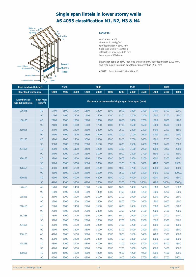
SmartLam GL13S Design Guide 24 Aug 2018
EXAMPLE: wind speed = N3 sheet roof - 40 kg/m2
roof load width = 3900 mm floor load width = 1200 mm rafter/truss spacing = 600 mm lintel span = 3500 mm Enter span table at 4500 roof load width column, floor load width 1200 mm, and read down to a span equal to or greater than 3500 mm ADOPT: SmartLam GL13S – 336 x 55
Lintel span
Upper floor load width
Roof load width
Rafter ortruss
spacing
Jamb stud
Common stud
Lowerstorey lintel
Single span lintels in lower storey walls
AS 4055 classification N1, N2, N3 & N4
Roof load width (mm) 1500 3000 4500 6000
Floor load width (mm) 1200 2400 3600 1200 2400 3600 1200 2400 3600 1200 2400 3600
Member size (GL13S) DxB (mm)
Roof mass (kg/m2)
Maximum recommended single span lintel span (mm)
126x55 40 1700 1500 1400 1600 1400 1300 1500 1400 1300 1400 1300 1200
90 1500 1400 1300 1400 1300 1200 1300 1200 1200 1200 1200 1100
168x55 40 2200 2000 1800 2100 1900 1800 2000 1800 1700 1900 1800 1700
90 2100 1900 1800 1900 1700 1600 1700 1600 1600 1600 1600 1500
210x55 40 2700 2500 2300 2600 2400 2200 2500 2300 2200 2400 2200 2100
90 2600 2400 2200 2300 2200 2100 2200 2100 2000 2000 2000 1900
252x55 40 3200 2900 2700 3000 2800 2700 2900 2700 2600 2800 2700 2500
90 3000 2800 2700 2800 2600 2500 2600 2500 2400 2500 2400 2300
294x55 40 3500 3300 3100 3400 3200 3000 3300 3100 2900 3200 3000 2900
90 3400 3200 3000 3100 3000 2800 3000 2800 2700 2800 2700 2600
336x55 40 3900 3600 3400 3800 3500 3300 3600 3400 3200 3500 3300 3200
90 3700 3500 3300 3500 3300 3100 3300 3100 3000 3100 3000 29005
378x55 40 4300 4000 3700 4100 3800 3600 4000 3700 3500 3800 3600 3500
90 4100 3800 3600 3800 3600 3400 3600 3400 3300 3400 3300 320010
420x55 40 4600 4300 4000 4400 4200 3900 4300 4000 3800 4200 3900 3800
90 4400 4100 3900 4100 3900 3700 3900 3700 360010 3700 360010 350015
126x65 40 1700 1600 1400 1600 1500 1400 1600 1400 1400 1500 1400 1300
90 1600 1500 1400 1500 1400 1300 1400 1300 1200 1300 1200 1200
168x65 40 2300 2100 1900 2200 2000 1900 2100 1900 1800 2000 1900 1800
90 2200 2000 1900 2000 1800 1700 1800 1700 1600 1700 1600 1600
210x65 40 2900 2600 2400 2700 2500 2400 2600 2400 2300 2500 2400 2200
90 2700 2500 2300 2500 2300 2200 2300 2200 2100 2200 2100 2000
252x65 40 3300 3000 2900 3100 2900 2800 3000 2900 2700 2900 2800 2700
90 3100 2900 2800 2900 2800 2600 2700 2600 2500 2600 2500 2400
294x65 40 3700 3400 3200 3500 3300 3100 3400 3200 3100 3300 3100 3000
90 3500 3300 3100 3300 3100 3000 3100 3000 2800 2900 2800 2800
336x65 40 4100 3800 3500 3900 3700 3500 3800 3600 3400 3700 3500 3300
90 3900 3600 3400 3600 3400 3300 3400 3300 3200 3300 3100 3000
378x65 40 4500 4100 3900 4300 4000 3800 4100 3900 3700 4000 3800 3600
90 4200 4000 3800 3900 3700 3600 3700 3600 3400 3600 3400 3300
420x65 40 4800 4500 4200 4600 4300 4100 4500 4200 4000 4300 4100 3900
90 4600 4300 4100 4300 4100 3900 4000 3900 3700 3900 3700 36005

SmartLam GL13S Design Guide 25 Aug 2018
Single span lintels in lower storey walls
AS 4055 classification N1, N2, N3 & N4 (Cont’d)
Roof load width (mm) 1500 3000 4500 6000
Floor load width (mm) 1200 2400 3600 1200 2400 3600 1200 2400 3600 1200 2400 3600
Member size (GL13S) DxB (mm)
Roof mass (kg/m2)
Maximum recommended single span lintel span (mm)
126x85 40 1900 1700 1600 1800 1600 1500 1700 1600 1500 1600 1500 1400
90 1800 1600 1500 1600 1500 1400 1500 1400 1300 1400 1300 1300
168x85 40 2600 2300 2100 2400 2200 2100 2300 2100 2000 2200 2100 1900
90 2400 2200 2000 2200 2000 1900 2000 1900 1800 1900 1800 1700
210x85 40 3100 2800 2700 2900 2700 2600 2800 2700 2500 2700 2600 2400
90 2900 2700 2600 2700 2500 2400 2500 2400 2300 2400 2300 2200
252x85 40 3500 3200 3100 3400 3100 3000 3200 3100 2900 3100 3000 2800
90 3300 3100 3000 3100 2900 2800 2900 2800 2700 2800 2700 2600
294x85 40 3900 3600 3400 3800 3500 3300 3600 3400 3300 3500 3400 3200
90 3700 3500 3300 3500 3300 3200 3300 3200 3000 3100 3000 2900
336x85 40 4400 4000 3800 4200 3900 3700 4000 3800 3600 3900 3700 3500
90 4100 3900 3700 3900 3700 3500 3600 3500 3400 3500 3400 3300
378x85 40 4800 4400 4100 4600 4300 4000 4400 4200 4000 4300 4100 3900
90 4500 4200 4000 4200 4000 3800 4000 3800 3700 3800 3700 3600
420x85 40 5100 4800 4500 4900 4600 4400 4800 4500 4300 4600 4400 4200
90 4900 4600 4400 4600 4300 4200 4300 4100 4000 4100 4000 3900
NOTES: 1. D = member depth, B = member breadth, NS = not suitable.
2. Total upper floor mass of 40 kg/m2, floor live load of 1.5 kPa, floor point load of 1.8 kN.
3. Minimum bearing length = 35 mm at end supports. Subscript values indicate the minimum additional bearing length where required to be greater than 35 mm.
4. Restraint value for slenderness calculations is 600 mm.
5. Not all sizes of SmartLam GL13S in this table are stocked in each state. Please check with your supplier before ordering

SmartLam GL13S Design Guide 26 Aug 2018
EXAMPLE:
wind speed = N3 sheet roof - 40 kg/m2 rafter spacing = 600 rafter span (Ssingle span) = 5800 mm Enter span table at rafter spacing of 600 mm, and read down to a span equal to or greater than 5800 mm for a 40 kg/m2 roof ADOPT: SmartLam GL13S –210 x 55
Overhang
Rafterspacing
Maximum Birdsmouth = 30% of rafter depth
Rafter span
Propped ridgeboard
Rafter
Single/continuous span roof rafter with ceiling attached -
AS 4055 classification N1, N2, N3 & N4
Rafter spacing (mm) 450 600 900 1200 450 600 900 1200
Member size (GL13S) DxB (mm)
Roof mass (kg/m2)
Maximum recommended rafter span (mm)
Single Span Continuous Span
126x55 30 4200 4100 3600 3300 5300 5300 5000 4500
40 4100 3800 3300 3000 5300 5100 4500 4200
75 3400 3100 2700 2500 4600 4200 3700 3400
90 3200 2900 2600 2300 4400 4000 3500 3200
168x55 30 5800 5400 4800 4400 7300 6900 6400 6000
40 5400 5000 4400 4100 6900 6500 6000 5500
75 4500 4100 3600 3300 6100 5600 5000 4500
90 4300 3900 3400 3100 5800 5300 4700 4300
210x55 30 6800 6400 5900 5500 8500 8100 7500 7000
40 6400 6100 5500 5000 8100 7700 7100 6600
75 5600 5100 4600 4200 7100 6700 6100 5700
90 5300 4900 4300 3900 6900 6400 5800 5300
252x55 30 7600 7300 6800 6400 9600 9200 8500 8000
40 7300 6900 6400 6000 9200 8700 8000 7500
75 6500 6100 5400 5000 8200 7600 7000 6600
90 6200 5800 5200 4700 7800 7400 6700 6300
294x55 30 8500 8100 7500 7100 10700 10200 9500 8900
40 8100 7700 7100 6700 10200 9700 9000 8400
75 7200 6800 6200 5800 9100 8500 7800 7300
90 6900 6500 6000 5500 8800 8200 7500 70005
336x55 30 9200 8800 8200 7800 11600 11100 10400 9800
40 8900 8400 7800 7400 11100 10600 9800 9300
75 7900 7500 6900 6400 10000 9400 8600 81005
90 7600 7200 6600 6200 9600 9000 8300 780010
378x55 30 10000 9600 8900 8500 12000 12000 11200 107005
40 9600 9100 8500 8000 12000 11500 10700 101005
75 8600 8100 7500 7000 10800 10200 9400 880010
90 8300 7800 7200 6700 10400 9800 90005 850015
420x55 30 10600 10200 9600 9100 12000 12000 12000 1150010
40 10300 9800 9100 8600 12000 12000 11500 1080010
75 9300 8700 8100 7600 11600 11000 101005 950015
90 8900 8400 7800 7300 11200 10600 980010 910020
126x65 30 4500 4300 3800 3500 5800 5800 5200 4800
40 4300 4000 3500 3200 5800 5400 4800 4400
75 3600 3300 2900 2600 4900 4500 3900 3600
90 3400 3100 2700 2500 4600 4200 3700 3400
168x65 30 6000 5600 5000 4600 7600 7200 6600 6200
40 5600 5200 4600 4300 7200 6800 6200 5800
75 4700 4400 3800 3500 6300 5900 5200 4800
90 4500 4100 3600 3300 6100 5600 5000 4500
210x65 30 7000 6600 6100 5800 8800 8300 7700 7300
40 6600 6300 5800 5300 8400 7900 7300 6900
75 5900 5400 4800 4400 7400 7000 6400 6000
90 5600 5100 4500 4100 7100 6700 6100 5600
252x65 30 7800 7500 7000 6600 9900 9400 8800 8300
40 7500 7100 6600 6200 9500 9000 8300 7800
75 6700 6300 5700 5300 8400 7900 7300 6800
90 6400 6100 5400 5000 8100 7600 7000 6500

SmartLam GL13S Design Guide 27 Aug 2018
Single/continuous span roof rafter with ceiling attached
- AS 4055 classification N1, N2, N3 & N4 (Cont’d)
Rafter spacing (mm) 450 600 900 1200 450 600 900 1200
Member size (GL13S) DxB (mm)
Roof mass (kg/m2)
Maximum recommended rafter span (mm)
Single Span Continuous Span
294x65 30 8700 8300 7800 7400 10900 10500 9800 9200 40 8300 7900 7400 6900 10500 10000 9300 8700 75 7500 7000 6500 6100 9400 8800 8100 7600 90 7200 6800 6200 5800 9100 8500 7800 7300
336x65 30 9400 9100 8500 8100 11900 11400 10700 10100 40 9100 8700 8100 7600 11400 10900 10100 9600 75 8200 7700 7100 6700 10300 9700 9000 8400 90 7900 7400 6900 6400 10000 9400 8600 81005
378x65 30 10200 9800 9200 8700 12000 12000 11600 11000 40 9800 9400 8700 8300 12000 11800 11000 10400 75 8900 8400 7800 7300 11200 10500 9700 91005 90 8600 8100 7500 7000 10800 10200 9400 880010
420x65 30 10900 10500 9900 9400 12000 12000 12000 11900 40 10500 10100 9400 8900 12000 12000 11900 11200 75 9500 9000 8400 7800 12000 11300 10500 99005 90 9200 8700 8000 7500 11600 11000 101005 950015
126x85 30 4900 4600 4100 3800 6500 6200 5600 5200 40 4600 4300 3800 3500 6200 5800 5200 4800 75 3900 3600 3100 2900 5300 4900 4300 3900 90 3700 3400 3000 2700 5000 4600 4100 3700
168x85 30 6300 6000 5400 5000 7900 7500 7000 6600
40 6000 5600 5000 4600 7500 7100 6600 6200
75 5100 4700 4200 3800 6700 6300 5700 5200
90 4900 4500 4000 3600 6400 6100 5400 4900
210x85 30 7300 6900 6500 6100 9200 8700 8100 7700
40 7000 6600 6100 5700 8800 8300 7700 7300
75 6200 5800 5200 4800 7800 7400 6800 6300
90 6000 5500 4900 4500 7500 7100 6500 6100
252x85 30 8200 7800 7300 7000 10300 9900 9200 8800
40 7900 7500 7000 6600 9900 9400 8700 8300
75 7100 6700 6100 5700 8900 8400 7700 7200
90 6800 6400 5900 5400 8600 8100 7400 7000
294x85 30 9000 8700 8100 7700 11300 10900 10200 9700
40 8700 8300 7700 7300 10900 10400 9700 9200
75 7800 7400 6900 6400 9900 9300 8600 8100
90 7600 7200 6600 6200 9600 9000 8300 7800
336x85 30 9800 9400 8900 8500 12000 11900 11200 10700
40 9500 9100 8500 8000 11900 11400 10600 10100
75 8600 8100 7500 7100 10800 10200 9500 8900
90 8300 7900 7300 6800 10500 9900 9100 8600
378x85 30 10500 10200 9600 9200 12000 12000 12000 11500
40 10200 9800 9200 8700 12000 12000 11500 11000
75 9300 8800 8200 7700 11700 11100 10300 9700
90 9000 8500 7900 7400 11300 10700 9900 9300
420x85 30 11200 10900 10300 9800 12000 12000 12000 12000
40 10900 10500 9800 9400 12000 12000 12000 11800
75 10000 9500 8800 8300 12000 11900 11100 10400 90 9600 9200 8500 8000 12000 11500 10700 101005
NOTES:
1. D = member depth, B = member breadth, NS = not suitable.
2. The above table was based on a batten spacing of 900 mm
3. Maximum birdsmouth depth = 30 % of rafter depth
4. End bearing lengths = 35 mm at end supports and 35 mm at internal supports for continuous members. Subscript values indicate the minimum addi-tional bearing length where required to be greater than 35 mm at end supports and 35 mm at internal supports
5. Construction loads shall not be applied to overhangs until a 190 x 19 (minimum) timber fascia or other fascia of equivalent stiffness is rigidly and per-manently attached to the end of rafter overhangs
6. rafter spacing up to 1200 mm
7. Not all sizes of SmartLam GL13S in this table are stocked in each state. Please check with your supplier before ordering

SmartLam GL13S Design Guide 28 Aug 2018
EXAMPLE: wind speed = C3 sheet roof - 40 kg/m2 rafter/truss spacing = 600 mm rafter span (single span) = 5800 mm Enter span table at rafter spacing of 600 mm, and read down to a span equal to or greater than 5800 mm for a 40 kg/m2 roof ADOPT: SmartLam GL13S - 210 x 55
Single/continuous span roof rafter without ceiling attached
AS 4055 classification N1, N2, N3 & N4
Rafter spacing (mm) 450 600 900 1200 450 600 900 1200
Member size (GL13S) DxB (mm)
Roof mass (kg/m2)
Maximum recommended rafter span (mm)
Single Span Continuous Span
126x55 10 4300 4200 4100 3800 5400 5400 5100 4300
20 4300 4200 4100 3800 5400 5400 5200 4400
40 4100 3800 3400 3100 5400 5200 4600 4200
60 3700 3400 3000 2700 5000 4600 4100 3700
168x55 10 6400 6300 5600 5100 8400 8400 6900 5900
20 6300 6000 5400 5000 7900 7500 7000 6000
40 5400 5000 4500 4100 7000 6600 6100 5600
60 4900 4500 4000 3600 6400 6100 5400 4900
210x55 10 7900 7700 7000 6400 10000 9600 8700 7400
20 7300 6900 6500 6100 9100 8700 8100 7600
40 6500 6100 5500 5100 8200 7700 7100 6700
60 6000 5500 4900 4500 7500 7100 6500 6100
252x55 10 8800 8600 8200 7600 11100 10800 10300 9000
20 8200 7800 7300 7000 10300 9900 9200 8700
40 7300 7000 6400 6000 9200 8700 8100 7600
60 6800 6400 5900 5400 8600 8100 7400 6900
294x55 10 9700 9400 9000 8700 12000 11900 11300 10600
20 9000 8700 8100 7700 11300 10900 10200 9700
40 8200 7700 7200 6700 10300 9700 9000 8500
60 7600 7200 6600 6200 9500 9000 8300 7800
336x55 10 10400 10200 9800 9400 12000 12000 12000 11900
20 9800 9400 8900 8500 12000 11900 11200 10600
40 8900 8500 7900 7400 11200 10600 9900 9300
60 8300 7900 7300 6800 10500 9900 9100 8600
378x55 10 11200 11000 10500 10200 12000 12000 12000 12000
20 10500 10200 9600 9200 12000 12000 12000 115005 40 9600 9200 8500 8100 12000 11500 10700 101005
60 9000 8500 7900 7400 11300 10700 9900 93005
420x55 10 11900 11700 11200 10800 12000 12000 12000 12000
20 11200 10800 10300 9800 12000 12000 12000 120005
40 10300 9800 9200 8700 12000 12000 11500 1090010
60 9700 9200 8500 8000 12000 11500 10700 1000010
126x65 10 4600 4600 4400 4000 5900 5900 5600 4700
20 4700 4600 4300 4000 5900 5900 5700 4800
40 4300 4000 3600 3300 5900 5400 4800 4400
60 3900 3600 3100 2900 5300 4800 4300 3900
168x65 10 6900 6800 5900 5400 8800 8600 7600 6400
20 6400 6200 5700 5300 8100 7700 7200 6600
40 5700 5300 4700 4300 7200 6800 6300 5900
60 5100 4700 4200 3800 6700 6300 5700 5200
210x65 10 8000 7800 7400 6700 10100 9800 9400 8100
20 7500 7100 6700 6300 9300 9000 8400 8000
40 6700 6300 5800 5400 8400 8000 7400 6900
60 6200 5800 5200 4700 7800 7300 6800 6300
252x65 10 9000 8700 8300 8000 11300 11000 10500 9800
20 8400 8000 7500 7200 10500 10100 9500 9000
40 7600 7200 6700 6300 9500 9000 8400 7900
60 7000 6600 6100 5700 8900 8300 7700 7200
Overhang
Rafterspacing
Maximum Birdsmouth = 30% of rafter depth
Rafter span
Propped ridgeboard
Rafter

SmartLam GL13S Design Guide 29 Aug 2018
Single/continuous span roof rafter without ceiling attached
AS 4055 classification N1, N2, N3 & N4 (Cont’d)
Rafter spacing (mm) 450 600 900 1200 450 600 900 1200
Member size (GL13S) DxB (mm)
Roof mass (kg/m2)
Maximum recommended rafter span (mm)
Single Span Continuous Span
294x65 10 9800 9600 9200 8900 12000 12000 11500 11100 20 9200 8900 8300 8000 11500 11100 10500 10000 40 8400 8000 7400 7000 10500 10000 9300 8800 60 7800 7400 6800 6400 9800 9300 8600 8100
336x65 10 10600 10400 10000 9600 12000 12000 12000 12000 20 10000 9600 9100 8700 12000 12000 11500 11000 40 9100 8700 8100 7700 11500 11000 10200 9600 60 8600 8100 7500 7100 10800 10200 9400 8900
378x65 10 11300 11100 10700 10400 12000 12000 12000 12000 20 10700 10400 9800 9400 12000 12000 12000 11900 40 9900 9400 8800 8300 12000 11900 11000 10500 60 9300 8800 8200 7700 11600 11000 10200 9600
420x65 10 12000 11800 11400 11100 12000 12000 12000 12000 20 11400 11100 10500 10100 12000 12000 12000 12000 40 10500 10100 9400 9000 12000 12000 11900 11300 60 9900 9400 8700 8300 12000 11900 11000 104005
126x85 10 5300 5200 4900 4400 6800 6800 6500 5500 20 5300 5100 4600 4300 6800 6700 6200 5600 40 4600 4300 3800 3500 6200 5900 5200 4800 60 4200 3800 3400 3100 5700 5200 4600 4300
168x85 10 7200 7000 6500 5900 9100 8800 8400 7400 20 6700 6400 6000 5600 8400 8100 7600 7200 40 6000 5600 5100 4700 7600 7200 6600 6200 60 5500 5100 4500 4100 7000 6600 6100 5600
210x85 10 8200 8100 7700 7400 10400 10100 9700 9300
20 7700 7400 7000 6700 9700 9300 8800 8400
40 7000 6700 6200 5800 8800 8400 7800 7300
60 6500 6200 5600 5100 8200 7800 7200 6700
252x85 10 9200 8900 8600 8300 11500 11300 10800 10500
20 8600 8300 7900 7500 10800 10500 9900 9500
40 7900 7500 7000 6600 9900 9500 8800 8300
60 7400 7000 6500 6100 9300 8800 8100 7600
294x85 10 10000 9800 9400 9200 12000 12000 11900 11500
20 9500 9200 8700 8300 11900 11500 10900 10500
40 8700 8300 7800 7400 11000 10500 9800 9300
60 8200 7800 7200 6800 10300 9800 9100 8500
336x85 10 10700 10600 10200 9900 12000 12000 12000 12000
20 10200 9900 9500 9100 12000 12000 11900 11400
40 9500 9100 8500 8100 11900 11400 10700 10200
60 8900 8500 7900 7500 11200 10700 9900 9400
378x85 10 11500 11300 11000 10700 12000 12000 12000 12000
20 11000 10700 10200 9800 12000 12000 12000 12000
40 10200 9800 9200 8800 12000 12000 11600 11000
60 9700 9200 8600 8100 12000 11600 10800 10200
420x85 10 12000 12000 11600 11400 12000 12000 12000 12000
20 11600 11400 10900 10500 12000 12000 12000 12000
40 10900 10500 9900 9400 12000 12000 12000 11900
60 10300 9900 9200 8700 12000 12000 11600 11000
395x85 10 11800 11600 11200 11000 12000 12000 12000 12000
20 11200 11000 10500 10100 12000 12000 12000 12000
40 10500 10100 9500 9000 12000 12000 11900 11300
60 9900 9500 8800 8400 12000 11900 11100 10500
425x85 10 12000 12000 11800 11400 12000 12000 12000 12000
20 11800 11400 11000 10600 12000 12000 12000 12000
40 11000 10600 9900 9500 12000 12000 12000 11900
60 10400 10000 9300 8800 12000 12000 11700 11100
NOTES: 1. D = member depth, B = member breadth, NS = not suitable.
2. The above table was based on a batten spacing of 900 mm
3. Maximum birdsmouth depth = 30 % of rafter depth
4. End bearing lengths = 35 mm at end supports and 35 mm at internal supports for continuous members. Subscript values indicate the minimum addi-tional bearing length where required to be greater than 35 mm at end supports and 35 mm at internal supports
5. Construction loads shall not be applied to overhangs until a 190 x 19 (minimum) timber fascia or other fascia of equivalent stiffness is rigidly and perma-nently attached to the end of rafter overhangs
6. Rafter spacing up to 1200 mm
7. Not all sizes of SmartLam GL13S in this table are stocked in each state. Please check with your supplier before ordering

SmartLam GL13S Design Guide 30 Aug 2018
Ridge beamspan
'X' = Rafter Span1
'Y' = Rafter
Span2
Rafter
Roof beam
span
Roof load width
Rafter
Roof Load Width = (X+Y)/2
Roof Load Width = (X+Y)/2
'X'
'Y'
IntermediateRoof beam Ridge beam
EXAMPLE: wind speed = N3 sheet roof - 40 kg/m2 beam span = 4500 mm X = 2000 mm Y = 3000 mm roof load width = (X+Y)/2 = 2500 mm Enter single span table at 3000 roof load width column and read down to span equal to or greater than 4500 mm ADOPT: SmartLam GL13S - 294 x 55
Ridge/Intermediate roof beam
AS 4055 Classification N1, N2, N3 & N4
Roof load width (mm) 1800 3000 4200 5400 6600 7800 1800 3000 4200 5400 6600 7800
Member size (GL13S) DxB
(mm)
Roof mass (kg/m2)
Maximum recommended Ridge/Intermediate beam span (mm)
Single span Continuous span
126x55 40 2600 2200 1900 1700 1600 1500 3600 2800 2300 2000 1800 1600
90 2100 1700 1500 1400 1300 1200 2800 2300 1900 1700 1500 1300
168x55 40 3500 2900 2600 2300 2200 2000 4800 3700 3100 2700 2400 2200
90 2700 2300 2000 1900 1700 1600 3700 3100 2500 2200 2000 18005
210x55 40 4400 3700 3200 2900 2700 2500 6000 4600 3900 3400 3000 280010
90 3400 2900 2600 2300 2200 2000 4700 3800 3200 280010 250020 230030
252x55 40 5200 4400 3900 3500 3200 3000 6800 5500 4600 410010 360015 330025
90 4100 3500 3100 2800 2600 2400 5600 4600 380010 330025 300035 270050
294x55 40 6100 5100 4500 4100 3800 3500 7600 6500 540010 470020 420030 390045
90 4800 4000 3600 3300 3000 2900 6400 530010 450030 390040 350055 320085
336x55 40 6700 5800 5200 4700 4300 4000 8400 74005 620020 540035 480050 440060
90 5500 4600 4100 3800 3500 3300 7000 610025 510040 440060 400090 3600105
378x55 40 7300 6400 5800 5300 4900 4600 9200 810015 690035 610050 550070 500090
90 6100 5200 4600 4200 3900 37005 7700 680035 570060 500090 4500110 4100125
420x55 40 7800 6900 6300 5900 5400 5100 9900 870020 770045 670070 610095 550090
90 6600 5800 5100 4700 4400 410010 83005 730045 630085 5500110 5000130 4500145
126x65 40 2800 2300 2000 1800 1700 1600 3800 3000 2500 2200 2000 1800
90 2200 1800 1600 1500 1400 1300 3000 2500 2100 1800 1600 1500
168x65 40 3700 3100 2700 2500 2300 2100 5100 4000 3400 2900 2600 2400
90 2900 2400 2200 2000 1800 1700 4000 3300 2800 2400 2200 2000
210x65 40 4600 3900 3400 3100 2900 2700 6200 5000 4200 3700 3300 3000
90 3600 3000 2700 2500 2300 2100 4900 4100 3500 3000 270010 250020
252x65 40 5500 4600 4100 3700 3400 3200 7100 6000 5000 4400 400010 360015
90 4400 3700 3300 3000 2800 2600 5900 5000 42005 360015 320030 300040
294x65 40 6300 5400 4800 4300 4000 3700 7900 7000 59005 510015 460025 420035
90 5100 4300 3800 3500 3200 3000 6600 58005 480020 420030 380045 340060
336x65 40 6900 6100 5500 5000 4600 4300 8700 7700 670015 590025 530040 480050
90 5800 4900 4300 4000 3700 3500 7300 650015 550035 480050 430070 390090
378x65 40 7500 6700 6100 5600 5100 4800 9500 84005 750025 660040 590055 540070
90 6400 5500 4900 4500 4100 3900 8000 710025 620045 540070 490095 4400110
SmartLam GL13S Design Guide 31 Aug 2018
Ridge/Intermediate roof beam
AS 4055 Classification N1, N2, N3 & N4 (cont’d)
Roof load width (mm) 1800 3000 4200 5400 6600 7800 1800 3000 4200 5400 6600 7800
Member size (GL13S) DxB
(mm)
Roof mass (kg/m2)
Maximum recommended Ridge/Intermediate beam span (mm)
Single span Continuous span
420x85 40 8600 7600 7000 6500 6200 5800 10800 9600 880015 820035 750050 690065
90 7300 6500 5900 5400 5000 4700 9200 810010 750040 680065 610090 5600105
462x85 40 9200 8200 7500 7000 6600 6300 11500 10300 940020 880045 820065 750090
90 7800 6900 6400 5900 5500 5200 9900 870020 800045 750090 6700105 6200125
126x115 40 3300 2800 2500 2200 2100 1900 4500 3800 3300 2900 2600 2400
90 2600 2200 1900 1800 1600 1500 3600 3000 2700 2400 2100 1900
168x115 40 4400 3700 3300 3000 2800 2600 6000 5100 4400 3900 3500 3200
90 3500 2900 2600 2400 2200 2100 4800 4000 3600 3200 2900 2600
210x115 40 5500 4600 4100 3700 3400 3200 7000 6200 5500 4900 4400 4000
90 4400 3700 3300 3000 2800 2600 5900 5000 4500 4000 3600 3300
252x115 40 6400 5500 4900 4500 4100 3900 8000 7100 6500 5800 5200 4800
90 5200 4400 3900 3600 3300 3100 6800 6000 5300 4800 43005 390010
294x115 40 7100 6300 5700 5200 4800 4500 8900 7900 7300 6800 6100 56005
90 6000 5100 4600 4200 3900 3700 7600 6700 6200 56005 500015 460025
336x115 40 7800 6900 6400 5900 5500 5100 9800 8700 8000 7500 700010 640020
90 6600 5800 5200 4800 4400 4200 8400 7400 6800 640020 570030 520040
378x115 40 8500 7600 6900 6500 6100 5800 10700 9500 8700 81005 770020 720030
90 7200 6400 5900 5400 5000 4700 9100 8100 740010 690030 640040 580055
420x115 40 9100 8200 7500 7000 6600 6300 11400 10200 9400 880010 830030 790040
90 7800 6900 6400 6000 5500 5200 9800 8700 800015 750035 710055 650080
462x115 40 9700 8700 8000 7500 7100 6700 12000 11000 101005 940020 890035 850050
90 8400 7400 6800 6400 6100 5700 10500 9300 860025 800045 760075 710095
210x135 40 5700 4900 4300 3900 3600 3400 7300 6400 5900 5300 4700 4300
90 4600 3900 3400 3100 2900 2700 6200 5300 4700 4300 3900 3500
252x135 40 6600 5800 5200 4700 4400 4100 8300 7400 6700 6300 5700 5200
90 5500 4600 4100 3800 3500 3300 7000 6200 5600 5100 4600 42005
294x135 40 7300 6500 6000 5500 5100 4700 9200 8200 7500 7000 6600 6000
90 6300 5400 4800 4400 4100 3800 7900 7000 6400 6000 540010 490015
336x135 40 8100 7200 6600 6200 5800 5400 10100 9000 8300 7700 7300 690010
90 6900 6100 5500 5000 4700 4400 8700 7700 7100 660010 620020 560030
378x135 40 8700 7800 7200 6700 6300 6000 11000 9800 9100 8400 800010 760020
90 7500 6700 6100 5700 5300 5000 9400 8400 7700 720015 680035 630045
420x135 40 9400 8400 7800 7200 6900 6500 11800 10600 9800 91005 860015 820030
90 8100 7200 6600 6200 5800 5500 10200 9000 83005 780025 740040 700055
462x135 40 10000 9000 8300 7800 7300 7000 12000 11300 10500 980010 920025 880035
90 8700 7700 7100 6600 6300 6000 10900 9700 890015 830035 790050 760085
NOTES:
1. D = member depth, B = member breadth, NS = not suitable.
2. End bearing lengths = 70 mm at end supports and 70 mm at internal supports for continuous members. Subscript values indicate the minimum addi-tional bearing length where required to be greater than 70 mm at end supports and 70 mm at internal supports.
3. rafter spacing up to 1200 mm
4. Not all sizes of SmartLam GL13S in this table are stocked in each state. Please check with your supplier before ordering

SmartLam GL13S Design Guide 32 Aug 2018
EXAMPLE: wind speed = N3 sheet roof - 40 kg/m2
roof load width = 3900 mm rafter/truss spacing = 600 mm verandah span = 3500 mm Enter span table at 4500 roof load width column, rafter spacing of 600 mm, and read down to a span equal to or greater than 3500 mm ADOPT: SmartLam GL13S - 252 x 55
Ve randah beam span
Rafte r or trusse s
Roof load width
Rafte r/truss spacing
Vera ndah Bea m
Single span Verandah beam
AS 4055 Classification N1, N2, N3 & N4
Roof load width (mm) 1500 3000 4500 6000 7500
Rafter/truss spacing (mm) 600 1200 600 1200 600 1200 600 1200 600 1200
Member size (GL13S) DxB
(mm)
Roof mass (kg/m2)
Maximum recommended verandah span (mm)
Single span
126x55 40 2600 2600 2100 2000 1700 1400 1500 1000 1300 NS
90 2000 2000 1600 1500 1400 1200 1200 NS 1100 NS
168x55 40 3500 3400 2800 2800 2400 2200 2000 1800 1800 1400
90 2700 2700 2100 2100 1800 1800 1700 1600 1500 1300
210x55 40 4200 4200 3500 3400 3000 2900 2600 2500 2300 2200
90 3300 3300 2700 2700 2300 2300 2100 2100 1900 1900
252x55 40 4800 4800 4100 4100 3600 3400 3100 3000 2700 2700
90 4000 4000 3200 3200 2800 2800 2500 2500 2300 2300
294x55 40 5400 5400 4600 4600 4200 4100 3600 3500 3200 3100
90 4500 4500 3700 3700 3300 3200 3000 3000 2700 28005
336x55 40 5900 5900 5100 5100 4600 4600 4100 4000 3700 3500
90 4900 4900 4200 4200 3700 3700 3400 3300 3100 310010
378x55 40 6500 6400 5500 5500 5000 5000 4700 4700 420010 4100
90 5400 5400 4600 4500 4100 4100 3800 3800 360015 35005
126x65 40 2700 2800 2200 2200 1900 1600 1600 1200 1400 NS
90 2100 2100 1600 1600 1500 1300 1300 1000 1200 NS
168x65 40 3600 3600 2900 2900 2600 2500 2200 2100 1900 1700
90 2800 2800 2200 2200 1900 1900 1800 1700 1600 1500
210x65 40 4400 4400 3700 3600 3200 3100 2800 2700 2500 2400
90 3500 3500 2800 2800 2400 2500 2200 2200 2100 2000
252x65 40 5000 5000 4300 4300 3900 3800 3400 3200 3000 2900
90 4100 4100 3400 3300 2900 2900 2700 2700 2500 2500
294x65 40 5600 5600 4800 4800 4300 4300 3900 3800 3500 3400
90 4700 4600 3900 3900 3500 3400 3100 3100 2900 2900
336x65 40 6200 6100 5300 5300 4800 4800 4500 4500 4000 3900
90 5100 5100 4400 4300 3900 3900 3600 3500 3300 3300
378x65 40 6700 6700 5800 5700 5200 5200 4900 4900 4600 4500
90 5600 5600 4800 4700 4300 4300 4000 4000 38005 3700
420x65 40 7200 7200 6200 6200 5700 5600 5300 5300 50005 500015
90 6100 6000 5100 5100 4700 4600 4300 43005 41005 4100

SmartLam GL13S Design Guide 33 Aug 2018
Single span Verandah beam
AS 4055 Classification N1, N2, N3 & N4 (Cont’d)
Roof load width (mm) 1500 3000 4500 6000 7500
Rafter/truss spacing (mm) 600 1200 600 1200 600 1200 600 1200 600 1200
Member size (GL13S) DxB
(mm)
Roof mass (kg/m2)
Maximum recommended verandah span (mm)
Single span
126x85 40 3000 3000 2400 2500 2100 2100 1800 1600 1600 1300
90 2300 2300 1800 1800 1600 1500 1400 1300 1400 1100
168x85 40 4000 3900 3200 3200 2800 2800 2600 2500 2300 2200
90 3100 3000 2400 2500 2100 2100 1900 1900 1800 1800
210x85 40 4600 4600 4000 4000 3500 3500 3200 3100 2800 2800
90 3800 3800 3100 3000 2700 2700 2400 2400 2300 2200
252x85 40 5300 5300 4600 4500 4100 4100 3800 3700 3500 3300
90 4400 4400 3700 3600 3200 3200 2900 2900 2700 2800
294x85 40 5900 5900 5100 5100 4600 4600 4300 4300 4000 3900
90 5000 5000 4200 4200 3800 3700 3400 3400 3200 3100
336x85 40 6500 6500 5600 5600 5100 5100 4800 4800 4500 4500
90 5500 5500 4700 4600 4200 4200 3900 3900 3600 3600
378x85 40 7100 7000 6100 6100 5600 5600 5200 5200 5000 4900
90 6000 5900 5100 5100 4600 4600 4300 4300 4100 4100
420x85 40 7600 7600 6600 6600 6000 6000 5600 5600 5400 5300
90 6400 6400 5500 5500 5000 5000 4700 4600 4400 4400
126x115 40 3300 3200 2600 2700 2300 2300 2100 2100 1900 1700
90 2500 2600 2000 2000 1700 1700 1600 1500 1500 1300
168x115 40 4200 4200 3500 3500 3100 3100 2800 2800 2600 2600
90 3400 3300 2700 2700 2400 2400 2100 2100 2000 2000
210x115 40 5000 5000 4300 4300 3900 3800 3500 3500 3300 3200
90 4100 4100 3400 3300 3000 3000 2700 2700 2500 2500
252x115 40 5600 5600 4900 4900 4400 4400 4100 4100 3900 3900
90 4700 4700 4000 4000 3600 3500 3200 3200 3000 3000
294x115 40 6300 6300 5400 5400 5000 5000 4700 4600 4400 4400
90 5300 5300 4500 4500 4100 4100 3800 3700 3500 3500
336x115 40 6900 6900 6000 6000 5500 5500 5100 5100 4900 4900
90 5900 5800 5000 5000 4500 4500 4200 4200 4000 4000
378x115 40 7500 7400 6500 6500 6000 6000 5600 5600 5300 5300
90 6400 6300 5400 5400 5000 4900 4600 4600 4400 4400
420x115 40 8000 8000 7000 7000 6400 6400 6000 6000 5800 5700
90 6900 6800 5900 5900 5400 5400 5000 5000 4800 4700
360x115 40 7200 7200 6300 6300 5800 5700 5400 5400 5100 5100
90 6100 6100 5300 5300 4800 4800 4500 4400 4200 4200

SmartLam GL13S Design Guide 34 Aug 2018
Continuous span Verandah beam
AS 4055 Classification N1, N2, N3 & N4
Roof load width (mm) 1500 3000 4500 6000 7500
Rafter/truss spacing (mm) 600 1200 600 1200 600 1200 600 1200 600 1200
Member size (GL13S) DxB
(mm)
Roof mass (kg/m2)
Maximum recommended verandah span (mm)
Continuous span
126x55 40 3100 3100 2200 2100 1700 1700 1500 1300 1400 1000
90 2700 2700 2100 2000 1600 1600 1400 1200 1300 NS
168x55 40 4200 4200 2900 2900 2400 2400 2100 2000 1800 1700
90 3600 3600 2800 2800 2200 2100 1900 1900 170010 16005
210x55 40 5200 5300 3700 3600 3000 3000 26005 270010 230015 220015
90 4400 4300 3500 3400 28005 280010 240020 240020 220030 210025
252x55 40 6000 6000 4400 4400 360010 350010 310025 310020 280035 280035
90 5000 5000 41005 41005 340025 330020 290040 290040 260050 270055
294x55 40 6700 6700 52005 52005 420025 420025 360040 360040 330055 320050
90 5600 5600 470015 470015 400040 390040 340060 330060 300090 300085
336x55 40 7200 7400 600020 590020 480040 480040 420060 420060 370085 360085
90 6200 6200 520025 520030 450055 450055 390090 390090 3500110 3400105
378x55 40 7700 8100 670030 670030 540055 540055 470085 470090 4200105 4200105
90 6700 6700 570035 570040 510085 510085 4400110 4400110 3900130 3900130
126x65 40 3400 3300 2400 2500 1900 1900 1600 1600 1500 1300
90 2800 2800 2200 2200 1800 1800 1600 1500 1400 1100
168x65 40 4600 4500 3200 3200 2600 2700 2200 2100 2000 1900
90 3800 3800 3000 3000 2400 2600 2100 2000 1900 1800
210x65 40 5500 5500 4000 4000 3300 3200 2800 2800 250010 260010
90 4500 4500 3800 3700 3100 3000 270015 270015 230025 230020
252x65 40 6200 6200 4800 4800 39005 39005 340015 330015 300025 300025
90 5200 5200 4400 4400 370015 360015 320030 320030 280040 280045
294x65 40 6900 7000 5600 5600 460015 450015 400030 400030 360045 350040
90 5800 5800 49005 49005 430030 430030 370045 360045 330065 330065
336x65 40 7400 7700 640010 640010 530030 530030 460050 450045 410065 400065
90 6400 6400 540015 540015 490045 490045 420070 430075 380095 370095
378x65 40 8000 8400 700020 720020 590045 590045 510065 510065 460090 450095
90 6900 7000 600025 600025 540060 540060 480095 470095 4300115 4300115
420x65 40 8400 9000 750025 770030 660060 660060 570090 570090 5100110 5100110
90 7300 7500 640030 640030 580085 580085 5300115 5300115 4800135 4700135
126x85 40 3900 3900 2700 2800 2200 2200 1900 1900 1700 1700
90 3100 3100 2500 2500 2100 2000 1800 1700 1600 1600
168x85 40 4900 5000 3700 3600 3000 3000 2600 2600 2300 2200
90 4100 4100 3300 3300 2800 2800 2400 2600 2200 2000
210x85 40 5800 5800 4600 4500 3800 3700 3200 3200 2900 2900
90 4800 4900 4100 4100 3500 3400 3000 3000 270010 270015
252x85 40 6600 6600 5500 5500 4500 4500 39005 38005 350015 340010
90 5500 5500 4700 4700 42005 42005 360015 360015 330030 320025
294x85 40 7200 7400 6300 6300 53005 53005 460020 450015 410030 400030
90 6200 6200 5300 5300 480015 480015 420030 430035 380045 370045

SmartLam GL13S Design Guide 35 Aug 2018
Continuous span Verandah beam
AS 4055 Classification N1, N2, N3 & N4
Roof load width (mm) 1500 3000 4500 6000 7500
Rafter/truss spacing (mm) 600 1200 600 1200 600 1200 600 1200 600 1200
Member size (GL13S) DxB
(mm)
Roof mass (kg/m2)
Maximum recommended verandah span (mm)
Continuous span
336x85 40 7800 8100 6900 7000 600015 600015 520030 520030 470045 460040
90 6700 6800 5800 5800 530025 530025 490050 480045 430065 440070
378x85 40 8300 8800 7400 76005 680030 680030 590045 580045 520060 520060
90 7200 7400 63005 63005 570035 580035 540065 540065 490095 480090
420x85 40 8900 9500 79005 820010 730040 750040 650060 650060 580085 580085
90 7700 8000 680010 680010 620045 620045 580085 580085 5400110 5400110
126x115 40 4300 4300 3200 3200 2600 2700 2200 2200 2000 1900
90 3400 3400 2700 2700 2400 2400 2100 2000 1800 1800
168x115 40 5300 5300 4300 4300 3500 3400 3000 3000 2700 2700
90 4400 4400 3600 3600 3200 3100 2800 2800 2500 2600
210x115 40 6200 6200 5300 5300 4400 4400 3800 3700 3400 3300
90 5200 5200 4400 4400 4000 4000 3500 3500 3200 3100
252x115 40 6900 7000 6100 6100 5200 5300 4500 4500 4000 4000
90 5900 5900 5000 5100 4600 4600 42005 42005 380015 370010
294x115 40 7500 7800 6700 6800 6100 6100 53005 53005 480015 470015
90 6600 6600 5700 5700 5100 5200 480015 480015 440025 440025
336x115 40 8100 8600 7300 7500 6800 6800 610015 600015 540025 540025
90 7100 7300 6200 6200 57005 57005 530025 530025 500040 500040
378x115 40 8700 9300 7800 8100 730010 740010 680030 680030 610040 600040
90 7600 7900 6700 6800 620010 620010 580035 580035 550055 550055
420x115 40 9300 10000 8300 8800 770015 810020 730035 750040 680055 680055
90 8100 8600 7200 7300 660020 670020 620045 620040 590070 590070
NOTES:
1. D = member depth, B = member breadth, NS = not suitable. 2. End bearing lengths = 35 mm at end supports and 70 mm at internal supports for continuous members. Subscript values indicate the minimum addition-
al bearing length where required to be greater than 35 mm at end supports and 70 mm at internal supports. 3. Restraint value for slenderness calculations is 1200 mm 4. Not all sizes of SmartLam GL13S in this table are stocked in each state. Please check with your supplier before ordering

SmartLam GL13S Design Guide 36 Aug 2018
Hip RafterSpan (Actual Length)
RafterSpacing
Rafter
Facia
Hip Rafter
Overhang(Actual Length)
Hip rafter - sheet and tile roof
AS 4055 Classification N1, N2, N3 & N4
EXAMPLE:
wind speed = N3 roof load = 40 kg/m2 (sheet roof) hip rafter span = 4500 mm (single span) rafter spacing = 600 mm Enter column 600 mm rafter spacing and read down to span equal to or greater than 4500 mm for a 40 kg/m2 roof load ADOPT: SmartLam GL13S - 252 x 55
Rafter spacing (mm) 600 1200
Member size
(GL13S)
Roof & ceiling mass (kg/m2)
Maximum recommended rafter span + overhang span (mm)
Span Overhang Span Overhang
126x55 40 2900 450 2900 400
90 2600 400 2600 350
168x55 40 3500 650 3500 600
90 3100 550 3100 450
210x55 40 4000 800 4000 750
90 3500 700 3500 600
252x55 40 4500 900 4500 900
90 4000 800 4000 750
294x55 40 4900 900 4900 900
90 4300 850 4300 850
336x55 40 5300 1050 5300 1050
90 4700 900 4700 900
378x55 40 5700 1100 5700 1100
90 5000 1000 5000 1000
420x55 40 6100 1200 6100 1200
90 5400 1000 5400 1000
126x65 40 3000 500 3000 450
90 2700 450 2700 400
168x65 40 3600 700 3600 650
90 3200 600 3200 550
210x65 40 4100 800 4100 800
90 3700 700 3700 700
252x65 40 4600 900 4600 900
90 4100 800 4100 800
294x65 40 5100 1000 5100 1000
90 4500 900 4500 900
336x65 40 5500 1100 5500 1100
90 4900 900 4900 900
378x65 40 5900 1100 5900 1100
90 5200 1000 5200 1000
420x65 40 6300 1250 6300 1250
90 5500 1100 5500 1100
NOTES:
1. D = member depth, B = member breadth, NS = not suitable.
2. The above table was based on a batten spacing of 900 mm
3. Minimum Backspan = 200 % of overhang
4. Maximum Birdsmouth depth = 30 % of depth
5. End bearing length = 35 at end supports
6. Construction loads shall not be applied to overhangs until a 190 x 1 9 mm (min) timber fascia or other fascia of equivalent stiffness is rigidly and perma-nently attached to the end of rafter overhangs
7. Not all sizes of SmartLam GL13S in this table are stocked in each state. Please check with your supplier before ordering
Rafter spacing (mm) 600 1200
Member size
(GL13S)
Roof & ceiling mass (kg/m2)
Maximum recommended rafter span + overhang span (mm)
Span Overhang Span Overhang
126x85 40 3200 600 3200 600
90 2800 550 2800 500
168x85 40 3800 750 3800 750
90 3400 600 3400 650
210x85 40 4400 800 4400 800
90 3900 700 3900 700
252x85 40 4900 900 4900 900
90 4300 850 4300 850
294x85 40 5400 1000 5400 1000
90 4700 900 4700 900
336x85 40 5800 1150 5800 1150
90 5100 1000 5100 1000
378x85 40 6200 1200 6200 1200
90 5500 1100 5500 1100
420x85 40 6600 1300 6700 1300
90 5800 1150 5800 1150

SmartLam GL13S Design Guide 37 Aug 2018
ceiling mass - 20 kg/m2 EXAMPLE: Wind speed = N3 X = 5000 mm Ceiling load width = X/2 = 5000/2 = 2500 mm Hanging beam span = 4200 mm Enter column at 3000 mm ceiling load width & read down to a span greater than or equal to 4200 mm ADOPT: SmartLam GL13S - 210 x 55
Hanging beam supporting ceiling loads only
AS 4055 Classification N1, N2, N3 & N4
Ceiling load width (mm) 1800 2400 3000 3600 4200 4800
Member size (GL13S) DxB (mm) Maximum recommended Hanging beam span (mm)
126x55 3200 2900 2600 2500 2300 2200
168x55 4100 3800 3500 3300 3100 2900
210x55 4800 4400 4200 4000 3800 3600
252x55 5500 5100 4800 4500 4300 4100
294x55 6100 5700 5300 5100 4800 4600
336x55 6700 6200 5900 5600 5300 5100
378x55 7300 6800 6400 6100 5800 5600
420x55 7800 7300 6900 6600 6300 6000
126x65 3400 3000 2800 2600 2400 2300
168x65 4200 3900 3700 3500 3200 3100
210x65 5000 4600 4300 4100 3900 3800
252x65 5700 5300 5000 4700 4500 4300
294x65 6300 5900 5500 5300 5000 4800
336x65 6900 6500 6100 5800 5600 5300
378x65 7500 7000 6600 6300 6100 5800
420x65 8100 7600 7200 6800 6500 6300
126x85 3600 3300 3000 2800 2700 2500
168x85 4500 4200 3900 3700 3500 3300
210x85 5200 4900 4600 4400 4200 4000
252x85 6000 5600 5300 5000 4800 4600
294x85 6600 6200 5900 5600 5400 5100
336x85 7300 6800 6500 6200 5900 5700
378x85 7900 7400 7000 6700 6400 6200
420x85 8500 8000 7600 7200 6900 6700
Hanging beam
span
'X' = Total of ceilingjoist spans eitherside of Hanging beam
Hanging beam
Ceiling Joist
Ceiling Load Width = 'X' / 2
NOTES:
1. D = member depth, B = member breadth, NS = not suitable.
2. The above table is based upon a maximum ceiling mass of 20 kg/m2
3. End bearing length = 70 at end supports
4. Restraint value for slenderness calculation is 1500 mm
5. Not all sizes of SmartLam GL13S in this table are stocked in each state. Please check with your supplier before ordering

SmartLam GL13S Design Guide 38 Aug 2018
EXAMPLE: wind speed = N3 total of hanging beam SPAN = 6400 mm ceiling load width = ‘X’ / 2 = 6400 / 2 = 3200 mm counter beam span = 4500 mm Enter column at 3600 mm ceiling load width and read down to a span greater than or equal to 4500 mm ADOPT: SmartLam GL13S - 210 x 55
Ceiling mass - 20 kg/m2
Counter beam supporting hanging beam
AS 4055 Classification N1, N2, N3 & N4
Ceiling load width (mm) 600 1800 2400 3000 3600 4200 4800 5400 6600
Member size (GL13S) DxB (mm)
Maximum recommended Counter beam span (mm)
126x55 4800 3600 3300 3100 2900 2800 2700 2600 2400
168x55 5800 4700 4400 4100 3900 3700 3500 3400 3200
210x55 6700 5500 5200 4900 4700 4600 4400 4300 4000
252x55 7500 6300 5900 5600 5400 5200 5100 4900 4700
294x55 8300 7000 6600 6300 6000 5800 5700 5500 5300
336x55 9000 7600 7200 6900 6600 6400 6200 6100 5800
378x55 9700 8300 7800 7500 7200 7000 6800 6600 6300
420x55 10400 8900 8400 8100 7800 7500 7300 7200 6800
126x65 4900 3800 3500 3300 3100 2900 2800 2700 2500
168x65 5900 4900 4600 4300 4100 3900 3700 3600 3400
210x65 6900 5700 5400 5100 4900 4700 4600 4500 4200
252x65 7700 6500 6100 5800 5600 5400 5300 5100 4900
294x65 8500 7200 6800 6500 6300 6100 5900 5700 5500
336x65 9200 7900 7500 7100 6900 6700 6500 6300 6000
378x65 9900 8500 8100 7800 7500 7200 7100 6900 6600
420x65 10600 9200 8700 8300 8000 7800 7600 7400 7100
126x85 5100 4100 3800 3500 3300 3200 3100 2900 2800
168x85 6200 5100 4800 4600 4400 4200 4100 3900 3700
210x85 7100 6000 5700 5400 5200 5000 4900 4800 4500
252x85 8000 6800 6400 6200 5900 5700 5600 5400 5200
294x85 8800 7500 7200 6900 6600 6400 6200 6100 5800
336x85 9500 8200 7800 7500 7300 7000 6900 6700 6400
378x85 10200 8900 8500 8200 7900 7600 7500 7300 7000
420x85 10800 9500 9100 8800 8500 8200 8000 7800 7500
'X' Total o f Han ging be am Spa n
Han ging be am
Rafter
Propp ed
Rid ge beam
Roo f stru t
Co unter Bea m spa n
Counter Beam
Ceiling Load width = X/2
NOTES:
1. D = member depth, B = member breadth, NS = not suitable.
2. The above table is based upon a maximum ceiling mass of 20 kg/m2
3. End bearing length = 70 at end supports
4. Not all sizes of SmartLam GL13S in this table are stocked in each state. Please check with your supplier before ordering

SmartLam GL13S Design Guide 39 Aug 2018
EXAMPLE: wind speed = N3 sheet roof = 40kg/m2 total of underpurlin span ‘A’= 5000 mm total of rafter span ’B’ = 4200 mm roof area supported = (A/2) x (B/2) = (5000/2) x (4200/2) = 5250000 mm2 ( convert to m2) = 5250000/1000000 = 5.25 m2 total of hanging beam span ’X’ = 4500 mm effective beam spacing = ‘X’ / 2 = 4500 / 2 = 2250 mm strutting/counter beam span = 4500 mm Enter column at 3600 mm effective beam spacing, 6m2 roof area sup-ported and read down to a span greater than or equal to 4500 mm ADOPT: SmartLam GL13S - 336 x 55
Ceiling mass - 20 kg/m2
Strutting/counter beam supporting underpurlins & hanging beam
AS 4055 Classification N1, N2, N3 & N4
Effective beam spacing (mm) 1800 3600
Roof area supported (m2) 2 4 6 8 10 12 2 4 6 8 10 12
Member size (GL13S) DxB
(mm)
Roof mass (kg/m2)
Maximum recommended Strutting/Counter beam span (mm)
126x55 40 2500 1900 1200 NS NS NS 2200 1800 1300 NS NS NS
90 2000 1500 1100 NS NS NS 1800 1400 1100 NS NS NS
168x55 40 3500 2900 2300 1700 1300 1100 3100 2700 2300 1700 1300 1100
90 2900 2200 1900 1500 1200 1000 2700 2100 1800 1500 1200 1000
210x55 40 4200 3800 3400 2700 2100 1700 3800 3500 3200 2700 2100 1700
90 3800 3100 2600 2300 1900 1600 3500 2900 2500 2200 1800 1500
252x55 40 4900 4400 4100 3800 3100 2500 4400 4100 3900 3600 3100 2600
90 4400 3800 3400 3000 2700 2300 4100 3600 3200 2900 2600 2200
294x55 40 5600 5100 4700 4400 4200 3500 5000 4700 4400 4200 4000 3500
90 5100 4400 4000 3700 3400 3100 4700 4200 3800 3600 3300 3000
336x55 40 6200 5700 5300 5000 4700 4500 5500 5200 4900 4700 4500 4300
90 5700 5000 4500 4200 3900 3700 5200 4700 4300 4000 3800 3600
378x55 40 6700 6200 5800 5500 5200 5000 6000 5700 5400 5200 5000 4800
90 6200 5500 5000 4700 4400 4100 5700 5200 4800 4500 4300 4100
420x55 40 7300 6800 6400 6000 5800 5500 6500 6200 5900 5700 5500 5300
90 6800 6000 5500 5100 4800 4600 6200 5700 5300 5000 4700 4500
126x65 40 2700 2100 1500 1100 NS NS 2400 2000 1500 1100 NS NS
90 2100 1600 1300 1000 NS NS 2000 1500 1300 1000 NS NS
168x65 40 3700 3100 2700 2000 1600 1300 3300 2900 2600 2000 1600 1300
90 3100 2400 2000 1800 1400 1200 2900 2300 2000 1700 1400 1200
210x65 40 4400 4000 3600 3200 2500 2100 4000 3700 3400 3100 2500 2100
90 4000 3300 2800 2500 2200 1800 3700 3100 2700 2400 2200 1800
252x65 40 5100 4600 4300 4000 3600 3000 4600 4300 4000 3800 3600 3000
90 4600 4000 3600 3200 2900 2700 4300 3800 3500 3100 2800 2600
294x65 40 5800 5300 4900 4600 4400 4100 5200 4900 4600 4400 4200 4000
90 5300 4600 4200 3900 3600 3400 4900 4400 4000 3800 3500 3300
336x65 40 6400 5900 5500 5200 4900 4700 5800 5400 5200 4900 4700 4500
90 5900 5200 4700 4400 4100 3900 5400 4900 4500 4300 4000 3800
378x65 40 7000 6500 6100 5800 5500 5300 6300 6000 5700 5400 5200 5000
90 6500 5800 5300 4900 4600 4400 6000 5400 5000 4700 4500 4300
420x65 40 7500 7000 6700 6300 6000 5800 6800 6500 6200 5900 5700 5500
90 7000 6300 5800 5400 5100 4800 6500 5900 5500 5200 4900 4700
'X' Total of
Hanging beam span
Hanging Beam
Rafter 'A' Total of Underpurlin Spans
'B' Total of
rafter spans
Strutting/counterbeam span
Propped
Ridge beam
Roof Strut
Roof Area
supported
Strutting / Counter Beam
Roof Area supported = A/2xB/2 Counter/Strutting beam spacing = X/2

SmartLam GL13S Design Guide 40 Aug 2018
Ceiling mass - 20 kg/m2
Strutting/counter beam supporting underpurlins & hanging beam
AS 4055 Classification N1, N2, N3 & N4 (cont’d)
Effective beam spacing (mm) 1800 3600
Roof area supported (m2) 2 4 6 8 10 12 2 4 6 8 10 12
Member size (GL13S) DxB
(mm)
Roof mass (kg/m2)
Maximum recommended Strutting/Counter beam span (mm)
126x85 40 2900 2400 2000 1400 1100 NS 2600 2200 2000 1500 1100 NS
90 2400 1800 1500 1300 1000 NS 2200 1800 1500 1300 1000 NS
168x85 40 4000 3500 3100 2600 2100 1700 3600 3200 2900 2600 2100 1700
90 3500 2700 2300 2000 1800 1500 3200 2600 2200 2000 1800 1500
210x85 40 4700 4300 3900 3700 3300 2700 4300 4000 3700 3500 3300 2800
90 4300 3700 3200 2800 2500 2300 4000 3500 3100 2700 2500 2300
252x85 40 5500 5000 4600 4300 4100 3900 4900 4600 4300 4100 3900 3800
90 5000 4300 3900 3600 3300 3100 4600 4100 3800 3500 3200 3000
294x85 40 6100 5700 5300 5000 4700 4500 5500 5200 5000 4700 4500 4400
90 5700 5000 4500 4200 3900 3700 5200 4700 4400 4100 3800 3700
336x85 40 6800 6300 5900 5600 5300 5100 6100 5800 5500 5300 5100 4900
90 6300 5600 5100 4800 4500 4200 5800 5300 4900 4600 4400 4200
378x85 40 7400 6900 6500 6200 5900 5700 6700 6300 6100 5800 5600 5400
90 6900 6200 5700 5300 5000 4800 6300 5800 5400 5100 4900 4600
420x85 40 8000 7500 7100 6800 6500 6300 7200 6900 6600 6400 6200 6000
90 7500 6800 6300 5800 5500 5300 6900 6400 6000 5600 5400 5100
NOTES:
1. D = member depth, B = member breadth, NS = not suitable
2. Minimum bearing length = 70 mm at end supports
3. The above table was based on a maximum ceiling mass of 20 kg/m2
4. Restraint value for slenderness calculations is 1500 mm
5. Not all sizes of SmartLam GL13S in this table are stocked in each state. Please check with your supplier before ordering
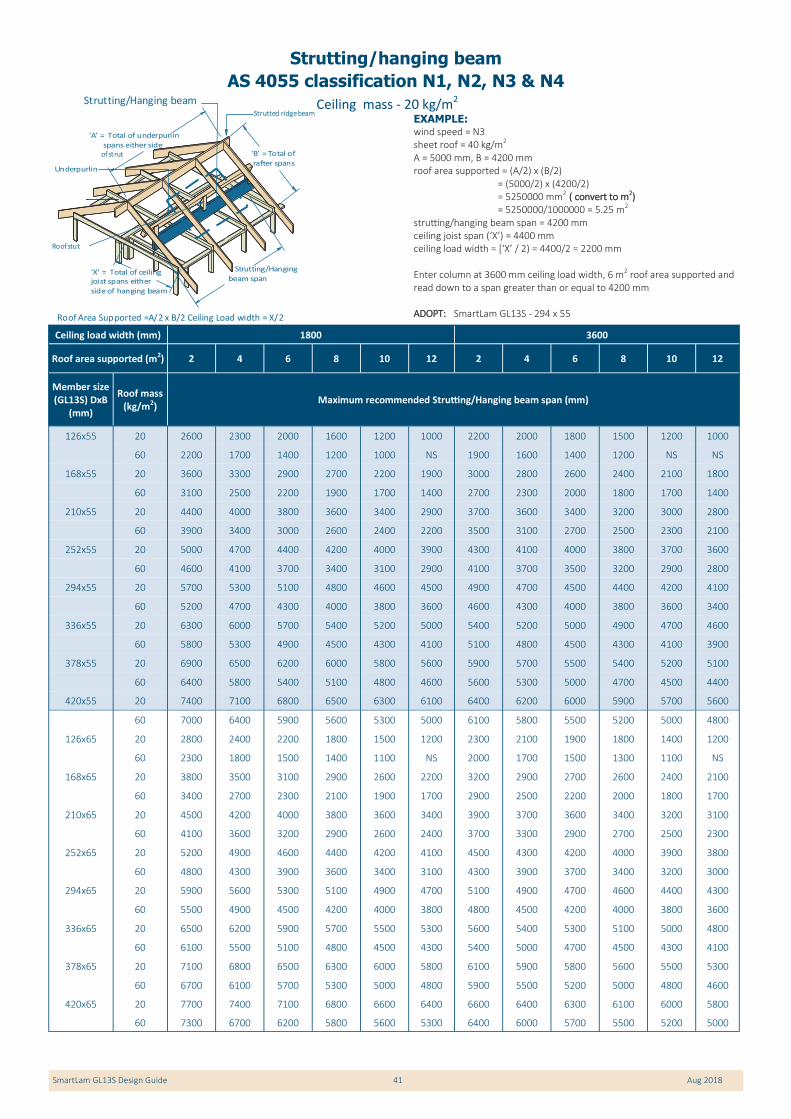
SmartLam GL13S Design Guide 41 Aug 2018
EXAMPLE: wind speed = N3 sheet roof = 40 kg/m2 A = 5000 mm, B = 4200 mm roof area supported = (A/2) x (B/2) = (5000/2) x (4200/2) = 5250000 mm2 ( convert to m2) = 5250000/1000000 = 5.25 m2 strutting/hanging beam span = 4200 mm ceiling joist span (‘X’) = 4400 mm ceiling load width = [‘X’ / 2) = 4400/2 = 2200 mm Enter column at 3600 mm ceiling load width, 6 m2 roof area supported and read down to a span greater than or equal to 4200 mm ADOPT: SmartLam GL13S - 294 x 55
Ceiling mass - 20 kg/m2
Strutting/hanging beam
AS 4055 classification N1, N2, N3 & N4
Ceiling load width (mm) 1800 3600
Roof area supported (m2) 2 4 6 8 10 12 2 4 6 8 10 12
Member size (GL13S) DxB
(mm)
Roof mass (kg/m2)
Maximum recommended Strutting/Hanging beam span (mm)
126x55 20 2600 2300 2000 1600 1200 1000 2200 2000 1800 1500 1200 1000
60 2200 1700 1400 1200 1000 NS 1900 1600 1400 1200 NS NS
168x55 20 3600 3300 2900 2700 2200 1900 3000 2800 2600 2400 2100 1800
60 3100 2500 2200 1900 1700 1400 2700 2300 2000 1800 1700 1400
210x55 20 4400 4000 3800 3600 3400 2900 3700 3600 3400 3200 3000 2800
60 3900 3400 3000 2600 2400 2200 3500 3100 2700 2500 2300 2100
252x55 20 5000 4700 4400 4200 4000 3900 4300 4100 4000 3800 3700 3600
60 4600 4100 3700 3400 3100 2900 4100 3700 3500 3200 2900 2800
294x55 20 5700 5300 5100 4800 4600 4500 4900 4700 4500 4400 4200 4100
60 5200 4700 4300 4000 3800 3600 4600 4300 4000 3800 3600 3400
336x55 20 6300 6000 5700 5400 5200 5000 5400 5200 5000 4900 4700 4600
60 5800 5300 4900 4500 4300 4100 5100 4800 4500 4300 4100 3900
378x55 20 6900 6500 6200 6000 5800 5600 5900 5700 5500 5400 5200 5100
60 6400 5800 5400 5100 4800 4600 5600 5300 5000 4700 4500 4400
420x55 20 7400 7100 6800 6500 6300 6100 6400 6200 6000 5900 5700 5600
60 7000 6400 5900 5600 5300 5000 6100 5800 5500 5200 5000 4800
126x65 20 2800 2400 2200 1800 1500 1200 2300 2100 1900 1800 1400 1200
60 2300 1800 1500 1400 1100 NS 2000 1700 1500 1300 1100 NS
168x65 20 3800 3500 3100 2900 2600 2200 3200 2900 2700 2600 2400 2100
60 3400 2700 2300 2100 1900 1700 2900 2500 2200 2000 1800 1700
210x65 20 4500 4200 4000 3800 3600 3400 3900 3700 3600 3400 3200 3100
60 4100 3600 3200 2900 2600 2400 3700 3300 2900 2700 2500 2300
252x65 20 5200 4900 4600 4400 4200 4100 4500 4300 4200 4000 3900 3800
60 4800 4300 3900 3600 3400 3100 4300 3900 3700 3400 3200 3000
294x65 20 5900 5600 5300 5100 4900 4700 5100 4900 4700 4600 4400 4300
60 5500 4900 4500 4200 4000 3800 4800 4500 4200 4000 3800 3600
336x65 20 6500 6200 5900 5700 5500 5300 5600 5400 5300 5100 5000 4800
60 6100 5500 5100 4800 4500 4300 5400 5000 4700 4500 4300 4100
378x65 20 7100 6800 6500 6300 6000 5800 6100 5900 5800 5600 5500 5300
60 6700 6100 5700 5300 5000 4800 5900 5500 5200 5000 4800 4600
420x65 20 7700 7400 7100 6800 6600 6400 6600 6400 6300 6100 6000 5800
60 7300 6700 6200 5800 5600 5300 6400 6000 5700 5500 5200 5000
'B' = Total of
rafter spans
Strutting/Hanging
beam span
Roof stut
Underpurlin
Strutted ridge beam
Roof Area Supported =A/2 x B/2 Ceiling Load width = X/2
Strutting/Hanging beam
'X' = Total of ceilingjoist spans either
side of hanging beam
'A' = Total of underpurlin
spans either side of strut

SmartLam GL13S Design Guide 42 Aug 2018
Ceiling mass - 20 kg/m2
Strutting/hanging beam
AS 4055 classification N1, N2, N3 & N4 (Cont’d)
Ceiling load width (mm) 1800 3600
Roof area supported (m2) 2 4 6 8 10 12 2 4 6 8 10 12
Member size (GL13S) DxB
(mm)
Roof mass (kg/m2)
Maximum recommended Strutting/Hanging beam span (mm)
126x85 20 3100 2700 2400 2200 1900 1600 2600 2300 2100 2000 1900 1600
60 2600 2100 1800 1500 1400 1200 2300 1900 1700 1500 1400 1200
168x85 20 4100 3800 3500 3200 3000 2800 3500 3300 3000 2900 2700 2600
60 3700 3100 2700 2400 2100 2000 3200 2800 2500 2200 2000 1900
210x85 20 4800 4500 4300 4100 3900 3700 4200 4000 3800 3700 3600 3400
60 4400 3900 3600 3200 3000 2700 3900 3600 3300 3000 2800 2600
252x85 20 5600 5300 5000 4800 4600 4400 4800 4600 4500 4300 4200 4100
60 5200 4600 4200 4000 3700 3500 4600 4200 4000 3700 3600 3400
294x85 20 6300 5900 5700 5400 5200 5000 5400 5200 5000 4900 4800 4600
60 5800 5300 4900 4600 4300 4100 5200 4800 4500 4300 4100 3900
336x85 20 6900 6600 6300 6100 5900 5700 6000 5800 5600 5500 5300 5200
60 6500 5900 5500 5200 4900 4700 5700 5400 5100 4800 4600 4500
378x85 20 7500 7200 6900 6700 6500 6300 6500 6300 6200 6000 5900 5700
60 7100 6500 6100 5700 5500 5200 6300 5900 5600 5400 5100 5000
420x85 20 8100 7800 7500 7300 7100 6900 7000 6900 6700 6500 6400 6300
60 7700 7100 6700 6300 6000 5700 6800 6400 6100 5900 5600 5500
NOTES:
1. D = member depth, B = member breadth, NS = not suitable.
2. The above table was based on a maximum ceiling mass of 20 kg/m2
3. Minimum bearing length = 70 mm at end supports
4. Restraint value for slenderness calculations is 1500 mm
5. Not all sizes of SmartLam GL13S in this table are stocked in each state. Please check with your supplier before ordering

SmartLam GL13S Design Guide 43 Aug 2018
Ceiling mass - 20 kg/m2
Carport Beam(Ridge Perpendicular)
Carport Depth
Centre Beam
Roof Rafters
Ceiling Joist
Underpurlin
Ridge Prop
Ridge Beam
Carport Width
Side Beam
Carport beam - Ridge perpendicular
AS 4055 classification N1, N2, N3 and N4
Member size (GL13S)
DxB (mm)
Roof mass
(kg/m2)
Carport Depth (side)
5200 5400 5600 5800 6000
Maximum recommended carport beam span (mm)
168x65 20 3900 3900 3800 3800 3800
70 3200 3200 3200 3200 3100
210x65 20 4600 4500 4500 4500 4400
70 3800 3800 3800 3700 3700
252x65 20 5200 5200 5100 5100 5100
70 4400 4300 4300 4300 4200
294x65 20 5800 5800 5700 5700 5700
70 4900 4900 4800 4800 4800
336x65 20 6400 6400 6300 6300 6200
70 5400 5400 5300 5300 5200
378x65 20 7000 6900 6900 6800 6800
70 5900 5800 5800 5800 5700
420x65 20 7500 7400 7400 7300 7300
70 6400 6300 6300 6200 6200
168x85 20 4100 4100 4100 4000 4000
70 3500 3400 3400 3400 3300
210x85 20 4900 4800 4800 4700 4700
70 4100 4000 4000 4000 3900
252x85 20 5500 5500 5400 5400 5400
70 4700 4600 4600 4500 4500
294x85 20 6200 6100 6100 6000 6000
70 5200 5200 5100 5100 5100
336x85 20 6800 6700 6700 6600 6600
70 5800 5700 5700 5600 5600
378x85 20 7300 7300 7200 7200 7100
70 6300 6200 6200 6100 6100
420x85 20 7900 7800 7800 7700 7700
70 6800 6700 6600 6600 6500
Member size (GL13S)
DxB (mm)
Roof mass
(kg/m2)
Carport Depth (side)
5200 5400 5600 5800 6000
Maximum recommended carport beam span (mm)
168x115 20 4400 4400 4300 4300 4300
70 3700 3700 3600 3600 3600
210x115 20 5200 5100 5100 5100 5000
70 4400 4300 4300 4300 4200
252x115 20 5900 5800 5800 5700 5700
70 5000 4900 4900 4900 4800
294x115 20 6500 6500 6400 6400 6300
70 5600 5500 5500 5400 5400
336x115 20 7100 7100 7000 7000 7000
70 6100 6100 6000 6000 5900
378x115 20 7700 7700 7600 7600 7500
70 6700 6600 6600 6500 6500
420x115 20 8300 8200 8200 8100 8100
70 7200 7100 7100 7000 7000
168x135 20 4600 4500 4500 4500 4400
70 3800 3800 3800 3800 3700
210x135 20 5300 5300 5300 5200 5200
70 4500 4500 4500 4400 4400
252x135 20 6000 6000 6000 5900 5900
70 5200 5100 5100 5000 5000
294x135 20 6700 6700 6600 6600 6500
70 5800 5700 5700 5600 5600
336x135 20 7300 7300 7200 7200 7200
70 6300 6300 6200 6200 6200
378x135 20 7900 7900 7800 7800 7700
70 6900 6800 6800 6700 6700
420x135 20 8500 8400 8400 8300 8300
70 7400 7400 7300 7200 7200
EXAMPLE: wind speed = N3 sheet roof - 20 kg/m2
Carport side depth 5300 mm Carport beam span 4800 mm Enter span table at carport depth of 5400 mm, and read down to a span equal to or greater than 4800 mm for a 20 kg/m2 roof ADOPT: SmartLam GL13S - 252 x 65
NOTES:
1. D = member depth, B = member breadth, NS = not suitable.
2. The above table was based on a maximum ceiling mass of 20 kg/m2
3. Minimum bearing length = 70 mm at end supports
4. Restraint value for slenderness calculations is 1500 mm
5. Not all sizes of SmartLam GL13S in this table are stocked in each state. Please check with your supplier before ordering

SmartLam GL13S Design Guide 44 Aug 2018
Ceiling mass - 20 kg/m2
Carport beam - Hip and Dutch Gable over opening
AS 4055 classification N1, N2, N3 and N4
Member size (GL13S)
DxB (mm)
Roof mass
(kg/m2)
Carport Depth (side)
5200 5400 5600 5800 6000
Maximum recommended carport beam span (mm)
168x65 20 4100 4100 4000 4000 4000
70 3500 3500 3500 3500 3400
210x65 20 4800 4800 4700 4700 4700
70 4200 4100 4100 4100 4000
252x65 20 5500 5400 5400 5300 5300
70 4800 4700 4700 4700 4600
294x65 20 6100 6000 6000 6000 5900
70 5300 5300 5300 5200 5200
336x65 20 6700 6600 6600 6500 6500
70 5900 5800 5800 5700 5700
378x65 20 7300 7200 7200 7100 7100
70 6400 6400 6300 6300 6200
420x65 20 7800 7700 7700 7600 7600
70 6900 6800 6800 6700 6700
168x85 20 4300 4300 4300 4200 4200
70 3800 3700 3700 3700 3700
210x85 20 5100 5000 5000 5000 4900
70 4400 4400 4400 4300 4300
252x85 20 5800 5700 5700 5600 5600
70 5100 5000 5000 5000 4900
294x85 20 6400 6400 6300 6300 6200
70 5700 5600 5600 5500 5500
336x85 20 7000 7000 6900 6900 6800
70 6200 6200 6100 6100 6000
378x85 20 7600 7600 7500 7500 7400
70 6800 6700 6700 6600 6600
420x85 20 8200 8100 8100 8000 8000
70 7300 7200 7200 7100 7100
Member size (GL13S)
DxB (mm)
Roof mass
(kg/m2)
Carport Depth (side)
5200 5400 5600 5800 6000
Maximum recommended carport beam span (mm)
168x115 20 4600 4600 4500 4500 4500
70 4000 4000 4000 3900 3900
210x115 20 5400 5300 5300 5300 5200
70 4700 4700 4700 4600 4600
252x115 20 6100 6100 6000 6000 5900
70 5400 5400 5300 5300 5200
294x115 20 6800 6700 6700 6600 6600
70 6000 6000 5900 5900 5900
336x115 20 7400 7400 7300 7300 7200
70 6600 6600 6500 6500 6400
378x115 20 8000 7900 7900 7900 7800
70 7200 7100 7100 7000 7000
420x115 20 8600 8500 8500 8400 8400
70 7700 7700 7600 7600 7500
168x135 20 4800 4700 4700 4700 4600
70 4200 4200 4100 4100 4100
210x135 20 5500 5500 5500 5400 5400
70 4900 4900 4800 4800 4800
252x135 20 6300 6200 6200 6200 6100
70 5600 5500 5500 5500 5400
294x135 20 7000 6900 6900 6800 6800
70 6200 6200 6100 6100 6000
336x135 20 7600 7500 7500 7500 7400
70 6800 6800 6700 6700 6600
378x135 20 8200 8100 8100 8100 8000
70 7400 7300 7300 7200 7200
420x135 20 8800 8700 8700 8600 8600
70 8000 7900 7800 7800 7700
EXAMPLE: wind speed = N3 sheet roof - 20 kg/m2
Carport side depth 5300 mm Carport beam span 4800 mm Enter span table at carport depth of 5400 mm, and read down to a span equal to or greater than 4800 mm for a 20 kg/m2 roof ADOPT: SmartLam GL13S - 210 x 65 Carport Beam
Dutch GableSide Beam
Roof Rafters
Ceiling Joist
Underpurlin
Carport Depth
Carport Width
Ridge Prop
Ridge Beam
Centre Beam
Dutch gable
Intermediate beam
NOTES:
1. D = member depth, B = member breadth, NS = not suitable.
2. The above table was based on a maximum ceiling mass of 20 kg/m2
3. Minimum bearing length = 70 mm at end supports
4. Restraint value for slenderness calculations is 1500 mm
5. Not all sizes of SmartLam GL13S in this table are stocked in each state. Please check with your supplier before ordering

Head Office
Victoria New South Wales Queensland Western Australia South Australia
31-45 Orchard Street, Kilsyth Vic 3137
109 Kurrajong Avenue, Mt Druitt, NSW 2770
84 Magnesium Drive, Crestmead QLD 4132
10 Cartwright Drive Forrestdale WA 6112
5-9 Woomera Ave Edinburgh SA 5111
email: [email protected] email: [email protected] email: [email protected] email: [email protected] email: [email protected]
Phone +61 3 9725 0222 Phone +61 2 9677 2600 Phone +61 7 3440 5400 Phone +61 8 9399 1609 Phone +61 8 8345 1966
Fax +61 3 9725 3045 Fax +61 2 9677 2500 Fax +61 7 3440 5444 Fax +61 8 9399 1065 Fax +61 8 8345 1977
Design Library Contents Interactive Printable PC
Specifications software
Technical Support
Design Guides (PDF)
Technical Illustrations
Fixing Details
Never before has so much user-friendly computer power you been unleashed into the hands of
building industry professionals to allow the design and detailing of engineered timber products.
This software, in conjunction with the SmartFrame Design Centre and SmartFrame Engineered
Wood products themselves, combines to form the most sophisticated structural timber option
ever available to the Australian market.
The Smart Frame Engineered Timber Solution represents an entirely new and revolutionary con-
cept in the delivery of the 21st century technology and service to the building industry.
Available from:
SMARTSMARTSMARTFRAME Design Library
Sales 1800 33 77 03 Technical support 1300 668 690 © 2018 Tilling Timber Pty Ltd ABN 92 004 621 121 Date of publication August 2018 SmartFrame is a Registered Trademark of Tilling Timber