Embed Size (px)
Citation preview
HAT160
ATS CONTROLLER
USER MANUAL
SMARTGEN (ZHENGZHOU) TECHNOLOGY CO.,LTD.
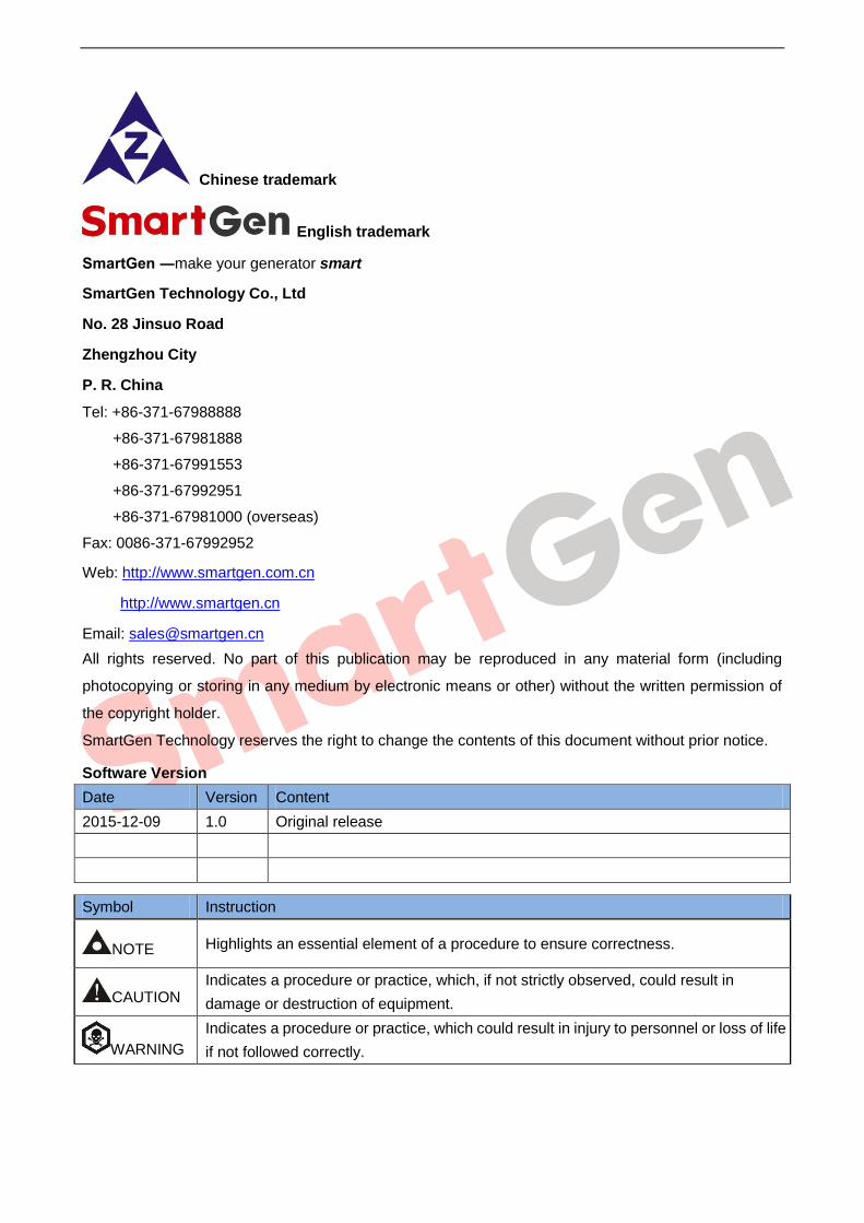
Chinese trademark
English trademark
SmartGen ―make your generator smart
SmartGen Technology Co., Ltd
No. 28 Jinsuo Road
Zhengzhou City
P. R. China
Tel: +86-371-67988888
+86-371-67981888
+86-371-67991553
+86-371-67992951
+86-371-67981000 (overseas)
Fax: 0086-371-67992952
Web: http://www.smartgen.com.cn
http://www.smartgen.cn
Email: [email protected]
All rights reserved. No part of this publication may be reproduced in any material form (including
photocopying or storing in any medium by electronic means or other) without the written permission of
the copyright holder.
SmartGen Technology reserves the right to change the contents of this document without prior notice.
Software Version
Date Version Content
2015-12-09 1.0 Original release
Symbol Instruction
NOTE Highlights an essential element of a procedure to ensure correctness.
CAUTION Indicates a procedure or practice, which, if not strictly observed, could result in
damage or destruction of equipment.
WARNING
Indicates a procedure or practice, which could result in injury to personnel or loss of life
if not followed correctly.
HAT160 ATS CONTROLLER USER MANUAL
HAT160 ATS Controller 2015-12-09 Version 1.0 Page 3 of 17
CONTENTS
1. OVERVIEW ................................................................................................................... 4
2. PERFORMANCE AND CHARACTERISTICS ............................................................... 4
3. SPECIFICATION ........................................................................................................... 5
4. PANEL DESCRIPTION ................................................................................................. 6
4.1 FRONT PANEL ...................................................................................................... 6
4.2 KEY FUNCTION DESCRIPTION ........................................................................... 6
4.3 INDICATOR DESCRIPTION .................................................................................. 7
4.4 OPERATION .......................................................................................................... 7
5. ALARM.......................................................................................................................... 8
5.1 CLOSE/OPEN FAULT ALARM .............................................................................. 8
5.2 EXTERNAL INPUT ALARM ................................................................................... 8
5.3 ALARM RESET ...................................................................................................... 8
6. CONNECTION .............................................................................................................. 9
7. DEFINITION AND RANGE OF PARAMETERS .......................................................... 10
8. PARAMETERS SETTING ........................................................................................... 14
8.1 PARAMETERS SETTING MODE ........................................................................ 14
8.2 PARAMETERS SETTING .................................................................................... 14
8.3 RESET TO DEFAULT .......................................................................................... 14
9. TYPICAL APPLICATION ............................................................................................ 15
10. VERALL DIMENSION AND PANEL CUTOUT ........................................................... 16
10.1 CASE DIMENSION ............................................................................................. 16
10.2 CUTOUT ............................................................................................................. 16
10.3 INSTALLATION .................................................................................................. 17
11. TROBLESHOOTING ................................................................................................... 17
HAT160 ATS CONTROLLER USER MANUAL
HAT160 ATS Controller 2015-12-09 Version 1.0 Page 4 of 17
1. OVERVIEW
HAT160 ATS Controller is suitable for CB ATS of single motor. It can accurately detect 2-way-3-phase
4-wire/single-phase 2-wire voltage and judge voltage abnormal (such as, over voltage, under voltage,
over frequency, under frequency and lack of phase), then control ATS after delay. When ATS switch
abnormally, the controller can detect close/open failure and alarm on the front panel to ensure the
correct action of ATS. After abnormal of I# power, the controller will send signal to start the genset. The
controller has remote communication, remote control and parameter configuration functions via LINK
port communication.
2. PERFORMANCE AND CHARACTERISTICS
HAT160 controller can detect 2-way (2-way mains and 2-way gens or 1-way mains and 1-way gens)
3-phase/single phase voltage and control ATS.
1) Measure and display 2-way 3 phase Voltage and Frequency:
1# 2#
Line voltage (Uab, Ubc, Uca) Line voltage (Uab, Ubc, Uca)
Phase voltage (Ua, Ub, Uc) Phase voltage (Ua, Ub, Uc)
Frequency Hz Frequency Hz
2) Over/under voltage, over/under frequency and loss of phase protection (active or deactive can be
configured);
3) Close/Open failure alarm;
4) LED display work status;
5) Auto/Manual mode. In manual mode, ATS can be switched by pressing front panel button;
6) Applicable for 2 isolated neutral line.
7) “1# Priority, 2# Priority (auto change, auto recovery), No Priority (auto change, manually recovery)”
and “1#/2# power normal/abnormal delay” can be set via panel buttons;
8) Automatic Re-closing;
9) Close delay, delay is 0.5s;
10) Any one way of A phase voltage is normal, the controller and ATS can normally work. When 2-way
power and volts are abnormal at the same time, if any way of A phase voltage is normal, ATS will
automatically transfer to Breaking (Middle) Position;
11) Fire reset interface. When the input port is enabled, ATS will automatically transfer to Breaking
(OFF) Position;
12) Parameter setting: parts of parameters can be adjust from front panel; all can be adjust via LINK
port(with SG72A adaptor) by using computer software;
13) Digitization adjustment of parameters (abandon simulation adjustment, enhanced reliability and
stability);
14) Strong anti-electromagnetic interference ability, can be used under complex electromagnetic
interference environment;
15) Modular design, self extinguishing ABS plastic shell, pluggable terminal, compact structure;
16) Three installation ways: panel built-in, internal 35mm slideway and internal screw mounting.
HAT160 ATS CONTROLLER USER MANUAL
HAT160 ATS Controller 2015-12-09 Version 1.0 Page 5 of 17
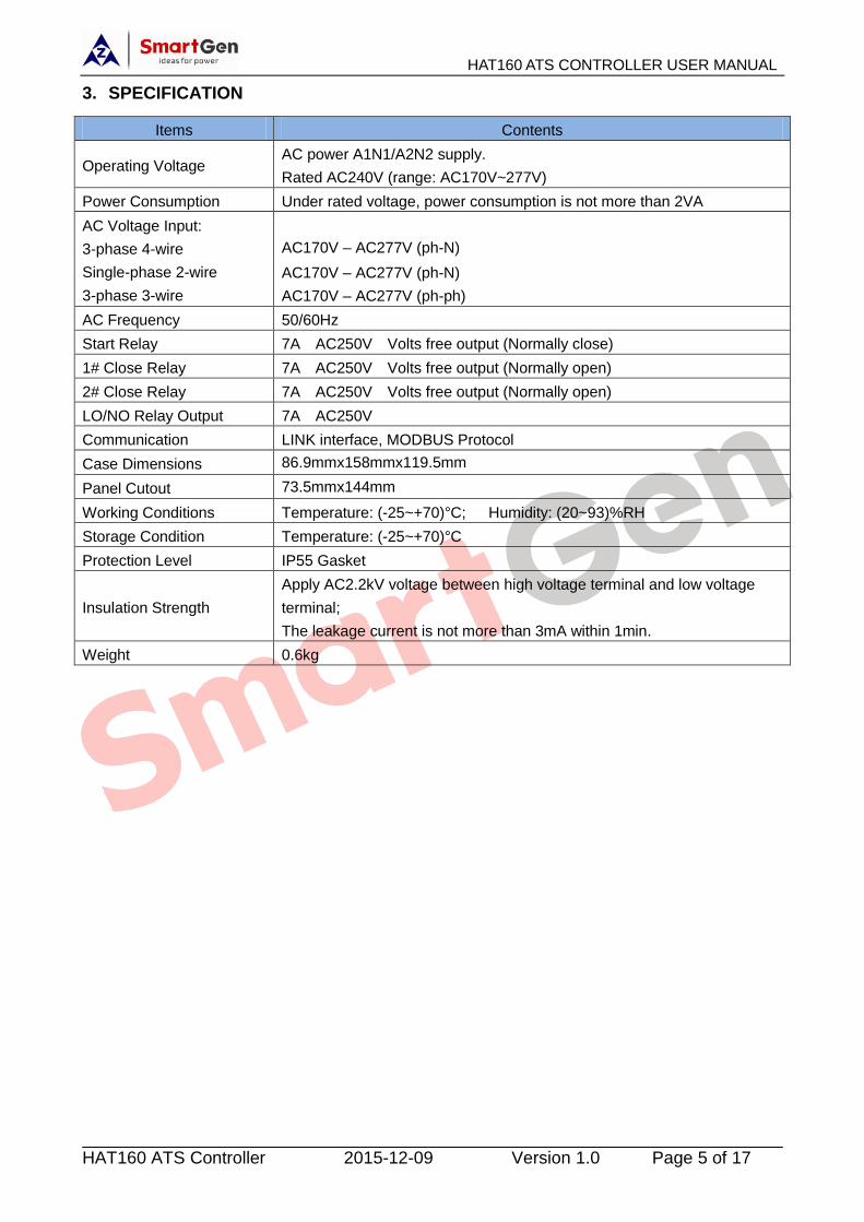
3. SPECIFICATION
Items Contents
Operating Voltage AC power A1N1/A2N2 supply.
Rated AC240V (range: AC170V~277V)
Power Consumption Under rated voltage, power consumption is not more than 2VA
AC Voltage Input:
3-phase 4-wire
Single-phase 2-wire
3-phase 3-wire
AC170V – AC277V (ph-N)
AC170V – AC277V (ph-N)
AC170V – AC277V (ph-ph)
AC Frequency 50/60Hz
Start Relay 7A AC250V Volts free output (Normally close)
1# Close Relay 7A AC250V Volts free output (Normally open)
2# Close Relay 7A AC250V Volts free output (Normally open)
LO/NO Relay Output 7A AC250V
Communication LINK interface, MODBUS Protocol
Case Dimensions 86.9mmx158mmx119.5mm
Panel Cutout 73.5mmx144mm
Working Conditions Temperature: (-25~+70)°C; Humidity: (20~93)%RH
Storage Condition Temperature: (-25~+70)°C
Protection Level IP55 Gasket
Insulation Strength
Apply AC2.2kV voltage between high voltage terminal and low voltage
terminal;
The leakage current is not more than 3mA within 1min.
Weight 0.6kg
HAT160 ATS CONTROLLER USER MANUAL
HAT160 ATS Controller 2015-12-09 Version 1.0 Page 6 of 17
4. PANEL DESCRIPTION
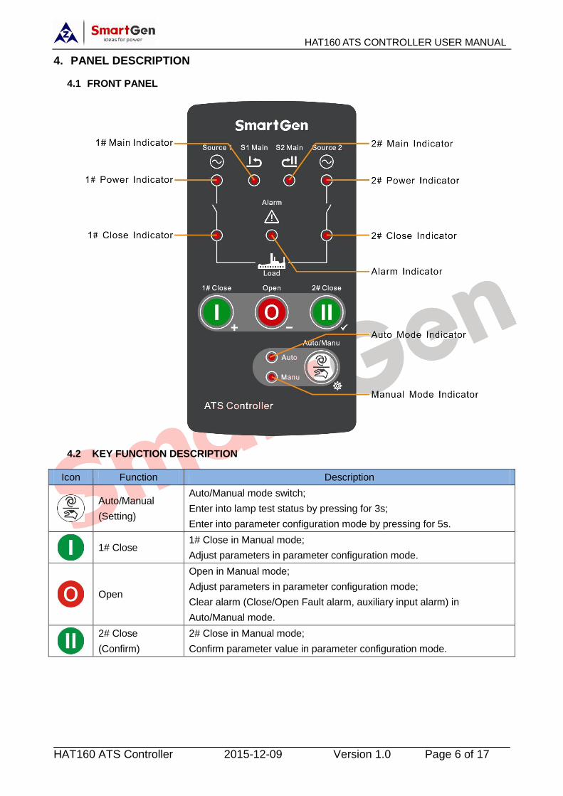
4.1 FRONT PANEL
4.2 KEY FUNCTION DESCRIPTION
Icon Function Description
Auto/Manual
(Setting)
Auto/Manual mode switch;
Enter into lamp test status by pressing for 3s;
Enter into parameter configuration mode by pressing for 5s.
1# Close
1# Close in Manual mode;
Adjust parameters in parameter configuration mode.
Open
Open in Manual mode;
Adjust parameters in parameter configuration mode;
Clear alarm (Close/Open Fault alarm, auxiliary input alarm) in
Auto/Manual mode.
2# Close
(Confirm)
2# Close in Manual mode;
Confirm parameter value in parameter configuration mode.
HAT160 ATS CONTROLLER USER MANUAL
HAT160 ATS Controller 2015-12-09 Version 1.0 Page 7 of 17
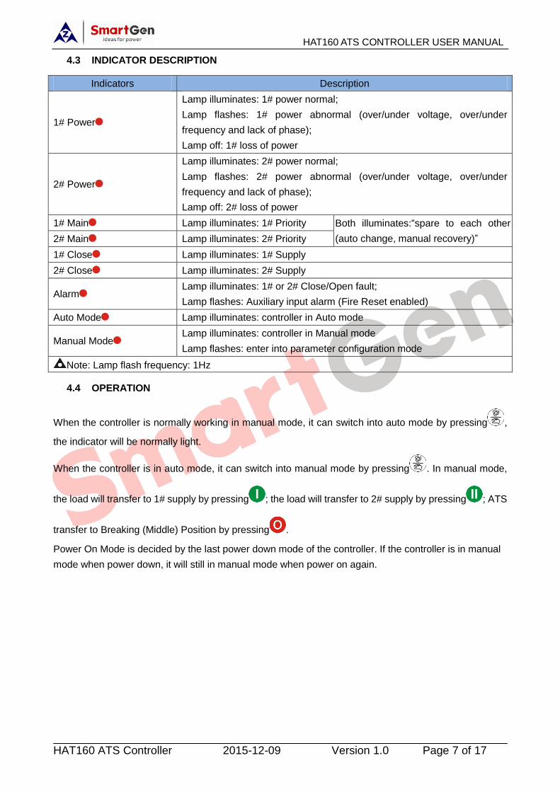
4.3 INDICATOR DESCRIPTION
Indicators Description
1# Power
Lamp illuminates: 1# power normal;
Lamp flashes: 1# power abnormal (over/under voltage, over/under
frequency and lack of phase);
Lamp off: 1# loss of power
2# Power
Lamp illuminates: 2# power normal;
Lamp flashes: 2# power abnormal (over/under voltage, over/under
frequency and lack of phase);
Lamp off: 2# loss of power
1# Main Lamp illuminates: 1# Priority Both illuminates:“spare to each other
(auto change, manual recovery)” 2# Main Lamp illuminates: 2# Priority
1# Close Lamp illuminates: 1# Supply
2# Close Lamp illuminates: 2# Supply
Alarm Lamp illuminates: 1# or 2# Close/Open fault;
Lamp flashes: Auxiliary input alarm (Fire Reset enabled)
Auto Mode Lamp illuminates: controller in Auto mode
Manual Mode Lamp illuminates: controller in Manual mode
Lamp flashes: enter into parameter configuration mode
Note: Lamp flash frequency: 1Hz
4.4 OPERATION
When the controller is normally working in manual mode, it can switch into auto mode by pressing ,
the indicator will be normally light.
When the controller is in auto mode, it can switch into manual mode by pressing . In manual mode,
the load will transfer to 1# supply by pressing ; the load will transfer to 2# supply by pressing ; ATS
transfer to Breaking (Middle) Position by pressing .
Power On Mode is decided by the last power down mode of the controller. If the controller is in manual
mode when power down, it will still in manual mode when power on again.

HAT160 ATS CONTROLLER USER MANUAL
HAT160 ATS Controller 2015-12-09 Version 1.0 Page 8 of 17
5. ALARM
5.1 CLOSE/OPEN FAULT ALARM
In Auto mode, after the controller send a open signal, if the controller can also detect open signal when
open delay ends, it will be regarded as open failure and the alarm indicator illuminates at the same time.
In Auto mode, after the controller send a close signal, if the controller cannot detect close signal when
close delay ends, it will be regarded as close failure and the alarm indicator illuminates at the same time.
a)Close Flow Chart b) Open Flow Chart
5.2 EXTERNAL INPUT ALARM
When auxiliary alarm input signal active is detected, the front panel alarm indicator will flash (1Hz)
meanwhile the ATS transfer to Breaking (Middle) Position and alarm will be locked.
5.3 ALARM RESET
If Close/Open alarms in auto mode, clear alarm by pressing (the indicator will be extinguished at the
same time, the controller will Close/Open again after 3s delay), or switch to manual mode for clearing
alarm by pressing .
If auxiliary input alarms, clear alarm by pressing after the alarm ends and the indicator will be
extinguished at the same time.
Note: trouble already clearing must be confirmed when rest alarm.
Y
N
N
Send Open Signal
Open Signal
Open Singal
Re-open
Open End Open Failure Alarm
Y
Y
N
N
Send Close Signal
Close Signal
Close Singal
Re-close
Close End Close Failure Alarm
Y
HAT160 ATS CONTROLLER USER MANUAL
HAT160 ATS Controller 2015-12-09 Version 1.0 Page 9 of 17
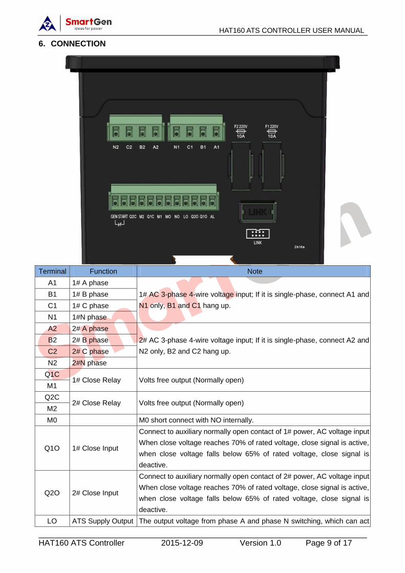
6. CONNECTION
Terminal Function Note
A1 1# A phase
1# AC 3-phase 4-wire voltage input; If it is single-phase, connect A1 and
N1 only, B1 and C1 hang up.
B1 1# B phase
C1 1# C phase
N1 1#N phase
A2 2# A phase
2# AC 3-phase 4-wire voltage input; If it is single-phase, connect A2 and
N2 only, B2 and C2 hang up.
B2 2# B phase
C2 2# C phase
N2 2#N phase
Q1C 1# Close Relay Volts free output (Normally open)
M1
Q2C 2# Close Relay Volts free output (Normally open)
M2
M0 M0 short connect with NO internally.
Q1O 1# Close Input
Connect to auxiliary normally open contact of 1# power, AC voltage input
When close voltage reaches 70% of rated voltage, close signal is active,
when close voltage falls below 65% of rated voltage, close signal is
deactive.
Q2O 2# Close Input
Connect to auxiliary normally open contact of 2# power, AC voltage input
When close voltage reaches 70% of rated voltage, close signal is active,
when close voltage falls below 65% of rated voltage, close signal is
deactive.
LO ATS Supply Output The output voltage from phase A and phase N switching, which can act
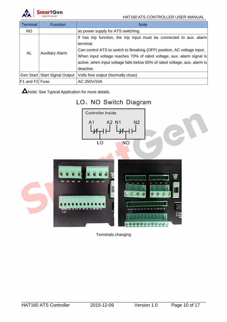
HAT160 ATS CONTROLLER USER MANUAL
HAT160 ATS Controller 2015-12-09 Version 1.0 Page 10 of 17
Terminal Function Note
NO as power supply for ATS switching.
AL Auxiliary Alarm
If has trip function, the trip input must be connected to aux. alarm
terminal.
Can control ATS to switch to Breaking (OFF) position, AC voltage input.
When input voltage reaches 70% of rated voltage, aux. alarm signal is
active, when input voltage falls below 65% of rated voltage, aux. alarm is
deactive.
Gen Start Start Signal Output Volts free output (Normally close)
F1 and F2 Fuse AC 250V/10A
Note: See Typical Application for more details.
Terminals changing
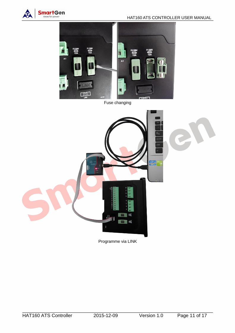
HAT160 ATS CONTROLLER USER MANUAL
HAT160 ATS Controller 2015-12-09 Version 1.0 Page 11 of 17
Fuse changing
Programme via LINK
HAT160 ATS CONTROLLER USER MANUAL
HAT160 ATS Controller 2015-12-09 Version 1.0 Page 12 of 17
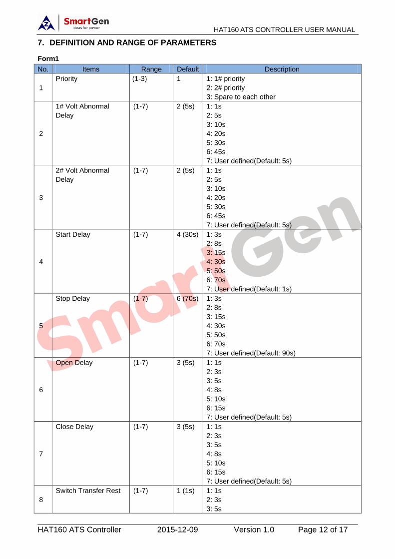
7. DEFINITION AND RANGE OF PARAMETERS
Form1
No. Items Range Default Description
1
Priority (1-3) 1 1: 1# priority
2: 2# priority
3: Spare to each other
2
1# Volt Abnormal
Delay
(1-7) 2 (5s) 1: 1s
2: 5s
3: 10s
4: 20s
5: 30s
6: 45s
7: User defined(Default: 5s)
3
2# Volt Abnormal
Delay
(1-7) 2 (5s) 1: 1s
2: 5s
3: 10s
4: 20s
5: 30s
6: 45s
7: User defined(Default: 5s)
4
Start Delay (1-7) 4 (30s) 1: 3s
2: 8s
3: 15s
4: 30s
5: 50s
6: 70s
7: User defined(Default: 1s)
5
Stop Delay (1-7) 6 (70s) 1: 3s
2: 8s
3: 15s
4: 30s
5: 50s
6: 70s
7: User defined(Default: 90s)
6
Open Delay (1-7) 3 (5s) 1: 1s
2: 3s
3: 5s
4: 8s
5: 10s
6: 15s
7: User defined(Default: 5s)
7
Close Delay (1-7) 3 (5s) 1: 1s
2: 3s
3: 5s
4: 8s
5: 10s
6: 15s
7: User defined(Default: 5s)
8
Switch Transfer Rest (1-7) 1 (1s) 1: 1s
2: 3s
3: 5s

HAT160 ATS CONTROLLER USER MANUAL
HAT160 ATS Controller 2015-12-09 Version 1.0 Page 13 of 17
No. Items Range Default Description
4: 8s
5: 10s
6: 15s
7: User defined(Default: 1s)
9
1# Volt Normal Delay (1-7) 2 (5s) 1: 1s
2: 5s
3: 10s
4: 20s
5: 30s
6: 45s
7: User defined(Default: 5s)
10
2# Volt Normal Delay (1-7) 2 (5s) 1: 1s
2: 5s
3: 10s
4: 20s
5: 30s
6: 45s
7: User defined(Default: 5s)
Note: The parameters in this form can be set via computers and slave.When delay is “7: User
defined”, parameter delay must be set via computer. If parameter is not set via computer, the delay is
Default; if parameter has been set via computer, then the delay is the set value.
Form2
No. Item Range Default Description
1 Power Supply (0-1) 0 0: 3Phase 4Wire
1: 1Phase 2Wire
2 Rated Volt (170-270)V 230
Provide base for over/under volt judge.
Provide base for close volt and aux. alarm
judge.
3 Rated Freq (50.0-60.0)Hz 50.0 Provide base for over/under frequency judge.
4 Over Volt Monitor
Enabled (0-1) 1
0: Disabled
1: Enabled
5 Over Volt Threshold (100-120)% 115 Threshold
6 Over Volt Return (100-120)% 113 Return
7 Under Volt Monitor
Enabled (0-1) 1
0: Disabled
1: Enabled
8 Under Volt Threshold (70-100)% 75 Threshold
9 Under Volt Return (70-100)% 77 Return
10 Over Freq Monitor
Enabled (0-1) 1
0: Disabled
1: Enabled
11 Over Freq Threshold (100-120)% 110 Threshold
12 Over Freq Return (100-120)% 104 Return
13 Under Freq Monitor
Enabled (0-1) 1
0: Disabled
1: Enabled
14 Under Freq Threshold (80-100)% 90 Threshold
15 Under Freq Return (80-100)% 96 Return
16 Loss of Phase Monitor
Enabled (0-1) 1
0: Disabled
1: Enabled (Settled delay: 3s)
Note: The parameters in this form can be set via computers.
HAT160 ATS CONTROLLER USER MANUAL
HAT160 ATS Controller 2015-12-09 Version 1.0 Page 14 of 17
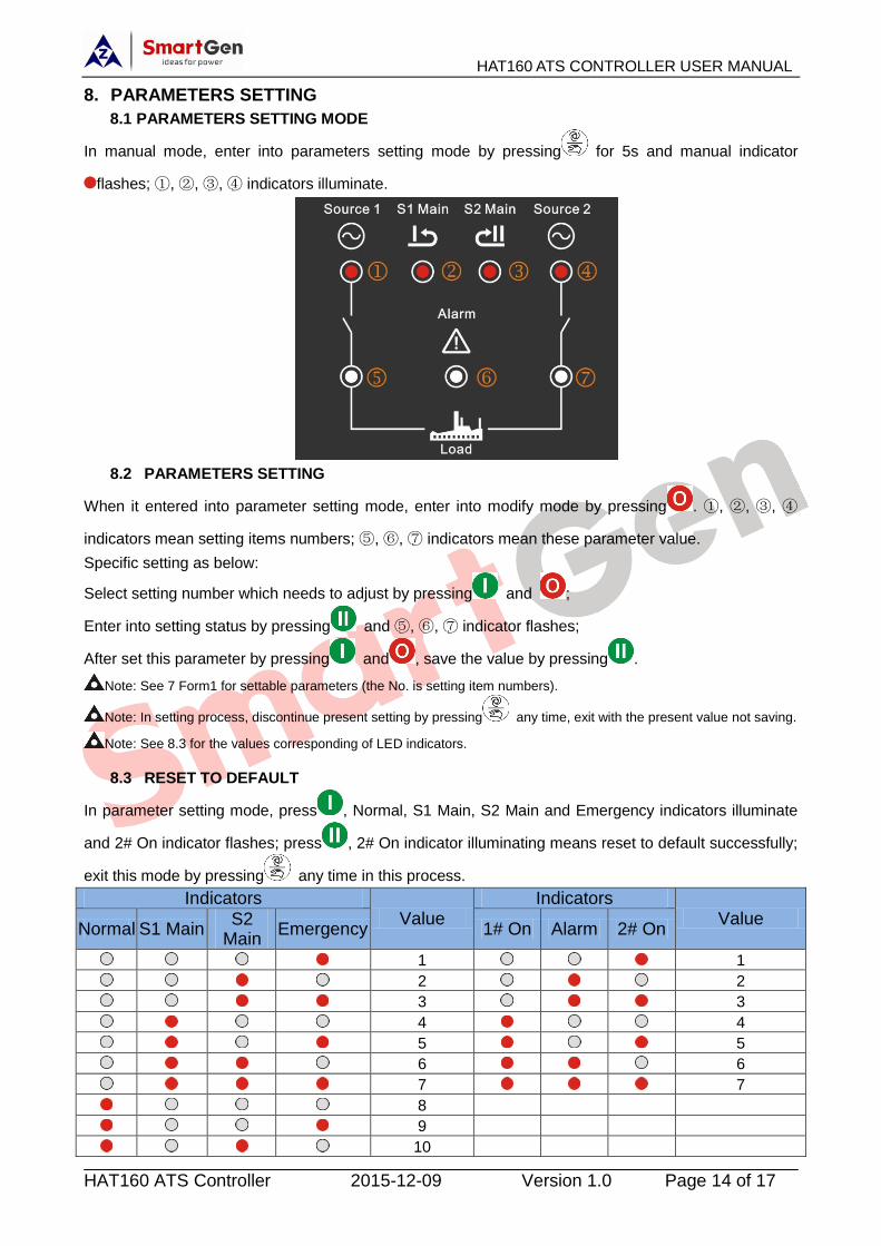
8. PARAMETERS SETTING
8.1 PARAMETERS SETTING MODE
In manual mode, enter into parameters setting mode by pressing for 5s and manual indicator
flashes; ①, ②, ③, ④ indicators illuminate.
8.2 PARAMETERS SETTING
When it entered into parameter setting mode, enter into modify mode by pressing . ①, ②, ③, ④
indicators mean setting items numbers; ⑤, ⑥, ⑦ indicators mean these parameter value.
Specific setting as below:
Select setting number which needs to adjust by pressing and ;
Enter into setting status by pressing and ⑤, ⑥, ⑦ indicator flashes;
After set this parameter by pressing and , save the value by pressing .
Note: See 7 Form1 for settable parameters (the No. is setting item numbers).
Note: In setting process, discontinue present setting by pressing any time, exit with the present value not saving.
Note: See 8.3 for the values corresponding of LED indicators.
8.3 RESET TO DEFAULT
In parameter setting mode, press , Normal, S1 Main, S2 Main and Emergency indicators illuminate
and 2# On indicator flashes; press , 2# On indicator illuminating means reset to default successfully;
exit this mode by pressing any time in this process.
Indicators Value
Indicators Value
Normal S1 Main S2
Main Emergency 1# On Alarm 2# On
1 1
2 2
3 3
4 4
5 5
6 6
7 7
8
9
10

HAT160 ATS CONTROLLER USER MANUAL
HAT160 ATS Controller 2015-12-09 Version 1.0 Page 15 of 17
9. TYPICAL APPLICATION
CAUTION: If ATS has trip function, then it must be connected to AL port (AC Volt input).
Ensure 1# and 2# A phase won’t be abnormal at the same time, otherwise the
controller won’t send Close/Open signal.

HAT160 ATS CONTROLLER USER MANUAL
HAT160 ATS Controller 2015-12-09 Version 1.0 Page 16 of 17
10. VERALL DIMENSION AND PANEL CUTOUT
10.1 CASE DIMENSION
Unit: mm
10.2 CUTOUT
The controller has three installation ways: panel built-in, internal 35mm slideway and internal screw
mounting. Panel built-in and internal screw mounting are as below:
HAT160 ATS CONTROLLER USER MANUAL
HAT160 ATS Controller 2015-12-09 Version 1.0 Page 17 of 17
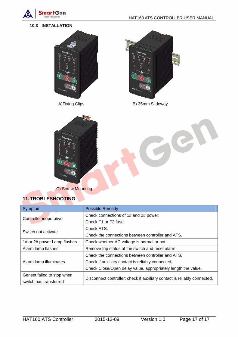
10.3 INSTALLATION
A)Fixing Clips B) 35mm Slideway
C) Screw Mounting
11. TROBLESHOOTING
Symptom Possible Remedy
Controller inoperative Check connections of 1# and 2# power;
Check F1 or F2 fuse
Switch not activate Check ATS;
Check the connections between controller and ATS.
1# or 2# power Lamp flashes Check whether AC voltage is normal or not.
Alarm lamp flashes Remove trip status of the switch and reset alarm.
Alarm lamp illuminates
Check the connections between controller and ATS.
Check if auxiliary contact is reliably connected;
Check Close/Open delay value, appropriately length the value.
Genset failed to stop when
switch has transferred Disconnect controller; check if auxiliary contact is reliably connected.