Embed Size (px)
Citation preview
SmartConnector Installation and
Configuration Guide Buildings Labs

SmartConnector Installation and Configuration Guide
Document : Revision Revision date Page
TDS-M-INSTALLCONFIG-US.BU.N.EN.12.2017.2.30.CC 6 8/14/2018 Page 1 of 92
1 Support.................................................................................................................................................. 6
2 Revision History .................................................................................................................................... 6
3 Overview ............................................................................................................................................... 7
3.1 Scope ............................................................................................................................................. 7
3.2 What is SmartConnector? ............................................................................................................. 7
3.2.1 Processor ............................................................................................................................... 7
3.2.2 Processor Configuration ........................................................................................................ 7
3.2.3 SmartConnector EWS Servers ............................................................................................... 8
3.2.4 REST Endpoints...................................................................................................................... 8
3.2.5 Endpoint Configuration ......................................................................................................... 8
3.2.6 SmartConnector Portal ......................................................................................................... 8
3.2.7 Worker Manager and Workers ............................................................................................. 8
3.2.8 Extension ............................................................................................................................... 8
3.2.9 Persistent Data Store ............................................................................................................ 9
3.2.10 In-Memory Cache .................................................................................................................. 9
3.2.11 Logging .................................................................................................................................. 9
3.2.12 Licensing ................................................................................................................................ 9
4 Installation .......................................................................................................................................... 10
4.1 Prerequisites ............................................................................................................................... 10
4.2 Installing SmartConnector Windows Service .............................................................................. 10
4.3 Review Installation ...................................................................................................................... 16
4.4 Change Default Credentials ........................................................................................................ 17
4.5 Install Runtime License ............................................................................................................... 18
4.5.1 SmartConnector Connected to the Web ............................................................................ 18
4.5.2 SmartConnector Not Connected to the Web ..................................................................... 19
4.6 Confirm Settings .......................................................................................................................... 20
5 SmartConnector Portal ....................................................................................................................... 23
5.1 Overview ..................................................................................................................................... 23
5.1.1 Supported Browsers ............................................................................................................ 23
5.1.2 Navigation ........................................................................................................................... 23
SmartConnector Installation and Configuration Guide
Document : Revision Revision date Page
TDS-M-INSTALLCONFIG-US.BU.N.EN.12.2017.2.30.CC 6 8/14/2018 Page 2 of 92
5.1.3 Service Offline ..................................................................................................................... 24
5.2 Login Page ................................................................................................................................... 25
5.3 Status Page .................................................................................................................................. 26
5.3.1 Processor Threads ............................................................................................................... 26
5.3.2 Active Endpoints ................................................................................................................. 27
5.3.3 Managed Clients ................................................................................................................. 27
5.3.4 Configuration Requests ....................................................................................................... 28
5.3.5 EWS Server Requests .......................................................................................................... 28
5.4 EWS Server Listing Page .............................................................................................................. 29
5.4.1 Action Buttons .................................................................................................................... 29
5.4.2 Data Table ........................................................................................................................... 30
5.5 Add EWS Server Page .................................................................................................................. 30
5.5.1 Step 1 – Pick an assembly ................................................................................................... 30
5.5.2 Step 2 – Choose a Class ....................................................................................................... 31
5.5.3 Step 3 – Name EWS Server ................................................................................................. 32
5.6 EWS Server Detail Page ............................................................................................................... 33
5.6.1 Action Buttons .................................................................................................................... 34
5.6.2 Page Layout ......................................................................................................................... 34
5.7 Processor Configurations Listing Page ........................................................................................ 36
5.7.1 Action Buttons .................................................................................................................... 37
5.7.2 Data Table ........................................................................................................................... 37
5.8 Add Processor Configuration Page ............................................................................................. 38
5.8.1 Step 1 – Pick an assembly ................................................................................................... 38
5.8.2 Step 2 – Choose a Class ....................................................................................................... 39
5.8.3 Step 3 – Name Configuration .............................................................................................. 40
5.9 Processor Configuration Detail Page .......................................................................................... 41
5.9.1 Action Buttons .................................................................................................................... 42
5.9.2 Page Layout ......................................................................................................................... 43
5.10 Endpoint Configuration Listing Page ........................................................................................... 46
5.10.1 Action Buttons .................................................................................................................... 47
5.10.2 Data Table ........................................................................................................................... 47

SmartConnector Installation and Configuration Guide
Document : Revision Revision date Page
TDS-M-INSTALLCONFIG-US.BU.N.EN.12.2017.2.30.CC 6 8/14/2018 Page 3 of 92
5.11 Add Endpoint Configuration Page ............................................................................................... 48
5.11.1 Step 1 – Pick an assembly ................................................................................................... 48
5.11.2 Step 2 – Choose a Class ....................................................................................................... 49
5.11.3 Step 3 – Name Configuration .............................................................................................. 50
5.12 Endpoint Configuration Detail Page ............................................................................................ 51
5.12.1 Action Buttons .................................................................................................................... 51
5.12.2 Page Layout ......................................................................................................................... 52
5.13 Service Settings Page .................................................................................................................. 53
5.13.1 Action Buttons .................................................................................................................... 54
5.14 Configuration Schedule Listing Page ........................................................................................... 54
5.14.1 Action Buttons .................................................................................................................... 54
5.14.2 Action Toolbar ..................................................................................................................... 55
5.15 Configuration Schedule Detail Page ............................................................................................ 55
5.15.1 Action Buttons .................................................................................................................... 56
5.15.2 Page Layout ......................................................................................................................... 56
5.16 Processor Values Page ................................................................................................................ 57
5.16.1 Action Buttons .................................................................................................................... 57
5.16.2 Filtering ............................................................................................................................... 57
5.17 In Memory Cache Page ............................................................................................................... 58
5.17.1 Action Buttons .................................................................................................................... 58
5.17.2 Filtering ............................................................................................................................... 58
5.18 Logging Filters Page..................................................................................................................... 59
5.18.1 Action Buttons .................................................................................................................... 60
5.19 Users Page ................................................................................................................................... 60
5.19.1 Action Buttons .................................................................................................................... 61
5.19.2 Action Toolbar ..................................................................................................................... 61
5.20 Add New User Page ..................................................................................................................... 61
5.20.1 Fields ................................................................................................................................... 61
5.20.2 Action Buttons .................................................................................................................... 62
5.21 Change Password Page ............................................................................................................... 62
5.21.1 Action Buttons .................................................................................................................... 63

SmartConnector Installation and Configuration Guide
Document : Revision Revision date Page
TDS-M-INSTALLCONFIG-US.BU.N.EN.12.2017.2.30.CC 6 8/14/2018 Page 4 of 92
5.22 About Page .................................................................................................................................. 63
5.23 License Listing Page ..................................................................................................................... 63
5.23.1 Action Buttons .................................................................................................................... 64
5.23.2 Data Table ........................................................................................................................... 64
5.24 Install Extension License Page ..................................................................................................... 64
6 Editing EWS Server Contents .............................................................................................................. 67
6.1 EWS Server Edit Dialog ................................................................................................................ 67
6.2 ContainerItem Add/Edit Dialog ................................................................................................... 68
6.3 ValueItem Add/Edit Dialog.......................................................................................................... 68
6.4 AlarmItem Add/Edit Dialog ......................................................................................................... 70
6.5 HistoryItem Add/Edit Dialog ....................................................................................................... 71
6.6 User Add/Edit Dialog ................................................................................................................... 71
7 Licensing .............................................................................................................................................. 73
7.1 Adding Licenses ........................................................................................................................... 73
7.2 Removing Licenses ...................................................................................................................... 73
8 Troubleshooting Tools and Techniques .............................................................................................. 74
8.1 SoapUI ......................................................................................................................................... 74
8.2 Fiddler ......................................................................................................................................... 75
8.3 Logging ........................................................................................................................................ 75
8.4 Troubleshooting a Missing Assembly When Adding a Configuration ......................................... 76
9 Common Install Issues ........................................................................................................................ 78
9.1 SmartConnector Service Won’t Start After Install ...................................................................... 78
9.2 Logged in Admin Not Able to View Queue ................................................................................. 78
10 Updating SmartConnector .............................................................................................................. 79
10.1 Updating SmartConnector v2.0 or Later ..................................................................................... 79
10.2 Updating SmartConnector v1.x.x ................................................................................................ 80
11 Uninstallation .................................................................................................................................. 82
12 Security Considerations .................................................................................................................. 86
12.1 Service Configuration File Security ............................................................................................. 86
12.2 HTTP Endpoints ........................................................................................................................... 87
12.2.1 Restricted Access through URL Conventions and Windows Firewall ................................. 87
SmartConnector Installation and Configuration Guide
Document : Revision Revision date Page
TDS-M-INSTALLCONFIG-US.BU.N.EN.12.2017.2.30.CC 6 8/14/2018 Page 5 of 92
12.2.2 Configuring HTTPS on SmartConnector Endpoints ............................................................. 87
12.2.3 Further Hardening of the HTTPS Endpoint(s) ..................................................................... 90
12.3 Logging ........................................................................................................................................ 91
13 Appendix ......................................................................................................................................... 92
13.1 Supported Operating Systems .................................................................................................... 92
13.2 Supported Database Servers ....................................................................................................... 92
SmartConnector Installation and Configuration Guide
Document : Revision Revision date Page
TDS-M-INSTALLCONFIG-US.BU.N.EN.12.2017.2.30.CC 6 8/14/2018 Page 6 of 92
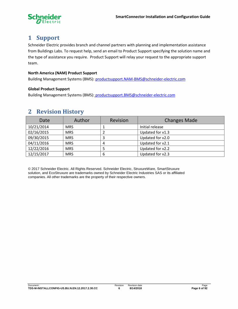
1 Support Schneider Electric provides branch and channel partners with planning and implementation assistance
from Buildings Labs. To request help, send an email to Product Support specifying the solution name and
the type of assistance you require. Product Support will relay your request to the appropriate support
team.
North America (NAM) Product Support
Building Management Systems (BMS): [email protected]
Global Product Support
Building Management Systems (BMS): [email protected]
2 Revision History
Date Author Revision Changes Made 10/21/2014 MRS 1 Initial release
02/16/2015 MRS 2 Updated for v1.3
09/30/2015 MRS 3 Updated for v2.0
04/11/2016 MRS 4 Updated for v2.1
12/22/2016 MRS 5 Updated for v2.2
12/15/2017 MRS 6 Updated for v2.3
© 2017 Schneider Electric. All Rights Reserved. Schneider Electric, StruxureWare, SmartStruxure solution, and EcoStruxure are trademarks owned by Schneider Electric Industries SAS or its affiliated companies. All other trademarks are the property of their respective owners.

SmartConnector Installation and Configuration Guide
Document : Revision Revision date Page
TDS-M-INSTALLCONFIG-US.BU.N.EN.12.2017.2.30.CC 6 8/14/2018 Page 7 of 92
3 Overview
3.1 Scope
This document is intended as a guide to aid in the installation, configuration, monitoring, and control of
SmartConnector – the windows service middleware framework developed by Schneider Electric
Buildings Labs. This document assumes the reader has the requisite knowledge for installing and
configuring Windows software in general and Windows services in particular. Familiarity with .NET
assemblies and their deployment and configuration will be beneficial.
This document will not cover the details in consuming SmartConnector’s libraries for the purpose of
authoring customized middleware applications (SmartConnector Extensions) to run in the
SmartConnector Service. That information can be found in SmartConnector Developers Guide.
3.2 What is SmartConnector?
When developing solutions, there is frequently a need for software that can bridge the gap between
Schneider Electric systems and third-party systems and data sources. This software goes by varying
names: protocol shims, glue logic, or more generally, middleware. As different projects are analyzed,
patterns begin to emerge where this middleware performs similar actions with only minor variations
from solution to solution. SmartConnector was conceived to be this middleware framework.
SmartConnector is an extensible and configurable application framework. At its simplest,
SmartConnector is a multi-threaded Windows service. Threads are configured to execute custom code
written by solution providers and integrators.
SmartConnector also provides the infrastructure to provision HTTP endpoints. These endpoints can
either serve data to Schneider Electric systems and third-party clients via Schneider Electric’s
EcoStruxure Web Services (EWS) SOAP protocol or generic RESTful services.
3.2.1 Processor
A Processor is custom code that is designed to accomplish a task. While SmartConnector does include
some sample Processors for operational validation and demonstration purposes, Processors are written
by others using SmartConnector’s public libraries (see SmartConnector Developers Guide). These
libraries are packaged into a SmartConnector Extension.
The scope of a Processor can vary from simple to very complicated. Often, several Processors are
required to function cooperatively to accomplish the necessary tasks for a solution.
3.2.2 Processor Configuration
While a Processor defines how work is accomplished, a Processor Configuration specifically dictates
what gets accomplished. A Processor Configuration contains all of the information needed to instantiate
a class at runtime, hydrate all properties of that class, and validate that everything is correct before
finally executing the Processor. A Processor Configuration also links to the requisite scheduling
information which determines when and how often SmartConnector will run a Processor.
SmartConnector Installation and Configuration Guide
Document : Revision Revision date Page
TDS-M-INSTALLCONFIG-US.BU.N.EN.12.2017.2.30.CC 6 8/14/2018 Page 8 of 92
3.2.3 SmartConnector EWS Servers
SmartConnector provides the infrastructure to serve data to any EWS Client via native SmartConnector
EWS Servers. Multiple EWS Servers can be provisioned, each with its own data isolated from the others.
This data can be static data stored in SmartConnector’s database or data dynamically obtained from a
third party via a custom EWS Server. As with Processors, custom EWS Servers are written by third
parties and packaged into a SmartConnector Extension.
3.2.4 REST Endpoints
While EWS is useful for passing data to and from those Schneider Electric systems which support it, third
parties interested in that same data do not know how to “speak EWS”. To remedy this, SmartConnector
includes a configurable RestProvider infrastructure. An EwsRestProvider class is configured with an
Endpoint Configuration to serve data from either a native SmartConnector EWS Server or one based on
the EWS SOAP protocol. Custom RestProviders can also be written by third parties and packed into a
SmartConnector Extension.
3.2.5 Endpoint Configuration
In the same way a Processor Configuration defines how a Processor runs; an Endpoint Configuration
defines how a REST Endpoint will be provisioned. An Endpoint Configuration contains all of the
information needed to instantiate a class at runtime, hydrate all properties of that class, and validate
that everything is correct before finally provisioning the REST Endpoint.
3.2.6 SmartConnector Portal
SmartConnector includes an integrated web portal user interface which is installed along with the
service. This portal is the primary method to configure Processors, Endpoints, and EWS Servers as well
as monitor and control all aspects of SmartConnector.
3.2.7 Worker Manager and Workers
Workers represent the threads in SmartConnector that execute Processors. The number of available
Workers is configurable but is generally limited by the host system hardware. When not actively
running a Processor, Workers are inactive, waiting for a command from the Worker Manager. In this
state, Workers consume virtually no system resources.
The Worker Manager is responsible for selecting a Processor Configuration, instantiating its defined
Processor and passing it off to an idle Worker for execution. The Worker Manager also listens to input
to start or stop a Processor or EWS Server as required.
3.2.8 Extension
The term “Extension” is used to define any class assembly which contains code which can run in
SmartConnector. Extensions can contain Processors, EWS Server Hosts, RestProviders, and any
combination of these. Extensions are written by SmartConnector Developers to solve an application
problem.

SmartConnector Installation and Configuration Guide
Document : Revision Revision date Page
TDS-M-INSTALLCONFIG-US.BU.N.EN.12.2017.2.30.CC 6 8/14/2018 Page 9 of 92
3.2.9 Persistent Data Store
SmartConnector is backed by a SQL database to persist all manner of data including setup parameters,
configuration data, schedule data, and EWS server data. SmartConnector also provides a Processor
Values data store that Processors can access directly. This data store can be used to save state between
run iterations of the Processor or to enable collaboration between multiple Processors.
3.2.10 In-Memory Cache
In addition to a persistent data store, SmartConnector provides a mechanism to have a volatile in-
memory cache of data. A singleton class available to any Processor, REST Provider, or EWS Server
provides strongly typed access to any data the author wishes to store.
3.2.11 Logging
SmartConnector provides an integrated logging framework. Logging levels of Info, Status, Error, Debug,
and Trace are extensively used throughout the SmartConnector runtime and public libraries. The Logger
is also available to Extension authors for adding their own log information to the common log file
output.
3.2.12 Licensing
SmartConnector’s framework is licensed. Commercial licenses can be obtained at
www.smartconnectorserver.com. Additionally, Extension developers can choose to license their code
too. Consult with your Extension Developer for a license if this is required.
SmartConnector Installation and Configuration Guide
Document : Revision Revision date Page
TDS-M-INSTALLCONFIG-US.BU.N.EN.12.2017.2.30.CC 6 8/14/2018 Page 10 of 92
4 Installation
4.1 Prerequisites
SmartConnector is a Windows Service and can run on any of the supported operating systems listed in
the appendix. The following are required prior to running the SmartConnector installer.
4.1.1.1 Database Server
Prior to installing SmartConnector, you must have installed, or have access to, a Microsoft SQL database.
Refer to the appendix for a list of supported database server versions. This database server does not
need to be collocated on the same physical machine where you will be installing SmartConnector but
the two servers must have network connectivity.
4.1.1.2 Windows Updates
It is assumed that all available Windows updates have been installed on the target machine.
4.1.1.3 .NET Framework
SmartConnector requires the .NET version 4.5 framework. This must be installed.
4.2 Installing SmartConnector Windows Service
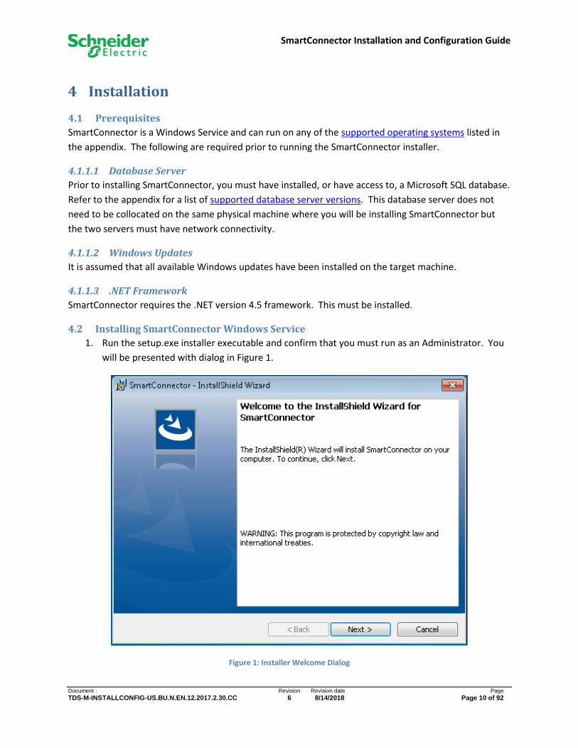
1. Run the setup.exe installer executable and confirm that you must run as an Administrator. You
will be presented with dialog in Figure 1.
Figure 1: Installer Welcome Dialog
SmartConnector Installation and Configuration Guide
Document : Revision Revision date Page
TDS-M-INSTALLCONFIG-US.BU.N.EN.12.2017.2.30.CC 6 8/14/2018 Page 11 of 92
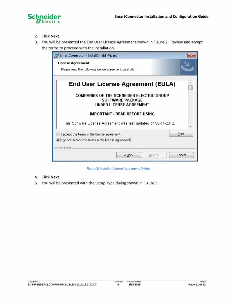
2. Click Next.
3. You will be presented the End User License Agreement shown in Figure 2. Review and accept
the terms to proceed with the installation.
Figure 2: Installer License Agreement Dialog
4. Click Next.
5. You will be presented with the Setup Type dialog shown in Figure 3.

SmartConnector Installation and Configuration Guide
Document : Revision Revision date Page
TDS-M-INSTALLCONFIG-US.BU.N.EN.12.2017.2.30.CC 6 8/14/2018 Page 12 of 92
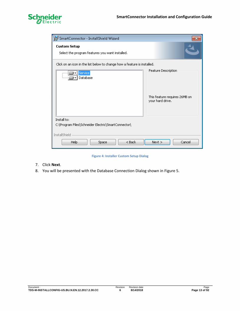
Figure 3: Installer Install Options Dialog
6. Choose the Setup Type you wish to perform. If this is a new installation, you must choose
Complete. If you are reinstalling and wish to skip the database installation, you can chose
Custom and deselect the Database component (see Figure 4). If you choose this setup type you
will be responsible for resolving the connection configuration manually and any database
upgrades that are needed.
SmartConnector Installation and Configuration Guide
Document : Revision Revision date Page
TDS-M-INSTALLCONFIG-US.BU.N.EN.12.2017.2.30.CC 6 8/14/2018 Page 13 of 92
Figure 4: Installer Custom Setup Dialog
7. Click Next.
8. You will be presented with the Database Connection Dialog shown in Figure 5.
SmartConnector Installation and Configuration Guide
Document : Revision Revision date Page
TDS-M-INSTALLCONFIG-US.BU.N.EN.12.2017.2.30.CC 6 8/14/2018 Page 14 of 92
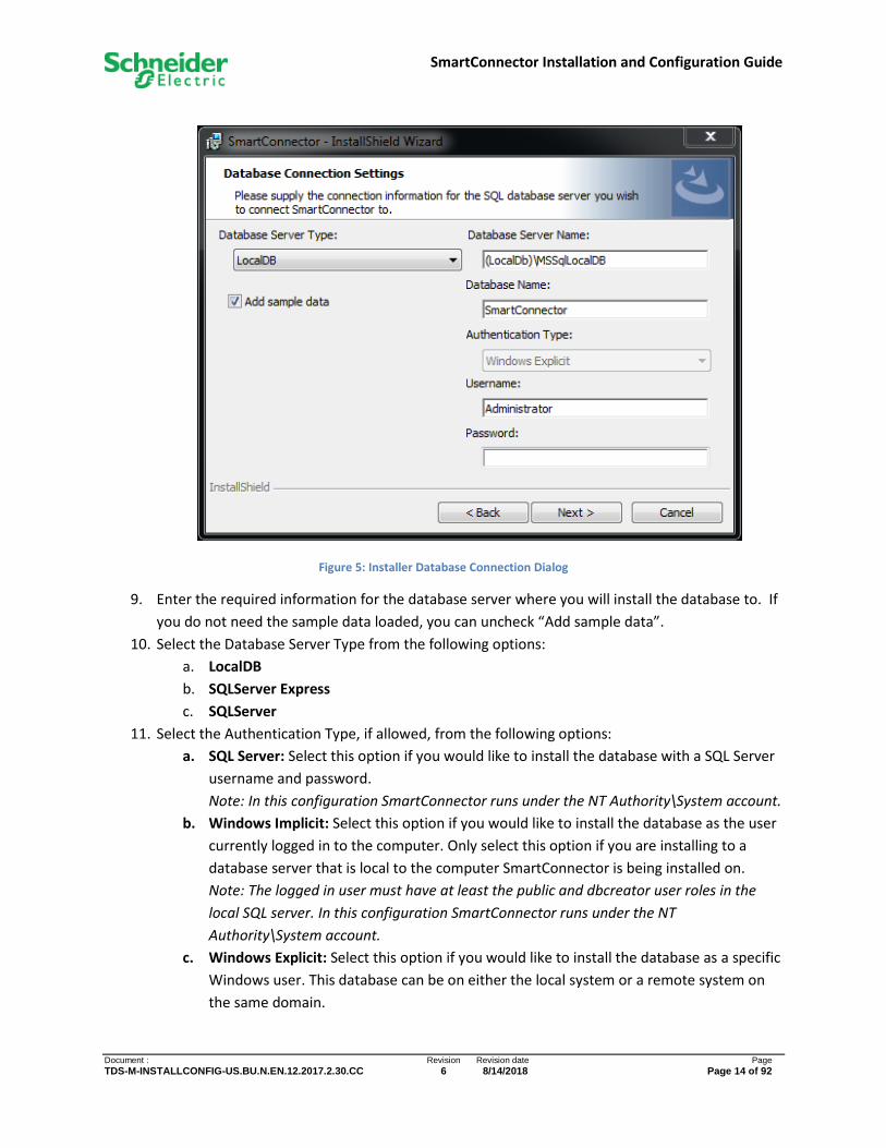
Figure 5: Installer Database Connection Dialog
9. Enter the required information for the database server where you will install the database to. If
you do not need the sample data loaded, you can uncheck “Add sample data”.
10. Select the Database Server Type from the following options:
a. LocalDB
b. SQLServer Express
c. SQLServer
11. Select the Authentication Type, if allowed, from the following options:
a. SQL Server: Select this option if you would like to install the database with a SQL Server
username and password.
Note: In this configuration SmartConnector runs under the NT Authority\System account.
b. Windows Implicit: Select this option if you would like to install the database as the user
currently logged in to the computer. Only select this option if you are installing to a
database server that is local to the computer SmartConnector is being installed on.
Note: The logged in user must have at least the public and dbcreator user roles in the
local SQL server. In this configuration SmartConnector runs under the NT
Authority\System account.
c. Windows Explicit: Select this option if you would like to install the database as a specific
Windows user. This database can be on either the local system or a remote system on
the same domain.
SmartConnector Installation and Configuration Guide
Document : Revision Revision date Page
TDS-M-INSTALLCONFIG-US.BU.N.EN.12.2017.2.30.CC 6 8/14/2018 Page 15 of 92
Note: The specified user must have at least the public and dbcreator user roles in the SQL
server. In this configuration SmartConnector runs under the user account entered.
12. Enter the Username and Password as required. When using “Windows Explicit” authentication,
you must include the domain name as part of the user name (e.g. domain/username).
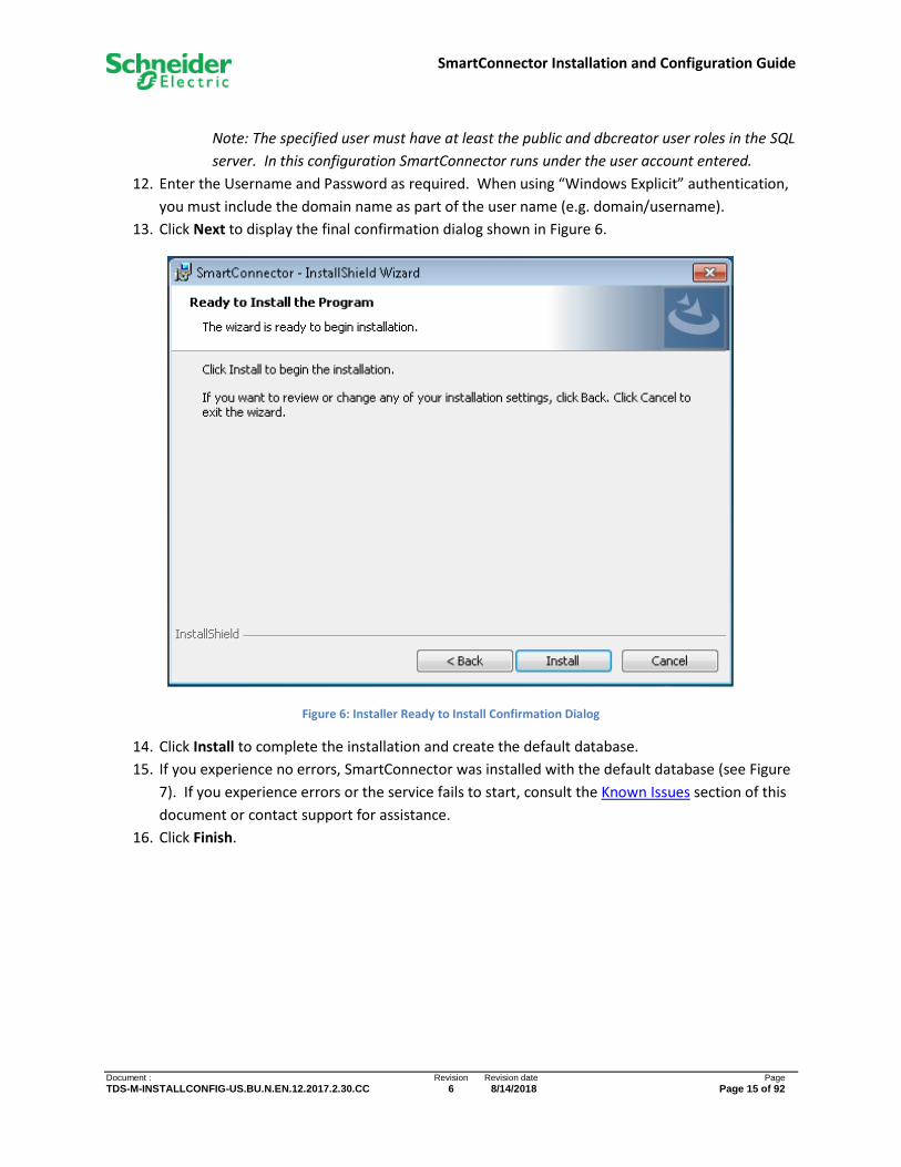
13. Click Next to display the final confirmation dialog shown in Figure 6.
Figure 6: Installer Ready to Install Confirmation Dialog
14. Click Install to complete the installation and create the default database.
15. If you experience no errors, SmartConnector was installed with the default database (see Figure
7). If you experience errors or the service fails to start, consult the Known Issues section of this
document or contact support for assistance.
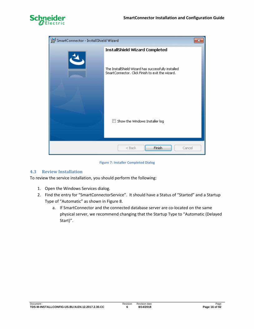
16. Click Finish.
SmartConnector Installation and Configuration Guide
Document : Revision Revision date Page
TDS-M-INSTALLCONFIG-US.BU.N.EN.12.2017.2.30.CC 6 8/14/2018 Page 16 of 92
Figure 7: Installer Completed Dialog
4.3 Review Installation
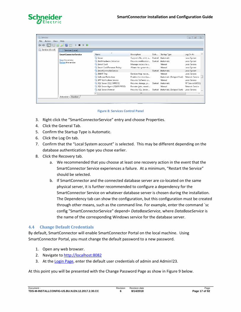
To review the service installation, you should perform the following:
1. Open the Windows Services dialog.
2. Find the entry for “SmartConnectorService”. It should have a Status of “Started” and a Startup
Type of “Automatic” as shown in Figure 8.
a. If SmartConnector and the connected database server are co-located on the same
physical server, we recommend changing that the Startup Type to “Automatic (Delayed
Start)”.
SmartConnector Installation and Configuration Guide
Document : Revision Revision date Page
TDS-M-INSTALLCONFIG-US.BU.N.EN.12.2017.2.30.CC 6 8/14/2018 Page 17 of 92
Figure 8: Services Control Panel
3. Right click the “SmartConnectorService” entry and choose Properties.
4. Click the General Tab.
5. Confirm the Startup Type is Automatic.
6. Click the Log On tab.
7. Confirm that the “Local System account” is selected. This may be different depending on the
database authentication type you chose earlier.
8. Click the Recovery tab.
a. We recommended that you choose at least one recovery action in the event that the
SmartConnector Service experiences a failure. At a minimum, “Restart the Service”
should be selected.
b. If SmartConnector and the connected database server are co-located on the same
physical server, it is further recommended to configure a dependency for the
SmartConnector Service on whatever database server is chosen during the installation.
The Dependency tab can show the configuration, but this configuration must be created
through other means, such as the command line. For example, enter the command `sc
config "SmartConnectorService" depend= DataBaseService, where DataBaseService is
the name of the corresponding Windows service for the database server.
4.4 Change Default Credentials
By default, SmartConnector will enable SmartConnector Portal on the local machine. Using
SmartConnector Portal, you must change the default password to a new password.
1. Open any web browser.
2. Navigate to http://localhost:8082
3. At the Login Page, enter the default user credentials of admin and Admin!23.
At this point you will be presented with the Change Password Page as show in Figure 9 below.
SmartConnector Installation and Configuration Guide
Document : Revision Revision date Page
TDS-M-INSTALLCONFIG-US.BU.N.EN.12.2017.2.30.CC 6 8/14/2018 Page 18 of 92
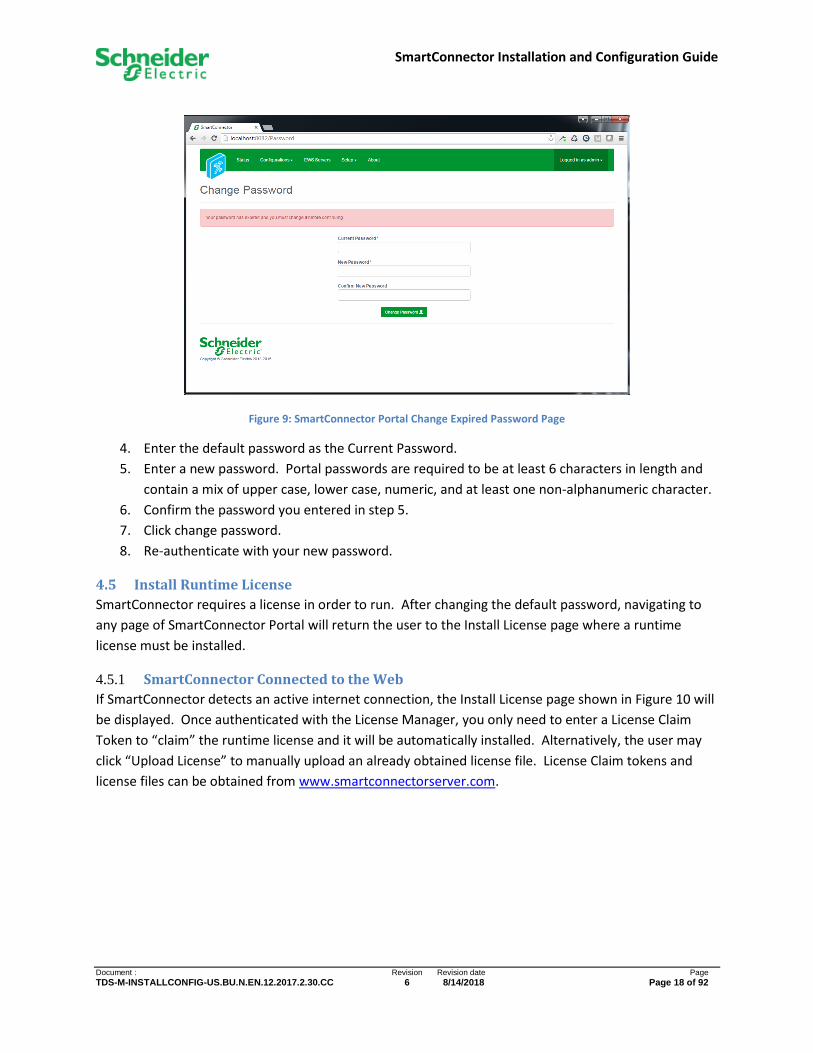
Figure 9: SmartConnector Portal Change Expired Password Page
4. Enter the default password as the Current Password.
5. Enter a new password. Portal passwords are required to be at least 6 characters in length and
contain a mix of upper case, lower case, numeric, and at least one non-alphanumeric character.
6. Confirm the password you entered in step 5.
7. Click change password.
8. Re-authenticate with your new password.
4.5 Install Runtime License
SmartConnector requires a license in order to run. After changing the default password, navigating to
any page of SmartConnector Portal will return the user to the Install License page where a runtime
license must be installed.
4.5.1 SmartConnector Connected to the Web
If SmartConnector detects an active internet connection, the Install License page shown in Figure 10 will
be displayed. Once authenticated with the License Manager, you only need to enter a License Claim
Token to “claim” the runtime license and it will be automatically installed. Alternatively, the user may
click “Upload License” to manually upload an already obtained license file. License Claim tokens and
license files can be obtained from www.smartconnectorserver.com.

SmartConnector Installation and Configuration Guide
Document : Revision Revision date Page
TDS-M-INSTALLCONFIG-US.BU.N.EN.12.2017.2.30.CC 6 8/14/2018 Page 19 of 92
Figure 10: Portal Install License (Connected)
4.5.2 SmartConnector Not Connected to the Web
If SmartConnector fails to detect an active internet connection, the Install License page shown in Figure
11 will be displayed.
Directions are provided on how to download a license file from www.smartconnectorserver.com.

SmartConnector Installation and Configuration Guide
Document : Revision Revision date Page
TDS-M-INSTALLCONFIG-US.BU.N.EN.12.2017.2.30.CC 6 8/14/2018 Page 20 of 92
Figure 11: Portal Install License (Not Connected)
4.6 Confirm Settings
SmartConnector installs the service with some default settings. After changing the password, you
should confirm the system settings meet the criteria for how SmartConnector will be used.
1. Open any web browser.
2. Navigate to http://localhost:8082
3. Authenticate with the credentials you used in the prior section.
4. Click Setup-Service Settings.
5. You should see a page similar to Figure 12.

SmartConnector Installation and Configuration Guide
Document : Revision Revision date Page
TDS-M-INSTALLCONFIG-US.BU.N.EN.12.2017.2.30.CC 6 8/14/2018 Page 21 of 92
Figure 12: SmartConnector Portal Service Settings Page
6. To edit any field, you can either click the edit icon ( ) in that field or click the Edit All button
to enable all fields for editing.
7. Review and/or change values as desired. Unless otherwise noted, changes made here will take
affect without a service restart.
Instance Name – Appears in the browser tab and can be useful to distinguish which
SmartConnector instance you are looking at if you are connecting to multiple deployed
instances from a single browser.
Logging Level – Maximum level SmartConnector will log. Possible values are None, Error, Status,
Info, Debug, Trace, All. This setting is used in conjunction with Logging Filters to control how
much information is captured in the log files.
Password Age Limit – The maximum number of days before a Portal user’s password will expire.
Portal Address – Address of SmartConnector Portal. For security concerns, the default value will
be 127.0.0.1 which means the portal can only be accessed from the local machine. If broader
access is required, this value can be modified by using the “+ syntax” e.g. http://+:8082. This
will allow access to any IP or DNS which resolves to the local machine. If you plan to secure the
endpoint with a certificate, then the protocol shown here should be changed to https to match.

SmartConnector Installation and Configuration Guide
Document : Revision Revision date Page
TDS-M-INSTALLCONFIG-US.BU.N.EN.12.2017.2.30.CC 6 8/14/2018 Page 22 of 92
Entering an empty value will disable the portal. Use caution! Consult the Security
Considerations for suggestions on how best to configure this.
Processor Runtime Limit – The maximum amount of time a Processor Configuration is given to
complete before it is deemed to be unresponsive and is terminated. Unless otherwise
instructed this value should not need to be modified.
Worker Manager Sleep – The amount of time that the Worker Manager will idle before
determining if there are Processors that need to be invoked. Unless otherwise instructed this
value should not need to be modified.
Worker Thread Count – The number of concurrent Processors that can be executed. This
number may be increased but is largely dependent on the host machine’s number of logical
processors. To determine the number of logical processors, open a command prompt and enter
the command: WMIC CPU Get DeviceID,NumberOfCores,NumberOfLogicalProcessors. While you can
set this value greater than the number of logical processors, it represents the number of
concurrent workers that can run without potential operating system queuing. You will need to
restart the SmartConnector Service for this change to take effect.
8. After you have made the necessary changes, click Save to save them to the database.
SmartConnector Installation and Configuration Guide
Document : Revision Revision date Page
TDS-M-INSTALLCONFIG-US.BU.N.EN.12.2017.2.30.CC 6 8/14/2018 Page 23 of 92
5 SmartConnector Portal Monitoring and configuring SmartConnector is done via the integrated SmartConnector Portal. The use
of SmartConnector Portal is described in detail in the following sections.
5.1 Overview
SmartConnector Portal is a web based application which can be viewed in any web browser. Its
responsive design will automatically adapt to different device sizes and orientations.
5.1.1 Supported Browsers
SmartConnector Portal has no restrictions or affinity to any browser vendor. You are free to use any
common browser. Additionally, mobile device browsers are supported providing the device has
network connectivity to the configured endpoint of SmartConnector Portal. The only requirement is
that JavaScript is enabled in your browser. The following browsers have been tested:
• Chrome
• Firefox
• Internet Explorer
• Safari
• Safari for iPhone
5.1.2 Navigation
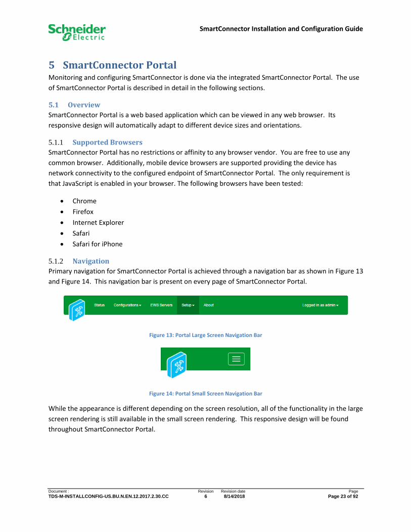
Primary navigation for SmartConnector Portal is achieved through a navigation bar as shown in Figure 13
and Figure 14. This navigation bar is present on every page of SmartConnector Portal.
Figure 13: Portal Large Screen Navigation Bar
Figure 14: Portal Small Screen Navigation Bar
While the appearance is different depending on the screen resolution, all of the functionality in the large
screen rendering is still available in the small screen rendering. This responsive design will be found
throughout SmartConnector Portal.
SmartConnector Installation and Configuration Guide
Document : Revision Revision date Page
TDS-M-INSTALLCONFIG-US.BU.N.EN.12.2017.2.30.CC 6 8/14/2018 Page 24 of 92
5.1.2.1 Status
This option will display the Status Page. From this page the user can view the status of Threads, Active
Endpoints, Configuration Requests, and EWS Server Requests.
5.1.2.2 Configurations
This option will display a sub-menu that will allow access to the Processor Configuration Listing Page or
Endpoint Configuration Listing Page.
5.1.2.3 EWS Servers
This option will display the EWS Server Listing Page. All EWS Servers can be viewed from this page.
Additionally, the user can choose to edit, start, stop, or delete an EWS Server. The user can also initiate
creating a new EWS Server from this page.
5.1.2.4 Setup
This option will display a sub-menu that will allow access to the License Listing Page, Configuration
Schedule Listing Page, Processor Values Page, Logging Filters Page, Users Page, and Service Settings
Page.
5.1.2.5 About
This option will display the About Page. From this page the user can view information about the
installed version of the SmartConnector and the state of the SmartConnector Service.
5.1.2.6 Logged in as …
This option will display a sub-menu that will allow the current user to log out or access the Change
Password Page. The name of the current user is shown in this menu item.
5.1.3 Service Offline
SmartConnector uses no webservers. All content is served directly from the SmartConnector Windows
service. As a result, a user viewing a SmartConnector Portal page may be unaware if the service goes
offline. If this occurs, subsequent requests for content will fail and the user may have an inconsistent
experience depending on the browser used.
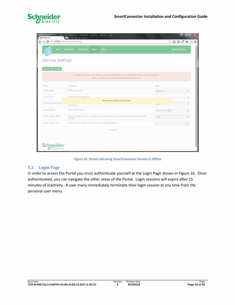
To address this, SmartConnector web pages monitor the health of the service at all times. If the service
goes offline for any reason, the page in the browser will show this state automatically. This will ensure
that the user is made aware of a possible problem in the service. Figure 15 shows an example of what
this will look like. When the service returns to normal operation, the warning will subsequently
disappear.
SmartConnector Installation and Configuration Guide
Document : Revision Revision date Page
TDS-M-INSTALLCONFIG-US.BU.N.EN.12.2017.2.30.CC 6 8/14/2018 Page 25 of 92
Figure 15: Portal Indicating SmartConnector Service is Offline
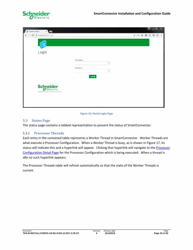
5.2 Login Page
In order to access the Portal you must authenticate yourself at the Login Page shown in Figure 16. Once
authenticated, you can navigate the other areas of the Portal. Login sessions will expire after 15
minutes of inactivity. A user many immediately terminate their login session at any time from the
personal user menu.
SmartConnector Installation and Configuration Guide
Document : Revision Revision date Page
TDS-M-INSTALLCONFIG-US.BU.N.EN.12.2017.2.30.CC 6 8/14/2018 Page 26 of 92
Figure 16: Portal Login Page
5.3 Status Page
The status page contains a tabbed representation to present the status of SmartConnector.
5.3.1 Processor Threads
Each entry in the contained table represents a Worker Thread in SmartConnector. Worker Threads are
what execute a Processor Configuration. When a Worker Thread is busy, as is shown in Figure 17, its
status will indicate this and a hyperlink will appear. Clicking that hyperlink will navigate to the Processor
Configuration Detail Page for the Processor Configuration which is being executed. When a thread is
idle no such hyperlink appears.
The Processor Threads table will refresh automatically so that the state of the Worker Threads is
current.

SmartConnector Installation and Configuration Guide
Document : Revision Revision date Page
TDS-M-INSTALLCONFIG-US.BU.N.EN.12.2017.2.30.CC 6 8/14/2018 Page 27 of 92
Figure 17: Portal Status Page – Processor Threads
5.3.2 Active Endpoints
Each entry in the contained table represents an HTTP endpoint which has been provisioned by
SmartConnector. When an endpoint is active as is shown in Figure 18, hyperlinks will be available to
quickly access the Endpoint Configuration Detail Page for the Endpoint Configuration which is
provisioned and the optional Swagger documentation page. See SmartConnector EWS REST API
Gateway for more information.
Figure 18: Portal Status Page – Active Endpoints
5.3.3 Managed Clients
Each entry in the contained table represents a managed client connection which is being managed by
SmartConnector. When a client is available as is shown in Figure 19, status information will be displayed
for that connection.

SmartConnector Installation and Configuration Guide
Document : Revision Revision date Page
TDS-M-INSTALLCONFIG-US.BU.N.EN.12.2017.2.30.CC 6 8/14/2018 Page 28 of 92
Figure 19: Portal Status Page - Managed Clients
Requests can be filtered as needed by selecting an appropriate value for any filterable parameter.
5.3.4 Configuration Requests
A Configuration Request is a request made to start or stop either a Processor Configuration or Endpoint
Configuration from other areas of the portal. The status of each request is maintained by
SmartConnector and updated when appropriate.
In the example shown in Figure 20 a single request to start “Long Running Processor” was “Completed
As Requested”. Clicking the Configuration column hyperlink will navigate to the Processor Configuration
Detail Page for the corresponding Processor Configuration.
Requests can be filtered as needed by selecting an appropriate value for any filterable parameter.
Figure 20: Portal Status Page - Configuration Requests
Over time, this table will include many pages of data with more recent data appearing at the top of the
list. At any time, the user can elect to purge this data by clicking the Purge All button. When clicked, all
non-pending requests, in the current filtered set, will be deleted from the database.
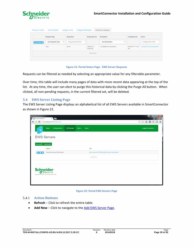
5.3.5 EWS Server Requests
An EWS Server Request is a request made to start or stop an EWS Server from other areas of the portal.
The status of each request is maintained by SmartConnector and updated when appropriate. In the
example shown in Figure 21 a single request to start “SmartConnector EWS Server” was “Completed As
Requested”. Clicking the available hyperlink will navigate to the EWS Server Detail Page for the
corresponding EWS Server.
SmartConnector Installation and Configuration Guide
Document : Revision Revision date Page
TDS-M-INSTALLCONFIG-US.BU.N.EN.12.2017.2.30.CC 6 8/14/2018 Page 29 of 92
Figure 21: Portal Status Page - EWS Server Requests
Requests can be filtered as needed by selecting an appropriate value for any filterable parameter.
Over time, this table will include many pages of data with more recent data appearing at the top of the
list. At any time, the user can elect to purge this historical data by clicking the Purge All button. When
clicked, all non-pending requests, in the current filtered set, will be deleted.
5.4 EWS Server Listing Page
The EWS Server Listing Page displays an alphabetical list of all EWS Servers available in SmartConnector
as shown in Figure 22.
Figure 22: Portal EWS Servers Page
5.4.1 Action Buttons
• Refresh – Click to refresh the entire table.
• Add New – Click to navigate to the Add EWS Server Page.

SmartConnector Installation and Configuration Guide
Document : Revision Revision date Page
TDS-M-INSTALLCONFIG-US.BU.N.EN.12.2017.2.30.CC 6 8/14/2018 Page 30 of 92
5.4.2 Data Table
Each entry in the table contains an action toolbar, Name, and URL of the Server. The action toolbar
always has three buttons. From left to right these are:
• Edit – Click to navigate to the EWS Server Detail Page.
• Delete – Click to delete the EWS Server from the database. If the EWS Server is running it will
first be stopped.
• Toggle Button – The final button is used to both convey status and action. If the action bar
contains a “Play Button” the EWS Server is NOT RUNNING. Click to add an EWS
Server Request to start the EWS Server. If the action bar contains a “Stop Button”
the EWS Server is RUNNING. Click to add an EWS Server Request to stop the EWS Server.
5.5 Add EWS Server Page
The Add EWS Server Page provides a wizard interface for creating an EWS Server from a SmartConnector
Extension class assembly.
SmartConnector includes a default EWS Server Extension assembly which can be used to demonstrate
adding an EWS Server to your installation.
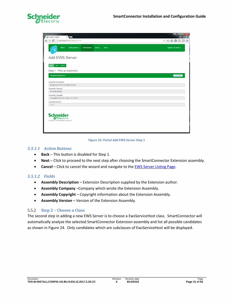
5.5.1 Step 1 – Pick an assembly
The first step in adding a new EWS Server is to choose the SmartConnector Extension assembly which
contains the EwsServiceHost you want to configure. SmartConnector will automatically analyze the
SmartConnector install directory and display all possible assemblies and the number of available service
host candidates which could be configured as shown in Figure 23.
As you select items in the list, the detailed assembly information will be noted at the bottom of the
page. If the desired assembly does not appear in the list of options, check the SmartConnector log file
for any errors, such as missing dependent assemblies. See the troubleshooting section of this document
for more details.
SmartConnector Installation and Configuration Guide
Document : Revision Revision date Page
TDS-M-INSTALLCONFIG-US.BU.N.EN.12.2017.2.30.CC 6 8/14/2018 Page 31 of 92
Figure 23: Portal Add EWS Server Step 1
5.5.1.1 Action Buttons
• Back – This button is disabled for Step 1.
• Next – Click to proceed to the next step after choosing the SmartConnector Extension assembly.
• Cancel – Click to cancel the wizard and navigate to the EWS Server Listing Page.
5.5.1.2 Fields
• Assembly Description – Extension Description supplied by the Extension author.
• Assembly Company –Company which wrote the Extension Assembly.
• Assembly Copyright – Copyright information about the Extension Assembly.
• Assembly Version – Version of the Extension Assembly.
5.5.2 Step 2 – Choose a Class
The second step in adding a new EWS Server is to choose a EwsServiceHost class. SmartConnector will
automatically analyze the selected SmartConnector Extension assembly and list all possible candidates
as shown in Figure 24. Only candidates which are subclasses of EwsServiceHost will be displayed.

SmartConnector Installation and Configuration Guide
Document : Revision Revision date Page
TDS-M-INSTALLCONFIG-US.BU.N.EN.12.2017.2.30.CC 6 8/14/2018 Page 32 of 92
Figure 24: Portal Add EWS Server Step 2
5.5.2.1 Action Buttons
• Back – Click to return to Step 1.
• Next – Click to continue configuration after selecting a service host class.
• Cancel – Click to quit the wizard and navigate to the EWS Server Listing Page.
5.5.3 Step 3 – Name EWS Server
The third step in adding a new EWS Server is to provide the remaining details required to bootstrap the
server endpoint as shown in Figure 25. SmartConnector will display the selections made in Step 1 and
Step 2 but these are no longer editable at this point.

SmartConnector Installation and Configuration Guide
Document : Revision Revision date Page
TDS-M-INSTALLCONFIG-US.BU.N.EN.12.2017.2.30.CC 6 8/14/2018 Page 33 of 92
Figure 25: Portal Add EWS Server Step 3
5.5.3.1 Fields
• Name - EWS Server names must be unique within SmartConnector.
• Address – The full URL you wish to accept traffic on e.g. http://localhost:57630/DataExchange.
• Realm - Optional realm value for HTTP Digest authentication.
• Auto Start – Indicates whether the server will automatically start when SmartConnector starts.
• User Name – UserName for EWS HTTP Digest authentication.
• Password – Password for EWS HTTP Digest authentication.
5.5.3.2 Action Buttons
• Back – Click to return to Step 2.
• Finish – Click to save the new EWS Server and navigate to the EWS Server Detail Page for the
new EWS Server.
• Cancel – Click to quit the wizard and navigate to the EWS Server Listing Page.
5.6 EWS Server Detail Page
The EWS Server Detail Page allows the user to view and edit a SmartConnector EWS Server’s settings
and contents. Figure 26 shows what the EWS Server Page might look after adding a typical
SmartConnector EWS Server (see Add EWS Server Page).

SmartConnector Installation and Configuration Guide
Document : Revision Revision date Page
TDS-M-INSTALLCONFIG-US.BU.N.EN.12.2017.2.30.CC 6 8/14/2018 Page 34 of 92
Figure 26: Portal EWS Server Detail Page
5.6.1 Action Buttons
• Start – Available when the EWS Server is NOT RUNNING. Click to add an EWS Server Request to
start the EWS Server.
• Stop – Available when the EWS Server is RUNNING. Click to add an EWS Server Request to stop
the EWS Server.
5.6.2 Page Layout
The page layout is divided into two tabs (see Figure 26).
5.6.2.1 Contents Tab
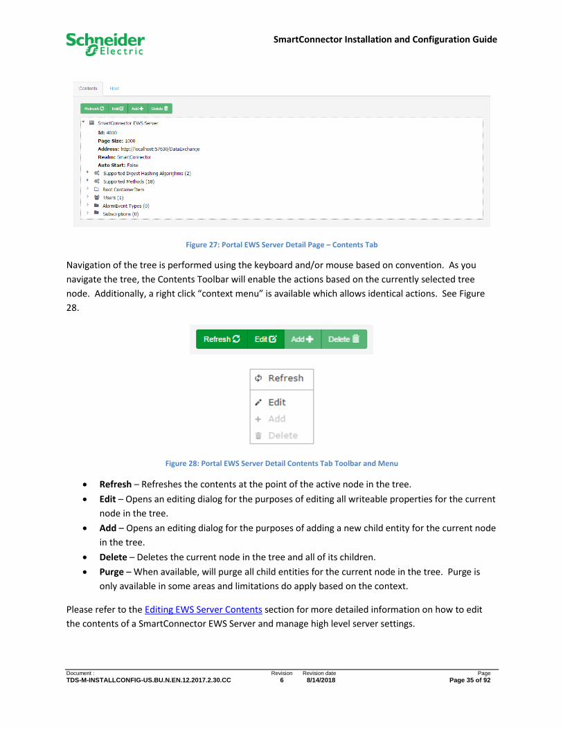
The contents of an EWS Server is displayed in tree format as shown in Figure 27.
SmartConnector Installation and Configuration Guide
Document : Revision Revision date Page
TDS-M-INSTALLCONFIG-US.BU.N.EN.12.2017.2.30.CC 6 8/14/2018 Page 35 of 92
Figure 27: Portal EWS Server Detail Page – Contents Tab
Navigation of the tree is performed using the keyboard and/or mouse based on convention. As you
navigate the tree, the Contents Toolbar will enable the actions based on the currently selected tree
node. Additionally, a right click “context menu” is available which allows identical actions. See Figure
28.
Figure 28: Portal EWS Server Detail Contents Tab Toolbar and Menu
• Refresh – Refreshes the contents at the point of the active node in the tree.
• Edit – Opens an editing dialog for the purposes of editing all writeable properties for the current
node in the tree.
• Add – Opens an editing dialog for the purposes of adding a new child entity for the current node
in the tree.
• Delete – Deletes the current node in the tree and all of its children.
• Purge – When available, will purge all child entities for the current node in the tree. Purge is
only available in some areas and limitations do apply based on the context.
Please refer to the Editing EWS Server Contents section for more detailed information on how to edit
the contents of a SmartConnector EWS Server and manage high level server settings.

SmartConnector Installation and Configuration Guide
Document : Revision Revision date Page
TDS-M-INSTALLCONFIG-US.BU.N.EN.12.2017.2.30.CC 6 8/14/2018 Page 36 of 92
5.6.2.2 Host Tab
The Host Tab contains the information for the SmartConnector Extension which represents the “host”
controller logic for the EWS Server implementation as show in Figure 29.
Figure 29: Portal EWS Server Detail Host Tab
• Class Name – The name of the EwsServiceHost subclass configured. This field is read only.
• Assembly File – The complete file path where the Extension Assembly is located. This field is
read only.
• Assembly Description – Extension Description supplied by the Extension author. This field is
read only.
• Assembly Company –Company which wrote the Extension Assembly. This field is read only.
• Assembly Copyright – Copyright information about the Extension Assembly. This field is read
only.
• Assembly Version – Version of the Extension Assembly. This field is read only.
5.7 Processor Configurations Listing Page
The Processor Configuration Listing Page displays an alphabetical list of all Processor Configurations
available in the SmartConnector as shown in Figure 30.

SmartConnector Installation and Configuration Guide
Document : Revision Revision date Page
TDS-M-INSTALLCONFIG-US.BU.N.EN.12.2017.2.30.CC 6 8/14/2018 Page 37 of 92
Figure 30: Portal Processor Configuration Listing Page
5.7.1 Action Buttons
The following buttons are always available.
• Refresh – Click to refresh of the entire table.
• Add New – Click to navigate to the Add Processor Configuration Page.
5.7.2 Data Table
Each entry in the table contains an action toolbar, Name, and Description of the Processor
Configuration. Additionally, metrics are displayed which show how often the configuration has been run
(Execution Count), the time needed to complete the last execution (Last Execution Time), and the
cumulative time for all executions (Total Execution Time). The current page of results will refresh
automatically so that the state of all Processor Configuration remains current.
The action toolbar in each row always has four buttons. From left to right these are:
• Edit – Click to navigate to the Processor Configuration Detail Page.
• Clone – Click to create a complete copy of the Processor Configuration and navigate to the
Processor Configuration Detail Page for the newly cloned item. NOTE: Cloned Processor
Configurations are always marked as Is Active = False. This will allow the user to complete any
modifications to the Processor Configuration prior to it starting on a predefined Schedule.

SmartConnector Installation and Configuration Guide
Document : Revision Revision date Page
TDS-M-INSTALLCONFIG-US.BU.N.EN.12.2017.2.30.CC 6 8/14/2018 Page 38 of 92
• Delete – Click to delete the Processor Configuration from the database. If the Processor
Configuration is running it will be stopped automatically.
• Toggle Button – The final button is used to both convey status and action. If the action bar
contains a “Play Button” the Processor Configuration is NOT RUNNING in a
Worker Thread. Click to add a Configuration Request to start the Processor Configuration. If the
action bar contains a “Stop Button” the Processor Configuration is RUNNING.
Click to add a Configuration Request to stop the Processor Configuration. If the toggle button
becomes disabled, it is because the Processor Configuration is configured to not allow a manual
Start or Stop action.
5.8 Add Processor Configuration Page
The Add Processor Configuration Page provides a wizard interface for creating a Processor Configuration
for a Processor class found in a SmartConnector Extension assembly.
SmartConnector provides sample Processor subclasses in its core assemblies which can be used to
demonstrate adding a Processor Configuration to your installation.
5.8.1 Step 1 – Pick an assembly
The first step in adding a Processor Configuration is to choose the SmartConnector Extension assembly
which contains the Processor subclass you want to configure. SmartConnector will automatically
analyze the SmartConnector install directory and display all possible assemblies and the number of
available Processor candidates which could be configured as shown in Figure 31.
As you select items in the list, the detailed assembly information will be noted at the bottom of the
page. If the desired assembly does not appear in the list of options, check the SmartConnector log file
for any errors, such as missing dependent assemblies. See the troubleshooting section of this document
for more details.
SmartConnector Installation and Configuration Guide
Document : Revision Revision date Page
TDS-M-INSTALLCONFIG-US.BU.N.EN.12.2017.2.30.CC 6 8/14/2018 Page 39 of 92
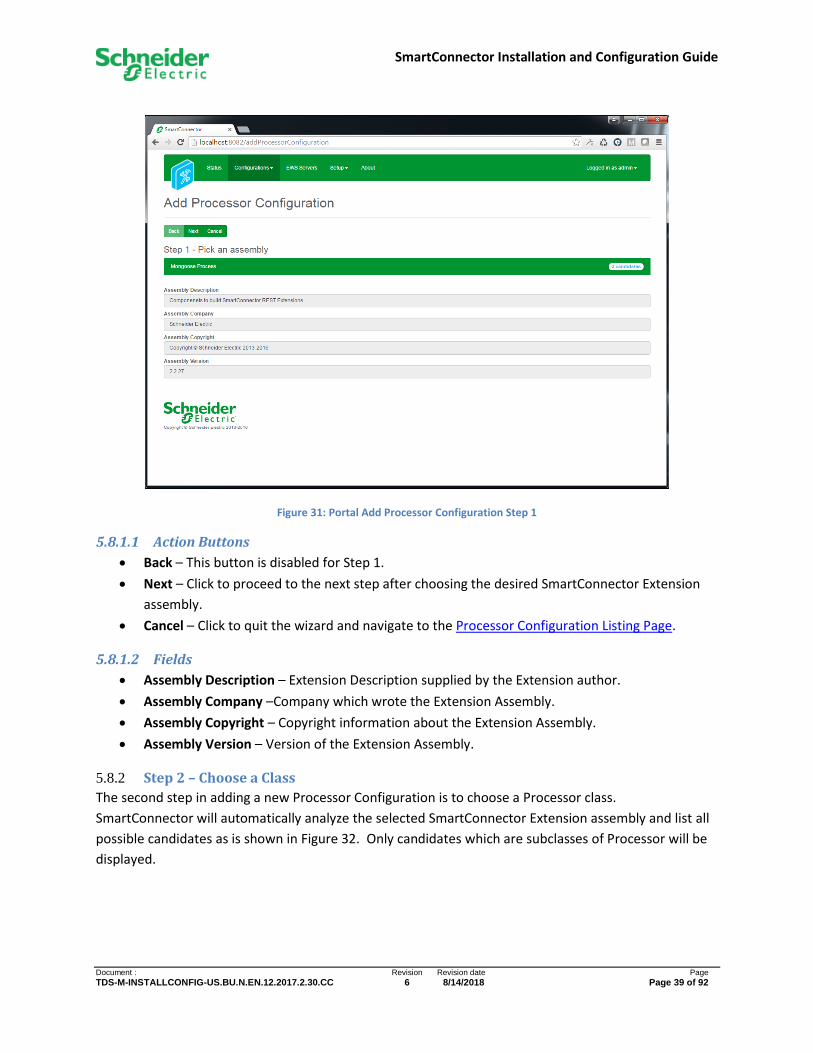
Figure 31: Portal Add Processor Configuration Step 1
5.8.1.1 Action Buttons
• Back – This button is disabled for Step 1.
• Next – Click to proceed to the next step after choosing the desired SmartConnector Extension
assembly.
• Cancel – Click to quit the wizard and navigate to the Processor Configuration Listing Page.
5.8.1.2 Fields
• Assembly Description – Extension Description supplied by the Extension author.
• Assembly Company –Company which wrote the Extension Assembly.
• Assembly Copyright – Copyright information about the Extension Assembly.
• Assembly Version – Version of the Extension Assembly.
5.8.2 Step 2 – Choose a Class
The second step in adding a new Processor Configuration is to choose a Processor class.
SmartConnector will automatically analyze the selected SmartConnector Extension assembly and list all
possible candidates as is shown in Figure 32. Only candidates which are subclasses of Processor will be
displayed.

SmartConnector Installation and Configuration Guide
Document : Revision Revision date Page
TDS-M-INSTALLCONFIG-US.BU.N.EN.12.2017.2.30.CC 6 8/14/2018 Page 40 of 92
Figure 32: Portal Add Processor Configuration Step 2
5.8.2.1 Action Buttons
• Back – Click to return to Step 1.
• Next – Click to continue configuration after selecting a Processor subclass.
• Cancel – Click to quit the wizard and navigate to the Processor Configuration Listing Page.
5.8.3 Step 3 – Name Configuration
The final step in adding a Processor Configuration is to name the configuration and provide an optional
Description as shown in Figure 33. SmartConnector will display the selections made in Step 1 and Step 2
but these are no longer editable at this point. Processors can be written to automatically seed the
Name and Descriptions with defaults that the Extension author thought would be helpful. These values
can be used as is or edited as needed.
SmartConnector Installation and Configuration Guide
Document : Revision Revision date Page
TDS-M-INSTALLCONFIG-US.BU.N.EN.12.2017.2.30.CC 6 8/14/2018 Page 41 of 92
Figure 33: Portal Add Processor Configuration Step 3
5.8.3.1 Action Buttons
• Back – Click to return to Step 2.
• Finish – Click to save the new Processor Configuration and navigate to the Processor
Configuration Detail Page for the new configuration.
• Cancel – Click to quit the wizard and navigate to the Processor Configuration Listing Page.
5.8.3.2 Fields
• Name – Descriptive name for the Processor Configuration.
• Description – Free form text field.
• Assembly File – The complete file path where the Extension Assembly is located.
• Class Name – The name of the Processor subclass configured.
5.9 Processor Configuration Detail Page
The Processor Configuration Detail Page allows the user to view and edit a Processor Configuration. The
page functions in two modes: view mode and edit mode. In View Mode, no fields are enabled for edit.
In Edit Mode, one or more fields are enabled for edit. Figure 34 shows what the Processor Configuration
Detail Page would like after adding a configuration for the sample LongRunningProcessor (see Add
Processor Configuration Page).

SmartConnector Installation and Configuration Guide
Document : Revision Revision date Page
TDS-M-INSTALLCONFIG-US.BU.N.EN.12.2017.2.30.CC 6 8/14/2018 Page 42 of 92
Figure 34: Portal Processor Configuration Page
5.9.1 Action Buttons
The action buttons available depend on the page mode and whether the Processor Configuration is
running or not.
• Edit All – Available in either mode. Click to immediately enable all writeable fields for edit. The
button will disappear after it has been clicked for the duration of edit mode.
• Start – Available in view mode only when the Processor Configuration is NOT RUNNING. Click to
add a Configuration Request to start the Processor Configuration. If the Processor Configuration
does not allow a manual Start, this button will appear disabled.
• Stop – Available in view mode only when the Processor Configuration is RUNNING. Click to add
a Configuration Request to stop the Processor Configuration. If the Processor Configuration
does not allow a manual Stop, this button will appear disabled.
• Validate – Available in view mode. Click to validate the state of the Processor Configuration. All
issues will be displayed to the user at the top of the page.
• Reset Counter – Available in view mode. Click to clear the execution counter.
SmartConnector Installation and Configuration Guide
Document : Revision Revision date Page
TDS-M-INSTALLCONFIG-US.BU.N.EN.12.2017.2.30.CC 6 8/14/2018 Page 43 of 92
• Reset Timer – Available in view mode. Click to clear the Total Execution Timer.
• Save – Available in edit mode. Click to save all changes made to the database and return the
page to view mode.
• Cancel – Available in edit mode. Click to discard all changes made and return the page to view
mode.
5.9.2 Page Layout
The page layout is divided into a top and bottom section (see Figure 34).
The top section contains the following fields.
• Name – The name of the Processor Configuration.
• Description – Longer informative description of the Processor Configuration.
• Is Active – Indicates whether the Processor Configuration can be executed. This is useful to
disable a Processor Configuration while leaving all other properties unchanged.
The bottom section is represented in a tabbed layout.
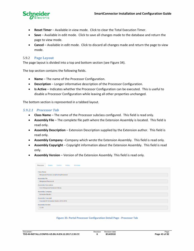
5.9.2.1 Processor Tab
• Class Name – The name of the Processor subclass configured. This field is read only.
• Assembly File – The complete file path where the Extension Assembly is located. This field is
read only.
• Assembly Description – Extension Description supplied by the Extension author. This field is
read only.
• Assembly Company –Company which wrote the Extension Assembly. This field is read only.
• Assembly Copyright – Copyright information about the Extension Assembly. This field is read
only.
• Assembly Version – Version of the Extension Assembly. This field is read only.
Figure 35: Portal Processor Configuration Detail Page - Processor Tab

SmartConnector Installation and Configuration Guide
Document : Revision Revision date Page
TDS-M-INSTALLCONFIG-US.BU.N.EN.12.2017.2.30.CC 6 8/14/2018 Page 44 of 92
5.9.2.2 Details Tab
Since the Processor which a Processor Configuration references varies, the depth and complexity of the
details also varies. Because this complexity level is not known at runtime, the Details tab is loaded only
when the user navigates to it. If you see a momentary “spinner” this is an indication that
SmartConnector is retrieving the details for the Processor Configuration. After the details have been
assembled they will be displayed in a tree format as shown in Figure 36.
The Details Tree displays all of the properties of the Processor class that the author has chosen to
expose for configuration. The meaning of these values depends on the Processor and is not known by
SmartConnector Portal. You must consult the documentation that accompanies the SmartConnector
Extension which the Processor is a part of for instructions on how to configure the specifics of a
Processor Configuration.
While the structure of details may be vary from Processor to Processor, how those details are displayed
and modified in SmartConnector Portal is consistent. Properties of a Processor can be classified into
four types; each is displayed to the user slightly differently and each has capabilities unique to it.
5.9.2.2.1 Simple Properties
Simple properties can be represented as a string, integer, Boolean, decimal, Date Time etc. The tree
node for these types of properties is shown with a leaf icon ( ). The standard editing control
consistent with the corresponding data type is displayed.
5.9.2.2.2 Complex Properties
Complex properties are those which typically contain several other Simple and/or Complex properties as
child properties. Consequently, the tree node for these types of properties is displayed as a
collapsible/expandable branch and is indicated with either the or icon: the former if the branch is
expanded and the latter if collapsed.
5.9.2.2.3 Lists Properties
List properties are collections or arrays of either Simple or Complex properties. Like a Complex
property, List Properties are shown in the tree node with or icons since these too are branch
nodes. An additional Add Button is displayed immediately adjacent to the node to indicate that
an additional child can be added to the list. Children of List Properties are always displayed with or
icons and an additional Delete Button to indicate that it can be removed.
5.9.2.2.4 Complex List Properties
A Processor Configuration property can be both a Complex Property and a List Property. For these cases
both the Add Button and Delete Button will be displayed. The function of these buttons is
as described in the appropriate section above.
SmartConnector Installation and Configuration Guide
Document : Revision Revision date Page
TDS-M-INSTALLCONFIG-US.BU.N.EN.12.2017.2.30.CC 6 8/14/2018 Page 45 of 92
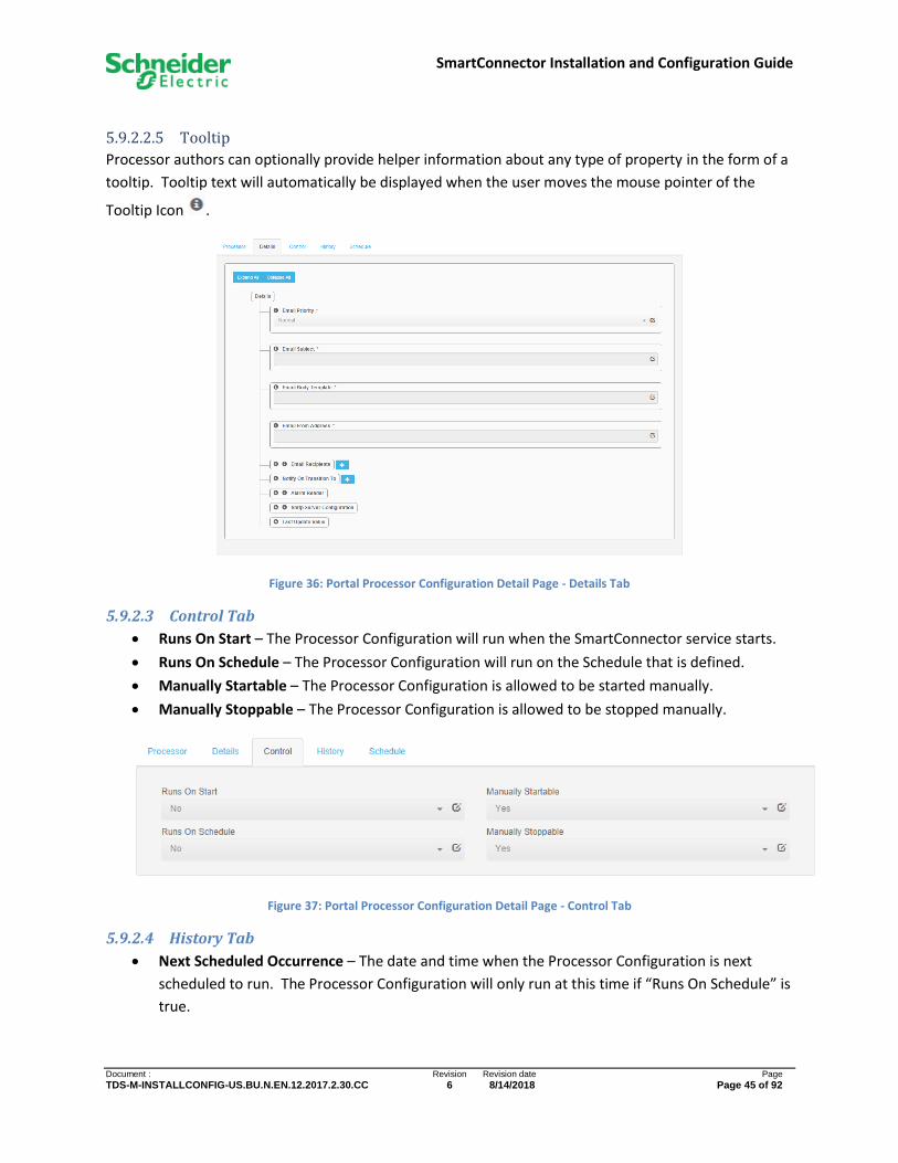
5.9.2.2.5 Tooltip
Processor authors can optionally provide helper information about any type of property in the form of a
tooltip. Tooltip text will automatically be displayed when the user moves the mouse pointer of the
Tooltip Icon .
Figure 36: Portal Processor Configuration Detail Page - Details Tab
5.9.2.3 Control Tab
• Runs On Start – The Processor Configuration will run when the SmartConnector service starts.
• Runs On Schedule – The Processor Configuration will run on the Schedule that is defined.
• Manually Startable – The Processor Configuration is allowed to be started manually.
• Manually Stoppable – The Processor Configuration is allowed to be stopped manually.
Figure 37: Portal Processor Configuration Detail Page - Control Tab
5.9.2.4 History Tab
• Next Scheduled Occurrence – The date and time when the Processor Configuration is next
scheduled to run. The Processor Configuration will only run at this time if “Runs On Schedule” is
true.
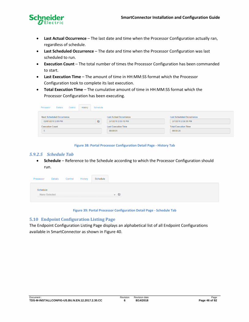
SmartConnector Installation and Configuration Guide
Document : Revision Revision date Page
TDS-M-INSTALLCONFIG-US.BU.N.EN.12.2017.2.30.CC 6 8/14/2018 Page 46 of 92
• Last Actual Occurrence – The last date and time when the Processor Configuration actually ran,
regardless of schedule.
• Last Scheduled Occurrence – The date and time when the Processor Configuration was last
scheduled to run.
• Execution Count – The total number of times the Processor Configuration has been commanded
to start.
• Last Execution Time – The amount of time in HH:MM:SS format which the Processor
Configuration took to complete its last execution.
• Total Execution Time – The cumulative amount of time in HH:MM:SS format which the
Processor Configuration has been executing.
Figure 38: Portal Processor Configuration Detail Page - History Tab
5.9.2.5 Schedule Tab
• Schedule – Reference to the Schedule according to which the Processor Configuration should
run.
Figure 39: Portal Processor Configuration Detail Page - Schedule Tab
5.10 Endpoint Configuration Listing Page
The Endpoint Configuration Listing Page displays an alphabetical list of all Endpoint Configurations
available in SmartConnector as shown in Figure 40.

SmartConnector Installation and Configuration Guide
Document : Revision Revision date Page
TDS-M-INSTALLCONFIG-US.BU.N.EN.12.2017.2.30.CC 6 8/14/2018 Page 47 of 92
Figure 40: Portal Endpoint Configuration Listing Page
5.10.1 Action Buttons
The following buttons are always available.
• Refresh – Click to refresh of the entire table.
• Add New – Click to navigate to the Add Endpoint Configuration Page.
5.10.2 Data Table
Each entry in the table contains an action toolbar, Name, URL, and Documentation URL of the Endpoint
Configuration.
The action toolbar always has four buttons. From left to right these are:
• Edit – Click to navigate to the Endpoint Configuration Detail Page.
• Clone – Click to create a complete copy of the Endpoint Configuration and navigate to the
Endpoint Configuration Detail Page for the newly cloned item.
• Delete – Click to delete the Endpoint Configuration from the database. If the Endpoint
Configuration is running it will first be stopped.
• Toggle Button – The final button is used to both convey status and action. If the action bar
contains a “Play Button” the Endpoint Configuration is NOT RUNNING. Click to add
a Configuration Request to start the Endpoint Configuration. If the action bar contains a “Stop
Button” the Endpoint Configuration is RUNNING. Click to add a Configuration
Request to stop the Endpoint Configuration.
SmartConnector Installation and Configuration Guide
Document : Revision Revision date Page
TDS-M-INSTALLCONFIG-US.BU.N.EN.12.2017.2.30.CC 6 8/14/2018 Page 48 of 92
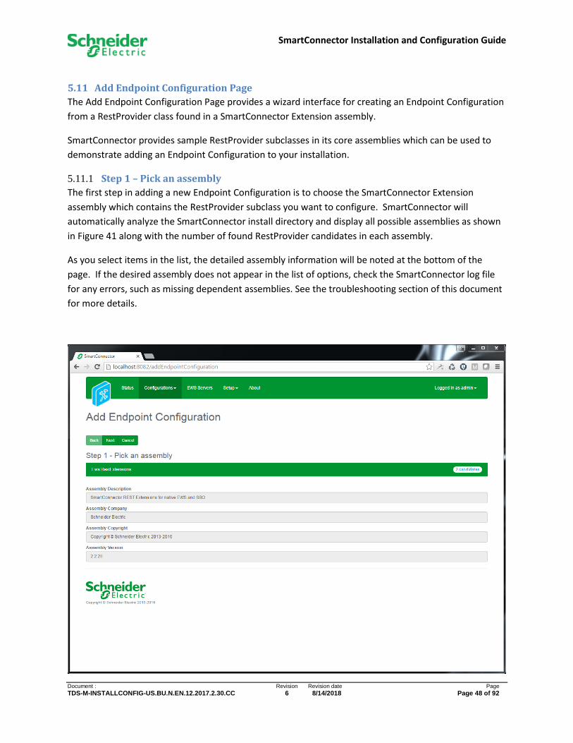
5.11 Add Endpoint Configuration Page
The Add Endpoint Configuration Page provides a wizard interface for creating an Endpoint Configuration
from a RestProvider class found in a SmartConnector Extension assembly.
SmartConnector provides sample RestProvider subclasses in its core assemblies which can be used to
demonstrate adding an Endpoint Configuration to your installation.
5.11.1 Step 1 – Pick an assembly
The first step in adding a new Endpoint Configuration is to choose the SmartConnector Extension
assembly which contains the RestProvider subclass you want to configure. SmartConnector will
automatically analyze the SmartConnector install directory and display all possible assemblies as shown
in Figure 41 along with the number of found RestProvider candidates in each assembly.
As you select items in the list, the detailed assembly information will be noted at the bottom of the
page. If the desired assembly does not appear in the list of options, check the SmartConnector log file
for any errors, such as missing dependent assemblies. See the troubleshooting section of this document
for more details.

SmartConnector Installation and Configuration Guide
Document : Revision Revision date Page
TDS-M-INSTALLCONFIG-US.BU.N.EN.12.2017.2.30.CC 6 8/14/2018 Page 49 of 92
Figure 41: Portal Endpoint Configuration Add Processor Configuration Step 1
5.11.1.1 Action Buttons
• Back – This button is disabled for Step 1.
• Next – Click to proceed to the next step after choosing the desired SmartConnector Extension
assembly.
• Cancel – Click to quit the wizard and navigate to the Endpoint Configuration Listing Page.
5.11.1.2 Fields
• Assembly Description – Extension Description supplied by the Extension author.
• Assembly Company –Company which wrote the Extension Assembly.
• Assembly Copyright – Copyright information about the Extension Assembly.
• Assembly Version – Version of the Extension Assembly.
5.11.2 Step 2 – Choose a Class
The second step in adding a new Endpoint Configuration is to choose a RestProvider class.
SmartConnector will automatically analyze the selected SmartConnector Extension assembly and list all
possible candidates as is shown in Figure 42. Only candidates which are subclasses of RestProvider will
be displayed.
Figure 42: Portal Add Endpoint Configuration Step 2
5.11.2.1 Action Buttons
• Back – Click to return to Step 1.
• Next – Click to continue configuration after selecting a RestProvider subclass.
• Cancel – Click to quit the wizard and navigate to the Endpoint Configuration Listing Page.
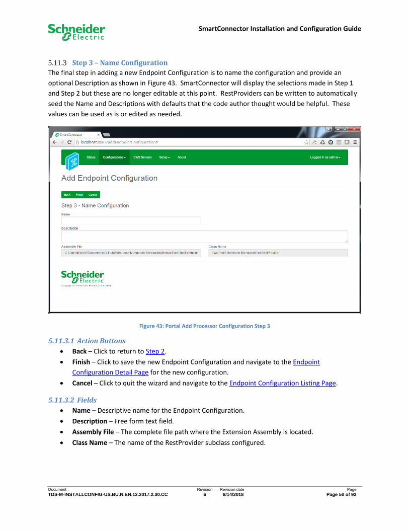
SmartConnector Installation and Configuration Guide
Document : Revision Revision date Page
TDS-M-INSTALLCONFIG-US.BU.N.EN.12.2017.2.30.CC 6 8/14/2018 Page 50 of 92
5.11.3 Step 3 – Name Configuration
The final step in adding a new Endpoint Configuration is to name the configuration and provide an
optional Description as shown in Figure 43. SmartConnector will display the selections made in Step 1
and Step 2 but these are no longer editable at this point. RestProviders can be written to automatically
seed the Name and Descriptions with defaults that the code author thought would be helpful. These
values can be used as is or edited as needed.
Figure 43: Portal Add Processor Configuration Step 3
5.11.3.1 Action Buttons
• Back – Click to return to Step 2.
• Finish – Click to save the new Endpoint Configuration and navigate to the Endpoint
Configuration Detail Page for the new configuration.
• Cancel – Click to quit the wizard and navigate to the Endpoint Configuration Listing Page.
5.11.3.2 Fields
• Name – Descriptive name for the Endpoint Configuration.
• Description – Free form text field.
• Assembly File – The complete file path where the Extension Assembly is located.
• Class Name – The name of the RestProvider subclass configured.

SmartConnector Installation and Configuration Guide
Document : Revision Revision date Page
TDS-M-INSTALLCONFIG-US.BU.N.EN.12.2017.2.30.CC 6 8/14/2018 Page 51 of 92
5.12 Endpoint Configuration Detail Page
The Endpoint Configuration Detail Page allows the user to view and edit an Endpoint Configuration. The
page functions in two modes: view mode and edit mode. In View Mode, no fields are enabled for edit.
In Edit Mode, one or more fields are enabled for edit. Figure 44 shows what the Endpoint Configuration
Detail Page would like after adding a configuration for a MongooseEwsRestProvider (see Add Endpoint
Configuration Page).
Figure 44: Portal Endpoint Configuration Page
5.12.1 Action Buttons
The action buttons available depend on the page mode and whether the Endpoint Configuration is
running or not.
• Edit All – Available in either mode. Click to immediately enable all writeable fields for edit. The
button will disappear after it has been clicked for the duration of edit mode.

SmartConnector Installation and Configuration Guide
Document : Revision Revision date Page
TDS-M-INSTALLCONFIG-US.BU.N.EN.12.2017.2.30.CC 6 8/14/2018 Page 52 of 92
• Start – Available in view mode only when the Endpoint Configuration is NOT RUNNING. Click to
add a Configuration Request to start the Endpoint Configuration.
• Stop – Available in view mode only when the Endpoint Configuration is RUNNING. Click to add a
Configuration Request to stop the Endpoint Configuration.
• Validate – Available in view mode. Click to validate the state of the Endpoint Configuration. All
issues will be displayed to the user at the top of the page.
• Save – Available in edit mode. Click to save all changes made to the database and return the
page to view mode.
• Cancel – Available in edit mode. Click to discard all changes made and return the page to view
mode.
5.12.2 Page Layout
The page layout is divided into a top and bottom section (see Figure 44).
The top section contains the following fields.
• Name – The name of the Endpoint Configuration.
• Description – Longer informative description of the Endpoint Configuration.
The bottom section is represented in a tabbed layout.
5.12.2.1 Provider Tab
• Class Name – The name of the EwsRestProvider subclass configured. This field is read only.
• Assembly File – The complete file path where the Extension Assembly is located. This field is
read only.
• Assembly Description – Extension Description supplied by the Extension author. This field is
read only.
• Assembly Company –Company which wrote the Extension Assembly. This field is read only.
• Assembly Copyright – Copyright information about the Extension Assembly. This field is read
only.
• Assembly Version – Version of the Extension Assembly. This field is read only.

SmartConnector Installation and Configuration Guide
Document : Revision Revision date Page
TDS-M-INSTALLCONFIG-US.BU.N.EN.12.2017.2.30.CC 6 8/14/2018 Page 53 of 92
Figure 45: Portal Endpoint Configuration Detail Page - Provider Tab
5.12.2.2 Details Tab
Configuration of RestProviders works in exactly the same way that Processors are configured. See
Processor Configuration Detail Page - Details Tab above for more information.
5.13 Service Settings Page
The Service Listing Page displays an alphabetical list of all settings available in SmartConnector as shown
again in Figure 46 . The page functions in two modes: view mode and edit mode. In View Mode, no
fields are enabled for edit. In Edit Mode, one or more fields are enabled for edit.

SmartConnector Installation and Configuration Guide
Document : Revision Revision date Page
TDS-M-INSTALLCONFIG-US.BU.N.EN.12.2017.2.30.CC 6 8/14/2018 Page 54 of 92
Figure 46: Portal Service Settings Page
5.13.1 Action Buttons
The action buttons available depend on the page mode.
• Refresh – Available in view mode. Click to refresh the entire table.
• Edit All – Available in either mode. Click to immediately enable all writeable fields for edit. The
button will disappear after it has been clicked for the duration of edit mode.
• Save – Available in edit mode. Click to save all changes made to the database and return the
page to view mode.
• Cancel – Available in edit mode. Click to discard all changes made and return the page to view
mode.
The contents and field descriptions are covered in Review System Settings section.
5.14 Configuration Schedule Listing Page
The Configuration Schedule Listing Page displays an alphabetical list of all Configuration Schedules
available in SmartConnector as shown in Figure 47.
5.14.1 Action Buttons
• Refresh – Click to refresh of the entire table.
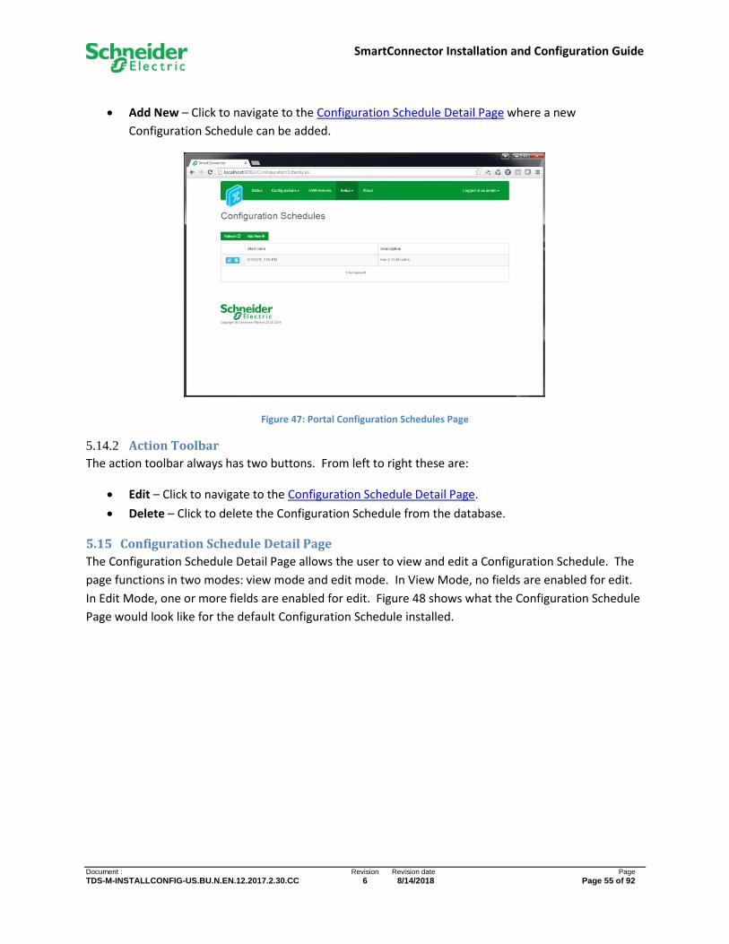
SmartConnector Installation and Configuration Guide
Document : Revision Revision date Page
TDS-M-INSTALLCONFIG-US.BU.N.EN.12.2017.2.30.CC 6 8/14/2018 Page 55 of 92
• Add New – Click to navigate to the Configuration Schedule Detail Page where a new
Configuration Schedule can be added.
Figure 47: Portal Configuration Schedules Page
5.14.2 Action Toolbar
The action toolbar always has two buttons. From left to right these are:
• Edit – Click to navigate to the Configuration Schedule Detail Page.
• Delete – Click to delete the Configuration Schedule from the database.
5.15 Configuration Schedule Detail Page
The Configuration Schedule Detail Page allows the user to view and edit a Configuration Schedule. The
page functions in two modes: view mode and edit mode. In View Mode, no fields are enabled for edit.
In Edit Mode, one or more fields are enabled for edit. Figure 48 shows what the Configuration Schedule
Page would look like for the default Configuration Schedule installed.

SmartConnector Installation and Configuration Guide
Document : Revision Revision date Page
TDS-M-INSTALLCONFIG-US.BU.N.EN.12.2017.2.30.CC 6 8/14/2018 Page 56 of 92
Figure 48: Portal Configuration Schedule Page
5.15.1 Action Buttons
• Edit All – Available in either mode. Click to immediately enable all writeable fields for edit. The
button will disappear after it has been clicked for the duration of edit mode.
• Save – Available in edit mode. Click to save all changes made to the database and return the
page to view mode.
• Cancel – Available in edit mode. Click to discard all changes made and return the page to view
mode.
5.15.2 Page Layout
The page layout depends on the value of the Type property as some properties only apply to certain
types.
The following properties are displayed for all Configuration Schedule Types:
• Description – The description of the Configuration Schedule.
• Start Date – When the Configuration Schedule will become active.
• Type – Enumeration which determines the remaining properties of the Configuration Schedule.
Possible values are: Time Interval, Weekly, and Monthly.
The following properties are displayed for all Configuration Schedule Types of Time Interval
• Interval Gap Unit – Enumeration to define the type of interval. Possible values are: Seconds,
Minutes, Hours, and Days.
• Interval Gap – Number of Interval Gap Units between occurrences of the Configuration
Schedule.

SmartConnector Installation and Configuration Guide
Document : Revision Revision date Page
TDS-M-INSTALLCONFIG-US.BU.N.EN.12.2017.2.30.CC 6 8/14/2018 Page 57 of 92
The following properties are displayed for all Configuration Schedule Types of Weekly.
• Days of the week – Multi-select to indicate which days of the week an occurrence will fall.
• Interval Gap – Number of weeks between occurrences of the Configuration Schedule.
The following properties are displayed for all Configuration Schedule Types of Monthly
• Monthly SubType – Enumeration which refines the type of monthly schedule.
• Month – Multi-select to indicate which months of the year an occurrence will fall.
• Day of the month – For SubType of “Day of the month”, this multi-select indicates which day of
the month an occurrence will fall (e.g. the 3rd of the month).
• Week of the month – For SubType of “Day of the week”, this multi-select indicates which week
of the month an occurrence will fall. This is used in conjunction with “Day of the week” (e.g. 3rd
Tuesday of the month).
• Day of the week – For SubType of “Day of the week”, this multi-select indicates which day of the
week an occurrence will fall. This is used in conjunction with “Week of the month” (e.g. 3rd
Tuesday of the month).
5.16 Processor Values Page
The Processor Values Page displays an ordered (Group) list of all values used by any Processor as shown
in Figure 49. The page functions in two modes: view mode and edit mode. In View Mode, no fields are
enabled for edit. In Edit Mode, one or more fields are enabled for edit.
5.16.1 Action Buttons
The action buttons available depend on the page mode.
• Refresh – Available in view mode. Click to refresh the entire table.
• Clear All – Available in view mode. Click to clear the value of all items in the current filtered
data set.
• Delete All – Available in view mode. Click to delete all items in the current filtered data set.
• Add New – Available in view mode. Click to insert a new Processor Value row.
• Edit All – Available in either mode. Click to immediately enable all writeable fields for edit. The
button will disappear after it has been clicked for the duration of edit mode.
• Save – Available in edit mode. Click to save all changes made to the database and return the
page to view mode.
• Cancel – Available in edit mode. Click to discard all changes made and return the page to view
mode.
5.16.2 Filtering
Because Processors can use many Processor Values in their implementations, SmartConnector provides
filtering directly in the table to facilitate finding a particular Processor Value. Filters work in a logical
“AND” fashion. They are invoked either by clicking the Refresh button or by placing the cursor in any
filter field and hitting the Enter key. All filters use “contains” logic and are case sensitive.
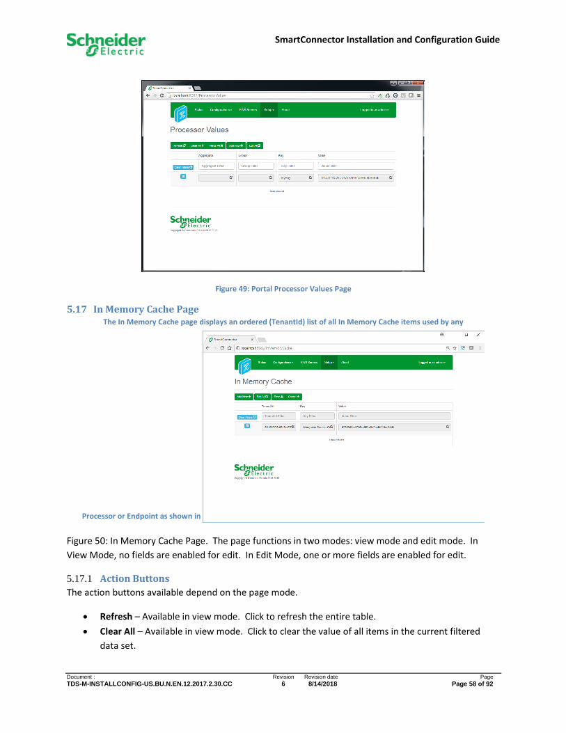
SmartConnector Installation and Configuration Guide
Document : Revision Revision date Page
TDS-M-INSTALLCONFIG-US.BU.N.EN.12.2017.2.30.CC 6 8/14/2018 Page 58 of 92
Figure 49: Portal Processor Values Page
5.17 In Memory Cache Page The In Memory Cache page displays an ordered (TenantId) list of all In Memory Cache items used by any
Processor or Endpoint as shown in
Figure 50: In Memory Cache Page. The page functions in two modes: view mode and edit mode. In
View Mode, no fields are enabled for edit. In Edit Mode, one or more fields are enabled for edit.
5.17.1 Action Buttons
The action buttons available depend on the page mode.
• Refresh – Available in view mode. Click to refresh the entire table.
• Clear All – Available in view mode. Click to clear the value of all items in the current filtered
data set.
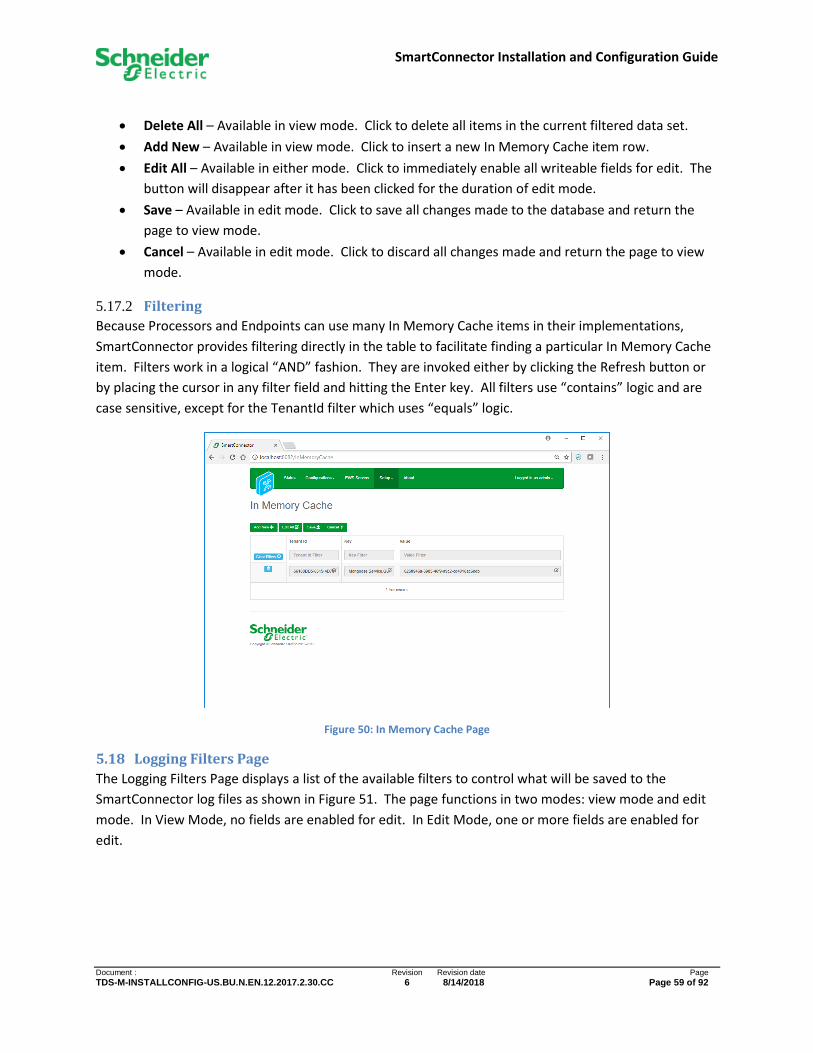
SmartConnector Installation and Configuration Guide
Document : Revision Revision date Page
TDS-M-INSTALLCONFIG-US.BU.N.EN.12.2017.2.30.CC 6 8/14/2018 Page 59 of 92
• Delete All – Available in view mode. Click to delete all items in the current filtered data set.
• Add New – Available in view mode. Click to insert a new In Memory Cache item row.
• Edit All – Available in either mode. Click to immediately enable all writeable fields for edit. The
button will disappear after it has been clicked for the duration of edit mode.
• Save – Available in edit mode. Click to save all changes made to the database and return the
page to view mode.
• Cancel – Available in edit mode. Click to discard all changes made and return the page to view
mode.
5.17.2 Filtering
Because Processors and Endpoints can use many In Memory Cache items in their implementations,
SmartConnector provides filtering directly in the table to facilitate finding a particular In Memory Cache
item. Filters work in a logical “AND” fashion. They are invoked either by clicking the Refresh button or
by placing the cursor in any filter field and hitting the Enter key. All filters use “contains” logic and are
case sensitive, except for the TenantId filter which uses “equals” logic.
Figure 50: In Memory Cache Page
5.18 Logging Filters Page
The Logging Filters Page displays a list of the available filters to control what will be saved to the
SmartConnector log files as shown in Figure 51. The page functions in two modes: view mode and edit
mode. In View Mode, no fields are enabled for edit. In Edit Mode, one or more fields are enabled for
edit.

SmartConnector Installation and Configuration Guide
Document : Revision Revision date Page
TDS-M-INSTALLCONFIG-US.BU.N.EN.12.2017.2.30.CC 6 8/14/2018 Page 60 of 92
Figure 51: Portal Logging Filters Page
5.18.1 Action Buttons
• Refresh – Available in view mode. Click to refresh the entire table.
• Edit All – Available in either mode. Click to immediately enable all writeable fields for edit. The
button will disappear after it has been clicked for the duration of edit mode.
• All – Available in either mode. Click to set all filters to included.
• None – Available in either mode. Click to set all filters to not be included.
• Save – Available in edit mode. Click to save all changes made to the database and return the
page to view mode.
• Cancel – Available in edit mode. Click to discard all changes made and return the page to view
mode.
5.19 Users Page
The Users Page displays a list of SmartConnector user credentials which are used to access the Portal as
shown in Figure 52. The current user can add new users, delete existing users, and lock/unlock another
user account. The current user cannot delete or lock their own credentials.

SmartConnector Installation and Configuration Guide
Document : Revision Revision date Page
TDS-M-INSTALLCONFIG-US.BU.N.EN.12.2017.2.30.CC 6 8/14/2018 Page 61 of 92
Figure 52: Portal Users Page
5.19.1 Action Buttons
• Refresh – Click to refresh the entire table.
• Add New – Click to navigate to the Add New User Page where a new User can be added.
5.19.2 Action Toolbar
The action toolbar always has two buttons. From left to right these are:
• Delete – Click to delete the User from the database. If the User is logged in, they will be logged
out.
• Lock – Click to lock the User from accessing the Portal. If the User is logged in, they will be
logged out and will not be able to log in again until their account is unlocked.
5.20 Add New User Page
The Add New User page allows the current user to enter new credentials and is shown in Figure 53.
5.20.1 Fields
• Username – The name of the user which will be added. This name must not be currently used
by any other user.
• Password – The password for the new user.
• Confirm Password – You must retype the password exactly the same.

SmartConnector Installation and Configuration Guide
Document : Revision Revision date Page
TDS-M-INSTALLCONFIG-US.BU.N.EN.12.2017.2.30.CC 6 8/14/2018 Page 62 of 92
Figure 53: Portal Add User Page
5.20.2 Action Buttons
• Save – Click to create a new user with the Username and Password supplied and navigate back
to the Users Page.
• Cancel – Click to abort adding a new user and navigate to the Users Page.
5.21 Change Password Page
The Change Password Page allows the current user to change their password. Passwords are required
to be at least 6 characters in length and contain a mix of upper and lower case with at least one numeric
and one non-alphanumeric character.
The following fields are available:
• Current Password – You are required to enter the password for the current user.
• New Password – The new password.
• Confirm New Password – You must retype the new password exactly the same.
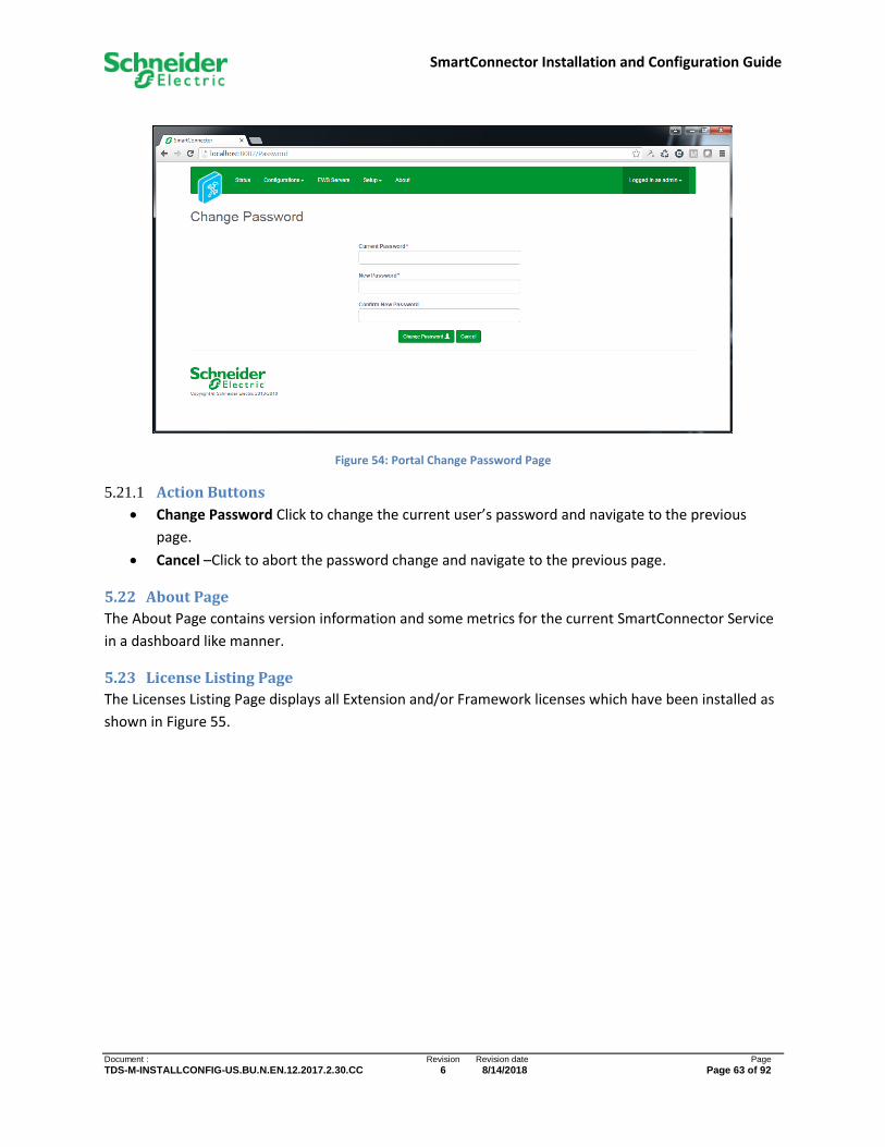
SmartConnector Installation and Configuration Guide
Document : Revision Revision date Page
TDS-M-INSTALLCONFIG-US.BU.N.EN.12.2017.2.30.CC 6 8/14/2018 Page 63 of 92
Figure 54: Portal Change Password Page
5.21.1 Action Buttons
• Change Password Click to change the current user’s password and navigate to the previous
page.
• Cancel –Click to abort the password change and navigate to the previous page.
5.22 About Page
The About Page contains version information and some metrics for the current SmartConnector Service
in a dashboard like manner.
5.23 License Listing Page
The Licenses Listing Page displays all Extension and/or Framework licenses which have been installed as
shown in Figure 55.
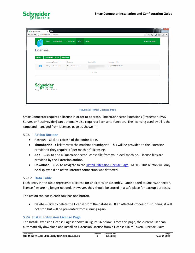
SmartConnector Installation and Configuration Guide
Document : Revision Revision date Page
TDS-M-INSTALLCONFIG-US.BU.N.EN.12.2017.2.30.CC 6 8/14/2018 Page 64 of 92
Figure 55: Portal Licenses Page
SmartConnector requires a license in order to operate. SmartConnector Extensions (Processor, EWS
Server, or RestProvider) can optionally also require a license to function. The licensing used by all is the
same and managed from Licenses page as shown in.
5.23.1 Action Buttons
• Refresh – Click to refresh of the entire table.
• Thumbprint – Click to view the machine thumbprint. This will be provided to the Extension
provider if they require a “per machine” licensing.
• Add – Click to add a SmartConnector license file from your local machine. License files are
provided by the Extension author.
• Download – Click to navigate to the Install Extension License Page. NOTE. This button will only
be displayed if an active internet connection was detected.
5.23.2 Data Table
Each entry in the table represents a license for an Extension assembly. Once added to SmartConnector,
license files are no longer needed. However, they should be stored in a safe place for backup purposes.
The action toolbar in each row has one button.
• Delete – Click to delete the License from the database. If an affected Processor is running, it will
not stop but will be prevented from running again.
5.24 Install Extension License Page
The Install Extension License Page is shown in Figure 56 below. From this page, the current user can
automatically download and install an Extension License from a License Claim Token. License Claim

SmartConnector Installation and Configuration Guide
Document : Revision Revision date Page
TDS-M-INSTALLCONFIG-US.BU.N.EN.12.2017.2.30.CC 6 8/14/2018 Page 65 of 92
Tokens are provided by the Extension provider. This page will only be available if an active internet
connection is available.
Figure 56: Portal Install Extension License Page
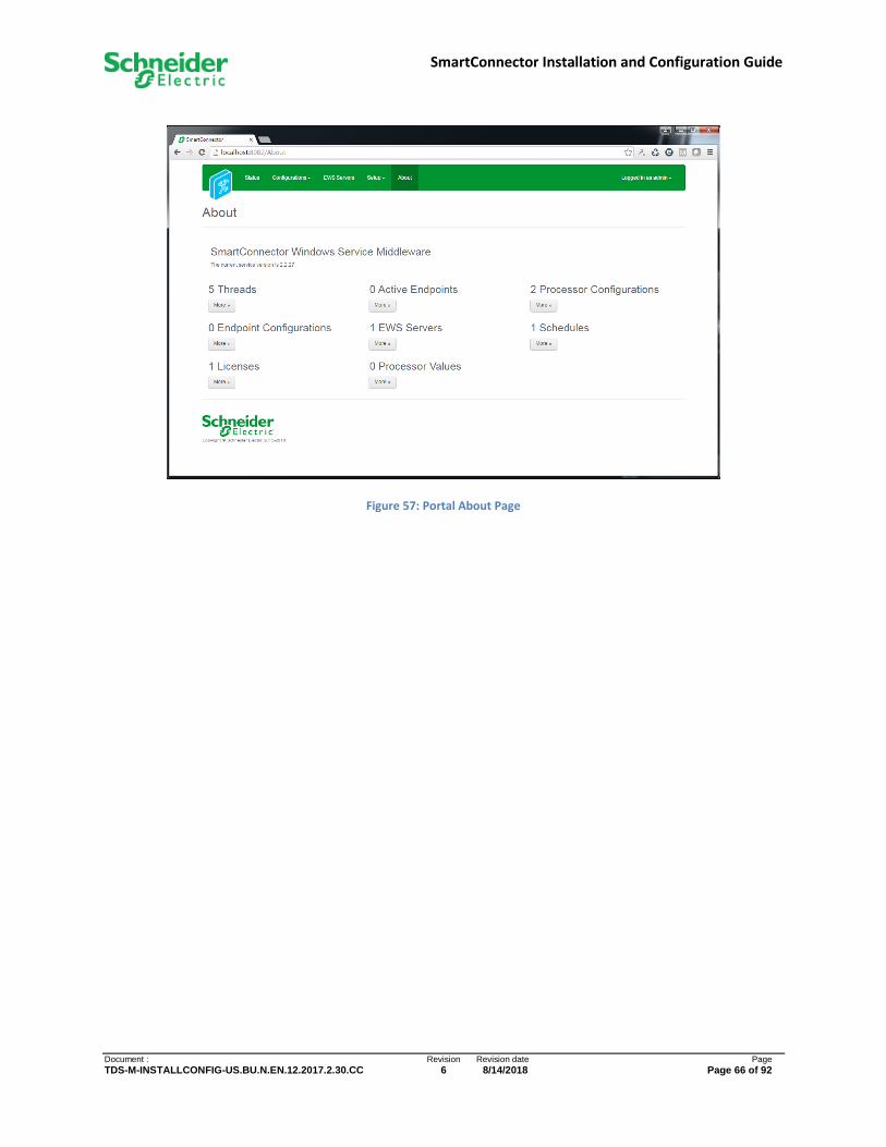
SmartConnector Installation and Configuration Guide
Document : Revision Revision date Page
TDS-M-INSTALLCONFIG-US.BU.N.EN.12.2017.2.30.CC 6 8/14/2018 Page 66 of 92
Figure 57: Portal About Page
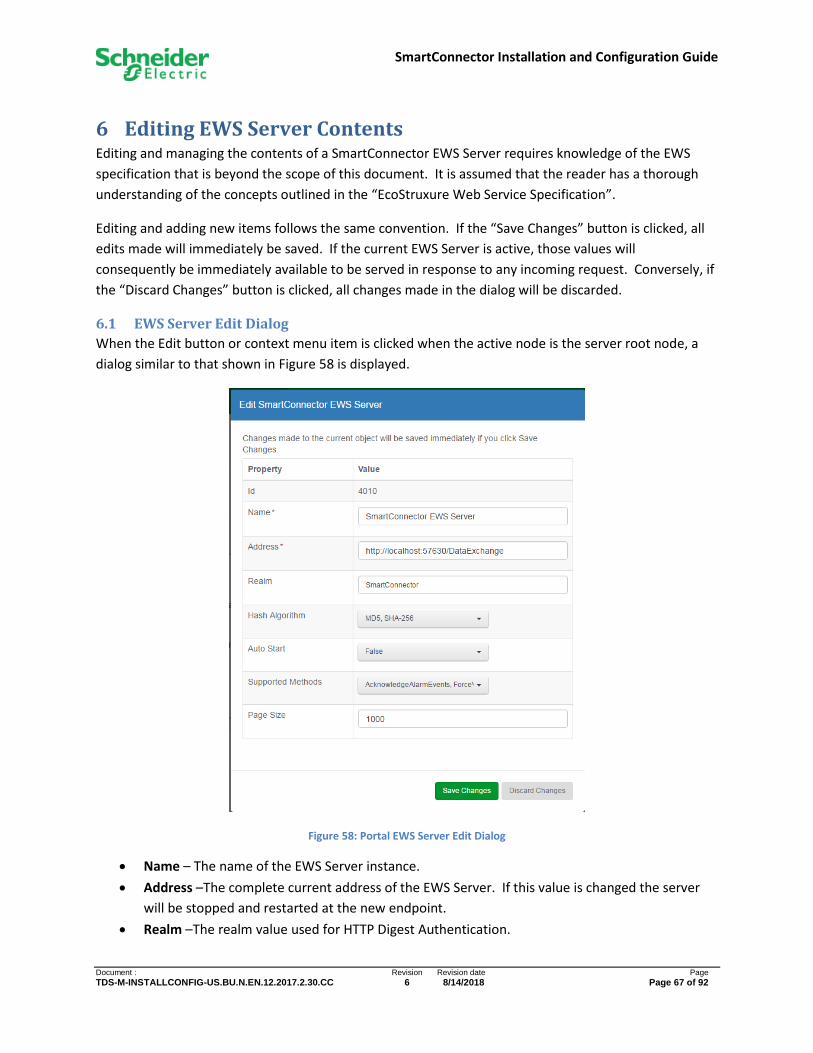
SmartConnector Installation and Configuration Guide
Document : Revision Revision date Page
TDS-M-INSTALLCONFIG-US.BU.N.EN.12.2017.2.30.CC 6 8/14/2018 Page 67 of 92
6 Editing EWS Server Contents Editing and managing the contents of a SmartConnector EWS Server requires knowledge of the EWS
specification that is beyond the scope of this document. It is assumed that the reader has a thorough
understanding of the concepts outlined in the “EcoStruxure Web Service Specification”.
Editing and adding new items follows the same convention. If the “Save Changes” button is clicked, all
edits made will immediately be saved. If the current EWS Server is active, those values will
consequently be immediately available to be served in response to any incoming request. Conversely, if
the “Discard Changes” button is clicked, all changes made in the dialog will be discarded.
6.1 EWS Server Edit Dialog
When the Edit button or context menu item is clicked when the active node is the server root node, a
dialog similar to that shown in Figure 58 is displayed.
Figure 58: Portal EWS Server Edit Dialog
• Name – The name of the EWS Server instance.
• Address –The complete current address of the EWS Server. If this value is changed the server
will be stopped and restarted at the new endpoint.
• Realm –The realm value used for HTTP Digest Authentication.
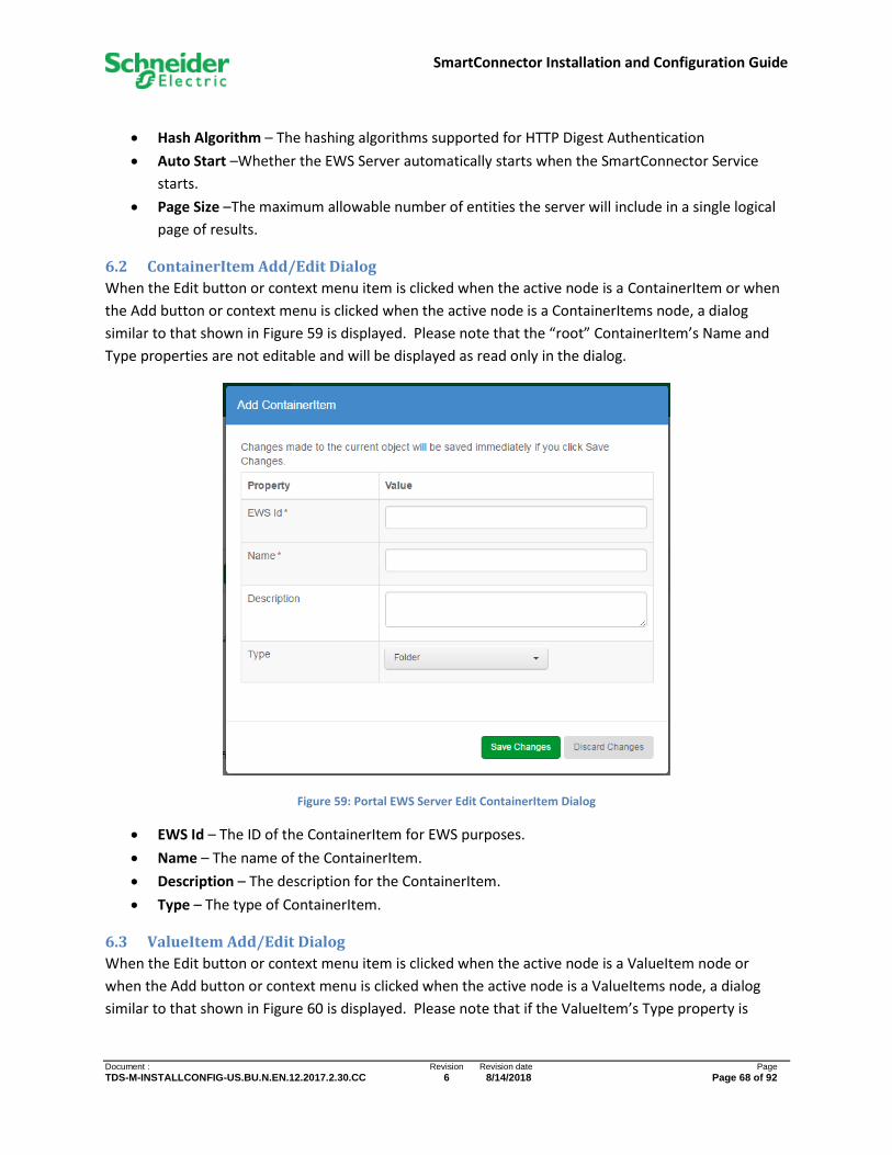
SmartConnector Installation and Configuration Guide
Document : Revision Revision date Page
TDS-M-INSTALLCONFIG-US.BU.N.EN.12.2017.2.30.CC 6 8/14/2018 Page 68 of 92
• Hash Algorithm – The hashing algorithms supported for HTTP Digest Authentication
• Auto Start –Whether the EWS Server automatically starts when the SmartConnector Service
starts.
• Page Size –The maximum allowable number of entities the server will include in a single logical
page of results.
6.2 ContainerItem Add/Edit Dialog
When the Edit button or context menu item is clicked when the active node is a ContainerItem or when
the Add button or context menu is clicked when the active node is a ContainerItems node, a dialog
similar to that shown in Figure 59 is displayed. Please note that the “root” ContainerItem’s Name and
Type properties are not editable and will be displayed as read only in the dialog.
Figure 59: Portal EWS Server Edit ContainerItem Dialog
• EWS Id – The ID of the ContainerItem for EWS purposes.
• Name – The name of the ContainerItem.
• Description – The description for the ContainerItem.
• Type – The type of ContainerItem.
6.3 ValueItem Add/Edit Dialog
When the Edit button or context menu item is clicked when the active node is a ValueItem node or
when the Add button or context menu is clicked when the active node is a ValueItems node, a dialog
similar to that shown in Figure 60 is displayed. Please note that if the ValueItem’s Type property is
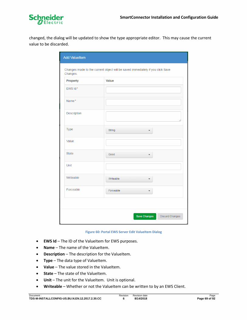
SmartConnector Installation and Configuration Guide
Document : Revision Revision date Page
TDS-M-INSTALLCONFIG-US.BU.N.EN.12.2017.2.30.CC 6 8/14/2018 Page 69 of 92
changed, the dialog will be updated to show the type appropriate editor. This may cause the current
value to be discarded.
Figure 60: Portal EWS Server Edit ValueItem Dialog
• EWS Id – The ID of the ValueItem for EWS purposes.
• Name – The name of the ValueItem.
• Description – The description for the ValueItem.
• Type – The data type of ValueItem.
• Value – The value stored in the ValueItem.
• State – The state of the ValueItem.
• Unit – The unit for the ValueItem. Unit is optional.
• Writeable – Whether or not the ValueItem can be written to by an EWS Client.

SmartConnector Installation and Configuration Guide
Document : Revision Revision date Page
TDS-M-INSTALLCONFIG-US.BU.N.EN.12.2017.2.30.CC 6 8/14/2018 Page 70 of 92
• Forceable – Whether or not the ValueItem can be forced by an EWS Client.
6.4 AlarmItem Add/Edit Dialog
When the Edit button or context menu item is clicked when the active node is an AlarmItem or when
the Add button or context menu is clicked when the active node is a AlarmItems node, a dialog similar to
that shown in Figure 61 is displayed.
Figure 61: Portal EWS Server Edit AlarmItem Dialog
• EWS Id – The ID of the AlarmItem for EWS purposes.
• Name – The name of the AlarmItem.
• Description – The description for the AlarmItem.
• Transition Model – The transition model under which AlarmEvents will be generated. Please
note that when editing an AlarmItem, the Transition Model property is read only and cannot be
changed.
• Value Item – The optional ValueItem this AlarmItem is alarming on. Please note that when
editing an AlarmItem, the ValueItem property is read only and cannot be changed.
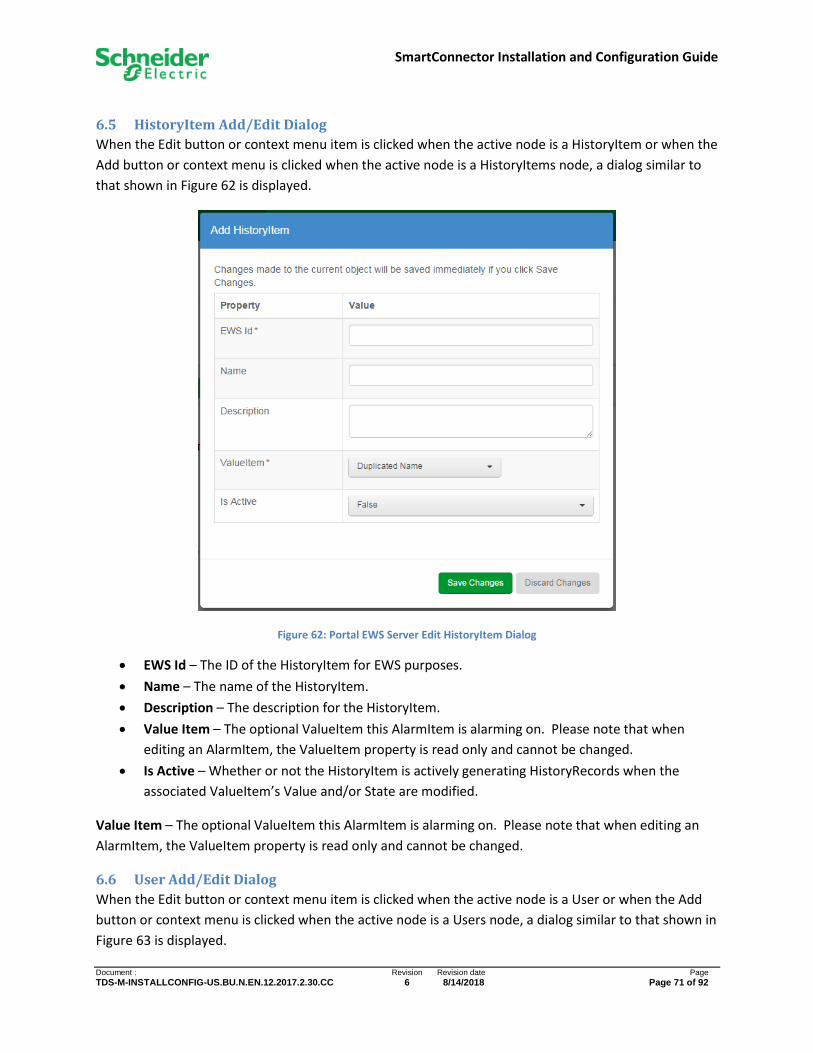
SmartConnector Installation and Configuration Guide
Document : Revision Revision date Page
TDS-M-INSTALLCONFIG-US.BU.N.EN.12.2017.2.30.CC 6 8/14/2018 Page 71 of 92
6.5 HistoryItem Add/Edit Dialog
When the Edit button or context menu item is clicked when the active node is a HistoryItem or when the
Add button or context menu is clicked when the active node is a HistoryItems node, a dialog similar to
that shown in Figure 62 is displayed.
Figure 62: Portal EWS Server Edit HistoryItem Dialog
• EWS Id – The ID of the HistoryItem for EWS purposes.
• Name – The name of the HistoryItem.
• Description – The description for the HistoryItem.
• Value Item – The optional ValueItem this AlarmItem is alarming on. Please note that when
editing an AlarmItem, the ValueItem property is read only and cannot be changed.
• Is Active – Whether or not the HistoryItem is actively generating HistoryRecords when the
associated ValueItem’s Value and/or State are modified.
Value Item – The optional ValueItem this AlarmItem is alarming on. Please note that when editing an
AlarmItem, the ValueItem property is read only and cannot be changed.
6.6 User Add/Edit Dialog
When the Edit button or context menu item is clicked when the active node is a User or when the Add
button or context menu is clicked when the active node is a Users node, a dialog similar to that shown in
Figure 63 is displayed.

SmartConnector Installation and Configuration Guide
Document : Revision Revision date Page
TDS-M-INSTALLCONFIG-US.BU.N.EN.12.2017.2.30.CC 6 8/14/2018 Page 72 of 92
Figure 63: Portal EWS Server Edit User Dialog
• Username – The name for the user.
• Password – The password for the user. The password is encrypted and will be displayed to the
user only when they navigate into the input field.
• Is Active – Whether or not an EWS client can use this User to authenticate to the EWS Server
and make requests

SmartConnector Installation and Configuration Guide
Document : Revision Revision date Page
TDS-M-INSTALLCONFIG-US.BU.N.EN.12.2017.2.30.CC 6 8/14/2018 Page 73 of 92
7 Licensing Licenses are small text files which need to be added to SmartConnector so that SmartConnector itself or
a SmartConnector Extension can be executed. Tampering with the license file in any manner will
invalidate the license. Invalid or expired licenses cannot be added to SmartConnector.
If required, a machine thumbprint may be also needed in order to generate the proper license. Please
refer to Licenses Listing Page for how to create this thumbprint.
Whether the license is for an Extension or for SmartConnector itself, the management and adding for
these licenses are handled in the same manner.
7.1 Adding Licenses
Licenses are added to SmartConnector using the Licenses Listing Page of the Portal by clicking the “Add”
button and navigating to the license file provided. Alternatively, license files can be dropped from a file
Explorer onto the grid itself.
Once added, the license file itself is no longer needed. It is recommended that the file itself be kept in a
safe place – not on the SmartConnector server itself – incase a license needs to be reinstalled.
7.2 Removing Licenses
Licenses are removed from the SmartConnector runtime by simply clicking the “Delete” button on the
applicable row of the table on the Licenses Listing Page.
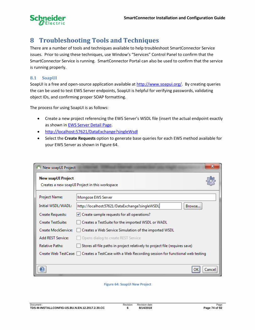
SmartConnector Installation and Configuration Guide
Document : Revision Revision date Page
TDS-M-INSTALLCONFIG-US.BU.N.EN.12.2017.2.30.CC 6 8/14/2018 Page 74 of 92
8 Troubleshooting Tools and Techniques There are a number of tools and techniques available to help troubleshoot SmartConnector Service
issues. Prior to using these techniques, use Window’s “Services” Control Panel to confirm that the
SmartConnector Service is running. SmartConnector Portal can also be used to confirm that the service
is running properly.
8.1 SoapUI
SoapUI is a free and open-source application available at http://www.soapui.org/. By creating queries
the can be used to test EWS Server endpoints, SoapUI is helpful for verifying passwords, validating
object IDs, and confirming proper SOAP formatting.
The process for using SoapUI is as follows:
• Create a new project referencing the EWS Server’s WSDL file (insert the actual endpoint exactly
as shown in EWS Server Detail Page.
• http://localhost:57621/DataExchange?singleWsdl
• Select the Create Requests option to generate base queries for each EWS method available for
your EWS Server as shown in Figure 64.
Figure 64: SoapUI New Project
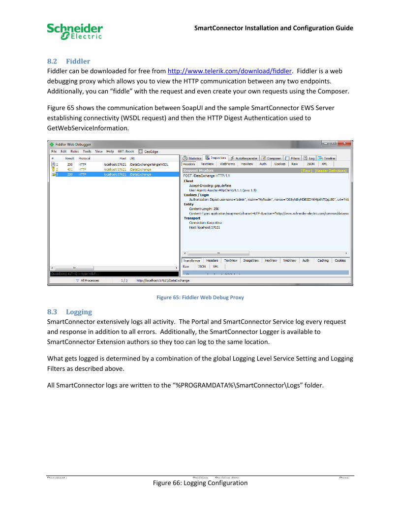
SmartConnector Installation and Configuration Guide
Document : Revision Revision date Page
TDS-M-INSTALLCONFIG-US.BU.N.EN.12.2017.2.30.CC 6 8/14/2018 Page 75 of 92
8.2 Fiddler
Fiddler can be downloaded for free from http://www.telerik.com/download/fiddler. Fiddler is a web
debugging proxy which allows you to view the HTTP communication between any two endpoints.
Additionally, you can “fiddle” with the request and even create your own requests using the Composer.
Figure 65 shows the communication between SoapUI and the sample SmartConnector EWS Server
establishing connectivity (WSDL request) and then the HTTP Digest Authentication used to
GetWebServiceInformation.
Figure 65: Fiddler Web Debug Proxy
8.3 Logging
SmartConnector extensively logs all activity. The Portal and SmartConnector Service log every request
and response in addition to all errors. Additionally, the SmartConnector Logger is available to
SmartConnector Extension authors so they too can log to the same location.
What gets logged is determined by a combination of the global Logging Level Service Setting and Logging
Filters as described above.
All SmartConnector logs are written to the “%PROGRAMDATA%\SmartConnector\Logs” folder.
Figure 66: Logging Configuration
SmartConnector Installation and Configuration Guide
Document : Revision Revision date Page
TDS-M-INSTALLCONFIG-US.BU.N.EN.12.2017.2.30.CC 6 8/14/2018 Page 76 of 92
8.4 Troubleshooting a Missing Assembly When Adding a Configuration
One can troubleshoot this issue by looking at the SmartConnector log file after trying to add a
configuration for an extension. By default, log events for the Portal are disabled and must be enabled.
Do this by changing the setting for the Portal category in the Logging Filters. Then attempt to add a
configuration.
If the desired assembly is listed, then it will load successfully. If the desired assembly is not listed, then
there is could be an issue with a missing reference. If multiple references are missing, only one
exception will be thrown and logged. Thus, add the appropriate assembly to the runtime folder and try
again to add a configuration. If not successful, repeat the above process until all referenced assemblies
are available.
If the logged exception is for a SmartConnector library, e.g. Mongoose.Process or SxL.Common, then it is
likely that the issue is related to assembly versions and strong naming. An example of such an error is
the following:
"Exceptions":[{"ClassName":"System.IO.FileLoadException","Message":"Could not load
file or assembly 'Mongoose.Process, Version=1.4.4.0, Culture=neutral,
PublicKeyToken=6e048e3a3223e3db' or one of its dependencies. The located assembly's
manifest definition does not match the assembly reference.
This issue generally refers to the scenario where the Extension assembly was compiled against a
different version of SmartConnector than what is installed. If the referenced version is prior to 2.0.0,
then the Extension will need to be re-compiled against a SmartConnector version 2.0.0 or later.
However, if the referenced version is greater than 2.2.0 but less than the installed version, then the
runtime section of the Mongoose.Service configuration file must be updated with the necessary
assembly references. For example:
<runtime>
<assemblyBinding xmlns="urn:schemas-microsoft-com:asm.v1">
<dependentAssembly>
<assemblyIdentity name="Mongoose.Process" publicKeyToken="223885051a9a1eff" culture="neutral" />
<bindingRedirect oldVersion="0.0.0.0-2.2.0.0" newVersion="2.2.0.0" />
</dependentAssembly>
<dependentAssembly>
<assemblyIdentity name="Mongoose.Common" publicKeyToken="223885051a9a1eff" culture="neutral" />
<bindingRedirect oldVersion="0.0.0.0-2.2.0.0" newVersion="2.2.0.0" />
</dependentAssembly>
<dependentAssembly>
<assemblyIdentity name="SxL.Common" publicKeyToken="223885051a9a1eff" culture="neutral" />
<bindingRedirect oldVersion="0.0.0.0-2.2.0.0" newVersion="2.2.0.0" />
</dependentAssembly>
<dependentAssembly>
<assemblyIdentity name="Ews.Common" publicKeyToken="223885051a9a1eff" culture="neutral" />
<bindingRedirect oldVersion="0.0.0.0-2.2.0.0" newVersion="2.2.0.0" />
</dependentAssembly>
<dependentAssembly>
<assemblyIdentity name="Ews.Client" publicKeyToken="223885051a9a1eff" culture="neutral" />
<bindingRedirect oldVersion="0.0.0.0-2.2.0.0" newVersion="2.2.0.0" />
</dependentAssembly>
</assemblyBinding>
</runtime>
Once these entries have been added, restart the SmartConnector service for the entries to take effect.

SmartConnector Installation and Configuration Guide
Document : Revision Revision date Page
TDS-M-INSTALLCONFIG-US.BU.N.EN.12.2017.2.30.CC 6 8/14/2018 Page 77 of 92
Note that if SmartConnector is upgraded in the future, then the oldVersion and newVersion
values must be updated to the installed SmartConnector version. Otherwise, similar
FileLoadException errors will be logged and existing configurations will not run.
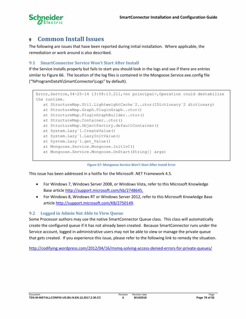
SmartConnector Installation and Configuration Guide
Document : Revision Revision date Page
TDS-M-INSTALLCONFIG-US.BU.N.EN.12.2017.2.30.CC 6 8/14/2018 Page 78 of 92
9 Common Install Issues
The following are issues that have been reported during initial installation. Where applicable, the
remediation or work around is also described.
9.1 SmartConnector Service Won’t Start After Install
If the Service installs properly but fails to start you should look in the logs and see if there are entries
similar to Figure 66. The location of the log files is contained in the Mongoose.Service.exe.config file
(“%ProgramData%\SmartConnector\Logs” by default).
This issue has been addressed in a hotfix for the Microsoft .NET Framework 4.5.
• For Windows 7, Windows Server 2008, or Windows Vista, refer to this Microsoft Knowledge
Base article http://support.microsoft.com/kb/2748645.
• For Windows 8, Windows RT or Windows Server 2012, refer to this Microsoft Knowledge Base
article http://support.microsoft.com/KB/2750149.
9.2 Logged in Admin Not Able to View Queue
Some Processor authors may use the native SmartConnector Queue class. This class will automatically
create the configured queue if it has not already been created. Because SmartConnector runs under the
Service account, logged in administrative users may not be able to view or manage the private queue
that gets created. If you experience this issue, please refer to the following link to remedy the situation.
http://codifying.wordpress.com/2012/04/16/msmq-solving-access-denied-errors-for-private-queues/
Error,Service,04-25-14 13:58:13.211,<no principal>,Operation could destabilize
the runtime.
at StructureMap.Util.LightweightCache`2..ctor(IDictionary`2 dictionary)
at StructureMap.Graph.PluginGraph..ctor()
at StructureMap.PluginGraphBuilder..ctor()
at StructureMap.Container..ctor()
at StructureMap.ObjectFactory.defaultContainer()
at System.Lazy`1.CreateValue()
at System.Lazy`1.LazyInitValue()
at System.Lazy`1.get_Value()
at Mongoose.Service.Mongoose.InitIoC()
at Mongoose.Service.Mongoose.OnStart(String[] args)
Figure 67: Mongoose Service Won't Start After Install Error

SmartConnector Installation and Configuration Guide
Document : Revision Revision date Page
TDS-M-INSTALLCONFIG-US.BU.N.EN.12.2017.2.30.CC 6 8/14/2018 Page 79 of 92
10 Updating SmartConnector
10.1 Updating SmartConnector v2.0 or Later
From time to time, updates, enhancements and/or bug fixes will be made available. This section only
pertains to updates to SmartConnector Service and not SmartConnector Extensions. Consult the
documentation supplied with your SmartConnector Extension for details on versioning and updates.
It is recommended that you backup your database prior to any upgrade to prevent the risk of data loss
resulting from a failed upgrade. This will allow restoring the original database and re-installing the prior
version of SmartConnector.
1. Run the new installer setup.exe. You will be presented with an upgrade confirmation dialog as
seen in Figure 68.
Figure 68: Installer Upgraded Confirmation Dialog
2. Click Yes.
3. You will be presented with the dialog shown in Figure 69.
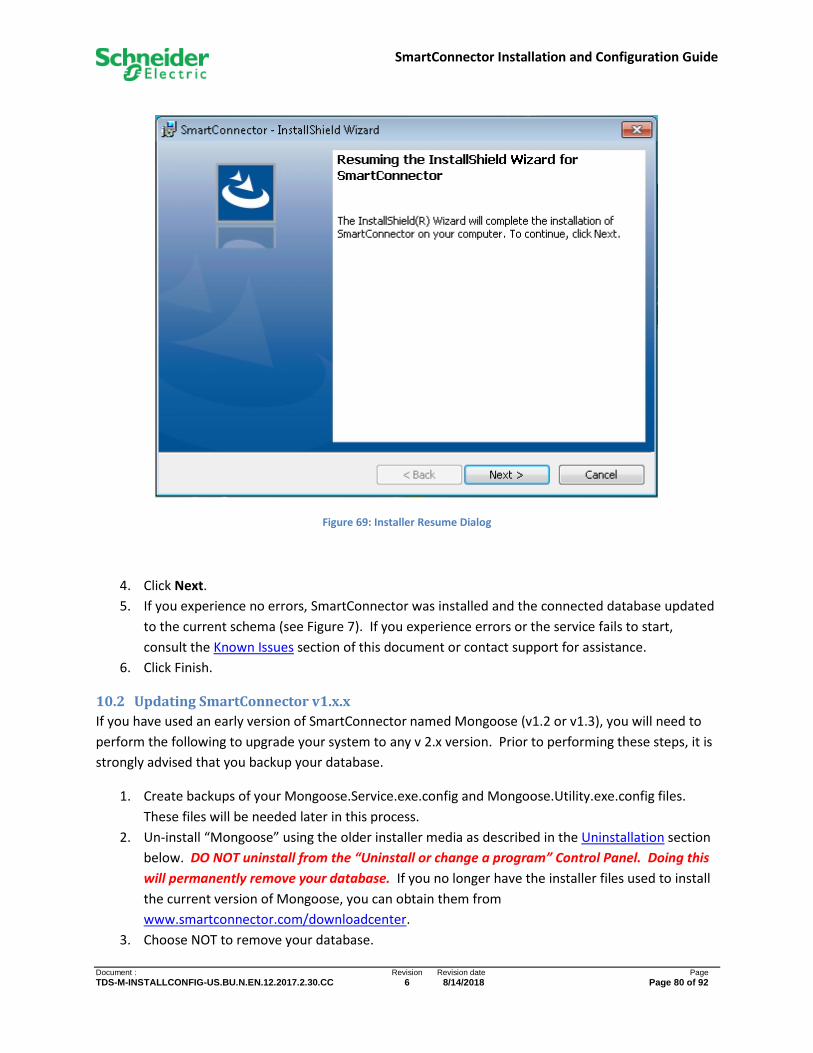
SmartConnector Installation and Configuration Guide
Document : Revision Revision date Page
TDS-M-INSTALLCONFIG-US.BU.N.EN.12.2017.2.30.CC 6 8/14/2018 Page 80 of 92
Figure 69: Installer Resume Dialog
4. Click Next.
5. If you experience no errors, SmartConnector was installed and the connected database updated
to the current schema (see Figure 7). If you experience errors or the service fails to start,
consult the Known Issues section of this document or contact support for assistance.
6. Click Finish.
10.2 Updating SmartConnector v1.x.x
If you have used an early version of SmartConnector named Mongoose (v1.2 or v1.3), you will need to
perform the following to upgrade your system to any v 2.x version. Prior to performing these steps, it is
strongly advised that you backup your database.
1. Create backups of your Mongoose.Service.exe.config and Mongoose.Utility.exe.config files.
These files will be needed later in this process.
2. Un-install “Mongoose” using the older installer media as described in the Uninstallation section
below. DO NOT uninstall from the “Uninstall or change a program” Control Panel. Doing this
will permanently remove your database. If you no longer have the installer files used to install
the current version of Mongoose, you can obtain them from
www.smartconnector.com/downloadcenter.
3. Choose NOT to remove your database.

SmartConnector Installation and Configuration Guide
Document : Revision Revision date Page
TDS-M-INSTALLCONFIG-US.BU.N.EN.12.2017.2.30.CC 6 8/14/2018 Page 81 of 92
4. Follow Installing SmartConnector Windows Service instructions, stopping after step 4.
5. At step 5, choose “Custom Installation”.
6. At step 6, de-select “Database”.
7. Complete the installation.
8. Installation should complete however since you opted to not install a database, you must now
manually update the configuration files and update the database.
9. Open a file Explorer and navigate to the installation location eg “Program Files\Schneider
Electric\Smart Connector”.
10. Open the “Mongoose.Service.exe.config” file with any text editor.
11. Locate the “EncryptionKey” setting and copy the “value” from the original configuration file you
saved in step 1.
12. Location the <connectionStrings> section.
13. Copy the contents of the same XML node from the original configuration here, overwriting the
new values.
14. Rename “MongooseDb” to “SmartConnectorDb”.
15. Rename “MongooseUserDb” to “SmartConnectorUserDb”.
16. Save the config file
17. Open “Mongoose.Utility.exe.config” file with any text editor.
18. Repeat steps 11 through 16.
19. Open a Command Prompt.
20. Navigate to the installation location eg “Program Files\Schneider Electric\Smart Connector”.
21. Run “mongoose.utility.exe /UpdateDatabase”
22. Open up the Services control panel.
23. Start the “SmartConnectorService”.
24. Verify your installation is completed. See Review Installation above.

SmartConnector Installation and Configuration Guide
Document : Revision Revision date Page
TDS-M-INSTALLCONFIG-US.BU.N.EN.12.2017.2.30.CC 6 8/14/2018 Page 82 of 92
11 Uninstallation SmartConnector can be uninstalled either from an installation distribution or from the Windows
“Uninstall or change program” Control Panel. Doing so from the latter will uninstall SmartConnector
completely including the database. If you wish to uninstall only the service, you should use the
installation media and follow the following steps.
1. Run the installer executable and confirm that you must run as an Administrator. You will be
presented with the dialog in Figure 70.
2. Click Next.
Figure 70: Installer Maintenance Welcome Dialog
3. You will be presented with the maintenance dialog shown in Figure 71.
4. Select Remove.
5. Click Next.

SmartConnector Installation and Configuration Guide
Document : Revision Revision date Page
TDS-M-INSTALLCONFIG-US.BU.N.EN.12.2017.2.30.CC 6 8/14/2018 Page 83 of 92
Figure 71: Installer Program Maintenance Dialog
6. You will be presented with the Delete SmartConnector Database dialog shown in Figure 72. If
you wish to also remove the database, check the option.

SmartConnector Installation and Configuration Guide
Document : Revision Revision date Page
TDS-M-INSTALLCONFIG-US.BU.N.EN.12.2017.2.30.CC 6 8/14/2018 Page 84 of 92
Figure 72: Installer Delete Database Dialog
7. Click Next.
8. Click Remove.
9. If you experience no errors, SmartConnector was removed and you will see the dialog shown in
Figure 73. If you experience errors or the service fails to stop, consult the Known Issues section
of this document or contact support for assistance.
SmartConnector Installation and Configuration Guide
Document : Revision Revision date Page
TDS-M-INSTALLCONFIG-US.BU.N.EN.12.2017.2.30.CC 6 8/14/2018 Page 85 of 92
Figure 73 Installer Uninstall Completed Dialog
SmartConnector Installation and Configuration Guide
Document : Revision Revision date Page
TDS-M-INSTALLCONFIG-US.BU.N.EN.12.2017.2.30.CC 6 8/14/2018 Page 86 of 92
12 Security Considerations Developing a plan for securing an integrated system requires an understanding of the unique features of
system components and technologies and their impact on overall security. This section describes
security related aspects of SmartConnector and provides best practices for security.
For more security information please refer to “EcoStruxure Web Services 1.1 Security Best Practices for
SmartStruxure Solution”.
12.1 Service Configuration File Security
The SmartConnector Service contains two application configuration (app config) files. These are
• Mongoose.Service.exe.config – Config file for the SmartConnector Service.
• Mongoose.Utility.exe.config – Config file for the Utility application which performs database
actions like creating, deleting and updating databases.
By default, these configuration files are installed in plain text. There are benefits to this; however doing
so can result in potential security vulnerabilities as both of these files contain sensitive information
needed to connect to the database and decrypt encrypted database values.
If this is deemed unacceptable for the specific installation the following steps should be taken to encrypt
both config files. This will not adversely affect the operation of SmartConnector.
NOTE: The following procedure should be repeated for each config file enumerated above.
1. Create a copy of the original file and store it off site in a secure location. Since the
SmartConnector installer creates a randomly generated encryption key for every installation,
you will never be able to reverse this process if a manual change to the configuration file is
required (such as updating the database login password) without the original unencrypted
version.
2. Verify that the service is not running or stop the SmartConnector service.
3. Rename the file to be updated to “web.config”.
4. Open a command prompt.
5. Enter the following at the command prompt replacing the placeholder with the specific path
information.
%windir%\Microsoft.NET\Framework\v2.0.50727\aspnet_regiis -pef "connectionStrings" <full path
to directory containing web.config file>
6. Press enter.
7. Repeat step 5 but replace “connectionStrings” with “appSettings”.
8. Rename the file to its original name.
When the process has been completed for both config files, restart the SmartConnector Service.
SmartConnector Installation and Configuration Guide
Document : Revision Revision date Page
TDS-M-INSTALLCONFIG-US.BU.N.EN.12.2017.2.30.CC 6 8/14/2018 Page 87 of 92
12.2 HTTP Endpoints
SmartConnector exposes multiple HTTP endpoints.
• SmartConnector Portal
• Additional endpoint for each running EWS Server
• Additional endpoint for each running REST endpoint.
The current version of SmartConnector implements user authentication on the Portal endpoint.
However, the user credentials are sent in clear text. Thus, we highly recommended securing these
endpoints via HTTPS.
Any EWS endpoint uses HTTP digest authentication, where the credentials are passed in a hash. As
such, the use of HTTPS for an EWS endpoint is not as critical as for the Portal endpoint. However, the
use of HTTPS is still considered the best practice, especially if these endpoints are made available over a
remote connection.
See the section below on how to configure HTTPS for the various SmartConnector endpoints.
12.2.1 Restricted Access through URL Conventions and Windows Firewall
The endpoint used for SmartConnector Portal defaults to http://127.0.0.1:8082. The use of the loopback
address (127.0.0.1) means that this endpoint listens only for local connections; connections from a
remote machine are not accepted. In this case, local users can ONLY use 127.0.0.1 or localhost when
connecting from a browser or any other client. Even the use of a DNS or hosts file that resolves to
127.0.0.1 will still fail.
Alternatively, SmartConnector supports the use of the “+ syntax,” e.g., http://+:8082, where the
endpoint will accept connections on all interfaces of the host computer. This configuration is more
flexible but less secure.
If SmartConnector were configured to accept remote connections as described above, one could restrict
the set of acceptable clients by configuring Windows Firewall to allow remote endpoint requests from
only desired (white-listed) IP addresses.
12.2.2 Configuring HTTPS on SmartConnector Endpoints
The procedure explained below can be applied either to the Portal, Endpoint Configuration or to any
EWS Server endpoint.
1. Obtain a certificate for the respective endpoint. This certificate can be CA-signed or self-signed.
The process to obtain a certificate is beyond the scope of this document, but one can use tools
such as OpenSSL to generate a Certificate Signing Request to submit to a Certificate Authority.
Alternatively, one can use OpenSSL to generate a self-signed certificate.
See https://www.openssl.org/docs/HOWTO/certificates.txt for more information.

SmartConnector Installation and Configuration Guide
Document : Revision Revision date Page
TDS-M-INSTALLCONFIG-US.BU.N.EN.12.2017.2.30.CC 6 8/14/2018 Page 88 of 92
2. Bundle the received certificate with the private key.
Once the signed certificate is received, this certificate must be combined with its respective
private key before installing into the Windows Certificate Store. One approach is to use a
PKCS#12 format file via OpenSSL.
For example:
openssl pkcs12 -export -out certificate.pfx -inkey privkey.pem -in certificate.crt -certfile
CAcert.pem
where:
certificate.pfx the resulting file that includes the signed certificate and the private key
privkey.pem the private key used to generate the CSR
certificate.crt the signed certificate from the CA
CAcert.pem the certificate that was used to sign the CSR.
3. Install the certificate file, i.e., certificate.pfx from the previous step, in the Windows Certificate
Store.
The certificate file should be installed in the Personal folder of the Local Computer store (not in
the Current User store). In order to do this, use the MMC (Microsoft Management Console). See
the following instructions to configure MMC to access the Local Computer store,
http://technet.microsoft.com/en-us/library/cc754431.aspx.
Figure 74: Microsoft Management Console
Depending on the format of the certificate file, an intermediate and/or root certificate may be
included in addition to the server certificate, and they may automatically be installed when
importing the file. However, if these additional certificates are needed and are not included in
the file, then they need to be explicitly installed in the appropriate folders.

SmartConnector Installation and Configuration Guide
Document : Revision Revision date Page
TDS-M-INSTALLCONFIG-US.BU.N.EN.12.2017.2.30.CC 6 8/14/2018 Page 89 of 92
4. Bind the certificate to the SmartConnector endpoint with the netsh command.
Consider the following certificate that was installed in the previous step:
Figure 75: Certificate Details
In order to create the binding, this certificate needs to be referenced via its thumbprint in the
netsh command.
For example:
netsh http add sslcert ipport=0.0.0.0:8082 certhash=
a0f4288e6f511c295362e570dcbf845c0c9247 appid={596e502c-7957-4a02-8167-716d19ced67f}
where:
ipport the IP address and port number of the endpoint, delimited by a colon
SmartConnector Installation and Configuration Guide
Document : Revision Revision date Page
TDS-M-INSTALLCONFIG-US.BU.N.EN.12.2017.2.30.CC 6 8/14/2018 Page 90 of 92
certhash the thumbprint (without whitespace) taken from the certificate properties in
the MMC
appid the value 596e502c-7957-4a02-8167-716d19ced67f, which is specific to the
SmartConnector service.
Existing bindings can be seen with the following command:
netsh http show sslcert
See http://technet.microsoft.com/en-us/library/cc725882(v=ws.10).aspx#BKMK_2 for more
information.
5. After making any changes to the certificate configuration (adding, changing or deleting a
certificate or binding), restart the SmartConnector service so that it uses the latest
configuration.
6. Verify that any HTTPS client to SmartConnector can validate the current certificate. For example,
if using a self-signed certificate, then that certificate must be installed on the client. Otherwise,
ensure that the necessary CA certificates are installed on the client so that the chain of trust can
be verified.
12.2.3 Further Hardening of the HTTPS Endpoint(s)
If a SmartConnector HTTPS endpoint is exposed to remote access, then this endpoint should be secured
based on the most recent security best-practices.
For example, in the fall of 2014, SSLv3 was found to be insecure. Windows servers, such as those hosting
SmartConnector, should have SSL v3 disabled.
More information on this specific issue can be found at: https://technet.microsoft.com/en-
us/library/security/3009008.aspx.
Further hardening practices should also be followed, such as disabling weak cipher suites. For example,
see:
http://www.dotnetnoob.com/2013/10/hardening-windows-server-20082012-and.html
https://www.owasp.org/index.php/Testing_for_Weak_SSL/TLS_Ciphers,_Insufficient_Transport_Layer_
Protection_(OTG-CRYPST-001)
http://www.bolet.org/TestSSLServer/

SmartConnector Installation and Configuration Guide
Document : Revision Revision date Page
TDS-M-INSTALLCONFIG-US.BU.N.EN.12.2017.2.30.CC 6 8/14/2018 Page 91 of 92
12.2.3.1 Configuring HTTPS for SmartConnector Extensions
Any SmartConnector extension that is configured as an HTTPS client and needs to validate a certificate
will make use of the Windows Certificate Store. Thus, any needed certificates should be installed in
respective folder of the Local Computer store using the MMC (Microsoft Management Console).
For example, self-signed certificates should be installed in the Trusted Root Certification Authorities
folder.
12.3 Logging
SmartConnector provides the ability to configure different logging levels and different log categories.
While the logging features can be very helpful to debug any issues, there are some log level and
category combinations that could represent a security vulnerability.
Specifically, the use of “All”, “Debug”, or “Trace” log levels along with logging for the Portal and API will
cause unencrypted processor configuration values to be stored in the log file. Thus, it is recommended
to not operate at “All” or “Debug” log levels unless necessary to trace a problem.
All SmartConnector logs are written to the “%PROGRAMDATA%\SmartConnector\Logs” folder on the
host system. While this folder is only writeable by an Administrator, it can be read by anyone. To
further ensure that log files are not compromised, it is advised that Read permissions on this folder are
given to only those which require it.
SmartConnector Installation and Configuration Guide
Document : Revision Revision date Page
TDS-M-INSTALLCONFIG-US.BU.N.EN.12.2017.2.30.CC 6 8/14/2018 Page 92 of 92
13 Appendix
13.1 Supported Operating Systems
The following is a list of Operating Systems which SmartConnector has been tested against. Non-listed
operating systems capable of running .NET 4.5 should also work but their compatibility has not been
verified.
• Windows 7 64 bit.
• Windows 10 64 bit.
• Windows Server 2008 64 bit.
• Windows Server 2012 64 bit.
• Windows Server 2016 64 bit.
13.2 Supported Database Servers
The following is a list of Microsoft SQL Servers which SmartConnector has been tested against. Non-
listed servers compliant with Microsoft SQL Server may also work but their compatibility is not
guaranteed.
• Local DB.
• Microsoft SQL Server 2012 Express.
• Microsoft SQL Server 2012.
• Microsoft SQL Server 2014 Express.
• Microsoft SQL Server 2014.
• Microsoft SQL Server 2016 Express.
• Microsoft SQL Server 2016.