Embed Size (px)
Citation preview

www.perfectpower.com
SMART TUNER SMT6 APPLICATION NOTES VERSION 1.1 Table of contents: Page no: SMART TUNER SMT6 IN A TURBO FUELLER APPLICATION 1 SMART TUNER SMT6 – TUNING LAMBDA 5 SMART TUNER SMT6 – IGNITION TIMING APPLICATION 9 SMT6 AND PRS – MAGNETIC PICKUP APPLICATION 11 SMART TUNER SMT6 IN A REV-GUARD APPLICATION 14 SMART TUNER (SMT6) SETPOINT CONTROL APPLICATION 16 SMART TUNER (SMT6) AIR MASS METER ADAPTION 18 SMART TUNER (SMT6) WHAT IS REQUIRED TO INSTALL AN IGNITION 25 SMART TUNER (SMT6) CALIBRATION OF AIRFLOW & TEMPERATURE SENSORS 28 SMART TUNER (SMT6) NO TUNE OPTION 32
© Digital Technology (Pty) Ltd 8 July 2002

www.perfectpower.com AN 3.1
SMART TUNER SMT6 IN A TURBO FUELLER APPLICATION Introduction: This application note describes how to use the SMT6 as a TURBO FUELLER. Abstract: A TURBO FUELLER is a device which ADDS fuel to an engine via an extra injector(s). It is applied to SUPERCHARGED and TURBOCHARGED engines alike and eliminates fuel starvation due to the increased power. History Digital Technology made the first TURBO FUELLER back in 1996. The product was called TF (4), and was (and still is) very popular with the Turbo community. The TURBO FUELLER added a new dimension to turbo charging, i.e. one could set the fuel mixture to any level, at any operating point. Before, one had to increase the fuel pressure, install bigger injectors, or install a pressure switch to operate an injector. All these methods work, somehow, but not very satisfactorily. The TURBO FUELLER took care of all problems, the engine was smooth and the fuel consumption low.
SM
ART T
UN
ER S
MT6 I
N A
TU
RBO
FU
ELL
ER A
PPLI
CATIO
N A
N 3
.1
Injector Installation The injector(s) are installed before, or after the throttle body. The best results are obtained by either:
A. Installing the injector so that it points down into the air passage. B. If this was possible, then point them “upstream” to the airflow.
Bad results (high hydrocarbons!) are obtained by spraying against the wall.
© Digital Technology (Pty) Ltd 24 October 2002 1

AN 3.1
SMT6 Installation Locate a cool dry place under the dashboard, with easy access. Make sure that you can reach the computer connector. Then wire up the unit as follows:
The AMP input (MAP in other countries) is a signal from 0-5 volts and should span the boost pressure. It can be calibrated to suit your application, and it can be read in BAR or LBS. The RPM signal can be from any pickup. It can be missing tooth wheel or any other signal. The ANALOGUE DEFLECTION input should describe the engine load. It is normally connected to a throttle sensor, but airflow or manifold pressure can be used as well. The lambda input is optional. It aids in the tuning process. If your engine is running a closed loop lambda, then you may want to run this signal through the SMT and limit the range for rich AFR’s. There are LAMBDA/AFR APPLICATION NOTES describing this operation. The MAP SWITCH is optional. It allows you to switch between TWO maps while you drive. This may be useful if bad fuel is used, or other changed engine operating conditions dictate different tuning.
© Digital Technology (Pty) Ltd 24 October 2002 2
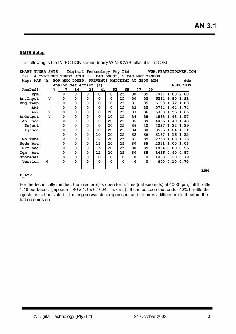
AN 3.1 SMT6 Setup The following is the INJECTION screen (sorry WINDOWS folks, it is in DOS) SMART TUNER SMT6: Digital Technology Pty Ltd WWW.PERFECTPOWER.COM Lib: 4 CYLINDER TURBO WITH 0.5 BAR BOOST, 2 BAR MAP SENSOR Map: MAP "A" FOR MAX POWER, PREVENTS KNOCKING AT 2500 RPM dds Analog deflection (%) INJECTION AnaDefl: % 7 16 28 41 53 65 77 90 Rpm: 0 0 0 0 0 25 30 35 7017 1.88 2.00 An.Input: V 0 0 0 0 0 25 30 35 6584 1.80 1.91 Eng.Temp: 0 0 0 0 0 25 31 35 6168 1.72 1.83 AMP: 0 0 0 0 0 25 32 35 5744 1.64 1.74 AFR: V 0 0 0 0 20 25 33 36 5303 1.56 1.65 AnOutput: V 0 0 0 0 20 25 34 38 4883 1.48 1.57 An. mod: 0 0 0 0 20 25 35 39 4456 1.40 1.48 Inject: 0 0 0 0 20 25 36 40 4027 1.32 1.39 Ignmod: 0 0 0 10 20 25 34 38 3595 1.24 1.31 0 0 0 10 20 25 32 36 3167 1.16 1.22 No Tune: 0 0 0 12 20 25 31 35 2738 1.08 1.13 Mode bad: 0 0 0 15 20 25 30 35 2311 1.00 1.05 RPM bad: 0 0 0 15 20 25 30 35 1884 0.80 0.96 Ign. bad: 0 0 0 12 20 25 30 35 1456 0.40 0.87 StoreSel: 0 0 0 0 0 0 0 0 1028 0.20 0.79 Version: 0 0 0 0 0 0 0 0 0 600 0.10 0.70 RPM F_AMP For the technically minded: the injector(s) is open for 5.7 ms (milliseconds) at 4000 rpm, full throttle, 1.48 bar boost. (inj open = 40 x 1.4 x 0.1024 = 5.7 ms). It can be seen that under 40% throttle the injector is not activated. The engine was decompressed, and requires a little more fuel before the turbo comes on.
© Digital Technology (Pty) Ltd 24 October 2002 3

AN 3.1 The GLOBAL SETUP SCREEN follows: SMART TUNER SMT6: Digital Technology Pty Ltd WWW.PERFECTPOWER.COM Lib: 4 CYLINDER TURBO WITH 0.5 BAR BOOST, 2 BAR MAP SENSOR Map: MAP "A" FOR MAX POWER, PREVENTS KNOCKING AT 2500 RPM dds GLOBAL PARAMETERS AnaDefl : % Rpm : Road speed div : 99 Operations mode: 10 Pos.in.pol :Y AN.Input : V Road speed limit : 0 Cylinders: 4 Pos.out.pol :Y Eng.Temp : Analog zero : 0 Teeth per rev : 2 Low levl.in : AMP : Ign. Dwell time : 0.0 Teeth per fire: 1 High freq : AFR : V Fuel upper limit : 9.99 Ign. adv.limit: 12 Low deviate. : AN. Out : V Fuel lower limit : 0.12 Ign. ret.limit: -12 Interlaced : An. Mod : Fuel freq. Limit : 7.0 KHz One Miss.T : Inject : 255 Multi coil : Ignmod : RPM limit : 6010 Nox (inject) : Temperature limit : Test dates Init. Lambda inp : No Tune : AMP limit : ____________ ____ Lambda unl : Mode bad : Deflection limit : : RPM bad : : 255 : Ign. Bad : : 255 : StoreSel: : 255 : Version : 0 : 255 : Error: Conclusion: Only the fuel was adjusted. The ignition can be adjusted with the IGNITION screen in the piggy-back mode. This allows more flexibility. The above application is easy, neat, produces a very smooth ride, and excellent fuel control. I like to run a turbo a little "rich": it is good for all components, and it doesn't reduce power.
© Digital Technology (Pty) Ltd 24 October 2002 4
www.perfectpower.com AN 3.2
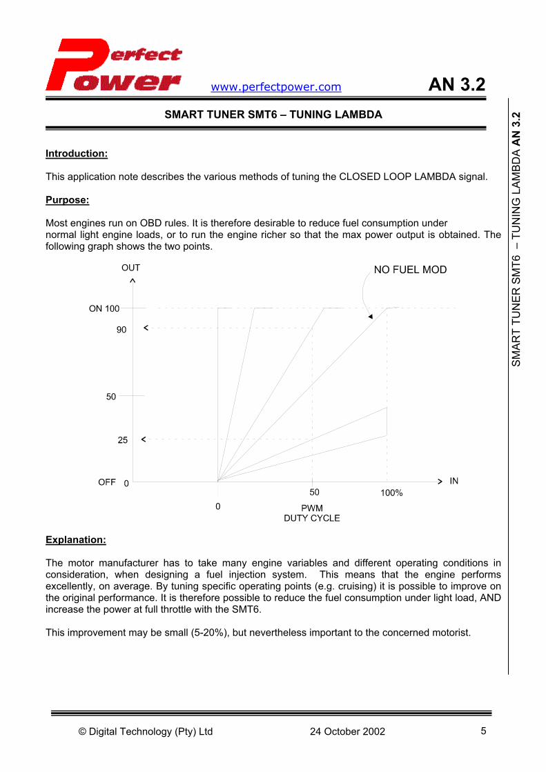
SMART TUNER SMT6 – TUNING LAMBDA Introduction: This application note describes the various methods of tuning the CLOSED LOOP LAMBDA signal. Purpose: Most engines run on OBD rules. It is therefore desirable to reduce fuel consumption under normal light engine loads, or to run the engine richer so that the max power output is obtained. The following graph shows the two points.
Explanation: The motor manufacturer has to take many engine variables and different operating conditions in consideration, when designing a fuel injection system. This means that the engine performs excellently, on average. By tuning specific operating points (e.g. cruising) it is possible to improve on the original performance. It is therefore possible to reduce the fuel consumption under light load, AND increase the power at full throttle with the SMT6.
S
MAR
T TU
NER
SM
T6 –
TU
NIN
G L
AMBD
A A
N 3
.2
This improvement may be small (5-20%), but nevertheless important to the concerned motorist.
© Digital Technology (Pty) Ltd 24 October 2002 5

AN3.2 SMT6 Features: The SMT6 has a 128 site ANALOG map, which is multiplied by a 16-step engine temperature map. The analog map sites are selected by the throttle position (or any other load signal) and the RPM. The 16 engine temperature sites are selected by the engine (or air) temperature. The SMT6 also has a LAMBDA INPUT, which is normally used for display only. It aids in the tuning process. The source of the map input can be selected, as explained in the following diagram:
It can also be seen that the SMT6 can perform 2 different signal modifications on the selected input source. Linear Modification: This type is particular interesting for small lambda modifications. It needs the analog limits to be set correctly. The following drawing explains the linear analog modification.
© Digital Technology (Pty) Ltd 24 October 2002 6
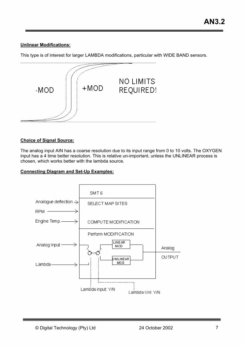
AN3.2 Unlinear Modifications: This type is of interest for larger LAMBDA modifications, particular with WIDE BAND sensors.
Choice of Signal Source: The analog input AIN has a coarse resolution due to its input range from 0 to 10 volts. The OXYGEN input has a 4 time better resolution. This is relative un-important, unless the UNLINEAR process is chosen, which works better with the lambda source. Connecting Diagram and Set-Up Examples:
© Digital Technology (Pty) Ltd 24 October 2002 7
AN3.2 The global screen has the following parameters: Lambda inp.: Y, Y=select lambda input as source Lambda unl.: Y, Y=select unlinear process for modification The ANALOG screen contains the maps. If the engine temperature is not connected then the values in the A_ENGT map must be set to 1.00 (or any other constant value!). Possibilities: RPM MAP DEFLECTION: It is possible to choose different closed loop lambda for different RPM's. THROTTLE MAP DEFLECTION: It is possible to force the engine to a lean lambda loop at partial load and to a rich loop at full throttle. ENGINE TEMPERATURE: All of the above can be influenced so that it only takes effect when the engine is warm (or cold!). Conclusion: Most of us spend 90% of the time while driving a car in the "CRUISING" mode due to speed and traffic restrictions. The SMT6 is the ideal tool to improve the cruising performance, while enhancing the power output at full throttle when overtaking. This can be done by intercepting the "CLOSED LOOP LAMBDA". The interception of the signal is not detectable!
© Digital Technology (Pty) Ltd 24 October 2002 8

www.perfectpower.com AN 3.3
SMART TUNER SMT6 – IGNITION TIMING APPLICATION Introduction: The application note describes the different methods of measuring ignition timing for a wasted spark installation. Background The wasted spark ignition method is popular because it eliminates the distributor and produces better sparks. Sometimes single coils per cylinder are fitted, which may be activated in a "wasted" fashion, or in a "sequential" way, which is normal. This "sequential" sparking is not discussed in this note, because it is normal and compatible with the conventional timing measurement. The wasted spark method fires every turn, where conventional a cylinder is fired every TWO turns. This makes the timing light reading difficult. Different timing lights A) Old fashion handheld flashlight, NO dial to adjust. No switching from 2 stroke to 4 stroke. B) Most common one: Dial to adjust flashing at TDC. No switching from 2 stroke to 4 stroke. C) Fancy one: Everything you can dream off, including 2/4 stroke switching. How Does The Dial Type Timing Light Works? At the spark it triggers a variable delay (your dialled up degrees!) and then it flashes the bulb, thus illuminating the TDC point.
The dial up delay is expressed as degrees in 360, but it is measured in the timing light as degrees in 720. A 2 stroke timing light works as follows:
SM
ART
TUN
ER S
MT6
– IG
NIT
ION
TIM
ING
APP
LIC
ATIO
N A
N 3
.3
© Digital Technology (Pty) Ltd 24 October 2002 9

AN3.3
Here the dial up delay is expressed as degrees in 360, and measured in 360 in the timing light as degrees in 360. The wasted spark firing fires every 360 degrees, but it is a 4 stroke process! So, the timing light will show wrong, if it can't be switched over to a 2 stroke measuring process. NOTE: A 4 stroke timing light with a dialup scale will show DOUBLE the actual timing if measured on a wasted spark ignition. How to Avoid Timing Light Trouble? The problem with the timing light is the "VARIABLE DELAY" or the dialup. Of course, you have no problem when the "fancy" type of timing light is used. However, all timing lights can be used with the following provisions:
A) Never use the "DIAL"! Put it to zero!
B) Engrave, scratch, or mark the pulley or the timing cover on the engine in 5, 10, 15… degree increments.
Then simply run the engine, and check which marker is showing up. Conclusion The above method of checking ignition timing is easy, and all timing lights can be used. On engines with a "flywheel window", the markings are difficult, but not impossible to read.
© Digital Technology (Pty) Ltd 24 October 2002 10

www.perfectpower.com AN 3.4
SMT6 AND PRS – MAGNETIC PICKUP APPLICATION Introduction: This application note describes how to install a magnetic pickup on an engine. Background The PERFECT POWER units can handle: Magnetic (reluctance) sensors Optical sensors Hall effect sensors The magnetic sensor is preferred by the DIY enthusiast, because it is easy to fit and available. And, it is nearly indestructible! How it works A coil is wound over a permanent magnet. Once the magnet is brought near other magnetic material (A screw head!), then the magnetic flux changes, and voltage is induced in the coil. The voltage amplitude depends on: The permanent magnet The coil construction The magnetic flux change (distance to the other magnetic material) The speed of flux change The last two items are important, because we can influence them. A magnetic pickup produces the following output voltage:
SM
T6 A
ND
PR
S –
MAG
NET
IC P
ICKU
P AP
PLIC
ATIO
N A
N 3
.4
AN3.4
© Digital Technology (Pty) Ltd 24 October 2002 11

The magnetic flux change can be produced by a "tooth", which is protruding from the other material, or a "notch" which was machined in to the material. The protruding tooth is more popular! In the following sections we talk about "teeth" only. How many magnetic pickups must be installed? In engines with a single coil and a distributor ONE pickup is required. Engines without a distributor require TWO pickups. This system is sometimes called "WASTED SPARK", because it sparks a cylinder during the exhaust stroke, and this spark is "wasted". The two pickup systems require:
A) A pickup to signal "FIRING". We call this pickup CB1.This pickup requires cylinders/2 teeth on the crank.
B) A pickup to signal "CYLINDER" information. We call this pickup CB2.
It doesn’t have to be cylinder #1. Any cylinder will do! It isn't required to be accurate, but the tooth must be BEFORE or AFTER a particular CB1 tooth. DO NOT PLACE THE CB2 PICKUP TOGETHER WITH CB1! Where to install a magnetic pickup? CB1 PICKUP: Install on the crank. On the pulley or the flywheel. Largest possible turning diameter (this gives it speed, which produces a larger signal). CB2 PICKUP: On the CAM, the distributor, the crank or pulley. Accuracy is not required, so the CAM or distributor will do fine. Interference This is a nasty thing! Interference can be produced by:
1. MECHANICAL! Wholes or other protruding magnetic materials can produce an output signal, which may trigger the unit under high RPM.
2. TEETH WITH UNEVEN HEIGHT/WIDTH. This should not happen, and a friendly machine
shop can fix it.
3. ELECTRICAL! The signal is small, and the wires should be screened, and routed away from high tension and high current wires. Do not place the pickup close to the starter motor or other magnetic devices.
4. MECHANICAL! The bracket may vibrate, thus changing the pickup clearance and the output
signal.
© Digital Technology (Pty) Ltd 24 October 2002 12
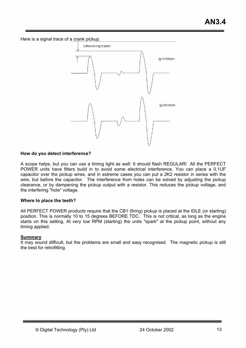
AN3.4 Here is a signal trace of a crank pickup.
How do you detect interference? A scope helps, but you can use a timing light as well: It should flash REGULAR! All the PERFECT POWER units have filters build in to avoid some electrical interference. You can place a 0.1UF capacitor over the pickup wires, and in extreme cases you can put a 2K2 resistor in series with the wire, but before the capacitor. The interference from holes can be solved by adjusting the pickup clearance, or by dampening the pickup output with a resistor. This reduces the pickup voltage, and the interfering "hole" voltage. Where to place the teeth? All PERFECT POWER products require that the CB1 (firing) pickup is placed at the IDLE (or starting) position. This is normally 10 to 15 degrees BEFORE TDC. This is not critical, as long as the engine starts on this setting. At very low RPM (starting) the units "spark" at the pickup point, without any timing applied. Summary It may sound difficult, but the problems are small and easy recognised. The magnetic pickup is still the best for retrofitting.
© Digital Technology (Pty) Ltd 24 October 2002 13

www.perfectpower.com AN 3.5
SMART TUNER SMT6 IN A REV-GUARD APPLICATION Introduction: This application note describes the use of a SMT6 in a REV-GUARD application. The SMT6 has 4 set points: A) A RPM set point B) An AMP set point C) An Engine temperature set point D) A Throttle (deflection) set point All set points operate the AUXOUT (orange wire). The AUXOUT wire is activated when the specified RPM is exceeded, provided that all other set points are disabled. It can be used to:
SM
ART
TUN
ER S
MT6
IN A
REV
-GU
ARD
APP
LIC
ATIO
N A
N 3
.5
• Disable ignition in a REV GUARD • Switch a CAM • Used to alert the driver to a gear change • Enable NOX • Any other function requiring a RPM set point VARIOUS RPM LIMITING METHODS SINGLE COIL INSTALLATION SHORTING WITH IGNITION AMPLIFIER
SMT
+_
12V
Grey/Black
E.C.U
Igni
tion
signa
l
Ignition amplifier
Yellow
Black
Green
Red
© Digital Technology (Pty) Ltd 24 October 2002 14

AN 3.5 SINGLE COIL INSTALLATION OPEN CIRCUIT WITH RELAY
SMT Grey/Black
+_
12V
E.C.U
Igni
tion
signa
l
MULTIPLE COIL INSTALLATION OPEN CIRCUIT WITH RELAY
SMT
+_
12V
Grey/Black
E.C.U
Igni
tion
signa
l
+_
12V
E.C.U
Igni
tion
signa
l
NOTE: The AUXOUT (orange wire) can only drive 0.1 Amp, which is a relay coil of 120 ohms or higher
© Digital Technology (Pty) Ltd 24 October 2002 15

www.perfectpower.com AN 3.6
SMART TUNER (SMT6) SETPOINT CONTROL APPLICATION This note describes the SETPOINT control operation of the Smart Tuner SMT6. Background A set point control does what the name implies: At a point of an input signal which can be set an output is activated. The output can have two forms:
A) ON/OFF Below the set point the output has one state; above the set point the output has the other state.
SM
ART T
UN
ER (
SM
T6)
SETU
POIN
T C
ON
TRO
L APP
LICATIO
N A
N 3
.6
B) PROPORTIONAL (PRS ONLY) At the set point the output changes slowly (proportional) its state.
The SMT6 performs the ON/OFF control, which is suited for:
- Relay activation - Nitrous activation - RPM limiting - CAM switching - Fan and water pump control - Warning - Other switching applications
SMT6 Set points The SMT6 has 4 set points: RPM setp. : 0=off, any other value active Temperature setp. : 255=off AMP setp. : 255=off Deflection setp. : 255=off The 4 set points result in ONE OUTPUT : AUXOUT (orange wire). The AUXOUT wire can handle : 0.1 Amp, max 25 volts!
© Digital Technology (Pty) Ltd 24 October 2002 16

AN 3.6
Output Switching The AUXOUT wire is switched (low, on) when ANY set point is exceeded, and is switched (high, off) when ALL input signals are BELOW the set points. Conclusion The AUXOUT set point activation is very popular, and I am sure that new applications are devised for it. The PRS system can perform the more sophisticated proportional set point control.
© Digital Technology (Pty) Ltd 24 October 2002 17

www.perfectpower.com AN 3.7
SMART TUNER (SMT6) AIR MASS METER ADAPTION This note describes ways to adapt different airflow (air mass meters) to a stock ECU via a SMART TUNER SMT5 or SMT6. Background The airflow in to an engine has to be metered so that the ECU can supply the correct fuel. Very often the stock metering device is no good, too small, or too expensive, and it must be replaced with a different unit which leads to all kind of problems. The following different air flow meters exist:
1) Analog Output Hot Wire System The air flows over a heated wire and cools it. The amount of cooling is proportional to the airflow, and the output is a "DC VOLTAGE" describing the amount of air. This unit is also called an AIR MASS METER, because it recognises the air density.
SM
ART T
UN
ER (
SM
T6)
AIR
MASS M
ETER A
DAPA
TIO
N A
N 3
.7
© Digital Technology (Pty) Ltd 24 October 2002 18

AN 3.7
2) Frequency Output Hot Wire System
Same as above, but the output is a frequency which describes the amount of airflow. This device is also called an AIR MASS METER!
3) Analog Output Mechanical Door System A trap door is placed in the airstream, and the flowing air opens the door against a spring. The degree of door movement is measured via a potentiometer and results in an analog output voltage, which is proportional to the airflow. This system relies on the spring tension and mechanical "DAMPENING", because it OVERSWINGS at acceleration.
© Digital Technology (Pty) Ltd 24 October 2002 19

AN 3.7
4) Absolute Manifold Pressure Sensor (Map, Or Amp)
This device measures the manifold pressure after the butterfly. Its output is an analog voltage. It is not directly a measurement of the airflow, but indirect the engine load can be determined from it, and the ECU can adjust the fuel accordingly.
Restrictions If your ECU requires an ANALOG airflow signal, then you need an ANALOG airflow meter. NOT the same make, but analog!
If your ECU requires a DIGITAL (FREQUENCY) airflow signal, then you can replace the existing metering device with a frequency meter ONLY.
© Digital Technology (Pty) Ltd 24 October 2002 20
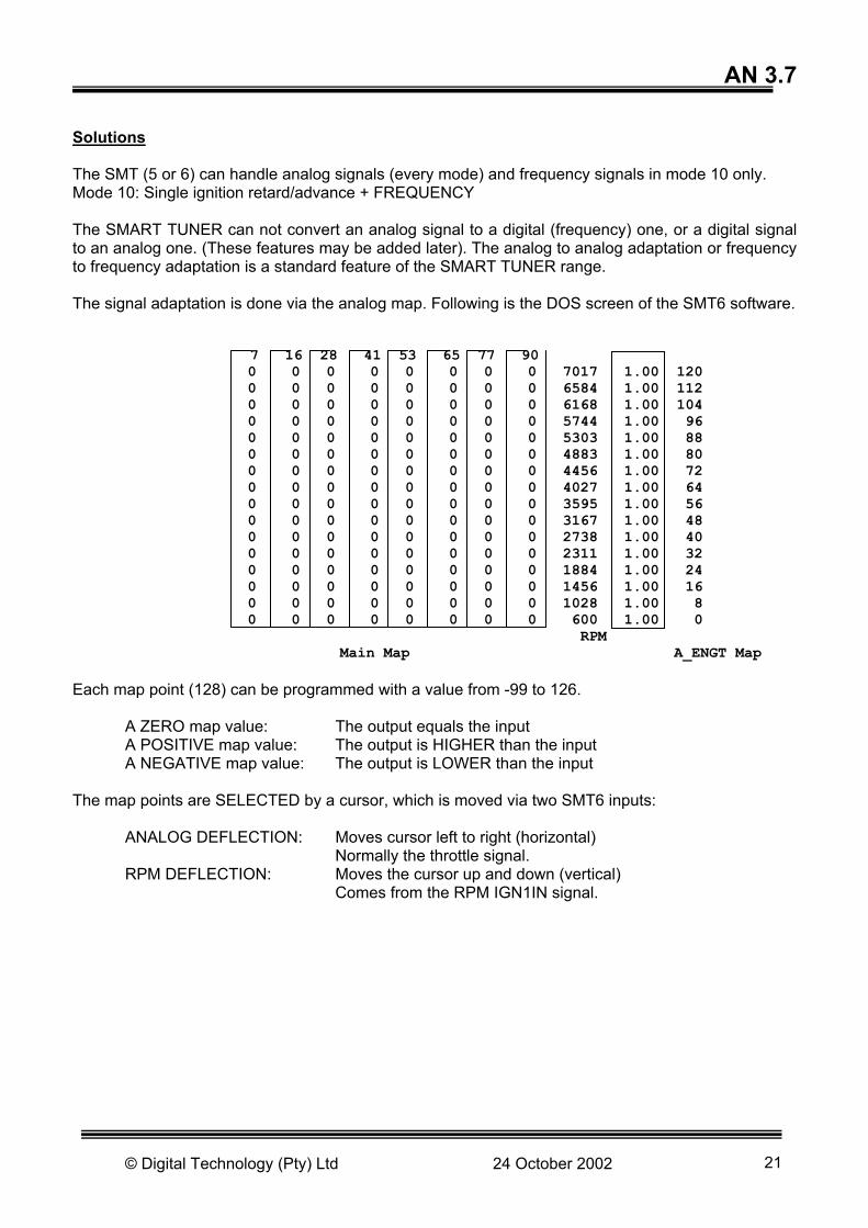
AN 3.7 Solutions The SMT (5 or 6) can handle analog signals (every mode) and frequency signals in mode 10 only. Mode 10: Single ignition retard/advance + FREQUENCY The SMART TUNER can not convert an analog signal to a digital (frequency) one, or a digital signal to an analog one. (These features may be added later). The analog to analog adaptation or frequency to frequency adaptation is a standard feature of the SMART TUNER range. The signal adaptation is done via the analog map. Following is the DOS screen of the SMT6 software. 7 16 28 41 53 65 77 90 0 0 0 0 0 0 0 0 7017 1.00 120 0 0 0 0 0 0 0 0 6584 1.00 112 0 0 0 0 0 0 0 0 6168 1.00 104 0 0 0 0 0 0 0 0 5744 1.00 96 0 0 0 0 0 0 0 0 5303 1.00 88 0 0 0 0 0 0 0 0 4883 1.00 80 0 0 0 0 0 0 0 0 4456 1.00 72 0 0 0 0 0 0 0 0 4027 1.00 64 0 0 0 0 0 0 0 0 3595 1.00 56 0 0 0 0 0 0 0 0 3167 1.00 48 0 0 0 0 0 0 0 0 2738 1.00 40 0 0 0 0 0 0 0 0 2311 1.00 32 0 0 0 0 0 0 0 0 1884 1.00 24 0 0 0 0 0 0 0 0 1456 1.00 16 0 0 0 0 0 0 0 0 1028 1.00 8 0 0 0 0 0 0 0 0 600 1.00 0 RPM Main Map A_ENGT Map Each map point (128) can be programmed with a value from -99 to 126. A ZERO map value: The output equals the input A POSITIVE map value: The output is HIGHER than the input A NEGATIVE map value: The output is LOWER than the input The map points are SELECTED by a cursor, which is moved via two SMT6 inputs: ANALOG DEFLECTION: Moves cursor left to right (horizontal) Normally the throttle signal. RPM DEFLECTION: Moves the cursor up and down (vertical) Comes from the RPM IGN1IN signal.
© Digital Technology (Pty) Ltd 24 October 2002 21

AN 3.7 For a straight adaptation, the analog deflection can be grounded and the following map will suffice: SMART TUNER SMT6: Digital Technology Pty Ltd WWW.PERFECTPOWER.COM Dscr: Map: GROUNDED DEFLECTION, SIGNAL ADAPTATION Analog deflection (%) ANALOG AnaDefl: % 7 16 28 41 53 65 77 90 Rpm: 10 0 0 0 0 0 0 0 7017 1.00 120 An Input: V 8 0 0 0 0 0 0 0 6584 1.00 112 Eng Temp: 6 0 0 0 0 0 0 0 6168 1.00 104 AMP: 4 0 0 0 0 0 0 0 5744 1.00 96 AFR: V 2 0 0 0 0 0 0 0 5303 1.00 88 AnOutput: V 0 0 0 0 0 0 0 0 4883 1.00 80 An mod: -2 0 0 0 0 0 0 0 4456 1.00 72 Inject: -4 0 0 0 0 0 0 0 4027 1.00 64 Ignmod: -6 0 0 0 0 0 0 0 3595 1.00 56 -8 0 0 0 0 0 0 0 3167 1.00 48 No Tune: -10 0 0 0 0 0 0 0 2738 1.00 40 Mode bad: -12 0 0 0 0 0 0 0 2311 1.00 32 RPM bad: -14 0 0 0 0 0 0 0 1884 1.00 24 Ign bad: -16 0 0 0 0 0 0 0 1456 1.00 16 StoreSel: -18 0 0 0 0 0 0 0 1028 1.00 8 Version: 0 -20 0 0 0 0 0 0 0 600 1.00 0 RPM A_ENGT Error: SmtLib= The numbers in the first column are the values which change the input voltage to produce a different output voltage at the indicated RPM. The numbers itself are arbitrary, they just demonstrate that at 600 RPM the output is LOWER than the input. The important thing is that the signal is tuned by the RPM, which is not necessary the right thing. If the analog deflection input is connected to the throttle, then the following map may be useful: SMART TUNER SMT6: Digital Technology Pty Ltd WWW.PERFECTPOWER.COM Dscr: Map: DEFLECTION VIA THROTTLE Analog deflection (%) ANALOG AnaDefl: % 7 16 28 41 53 65 77 90 Rpm: 8 9 10 11 12 13 14 15 7017 1.00 120 An Input: V 7 8 9 10 11 12 13 14 6584 1.00 112 Eng Temp: 6 7 8 9 10 11 12 13 6168 1.00 104 AMP: 5 6 7 8 9 10 11 12 5744 1.00 96 AFR: V 4 5 6 7 8 9 10 11 5303 1.00 88 AnOutput: V 3 4 5 6 7 8 9 10 4883 1.00 80 An mod: 2 3 4 5 6 7 8 9 4456 1.00 72 Inject: 1 2 3 4 5 6 7 8 4027 1.00 64 Ignmod: 0 1 2 3 4 5 6 7 3595 1.00 56 -1 0 1 2 3 4 5 6 3167 1.00 48 No Tune: -2 -1 0 1 2 3 4 5 2738 1.00 40 Mode bad: -3 -2 -1 0 1 2 3 4 2311 1.00 32 RPM bad: -4 -3 -6 -1 0 1 2 3 1884 1.00 24 Ign bad: -5 -4 -3 -2 -1 0 1 2 1456 1.00 16 StoreSel: -6 -5 -4 -3 -2 -1 0 1 1028 1.00 8 Version: 0 -7 -6 -5 -4 -3 -2 -1 0 600 1.00 0 RPM A_ENGT Error: SmtLib=
© Digital Technology (Pty) Ltd 24 October 2002 22

AN 3.7
This map lowers the output at 600 RPM closed throttle, but increases the output as the throttle is opened. The signal is RPM and THROTTLE tuned. Again the numbers are arbitrary, just demonstrating the principle. The next variation is only possible with an ANALOG input signal from the air metering device. If the analog deflection input is connected to the input signal then the map may look like: SMART TUNER SMT6: Digital Technology Pty Ltd WWW.PERFECTPOWER.COM Dscr: Map: DEFLECTION IS AIRFLOW SIGNAL Analog deflection (%) ANALOG AnaDefl: % 7 16 28 41 53 65 77 90 Rpm: -4 -2 0 2 4 6 8 10 7017 1.00 120 An Input: V -4 -2 0 2 4 6 8 10 6584 1.00 112 Eng Temp: -4 -2 0 2 4 6 8 10 6168 1.00 104 AMP: -4 -2 0 2 4 6 8 10 5744 1.00 96 AFR: V -4 -2 0 2 4 6 8 10 5303 1.00 88 AnOutput: V -4 -2 0 2 4 6 8 10 4883 1.00 80 An mod: -4 -2 0 2 4 6 8 10 4456 1.00 72 Inject: -4 -2 0 2 4 6 8 10 4027 1.00 64 Ignmod: -4 -2 0 2 4 6 8 10 3595 1.00 56 -4 -2 0 2 4 6 8 10 3167 1.00 48 No Tune: -4 -2 0 2 4 6 8 10 2738 1.00 40 Mode bad: -4 -2 0 2 4 6 8 10 2311 1.00 32 RPM bad: -4 -2 0 2 4 6 8 10 1884 1.00 24 Ign bad: -4 -2 0 2 4 6 8 10 1456 1.00 16 StoreSel: -4 -2 0 2 4 6 8 10 1028 1.00 8 Version: 0 -4 -2 0 2 4 6 8 10 600 1.00 0 RPM A_ENGT Error: SmtLib= Again, at very little airflow the output is lower than the input, and at high airflow the output is higher than the input. This map is deflection tuned, because the change in RPM does not change the output. Of course the numbers in the RPM rows can be tuned. In all above considerations, we left the ENGINE TEMPERATURE MAP disabled by entering a constant value. The map values in the RPM/THROTTLE map are multiplied with the values in the A_ENGT map. The engine temperature input can be connected to: ANY ANALOG VOLTAGE IN THE RANGE FROM 0 to 5 volts. Of course it can be calibrated! Connect the ENGINE TEMPERATURE INPUT to:
- ENGINE TEMPERATURE - AIR TEMPERATURE - MAP (or AMP) OUTPUT!!!!! - AIRMASS METER OUTPUT!!!!!!
All the examples above had a somewhat LINEAR result: at a particular operating point (map point) the output followed the input by the specified map value. With the introduction of the A_ENGT map, the main map values are MULTIPLIED with the A_ENGT values, which results in a "THREE DIMENSIONAL" approach, or UNLINEAR output.
© Digital Technology (Pty) Ltd 24 October 2002 23

AN 3.7
The following tuning map demonstrates a THROTTLE/RPM and ENGINE TEMP map: SMART TUNER SMT6: Digital Technology Pty Ltd WWW.PERFECTPOWER.COM Dscr: Map: THROTTLE DEFLECTION/RPM and ENGINE TEMPERATURE Analog deflection (%) ANALOG AnaDefl: % 7 16 28 41 53 65 77 90 Rpm: 8 9 10 11 12 13 14 15 7017 0.50 120 An Input: V 7 8 9 10 11 12 13 14 6584 0.50 112 Eng Temp: 6 7 8 9 10 11 12 13 6168 0.50 104 AMP: 5 6 7 8 9 10 11 12 5744 0.55 96 AFR: V 4 5 6 7 8 9 10 11 5303 0.60 88 AnOutput: V 3 4 5 6 7 8 9 10 4883 0.65 80 An mod: 2 3 4 5 6 7 8 9 4456 0.70 72 Inject: 1 2 3 4 5 6 7 8 4027 0.75 64 Ignmod: 0 1 2 3 4 5 6 7 3595 0.80 56 -1 0 1 2 3 4 5 6 3167 0.85 48 No Tune: -2 -1 0 1 2 3 4 5 2738 0.90 40 Mode bad: -3 -2 -1 0 1 2 3 4 2311 0.95 32 RPM bad: -4 -3 -2 -1 0 1 2 3 1884 1.00 24 Ign bad: -5 -4 -3 -2 -1 0 1 2 1456 1.00 16 StoreSel: -6 -5 -4 -3 -2 -1 0 1 1028 1.00 8 Version: 0 -7 -6 -5 -4 -3 -2 -1 0 600 1.00 0 RPM A_ENGT Error: SmtLib= At 600 RPM, the output signal is always LESS than the input. However, as the engine temperature increases, the output signal increases at idle. At high engine temperatures, the main map modifications are only HALF (0.5!) as effective as at lower temperatures. The above example may not be that practical. The real practical application depends on what YOUR engine needs. The signal adaptation is relative easy. If your engine requires temperature adjustment, then the A_ENGT map is good. If you engine requires ABSOLUTE PRESSURE (not manifold!) adjustment, then connect a pressure sensor to the engine temperature input and calibrate it accordingly. The calibration, setting of modes, and all other operations of the SMART TUNER are explained in the
© Digital Technology (Pty) Ltd 24 October 2002 24

www.perfectpower.com AN 3.8
SMART TUNER (SMT6) WHAT IS REQUIRED TO INSTALL AN IGNITION This note describes the items you need to watch before deciding on an ignition system. The ignition tuning or installation is not explained. Background: An ignition system consists basically of the following parts: A pickup (or two) This is required to signal the crank angle, and sometimes the next cylinder. An ignition mapping device (a box) The "black" box. It decides when to trigger a spark, what dwell angle to use, and other items
which influence the ignition. An ignition amplifier, or trigger box
This device is sometimes built-in to the mapping device, sometimes it is separate. It "amplifies" the trigger signal to a hefty current.
A coil or multiple coils They come in all shapes: Single coil (for distributor) Single coil, but two spark connections (for wasted spark) Multiple coil packs (multiple of above) Coil per cylinder Considerations: This section explains what the PRS range of engine management systems can do. The SMT6 can handle simple ignition solutions, and some of the items relevant to the SMT6 are indicated.
SM
ART T
UN
ER (
SM
T6)
WH
AT I
S R
EQ
UIR
ED
TO
IN
STALL
AN
IG
NIT
ION
AN
. 3
.8
HERE WE GO!
© Digital Technology (Pty) Ltd 24 October 2002 25

Pickup: All systems require a "UNIFORM" pickup track. That is the amount of teeth (or wholes, or gaps) the pickup is pointing at must be uniform distributed over one crank revolution. The exception is a "MISSING TOOTH" wheel, which all units can accept. The following drawings show the electrical signal resulting from the pickup. For the "blips" shown you can substitute a "square wave”, which is the result of an optical or hall sensor. The pickup signal "strength" (amplitude) must be more than 3 volts at cranking.
A second pickup is required if more than one "blip" is present per firing, and if a "wasted spark" method is used. The same applies to direct firing (one coil per cylinder), which is handled the same as wasted spark. Ignition Mapping Device: That’s the box! It must change the ignition according to the following inputs: RPM: More advance is required at high RPM Manifold pressure: If you have manifold pressure, then use it as vacuum advance.
Throttle position: If you have no manifold pressure, then you need throttle position. If you have both then you are ok.
Engine temperature: You need more advance when cold. Boost pressure: You may want to retard under extreme boost. All PERFECT POWER units can handle the above inputs, and adjust the ignition accordingly. Of course, you can adjust everything to suit your installation.
© Digital Technology (Pty) Ltd 24 October 2002 26
AN 3.8
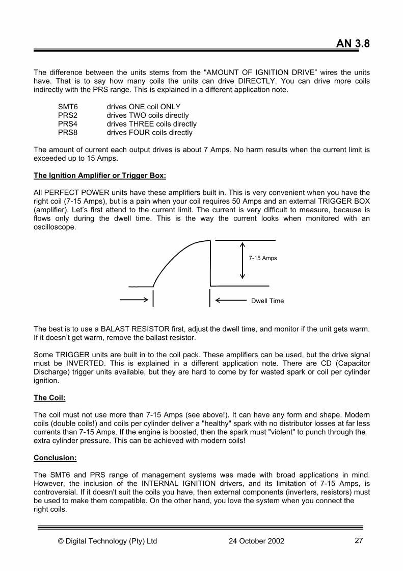
The difference between the units stems from the "AMOUNT OF IGNITION DRIVE” wires the units have. That is to say how many coils the units can drive DIRECTLY. You can drive more coils indirectly with the PRS range. This is explained in a different application note. SMT6 drives ONE coil ONLY PRS2 drives TWO coils directly PRS4 drives THREE coils directly PRS8 drives FOUR coils directly The amount of current each output drives is about 7 Amps. No harm results when the current limit is exceeded up to 15 Amps. The Ignition Amplifier or Trigger Box: All PERFECT POWER units have these amplifiers built in. This is very convenient when you have the right coil (7-15 Amps), but is a pain when your coil requires 50 Amps and an external TRIGGER BOX (amplifier). Let’s first attend to the current limit. The current is very difficult to measure, because is flows only during the dwell time. This is the way the current looks when monitored with an oscilloscope.
The best is to use a BALAST RESISTOR first, adjust the dwell time, and monitor if the unit gets warm. If it doesn’t get warm, remove the ballast resistor. Some TRIGGER units are built in to the coil pack. These amplifiers can be used, but the drive signal must be INVERTED. This is explained in a different application note. There are CD (Capacitor Discharge) trigger units available, but they are hard to come by for wasted spark or coil per cylinder ignition. The Coil: The coil must not use more than 7-15 Amps (see above!). It can have any form and shape. Modern coils (double coils!) and coils per cylinder deliver a "healthy" spark with no distributor losses at far less currents than 7-15 Amps. If the engine is boosted, then the spark must "violent" to punch through the extra cylinder pressure. This can be achieved with modern coils! Conclusion: The SMT6 and PRS range of management systems was made with broad applications in mind. However, the inclusion of the INTERNAL IGNITION drivers, and its limitation of 7-15 Amps, is controversial. If it doesn't suit the coils you have, then external components (inverters, resistors) must be used to make them compatible. On the other hand, you love the system when you connect the right coils.
© Digital Technology (Pty) Ltd 24 October 2002 27

www.perfectpower.com AN 3.10
SMART TUNER (SMT6) CALIBRATION OF AIRFLOW & TEMPERATURE SENSORS Calibration of airflow and temperature sensors The principles in this application note hold true in both the SMT and PRS range of products. The PRS and the SMT units are all about sensor readings, if you have the correct signal it does not matter where it comes from the unit will read it. We can claim that these units are compatible with such a wide range of sensors for two reasons:
1) Most sensors have an analog range between 0-5V, with exception of the frequency-based signals.
2) In both units we can calibrate the software to read a portion of the 0-5V range, it makes better sense do adjust the sensor range to read between 2-3V if the sensor being used only moves between 2-3V.
It is the ability to calibrate the curves that gives it flexibility but we have found that it is also a bit difficult to understand, hence this application note. Diagrams The following diagrams show the installation of Perfectpower temperature and airflow sensors, diagrams for other types of sensors can be found in the PRS development manual.
S
MART T
UN
ER (
SM
T6)
CALI
BRATIO
N O
F AIR
LFO
W &
TEM
PREATU
RE S
EN
SO
RS A
N 3
.10
Map Sensor Wiring
Black
Yellow
Black / Red
Map Sensor
Grnd
Signalin
+12V
PRS/SMT
© Digital Technology (Pty) Ltd 24 October 2002 28

PRS/SMT
Sensor NTC
+ 5
1k2
Temperature sensor wiring.
Signal in
Software calibration PRS units have a unique feature used for calibration of sensors, you can save the curve of a sensor alone and load them without affecting the other settings of the unit, so this would be the simplest way to setup a sensor, simply wire it in and load the file. The file names of the Perfect Power sensors are, 15AMP.PRS, 25AMP.PRS and TEMP.PRS and can be found on the development cd. We should be implementing this in the SMT6 as well soon. Temperature sensors can be calibrated to measure degrees Celsius, Fahrenheit or even Kelvin, you could even get them to read peanuts if you want, what you will understand at the end of this application note is that it is the voltage that is important the number on the display is just a number. The same is true for the airflow sensor. There are two ways of calibrating the sensors: Method 1: To calibrate the sensors using this method you need two points, a low value and a high value. Both units use the same command to calibrate sensors, AL and AH for airflow sensors and TL and TH for temperature sensors. The commands with L’s are the lower settings while the commands with H’s are the upper settings, a typical setting for the lower settings of an airflow sensor would be: AL 0 0.2 20 I will explain what this means now. AL <Grid position> <display value> <voltage> Grid position: Grid position is the first step, if you go to one of the map screens you will see that the temp sensor and airflow sensor is a coulomb of 16 steps. This is the grid position, they start at 0 and end at 15 (zero is included as a number), in the example we would be calibrating the bottom most point on the grid.
© Digital Technology (Pty) Ltd 24 October 2002 29

Display value: What I said about this value not being important is not strictly true, its not important to the unit itself but for you as the tuner its is important because it is what you want to read, so you need to match the value you intend to put here with the correct voltage on the sensor, more on this later. Voltage: I will try not to get to technical in this next bit, but like I mentioned before the PRS/SMT reads these sensors over a range of 0-5V, this range is split up by the processor into segments, like pieces of a pie, of 256 steps. If this is confusing all you really need to know is that every value of one represents 19mV. So in the example above we have set the bottom point of the graph to display 0.02 (bar or whatever) at a voltage of (19mV x 20) 380mV. Next set the high point, the same rules apply: AH 14 0.09 220 Point 14 (second from the top) of the airflow graph shows 0.09 for a voltage of 4,18V, the software will then fill in all the points between, above and below these points. I don’t know of any other method of finding these two points on a airflow sensors other than finding its data sheet and looking it up on the voltage curve, you can send this curve to our technical desk at [email protected] if you need help setting this up. For the temperature sensor this is a little different, same as with the amp sensor you can get these points on the data sheet. Another option is to calibrate it with hot and cold water. Connect the sensor to the unit as in the diagrams, supply power to the unit, place a multimeter across the sensor, put the sensor into cold water, use a thermometer to read water temperature and read the voltage on the multimeter to find its corresponding voltage. Do the same with the hot water and you will have your two voltage points as well as there corresponding temperatures on the thermometer. One thing to note is that with temperature sensors you will find that voltage decreases as temperature increases, unlike the airflow sensors where voltage increases as pressure increases, this is not a problem for our systems but something to bear in mind when calibrating. To avoid confusion this means that for a temperature sensor your high point on the grid will be a low voltage and your low point on the grid will be a high voltage. Example: TL 0 –12 220 TH 15 120 20 Means that the bottom of the grid displays –12 at a voltage of 4,18V and the top of the grid has 120 for 0.38V.
© Digital Technology (Pty) Ltd 24 October 2002 30

Method 2: For this method all you need is one single point, in this example I will be talking about temperature but the same principle holds true for airflow. Let us say you have a temperature sensor connected to the unit and you know what reading it should have in degrees Celsius, say this value is 25°C and you want the grid to have 25°C in the 4th slot of the grid (remember 0 is a valid number) then you would type: TL 3 25 The software will automatically match the voltage it is reading with 25°C and fill in the values above and below it. The advantage of this method is that it is a lot easier to use, but the disadvantage is you don’t have full control of the voltage range on the points on the grid, which you had in method one. Conclusion Windows software should be coming out with a graphical method of calibration that will be a lot easier to use, but because of the dos recognition in windows the above methods will work in windows software as well.
© Digital Technology (Pty) Ltd 24 October 2002 31

www.perfectpower.com AN 3.11
© Digital Technology (Pty) Ltd 24 October 2002 32
SMART TUNER (SMT6) NO TUNE OPTION Introduction Users of the old SMT5 units will know how much of a pain the old library system was, in the SMT6 you have only 1 option, the no-tune option. The no-tune option blanks all settings on the unit, including the global settings, they cannot be changed and they cannot be seen. Procedure
1) To enable the no-tune option the no-tune option is enabled in the configuration file of the tuning software.
2) If a unit is in no tune mode it is because the no-tune option was enabled by the tuning software, it is not because of the unit, it is because of the tuning software itself.
3) When tuning the unit run the software with the no-tune option enabled. 4) Once you have finished tuning save your settings. 5) Enable the no-tune option in the configuration file. 6) Once a download command is sent to the unit the no-tune is enabled, settings will be hidden
when the tuning software is loaded again. 7) If you want to correct the settings in a unit, run the tuning software again with the no-tune
option disabled. Then load your saved file.
SM
ART T
UN
ER (
SM
T6)
NO
TU
NE O
PTIO
N A
N 3
.11
A batch file with two separate cfg files is available, email technical.