Embed Size (px)
Citation preview
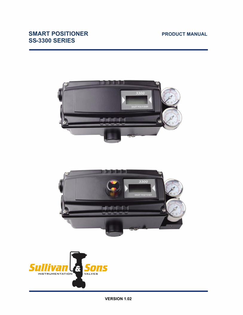
SMART POSITIONER PRODUCT MANUAL SS-3300 SERIES
VERSION 1.02

2 SS-3300 series
Contents 1. Introduction …………………………………………………………………………………………… 4
1.1 General information for the users ………………………………………………………………. 4 1.2 Manufacturer Warranty …………………………………………………………………………… 4
2. Product Description ………………………………………………………………………………….. 5 2.1 General …………………………………………………………………………………………….. 5 2.2 Main Features and Functions ……………………………………………………………………. 5 2.3 Label Description ………………………………………………………………………………….. 5 2.4 Product Number …………………………………………………………………………………… 6 2.5 Product Specification ……………………………………………………………………………… 7 2.6 Parts and Assembly ……………………………………………………………………………….. 8 2.7 Product Dimension ………………………………………………………………………………… 8
2.7.1 SS-3300L ………………………………………………………………………………… 8 2.7.2 SS-3300R ………………………………………………………………………………… 9
3. Installation ………………………………………………………………………………………………. 10 3.1 Safety ……………………………………………………………………………………………….. 10 3.2 SS-3300L Installation ……………………………………………………………………………… 10
3.2.1 Installation Steps ………………………………………………………………………... 11 3.3 SS-3300L Direct-Mounting Installation ………………………………………………………….. 13
3.3.1 Installation Steps ………………………………………………………………………... 13 3.4 SS-3300R Installation ……………………………………………………………………………… 14
3.4.1 Bracket Information ……………………………………………………………………... 14 4. Connections …………………………………………………………………………………………….. 15
4.1 Safety ……………………………………………………………………………………………….. 15 4.2 Supply Pressure Condition ……………………………………………………………………….. 15 4.3 Piping Condition ……………………………………………………………………………………. 15 4.4 Connection – Actuator ……………………………………………………………………………... 15
4.4.1 Single acting actuator …………………………………………………………………… 15 4.4.2 Double acting actuator ………………………………………………………………….. 16
4.5 Connection – Power ……………………………………………………………………………….. 16 4.5.1 Safety ……………………………………………………………………………………... 16 4.5.2 Terminal Overview ………………………………………………………………………. 17
4.5.2.1 Limit Switch Terminal-Mechanical Type ……………………………………. 17 4.5.2.2 Limit Switch Terminal-Proximity Type ……….……………………………… 18 4.5.2.3 Ground …………………………………………………………………………. 18
5. Adjustment ………………………………………………………………………………………………. 18 5.1 Limit Switch Adjustment …………………………………………………………………………… 18 5.2 Auto/Manual Switch (A/M Switch)………………………………………………………………. 19 5.3 Option PCB Adjustment ………………………………………………………………………… 19
3 SS-3300 series
6. Operation ………………………………………………………………………………………………… 20 6.1 Safety ………………………………………………………………………………………………. 20 6.2 Button Description ………………………………………………………………………………… 20 6.3 Run Mode (RUN) ………………………………………………………………………………….. 20
6.3.1 Auto Calibration (AUTO CAL) …………………………………………………………. 21 6.3.1.1 AUTO1 Calibration (AUTO1) ……………………………………………….. 21 6.3.1.2 AUTO2 Calibration (AUTO2) ……………………………………………….. 21 6.3.1.3 AUTO3 Calibration (AUTO3) ……………………………………………….. 22
6.3.2 Manual Mode (MANUAL) ……………………………………………………………… 22 6.3.3 Parameter Mode (PARAM) ……………………………………………………………. 22
6.3.3.1 Dead-Zone (dEAdZONE) …………………………………………………… 22 6.3.3.2 P Value (KP) …………………………………………………………………. 23 6.3.3.3 D Value (Kd) …………………………………………………………………. 23 6.3.3.4 I Value (KI) ……………………………………………………………………. 24 6.3.3.5 P_(KP_), D_(Kd_), I_(KI_) values…………………………………………… 24
6.3.4 Hand Calibration Mode (HAND CAL) …………………………………………………. 24 6.3.4.1 Zero-Point (PV_ZERO) and End-Point (PV_END) for Valves …………… 24 6.3.4.2 Zero-Point (TR_ZERO) and End-Point (TR_END) for Transmitter …….. 25 6.3.4.3 End-Point Ratio for Valve (PE_TRIM) ……………………………………… 25 6.3.4.4 Normal / Reverse Feedback Signal (TR_NORM / REV) ………………… 25 6.3.4.5 Normal / Reverse HART Signal (HT_NORM / REVS) …………………… 26
6.3.5 Valve Mode (VALVE) ……………………………………………………………………. 26 6.3.5.1 Acting Adjustment (ACT) …………………………………………………….. 26 6.3.5.2 Characteristic Adjustment (CHAR) …………………………………………. 27 6.3.5.3 User Characteristics (USER SET) ………………………………………….. 27 6.3.5.4 Tight Shut Open (TSHUT OP) ………………………………………………. 27 6.3.5.5 Tight Shut Close (TSHUT CL) ………………………………………………. 28 6.3.5.6 Split Range Mode (SPLIT) …………………………………………………… 28 6.3.5.7 Custom Zero Setting Mode (CST ZERO) ………………………………….. 28 6.3.5.8 Custom End Setting Mode (CST ENd) …………………………………….. 29 6.3.5.9 Interpolation Mode (ITP OFF / ON) …………………………………………. 29
6.3.6 View Mode (VIEW) ………………………………………………………………………. 29 7. Error and Warning Code ………………………………………………………………………………. 30
7.1 Error Code ………………………………………………………………………………………….. 30 7.2 Warning Code ……………………………………………………………………………………… 31
8. Main Software Map …………………………………………………………………………………….. 32
4 SS-3300 series
1. Introduction 1.1 General Information for the users
Thank you for purchasing Sullivan & Sons products. Each product has been fully
inspected after its production to offer you the highest quality and reliable performance.
Please read the product manual carefully prior to installing and commission the product.
For the safety, it is important to follow the instructions in the manual. Sullivan & Sons
will not be responsible for any damages caused by user’s negligence.
The manual should be provided to the end-user.
Any modifications or repairs to the product may only be performed if expressed in this
manual.
The manual can be altered or revised without any prior notice. Any changes in
product’s specification, design, and/or any components may not be printed immediately
but until the following revision of the manual.
The manual should not be duplicated or reproduced for any purpose without prior
approval from Sullivan & Sons.
1.2 Manufacturer Warranty
For the safety, it is important to follow the instructions in the manual. Manufacturer will
not be responsible for any damages caused by user’s negligence.
Manufacturer will not be responsible for any damages or accidents as a result of any
alteration or modification of the product and its parts. If any alteration or modifications
are necessary, please contact Sullivan & Sons directly.
Manufacturer warrants the product from the date of original purchase of the product for
one (1) year, except as otherwise stated.
Manufacturer warranty will not cover products that have been subjected to abuse,
accidents, alterations, modifications, tampering, negligence, misuse, faulty installation,
lack of reasonable care, repair or service in any way that is not contemplated in the
documentation for the product, or if the model or serial number has been altered,
tampered with, defaced or removed; damages that occurs in shipment, due to act of
God, failure due to power surge, or cosmetic damage. Improper or incorrectly
performed maintenance will void this limited warranty.
For detailed warranty information, please contact Sullivan & Sons.
5 SS-3300 series
2. Product Description 2.1 General
SS-3400 series Smart Valve Positioner accurately controls valve stroke in response to an
input signal of 4-20mA from the controller. Built-in micro-processor optimizes the
positioner’s performance and provides unique functions such as Auto-Calibration, PID Control, Alarms, and HART Protocol Communications.
2.2 Main Features and Functions LCD display enables users to monitor the positioner status. Positioner operates normally during sudden changes in supply pressure and / or high
vibration environment. Low air consumption level and low voltage use (8.5 V) yield to lower plant operating
costs. The SS-3300 is compatible with most of controllers. Variable orifice can be used to minimize the hunting occurrence and optimize operating
conditions. Valve system feedback is greatly improved by the accuracy and fast response of the SS-
3300. Different valve characteristics can be adjusted – Linear, Quick Open, Equal Percentage,
and Custom which user can make 16 points characterizations. Tight Shut – Close and Shut - Open can be set. PID parameters can be adjusted in the field without any additional communicator. A/M switch can be used to direct supply air to the actuator or to manually operate the
positioner or valve. Split range 4-12mA or 12-20mA can be set. Operating temperature is -40 ~ 85’C. Manual Operation allows the user to operate the valve manually.
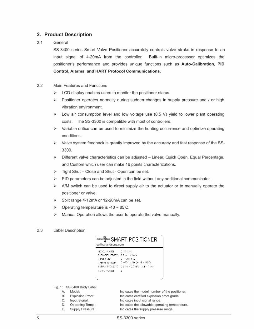
2.3 Label Description
Fig. 1: SS-3400 Body Label
A. Model: Indicates the model number of the positioner. B. Explosion Proof: Indicates certified explosion proof grade. C. Input Signal: Indicates input signal range. D. Operating Temp.: Indicates the allowable operating temperature. E. Supply Pressure: Indicates the supply pressure range.
Sullivan & SonsProduct Manual: S&S V-100 Ball Valve
Sullivan & Sons Instrumentation Valves
20
P.O. Box 1706450 Covington RoadHaughton, LA 71037Phone 318.949.1591
Fax 318.949.9046
Website: www.sullivanandsons.com Email: [email protected]
sullivanandsons.com
SS-3300
6 SS-3300 series
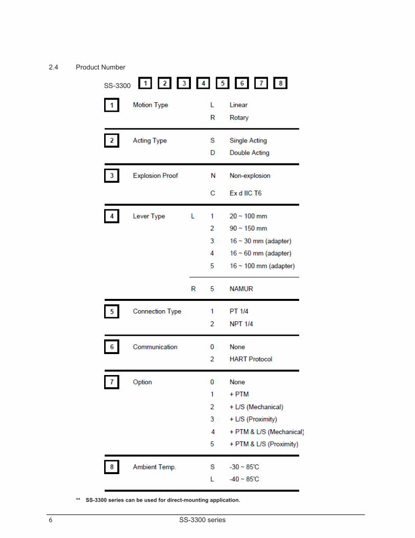
2.4 Product Number ** SS-3300 series can be used for direct-mounting application.
SS-3300
7 SS-3300 series
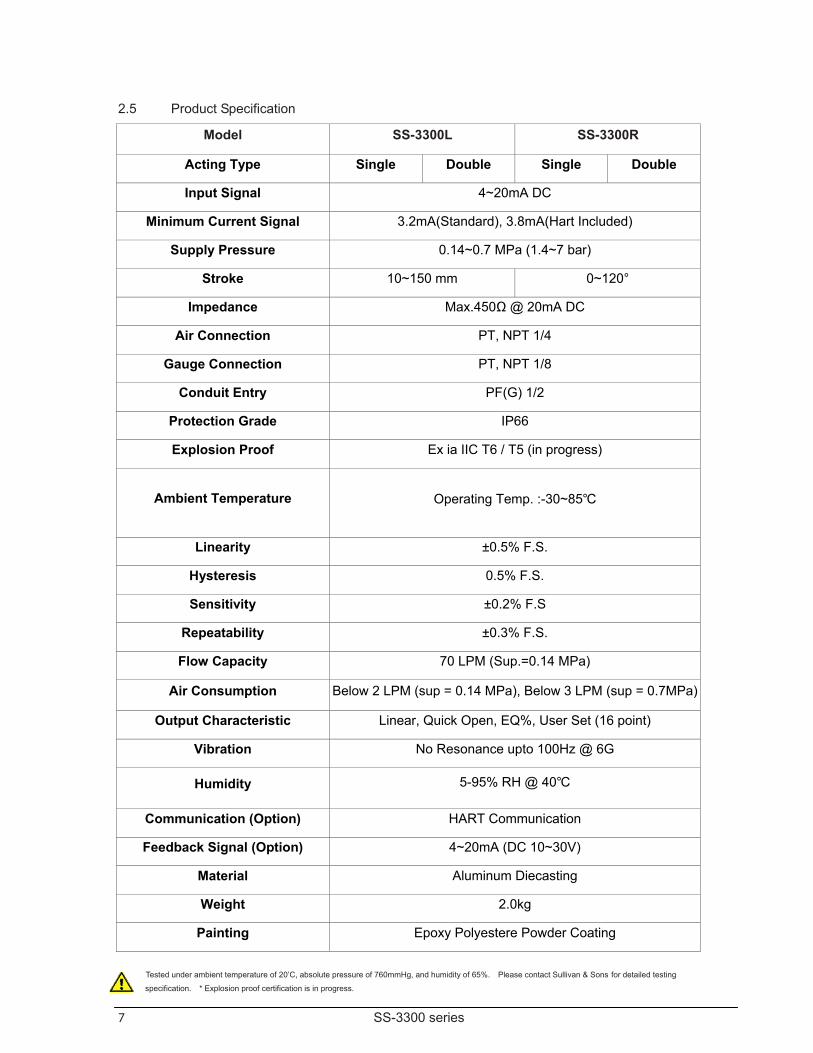
2.5 Product Specification Model SS-3300L SS-3300R
Tested under ambient temperature of 20’C, absolute pressure of 760mmHg, and humidity of 65%. Please contact Sullivan & Sons for detailed testing
specification. * Explosion proof certification is in progress.
Acting Type Single Double Single Double
Input Signal 4~20mA DC
Minimum Current Signal 3.2mA(Standard), 3.8mA(Hart Included)
Supply Pressure 0.14~0.7 MPa (1.4~7 bar)
Stroke 10~150 mm 0~120°
Impedance Max.450Ω @ 20mA DC
Air Connection PT, NPT 1/4
Gauge Connection PT, NPT 1/8
Conduit Entry PF(G) 1/2
Protection Grade IP66
Explosion Proof Ex ia IIC T6 / T5 (in progress)
Ambient Temperature Operating Temp. :-30~85
Linearity ±0.5% F.S.
Hysteresis 0.5% F.S.
Sensitivity ±0.2% F.S
Repeatability ±0.3% F.S.
Flow Capacity 70 LPM (Sup.=0.14 MPa)
Air Consumption Below 2 LPM (sup = 0.14 MPa), Below 3 LPM (sup = 0.7MPa)
Output Characteristic Linear, Quick Open, EQ%, User Set (16 point)
Vibration No Resonance upto 100Hz @ 6G
Humidity 5-95% RH @ 40
Communication (Option) HART Communication
Feedback Signal (Option) 4~20mA (DC 10~30V)
Material Aluminum Diecasting
Weight 2.0kg
Painting Epoxy Polyestere Powder Coating
8 SS-3300 series
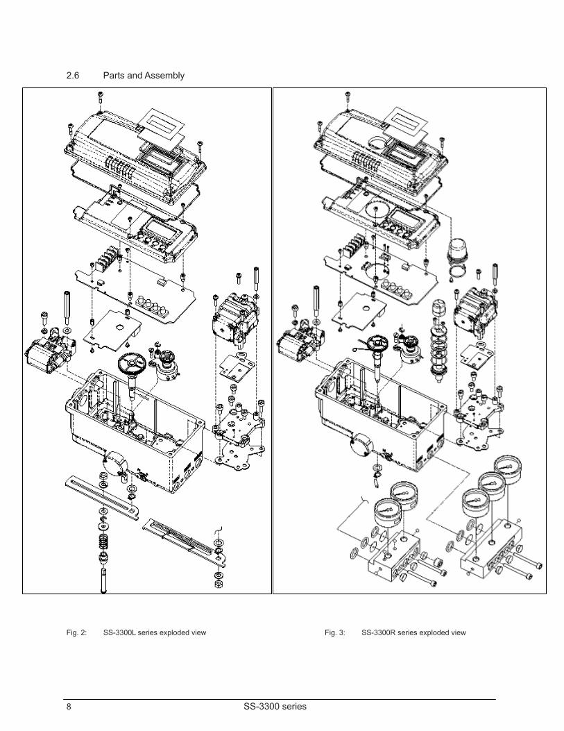
2.6 Parts and Assembly
Fig. 2: SS-3300L series exploded view Fig. 3: SS-3300R series exploded view
8 SS-3300 series
2.6 Parts and Assembly
Fig. 2: SS-3300L series exploded view Fig. 3: SS-3300R series exploded view
9 SS-3300 series
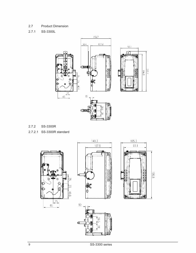
2.7 Product Dimension 2.7.1 SS-3300L
2.7.2 SS-3300R 2.7.2.1 SS-3300R standard
10 SS-3300 series
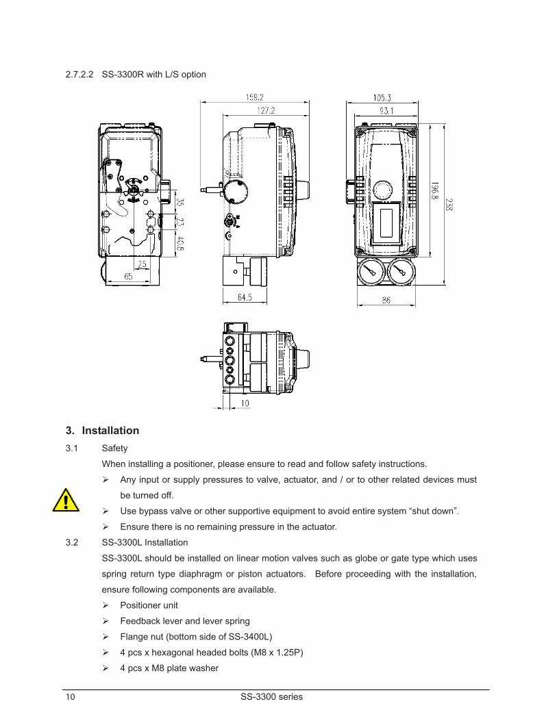
2.7.2.2 SS-3300R with L/S option
3. Installation 3.1 Safety
When installing a positioner, please ensure to read and follow safety instructions.
Any input or supply pressures to valve, actuator, and / or to other related devices must
be turned off. Use bypass valve or other supportive equipment to avoid entire system “shut down”. Ensure there is no remaining pressure in the actuator.
3.2 SS-3300L Installation SS-3300L should be installed on linear motion valves such as globe or gate type which uses
spring return type diaphragm or piston actuators. Before proceeding with the installation,
ensure following components are available.
Positioner unit Feedback lever and lever spring Flange nut (bottom side of SS-3400L) 4 pcs x hexagonal headed bolts (M8 x 1.25P) 4 pcs x M8 plate washer
11 SS-3300 series
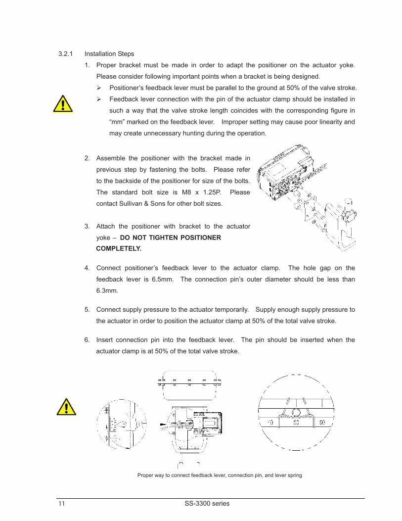
3.2.1 Installation Steps 1. Proper bracket must be made in order to adapt the positioner on the actuator yoke.
Please consider following important points when a bracket is being designed. Positioner’s feedback lever must be parallel to the ground at 50% of the valve stroke. Feedback lever connection with the pin of the actuator clamp should be installed in
such a way that the valve stroke length coincides with the corresponding figure in
“mm” marked on the feedback lever. Improper setting may cause poor linearity and
may create unnecessary hunting during the operation.
2. Assemble the positioner with the bracket made in
previous step by fastening the bolts. Please refer
to the backside of the positioner for size of the bolts.
The standard bolt size is M8 x 1.25P. Please
contact Sullivan & Sons for other bolt sizes.
3. Attach the positioner with bracket to the actuator
yoke – DO NOT TIGHTEN POSITIONER COMPLETELY.
4. Connect positioner’s feedback lever to the actuator clamp. The hole gap on the
feedback lever is 6.5mm. The connection pin’s outer diameter should be less than
6.3mm.
5. Connect supply pressure to the actuator temporarily. Supply enough supply pressure to
the actuator in order to position the actuator clamp at 50% of the total valve stroke.
6. Insert connection pin into the feedback lever. The pin should be inserted when the
actuator clamp is at 50% of the total valve stroke.
Proper way to connect feedback lever, connection pin, and lever spring
12 SS-3300 series
7. Check if feedback lever is parallel to the ground at 50% of the valve stroke. If it is not
parallel, adjust the bracket or feedback link bar to make parallel. Improper installation
may cause poor linearity and may create unnecessary hunting during the operation.
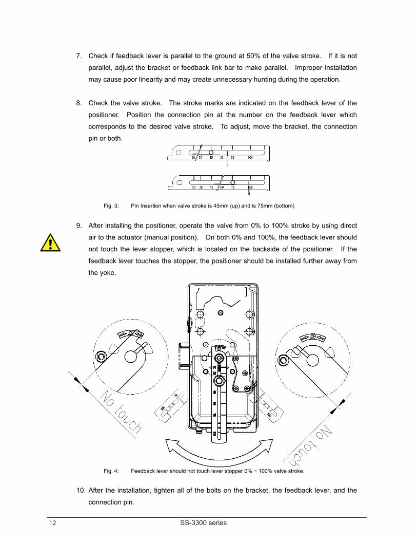
8. Check the valve stroke. The stroke marks are indicated on the feedback lever of the
positioner. Position the connection pin at the number on the feedback lever which
corresponds to the desired valve stroke. To adjust, move the bracket, the connection
pin or both.
Fig. 3: Pin Insertion when valve stroke is 45mm (up) and is 75mm (bottom)
9. After installing the positioner, operate the valve from 0% to 100% stroke by using direct
air to the actuator (manual position). On both 0% and 100%, the feedback lever should
not touch the lever stopper, which is located on the backside of the positioner. If the
feedback lever touches the stopper, the positioner should be installed further away from
the yoke.
Fig. 4: Feedback lever should not touch lever stopper 0% ~ 100% valve stroke.
10. After the installation, tighten all of the bolts on the bracket, the feedback lever, and the
connection pin.
13 SS-3300 series
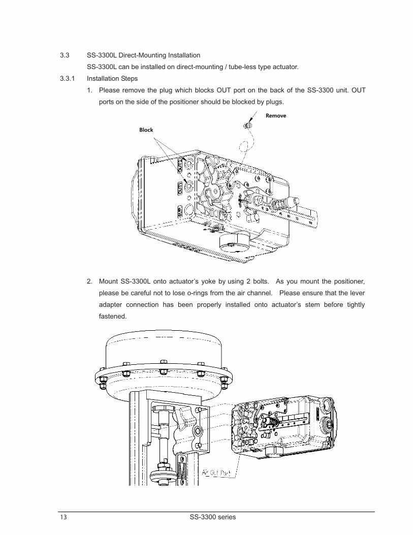
3.3 SS-3300L Direct-Mounting Installation SS-3300L can be installed on direct-mounting / tube-less type actuator.
3.3.1 Installation Steps 1. Please remove the plug which blocks OUT port on the back of the SS-3300 unit. OUT
ports on the side of the positioner should be blocked by plugs.
2. Mount SS-3300L onto actuator’s yoke by using 2 bolts. As you mount the positioner,
please be careful not to lose o-rings from the air channel. Please ensure that the lever
adapter connection has been properly installed onto actuator’s stem before tightly
fastened.
Remove
Block
14 SS-3300 series
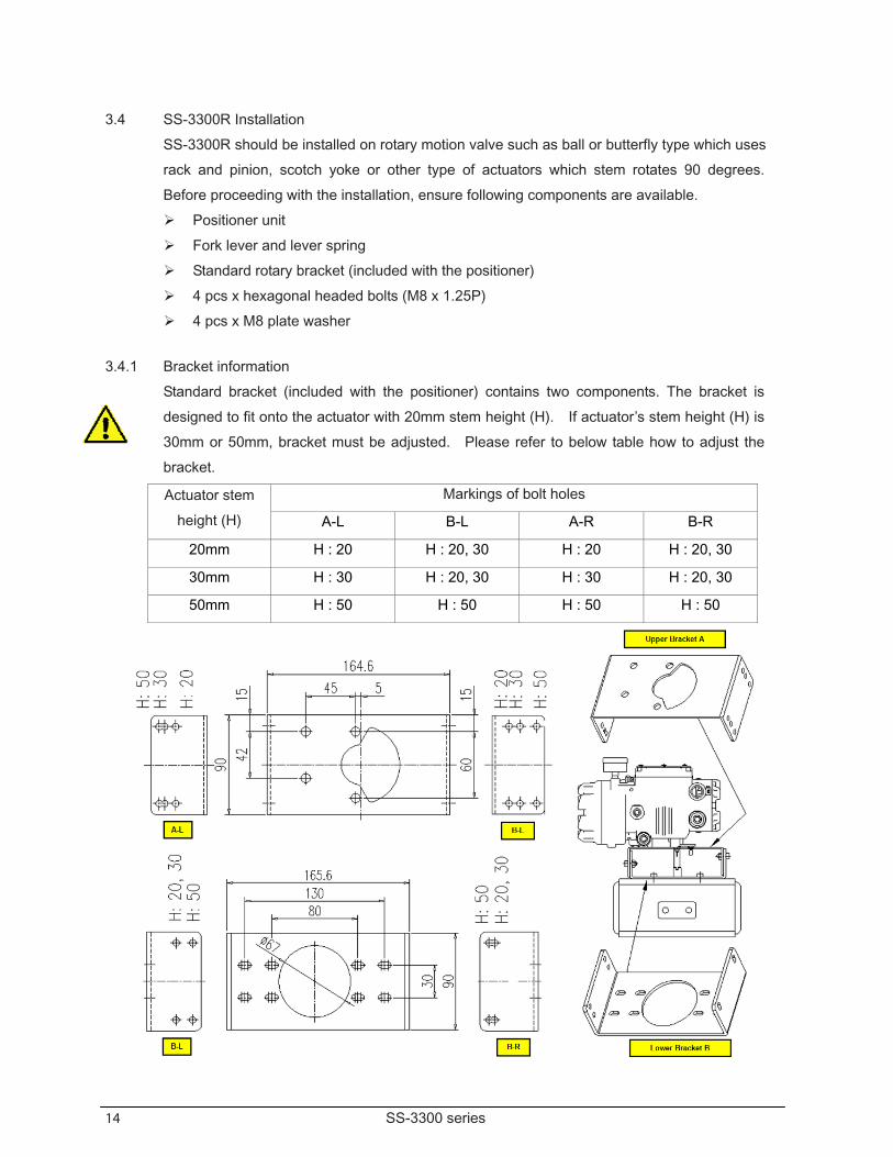
3.4 SS-3300R Installation SS-3300R should be installed on rotary motion valve such as ball or butterfly type which uses
rack and pinion, scotch yoke or other type of actuators which stem rotates 90 degrees.
Before proceeding with the installation, ensure following components are available.
Positioner unit Fork lever and lever spring Standard rotary bracket (included with the positioner) 4 pcs x hexagonal headed bolts (M8 x 1.25P) 4 pcs x M8 plate washer
3.4.1 Bracket information Standard bracket (included with the positioner) contains two components. The bracket is
designed to fit onto the actuator with 20mm stem height (H). If actuator’s stem height (H) is
30mm or 50mm, bracket must be adjusted. Please refer to below table how to adjust the
bracket.
Actuator stem
height (H)
Markings of bolt holes
A-L B-L A-R B-R
20mm H : 20 H : 20, 30 H : 20 H : 20, 30
30mm H : 30 H : 20, 30 H : 30 H : 20, 30
50mm H : 50 H : 50 H : 50 H : 50
15 SS-3300 series
4. Connections
4.1 Safety Supply pressure should be clean and dry air – avoiding moisture, oil or dust. Always recommended to use air filter regulator (i.e. SS-200 series). Sullivan & Sons has not tested positioner’s operation with any other gases
other than clean air. Please contact Sullivan & Sons for any questions.
4.2 Supply Pressure Condition
Dry air with at least 10˚C lower than ambient temperature.
Avoid from dusty air. Positioner’s inner filter can only filter 5 micron or larger. Avoid oil. Comply with ANSI/ISA-57.3 1975(R1981) or ISA S7.3-1975(R1981). Supply pressure range is 1.4 ~ 7 kgf/cm2 (140-700 kPA) Set air filter regulator’s pressure level 10% higher than actuator’s spring range pressure.
4.3 Piping Condition Ensure inside of pipe is clean of obstructions. Do not use pipeline that is squeezed or shows any type of damages. Pipeline should have more than 6mm of inner diameter (10mm outer diameter) to
maintain flow rate. The length of pipeline system should not be extremely long. Longer pipeline system
may affect flow rate due to the friction inside of the pipeline.
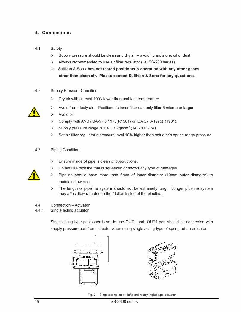
4.4 Connection – Actuator 4.4.1 Single acting actuator
Singe acting type positioner is set to use OUT1 port. OUT1 port should be connected with
supply pressure port from actuator when using single acting type of spring return actuator.
Fig. 7: Singe acting linear (left) and rotary (right) type actuator
16 SS-3300 series
4.4.2 Double acting actuator Double acting type positioner is set to use OUT1 and OUT2 port. As input signal increases,
the supply pressure will be supplied through OUT1 port.
Fig. 8: Double acting linear (left) and rotary (right) type actuator
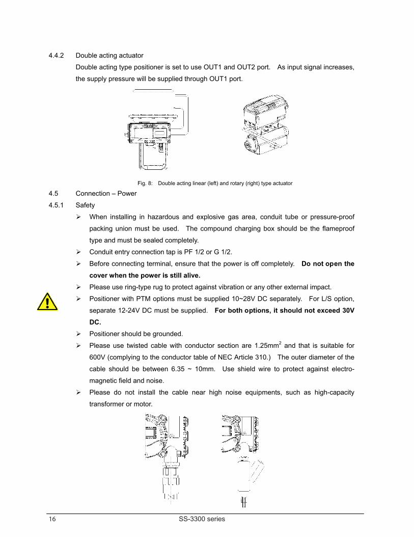
4.5 Connection – Power 4.5.1 Safety
When installing in hazardous and explosive gas area, conduit tube or pressure-proof
packing union must be used. The compound charging box should be the flameproof
type and must be sealed completely. Conduit entry connection tap is PF 1/2 or G 1/2. Before connecting terminal, ensure that the power is off completely. Do not open the
cover when the power is still alive. Please use ring-type rug to protect against vibration or any other external impact. Positioner with PTM options must be supplied 10~28V DC separately. For L/S option,
separate 12-24V DC must be supplied. For both options, it should not exceed 30V DC.
Positioner should be grounded. Please use twisted cable with conductor section are 1.25mm2 and that is suitable for
600V (complying to the conductor table of NEC Article 310.) The outer diameter of the
cable should be between 6.35 ~ 10mm. Use shield wire to protect against electro-
magnetic field and noise. Please do not install the cable near high noise equipments, such as high-capacity
transformer or motor.
17 SS-3300 series
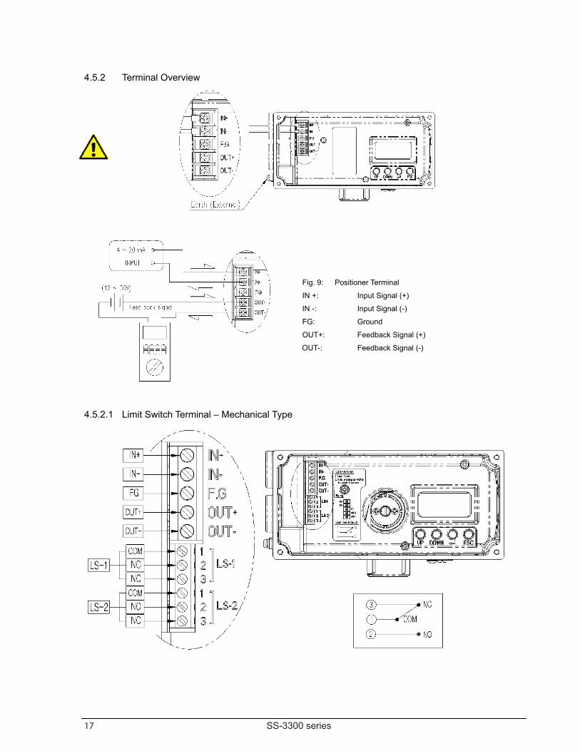
4.5.2 Terminal Overview
Fig. 9: Positioner Terminal
IN +: Input Signal (+)
IN -: Input Signal (-)
FG: Ground
OUT+: Feedback Signal (+)
OUT-: Feedback Signal (-)
4.5.2.1 Limit Switch Terminal – Mechanical Type
18 SS-3300 series
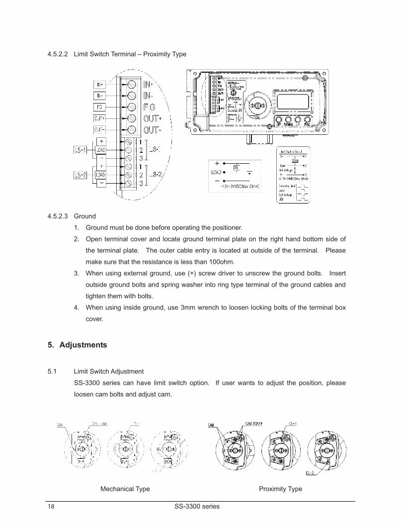
4.5.2.2 Limit Switch Terminal – Proximity Type
4.5.2.3 Ground 1. Ground must be done before operating the positioner. 2. Open terminal cover and locate ground terminal plate on the right hand bottom side of
the terminal plate. The outer cable entry is located at outside of the terminal. Please
make sure that the resistance is less than 100ohm. 3. When using external ground, use (+) screw driver to unscrew the ground bolts. Insert
outside ground bolts and spring washer into ring type terminal of the ground cables and
tighten them with bolts. 4. When using inside ground, use 3mm wrench to loosen locking bolts of the terminal box
cover.
5. Adjustments
5.1 Limit Switch Adjustment SS-3300 series can have limit switch option. If user wants to adjust the position, please
loosen cam bolts and adjust cam.
Mechanical Type Proximity Type
19 SS-3300 series
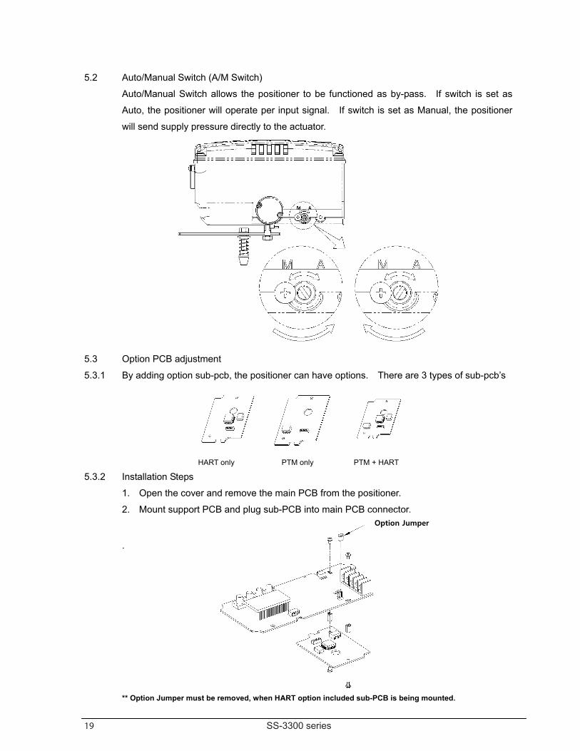
5.2 Auto/Manual Switch (A/M Switch) Auto/Manual Switch allows the positioner to be functioned as by-pass. If switch is set as
Auto, the positioner will operate per input signal. If switch is set as Manual, the positioner
will send supply pressure directly to the actuator.
5.3 Option PCB adjustment 5.3.1 By adding option sub-pcb, the positioner can have options. There are 3 types of sub-pcb’s
HART only PTM only PTM + HART
5.3.2 Installation Steps 1. Open the cover and remove the main PCB from the positioner. 2. Mount support PCB and plug sub-PCB into main PCB connector.
.
** Option Jumper must be removed, when HART option included sub-PCB is being mounted.
Option Jumper
20 SS-3300 series
6. Operation
6.1 Safety Following process will operate valve and ac tuator. Before proceed with any AUTO Calibration, please s eparate valve from the entire system, so AUTO Calibration will affect entire valve process.
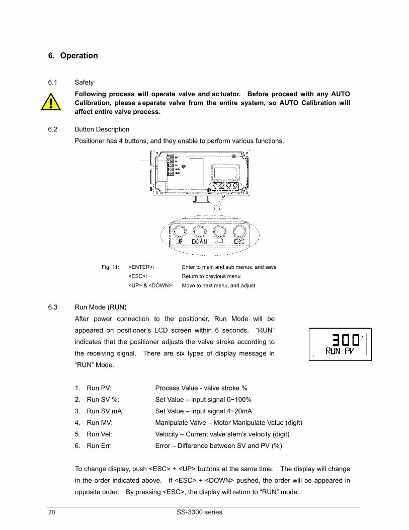
6.2 Button Description Positioner has 4 buttons, and they enable to perform various functions.
Fig. 11: <ENTER>: Enter to main and sub menus, and save
<ESC>: Return to previous menu
<UP> & <DOWN>: Move to next menu, and adjust.
6.3 Run Mode (RUN)
After power connection to the positioner, Run Mode will be
appeared on positioner’s LCD screen within 6 seconds. “RUN”
indicates that the positioner adjusts the valve stroke according to
the receiving signal. There are six types of display message in
“RUN” Mode.
1. Run PV: Process Value - valve stroke % 2. Run SV %: Set Value – input signal 0~100% 3. Run SV mA: Set Value – input signal 4~20mA 4. Run MV: Manipulate Valve – Motor Manipulate Value (digit) 5. Run Vel: Velocity – Current valve stem’s velocity (digit) 6. Run Err: Error – Difference between SV and PV (%) To change display, push <ESC> + <UP> buttons at the same time. The display will change
in the order indicated above. If <ESC> + <DOWN> pushed, the order will be appeared in
opposite order. By pressing <ESC>, the display will return to “RUN” mode.
21 SS-3300 series
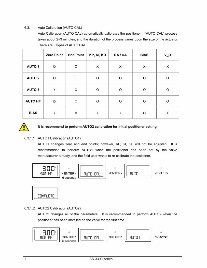
6.3.1 Auto Calibration (AUTO CAL) Auto Calibration (AUTO CAL) automatically calibrates the positioner. “AUTO CAL” process
takes about 2~3 minutes, and the duration of the process varies upon the size of the actuator.
There are 3 types of AUTO CAL.
Zero Point End Point KP, KI, KD RA / DA BIAS V_D
AUTO 1 O O X X X X
AUTO 2 O O O O O O
AUTO 3 X X O O O O
AUTO HF O O O O O O
BIAS X X X X O X
It is recommend to perform AUTO2 calibration for initial positioner setting.
6.3.1.1 AUTO1 Calibration (AUTO1) AUTO1 changes zero and end points; however, KP, KI, KD will not be adjusted. It is
recommended to perform AUTO1 when the positioner has been set by the valve
manufacturer already, and the field user wants to re-calibrate the positioner.
6.3.1.2 AUTO2 Calibration (AUTO2) AUTO2 changes all of the parameters. It is recommended to perform AUTO2 when the
positioner has been installed on the valve for the first time.
<ENTER> 6 seconds
<ENTER>
<ENTER>
<ENTER> 6 seconds
<ENTER>
<DOWN>
22 SS-3300 series
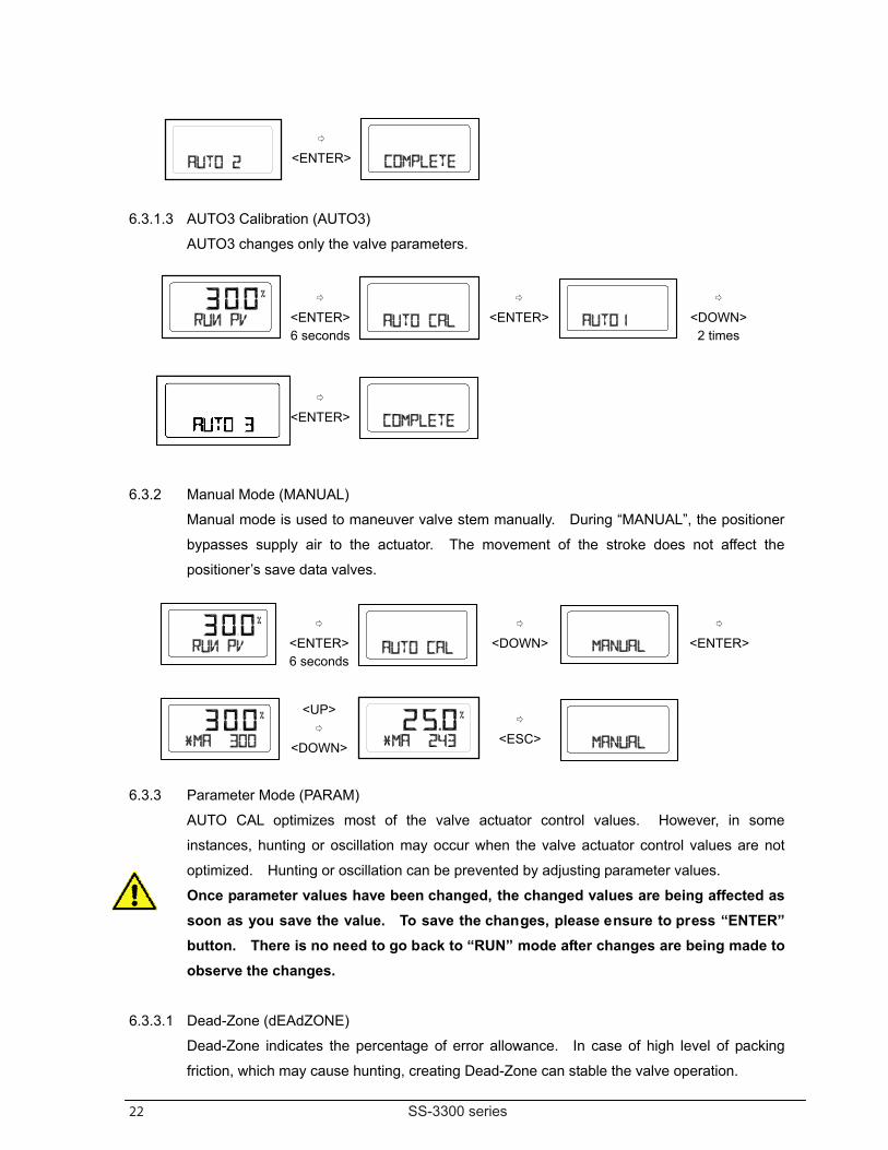
6.3.1.3 AUTO3 Calibration (AUTO3) AUTO3 changes only the valve parameters.
6.3.2 Manual Mode (MANUAL) Manual mode is used to maneuver valve stem manually. During “MANUAL”, the positioner
bypasses supply air to the actuator. The movement of the stroke does not affect the
positioner’s save data valves.
6.3.3 Parameter Mode (PARAM) AUTO CAL optimizes most of the valve actuator control values. However, in some
instances, hunting or oscillation may occur when the valve actuator control values are not
optimized. Hunting or oscillation can be prevented by adjusting parameter values.
Once parameter values have been changed, the changed values are being affected as soon as you save the value. To save the changes, please ensure to press “ENTER” button. There is no need to go back to “RUN” mode after changes are being made to observe the changes.
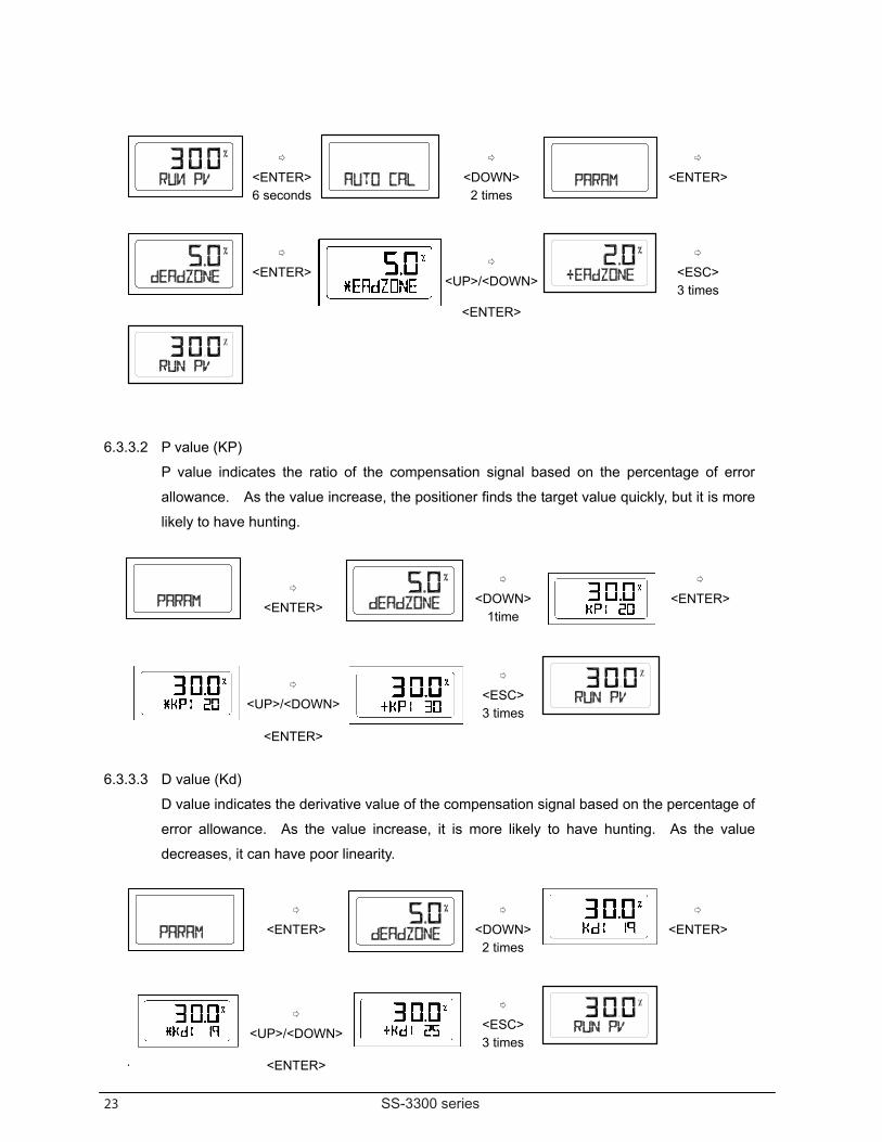
6.3.3.1 Dead-Zone (dEAdZONE) Dead-Zone indicates the percentage of error allowance. In case of high level of packing
friction, which may cause hunting, creating Dead-Zone can stable the valve operation.
<ENTER>
<ENTER> 6 seconds
<ENTER>
<DOWN>2 times
<ENTER>
<ENTER> 6 seconds
<DOWN>
<ENTER>
<UP>
<DOWN>
<ESC>
23 SS-3300 series
6.3.3.2 P value (KP) P value indicates the ratio of the compensation signal based on the percentage of error
allowance. As the value increase, the positioner finds the target value quickly, but it is more
likely to have hunting.
6.3.3.3 D value (Kd) D value indicates the derivative value of the compensation signal based on the percentage of
error allowance. As the value increase, it is more likely to have hunting. As the value
decreases, it can have poor linearity.
<ENTER> 6 seconds
<DOWN> 2 times
<ENTER>
<ENTER>
<UP>/<DOWN>
<ESC> 3 times
<ENTER>
<ENTER>
<DOWN>1time
<ENTER>
<UP>/<DOWN>
<ESC> 3 times
<ENTER>
<ENTER>
<DOWN>2 times
<ENTER>
<UP>/<DOWN>
<ESC> 3 times
· <ENTER>
24 SS-3300 series
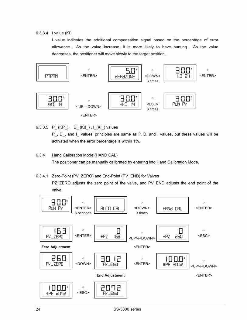
6.3.3.4 I value (KI) I value indicates the additional compensation signal based on the percentage of error
allowance. As the value increase, it is more likely to have hunting. As the value
decreases, the positioner will move slowly to the target position.
6.3.3.5 P_ (KP_), D_ (Kd_) , I_(KI_) values
P_, D_, and I_ values’ principles are same as P, D, and I values, but these values will be
activated when the error percentage is within 1%.
6.3.4 Hand Calibration Mode (HAND CAL)
The positioner can be manually calibrated by entering into Hand Calibration Mode.
6.3.4.1 Zero-Point (PV_ZERO) and End-Point (PV_END) for Valves
PZ_ZERO adjusts the zero point of the valve, and PV_END adjusts the end point of the
valve.
<ENTER>
<DOWN>3 times
<ENTER>
<UP><DOWN>
<ESC> 3 times
<ENTER>
<ENTER> 6 seconds
<DOWN> 3 times
<ENTER>
<ENTER>
<UP>/<DOWN>
<ESC>
Zero Adjustment <ENTER>
<DOWN>
<ENTER>
<UP>/<DOWN>
End Adjustment <ENTER>
<ESC>
25 SS-3300 series
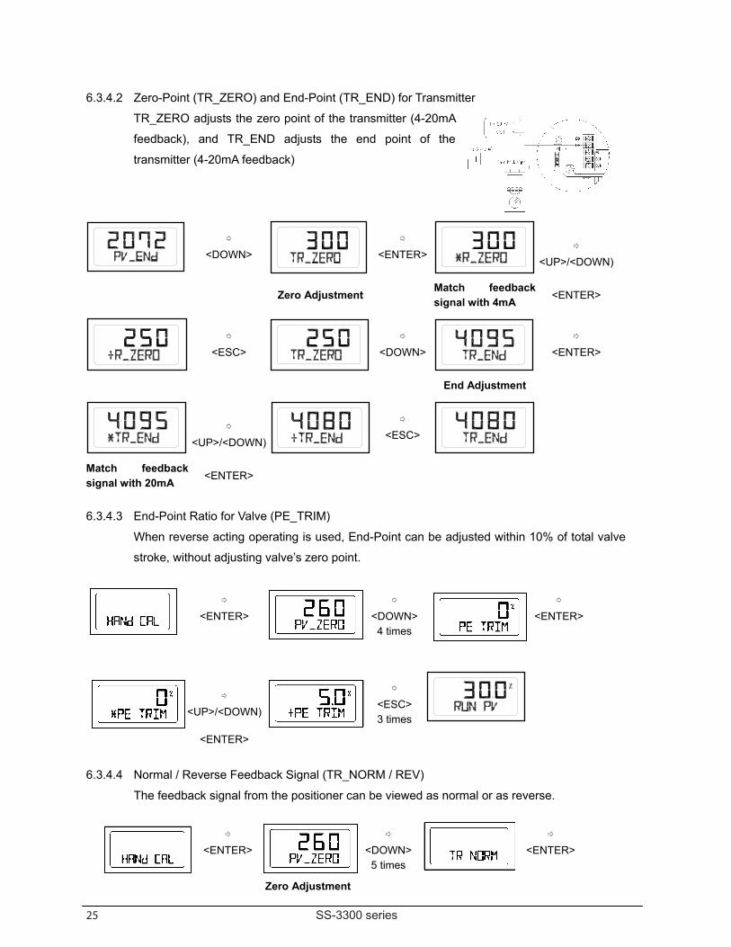
6.3.4.2 Zero-Point (TR_ZERO) and End-Point (TR_END) for Transmitter TR_ZERO adjusts the zero point of the transmitter (4-20mA
feedback), and TR_END adjusts the end point of the
transmitter (4-20mA feedback)
6.3.4.3 End-Point Ratio for Valve (PE_TRIM)
When reverse acting operating is used, End-Point can be adjusted within 10% of total valve
stroke, without adjusting valve’s zero point.
6.3.4.4 Normal / Reverse Feedback Signal (TR_NORM / REV)
The feedback signal from the positioner can be viewed as normal or as reverse.
<DOWN>
<ENTER>
<UP>/<DOWN)
Zero Adjustment
Match feedback signal with 4mA
<ENTER>
<ESC>
<DOWN>
<ENTER>
End Adjustment
<UP>/<DOWN)
<ESC>
Match feedback signal with 20mA
<ENTER>
<ENTER>
<DOWN>4 times
<ENTER>
<UP>/<DOWN)
<ESC> 3 times
<ENTER>
<ENTER>
<DOWN>5 times
<ENTER>
Zero Adjustment
26 SS-3300 series
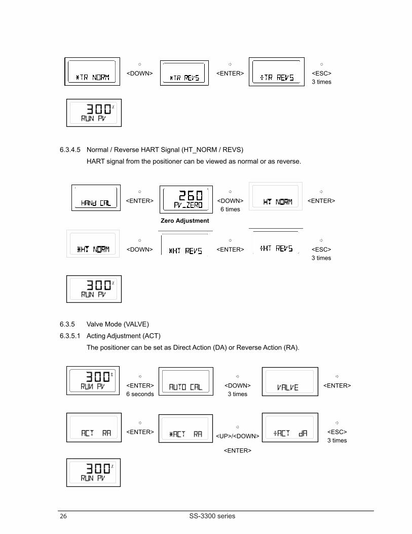
6.3.4.5 Normal / Reverse HART Signal (HT_NORM / REVS)
HART signal from the positioner can be viewed as normal or as reverse.
6.3.5 Valve Mode (VALVE) 6.3.5.1 Acting Adjustment (ACT)
The positioner can be set as Direct Action (DA) or Reverse Action (RA).
<DOWN>
<ENTER>
<ESC> 3 times
<ENTER>
<DOWN>6 times
<ENTER>
Zero Adjustment
<DOWN>
<ENTER>
<ESC> 3 times
<ENTER> 6 seconds
<DOWN> 3 times
<ENTER>
<ENTER>
<UP>/<DOWN>
<ESC> 3 times
<ENTER>
27 SS-3300 series
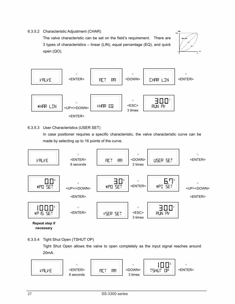
6.3.5.2 Characteristic Adjustment (CHAR) The valve characteristic can be set on the field’s requirement. There are
3 types of characteristics – linear (LIN), equal percentage (EQ), and quick
open (QO).
6.3.5.3 User Characteristics (USER SET) In case positioner requires a specific characteristic, the valve characteristic curve can be
made by selecting up to 16 points of the curve.
6.3.5.4 Tight Shut Open (TSHUT OP) Tight Shut Open allows the valve to open completely as the input signal reaches around
20mA.
<ENTER>
<DOWN>
<ENTER>
<UP>/<DOWN>
<ESC> 3 times
<ENTER>
<ENTER> 6 seconds
<DOWN>2 times
<ENTER>
<UP>/<DOWN>
<ENTER>
<UP><DOWN>
<ENTER> <ENTER>
<ENTER>
<ESC>3 times
Repeat step if necessary
<ENTER> 6 seconds
<DOWN> 3 times
<ENTER>
28 SS-3300 series
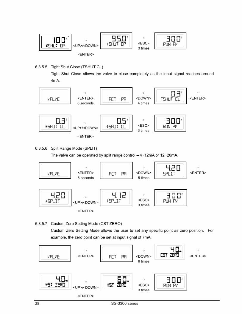
6.3.5.5 Tight Shut Close (TSHUT CL) Tight Shut Close allows the valve to close completely as the input signal reaches around
4mA.
6.3.5.6 Split Range Mode (SPLIT) The valve can be operated by split range control – 4~12mA or 12~20mA.
6.3.5.7 Custom Zero Setting Mode (CST ZERO) Custom Zero Setting Mode allows the user to set any specific point as zero position. For
example, the zero point can be set at input signal of 7mA.
<UP>/<DOWN>
<ESC> 3 times
<ENTER>
<ENTER> 6 seconds
<DOWN>4 times
<ENTER>
<UP>/<DOWN>
<ESC> 3 times
<ENTER>
<ENTER> 6 seconds
<DOWN>5 times
<ENTER>
<UP>/<DOWN>
<ESC> 3 times
<ENTER>
<ENTER>
<DOWN>6 times
<ENTER>
<UP>/<DOWN>
<ESC> 3 times
<ENTER>
29 SS-3300 series
SS-3300L Positioner model
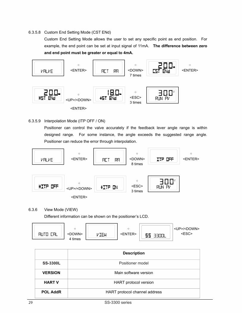
6.3.5.8 Custom End Setting Mode (CST ENd) Custom End Setting Mode allows the user to set any specific point as end position. For
example, the end point can be set at input signal of 11mA. The difference between zero and end point must be greater or equal to 4mA.
6.3.5.9 Interpolation Mode (ITP OFF / ON)
Positioner can control the valve accurately if the feedback lever angle range is within
designed range. For some instance, the angle exceeds the suggested range angle.
Positioner can reduce the error through interpolation.
6.3.6 View Mode (VIEW) Different information can be shown on the positioner’s LCD.
Description
VERSION Main software version
HART V HART protocol version
POL AddR HART protocol channel address
<ENTER>
<DOWN>7 times
<ENTER>
<UP>/<DOWN>
<ESC> 3 times
<ENTER>
<ENTER>
<DOWN>8 times
<ENTER>
<UP>/<DOWN>
<ESC> 3 times
<ENTER>
<DOWN> 4 times
<ENTER>
<UP>/<DOWN><ESC>
29 SS-3300 series
SS-3300L Positioner model
6.3.5.8 Custom End Setting Mode (CST ENd) Custom End Setting Mode allows the user to set any specific point as end position. For
example, the end point can be set at input signal of 11mA. The difference between zero and end point must be greater or equal to 4mA.
6.3.5.9 Interpolation Mode (ITP OFF / ON)
Positioner can control the valve accurately if the feedback lever angle range is within
designed range. For some instance, the angle exceeds the suggested range angle.
Positioner can reduce the error through interpolation.
6.3.6 View Mode (VIEW) Different information can be shown on the positioner’s LCD.
Description
VERSION Main software version
HART V HART protocol version
POL AddR HART protocol channel address
<ENTER>
<DOWN>7 times
<ENTER>
<UP>/<DOWN>
<ESC> 3 times
<ENTER>
<ENTER>
<DOWN>8 times
<ENTER>
<UP>/<DOWN>
<ESC> 3 times
<ENTER>
<DOWN> 4 times
<ENTER>
<UP>/<DOWN><ESC>
30 SS-3300 series
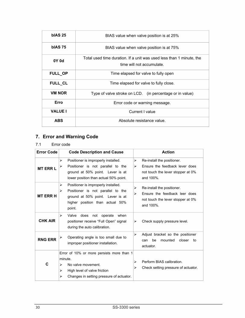
bIAS 25 BIAS value when valve position is at 25%
bIAS 75 BIAS value when valve position is at 75%
0Y 0d Total used time duration. If a unit was used less than 1 minute, the
time will not accumulate.
FULL_OP Time elapsed for valve to fully open
FULL_CL Time elapsed for valve to fully close.
VM NOR Type of valve stroke on LCD. (in percentage or in value)
Erro Error code or warning message.
VALUE I Current I value
ABS Absolute resistance value.
7. Error and Warning Code 7.1 Error code Error Code Code Description and Cause Action
MT ERR L
Positioner is improperly installed. Positioner is not parallel to the
ground at 50% point. Lever is at lower position than actual 50% point.
Re-install the positioner. Ensure the feedback lever does
not touch the lever stopper at 0% and 100%.
MT ERR H
Positioner is improperly installed. Positioner is not parallel to the
ground at 50% point. Lever is at higher position than actual 50% point.
Re-install the positioner. Ensure the feedback leer does
not touch the lever stopper at 0% and 100%.
CHK AIR Valve does not operate when
positioner receive “Full Open” signal during the auto calibration.
Check supply pressure level.
RNG ERR Operating angle is too small due to improper positioner installation.
Adjust bracket so the positioner can be mounted closer to actuator.
C
Error of 10% or more persists more than 1 minute. No valve movement. High level of valve friction Changes in setting pressure of actuator.
Perform BIAS calibration. Check setting pressure of actuator.
31 SS-3300 series
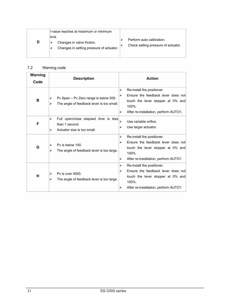
D
I-value reaches at maximum or minimum limit. Changes in valve friction. Changes in setting pressure of actuator.
Perform auto calibration. Check setting pressure of actuator.
7.2 Warning code
Warning
Code Description Action
B Pv Span – Pv Zero range is below 500. The angle of feedback lever is too small.
Re-install the positioner. Ensure the feedback lever does not
touch the lever stopper at 0% and 100%.
After re-installation, perform AUTO1.
F Full open/close elapsed time is less
than 1 second. Actuator size is too small.
Use variable orifice. Use larger actuator.
G Pv is below 100. The angle of feedback lever is too large.
Re-install the positioner. Ensure the feedback lever does not
touch the lever stopper at 0% and 100%.
After re-installation, perform AUTO1
H Pv is over 4000. The angle of feedback lever is too large.
Re-install the positioner. Ensure the feedback lever does not
touch the lever stopper at 0% and 100%.
After re-installation, perform AUTO1
32 SS-3300 series
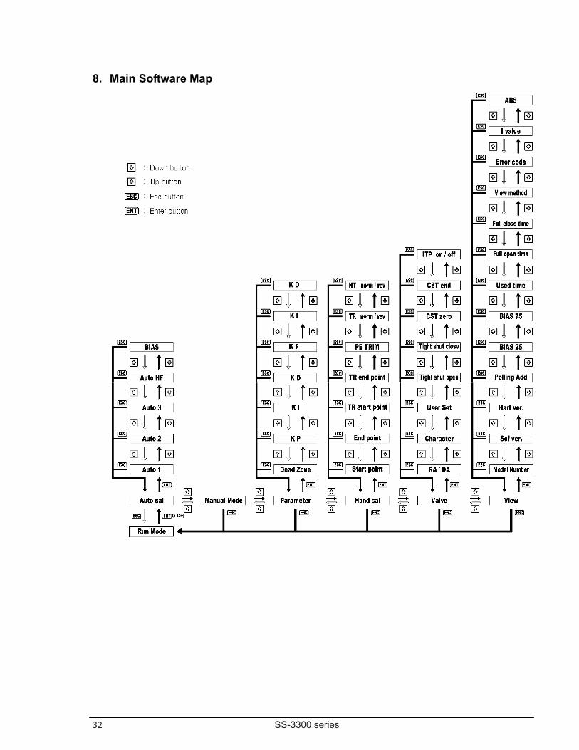
8. Main Software Map
33 SS-3300 series
Sullivan & SonsProduct Manual: S&S V-100 Ball Valve
Sullivan & Sons Instrumentation Valves
20
P.O. Box 1706450 Covington RoadHaughton, LA 71037Phone 318.949.1591
Fax 318.949.9046
Website: www.sullivanandsons.com Email: [email protected]