Embed Size (px)
Citation preview
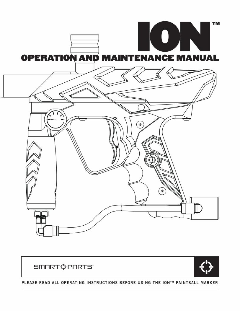
PLEASE READ ALL OPERATING INSTRUCTIONS BEFORE USING THE ION™ PAINTBALL MARKER
IONOPERATION AND MAINTENANCE MANUAL
™
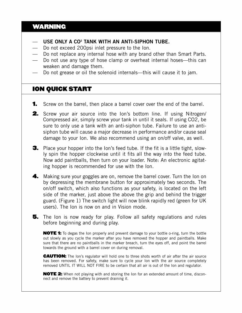
ION QUICK START
WARNING
1. Screw on the barrel, then place a barrel cover over the end of the barrel.
2. Screw your air source into the Ion’s bottom line. If using Nitrogen/Compressed air, simply screw your tank in until it seals. If using CO2, besure to only use a tank with an anti-siphon tube. Failure to use an anti-siphon tube will cause a major decrease in performance and/or cause sealdamage to your Ion. We also recommend using an on/off valve, as well.
3. Place your hopper into the Ion’s feed tube. If the fit is a little tight, slow-ly spin the hopper clockwise until it fits all the way into the feed tube.Now add paintballs, then turn on your loader. Note: An electronic agitat-ing hopper is recommended for use with the Ion.
4. Making sure your goggles are on, remove the barrel cover. Turn the Ion onby depressing the membrane button for approximately two seconds. Theon/off switch, which also functions as your safety, is located on the leftside of the marker, just above the above the grip and behind the triggerguard. (Figure 1) The switch light will now blink rapidly red (green for UKusers). The Ion is now on and in Vision mode.
5. The Ion is now ready for play. Follow all safety regulations and rulesbefore beginning and during play.
NOTE 1: To degas the Ion properly and prevent damage to your bottle o-ring, turn the bottleout slowly as you cycle the marker after you have removed the hopper and paintballs. Makesure that there are no paintballs in the marker breach, turn the eyes off, and point the barreltowards the ground with a barrel cover on during removal.
CAUTION: The Ion’s regulator will hold one to three shots worth of air after the air sourcehas been removed. For safety, make sure to cycle your Ion with the air source completelyremoved UNTIL IT WILL NOT FIRE to be certain that all air is out of the Ion and regulator.
NOTE 2: When not playing with and storing the Ion for an extended amount of time, discon-nect and remove the battery to prevent draining it.
— USE ONLY A CO2 TANK WITH AN ANTI-SIPHON TUBE.— Do not exceed 200psi inlet pressure to the Ion.— Do not replace any internal hose with any brand other than Smart Parts.— Do not use any type of hose clamp or overheat internal hoses—this can
weaken and damage them.— Do not grease or oil the solenoid internals—this will cause it to jam.
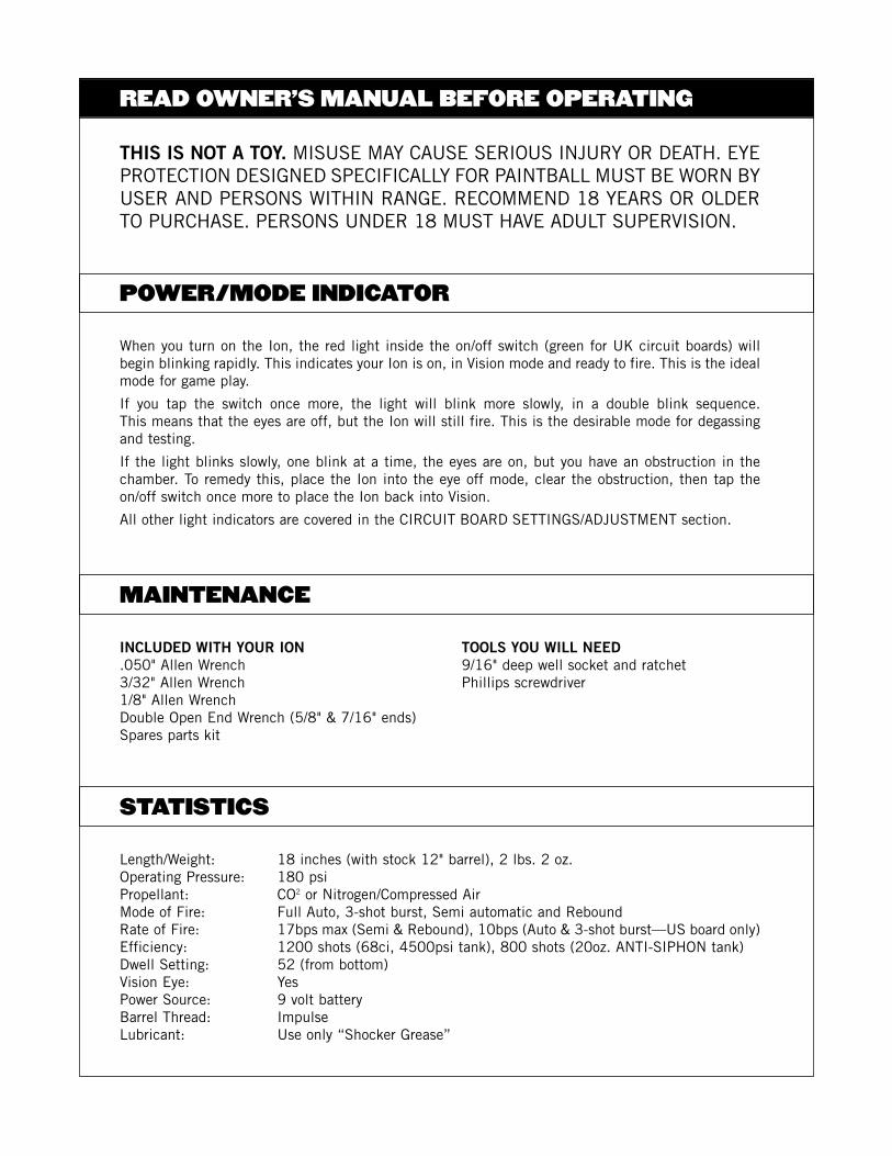
When you turn on the Ion, the red light inside the on/off switch (green for UK circuit boards) willbegin blinking rapidly. This indicates your Ion is on, in Vision mode and ready to fire. This is the idealmode for game play.
If you tap the switch once more, the light will blink more slowly, in a double blink sequence. This means that the eyes are off, but the Ion will still fire. This is the desirable mode for degassingand testing.
If the light blinks slowly, one blink at a time, the eyes are on, but you have an obstruction in thechamber. To remedy this, place the Ion into the eye off mode, clear the obstruction, then tap theon/off switch once more to place the Ion back into Vision.
All other light indicators are covered in the CIRCUIT BOARD SETTINGS/ADJUSTMENT section.
POWER/MODE INDICATOR
INCLUDED WITH YOUR ION TOOLS YOU WILL NEED.050" Allen Wrench 9/16" deep well socket and ratchet3/32" Allen Wrench Phillips screwdriver1/8" Allen WrenchDouble Open End Wrench (5/8" & 7/16" ends)Spares parts kit
MAINTENANCE
THIS IS NOT A TOY. MISUSE MAY CAUSE SERIOUS INJURY OR DEATH. EYEPROTECTION DESIGNED SPECIFICALLY FOR PAINTBALL MUST BE WORN BYUSER AND PERSONS WITHIN RANGE. RECOMMEND 18 YEARS OR OLDERTO PURCHASE. PERSONS UNDER 18 MUST HAVE ADULT SUPERVISION.
Length/Weight: 18 inches (with stock 12" barrel), 2 lbs. 2 oz.Operating Pressure: 180 psiPropellant: CO2 or Nitrogen/Compressed AirMode of Fire: Full Auto, 3-shot burst, Semi automatic and ReboundRate of Fire: 17bps max (Semi & Rebound), 10bps (Auto & 3-shot burst—US board only)Efficiency: 1200 shots (68ci, 4500psi tank), 800 shots (20oz. ANTI-SIPHON tank)Dwell Setting: 52 (from bottom)Vision Eye: YesPower Source: 9 volt batteryBarrel Thread: ImpulseLubricant: Use only “Shocker Grease”
READ OWNER’S MANUAL BEFORE OPERATING
STATISTICS

ION
AS
SE
MB
LYD
IAG
RA
M
1. Remove all paintballs and hopper, then remove all air sources to degas the Ion.
2. Remove barrel. Looking from above the marker, remove the vertical screw with your 1/8" Allenwrench and set aside.
3. Remove both left side grip screws (the side of the marker with the gauge on it), then open thegrip and disconnect the battery. NOTE: ONLY REMOVE THE BATTERY BY SEPARATING THECONNECTOR DIRECTLY FROM THE BATTERY. PULLING ON CIRCUIT BOARD WIRES CAN ANDWILL CAUSE SIGNIFICANT AND EXPENSIVE DAMAGE.
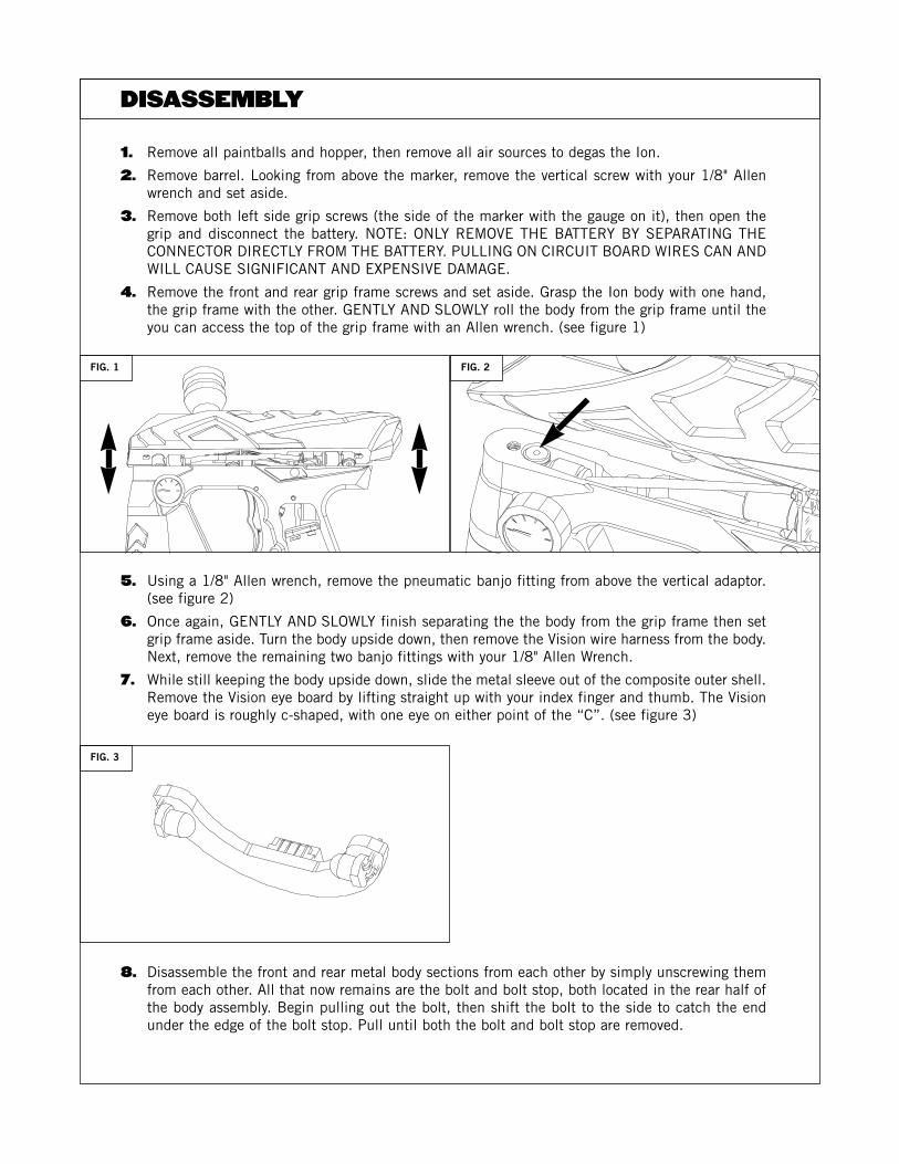
4. Remove the front and rear grip frame screws and set aside. Grasp the Ion body with one hand,the grip frame with the other. GENTLY AND SLOWLY roll the body from the grip frame until theyou can access the top of the grip frame with an Allen wrench. (see figure 1)
5. Using a 1/8" Allen wrench, remove the pneumatic banjo fitting from above the vertical adaptor.(see figure 2)
6. Once again, GENTLY AND SLOWLY finish separating the the body from the grip frame then setgrip frame aside. Turn the body upside down, then remove the Vision wire harness from the body.Next, remove the remaining two banjo fittings with your 1/8" Allen Wrench.
7. While still keeping the body upside down, slide the metal sleeve out of the composite outer shell.Remove the Vision eye board by lifting straight up with your index finger and thumb. The Visioneye board is roughly c-shaped, with one eye on either point of the “C”. (see figure 3)
8. Disassemble the front and rear metal body sections from each other by simply unscrewing themfrom each other. All that now remains are the bolt and bolt stop, both located in the rear half ofthe body assembly. Begin pulling out the bolt, then shift the bolt to the side to catch the endunder the edge of the bolt stop. Pull until both the bolt and bolt stop are removed.
DISASSEMBLY
FIG. 1
FIG. 3
FIG. 2
1. Cleaning the Ion is a simple process. Use a soft damp cloth to wipe down the parts, both inter-nal and external. Wipe off old grease, dirt, debris, and broken paint. Pay special attention to theVision eye board. Make sure the eyes are very clean and are not bent or damaged.
2. To properly lubricate the Ion, grease the rearmost two o-rings located on the Ion’s bolt. Use a lib-eral amount, but do not over grease or “glob” it on. Also grease both o-rings on the bolt stop.
3. Place the bolt stop into the rear body half; making sure that the concave side faces the back ofthe marker. Push the bolt stop in evenly, until it stops. Insert the bolt into the bolt stop/rear body.Screw the front half of the body into the rear half. Set the Vision eye board into its slot with thewire receptacle facing the rear of the body. Make sure the Vision eye board is seated all the wayinto the body.
4. Inspect and thoroughly clean the area on the inner body where the Vision Eye sits with a cottonswab. Slide the metal body into the composite outer shell, making sure that the foil sticker insidethe composite body is intact and clean. This sticker helps the eye in recognizing paintballs—DONOT REMOVE.
5. Replace the rear banjo fitting with the shortest hose into the body first. Be sure to set the solenoid head into the groove to align the circuit board and other hoses properly.
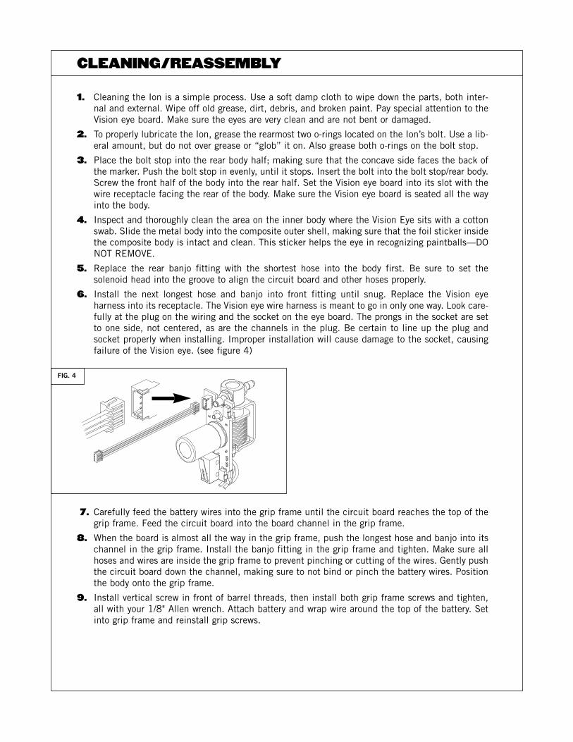
6. Install the next longest hose and banjo into front fitting until snug. Replace the Vision eye harness into its receptacle. The Vision eye wire harness is meant to go in only one way. Look care-fully at the plug on the wiring and the socket on the eye board. The prongs in the socket are setto one side, not centered, as are the channels in the plug. Be certain to line up the plug andsocket properly when installing. Improper installation will cause damage to the socket, causingfailure of the Vision eye. (see figure 4)
7. Carefully feed the battery wires into the grip frame until the circuit board reaches the top of thegrip frame. Feed the circuit board into the board channel in the grip frame.
8. When the board is almost all the way in the grip frame, push the longest hose and banjo into itschannel in the grip frame. Install the banjo fitting in the grip frame and tighten. Make sure allhoses and wires are inside the grip frame to prevent pinching or cutting of the wires. Gently pushthe circuit board down the channel, making sure to not bind or pinch the battery wires. Positionthe body onto the grip frame.
9. Install vertical screw in front of barrel threads, then install both grip frame screws and tighten,all with your 1/8" Allen wrench. Attach battery and wrap wire around the top of the battery. Setinto grip frame and reinstall grip screws.
CLEANING/REASSEMBLY
FIG. 4
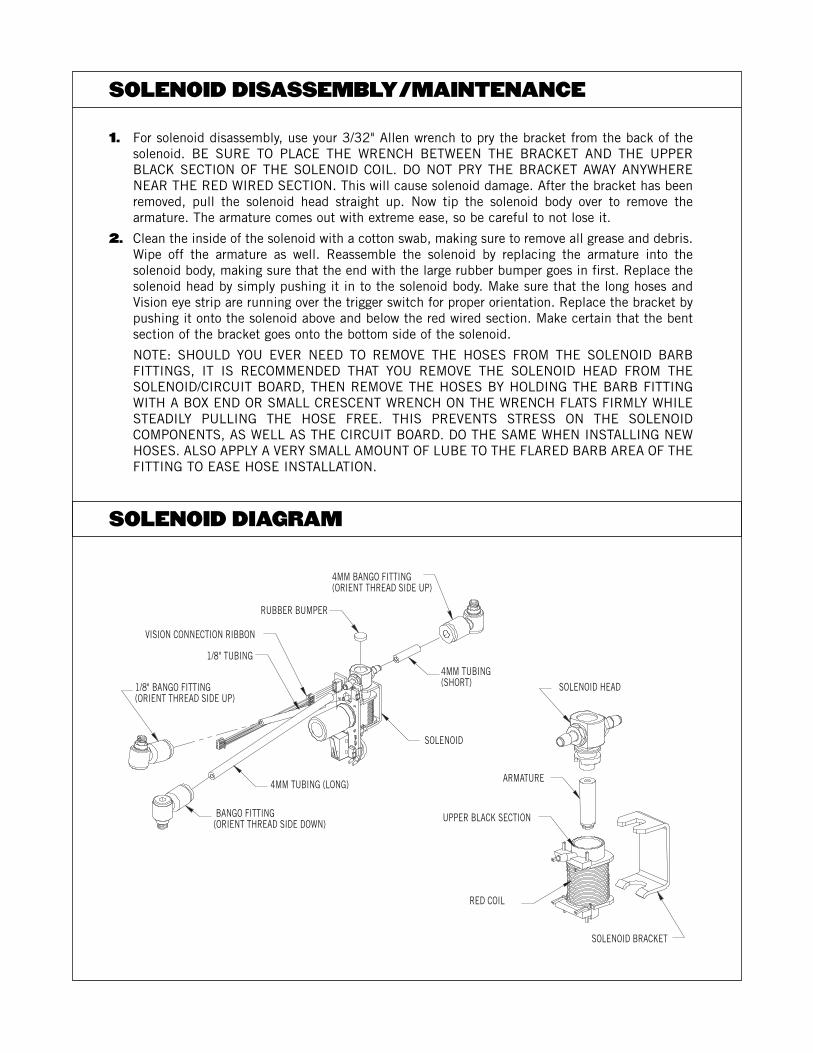
1. For solenoid disassembly, use your 3/32" Allen wrench to pry the bracket from the back of thesolenoid. BE SURE TO PLACE THE WRENCH BETWEEN THE BRACKET AND THE UPPERBLACK SECTION OF THE SOLENOID COIL. DO NOT PRY THE BRACKET AWAY ANYWHERENEAR THE RED WIRED SECTION. This will cause solenoid damage. After the bracket has beenremoved, pull the solenoid head straight up. Now tip the solenoid body over to remove the armature. The armature comes out with extreme ease, so be careful to not lose it.
2. Clean the inside of the solenoid with a cotton swab, making sure to remove all grease and debris.Wipe off the armature as well. Reassemble the solenoid by replacing the armature into the solenoid body, making sure that the end with the large rubber bumper goes in first. Replace thesolenoid head by simply pushing it in to the solenoid body. Make sure that the long hoses andVision eye strip are running over the trigger switch for proper orientation. Replace the bracket bypushing it onto the solenoid above and below the red wired section. Make certain that the bentsection of the bracket goes onto the bottom side of the solenoid.
NOTE: SHOULD YOU EVER NEED TO REMOVE THE HOSES FROM THE SOLENOID BARB FITTINGS, IT IS RECOMMENDED THAT YOU REMOVE THE SOLENOID HEAD FROM THE SOLENOID/CIRCUIT BOARD, THEN REMOVE THE HOSES BY HOLDING THE BARB FITTINGWITH A BOX END OR SMALL CRESCENT WRENCH ON THE WRENCH FLATS FIRMLY WHILESTEADILY PULLING THE HOSE FREE. THIS PREVENTS STRESS ON THE SOLENOID COMPONENTS, AS WELL AS THE CIRCUIT BOARD. DO THE SAME WHEN INSTALLING NEWHOSES. ALSO APPLY A VERY SMALL AMOUNT OF LUBE TO THE FLARED BARB AREA OF THEFITTING TO EASE HOSE INSTALLATION.
SOLENOID DISASSEMBLY/MAINTENANCE
SOLENOID DIAGRAM
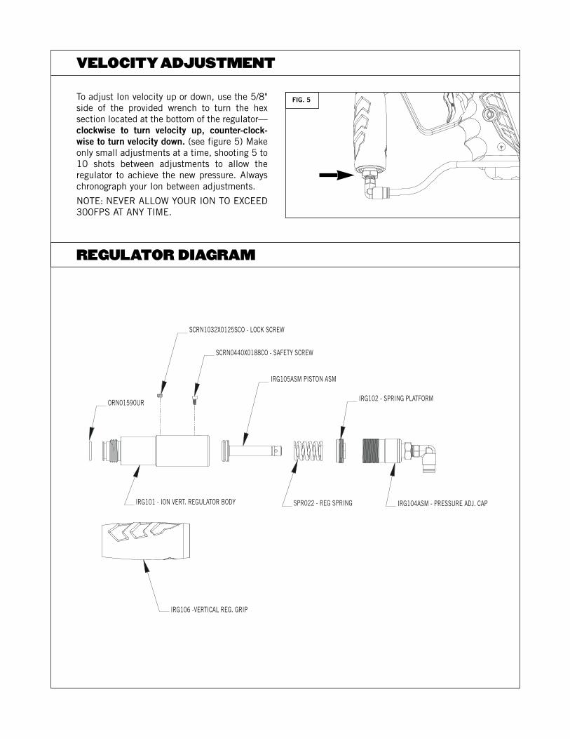
To adjust Ion velocity up or down, use the 5/8"side of the provided wrench to turn the hex section located at the bottom of the regulator—clockwise to turn velocity up, counter-clock-wise to turn velocity down. (see figure 5) Makeonly small adjustments at a time, shooting 5 to10 shots between adjustments to allow the regulator to achieve the new pressure. Alwayschronograph your Ion between adjustments.
NOTE: NEVER ALLOW YOUR ION TO EXCEED300FPS AT ANY TIME.
VELOCITY ADJUSTMENT
REGULATOR DIAGRAM
FIG. 5
NOTE: ALL THREADS IN THE ION REGULATOR ARE REVERSE THREADED. THIS MEANS THATTURNING THE INTERNAL PARTS CLOCKWISE LOOSENS, RATHER THAN TIGHTENS, THE PARTS.TURNING PARTS COUNTER-CLOCKWISE TIGHTENS THE PARTS.
1. Make sure the Ion is completely degassed.
2. Remove the regulator from the Ion by unthreading it counter-clockwise from the marker assem-bly. The vertical disc filter will come free as well when you do this. Check the filter for damage or debris, then set aside.
3. Remove the rubber outer grip sleeve by pushing from the bottom up. Set aside.
4. Using the provided 3/32" Allen Wrench, remove both set screws on the regulator body. One screwis located on the outside of the regulator body, about halfway up. The other is located inside anoval shaped hole near the bottom of the body. To remove this screw, you may have to turn thevelocity adjuster with the provided 5/8" wrench to get the screw lined up in the oval slot.
5. Using the 5/8" end of the provided wrench, completely remove the velocity adjuster by turningthe adjuster clockwise until free from the regulator body. Set aside.
6. Using a 9/16" deep well socket, turn the internal brass hex socket clockwise (right) until it comesfree. As the brass hex piece comes free, so will the regulator spring.
7. Using the provided 1/8" Allen Wrench, push the piston/regulator seat from the top of the regulator body out through the bottom until free.
Thoroughly clean all the regulator parts by simply wiping clean with a paper towel or soft cloth.Lubricate both o-rings on the piston assembly. DO NOT LUBRICATE THE REGULATOR SEAT locatedat the end of the piston section OR the large o-ring located around the velocity adjuster.
1. Push the piston/regulator seat, large end first, into the regulator body until it stops.
2. Slip the regulator spring over the end of the piston inside the regulator body.
3. Reinsert the brass hex piece and secure by turning the 9/16" deep well socket counter-clockwiseuntil snug. If you have installed the correctly, brass will be visible through the set screw hole inthe regulator body.
4. Replace the velocity adjuster by threading in counter-clockwise the lower set screw hole appearsin the oval slot on the regulator body.
5. Replace both set screws into the regulator body until snug. Use a very small amount of blue(#242) Loctite or clear nail polish on the set screw threads in the velocity adjuster (inside theoval slot) during reassembly. DO NOT OVER TIGHTEN. Now slowly turn the adjuster all the wayin counter-clockwise (left) until it stops. This will ensure that that the regulator is supplying nopressure into the marker.
6. Slip rubber outer grip over the top of the regulator body until it stops.
7. Gas up the Ion then turn the pressure up by using the included 5/8" wrench and slowly turningthe velocity adjuster up (clockwise) until you reach 180psi. Be sure to cycle the Ion five to tenshots between adjustments.
REGULATOR DISASSEMBLY/MAINTENANCE
REGULATOR REASSEMBLY
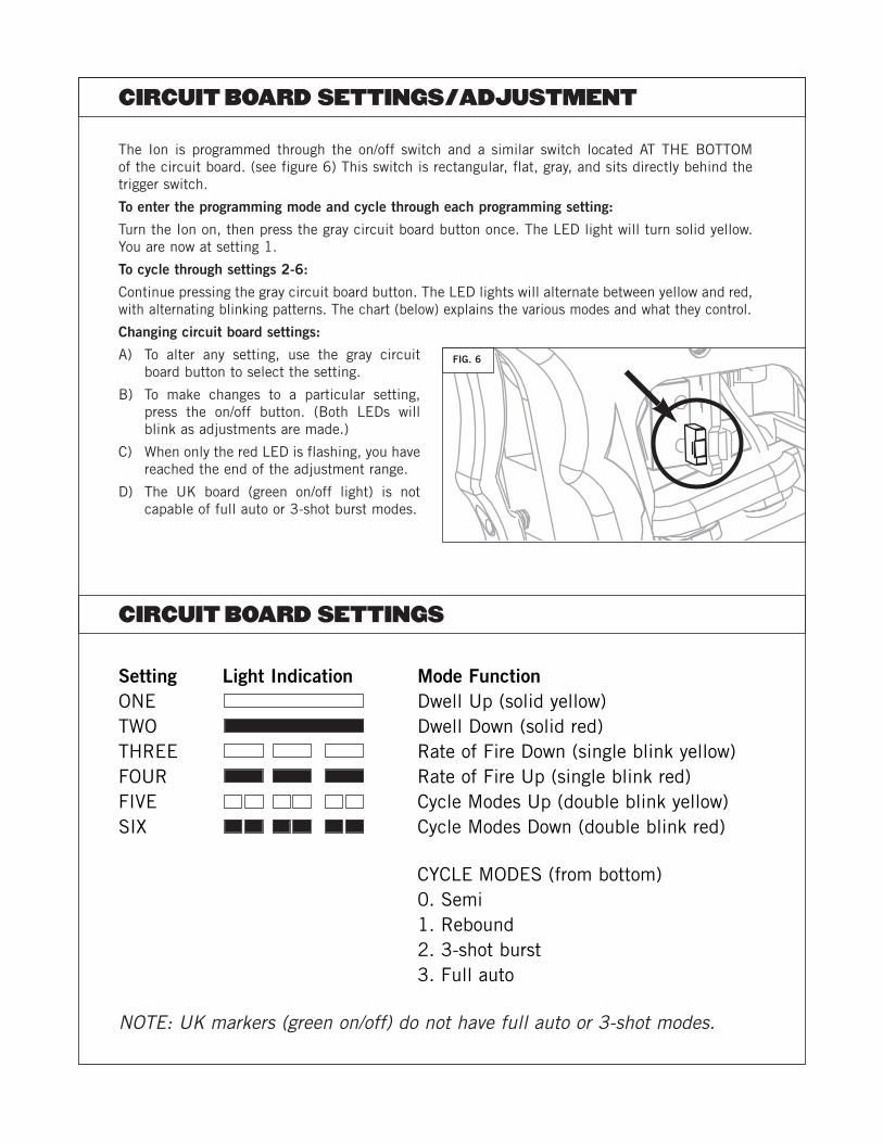
Setting Light Indication Mode FunctionONE Dwell Up (solid yellow)TWO Dwell Down (solid red)THREE Rate of Fire Down (single blink yellow)FOUR Rate of Fire Up (single blink red)FIVE Cycle Modes Up (double blink yellow)SIX Cycle Modes Down (double blink red)
CYCLE MODES (from bottom) 0. Semi 1. Rebound2. 3-shot burst3. Full auto
NOTE: UK markers (green on/off) do not have full auto or 3-shot modes.
The Ion is programmed through the on/off switch and a similar switch located AT THE BOTTOM of the circuit board. (see figure 6) This switch is rectangular, flat, gray, and sits directly behind thetrigger switch.
To enter the programming mode and cycle through each programming setting:
Turn the Ion on, then press the gray circuit board button once. The LED light will turn solid yellow.You are now at setting 1.
To cycle through settings 2-6:
Continue pressing the gray circuit board button. The LED lights will alternate between yellow and red,with alternating blinking patterns. The chart (below) explains the various modes and what they control.
Changing circuit board settings:
A) To alter any setting, use the gray circuitboard button to select the setting.
B) To make changes to a particular setting,press the on/off button. (Both LEDs willblink as adjustments are made.)
C) When only the red LED is flashing, you havereached the end of the adjustment range.
D) The UK board (green on/off light) is notcapable of full auto or 3-shot burst modes.
CIRCUIT BOARD SETTINGS/ADJUSTMENT
CIRCUIT BOARD SETTINGS
FIG. 6

CAUTION: EXTREME TRIGGER ADJUSTMENTS (IN EITHER SCREW) CAN CAUSE THE ION TO NOTFIRE AND/OR DAMAGE THE TRIGGER SWITCH. MAKE CHANGES GRADUALLY AND MODERATELY.
The Ion is equipped with an adjustable trigger. The length of the trigger stroke, tension and the trigger stop point can all be adjusted through two set screws.
1. Located near the bottom of the trigger, this screw is adjusted with the provided .050" Allenwrench. Turning the screw in stops the trigger sooner after the trigger fires the Ion. Turning it outstops it later in the trigger cycle, making the trigger “sloppier”. (see figure 7)
2. The other adjustment is the magnetic tension/pre-travel screw. It is located behind the triggerguard, just above the rubber grip. This screw shortens or lengthens the distance the trigger trav-els before the trigger switch is activated, as well as the magnetic tension of the trigger. The easiest way to adjust this screw is to remove the left sidegrip screws (side with gauge) and foldthe grip behind the trigger guard. Turning the screw in brings the trigger closer to the triggerswitch, shortening the trigger pull and making it “snappier”. (see figure 8)
TRIGGER ADJUSTMENT
FIG. 7 FIG. 8
THE ION IS LEAKING.A) INTERNALLY:— The pneumatic hoses are loose, damaged or not fully connected.Replace hoses with Smart Parts
Ion hoses only. — One or more of the pneumatic banjo fittings is loose or damaged. Tighten banjo fitting(s) or
replace with Smart Parts Ion banjo fittings only.— The solenoid armature is damaged or over pressurized. Replace armature and/or turn down oper-
ating pressure to less than 200psi.— The Ion is leaking down the barrel. One or more of the bolt o-rings and/or the bolt stop o-rings
are damaged. Replace immediately. B) EXTERNALLY:— The macro line air fittings are venting or leaking air. Degas the Ion, push the macro line hose all
the way into the fitting, then pull the hose back in the fitting, being certain that it catches andseals. If this does not work, replace the macro line hose with a new piece.
— Air is leaking from in and/or around the regulator. The bottle o-ring at the regulator top is damaged. Replace it.
— The regulator seat is contaminated and/or damaged. Replace with Smart Parts regulator seat only.(The regulator seat can be turned over and reused once.)
THE ION IS INCONSISTENT OR SHOOTS DOWN.— The barrel bore size is wrong for your paint. Adjust bore size or choose better quality paintballs. — The Ion’s air source is low. Fill up your tank and make sure your tank is all the way on. — The Ion’s battery is low. Replace with a high quality 9 volt battery.— The regulator seat is contaminated or damaged. Replace with Smart Parts regulator seat only.— The SFT o-ring, located inside the metal inner body, in front of the ball detents, is damaged,
swollen, or missing. Replace with Smart Parts 17/90 o-ring only.— Liquid CO2 is entering the regulator. Install an anti-siphon tube or use compressed air.
THE ION TURNS ON, BUT WILL NOT FIRE.— The battery is low or dead. Replace immediately. — The solenoid is clogged. Disassemble solenoid, clean armature and inside the solenoid body, then
reassemble WITHOUT lubrication. — One or more of the trigger set screws are adjusted too far in, putting pressure on the trigger
switch. Back screws out until trigger will activate the marker. — The trigger switch is damaged. Call Smart Parts or your local pro-shop for circuit board repair or
replacement. — Regulator pressure is too high (above 300 psi). Lower pressure and/or replace regulator seat. — Liquid CO2 is entering the regulator. Install an anti-siphon tube or use compressed air.
THE ION BREAKS PAINT.— The Ion’s battery is low. Replace with a high quality 9 volt battery.— The ball detents are worn. Replace with Ion ball detents only.— The barrel bore size is wrong for your paint. Adjust bore size or choose better quality paintballs. — The dwell of the Ion is too high. Lower in 3 click increments. Retest in between adjustments. — The eyes are off. Place Ion into Vision mode.— The eyes are covered with paint, allowing the Ion to shoot without paintballs, even in Vision mode.
Clean Vision eyes, as well as the slot they sit in, then reinstall.— The eyes are damaged or covered with paint or debris. Clean or replace the eye board. — The eye board wiring harness is damaged from improper installation. Replace.— Liquid CO2 is entering the regulator. Install an anti-siphon tube or use compressed air.
TROUBLESHOOTING
THE BIGGEST ENEMY OF THE ION, AND ANY PAINTBALL MARKER, IS LIQUID CO2.
Gas state CO2 is the preferred type of CO2 used to power paintball markers. Liquid CO2 is the moredense and liquefied version of the gas CO2 used to power markers. Liquid CO2 can, and will damageseals in the Ion as well as a massive chilling in certain temperatures, causing failure of the marker.Liquid CO2 is found, at least a little, in every filled CO2 tank. The cooler and more humid it gets, aswell as how fast you shoot continuously, the more liquid CO2 will form from the gas CO2 in your tank,causing shoot down, freezing, massive velocity spikes, and seal damage.
In the Ion, the biggest thing to look for is liquid CO2 creeping into the regulator, causing it to riseabove 200psi. The safest thing to do is to shut the air off and allow the Ion to warm up. This shouldbe easy with any on/off valve, simply shut the valve off, and, if possible shoot out the excess pres-sure. DO NOT REMOVE THE TANK FROM THE MARKER UNLESS ABSOLUTELY NECESSARY IN THIS SITUATION. If liquid CO2 is a persistent problem, you should have an anti-siphon tube, as well as an on/off valve, installed by Smart Parts or your local dealer. If you areuncertain as to what you should do, ask a qualified person as soon as possible.
DO NOT ATTEMPT TO WORK ON A PRESSURIZED MARKER IF YOU DO NOT KNOW WHAT YOUARE DOING.
Smart Parts warrants for one (1) year to initial retail purchaser that the paintball marker and regulator are free from defects in materials and workmanship. Disposable parts (batteries, o-rings, seals, etc.) are not warranted. The valve assembly is warranted for six (6) months. Thesolenoid and electronics on the marker are warranted for six (6) months, plus an additional warranty of six months for electronic parts only (instal-lation and labor are not included.) This warranty does not cover surface damages (scratches and nicks), misuse, improper disassembly and re-assembly, attempts made to drill holes or remove metal from the external surfaces which could degrade performance and reduce pressuresafety factors of the marker. Do not make changes to the basic marker parts without written approval. The only authorized lubricant for the mark-er is DOW 33 Lubricant. Use of any other lubricant could result in voiding your warranty. Paintball markers are non-refundable. This warranty islimited to repair or replacement of defective parts with the customer to pay shipping costs. This warranty is effective only if the customer returnsthe warranty registration card enclosed with the marker. The warranty is non-transferrable. Do not attempt to alter the trigger assembly in anyway, as this will void your Smart Parts Inc. warranty. Trigger alteration of any kind may result in serious injury.
Smart Parts, Inc.100 Station StreetLoyalhanna, PA 15661
Hours (EST)M-F 10-6
800-992-2147smartparts.com
West Coast Repair Center27326 Jefferson Ave #12Temecula, CA 92590
Hours (PST)7 Days 11-6
800-992-2147smartparts.com
European Repair CenterUnit 3 Old Bexley Business Park19 Bourne Road, Bexley, KentDA5 1LR England
HoursM-F 9-6, Saturday 10-4
++44 (0)1322 555968smartpartseurope.co.uk
WARNING: LIQUID CO2 COULD DAMAGE YOUR ION
WARRANTY
TECH SUPPORT
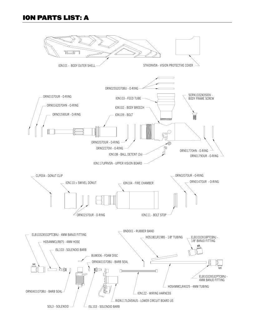
ION PARTS LIST: A
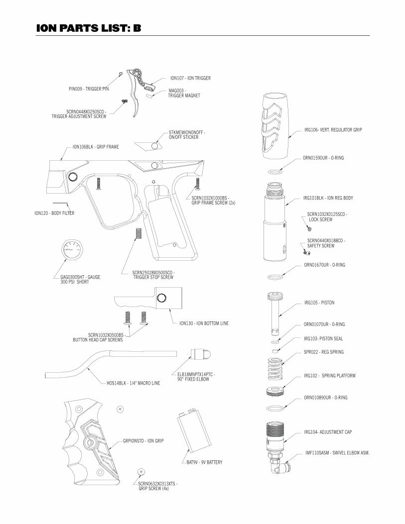
ION PARTS LIST: B

P. O . B O X 3 2 0 0 | L AT R O B E , PA 15 6 5 0 | 8 0 0 . 9 9 2 . 2 1 4 7 | S M A R T PA R T S . C O M