Embed Size (px)
Citation preview

Smart Materials Actuators: Actuated Scissor Lift
Luís Filipe Araújo de Oliveira Mestrado Integrado em Engenharia Física Departamento de Física e Astronomia, FCUP 2018 Orientador André Miguel Trindade Pereira, Professor Auxiliar, Departamento de Física e Astronomia Faculdade de Ciências da Universidade do Porto Coorientadores Joana Fonseca, CeNTI, Ricardo Carvalho, CeNTI


Todas as correções determinadas pelo júri, e só essas, foram efetuadas.
O Presidente do Júri,
Porto, / /

UNIVERSIDADE DO PORTO
MASTERS THESIS
Smart Materials Actuators: Actuated Scissor Lift
Author: Supervisor:
Luís OLIVEIRA André PEREIRA
Co-supervisor:
Joana FONSECA
Ricardo CARVALHO
A thesis submitted in fulfilment of the requirements for the degree of Master of Science
at the
Faculdade de Ciências
Departamento de Física e Astronomia
IFIMUP and CeNTI
September 2018

Declaration of Authorship
I, Luís Filipe Araújo de Oliveira, declare that this thesis titled, Smart Materials Actuators: Actuated Scissor Lift and the work presented in it are my own. I confirm that:
• This work was done wholly or mainly while in candidature for a research
degree at this University.
• Where any part of this thesis has previously been submitted for a degree or any other qualification at this University or any other institution, this has been clearly stated.
• Where I have consulted the published work of others, this is always clearly attributed.
• Where I have quoted from the work of others, the source is always given. With the exception of such quotations, this thesis is entirely my own work.
• I have acknowledged all main sources of help.
• Where the thesis is based on work done by myself jointly with others, I have made clear exactly what was done by others and what I have contributed myself.
Signed:
Date:


“If I have seen further it is by standing on the shoulders of giants. “
- Isaac Newton

iv
v
Preface
Dear reader,
To me, this work has been a thrilling closure for my time as a student. Throughout this project, which consisted of an internship at CeNTI, I put into practise several tools I have acquired over the past 5 years, in the fields of mathematics, physics, material science, electronics, optics, and computing. I feel like I have grown from a student to a professional with regard to scientific and technological problem-solving.
I would describe myself as a curious person, who tries to embark on new adventures and to combine multidisciplinary know-how. Working in an R&D business environment has been a thrilling opportunity to develop myself in different areas. Concluding my masters with a project in which brainstorming was combined with a hands-on approach was exactly what I wanted. Working together with professionals in the scientific and business world for nine months was a very valuable experience.
On the way, I have learned about physics, people and imagination, which I consider to be the fundamentals of the way we perceive the world, challenge ourselves and the way we shape the future. I hope you can appreciate my work, embodied in this thesis.
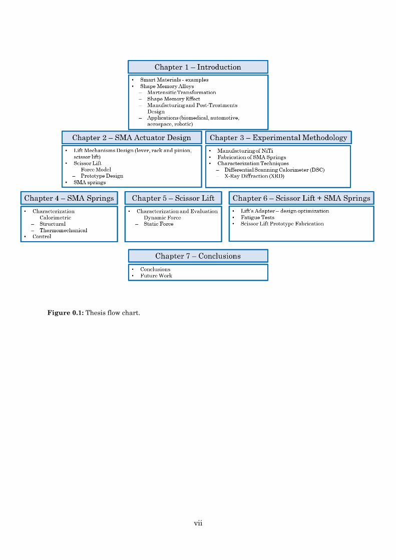
This thesis is organised into 7 chapters as illustrated in the thesis map (Figure 0.1). Chapter 1 introduces a comprehensive overview of smart materials, with special emphasis on Shape Memory Alloys (SMAs). It started with an explanation of the physical concept (martensitic transformation) and the effect based on it (shape memory effect). The manufacturing and post-treatments of SMAs are briefly introduced in this chapter. The advantages, limitations and common designs of SMAs are also pointed in this chapter, as the performance of the alloys relies deeply on their composition and design. There were also appointed several technological applications, ranging from biomedical to more recently robotic industry.
Chapter 2 analyses different possible lift mechanisms triggered by an SMA spring, their advantages, limitations and associated design challenges. The design of an Actuated SMA Scissor Lift prototype is presented along with a physical model regarding its force output. Finally, it is described the design approach regarding SMA springs, which includes geometry and force modelling.
vi
Chapter 3 reviews the existing manufacturing processes of nitinol followed by the fabrication methodology, employed in this work, for obtaining SMA springs from wires. Next is presented a brief overview on techniques for calorimetric and structural characterization, as Differential Scanning Calorimeter (DSC) and X-Ray Diffraction (XRD).
Chapter 4 investigates the effect of stress (when annealing SMA springs) on transformation temperatures and phase transition behaviour. Experimental methodology and results concerning the austenite shear modulus are presented. Afterwards, by using an Arduino it was possible to control the voltage across the spring. Dynamic parameters such as power, temperature and response time were investigated.
Before placing the SMA into the final prototype, a scissor lift evaluation was intended. In chapter 5, force and displacement characterization tests with a commercial scissor lift are presented.
Chapter 6 evaluates the performance of a commercial scissor lift actuated with SMA springs. Design optimization concerning the assembly of the lift with the SMA springs is scrutinized. Also, by integrating a distance sensor in the apparatus it was possible to have an insight about the alloy’s fatigue life. After all, it is presented the fabrication of the acrylic prototype of a Scissor Lift.
Finally, Chapter 7 summarises the performed work and recommends potential relevant future research and development.
I hope you enjoy your reading!
Luís Oliveira
vii
Figure 0.1: Thesis flow chart.

viii

ix
Acknowledgements
Before diving into the exploration of this master thesis, I would like to acknowledge all the people who helped me composing it during this last year.
First and foremost, I would like to express my sincerest gratitude to my supervisor Prof. Doctor André Pereira. His support, advice and expertise were fundamental to my motivation, not only during this project but since I entered the university. He really cares about his students, even outside the academic world.
I would also like to extend my appreciation to my co-supervisors, Doctor Joana Fonseca and Ricardo Carvalho for their continuous support, guidance, and insightful advice, which were crucial to many decisions during the development of this work. It was truly a pleasure to work at CeNTI under their supervision. I am also very thankful to all the people who worked at CeNTI with me, as they always showed support and helpfulness.
Additionally, I would also like to thank Miguel Ramalho, an internship colleague who I had the pleasure to work with for almost two months. His opinions and suggestions were very relevant and helpful for the project and have boosted my motivation. We both benefited from sharing our know-how.
I owe a debt of gratitude to all the friends I made in the university. Studying physics for five years would have been even harder without them.
Last but not least, I’m eternally grateful to my parents for all the love, care, and sacrifice they did to shape my life. They are the main reason for my presence here today, always willing to support any decision I make, encouraging and providing me with all the necessary means for me to follow my dreams. Also, I express my thanks to my beloved little sister.

x

xi
Abstract
Nowadays the demand for sophisticated and specialized materials, as well as consideration of the environmental impact, has spawned a new branch of research into smart materials. Shape Memory Alloys (SMAs) are a unique class of smart materials with the ability to return to their original shape when heated after several deformations. SMAs can be used as both sensors and actuators due to their compactness, lightness, bio-compatibility, noiseless operation, high wear resistance and functionality. When set as springs, SMAs provide greater displacements, which are well suited for new and promising actuation mechanisms.
In this work, a scissor lift mechanism was successfully actuated by an SMA spring. Both physics of SMAs and actuation mechanisms were investigated, and the project culminated with the development of a scissor lift prototype. The prototype was lightweight, compact, and made of acrylic, able to lift 400 g by means of an SMA spring with 1 cm long and an outside diameter of 57 mm.
Aiming to achieve this goal, several contributions were made regarding SMA actuators. First, it was developed an improved fabricating method to shape set wires into tightly springs without spacing between coils, ranging from 5.7 to 7.7 mm outside diameter. Then, a spreadsheet, based on the state-of-art equations of SMA springs, was developed. Fatigue tests were also performed and have shown that when the alloy was subjected to strains of about 10%, his displacement under actuation has decreased.
Thermal, structural and mechanical characterization of SMAs were studied. The austenitic shear modulus was estimated to be G≅13.09 GPa and a maximum force of 34 N and 2.4 cm displacement were obtained with a 5.7 mm OD spring. DSC and XRD measurements revealed the presence of an intermediate phase, R-phase, in springs subjected to greater torsion forces and stress upon annealing. Also, Differential Scanning Calorimeter measurements have shown that the transformation temperatures and fusion enthalpies increase with increasing the stress levels. To control the amount of voltage for a certain period across an SMA spring, a control system, based on a microcontroller, was developed. When subjected to an electrical power of 1.377 W, a 67 mm OD spring has reached the transition temperature (∼70 °C) in about 30 s and it took about 7 min to cool.
The prototype force requirements were assessed with a commercial laboratory scissor jack, where it was obtained a spring stroke and force of about 3 cm and 17 N,

xii
respectively. Furthermore, a part that assembles the spring together with the scissor lift was designed, produced and optimized.
xiii
Resumo
Atualmente, a crescente procura por produtos inovadores, eficientes e sustentáveis despertou o interesse na investigação em materiais técnicos, funcionais e inteligentes. As ligas com memória de forma (Shape Memory Alloys) são materiais metálicos inteligentes com a capacidade de voltar à sua forma original, quando aquecidos e após várias deformações. Os SMAs podem ser usados como sensores e atuadores devido ao seu carácter compacto, leve, biocompatível, silencioso, resistente e funcional. Ao serem “memorizados” sob a forma de molas, proporcionam maiores deslocamentos, podendo ser utilizados em mecanismos de atuação inovadores.
Neste trabalho, foi desenvolvido com sucesso um mecanismo de elevação em tesoura atuado por uma mola SMA. Investigou-se o fenómeno físico dos SMAs, bem como os seus mecanismos de atuação, e o projeto culminou na produção de um scissor lift. O protótipo feito em acrílico, mostrou-se leve e compacto, e foi capaz de levantar 400 g através de uma mola SMA com 1 cm de comprimento e 57 mm de diâmetro externo.
De forma a atingir este objetivo foram feitas várias contribuições em relação aos atuadores SMA. Primeiro, desenvolveu-se um método de fabricação de molas a partir de fios. Obtiveram-se molas compactas, sem espaçamentos entre espiras, com diâmetros externos entre 5.7 a 7.7 mm. De seguida, foi elaborada uma folha de cálculo para projetar molas, com base nas equações encontradas na literatura. Foram também realizados testes de fadiga que evidenciaram que quando o material é sujeito a strains de 10%, a capacidade de voltar à sua forma original diminuí.
Os SMAs foram também caracterizados térmica, estrutural e mecanicamente.
Estimou-se o valor de G≅13.09 GPa para o shear modulus na fase austenítica. Obteve-se uma força máxima de 34 N e um deslocamento de 2.4 cm com uma mola de 57 mm de diâmetro externo. Os resultados do DSC e XRD revelaram a presença de uma fase intermédia, R-phase, nas molas sujeitas a pressões elevadas aquando da fase de annealing. Os resultados do DSC mostraram também que as temperaturas de transição de fase e as entalpias de fusão aumentam com o aumento da pressão. Foi também desenvolvido um sistema de controlo, com base num microcontrolador, de forma a controlar a diferença de potencial numa mola SMA durante um certo período. Quando submetida a uma potência elétrica de 1.377 W, uma mola de 67 mm de diâmetro externo atingiu a temperatura de transição (∼70 ° C) em cerca de 30 s, e levou cerca de 7 minutos para arrefecer.

xiv
Os requisitos de força para o protótipo obtiveram-se realizando testes num scissor
lift de laboratório, onde se obteve uma força de 17 N e um deslocamento de 3 cm. Por último, produziu-se e otimizou-se uma peça que une a mola SMA ao scissor lift.
xv
Contents
Preface ................................................................................................................................... v
Acknowledgements .............................................................................................................. ix
Abstract ............................................................................................................................... xi
Resumo .............................................................................................................................. xiii
Contents .............................................................................................................................. xv
List of Figures ................................................................................................................. xviii
List of Tables .................................................................................................................... xxii
Abbreviations .................................................................................................................. xxiii
1. Introduction .................................................................................................................. 1
1.1 Smart Materials ..................................................................................................... 1
1.2 Shape Memory Alloys (SMAs) ............................................................................... 2
1.2.1 Martensitic Transformation ........................................................................... 2
1.2.2 Shape Memory Effect...................................................................................... 3
1.3 NiTi Based Alloys .................................................................................................. 6
1.4 Manufacturing of SMAs......................................................................................... 7
1.4.1 Melting process ............................................................................................... 7
1.4.2 Post-Treatments ............................................................................................. 8
1.5 Design of SMA actuators ....................................................................................... 9
1.6 Overview of SMA Applications .............................................................................10
1.6.1 Biomedical Applications ................................................................................10
1.6.2 Aerospace Applications ..................................................................................12
1.6.3 Automotive Applications ...............................................................................13
1.6.4 Robotic Applications ......................................................................................16
1.7 CeNTI and Project Objectives ..............................................................................19
2. Design of an SMA Actuator .........................................................................................21
xvi
2.1 Lift Mechanisms Design .......................................................................................21
2.1.1 Lever ..............................................................................................................21
2.1.2 Rack and Pinion .............................................................................................23
2.1.3 Scissor Lift .....................................................................................................24
2.2 Scissor Lift Design ................................................................................................25
2.2.1 Force Model ....................................................................................................25
2.2.2 Prototype Design of the SMA Actuated Scissor Lift .....................................27
2.3 Design of SMA springs .........................................................................................29
2.3.1 Geometry and Force Modelling of NiTi springs ............................................29
3. Experimental Methodology of NiTi SMA components ................................................33
3.1 Manufacturing Process of NiTi SMAs ..................................................................33
3.1.1 Vacuum Induction Melting (VIM) .................................................................34
3.1.2 Vacuum Arc Remelting (VAR) .......................................................................35
3.2 Fabrication of SMA springs ..................................................................................35
3.3 Characterization Techniques ...............................................................................38
3.3.1 Differential Scanning Calorimeter (DSC) .....................................................38
3.3.2 X-Ray Diffraction (XRD) ................................................................................39
4. Characterization and Control of SMA Springs ...........................................................41
4.1 Characterization of SMA ......................................................................................41
4.1.1 Calorimetric Analysis ....................................................................................41
4.1.2 Structural Characterization ..........................................................................45
4.1.3 Thermomechanical Characterization ............................................................46
4.2 Control of SMA .....................................................................................................48
4.2.1 Power and Temperature Behaviour ..............................................................48
5. Evaluation of Prototype Requirements .......................................................................55
5.1 Dynamic Force Tests ............................................................................................55
5.2 Static Force Tests .................................................................................................57
6. SMA Actuated Scissor Lift ..........................................................................................61
xvii
6.1 SMA Spring into Scissor Lift ................................................................................61
6.1.1 Lift’s Adapter .................................................................................................61
6.1.2 Fatigue tests ..................................................................................................67
6.1.3 Acrylic Scissor Lift Prototype ........................................................................69
7. Conclusion and Future Work ......................................................................................71
7.1 Conclusions ...........................................................................................................71
7.2 Future Work .........................................................................................................73
Appendix A: 3D Scissor Lift Drawings ...............................................................................75
Appendix B: SMA Springs Spreadsheet .............................................................................79
Bibliography ........................................................................................................................81
xviii
List of Figures Figure 0.1: Thesis flow chart. .......................................................................................... vii Figure 1.1: Schematic illustration of austenite and martensite crystal structures (adapted from [5]). ............................................................................................................................... 3
Figure 1.2: a) Crystal structures of martensite and austenite along with associated forward and backward transformation cases. After heating it transforms to the austenite phase where the atoms are rearranged into their original positions. When cooled it still keeps its original shape. ...................................................................................................... 4
Figure 1.3: Superelastic/pseudoelastic response of a SMA at three different temperatures [5]. ........................................................................................................................................ 6
Figure 1.4: Examples of alloys systems that show SME [5]. ............................................. 7
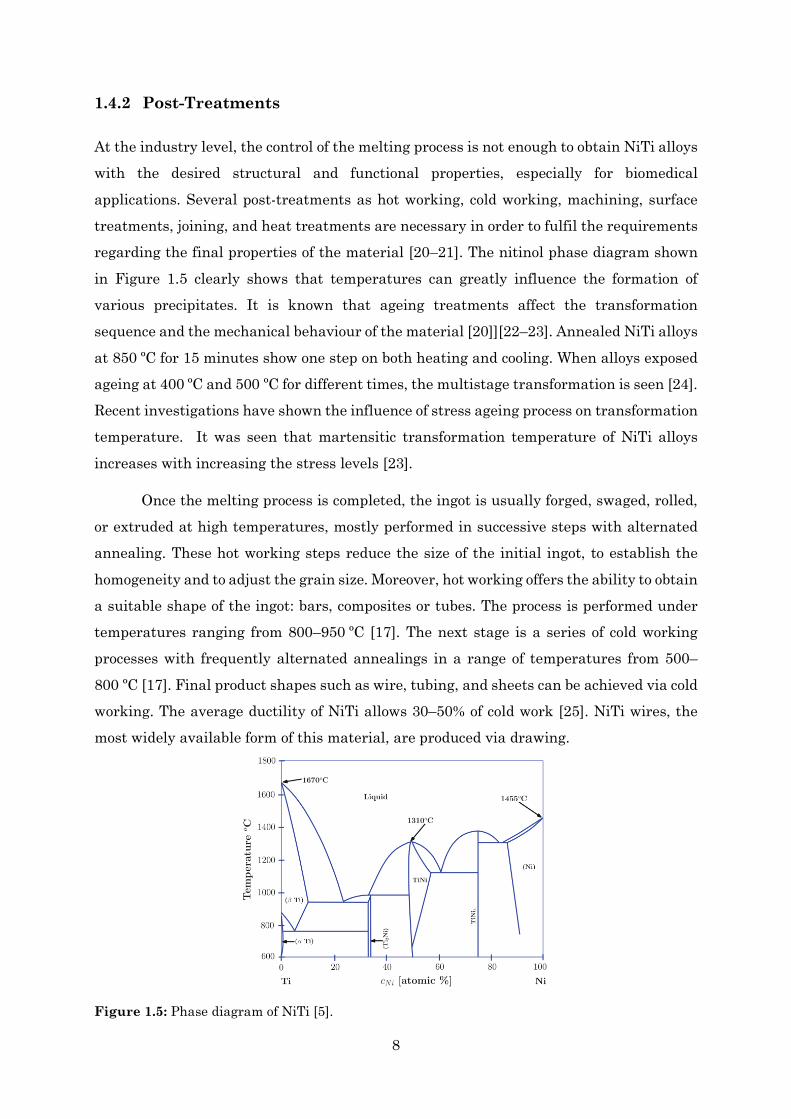
Figure 1.5: Phase diagram of NiTi [5]. .............................................................................. 8
Figure 1.6: Spring actuation cycle: a shape-set twinned martensite actuator is subjected to an external force, causing martensite detwinning; the actuator is heated, and austenite phase-change occurs leading to activation; subsequent cooling causes martensite phase-change, ending in the original twinned state [26]. ............................................................10
Figure 1.7: Existing and potential SMA applications in the biomedical domain [8]. ......11
Figure 1.8: Boeing’s variable geometry chevron (VGC) [8]. .............................................13
Figure 1.9: Existing and potential SMA applications in the aerospace domain [8]. .......13
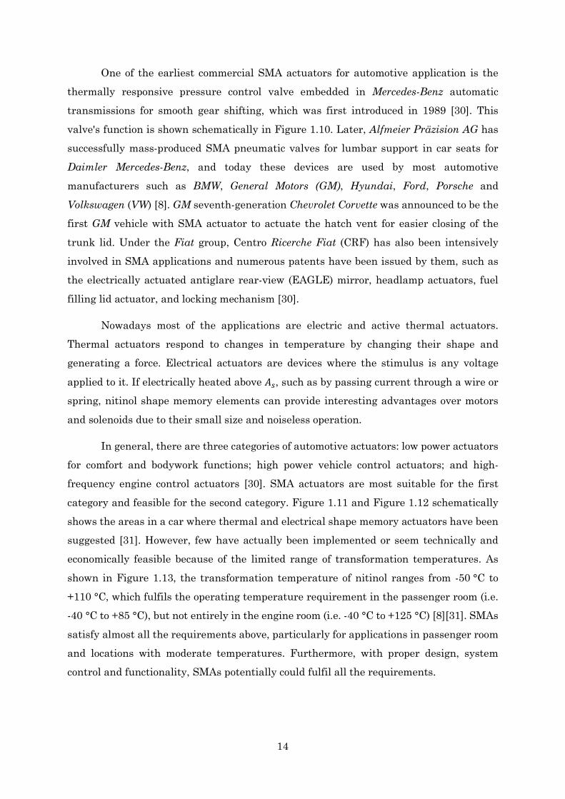
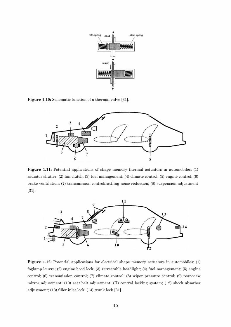
Figure 1.10: Schematic function of a thermal valve [31]. ................................................15
Figure 1.11: Potential applications of shape memory thermal actuators in automobiles: (1) radiator shutler; (2) fan clutch; (3) fuel management; (4) climate control; (5) engine control; (6) brake ventilation; (7) transmission control/rattling noise reduction; (8) suspension adjustment [31]. ...............................................................................................15
Figure 1.12: Potential applications for electrical shape memory actuators in automobiles: (1) foglamp louvre; (2) engine hood lock; (3) retractable headlight; (4) fuel management; (5) engine control; (6) transmission control; (7) climate control; (8) wiper pressure control; (9) rear-view mirror adjustment; (10) seat·belt adjustment; (II) central locking system; (12) shock absorber adjustment; (13) filler inlet lock; (14) trunk lock [31]. ......................15
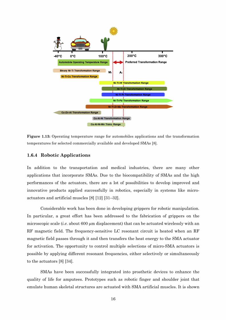
Figure 1.13: Operating temperature range for automobiles applications and the transformation temperatures for selected commercially available and developed SMAs [8]. .............................................................................................................................................16
Figure 1.14: BionicOpter by Festo. ...................................................................................17
xix
Figure 1.15: Existing and potential SMA applications in the robotic technology domain [8]. .......................................................................................................................................18
Figure 1.16: Project Overview. ..........................................................................................19
Figure 2.1: Illustration of a simple lever/seesaw mechanism with the load on one side and the SMA spring on the other ..............................................................................................22
Figure 2.2: Draft of the rack and pinion lift mechanism actuated by an SMA spring. ...23
Figure 2.3: Scheme of a 2 level scissor lift mechanism (adapted from [37]). ...................24
Figure 2.4: Design of a 1 level and 2 level scissor lift actuated with an SMA spring. ....25
Figure 2.5: Scheme of the geometry of a 2-level scissor lift mechanism. .........................26
Figure 2.6: External force on an SMA spring vs. angle between the scissor arm and the horizontal plane. Based on the model proposed by Spackman [38]. ..................................27
Figure 2.7: Isometric and side view of the Scissor Lift Prototype designed in OnShape. .............................................................................................................................................28
Figure 2.8: 3D CAD model of the SMA Actuated Scissor Lift. .........................................28
Figure 2.9: Spring parameters as defined by coil geometry, for both a fully compressed (solid) spring and a free-length spring [26]. .......................................................................30
Figure 3.1: Schematic of a VIM setup for producing NiTi alloys [5]. ...............................34
Figure 3.2: Pillar drilling machine used for wounding the wire around the screw thread. .............................................................................................................................................36
Figure 3.3: Shape setting fixture apparatus. A screw thread used to shape set nitinol wires into extension springs. Notice the use of wire rope clips to constrain the wire ends to prevent unwinding back to initial state. ........................................................................37
Figure 3.4: Furnace used for the annealing treatment and bucket with water and ice for cooling the SMA rapidly. ....................................................................................................37
Figure 3.5: SMAs springs fabricated from nitinol wires. .................................................37
Figure 3.6: Schematic of X-ray diffraction beam working principle [51]. ........................40
Figure 4.1: DSC results of the NiTi alloy spring with 6.7 mm outside diameter, annealed at 500 ºC for 15 min. ...........................................................................................................42
Figure 4.2: DSC charts on heating from 0 to 100 ºC under 10 ºC/min. The four DSC charts show the influence of stress on the transformation temperatures. ...................................43
Figure 4.3: a) Effect on transformation temperatures (As, Af, Tpeak) of NiTi alloys with increasing the stress levels (decrease of spring’s outside diameter). ................................44
Figure 4.4: XRD results of five NiTi alloys samples: one NiTi non-annealed wire; one NiTi annealed wire; three NiTi annealed springs, with outside diameters of 5.7, 6.7 and 7.7 mm respectively. ........................................................................................................................46
xx
Figure 4.5: Experimental apparatus for measuring spring’s force and elongation upon stress and heating. ..............................................................................................................48
Figure 4.6: Force vs. elongation curve for three NiTi annealed springs, with outside diameters of 5.7, 6.7 and 7.7 mm respectively. ..................................................................48
Figure 4.7: Control of the applied voltage across an SMA spring using an Arduino Nano. .............................................................................................................................................49
Figure 4.8: Experimental apparatus consisting in a voltmeter, an amperemeter and an ohmmeter for measuring, in real-time, voltage, current and temperature across a 6.7 mm OD spring. ...........................................................................................................................50
Figure 4.9: Resistance output across an SMA spring for different powers......................50
Figure 4.10: Temperature curves across a 6.7 mm OD spring for different powers........52
Figure 4.11: a) Heating and cooling behaviour of a SMA spring (80 % of maximum voltage). ...............................................................................................................................53
Figure 5.1: Experimental apparatus concerning the dynamic force characterization of the scissor lift ............................................................................................................................56
Figure 5.2: a) Dynamic force tests for ascending and descending cycles of a commercial scissor lift. ...........................................................................................................................56
Figure 5.3: Schematic of a wooden base for fixing the dynamometer and the scissor lift. .............................................................................................................................................58
Figure 5.4: Experimental apparatus concerning the static force characterization of the scissor lift. The custom wooden base helped to fix the dynamometer and the lift. ...........59
Figure 5.5: Experimental and theoretical static force vs lift's displacement curves. ......60
Figure 5.6: Comparison between experimental, theoretical and non-linear fit curves with respect to the non-load trial. ...............................................................................................60
Figure 6.1: Lift’s Adapter Design V1. ...............................................................................62
Figure 6.2: Scissor Lift actuated by a SMA spring using the V1.2 ABS adapter. ...........63
Figure 6.3: Lift’s adapter design V2. ................................................................................64
Figure 6.4: Scissor Lift actuated by a SMA spring using the V2 ABS adapter. ..............64
Figure 6.5: Twisted ABS adapters after the contraction of the SMA springs. ................65
Figure 6.6: a) Lift’s adapter design V3.1. b) Lift’s adapter design V3.2. .........................66
Figure 6.7: Scissor lift actuated by a SMA spring using the V3 ABS adapter. ...............66
Figure 6.8: Rise and descending time behaviour by increasing the mass of the load. ....67
Figure 6.9: Lift’s change in height behaviour regarding the first fatigue test performed over 39 minutes. ..................................................................................................................68

xxi
Figure 6.10: Lift’s change in height behaviour regarding all the fatigue tests put together. .............................................................................................................................................68
Figure 6.11: a) Acrylic parts regarding lift’s top, base and arms. ....................................69
Figure 6.12: Assembled acrylic scissor lift prototype. ......................................................70
Figure 6.13: Prototype lift actuated by a SMA spring using, without load. ....................70
Figure 6.14: Prototype lift actuated by a SMA spring using, with a load of 400 g. .........70

xxii
List of Tables Table 1.1: Examples of smart materials and their corresponding input and output signals. .............................................................................................................................................. 2
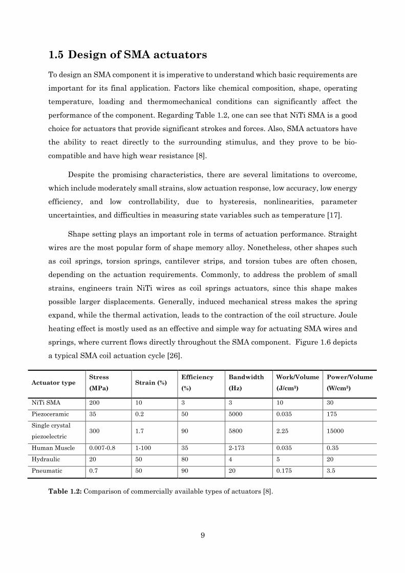
Table 1.2: Comparison of commercially available types of actuators [8]. ......................... 9
Table 2.1: Terms used in the design of SMA springs. ......................................................30
Table 4.1: Transformation temperatures and fusion enthalpies, obtained with DSC under 10 ºC/min, of one NiTi wire and three NiTi springs with 7.7, 6.7 and 5.7 mm outside diameter respectively. .........................................................................................................43
Table 4.2: Transformation temperatures and fusion enthalpies, obtained with DSC under 40 ºC/min, of one NiTi wire and three NiTi springs with 7.7, 6.7 and 5.7 mm outside diameter respectively. .........................................................................................................44
Table 4.3: Power measurements for an SMA spring for several percentages of voltage selected. ...............................................................................................................................50
Table 4.4: Power and temperature measurements regarding an SMA spring. ...............52
Table 5.1: Results for parameter b obtained from the non-linear curve fits. ...................58
Table 6.1: Results for displacement, rise time and descending time in the scissor lift actuated by an SMA spring. ...............................................................................................66
xxiii
Abbreviations
SMA Shape Memory Alloy
SME Shape Memory Effect
SE Super Elastic Effect
SIM Stress Induced Martensite
VIM Vacuum Induction Melting
VAR Vacuum Arc Melting
DSC Differential Scanning Calorimeter
XRD X-Ray Diffraction
ABS Acrylonitrile Butadiene Styrene
PCB Printed Circuit Board

xxiv
1
Chapter 1
1. Introduction
1.1 Smart Materials From the dawn of mankind, materials have been fundamental to the development of human societies. Indeed, civilizations have been named based on the level of their materials development (Stone, Copper, Bronze and Iron ages) [1]. The progress of many technologies that make our existence so comfortable has been intimately associated with the accessibility of suitable materials. An advancement in the understanding of a material type is often the forerunner to the stepwise progression of a technology [2]. For example, sophisticated electronic devices such as smartphones would not have been possible without the availability and study of semiconductors.
Over the past decades, massive advancements in science and technology contribute to a tremendous progress in the field of materials science [3]. The demand for sophisticated and specialized materials, as well as consideration of the environmental impact, has spawned a new branch of research into smart materials [4–5]. The adjective “smart” implies that these materials can react to their environment all by themselves when subjected to an external stimulus from their surrounding environment. In general, smart materials exhibit mechanical response when subjected to changes in temperature, electric fields, and/or magnetic fields [3–5]. Some examples of smart materials commonly used for actuators are: shape memory alloys; piezoelectric materials; magnetostrictive materials, electrorheological and magnetorheological fluids [6]. Table 1.1 summarizes some commonly used smart materials with their corresponding input signals and responses.

2
Material Input signal Output or response
Shape Memory Alloys (SMAs)
Change in temperature Change in length/shape
Piezoelectric Ceramics Electric field Deformation
Magnetostrictive Materials
Magnetic field Deformation
Shape Memory Polymers (SMPs)
pH/humidity/temperature/light intensity change
Change in shape
Magnetorheological Fluids (MR fluids)
Magnetic field Change in viscosity
Electrorheological Fluids (ER fluids)
Electric field Change in viscosity
Table 1.1: Examples of smart materials and their corresponding input and output signals.
1.2 Shape Memory Alloys (SMAs) Shape Memory Alloys (SMAs) are a unique class of smart materials with the ability to return to their original shape when heated. Once deformed at low temperatures SMAs will stay deformed until the temperature increases, whereupon they will spontaneously return to their original shape. This capability is referred to as the shape memory effect (SME) and was first observed in AuCd alloy in 1932 [7]. In the following years, the SME was observed in other alloys, such as NiTi, Fe–Mn–Si, Cu–Zn–Al and Cu–Al–Ni. However, NiTi based SMAs are much more preferable for most applications [8] [9–13].
1.2.1 Martensitic Transformation
It was only 20 years later that this phenomenon was attributed to the thermoelastic martensitic transformation, a specific type of a crystallographic phase transformation in the solid state [14]. SMAs may be found in two phases: austenite and martensite. Usually, the high-temperature phase austenite (β-phase) has a body-centred cubic structure (B2) as compared to the low-temperature phase martensite (α-phase) which has either tetragonal, orthorhombic or monoclinic structures [5]. Due to its low symmetry structure, each martensitic crystal formed can have a different orientation direction, called a variant [5]. Thus, there are two main martensite configurations: twinned martensite (𝑀𝑀𝑡𝑡), which is formed by a combination of “self-accommodated” martensitic variants, and detwinned
3
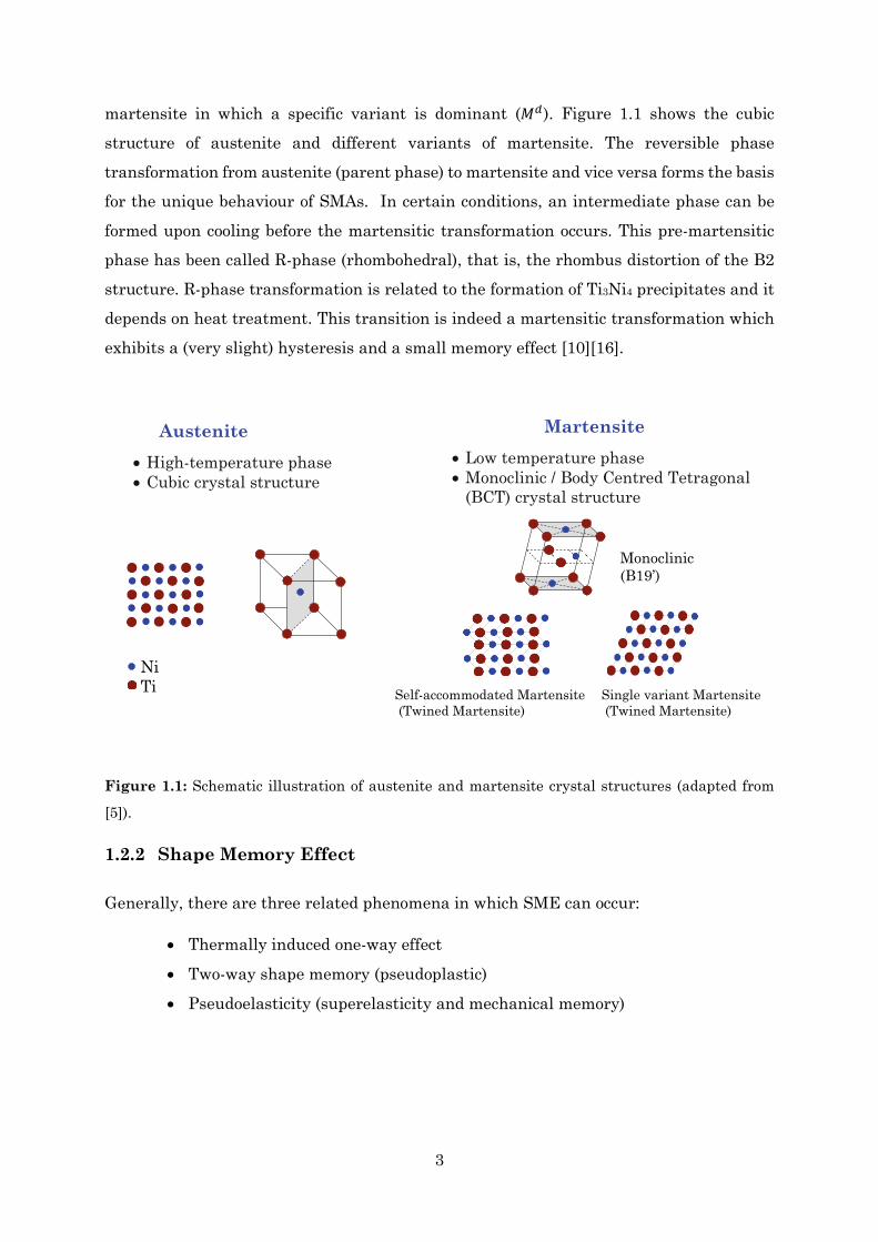
martensite in which a specific variant is dominant (𝑀𝑀𝑑𝑑). Figure 1.1 shows the cubic structure of austenite and different variants of martensite. The reversible phase transformation from austenite (parent phase) to martensite and vice versa forms the basis for the unique behaviour of SMAs. In certain conditions, an intermediate phase can be formed upon cooling before the martensitic transformation occurs. This pre-martensitic phase has been called R-phase (rhombohedral), that is, the rhombus distortion of the B2 structure. R-phase transformation is related to the formation of Ti3Ni4 precipitates and it depends on heat treatment. This transition is indeed a martensitic transformation which exhibits a (very slight) hysteresis and a small memory effect [10][16].
Austenite • High-temperature phase • Cubic crystal structure
1.2.2 Shape Memory Effect
Generally, there are three related phenomena in which SME can occur:
• Thermally induced one-way effect
• Two-way shape memory (pseudoplastic)
• Pseudoelasticity (superelasticity and mechanical memory)
Figure 1.1: Schematic illustration of austenite and martensite crystal structures (adapted from
[5]).
Ni Ti
Martensite • Low temperature phase • Monoclinic / Body Centred Tetragonal
(BCT) crystal structure
Monoclinic (B19’)
Self-accommodated Martensite (Twined Martensite)
Single variant Martensite (Twined Martensite)
4
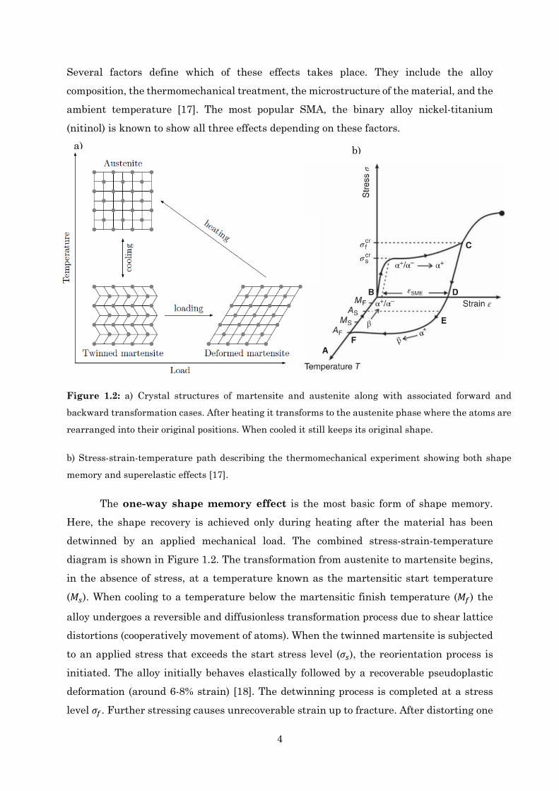
Several factors define which of these effects takes place. They include the alloy composition, the thermomechanical treatment, the microstructure of the material, and the ambient temperature [17]. The most popular SMA, the binary alloy nickel-titanium (nitinol) is known to show all three effects depending on these factors.
The one-way shape memory effect is the most basic form of shape memory. Here, the shape recovery is achieved only during heating after the material has been detwinned by an applied mechanical load. The combined stress-strain-temperature diagram is shown in Figure 1.2. The transformation from austenite to martensite begins, in the absence of stress, at a temperature known as the martensitic start temperature (𝑀𝑀𝑠𝑠). When cooling to a temperature below the martensitic finish temperature (𝑀𝑀𝑓𝑓) the
alloy undergoes a reversible and diffusionless transformation process due to shear lattice distortions (cooperatively movement of atoms). When the twinned martensite is subjected to an applied stress that exceeds the start stress level (𝜎𝜎𝑠𝑠), the reorientation process is initiated. The alloy initially behaves elastically followed by a recoverable pseudoplastic deformation (around 6-8% strain) [18]. The detwinning process is completed at a stress level 𝜎𝜎𝑓𝑓. Further stressing causes unrecoverable strain up to fracture. After distorting one
Figure 1.2: a) Crystal structures of martensite and austenite along with associated forward and
backward transformation cases. After heating it transforms to the austenite phase where the atoms are
rearranged into their original positions. When cooled it still keeps its original shape.
b) Stress-strain-temperature path describing the thermomechanical experiment showing both shape
memory and superelastic effects [17].
a) b)
5
can recover the original shape by heating above the austenite finish temperature (𝐴𝐴𝑓𝑓).
Therefore, residual strains are completely recovered as the low symmetric martensitic phase is transformed back to stable austenitic phase, thus contributing to the rearrangement of the alloy at an atomic scale. The deformed martensite is now transformed to the austenite which has the microscopic as well as the macroscopic configuration of the initial undeformed state.
The two-way shape memory effect is obtained by a special thermal treatment, consisting of a series of thermal cycles, during which high-temperature and low-temperature shapes are imposed on an SMA component [3]. Hence, one obtains an SMA which can remember both its low-temperature shape (martensite) and high-temperature shape (austenite). Two-way shape memory alloys switch from their low-temperature shape to their high-temperature shape, but their recoverable strain is usually about half of the corresponding one-way recoverable strain for the same material.
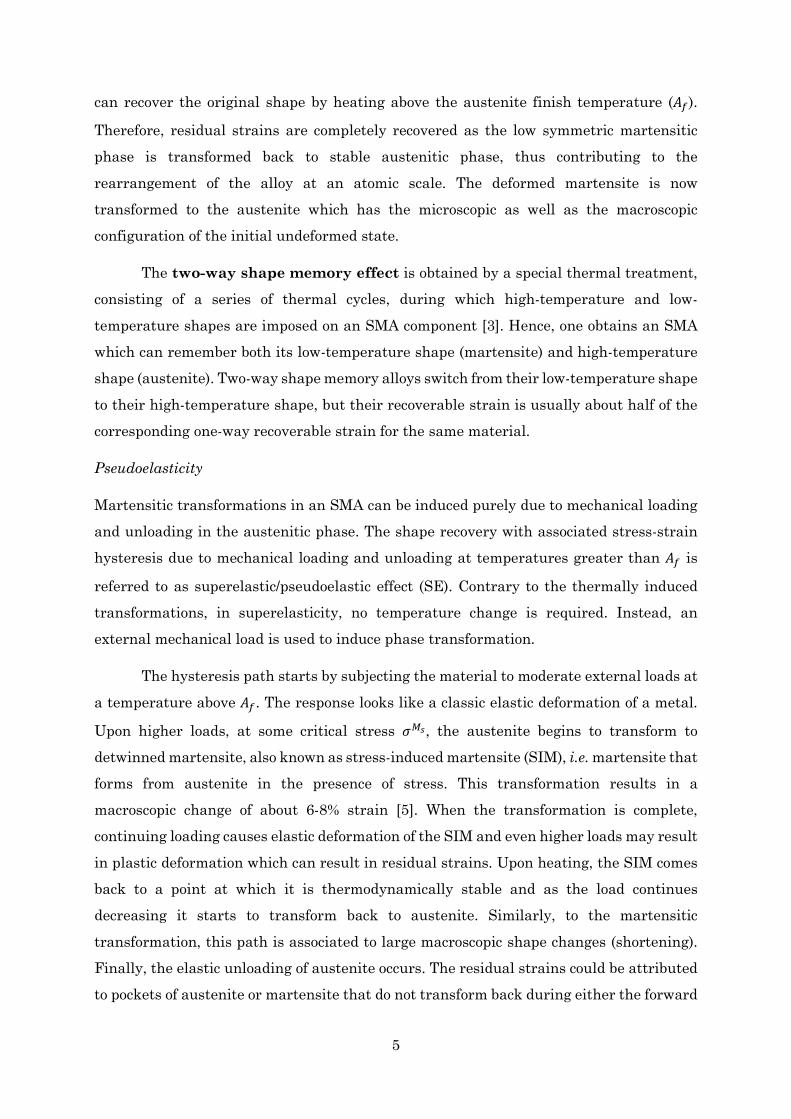
Pseudoelasticity
Martensitic transformations in an SMA can be induced purely due to mechanical loading and unloading in the austenitic phase. The shape recovery with associated stress-strain hysteresis due to mechanical loading and unloading at temperatures greater than 𝐴𝐴𝑓𝑓 is
referred to as superelastic/pseudoelastic effect (SE). Contrary to the thermally induced transformations, in superelasticity, no temperature change is required. Instead, an external mechanical load is used to induce phase transformation.
The hysteresis path starts by subjecting the material to moderate external loads at a temperature above 𝐴𝐴𝑓𝑓. The response looks like a classic elastic deformation of a metal.
Upon higher loads, at some critical stress 𝜎𝜎𝑀𝑀𝑠𝑠, the austenite begins to transform to detwinned martensite, also known as stress-induced martensite (SIM), i.e. martensite that forms from austenite in the presence of stress. This transformation results in a macroscopic change of about 6-8% strain [5]. When the transformation is complete, continuing loading causes elastic deformation of the SIM and even higher loads may result in plastic deformation which can result in residual strains. Upon heating, the SIM comes back to a point at which it is thermodynamically stable and as the load continues decreasing it starts to transform back to austenite. Similarly, to the martensitic transformation, this path is associated to large macroscopic shape changes (shortening). Finally, the elastic unloading of austenite occurs. The residual strains could be attributed to pockets of austenite or martensite that do not transform back during either the forward

6
or backward transformations. Figure 1.3 presents the stress-strain-temperature curve depicting pseudoelasticity of SMAs.
1.3 NiTi Based Alloys Figure 1.4 lists several alloys systems where the shape memory properties had been observed. The most popular among these is the NiTi, as most of these systems do not present favourable commercial applications. In fact, the potential practical uses and substantial attraction of this phenomenon only began in the 1960s, when the SME was first reported in a NiTi alloy [17]. This discovery took place at the US Naval Ordnance Laboratory (NOL, White Oak, Maryland) and hence NiTi based SMAs are often referred to as NitiNOL in its honour. Despite the high production costs and the high market prices for high-purity nickel and for high-purity titanium, the nitinol’s properties make this material ideal for a variety of applications. In reality, 90% of current commercial shape memory applications are based on binary NiTi [17] [19].
When the composition of NiTi is equiatomic (i.e. 50 at% of Ni and Ti), the alloy exhibits the maximum 𝐴𝐴𝑓𝑓 temperature (120 ºC). Decreasing the Ni atomic percentage
(at%) from the equiatomic composition does not change the transformation temperatures. If the composition of nickel is increased above 50 at%, the transformation temperature begins to decrease, with 𝐴𝐴𝑓𝑓 becoming as low as −40 ºC for 51 at% nickel. This variation in
Figure 1.3: Superelastic/pseudoelastic response of a SMA at three different temperatures [5].
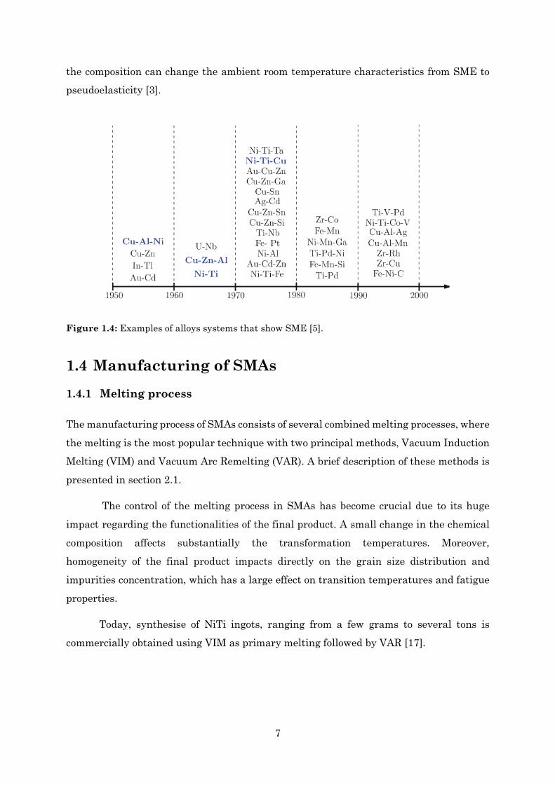
7
the composition can change the ambient room temperature characteristics from SME to pseudoelasticity [3].
1.4 Manufacturing of SMAs 1.4.1 Melting process
The manufacturing process of SMAs consists of several combined melting processes, where the melting is the most popular technique with two principal methods, Vacuum Induction Melting (VIM) and Vacuum Arc Remelting (VAR). A brief description of these methods is presented in section 2.1.
The control of the melting process in SMAs has become crucial due to its huge impact regarding the functionalities of the final product. A small change in the chemical composition affects substantially the transformation temperatures. Moreover, homogeneity of the final product impacts directly on the grain size distribution and impurities concentration, which has a large effect on transition temperatures and fatigue properties.
Today, synthesise of NiTi ingots, ranging from a few grams to several tons is commercially obtained using VIM as primary melting followed by VAR [17].
Figure 1.4: Examples of alloys systems that show SME [5].
8
1.4.2 Post-Treatments
At the industry level, the control of the melting process is not enough to obtain NiTi alloys with the desired structural and functional properties, especially for biomedical applications. Several post-treatments as hot working, cold working, machining, surface treatments, joining, and heat treatments are necessary in order to fulfil the requirements regarding the final properties of the material [20–21]. The nitinol phase diagram shown in Figure 1.5 clearly shows that temperatures can greatly influence the formation of various precipitates. It is known that ageing treatments affect the transformation sequence and the mechanical behaviour of the material [20]][22–23]. Annealed NiTi alloys at 850 ºC for 15 minutes show one step on both heating and cooling. When alloys exposed ageing at 400 ºC and 500 ºC for different times, the multistage transformation is seen [24]. Recent investigations have shown the influence of stress ageing process on transformation temperature. It was seen that martensitic transformation temperature of NiTi alloys increases with increasing the stress levels [23].
Once the melting process is completed, the ingot is usually forged, swaged, rolled, or extruded at high temperatures, mostly performed in successive steps with alternated annealing. These hot working steps reduce the size of the initial ingot, to establish the homogeneity and to adjust the grain size. Moreover, hot working offers the ability to obtain a suitable shape of the ingot: bars, composites or tubes. The process is performed under temperatures ranging from 800–950 ºC [17]. The next stage is a series of cold working processes with frequently alternated annealings in a range of temperatures from 500–800 ºC [17]. Final product shapes such as wire, tubing, and sheets can be achieved via cold working. The average ductility of NiTi allows 30–50% of cold work [25]. NiTi wires, the most widely available form of this material, are produced via drawing.
Figure 1.5: Phase diagram of NiTi [5].
9
1.5 Design of SMA actuators To design an SMA component it is imperative to understand which basic requirements are important for its final application. Factors like chemical composition, shape, operating temperature, loading and thermomechanical conditions can significantly affect the performance of the component. Regarding Table 1.2, one can see that NiTi SMA is a good choice for actuators that provide significant strokes and forces. Also, SMA actuators have the ability to react directly to the surrounding stimulus, and they prove to be bio-compatible and have high wear resistance [8].
Despite the promising characteristics, there are several limitations to overcome, which include moderately small strains, slow actuation response, low accuracy, low energy efficiency, and low controllability, due to hysteresis, nonlinearities, parameter uncertainties, and difficulties in measuring state variables such as temperature [17].
Shape setting plays an important role in terms of actuation performance. Straight wires are the most popular form of shape memory alloy. Nonetheless, other shapes such as coil springs, torsion springs, cantilever strips, and torsion tubes are often chosen, depending on the actuation requirements. Commonly, to address the problem of small strains, engineers train NiTi wires as coil springs actuators, since this shape makes possible larger displacements. Generally, induced mechanical stress makes the spring expand, while the thermal activation, leads to the contraction of the coil structure. Joule heating effect is mostly used as an effective and simple way for actuating SMA wires and springs, where current flows directly throughout the SMA component. Figure 1.6 depicts a typical SMA coil actuation cycle [26].
Actuator type Stress
(MPa) Strain (%)
Efficiency
(%)
Bandwidth
(Hz)
Work/Volume
(J/cm3)
Power/Volume
(W/cm3)
NiTi SMA 200 10 3 3 10 30
Piezoceramic 35 0.2 50 5000 0.035 175
Single crystal piezoelectric
300 1.7 90 5800 2.25 15000
Human Muscle 0.007-0.8 1-100 35 2-173 0.035 0.35
Hydraulic 20 50 80 4 5 20
Pneumatic 0.7 50 90 20 0.175 3.5
Table 1.2: Comparison of commercially available types of actuators [8].
10
1.6 Overview of SMA Applications Since the discovery of the shape memory effect, much research efforts have been devoted regarding SMAs performance in several applications. Despite the limitations, numerous studies revealed the potentials for SMAs from actuation to sensing and control. Due to their unique thermomechanical characteristics, their compactness and lightness, engineers have been implementing SMAs in real-world applications, ranging from biomedical, automotive aerospace, and robotics areas.
1.6.1 Biomedical Applications
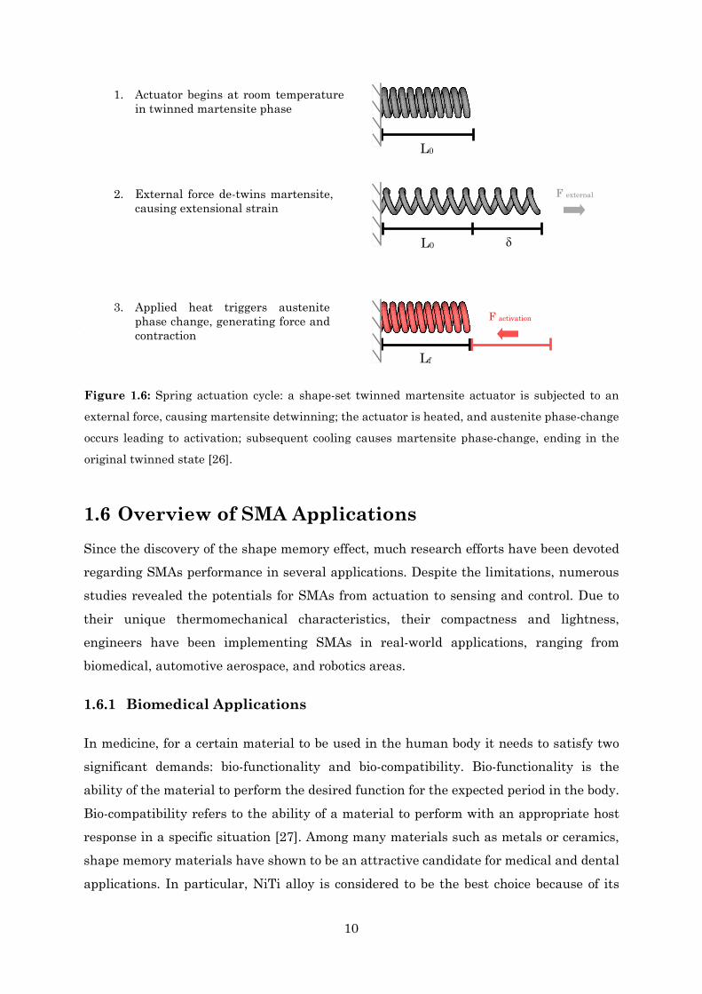
In medicine, for a certain material to be used in the human body it needs to satisfy two significant demands: bio-functionality and bio-compatibility. Bio-functionality is the ability of the material to perform the desired function for the expected period in the body. Bio-compatibility refers to the ability of a material to perform with an appropriate host response in a specific situation [27]. Among many materials such as metals or ceramics, shape memory materials have shown to be an attractive candidate for medical and dental applications. In particular, NiTi alloy is considered to be the best choice because of its
Figure 1.6: Spring actuation cycle: a shape-set twinned martensite actuator is subjected to an
external force, causing martensite detwinning; the actuator is heated, and austenite phase-change
occurs leading to activation; subsequent cooling causes martensite phase-change, ending in the
original twinned state [26].
1. Actuator begins at room temperature in twinned martensite phase
2. External force de-twins martensite, causing extensional strain
3. Applied heat triggers austenite phase change, generating force and contraction
F activation
F external
L0
L0
Lf
11
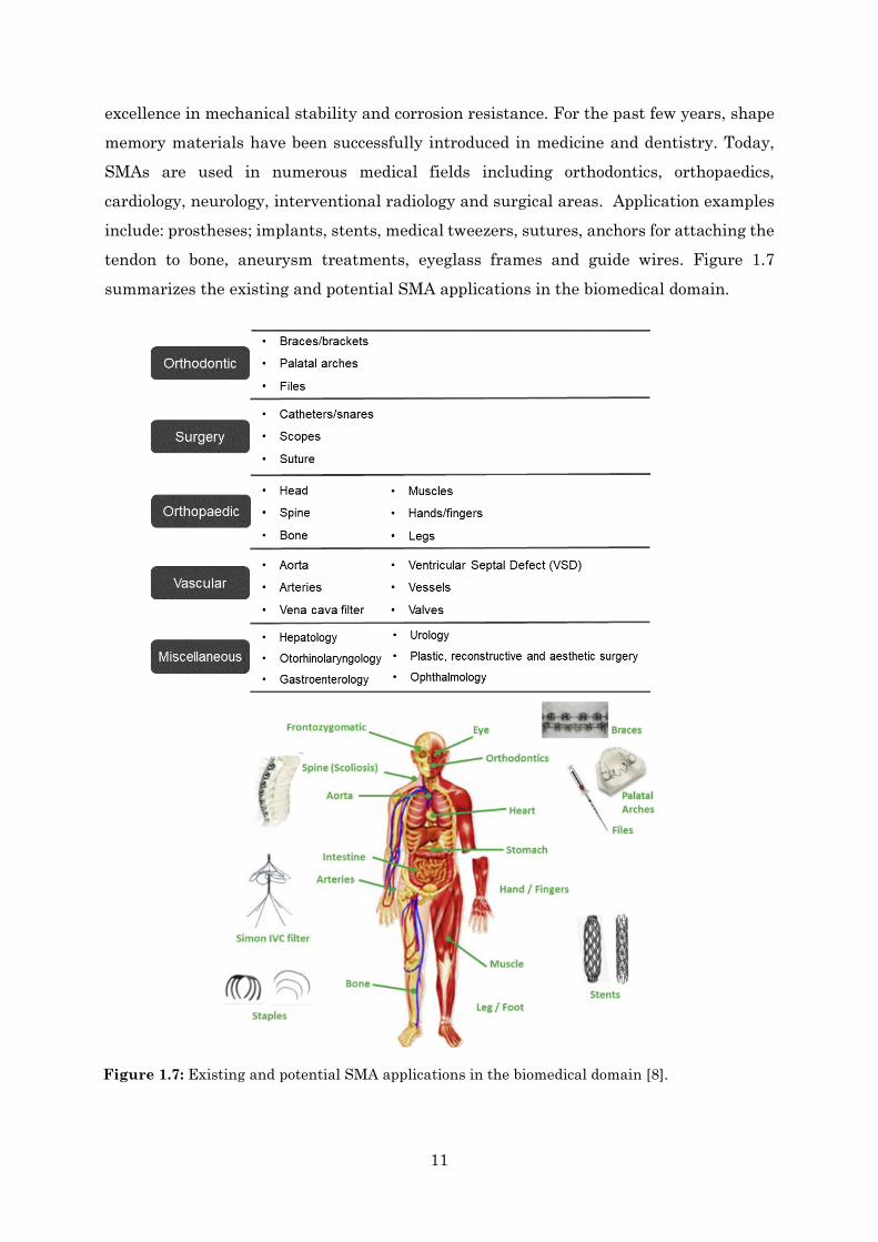
excellence in mechanical stability and corrosion resistance. For the past few years, shape memory materials have been successfully introduced in medicine and dentistry. Today, SMAs are used in numerous medical fields including orthodontics, orthopaedics, cardiology, neurology, interventional radiology and surgical areas. Application examples include: prostheses; implants, stents, medical tweezers, sutures, anchors for attaching the tendon to bone, aneurysm treatments, eyeglass frames and guide wires. Figure 1.7 summarizes the existing and potential SMA applications in the biomedical domain.
Figure 1.7: Existing and potential SMA applications in the biomedical domain [8].
12
1.6.2 Aerospace Applications
One of the early applications of SMAs regarding aerospace domain was the NiTiFe
hydraulic tubing coupling used on the F-14 fighter jets in 1971 [8]. Since then, engineers
have continued to exploit the properties of SMAs in solving engineering problems in the aerospace industry, where high dynamic loads and geometric space constraints are significant.
In the 1990s, two fixed-wing programs, Smart Wing and the Smart Aircraft and Marine Propulsion System demonstration (SAMPSON), revealed to be an important milestone in the development and application of smart materials and structures technologies to perform active control.
The objective of the Smart Wing program was to develop smart materials that would provide improved aerodynamic and aeroelastic. It consisted of two phases in which the first one involves the development of an SMA based, hingeless, smoothly contoured trailing edge and actively variable wing twists with SMA torque tubes [28]. The SMA wire tendons were used to actuate hingeless ailerons while an SMA torque tube was used to initiate spanwise wing twisting of a scaled-down F-18. This essentially leads to the efforts for circumvention of the bottlenecks of actuation bandwidths and improvements of the actuation range, caused by the actuation via shape-recovery. This work was a collaboration between the Defense Advanced Research Projects Agency (DARPA), Air Force Research Lab (AFRL) and Northrop Grumman.
The usefulness of active materials in tailoring propulsion systems was demonstrated on an F-15 engine inlet through the SAMPSON program [29]. A total force of approximately 26 700 N was achieved using SMA bundles containing 34 wires/rods, as it rotated the inlet cowl 9 º. This work was performed as part of a DARPA contract to Boeing and monitored by the NASA Langley Research Center and the Office of Naval Research [28].
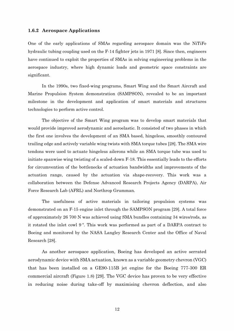
As another aerospace application, Boeing has developed an active serrated aerodynamic device with SMA actuation, known as a variable geometry chevron (VGC) that has been installed on a GE90-115B jet engine for the Boeing 777-300 ER commercial aircraft (Figure 1.8) [29]. The VGC device has proven to be very effective in reducing noise during take-off by maximising chevron deflection, and also
13
increasing the cruise efficiency by minimising chevron deflection during the remainder of the flight.
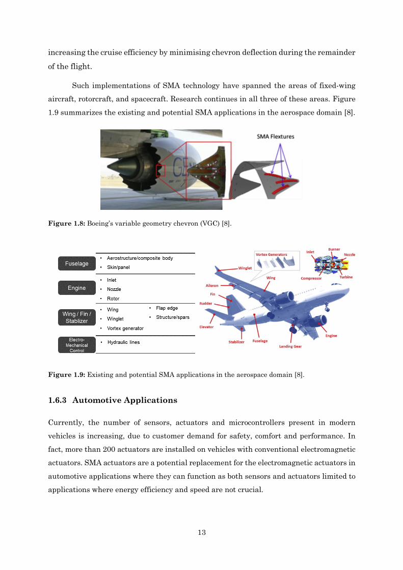
Such implementations of SMA technology have spanned the areas of fixed-wing aircraft, rotorcraft, and spacecraft. Research continues in all three of these areas. Figure 1.9 summarizes the existing and potential SMA applications in the aerospace domain [8].
1.6.3 Automotive Applications
Currently, the number of sensors, actuators and microcontrollers present in modern vehicles is increasing, due to customer demand for safety, comfort and performance. In fact, more than 200 actuators are installed on vehicles with conventional electromagnetic actuators. SMA actuators are a potential replacement for the electromagnetic actuators in automotive applications where they can function as both sensors and actuators limited to applications where energy efficiency and speed are not crucial.
Figure 1.8: Boeing’s variable geometry chevron (VGC) [8].
Figure 1.9: Existing and potential SMA applications in the aerospace domain [8].
14
One of the earliest commercial SMA actuators for automotive application is the thermally responsive pressure control valve embedded in Mercedes-Benz automatic transmissions for smooth gear shifting, which was first introduced in 1989 [30]. This valve's function is shown schematically in Figure 1.10. Later, Alfmeier Präzision AG has successfully mass-produced SMA pneumatic valves for lumbar support in car seats for Daimler Mercedes-Benz, and today these devices are used by most automotive manufacturers such as BMW, General Motors (GM), Hyundai, Ford, Porsche and Volkswagen (VW) [8]. GM seventh-generation Chevrolet Corvette was announced to be the first GM vehicle with SMA actuator to actuate the hatch vent for easier closing of the trunk lid. Under the Fiat group, Centro Ricerche Fiat (CRF) has also been intensively involved in SMA applications and numerous patents have been issued by them, such as the electrically actuated antiglare rear-view (EAGLE) mirror, headlamp actuators, fuel filling lid actuator, and locking mechanism [30].
Nowadays most of the applications are electric and active thermal actuators. Thermal actuators respond to changes in temperature by changing their shape and generating a force. Electrical actuators are devices where the stimulus is any voltage
applied to it. If electrically heated above 𝐴𝐴𝑠𝑠, such as by passing current through a wire or spring, nitinol shape memory elements can provide interesting advantages over motors and solenoids due to their small size and noiseless operation.
In general, there are three categories of automotive actuators: low power actuators for comfort and bodywork functions; high power vehicle control actuators; and high-frequency engine control actuators [30]. SMA actuators are most suitable for the first category and feasible for the second category. Figure 1.11 and Figure 1.12 schematically shows the areas in a car where thermal and electrical shape memory actuators have been suggested [31]. However, few have actually been implemented or seem technically and economically feasible because of the limited range of transformation temperatures. As shown in Figure 1.13, the transformation temperature of nitinol ranges from -50 °C to +110 °C, which fulfils the operating temperature requirement in the passenger room (i.e. -40 °C to +85 °C), but not entirely in the engine room (i.e. -40 °C to +125 °C) [8][31]. SMAs satisfy almost all the requirements above, particularly for applications in passenger room and locations with moderate temperatures. Furthermore, with proper design, system control and functionality, SMAs potentially could fulfil all the requirements.
15
Figure 1.11: Potential applications of shape memory thermal actuators in automobiles: (1)
radiator shutler; (2) fan clutch; (3) fuel management; (4) climate control; (5) engine control; (6)
brake ventilation; (7) transmission control/rattling noise reduction; (8) suspension adjustment
[31].
Figure 1.10: Schematic function of a thermal valve [31].
Figure 1.12: Potential applications for electrical shape memory actuators in automobiles: (1)
foglamp louvre; (2) engine hood lock; (3) retractable headlight; (4) fuel management; (5) engine
control; (6) transmission control; (7) climate control; (8) wiper pressure control; (9) rear-view
mirror adjustment; (10) seat·belt adjustment; (II) central locking system; (12) shock absorber
adjustment; (13) filler inlet lock; (14) trunk lock [31].
16
Figure 1.13: Operating temperature range for automobiles applications and the transformation
temperatures for selected commercially available and developed SMAs [8].
1.6.4 Robotic Applications
In addition to the transportation and medical industries, there are many other applications that incorporate SMAs. Due to the biocompatibility of SMAs and the high performances of the actuators, there are a lot of possibilities to develop improved and innovative products applied successfully in robotics, especially in systems like micro-actuators and artificial muscles [8] [12] [31–32].
Considerable work has been done in developing grippers for robotic manipulation. In particular, a great effort has been addressed to the fabrication of grippers on the microscopic scale (i.e. about 600 µm displacement) that can be actuated wirelessly with an RF magnetic field. The frequency-sensitive LC resonant circuit is heated when an RF magnetic field passes through it and then transfers the heat energy to the SMA actuator for activation. The opportunity to control multiple selections of micro-SMA actuators is possible by applying different resonant frequencies, either selectively or simultaneously to the actuators [8] [34].
SMAs have been successfully integrated into prosthetic devices to enhance the quality of life for amputees. Prototypes such as robotic finger and shoulder joint that emulate human skeletal structures are actuated with SMA artificial muscles. It is shown
17
that these systems can exhibit relatively large motions and their use is possible for artificial limbs [8] [26–27].
Many robotics researchers are more interested in developing biomimetics and humanoid robots. These robots are useful in solving problems that are challenging for humans, by providing pertinent information from underwater, space, air and land. A biped mountable robotic baby head, that could be used for children education, entertainment, and household activities was developed using a combination of biometal fiber and SMA wires. Humanlike facial expressions were demonstrated by combining the SMAs with the elastomeric skin, mechanical components, and microcontroller-based driving electronics [36].
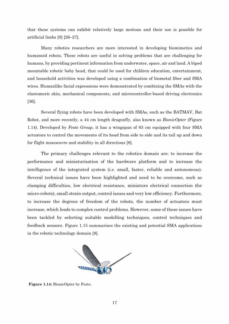
Several flying robots have been developed with SMAs, such as the BATMAV, Bat Robot, and more recently, a 44 cm length dragonfly, also known as BionicOpter (Figure 1.14). Developed by Festo Group, it has a wingspan of 63 cm equipped with four SMA actuators to control the movements of its head from side to side and its tail up and down for flight manoeuvre and stability in all directions [8].
The primary challenges relevant to the robotics domain are: to increase the performance and miniaturisation of the hardware platform and to increase the intelligence of the integrated system (i.e. small, faster, reliable and autonomous). Several technical issues have been highlighted and need to be overcome, such as clamping difficulties, low electrical resistance, miniature electrical connection (for micro-robots), small strain output, control issues and very low efficiency. Furthermore, to increase the degrees of freedom of the robots, the number of actuators must increase, which leads to complex control problems. However, some of these issues have been tackled by selecting suitable modelling techniques, control techniques and feedback sensors. Figure 1.15 summarizes the existing and potential SMA applications
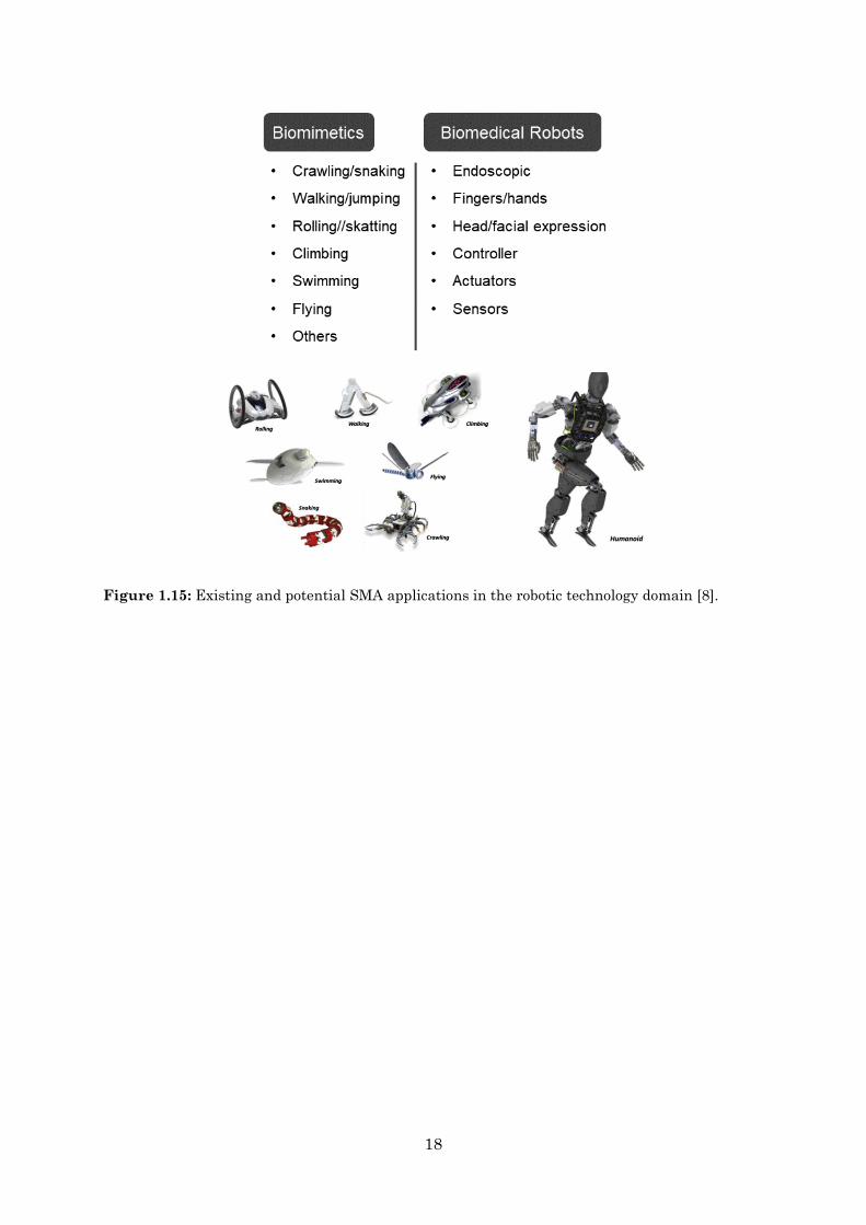
in the robotic technology domain [8].
Figure 1.14: BionicOpter by Festo.
18
Figure 1.15: Existing and potential SMA applications in the robotic technology domain [8].
19
1.7 CeNTI and Project Objectives In Portugal, one of the Technological Transfer Centers working with smart
materials is Centre for Nanotechnology and Smart Materials (CeNTI), highly recognized for its expertise in materials functionalization by using integrated electronics, sensors, coatings, as well as transferring knowledge from physics, chemistry, nanotechnology, and others to real world products. This work was part of an internship program between CeNTI and Faculdade de Ciências da Universidade do Porto.
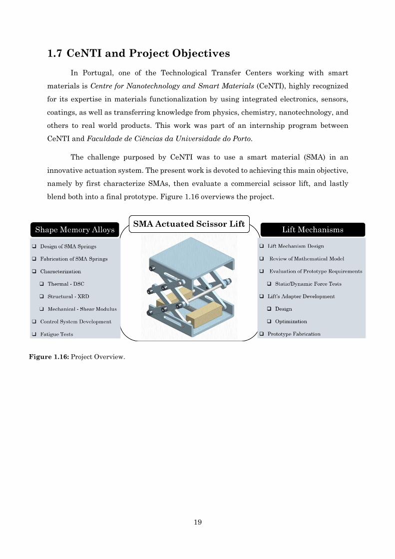
The challenge purposed by CeNTI was to use a smart material (SMA) in an innovative actuation system. The present work is devoted to achieving this main objective, namely by first characterize SMAs, then evaluate a commercial scissor lift, and lastly blend both into a final prototype. Figure 1.16 overviews the project.
Figure 1.16: Project Overview.

20
21
Chapter 2
2. Design of an SMA Actuator The primary objective of this research is to demonstrate the use of a smart material in an innovative actuation system. As explained before, advantages such as high force-to-weight ratio and large displacement capability, make SMAs preferable over other smart materials. Concerning the mechanical actuation system, it was intended for the prototype to act as a lift, i.e. to perform mechanical work on lifting a weight.
2.1 Lift Mechanisms Design The demands by CeNTI for the application was that the mechanical prototype should be small, lightweight and compact. The weight should be lifted only vertically (without horizontal translation movement). Its actuation should be made by means of a spring configuration as it provides more strength when compared with wires. Several ideas have emerged, and so a preliminary evaluation of the advantages and disadvantages of each mechanism was essential. Three different lift mechanisms were suggested:
• Lever
• Rack and Pinion
• Scissor Lift
2.1.1 Lever
A lever is a simple machine consisting in a solid bar (beam) that rests on a pivot point (fulcrum). It can be used to exert a large force over a small distance at one end of the lever by exerting a small force over a greater distance at the other end. It is probably one of the oldest mechanisms to lift heavy objects. The object pushed by the lever is called the load,
22
while the force applied to the lever is called the effort. A seesaw is a great example of a lever. In physics the seesaw is an academic example of rotation equilibrium, which states that the angular acceleration about any axis must be zero, i.e. when the algebraic sum of the torques is zero:
𝑟𝑟𝑖𝑖 × 𝐹𝑖𝑖 = 0 (2.1)
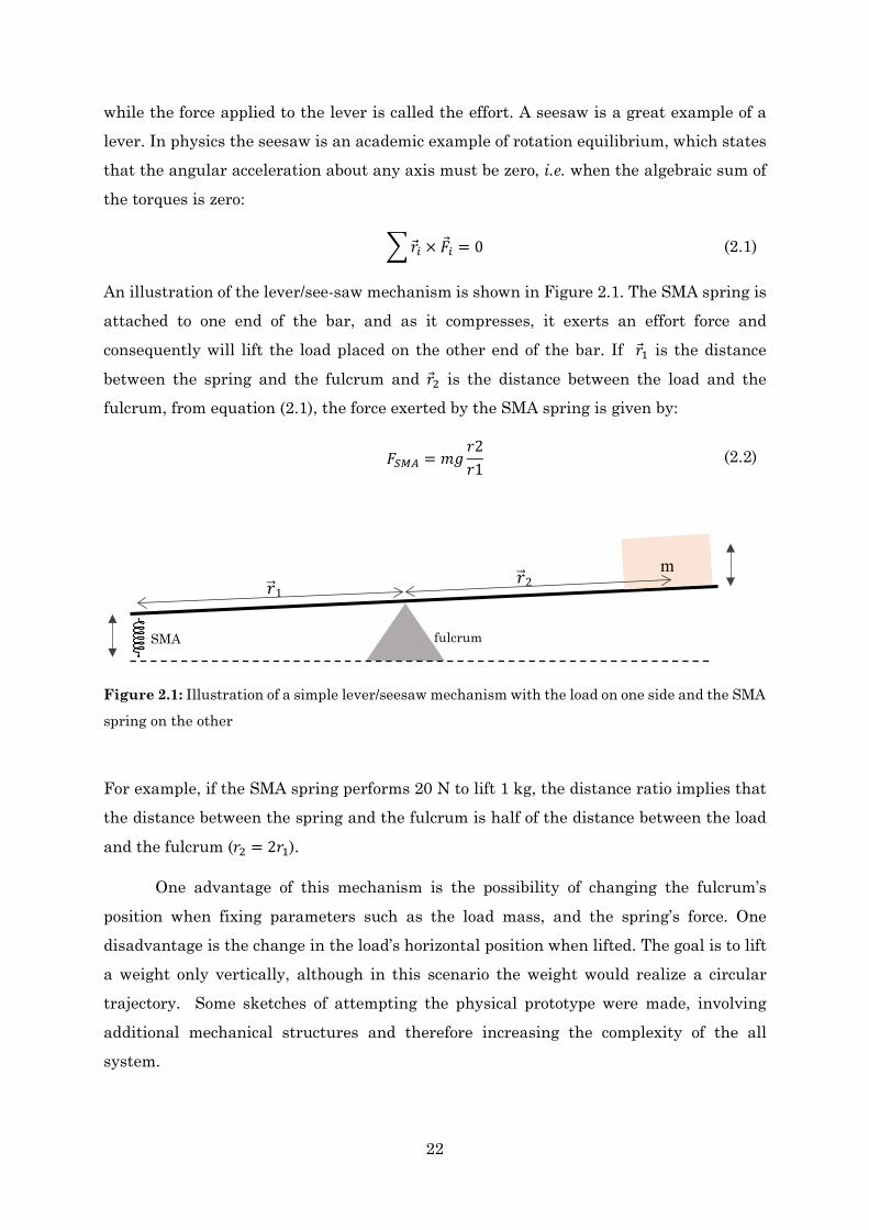
An illustration of the lever/see-saw mechanism is shown in Figure 2.1. The SMA spring is attached to one end of the bar, and as it compresses, it exerts an effort force and consequently will lift the load placed on the other end of the bar. If 𝑟𝑟1 is the distance between the spring and the fulcrum and 𝑟𝑟2 is the distance between the load and the fulcrum, from equation (2.1), the force exerted by the SMA spring is given by:
𝐹𝐹𝑆𝑆𝑀𝑀𝑆𝑆 = 𝑚𝑚𝑚𝑚𝑟𝑟2𝑟𝑟1
(2.2)
For example, if the SMA spring performs 20 N to lift 1 kg, the distance ratio implies that the distance between the spring and the fulcrum is half of the distance between the load
and the fulcrum (𝑟𝑟2 = 2𝑟𝑟1).
One advantage of this mechanism is the possibility of changing the fulcrum’s position when fixing parameters such as the load mass, and the spring’s force. One disadvantage is the change in the load’s horizontal position when lifted. The goal is to lift a weight only vertically, although in this scenario the weight would realize a circular trajectory. Some sketches of attempting the physical prototype were made, involving additional mechanical structures and therefore increasing the complexity of the all system.
SMA fulcrum
m 𝑟𝑟 1 𝑟𝑟 2
Figure 2.1: Illustration of a simple lever/seesaw mechanism with the load on one side and the SMA
spring on the other

23
2.1.2 Rack and Pinion
Another idea was to use gears to transmit motion over a small distance, for example, a rack and pinion mechanism. Figure 2.2 illustrates the 3D draft of the mechanism. The spur gear is the pinion and the straight gear is the rack. The rack has teeth cut into it and they mesh the teeth of the pinion. The basic operating principle is to convert linear motion into rotary motion, or vice-versa. The apparatus consists of a pair of pinions engaged in vertical and horizontal racks. The SMA spring actuates on the horizontal rack, which rotates the smaller pinion. The circular movement of the small pinion rotates the big pinion, which consequently moves the vertical rack.
The rack and pinion mechanism provides a compact and easy way to convert rotary motion into linear motion. Thanks to the big spur gear, a small displacement of the horizontal rack can provide greater vertical displacement of the vertical rack. If for example, the radius of the big pinion is twice the radius of the smaller pinion, the vertical displacement would be twice the horizontal displacement. However, the mechanism needs to be assembled into a compact prototype and no valuable idea was projected.
Figure 2.2: Draft of the rack and pinion lift mechanism actuated by an SMA spring.
SMA SMA
24
2.1.3 Scissor Lift
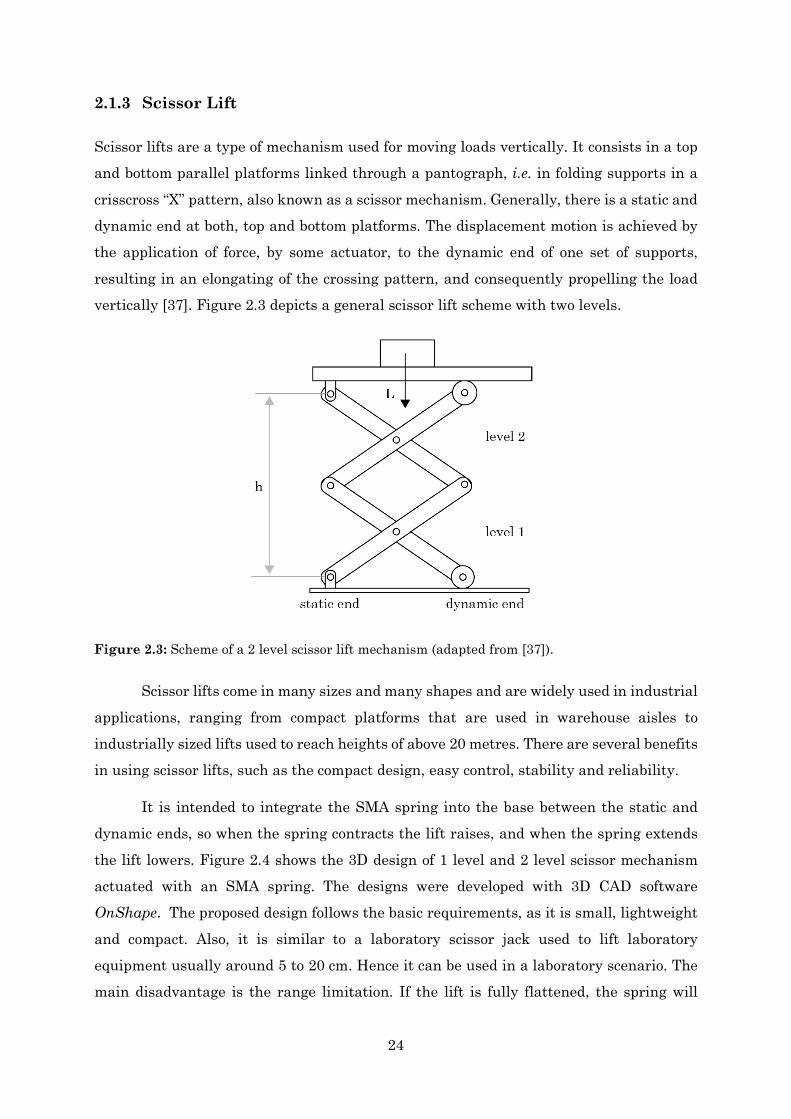
Scissor lifts are a type of mechanism used for moving loads vertically. It consists in a top and bottom parallel platforms linked through a pantograph, i.e. in folding supports in a crisscross “X” pattern, also known as a scissor mechanism. Generally, there is a static and dynamic end at both, top and bottom platforms. The displacement motion is achieved by the application of force, by some actuator, to the dynamic end of one set of supports, resulting in an elongating of the crossing pattern, and consequently propelling the load vertically [37]. Figure 2.3 depicts a general scissor lift scheme with two levels.
Scissor lifts come in many sizes and many shapes and are widely used in industrial applications, ranging from compact platforms that are used in warehouse aisles to industrially sized lifts used to reach heights of above 20 metres. There are several benefits in using scissor lifts, such as the compact design, easy control, stability and reliability.
It is intended to integrate the SMA spring into the base between the static and dynamic ends, so when the spring contracts the lift raises, and when the spring extends the lift lowers. Figure 2.4 shows the 3D design of 1 level and 2 level scissor mechanism actuated with an SMA spring. The designs were developed with 3D CAD software OnShape. The proposed design follows the basic requirements, as it is small, lightweight and compact. Also, it is similar to a laboratory scissor jack used to lift laboratory equipment usually around 5 to 20 cm. Hence it can be used in a laboratory scenario. The main disadvantage is the range limitation. If the lift is fully flattened, the spring will
Figure 2.3: Scheme of a 2 level scissor lift mechanism (adapted from [37]).

25
require very large forces to operate, and so it is necessary the use of stroke limiters/hard stops.
After a preliminary evaluation of all the three possible mechanisms, the scissor lift was the more appealing in terms of design, manufacturing and operation. In the next section a model that expresses the force output of a scissor lift is presented. It is also described the geometry of the intended prototype and the proposed adapter which assembles the lift together with the SMA spring.
2.2 Scissor Lift Design 2.2.1 Force Model
The equation for the output force of the actuator located in the base of a 2-level scissor lift was obtained by Spackman in 1982 [38] and is given by:
𝐹𝐹 =
2𝑚𝑚 𝑚𝑚 + 𝑀𝑀𝐿𝐿2
tan(𝜃𝜃) (2.3)
where m is the mass of the load, ML is the lift’s mass and θ is the angle between the scissor arm and the horizontal plane. Notice that the weight of the scissor lift is modelled by placing half its weight at the top, i.e. by adding half of the weight of the scissor lift to the load. For the purposes of this thesis, the model will not be derived here, as it is
Figure 2.4: Design of a 1 level and 2 level scissor lift actuated with an SMA spring.
26
demonstrated in more detail by Spackman. Instead, the equation 2.3 was assumed as a theoretical model, and it was used to predict the force which the SMA spring will be subjected to.
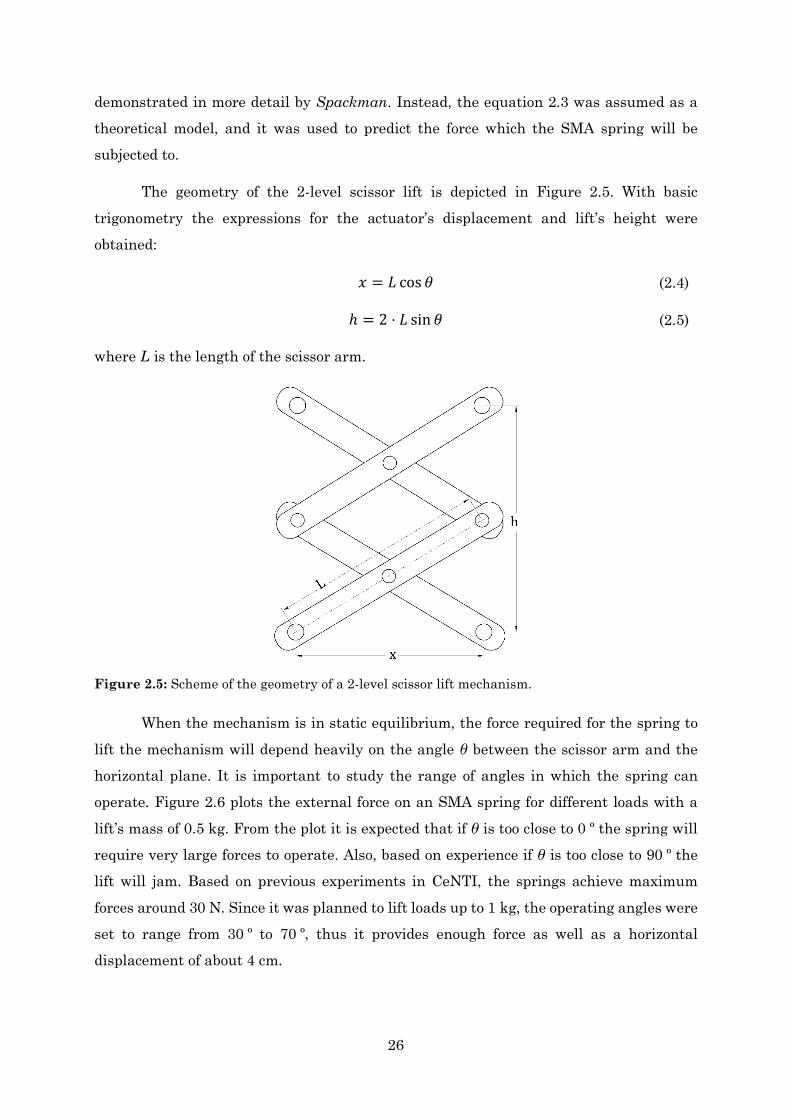
The geometry of the 2-level scissor lift is depicted in Figure 2.5. With basic trigonometry the expressions for the actuator’s displacement and lift’s height were obtained:
𝑥𝑥 = 𝐿𝐿 cos 𝜃𝜃 (2.4)
ℎ = 2 ⋅ 𝐿𝐿 sin 𝜃𝜃 (2.5)
where L is the length of the scissor arm.
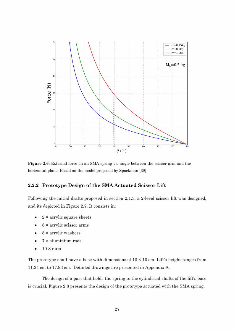
When the mechanism is in static equilibrium, the force required for the spring to lift the mechanism will depend heavily on the angle θ between the scissor arm and the horizontal plane. It is important to study the range of angles in which the spring can operate. Figure 2.6 plots the external force on an SMA spring for different loads with a lift’s mass of 0.5 kg. From the plot it is expected that if θ is too close to 0 º the spring will require very large forces to operate. Also, based on experience if θ is too close to 90 º the lift will jam. Based on previous experiments in CeNTI, the springs achieve maximum forces around 30 N. Since it was planned to lift loads up to 1 kg, the operating angles were set to range from 30 º to 70 º, thus it provides enough force as well as a horizontal displacement of about 4 cm.
Figure 2.5: Scheme of the geometry of a 2-level scissor lift mechanism.
27
2.2.2 Prototype Design of the SMA Actuated Scissor Lift
Following the initial drafts proposed in section 2.1.3, a 2-level scissor lift was designed, and its depicted in Figure 2.7. It consists in:
• 2 × acrylic square sheets
• 8 × acrylic scissor arms
• 8 × acrylic washers
• 7 × aluminium rods
• 10 × nuts
The prototype shall have a base with dimensions of 10 × 10 cm. Lift’s height ranges from 11.24 cm to 17.93 cm. Detailed drawings are presented in Appendix A.
The design of a part that holds the spring to the cylindrical shafts of the lift’s base is crucial. Figure 2.8 presents the design of the prototype actuated with the SMA spring.
ML=0.5 kg
Figure 2.6: External force on an SMA spring vs. angle between the scissor arm and the
horizontal plane. Based on the model proposed by Spackman [38].

28
The mechanical adapter shall be obtained through 3D printing at CeNTI facilities. The manufacturing process of the adapter is presented in detail in section 6.1.1.
Figure 2.7: Isometric and side view of the Scissor Lift Prototype designed in OnShape.
Figure 2.8: 3D CAD model of the SMA Actuated Scissor Lift.
29
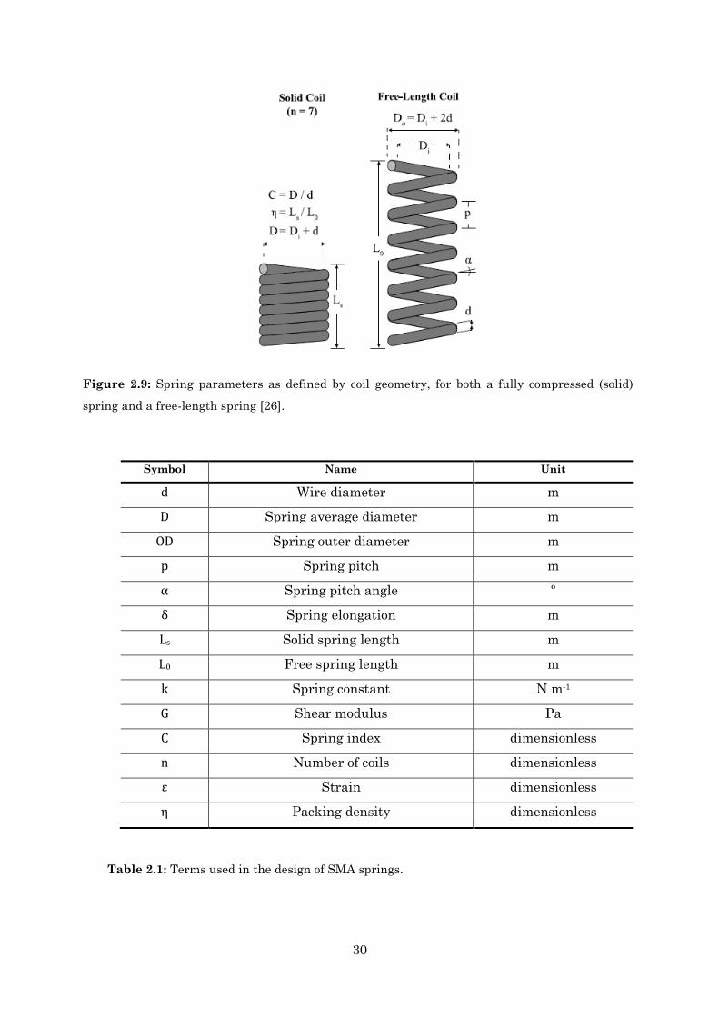
2.3 Design of SMA springs 2.3.1 Geometry and Force Modelling of NiTi springs
SMA spring actuators can be fabricated by shape setting wires. The experimental procedure is described in Chapter 3. When set as tightly packed springs, the shape recovery characteristics of SMA provide greater forces. Hence, the spring structure is well suited for the scissor lift actuation.
The force F generated by an SMA spring actuator follows Hooke’s law, and can be expressed by a given set of geometric parameters, presented in Figure 2.9 :
𝐹𝐹 = 𝑘𝑘𝑘𝑘 =
𝐺𝐺𝑑𝑑4
8𝐷𝐷3𝑛𝑛 𝑘𝑘 (2.6)
where d is the wire diameter, D is the spring diameter (as measured by the midpoint between inner and outer diameters), n is the number of spring coils, L0 is the free spring length, which is the total length of a fully-activated (i.e. austenite) actuator when unloaded, δ is the spring elongation, and G is the shear modulus [5], [26], [39].
For an easy reference, terms used in the design of SMA springs can be found in Table 2.1. A set of significant design equations used for springs are listed below:
𝑂𝑂𝐷𝐷 = 𝐷𝐷 + 𝑑𝑑 (2.7)
𝐶𝐶 =
𝐷𝐷𝑑𝑑
(2.8)
𝑘𝑘 =
𝐺𝐺𝑑𝑑4
8𝐷𝐷3𝑛𝑛 (2.9)
𝜂𝜂 =
𝑑𝑑𝑝𝑝
=𝐿𝐿𝑠𝑠𝐿𝐿0
=𝑛𝑛𝑑𝑑𝐿𝐿0
(2.10)
𝜖𝜖 =
𝑘𝑘𝐿𝐿0
(2.11)
30
Symbol Name Unit
d Wire diameter m
D Spring average diameter m
OD Spring outer diameter m
p Spring pitch m
α Spring pitch angle º
δ Spring elongation m
Ls Solid spring length m
L0 Free spring length m
k Spring constant N m-1
G Shear modulus Pa
C Spring index dimensionless
n Number of coils dimensionless
ε Strain dimensionless
η Packing density dimensionless
Table 2.1: Terms used in the design of SMA springs.
Figure 2.9: Spring parameters as defined by coil geometry, for both a fully compressed (solid)
spring and a free-length spring [26].
31
The maximum spring elongation 𝑘𝑘𝑀𝑀 due to martensite detwinning is given by [17]:
𝑘𝑘𝑀𝑀 =
𝜋𝜋𝑛𝑛𝐷𝐷2
𝑑𝑑√32𝜀𝜀𝑀𝑀 (2.12)
where 𝜀𝜀𝑀𝑀 is the maximum residual strain. Finally, substituting eq. (2.12) into eq. (2.6)
the maximum force for an SMA spring becomes:
𝐹𝐹 =
𝜋𝜋𝐺𝐺𝑑𝑑3
𝐷𝐷√316
𝜀𝜀𝑀𝑀 (2.13)
With eq. (2.13) one can design actuators to meet specific performance requirements, which may include force targets, size limitations, manufacturing limitations, or desired lengths or extensional strains. To get a prediction regarding the forces and displacements provided with different SMA spring characteristics, a spreadsheet was created based on the previous equations. Inputs such as the activation temperature, the wire diameter, the spring outside diameter, the number of coils, the shear modulus and others allow calculating force, displacement, maximum spring length elongation, etc. The spreadsheet is depicted in Appendix B.

32
33
Chapter 3
3. Experimental Methodology of NiTi SMA components
3.1 Manufacturing Process of NiTi SMAs When manufacturing an SMA component there is a combination of different and individually selected processes one can choose, depending on the desired shape, the desired properties, and the desired application. The NiTi alloy is an equiatomic intermetallic compound and a tiny composition shift from stoichiometry greatly affects the characteristics of the alloy. It is well known that the transformation temperature is extremely sensitive to composition. One per cent shift in Ni content results in a 100 K change in the 𝑀𝑀𝑠𝑠 or 𝐴𝐴𝑓𝑓 temperatures [4]. It is crucial to have an understanding on the
manufacturing and post treatment techniques especially as many of these processes greatly influence the performance of a SMA component [10–11][39–43].
Not only chemical composition affects substantially the structural and functional properties of NiTi alloys. In addition, homogeneity of the final product impacts directly in the microstructure (grain size distribution and impurities concentration). The melting and alloying procedures at high-temperatures strongly increase the impurity content. Since molten Ti is very reactive to carbon and oxygen, nitinol always must be produced from elemental nickel and titanium by melting in high vacuum or an inert gas atmosphere.
The primary manufacturing techniques can be classified as casting or powder metallurgy. Casting is the most popular with two principal methods: Vacuum Induction Melting (VIM) and Vacuum Arc Remelting (VAR). Usually, melting methods are followed by conventional hot and cold forming procedures and machining to the final shape.
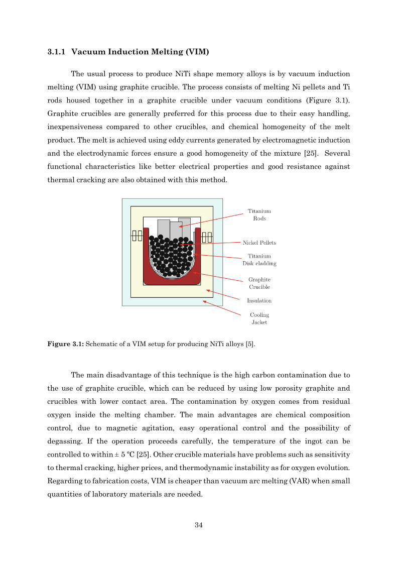
34
3.1.1 Vacuum Induction Melting (VIM)
The usual process to produce NiTi shape memory alloys is by vacuum induction melting (VIM) using graphite crucible. The process consists of melting Ni pellets and Ti rods housed together in a graphite crucible under vacuum conditions (Figure 3.1). Graphite crucibles are generally preferred for this process due to their easy handling, inexpensiveness compared to other crucibles, and chemical homogeneity of the melt product. The melt is achieved using eddy currents generated by electromagnetic induction and the electrodynamic forces ensure a good homogeneity of the mixture [25]. Several functional characteristics like better electrical properties and good resistance against thermal cracking are also obtained with this method.
The main disadvantage of this technique is the high carbon contamination due to the use of graphite crucible, which can be reduced by using low porosity graphite and crucibles with lower contact area. The contamination by oxygen comes from residual oxygen inside the melting chamber. The main advantages are chemical composition control, due to magnetic agitation, easy operational control and the possibility of degassing. If the operation proceeds carefully, the temperature of the ingot can be controlled to within ± 5 ºC [25]. Other crucible materials have problems such as sensitivity to thermal cracking, higher prices, and thermodynamic instability as for oxygen evolution. Regarding to fabrication costs, VIM is cheaper than vacuum arc melting (VAR) when small quantities of laboratory materials are needed.
Figure 3.1: Schematic of a VIM setup for producing NiTi alloys [5].
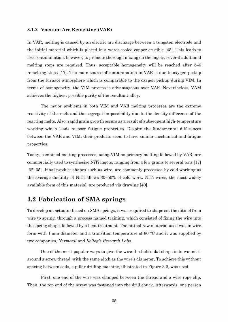
35
3.1.2 Vacuum Arc Remelting (VAR)
In VAR, melting is caused by an electric arc discharge between a tungsten electrode and the initial material which is placed in a water-cooled copper crucible [45]. This leads to less contamination, however, to promote thorough mixing on the ingots, several additional melting steps are required. Thus, acceptable homogeneity will be reached after 5–6 remelting steps [17]. The main source of contamination in VAR is due to oxygen pickup from the furnace atmosphere which is comparable to the oxygen pickup during VIM. In terms of homogeneity, the VIM process is advantageous over VAR. Nevertheless, VAM achieves the highest possible purity of the resultant alloy.
The major problems in both VIM and VAR melting processes are the extreme reactivity of the melt and the segregation possibility due to the density difference of the reacting melts. Also, rapid grain growth occurs as a result of subsequent high-temperature working which leads to poor fatigue properties. Despite the fundamental differences between the VAR and VIM, their products seem to have similar mechanical and fatigue properties.
Today, combined melting processes, using VIM as primary melting followed by VAR, are commercially used to synthesise NiTi ingots, ranging from a few grams to several tons [17] [32–35]. Final product shapes such as wire, are commonly processed by cold working as the average ductility of NiTi allows 30–50% of cold work. NiTi wires, the most widely available form of this material, are produced via drawing [40].
3.2 Fabrication of SMA springs To develop an actuator based on SMA springs, it was required to shape set the nitinol from wire to spring, through a process named training, which consisted of fixing the wire into the spring shape, followed by a heat treatment. The nitinol raw material used was in wire form with 1 mm diameter and a transition temperature of 80 °C and it was supplied by two companies, Nexmetal and Kellog's Research Labs.
One of the most popular ways to give the wire the helicoidal shape is to wound it around a screw thread, with the same pitch as the wire’s diameter. To achieve this without spacing between coils, a pillar drilling machine, illustrated in Figure 3.2, was used.
First, one end of the wire was clamped between the thread and a wire rope clip. Then, the top end of the screw was fastened into the drill chuck. Afterwards, one person
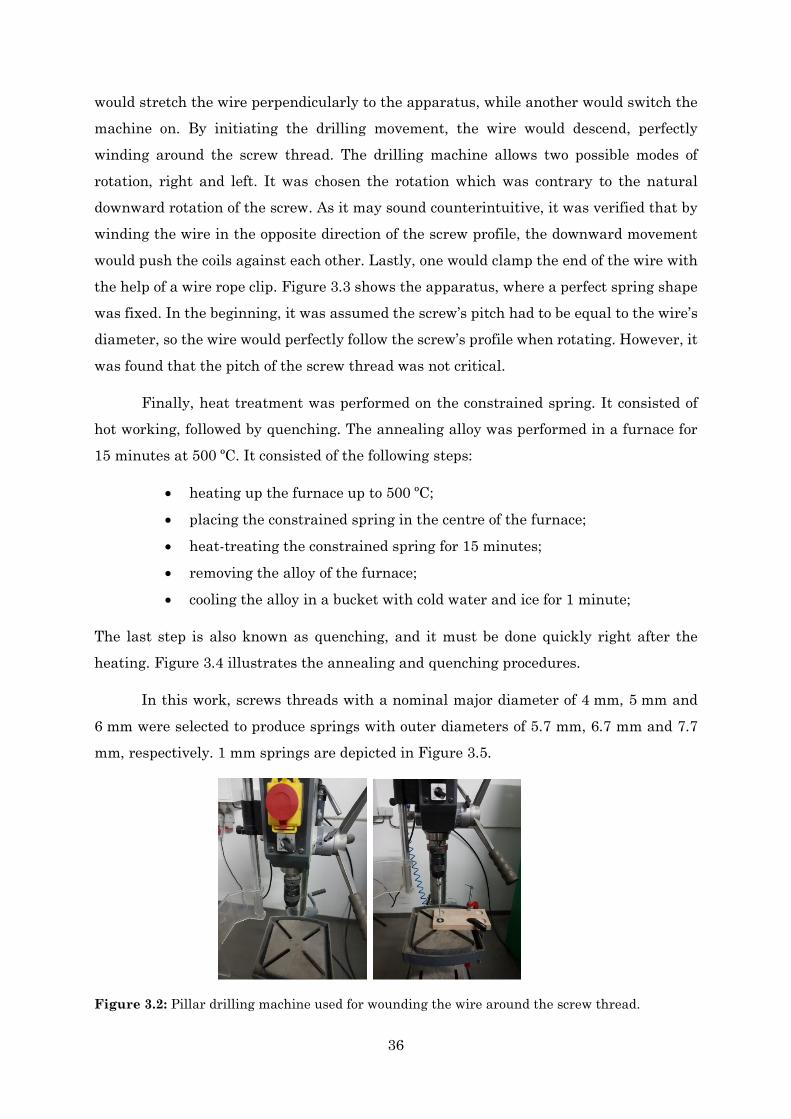
36
would stretch the wire perpendicularly to the apparatus, while another would switch the machine on. By initiating the drilling movement, the wire would descend, perfectly winding around the screw thread. The drilling machine allows two possible modes of rotation, right and left. It was chosen the rotation which was contrary to the natural downward rotation of the screw. As it may sound counterintuitive, it was verified that by winding the wire in the opposite direction of the screw profile, the downward movement would push the coils against each other. Lastly, one would clamp the end of the wire with the help of a wire rope clip. Figure 3.3 shows the apparatus, where a perfect spring shape was fixed. In the beginning, it was assumed the screw’s pitch had to be equal to the wire’s diameter, so the wire would perfectly follow the screw’s profile when rotating. However, it was found that the pitch of the screw thread was not critical.
Finally, heat treatment was performed on the constrained spring. It consisted of hot working, followed by quenching. The annealing alloy was performed in a furnace for 15 minutes at 500 ºC. It consisted of the following steps:
• heating up the furnace up to 500 ºC;
• placing the constrained spring in the centre of the furnace;
• heat-treating the constrained spring for 15 minutes;
• removing the alloy of the furnace;
• cooling the alloy in a bucket with cold water and ice for 1 minute;
The last step is also known as quenching, and it must be done quickly right after the heating. Figure 3.4 illustrates the annealing and quenching procedures.
In this work, screws threads with a nominal major diameter of 4 mm, 5 mm and 6 mm were selected to produce springs with outer diameters of 5.7 mm, 6.7 mm and 7.7 mm, respectively. 1 mm springs are depicted in Figure 3.5.
Figure 3.2: Pillar drilling machine used for wounding the wire around the screw thread.
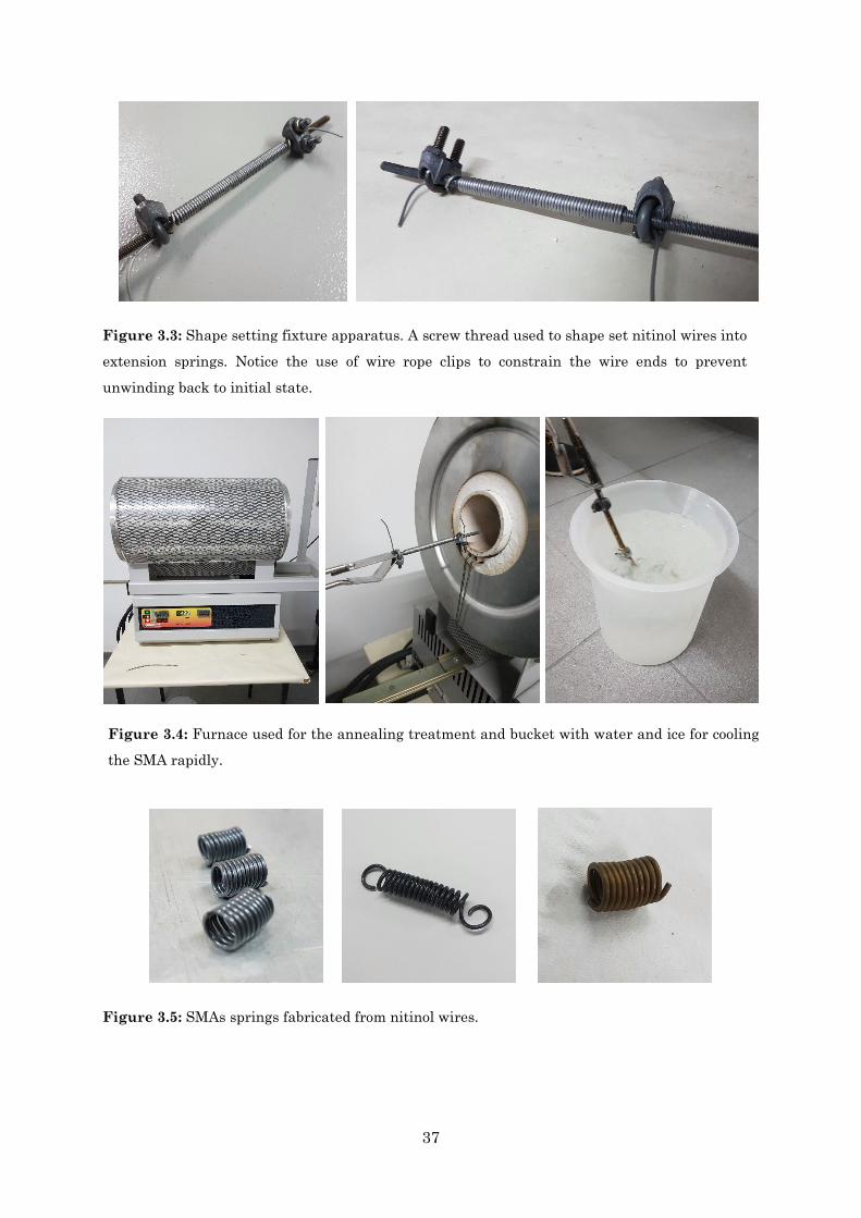
37
Figure 3.5: SMAs springs fabricated from nitinol wires.
Figure 3.3: Shape setting fixture apparatus. A screw thread used to shape set nitinol wires into
extension springs. Notice the use of wire rope clips to constrain the wire ends to prevent
unwinding back to initial state.
Figure 3.4: Furnace used for the annealing treatment and bucket with water and ice for cooling
the SMA rapidly.
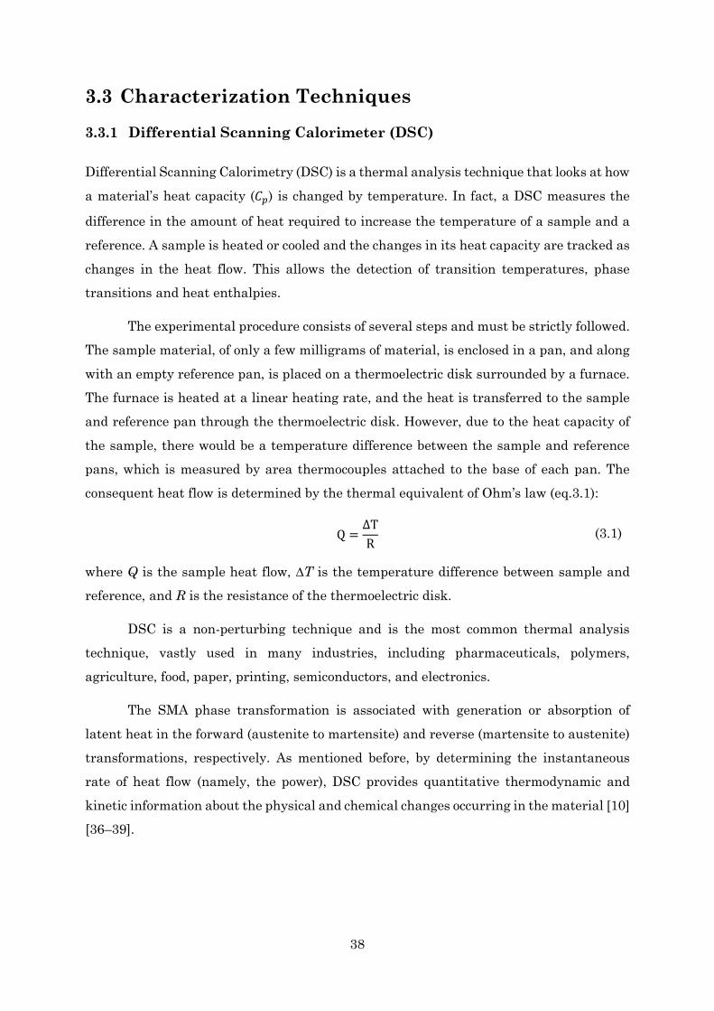
38
3.3 Characterization Techniques 3.3.1 Differential Scanning Calorimeter (DSC)
Differential Scanning Calorimetry (DSC) is a thermal analysis technique that looks at how a material’s heat capacity (𝐶𝐶𝑝𝑝) is changed by temperature. In fact, a DSC measures the
difference in the amount of heat required to increase the temperature of a sample and a reference. A sample is heated or cooled and the changes in its heat capacity are tracked as changes in the heat flow. This allows the detection of transition temperatures, phase transitions and heat enthalpies.
The experimental procedure consists of several steps and must be strictly followed. The sample material, of only a few milligrams of material, is enclosed in a pan, and along with an empty reference pan, is placed on a thermoelectric disk surrounded by a furnace. The furnace is heated at a linear heating rate, and the heat is transferred to the sample and reference pan through the thermoelectric disk. However, due to the heat capacity of the sample, there would be a temperature difference between the sample and reference pans, which is measured by area thermocouples attached to the base of each pan. The consequent heat flow is determined by the thermal equivalent of Ohm’s law (eq.3.1):
Q =ΔTR
(3.1)
where Q is the sample heat flow, ∆T is the temperature difference between sample and reference, and R is the resistance of the thermoelectric disk.
DSC is a non-perturbing technique and is the most common thermal analysis technique, vastly used in many industries, including pharmaceuticals, polymers, agriculture, food, paper, printing, semiconductors, and electronics.
The SMA phase transformation is associated with generation or absorption of latent heat in the forward (austenite to martensite) and reverse (martensite to austenite) transformations, respectively. As mentioned before, by determining the instantaneous rate of heat flow (namely, the power), DSC provides quantitative thermodynamic and kinetic information about the physical and chemical changes occurring in the material [10] [36–39].
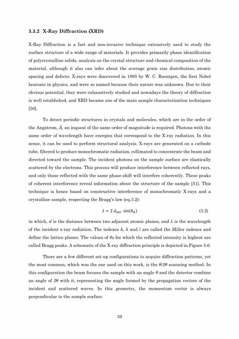
39
3.3.2 X-Ray Diffraction (XRD)
X-Ray Diffraction is a fast and non-invasive technique extensively used to study the surface structure of a wide range of materials. It provides primarily phase identification of polycrystalline solids, analysis on the crystal structure and chemical composition of the material, although it also can infer about the average grain size distribution, atomic spacing and defects. X-rays were discovered in 1895 by W. C. Roentgen, the first Nobel laureate in physics, and were so named because their nature was unknown. Due to their obvious potential, they were exhaustively studied and nowadays the theory of diffraction is well established, and XRD became one of the main sample characterization techniques [50].
To detect periodic structures in crystals and molecules, which are in the order of the Angstrom, Å, an inquest of the same order of magnitude is required. Photons with the same order of wavelength have energies that correspond to the X-ray radiation. In this sense, it can be used to perform structural analysis. X-rays are generated on a cathode tube, filtered to produce monochromatic radiation, collimated to concentrate the beam and directed toward the sample. The incident photons on the sample surface are elastically scattered by the electrons. This process will produce interference between reflected rays, and only those reflected with the same phase-shift will interfere coherently. These peaks of coherent interference reveal information about the structure of the sample [51]. This technique is hence based on constructive interference of monochromatic X-rays and a crystalline sample, respecting the Bragg’s law (eq.3.2):
𝜆𝜆 = 2 𝑑𝑑ℎ𝑘𝑘𝑘𝑘 sin(𝜃𝜃𝐵𝐵) (3.2)
in which, d is the distance between two adjacent atomic planes, and λ is the wavelength of the incident x-ray radiation. The indexes h, k and l are called the Miller indexes and define the lattice planes. The values of θB for which the reflected intensity is highest are called Bragg peaks. A schematic of the X-ray diffraction principle is depicted in Figure 3.6.
There are a few different set-up configurations to acquire diffraction patterns, yet the most common, which was the one used on this work, is the θ/2θ scanning method. In this configuration the beam focuses the sample with an angle θ and the detector combine an angle of 2θ with it, representing the angle formed by the propagation vectors of the incident and scattered waves. In this geometry, the momentum vector is always perpendicular to the sample surface.
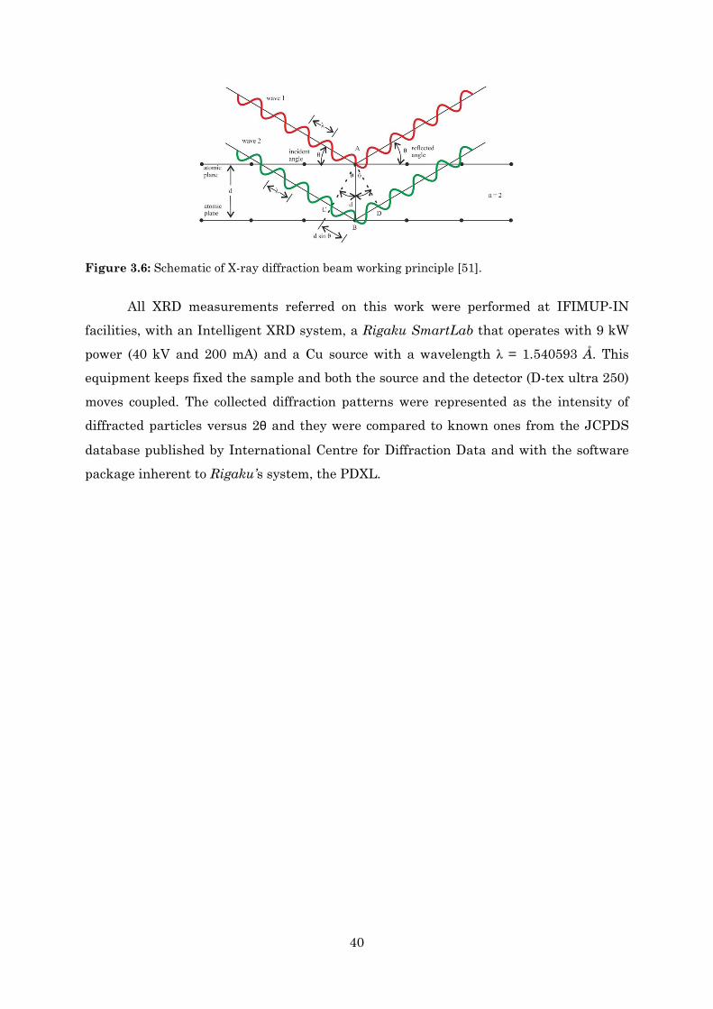
40
All XRD measurements referred on this work were performed at IFIMUP-IN facilities, with an Intelligent XRD system, a Rigaku SmartLab that operates with 9 kW power (40 kV and 200 mA) and a Cu source with a wavelength λ = 1.540593 Å. This equipment keeps fixed the sample and both the source and the detector (D-tex ultra 250) moves coupled. The collected diffraction patterns were represented as the intensity of diffracted particles versus 2θ and they were compared to known ones from the JCPDS
database published by International Centre for Diffraction Data and with the software package inherent to Rigaku’s system, the PDXL.
Figure 3.6: Schematic of X-ray diffraction beam working principle [51].

41
Chapter 4
4. Characterization and Control of SMA Springs
4.1 Characterization of SMA 4.1.1 Calorimetric Analysis
To shape wires into springs, the nitinol wire must be subjected to high stresses during an annealing treatment. Stress and coil diameter are intimately correlated. The higher the diameter, the lower the pressure the material is subjected. DSC measurements were done in order to investigate the effect of stress on transformation temperature. These temperatures were measured by Perkin Elmer Diamond differential scanning calorimetry at the temperature range between 0 ºC and 100 ºC in a nitrogen atmosphere.
Prior to the DSC measurements, it was required to perform a furnace conditioning. It consists of sweeping the temperature from -5 ºC to 110 ºC and back to 0 ºC under 60 ºC/min heating and cooling rates. Then, just with the empty pans, it was performed a temperature sweep from 0 ºC to 100 ºC and back to 0 ºC. This procedure is called the instrument baseline, i.e. the residual heat flow signal of the DSC when operated empty.
After the baseline sweep procedure, the measurements were performed under 10 and 40 ºC/min heating and cooling rates. The samples consisted of little fragments, with a mass of about 10-20 mg, of material regarding one straight NiTi wire and three NiTi springs. A non-annealed wire sample was also scanned for comparing with the annealed ones. The other samples were annealed for 15 minutes at 500 ºC and rapidly quenched in cold water (section 3.2).
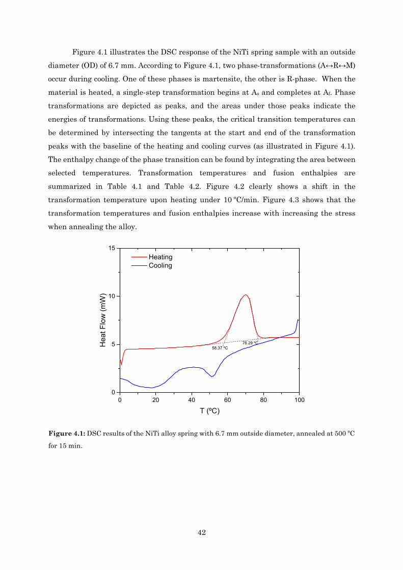
42
Figure 4.1 illustrates the DSC response of the NiTi spring sample with an outside diameter (OD) of 6.7 mm. According to Figure 4.1, two phase-transformations (A↔R↔M) occur during cooling. One of these phases is martensite, the other is R-phase. When the material is heated, a single-step transformation begins at As and completes at Af. Phase transformations are depicted as peaks, and the areas under those peaks indicate the energies of transformations. Using these peaks, the critical transition temperatures can be determined by intersecting the tangents at the start and end of the transformation peaks with the baseline of the heating and cooling curves (as illustrated in Figure 4.1). The enthalpy change of the phase transition can be found by integrating the area between selected temperatures. Transformation temperatures and fusion enthalpies are summarized in Table 4.1 and Table 4.2. Figure 4.2 clearly shows a shift in the transformation temperature upon heating under 10 ºC/min. Figure 4.3 shows that the transformation temperatures and fusion enthalpies increase with increasing the stress when annealing the alloy.
Figure 4.1: DSC results of the NiTi alloy spring with 6.7 mm outside diameter, annealed at 500 ºC
for 15 min.
0 20 40 60 80 1000
5
10
15
76.29 ºC
Heating Cooling
Hea
t Flo
w (m
W)
T (ºC)
58.37 ºC
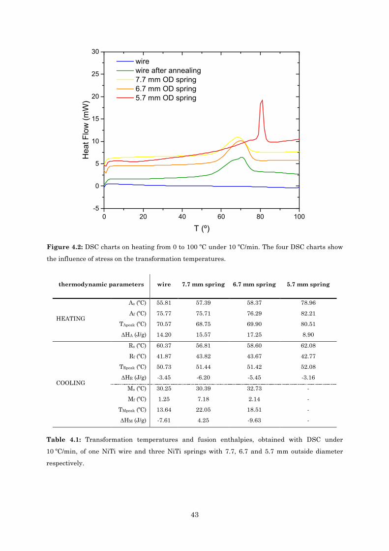
43
thermodynamic parameters wire 7.7 mm spring 6.7 mm spring 5.7 mm spring
HEATING
As (ºC) 55.81 57.39 58.37 78.96
Af (ºC) 75.77 75.71 76.29 82.21 TApeak (ºC) 70.57 68.75 69.90 80.51 ΔHA (J/g) 14.20 15.57 17.25 8.90
COOLING
Rs (ºC) 60.37 56.81 58.60 62.08
Rf (ºC) 41.87 43.82 43.67 42.77 TRpeak (ºC) 50.73 51.44 51.42 52.08 ΔHR (J/g) -3.45 -6.20 -5.45 -3.16
Ms (ºC) 30.25 30.39 32.73 - Mf (ºC) 1.25 7.18 2.14 -
TMpeak (ºC) 13.64 22.05 18.51 - ΔHM (J/g) -7.61 4.25 -9.63 -
Table 4.1: Transformation temperatures and fusion enthalpies, obtained with DSC under
10 ºC/min, of one NiTi wire and three NiTi springs with 7.7, 6.7 and 5.7 mm outside diameter
respectively.
0 20 40 60 80 100-5
0
5
10
15
20
25
30 wire wire after annealing 7.7 mm OD spring 6.7 mm OD spring 5.7 mm OD spring
Hea
t Flo
w (m
W)
T (º)
Figure 4.2: DSC charts on heating from 0 to 100 ºC under 10 ºC/min. The four DSC charts show
the influence of stress on the transformation temperatures.
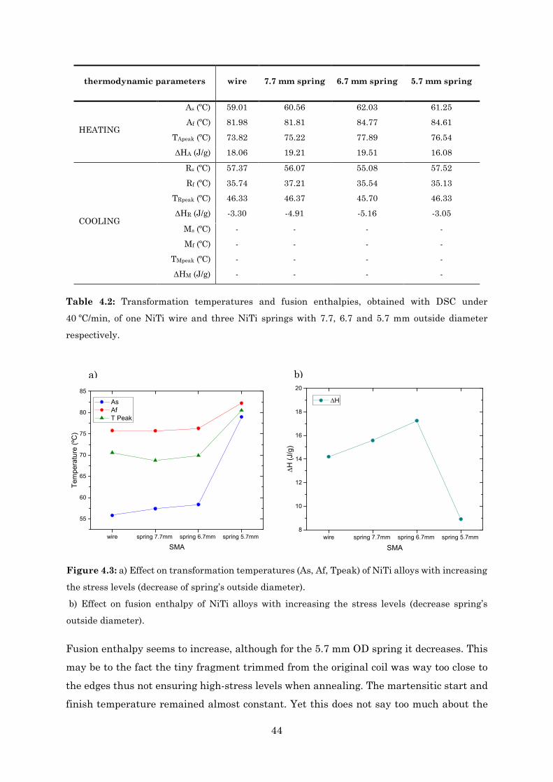
44
thermodynamic parameters wire 7.7 mm spring 6.7 mm spring 5.7 mm spring
HEATING
As (ºC) 59.01 60.56 62.03 61.25 Af (ºC) 81.98 81.81 84.77 84.61
TApeak (ºC) 73.82 75.22 77.89 76.54 ΔHA (J/g) 18.06 19.21 19.51 16.08
COOLING
Rs (ºC) 57.37 56.07 55.08 57.52
Rf (ºC) 35.74 37.21 35.54 35.13 TRpeak (ºC) 46.33 46.37 45.70 46.33 ΔHR (J/g) -3.30 -4.91 -5.16 -3.05
Ms (ºC) - - - - Mf (ºC) - - - -
TMpeak (ºC) - - - - ΔHM (J/g) - - - -
Table 4.2: Transformation temperatures and fusion enthalpies, obtained with DSC under
40 ºC/min, of one NiTi wire and three NiTi springs with 7.7, 6.7 and 5.7 mm outside diameter
respectively.
Fusion enthalpy seems to increase, although for the 5.7 mm OD spring it decreases. This may be to the fact the tiny fragment trimmed from the original coil was way too close to the edges thus not ensuring high-stress levels when annealing. The martensitic start and finish temperature remained almost constant. Yet this does not say too much about the
wire spring 7.7mm spring 6.7mm spring 5.7mm
55
60
65
70
75
80
85
As Af T Peak
Tem
pera
ture
(ºC
)
SMAwire spring 7.7mm spring 6.7mm spring 5.7mm
8
10
12
14
16
18
20
∆H
∆H
(J/g
)
SMA
Figure 4.3: a) Effect on transformation temperatures (As, Af, Tpeak) of NiTi alloys with increasing
the stress levels (decrease of spring’s outside diameter).
b) Effect on fusion enthalpy of NiTi alloys with increasing the stress levels (decrease spring’s
outside diameter).
a) b)
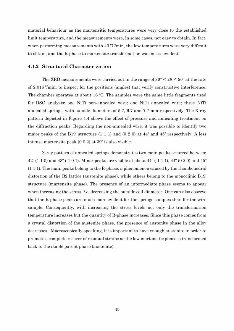
45
material behaviour as the martensitic temperatures were very close to the established limit temperature, and the measurements were, in some cases, not easy to obtain. In fact, when performing measurements with 40 ºC/min, the low temperatures were very difficult to obtain, and the R-phase to martensite transformation was not so evident.
4.1.2 Structural Characterization
The XRD measurements were carried out in the range of 30° ≤ 2𝜃𝜃 ≤ 50° at the rate of 2.016 º/min, to inspect for the positions (angles) that verify constructive interference. The chamber operates at about 18 ºC. The samples were the same little fragments used for DSC analysis: one NiTi non-annealed wire; one NiTi annealed wire; three NiTi annealed springs, with outside diameters of 5.7, 6.7 and 7.7 mm respectively. The X-ray pattern depicted in Figure 4.4 shows the effect of pressure and annealing treatment on the diffraction peaks. Regarding the non-annealed wire, it was possible to identify two major peaks of the B19’ structure (1 1 1) and (0 2 0) at 44º and 45º respectively. A less intense martensite peak (0 0 2) at 39º is also visible.
X-ray pattern of annealed springs demonstrates two main peaks occurred between 42º (1 1 0) and 43º (-1 0 1). Minor peaks are visible at about 41º (-1 1 1), 44º (0 2 0) and 45º (1 1 1). The main peaks belong to the R-phase, a phenomenon caused by the rhombohedral distortion of the B2 lattice (austenite phase), while others belong to the monoclinic B19’ structure (martensite phase). The presence of an intermediate phase seems to appear when increasing the stress, i.e. decreasing the outside coil diameter. One can also observe that the R-phase peaks are much more evident for the springs samples than for the wire sample. Consequently, with increasing the stress levels not only the transformation temperature increases but the quantity of R-phase increases. Since this phase comes from a crystal distortion of the austenite phase, the presence of austenite phase in the alloy decreases. Macroscopically speaking, it is important to have enough austenite in order to promote a complete recover of residual strains as the low martensitic phase is transformed back to the stable parent phase (austenite).
46
4.1.3 Thermomechanical Characterization
Aiming to develop an efficient spring to actuate in a scissor lift platform, it was necessary to understand its design limits. As described in previous chapters, the spring elastic constant κ depends on several geometric parameters and a shear modulus G. In this section the results respecting the determination of the austenite shear modulus G are presented. It is also presented the temperature behaviour across the SMA spring, which was possible due to the development of a control system. Analysis of power parameters and response times are given.
30 32 34 36 38 40 42 44 46 48 50
(0 0
2) M
I/Im
ax
2θ (º)
spring 5.7 mm OD
(0 2
0) M
(1 1
1) M
(1 1
1) M
(0 2
0) M
(1 1
1) M
(0 2
0) M
(0 0
2) M
(0 0
2) M
(0 0
2) M
(1 1
0) R
wire
wire after annealing
spring 7.7 mm OD
(1 1
1) M
spring 6.7 mm OD
(0 2
0) M
(-1 0
1) R
(0 2
0) M
(1 1
0) R
(-1 0
1) R
(1 1
0) R
(-1 0
1) R
Figure 4.4: XRD results of five NiTi alloys samples: one NiTi non-annealed wire; one NiTi
annealed wire; three NiTi annealed springs, with outside diameters of 5.7, 6.7 and 7.7 mm
respectively.
47
4.1.3.1 Austenitic Shear Modulus G
With the use of a turnbuckle into the apparatus depicted in Figure 4.5, it was possible to measure the spring elongation upon stress and heating. The spring was clamped between two (conductive) metal plates, in which a potential difference was applied. By fixing the dynamometer and the end of the turnbuckle, it was also possible to estimate the forces which the springs may exert when actuated.
In all characterization tests, the applied voltage to the SMAs springs was 1.1 V, being the typical electrical current 6.3 A, and therefore the dissipated power was approximately 6.9 W. Under actuation, the different springs were stretched by rotating the turnbuckle and the force was measured using a dynamometer. This was repeated until it was reached an elongation of 2.4 cm (about 15 rotations). One turn of the stretching screw corresponds to 0.8 mm displacement of one screw, therefore 1.6 mm of elongation on the spring. For each data point (force and elongation) it was taken into account a bias elongation, regarding the length of the spring upon stress and heating, La, and a bias force regarding the weight of the apparatus (turnbuckle, screws, electric wires, fixation metal sheets, etc).
Results for three springs with different outside coil diameters (5.7 mm, 6.7 mm and 7.7 mm) are depicted in Figure 4.6. A maximum force of 34 N and 2.4 cm displacement
were obtained. From the linear fit it was possible to get the spring elastic constant κ and consequently G. The austenitic shear modulus was estimated to be 𝐺𝐺 ≅ 13.09 𝐺𝐺𝐺𝐺𝐺𝐺 through a weighted arithmetic mean regarding R2 (from the linear regression). Linear fits were calculated with respect to the linear regions obtained from data. For the small springs (5.7 and 6.7 mm outside diameter) there is a slight shift in the slope for high forces. That may be to the effect of the plastic deformation initiated in the austenite phase, when the plastic strain limit has been exceeded. Notice that the springs with smaller diameter were subjected to greater torsion forces, so for lower elongations the plastic regime was easily reached.
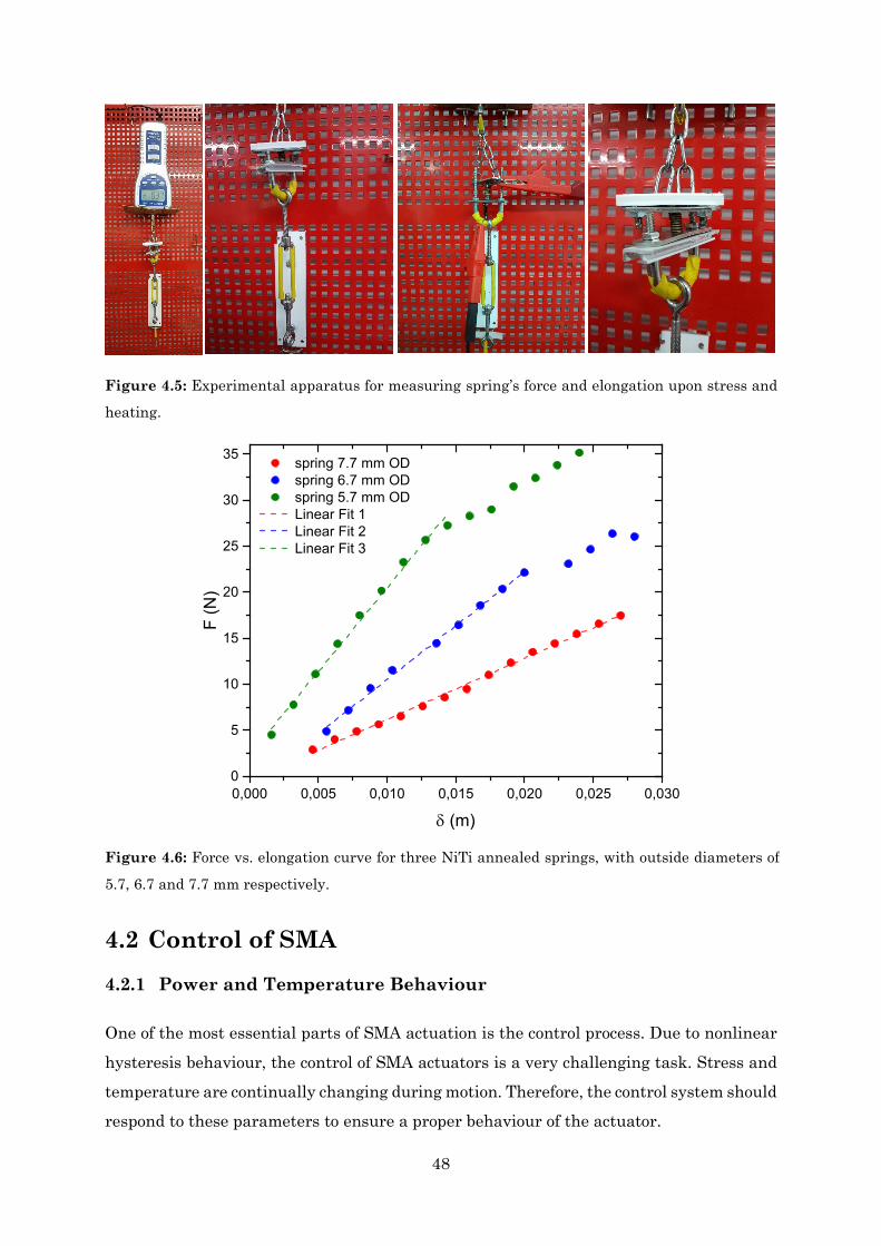
48
4.2 Control of SMA 4.2.1 Power and Temperature Behaviour
One of the most essential parts of SMA actuation is the control process. Due to nonlinear hysteresis behaviour, the control of SMA actuators is a very challenging task. Stress and temperature are continually changing during motion. Therefore, the control system should respond to these parameters to ensure a proper behaviour of the actuator.
0,000 0,005 0,010 0,015 0,020 0,025 0,0300
5
10
15
20
25
30
35
F (N
)
δ (m)
spring 7.7 mm OD spring 6.7 mm OD spring 5.7 mm OD Linear Fit 1 Linear Fit 2 Linear Fit 3
Figure 4.6: Force vs. elongation curve for three NiTi annealed springs, with outside diameters of
5.7, 6.7 and 7.7 mm respectively.
Figure 4.5: Experimental apparatus for measuring spring’s force and elongation upon stress and
heating.

49
The actuation began by applying a voltage to the SMA spring which was therefore heated due to the Joule effect. The spring took a certain time to heat up and another time to cool down. It has experienced a large wait time to cool, as it depended mainly on the convection of the surrounding air. Notice that the spring also dissipated energy in the form of radiation.
Regarding the actuator’s control, a system based on a microcontroller (Arduino
Nano) was developed during this work (Figure 4.7). Two electric cables attached to the ends of the spring make the connection with the circuit. The function of the Arduino was to control the applied voltage to the SMA for a certain period of time. Parameters such as voltage percentage, time ON and time OFF, were chosen in the Docklight software, used as an interface.
To select a reasonable value for voltage and actuation time for the scissor lift prototype, several tests were made. First, by using a voltmeter and an amperemeter, as shown in Figure 4.8 it was possible to measure, in real-time, voltage, current and resistance across a 6.7 mm OD spring.
All the parameters were registered after 1 minute of turning ON the Arduino. To control the applied voltage to the spring, the Docklight software was used. The control was made by setting a percentage of the maximum voltage that the circuit can apply, which was near about 1V. Results are presented in Table 4.3 and Figure 4.9. It is verified that the resistance of the spring increases. Any resistor in a circuit that has a voltage drop across it dissipates electrical power. In this circuit, the spring acts as a resistor, so it dissipates power in the form of heat, referred as Joule heating. In particular, the electric energy is converted to heat through resistive losses in the material and heat is generated
Figure 4.7: Control of the applied voltage across an SMA spring using an Arduino Nano.
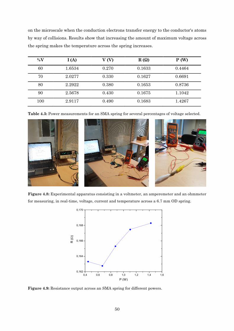
50
on the microscale when the conduction electrons transfer energy to the conductor's atoms by way of collisions. Results show that increasing the amount of maximum voltage across the spring makes the temperature across the spring increases.
Table 4.3: Power measurements for an SMA spring for several percentages of voltage selected.
%V I (A) V (V) R (Ω) P (W)
60 1.6534 0.270 0.1633 0.4464
70 2.0277 0.330 0.1627 0.6691
80 2.2922 0.380 0.1653 0.8736
90 2.5678 0.430 0.1675 1.1042
100 2.9117 0.490 0.1683 1.4267
0,4 0,6 0,8 1,0 1,2 1,4 1,60,162
0,164
0,166
0,168
0,170
R (Ω
)
P (W)
Figure 4.9: Resistance output across an SMA spring for different powers.
Figure 4.8: Experimental apparatus consisting in a voltmeter, an amperemeter and an ohmmeter
for measuring, in real-time, voltage, current and temperature across a 6.7 mm OD spring.
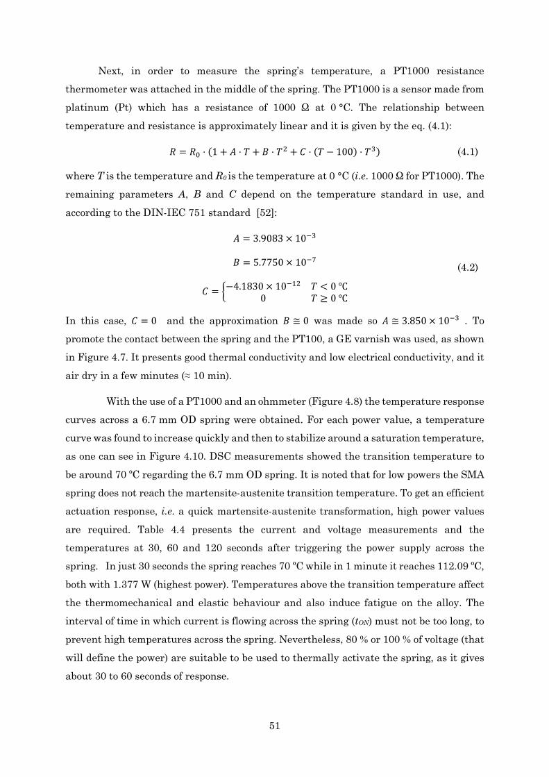
51
Next, in order to measure the spring’s temperature, a PT1000 resistance thermometer was attached in the middle of the spring. The PT1000 is a sensor made from platinum (Pt) which has a resistance of 1000 Ω at 0 °C. The relationship between temperature and resistance is approximately linear and it is given by the eq. (4.1):
𝑅𝑅 = 𝑅𝑅0 ⋅ (1 + 𝐴𝐴 ⋅ 𝑇𝑇 + 𝐵𝐵 ⋅ 𝑇𝑇2 + 𝐶𝐶 ⋅ (𝑇𝑇 − 100) ⋅ 𝑇𝑇3) (4.1)
where T is the temperature and R0 is the temperature at 0 °C (i.e. 1000 Ω for PT1000). The remaining parameters A, B and C depend on the temperature standard in use, and according to the DIN-IEC 751 standard [52]:
𝐴𝐴 = 3.9083 × 10⁻³
𝐵𝐵 = 5.7750 × 10⁻⁷
𝐶𝐶 = −4.1830 × 10⁻¹² 𝑇𝑇 < 0 0 𝑇𝑇 ≥ 0
(4.2)
In this case, 𝐶𝐶 = 0 and the approximation 𝐵𝐵 ≅ 0 was made so 𝐴𝐴 ≅ 3.850 × 10⁻³ . To promote the contact between the spring and the PT100, a GE varnish was used, as shown in Figure 4.7. It presents good thermal conductivity and low electrical conductivity, and it air dry in a few minutes (≈ 10 min).
With the use of a PT1000 and an ohmmeter (Figure 4.8) the temperature response curves across a 6.7 mm OD spring were obtained. For each power value, a temperature curve was found to increase quickly and then to stabilize around a saturation temperature, as one can see in Figure 4.10. DSC measurements showed the transition temperature to be around 70 ºC regarding the 6.7 mm OD spring. It is noted that for low powers the SMA spring does not reach the martensite-austenite transition temperature. To get an efficient actuation response, i.e. a quick martensite-austenite transformation, high power values are required. Table 4.4 presents the current and voltage measurements and the temperatures at 30, 60 and 120 seconds after triggering the power supply across the spring. In just 30 seconds the spring reaches 70 ºC while in 1 minute it reaches 112.09 ºC, both with 1.377 W (highest power). Temperatures above the transition temperature affect the thermomechanical and elastic behaviour and also induce fatigue on the alloy. The interval of time in which current is flowing across the spring (tON) must not be too long, to prevent high temperatures across the spring. Nevertheless, 80 % or 100 % of voltage (that will define the power) are suitable to be used to thermally activate the spring, as it gives about 30 to 60 seconds of response.

52
%V I (A) V (V) R (Ω) P (W) T30s (ºC) T60s (ºC) T120s (ºC)
20 0.568 0.108 0.190 0.061 30.93 37.13 38.79
40 1.184 0.188 0.159 0.223 40.76 46.85 52.20
60 1.759 0.283 0.161 0.499 49.87 67.63 96.13
80 2.323 0.382 0.165 0.888 56.09 95.67 121.69
100 2.864 0.481 0.168 1.377 70.13 112.09 141.16
Table 4.4: Power and temperature measurements regarding an SMA spring.
Additionally to the heating trials, tests to evaluate cooling time were also performed. First, to warm up the material it was applied 307 mV (80% of voltage) to a 6.7 mm OD spring. Figure 4.11 a) shows that the spring took about 7 minutes to cool to the room temperature (~25 ºC). The material took about 7 times more to cool down than to heat up. An expected result, as the alloy depends mostly on the convection of the surrounding air. At last, a 20-minute heating-cooling cycle was performed. The highest power was chosen (equivalent to 100 % of voltage), 30 seconds of time ON and 120 seconds of time OFF. From Figure 4.11 b) it is noticeable that the minimum temperature reached by the spring at the end of the cycle increases, as there is not enough time for the spring too cool to room temperature. Consequently, the maximum temperature reached by the spring under actuation also increases from cycle to cycle.
0 20 40 60 80 100 120 140 16020
40
60
80
100
120
140
160
T (º
C)
t (s)
100% Vmax (1.377 W) 80% Vmax (0.888 W) 60% Vmax (0.499 W) 40% Vmax (0.223 W) 20% Vmax (0.061 W)
70
Figure 4.10: Temperature curves across a 6.7 mm OD spring for different powers.
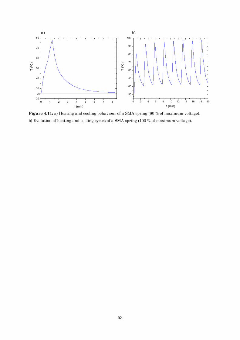
53
0 1 2 3 4 5 6 7 820
30
40
50
60
70
80
T (º
C)
t (min)
25
a) b)
0 2 4 6 8 10 12 14 16 18 20
30
40
50
60
70
80
90
100
T (º
C)
t (min)
Figure 4.11: a) Heating and cooling behaviour of a SMA spring (80 % of maximum voltage).
b) Evolution of heating and cooling cycles of a SMA spring (100 % of maximum voltage).

54
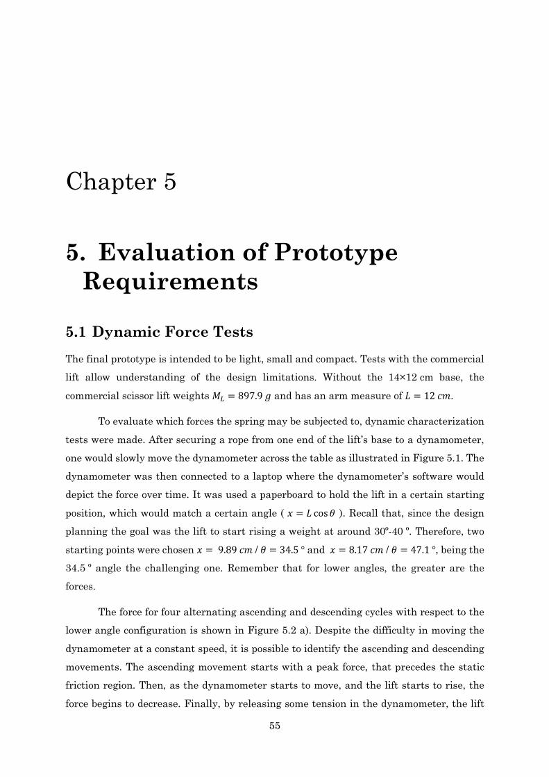
55
Chapter 5
5. Evaluation of Prototype Requirements
5.1 Dynamic Force Tests The final prototype is intended to be light, small and compact. Tests with the commercial lift allow understanding of the design limitations. Without the 14×12 cm base, the
commercial scissor lift weights 𝑀𝑀𝐿𝐿 = 897.9 𝑚𝑚 and has an arm measure of 𝐿𝐿 = 12 𝑐𝑐𝑚𝑚.
To evaluate which forces the spring may be subjected to, dynamic characterization tests were made. After securing a rope from one end of the lift’s base to a dynamometer, one would slowly move the dynamometer across the table as illustrated in Figure 5.1. The dynamometer was then connected to a laptop where the dynamometer’s software would depict the force over time. It was used a paperboard to hold the lift in a certain starting
position, which would match a certain angle ( 𝑥𝑥 = 𝐿𝐿 cos𝜃𝜃 ). Recall that, since the design planning the goal was the lift to start rising a weight at around 30º-40 º. Therefore, two starting points were chosen 𝑥𝑥 = 9.89 𝑐𝑐𝑚𝑚 / 𝜃𝜃 = 34.5 ° and 𝑥𝑥 = 8.17 𝑐𝑐𝑚𝑚 / 𝜃𝜃 = 47.1 °, being the 34.5 º angle the challenging one. Remember that for lower angles, the greater are the forces.
The force for four alternating ascending and descending cycles with respect to the lower angle configuration is shown in Figure 5.2 a). Despite the difficulty in moving the dynamometer at a constant speed, it is possible to identify the ascending and descending movements. The ascending movement starts with a peak force, that precedes the static friction region. Then, as the dynamometer starts to move, and the lift starts to rise, the force begins to decrease. Finally, by releasing some tension in the dynamometer, the lift
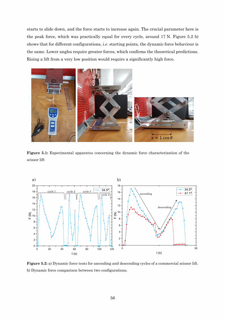
56
starts to slide down, and the force starts to increase again. The crucial parameter here is the peak force, which was practically equal for every cycle, around 17 N. Figure 5.2 b) shows that for different configurations, i.e. starting points, the dynamic force behaviour is the same. Lower angles require greater forces, which confirms the theoretical predictions. Rising a lift from a very low position would require a significantly high force.
0 20 40 60 80 100 1200
2
4
6
8
10
12
14
16
18
20
F (N
)
t (s)
34.5ºcycle 1 cycle 2 cycle 3 cycle 4
0 500
2
4
6
8
10
12
14
16
18
F (N
)
t (s)
34.5º 47.1ºascending
descending
a) b)
Figure 5.2: a) Dynamic force tests for ascending and descending cycles of a commercial scissor lift.
b) Dynamic force comparison between two configurations.
𝑥𝑥 = 𝐿𝐿 cos𝜃𝜃
Figure 5.1: Experimental apparatus concerning the dynamic force characterization of the
scissor lift
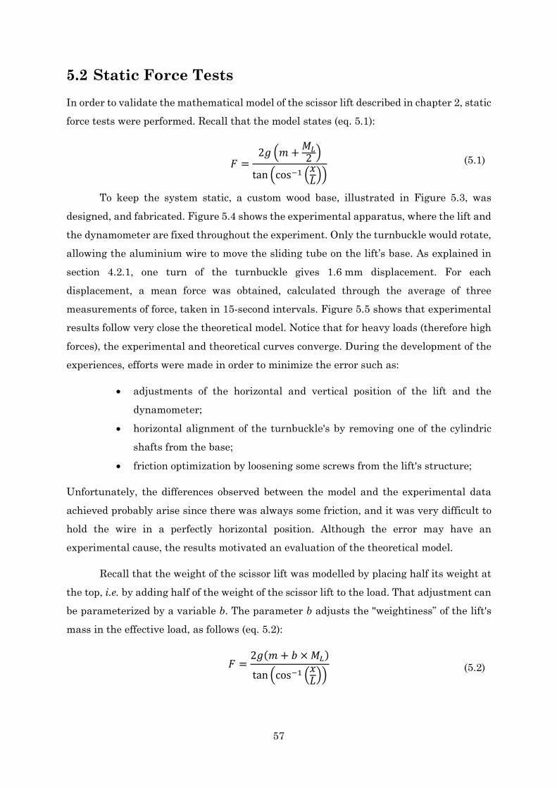
57
5.2 Static Force Tests In order to validate the mathematical model of the scissor lift described in chapter 2, static force tests were performed. Recall that the model states (eq. 5.1):
𝐹𝐹 =
2𝑚𝑚 𝑚𝑚 + 𝑀𝑀𝐿𝐿2
tan cos−1 𝑥𝑥𝐿𝐿 (5.1)
To keep the system static, a custom wood base, illustrated in Figure 5.3, was designed, and fabricated. Figure 5.4 shows the experimental apparatus, where the lift and the dynamometer are fixed throughout the experiment. Only the turnbuckle would rotate, allowing the aluminium wire to move the sliding tube on the lift’s base. As explained in section 4.2.1, one turn of the turnbuckle gives 1.6 mm displacement. For each displacement, a mean force was obtained, calculated through the average of three measurements of force, taken in 15-second intervals. Figure 5.5 shows that experimental results follow very close the theoretical model. Notice that for heavy loads (therefore high forces), the experimental and theoretical curves converge. During the development of the experiences, efforts were made in order to minimize the error such as:
• adjustments of the horizontal and vertical position of the lift and the dynamometer;
• horizontal alignment of the turnbuckle's by removing one of the cylindric shafts from the base;
• friction optimization by loosening some screws from the lift's structure;
Unfortunately, the differences observed between the model and the experimental data achieved probably arise since there was always some friction, and it was very difficult to hold the wire in a perfectly horizontal position. Although the error may have an experimental cause, the results motivated an evaluation of the theoretical model.
Recall that the weight of the scissor lift was modelled by placing half its weight at the top, i.e. by adding half of the weight of the scissor lift to the load. That adjustment can be parameterized by a variable b. The parameter b adjusts the "weightiness” of the lift's mass in the effective load, as follows (eq. 5.2):
𝐹𝐹 =
2𝑚𝑚(𝑚𝑚 + 𝑏𝑏 × 𝑀𝑀𝐿𝐿)
tan cos−1 𝑥𝑥𝐿𝐿 (5.2)
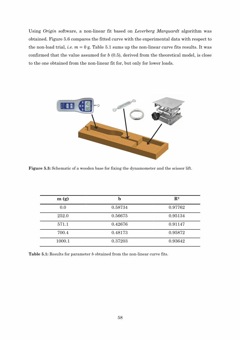
58
Using Origin software, a non-linear fit based on Leverberg Marquardt algorithm was obtained. Figure 5.6 compares the fitted curve with the experimental data with respect to the non-load trial, i.e. 𝑚𝑚 = 0 g. Table 5.1 sums up the non-linear curve fits results. It was confirmed that the value assumed for b (0.5), derived from the theoretical model, is close to the one obtained from the non-linear fit for, but only for lower loads.
m (g) b R2
0.0 0.58734 0.97762
252.0 0.56675 0.95134
571.1 0.42676 0.91147
700.4 0.48173 0.95872
1000.1 0.37203 0.93642
Table 5.1: Results for parameter b obtained from the non-linear curve fits.
Figure 5.3: Schematic of a wooden base for fixing the dynamometer and the scissor lift.
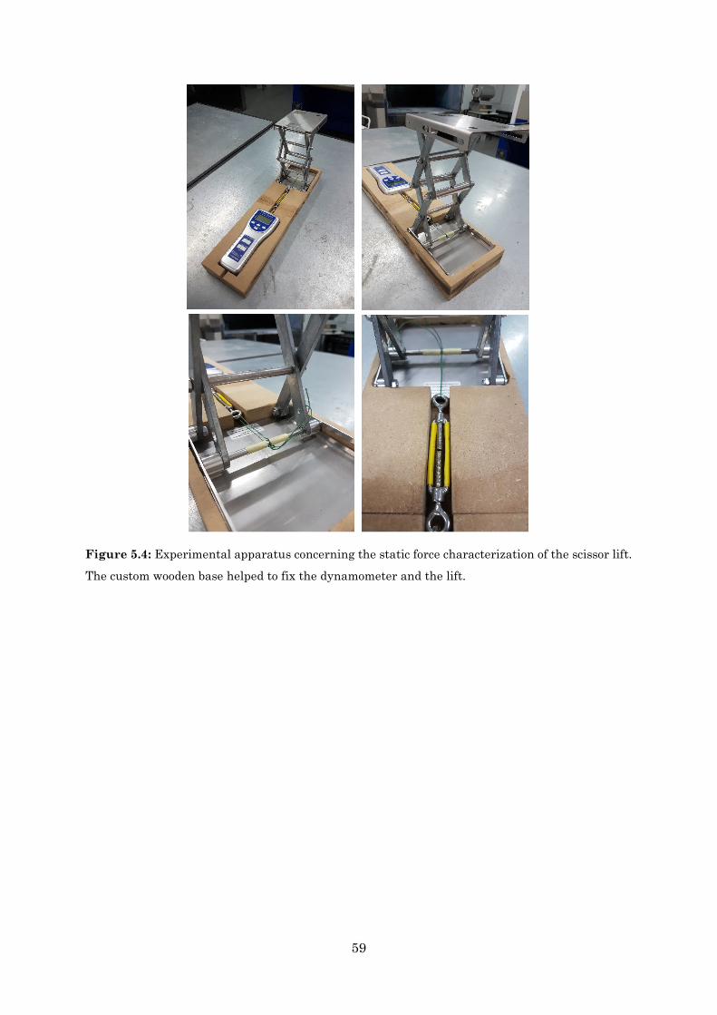
59
Figure 5.4: Experimental apparatus concerning the static force characterization of the scissor lift.
The custom wooden base helped to fix the dynamometer and the lift.

60
7 8 9 10 11 120
10
20
30
40
50
60F
(N)
∆x (cm)
Fexperimental data Ftheorical line
m = 252 g
6 7 8 9 10 110
10
20
30
40
50
F (N
)
∆x (cm)
Fexperimental data
Ftheorical line
m = 571 g
6 7 8 9 10 11
10
20
30
40
50
60
F (N
)
∆x (cm)
Fexperimental data
Ftheorical line
m = 704 g
6 7 8 9 10 11
10
20
30
40
50
60
F (N
)
∆x (cm)
Fexperimental data Ftheorical line
m = 1000 g
Figure 5.5: Experimental and theoretical static force vs lift's displacement curves.
7 8 9 10 11 120
10
20
30
40
50
F (N
)
∆x (cm)
Fexperimental data
Fnon-linear fit Ftheorical line
m = 0 g
Figure 5.6: Comparison between experimental, theoretical and non-linear fit curves with respect
to the non-load trial.
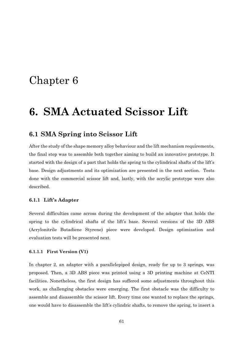
61
Chapter 6
6. SMA Actuated Scissor Lift
6.1 SMA Spring into Scissor Lift After the study of the shape memory alloy behaviour and the lift mechanism requirements, the final step was to assemble both together aiming to build an innovative prototype. It started with the design of a part that holds the spring to the cylindrical shafts of the lift’s base. Design adjustments and its optimization are presented in the next section. Tests done with the commercial scissor lift and, lastly, with the acrylic prototype were also described.
6.1.1 Lift’s Adapter
Several difficulties came across during the development of the adapter that holds the spring to the cylindrical shafts of the lift’s base. Several versions of the 3D ABS (Acrylonitrile Butadiene Styrene) piece were developed. Design optimization and evaluation tests will be presented next.
6.1.1.1 First Version (V1)
In chapter 2, an adapter with a parallelepiped design, ready for up to 3 springs, was proposed. Then, a 3D ABS piece was printed using a 3D printing machine at CeNTI facilities. Nonetheless, the first design has suffered some adjustments throughout this work, as challenging obstacles were emerging. The first obstacle was the difficulty to assemble and disassemble the scissor lift. Every time one wanted to replace the springs, one would have to disassemble the lift’s cylindric shafts, to remove the spring, to insert a
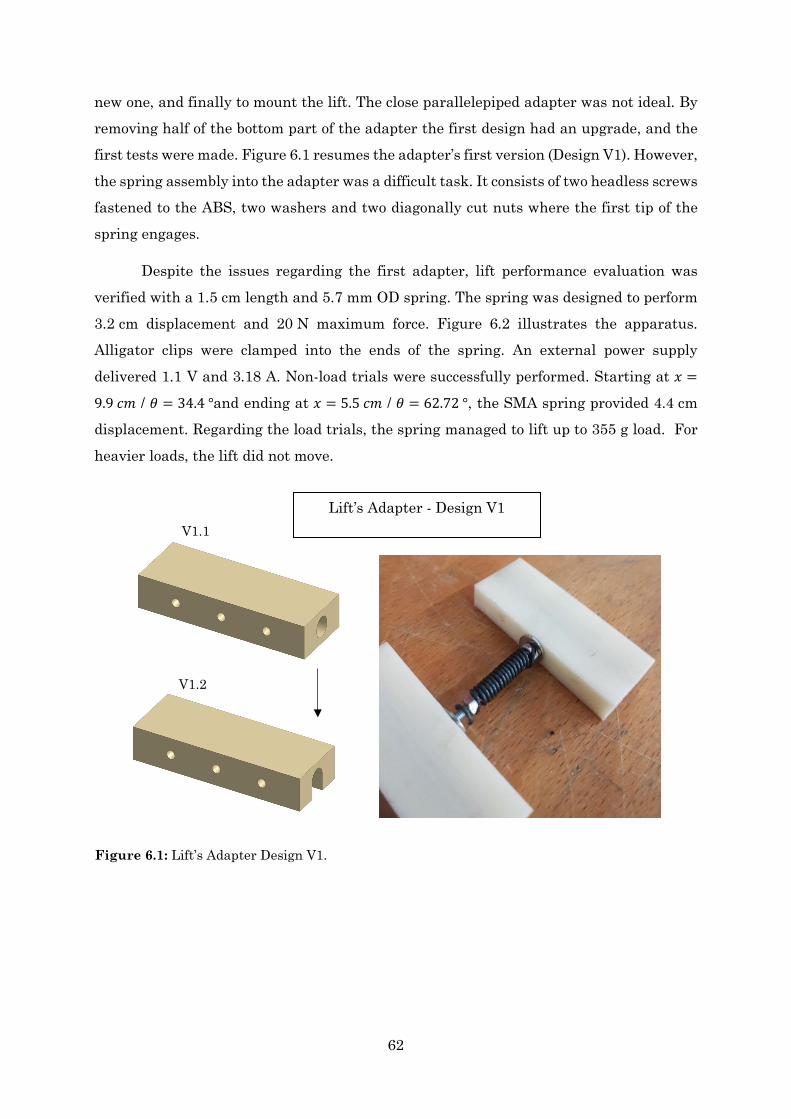
62
new one, and finally to mount the lift. The close parallelepiped adapter was not ideal. By removing half of the bottom part of the adapter the first design had an upgrade, and the first tests were made. Figure 6.1 resumes the adapter’s first version (Design V1). However, the spring assembly into the adapter was a difficult task. It consists of two headless screws fastened to the ABS, two washers and two diagonally cut nuts where the first tip of the spring engages.
Despite the issues regarding the first adapter, lift performance evaluation was verified with a 1.5 cm length and 5.7 mm OD spring. The spring was designed to perform 3.2 cm displacement and 20 N maximum force. Figure 6.2 illustrates the apparatus. Alligator clips were clamped into the ends of the spring. An external power supply delivered 1.1 V and 3.18 A. Non-load trials were successfully performed. Starting at 𝑥𝑥 =
9.9 𝑐𝑐𝑚𝑚 / 𝜃𝜃 = 34.4 °and ending at 𝑥𝑥 = 5.5 𝑐𝑐𝑚𝑚 / 𝜃𝜃 = 62.72 °, the SMA spring provided 4.4 cm displacement. Regarding the load trials, the spring managed to lift up to 355 g load. For heavier loads, the lift did not move.
Lift’s Adapter - Design V1 V1.1
V1.2
Figure 6.1: Lift’s Adapter Design V1.
63
6.1.1.2 Second Version (V2)
Although the adapter works as expected, the spring installation into the adapter was no easy task. To overcome this problem a second design was proposed. Instead of attaching the spring with diagonally cut nuts and headless screws, one would use ring terminal crimps and screws. The ring terminal crimp allows electrical connection with the power supply, and act as a washer too. The screw tightens the coil end, the crimp and the ABS together as shown in Figure 6.3. With this solution, it was much easier and faster to change the springs whenever needed. Further, by using two springs it was possible to power the springs just by one side, as the current would flow through the springs and screws closing the loop.
A spring with the same characteristics as before was used in this second version design. Lift’s performance tests were done with success. Figure 6.4 shows that using just one spring on top of the adapter makes it tilt. Then the adapter was tested with two springs. As the force exerted was too great the adapter was always loosening from the
Figure 6.2: Scissor Lift actuated by a SMA spring using the V1.2 ABS adapter.
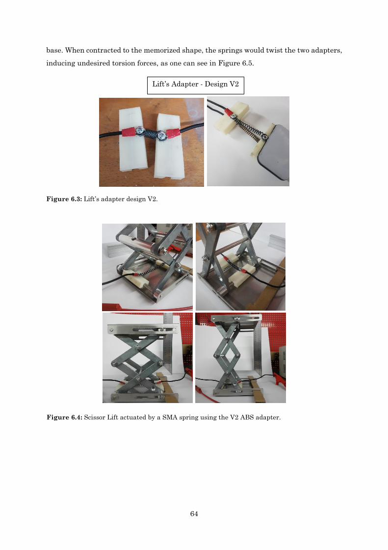
64
base. When contracted to the memorized shape, the springs would twist the two adapters, inducing undesired torsion forces, as one can see in Figure 6.5.
Lift’s Adapter - Design V2
Figure 6.3: Lift’s adapter design V2.
Figure 6.4: Scissor Lift actuated by a SMA spring using the V2 ABS adapter.
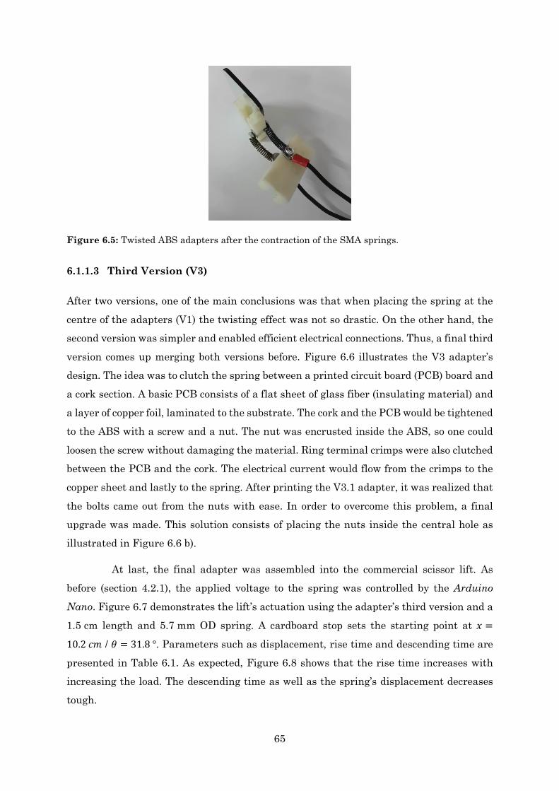
65
6.1.1.3 Third Version (V3)
After two versions, one of the main conclusions was that when placing the spring at the centre of the adapters (V1) the twisting effect was not so drastic. On the other hand, the second version was simpler and enabled efficient electrical connections. Thus, a final third version comes up merging both versions before. Figure 6.6 illustrates the V3 adapter’s design. The idea was to clutch the spring between a printed circuit board (PCB) board and a cork section. A basic PCB consists of a flat sheet of glass fiber (insulating material) and a layer of copper foil, laminated to the substrate. The cork and the PCB would be tightened to the ABS with a screw and a nut. The nut was encrusted inside the ABS, so one could loosen the screw without damaging the material. Ring terminal crimps were also clutched between the PCB and the cork. The electrical current would flow from the crimps to the copper sheet and lastly to the spring. After printing the V3.1 adapter, it was realized that the bolts came out from the nuts with ease. In order to overcome this problem, a final upgrade was made. This solution consists of placing the nuts inside the central hole as illustrated in Figure 6.6 b).
At last, the final adapter was assembled into the commercial scissor lift. As before (section 4.2.1), the applied voltage to the spring was controlled by the Arduino
Nano. Figure 6.7 demonstrates the lift’s actuation using the adapter’s third version and a 1.5 cm length and 5.7 mm OD spring. A cardboard stop sets the starting point at 𝑥𝑥 =
10.2 𝑐𝑐𝑚𝑚 / 𝜃𝜃 = 31.8 °. Parameters such as displacement, rise time and descending time are presented in Table 6.1. As expected, Figure 6.8 shows that the rise time increases with increasing the load. The descending time as well as the spring’s displacement decreases tough.
Figure 6.5: Twisted ABS adapters after the contraction of the SMA springs.
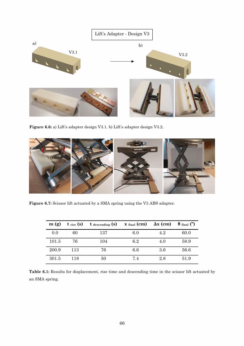
66
m (g) t rise (s) t descending (s) x final (cm) Δx (cm) θ final (º)
0.0 60 137 6.0 4.2 60.0
101.5 76 104 6.2 4.0 58.9
200.9 113 76 6.6 3.6 56.6
301.5 118 50 7.4 2.8 51.9
Table 6.1: Results for displacement, rise time and descending time in the scissor lift actuated by
an SMA spring.
Lift’s Adapter - Design V3
V3.1 V3.2
a) b)
Figure 6.6: a) Lift’s adapter design V3.1. b) Lift’s adapter design V3.2.
Figure 6.7: Scissor lift actuated by a SMA spring using the V3 ABS adapter.
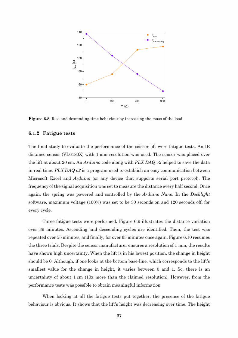
67
6.1.2 Fatigue tests
The final study to evaluate the performance of the scissor lift were fatigue tests. An IR distance sensor (VL6180X) with 1 mm resolution was used. The sensor was placed over the lift at about 20 cm. An Arduino code along with PLX DAQ v2 helped to save the data in real time. PLX DAQ v2 is a program used to establish an easy communication between Microsoft Excel and Arduino (or any device that supports serial port protocol). The frequency of the signal acquisition was set to measure the distance every half second. Once again, the spring was powered and controlled by the Arduino Nano. In the Docklight software, maximum voltage (100%) was set to be 30 seconds on and 120 seconds off, for every cycle.
Three fatigue tests were performed. Figure 6.9 illustrates the distance variation over 39 minutes. Ascending and descending cycles are identified. Then, the test was repeated over 55 minutes, and finally, for over 65 minutes once again. Figure 6.10 resumes the three trials. Despite the sensor manufacturer ensures a resolution of 1 mm, the results have shown high uncertainty. When the lift is in his lowest position, the change in height should be 0. Although, if one looks at the bottom base-line, which corresponds to the lift’s smallest value for the change in height, it varies between 0 and 1. So, there is an uncertainty of about 1 cm (10x more than the claimed resolution). However, from the performance tests was possible to obtain meaningful information.
When looking at all the fatigue tests put together, the presence of the fatigue behaviour is obvious. It shows that the lift’s height was decreasing over time. The height
0 100 200 30040
60
80
100
120
140
t rise (
s)
m (g)
trise
tdescending
Figure 6.8: Rise and descending time behaviour by increasing the mass of the load.
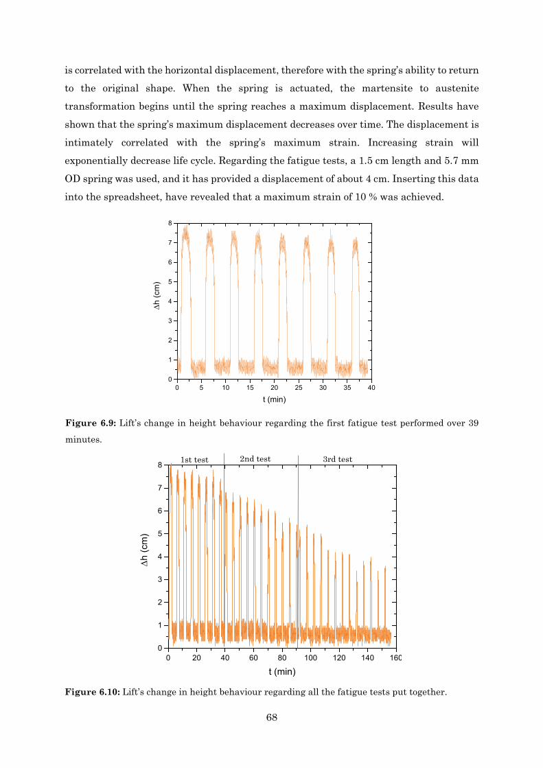
68
is correlated with the horizontal displacement, therefore with the spring’s ability to return to the original shape. When the spring is actuated, the martensite to austenite transformation begins until the spring reaches a maximum displacement. Results have shown that the spring’s maximum displacement decreases over time. The displacement is intimately correlated with the spring’s maximum strain. Increasing strain will exponentially decrease life cycle. Regarding the fatigue tests, a 1.5 cm length and 5.7 mm OD spring was used, and it has provided a displacement of about 4 cm. Inserting this data into the spreadsheet, have revealed that a maximum strain of 10 % was achieved.
0 5 10 15 20 25 30 35 400
1
2
3
4
5
6
7
8
∆h
(cm
)
t (min)
Figure 6.9: Lift’s change in height behaviour regarding the first fatigue test performed over 39
minutes.
Figure 6.10: Lift’s change in height behaviour regarding all the fatigue tests put together.
1st test 2nd test 3rd test
0 20 40 60 80 100 120 140 1600
1
2
3
4
5
6
7
8
∆h
(cm
)
t (min)
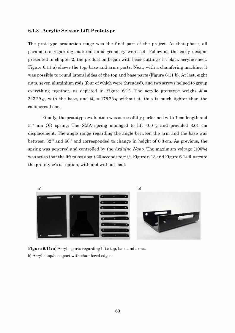
69
6.1.3 Acrylic Scissor Lift Prototype
The prototype production stage was the final part of the project. At that phase, all parameters regarding materials and geometry were set. Following the early designs presented in chapter 2, the production began with laser cutting of a black acrylic sheet. Figure 6.11 a) shows the top, base and arms parts. Next, with a chamfering machine, it was possible to round lateral sides of the top and base parts (Figure 6.11 b). At last, eight nuts, seven aluminium rods (four of which were threaded), and two screws helped to group everything together, as depicted in Figure 6.12. The acrylic prototype weighs 𝑀𝑀 =
242.29 𝑚𝑚, with the base, and 𝑀𝑀𝐿𝐿 = 178.26 𝑚𝑚 without it, thus is much lighter than the commercial one.
Finally, the prototype evaluation was successfully performed with 1 cm length and 5.7 mm OD spring. The SMA spring managed to lift 400 g and provided 3.61 cm displacement. The angle range regarding the angle between the arm and the base was between 32 º and 66 º and corresponded to change in height of 6.3 cm. As previous, the spring was powered and controlled by the Arduino Nano. The maximum voltage (100%) was set so that the lift takes about 20 seconds to rise. Figure 6.13 and Figure 6.14 illustrate the prototype’s actuation, with and without load.
Figure 6.11: a) Acrylic parts regarding lift’s top, base and arms.
b) Acrylic top/base part with chamfered edges.
a) b)
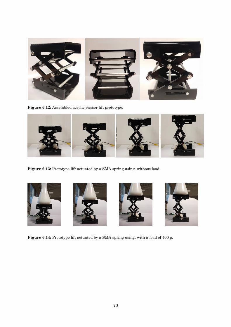
70
Figure 6.13: Prototype lift actuated by a SMA spring using, without load.
Figure 6.12: Assembled acrylic scissor lift prototype.
Figure 6.14: Prototype lift actuated by a SMA spring using, with a load of 400 g.
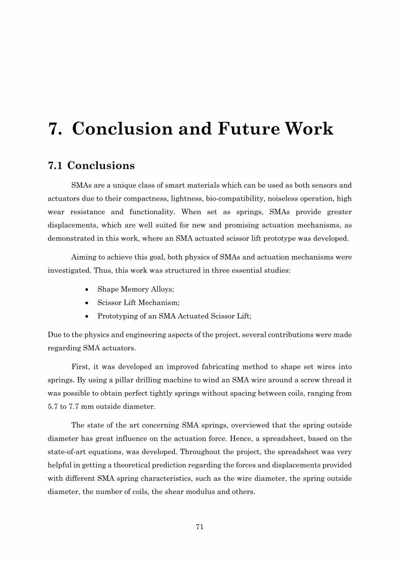
71
7. Conclusion and Future Work
7.1 Conclusions SMAs are a unique class of smart materials which can be used as both sensors and
actuators due to their compactness, lightness, bio-compatibility, noiseless operation, high wear resistance and functionality. When set as springs, SMAs provide greater displacements, which are well suited for new and promising actuation mechanisms, as demonstrated in this work, where an SMA actuated scissor lift prototype was developed.
Aiming to achieve this goal, both physics of SMAs and actuation mechanisms were investigated. Thus, this work was structured in three essential studies:
• Shape Memory Alloys;
• Scissor Lift Mechanism;
• Prototyping of an SMA Actuated Scissor Lift;
Due to the physics and engineering aspects of the project, several contributions were made regarding SMA actuators.
First, it was developed an improved fabricating method to shape set wires into springs. By using a pillar drilling machine to wind an SMA wire around a screw thread it was possible to obtain perfect tightly springs without spacing between coils, ranging from 5.7 to 7.7 mm outside diameter.
The state of the art concerning SMA springs, overviewed that the spring outside diameter has great influence on the actuation force. Hence, a spreadsheet, based on the state-of-art equations, was developed. Throughout the project, the spreadsheet was very helpful in getting a theoretical prediction regarding the forces and displacements provided with different SMA spring characteristics, such as the wire diameter, the spring outside diameter, the number of coils, the shear modulus and others.
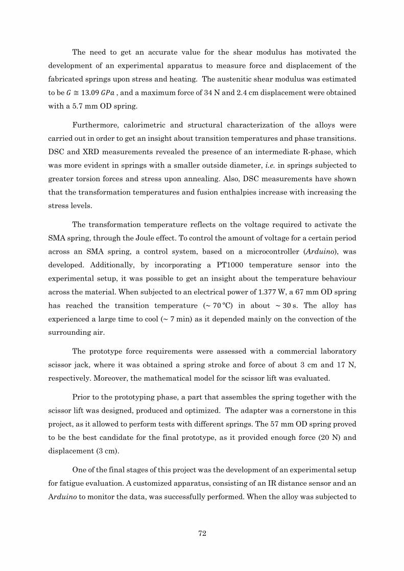
72
The need to get an accurate value for the shear modulus has motivated the development of an experimental apparatus to measure force and displacement of the fabricated springs upon stress and heating. The austenitic shear modulus was estimated
to be 𝐺𝐺 ≅ 13.09 𝐺𝐺𝐺𝐺𝐺𝐺 , and a maximum force of 34 N and 2.4 cm displacement were obtained with a 5.7 mm OD spring.
Furthermore, calorimetric and structural characterization of the alloys were carried out in order to get an insight about transition temperatures and phase transitions. DSC and XRD measurements revealed the presence of an intermediate R-phase, which was more evident in springs with a smaller outside diameter, i.e. in springs subjected to greater torsion forces and stress upon annealing. Also, DSC measurements have shown that the transformation temperatures and fusion enthalpies increase with increasing the stress levels.
The transformation temperature reflects on the voltage required to activate the SMA spring, through the Joule effect. To control the amount of voltage for a certain period across an SMA spring, a control system, based on a microcontroller (Arduino), was developed. Additionally, by incorporating a PT1000 temperature sensor into the experimental setup, it was possible to get an insight about the temperature behaviour across the material. When subjected to an electrical power of 1.377 W, a 67 mm OD spring has reached the transition temperature (∼ 70 ºC) in about ∼ 30 s. The alloy has experienced a large time to cool (∼ 7 min) as it depended mainly on the convection of the surrounding air.
The prototype force requirements were assessed with a commercial laboratory scissor jack, where it was obtained a spring stroke and force of about 3 cm and 17 N, respectively. Moreover, the mathematical model for the scissor lift was evaluated.
Prior to the prototyping phase, a part that assembles the spring together with the scissor lift was designed, produced and optimized. The adapter was a cornerstone in this project, as it allowed to perform tests with different springs. The 57 mm OD spring proved to be the best candidate for the final prototype, as it provided enough force (20 N) and displacement (3 cm).
One of the final stages of this project was the development of an experimental setup for fatigue evaluation. A customized apparatus, consisting of an IR distance sensor and an Arduino to monitor the data, was successfully performed. When the alloy was subjected to

73
strains of about 10%, it was shown that his displacement under actuation has decreased by performing consecutive cycles ON-OFF.
Finally, a prototype of a scissor lift was designed and fabricated. The prototype was lightweight, compact, and made of acrylic. A load of 400 g was successfully lifted by means of an SMA spring with 1 cm long and an outside diameter of 57 mm. Thus, the use of the shape memory behaviour in a lift actuation mechanism was successfully demonstrated.
7.2 Future Work Considering the results achieved during this project, it is possible to trace new guidelines for future improvements.
The post-treatments of the alloy are a determinant factor on the performance of the actuator, as it was demonstrated by the shift of the transition temperatures for different springs. Therefore, regarding the annealing stage, experimental trials with different temperatures and periods should carefully performed. Also, it would be interesting to investigate the influence of stress and thermal ageing on the final performance of the material. Moreover, it would be useful to perform more fatigue tests to understand the influence of distinct strains in the alloy’s life cycle.
In this work the control system consisted of an electronic device that allows to control the time during which the spring would be actuated. It would be much more valuable to control the temperature of the spring instead. The integration of a temperature sensor into the system would allow to monitor and to adjust, in real time, the voltage applied to the spring. Hence, one could define a threshold temperature so that the spring does not overheat. Also, one of the main limitations of SMA actuation is the cooling process. Design and implementation of an efficient cooling system should be performed. From the user point of view, another upgrade would be controlling the lift through a smartphone. This can be achieved by combining a bluetooth or wi-fi module with the Arduino.
With regard to the lift, the actuation mechanism was restricted to one spring. By distributing the weight through different springs, one could lift heavier objects. The developed adapter allows to integrate up to 3 springs, so evaluation tests with 2 and 3 springs should be performed.

74
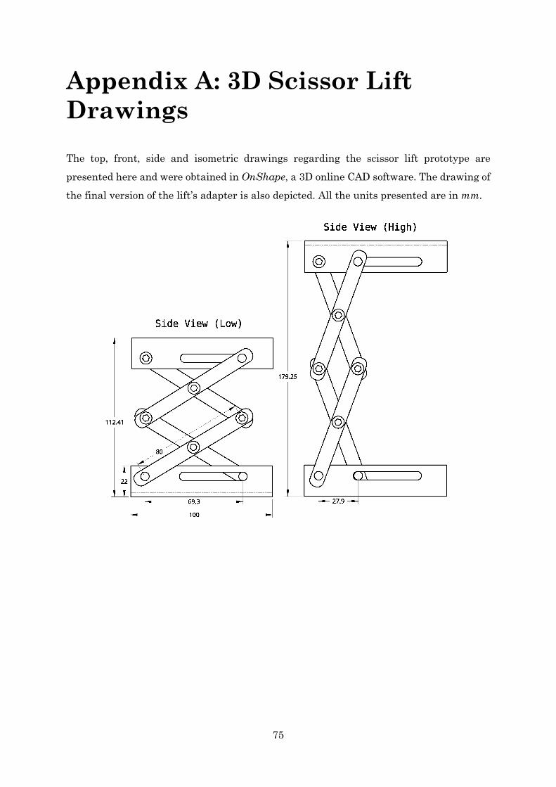
75
Appendix A: 3D Scissor Lift Drawings The top, front, side and isometric drawings regarding the scissor lift prototype are presented here and were obtained in OnShape, a 3D online CAD software. The drawing of the final version of the lift’s adapter is also depicted. All the units presented are in mm.
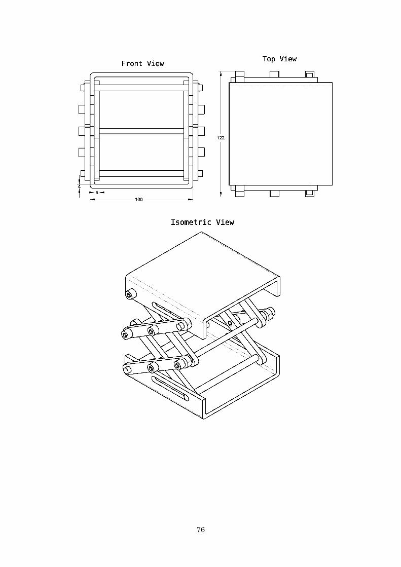
76
77

78

79
Appendix B: SMA Springs Spreadsheet Based on the equations regarding the design of SMA springs (section 2.3), a spreadsheet was developed in Microsoft Excel.
SPRING SPREADSHEETcm/ºC/GPa/g SI
d - Wire Diameter 0,1 0,001T - Activation Temperature 80 353,16OD - Spring Outer Diameter 0,57 0,0057Ls -Solid Spring Length (pos-annealing) 1 0,01La - Free Spring Length with load (austenite) 2 0,02ε max - maximum strain 3,00% 3,00%
G - Shear Modulus 13,09 1,31E+10D - Spring Average Diameter 0,47 0,0047C -Spring Index 4,7 4,7N - Number of Coils 10 10δ - maximum elongation (unloaded and in martensite) 1,80 0,0180
Lm - Maximum Length of the Spring (Limit) 2,80 0,03dx - Spring Effective Displacement 0,80 0,01K (N/m) - Spring Constant (Austenite) 1541,12F (N) - Actuation Force 15,41Massa - Mass Supported 1570,97 1,57Dv - Diameter of the manufacturing screw thread 0,37 0,0037Lwire - Length of wire required 14,77 0,15
Input
Spring Parameters
Output

80
81
Bibliography [1] M. Ashby, “Materials-a brief history,” Philos. Mag. Lett., vol. 88, no. 9–10, pp. 749–
755, 2008.
[2] P. Ghosh, A. Rao, and A. R. Srinivasa, “Design of multi-state and smart-bias components using shape memory alloy and shape memory polymer composites,” Mater. Des., vol. 44, pp. 164–171, 2013.
[3] D. C. Lagoudas, Shape Memory Alloys, vol. 1. 2008.
[4] K. Otsuka and C. M. Wayman, “Shape memory materials,” p. 147, 1999.
[5] A. Rao, A. R. Srinivasa, and J. N. Reddy, Design of Shape Memory Alloy (SMA)
Actuators. 2015.
[6] W. D. Callister, “Materials science and engineering: An introduction (2nd edition),” Mater. Des., vol. 12, no. 1, p. 59, 1991.
[7] A. Ölander, “An electrochemical investigation of solid cadmium-gold alloys,” J. Am.
Chem. Soc., vol. 54, no. 10, pp. 3819–3833, 1932.
[8] J. Mohd Jani, M. Leary, A. Subic, and M. A. Gibson, “A review of shape memory alloy research, applications and opportunities,” Mater. Des., vol. 56, pp. 1078–1113, 2014.
[9] M. Elahinia, “Shape Memory and Superelastic Alloys,” Book. 2014.
[10] J. M. Walker, C. Haberland, M. Taheri Andani, H. E. Karaca, D. Dean, and M. Elahinia, “Process development and characterization of additively manufactured nickel-titanium shape memory parts,” J. Intell. Mater. Syst. Struct., 2016.
[11] C. Haberland, M. Elahinia, J. M. Walker, H. Meier, and J. Frenzel, “On the development of high quality NiTi shape memory and pseudoelastic parts by additive manufacturing,” Smart Mater. Struct., 2014.
[12] H. Tan and M. H. Elahinia, “A nonlinear model for ferromagnetic shape memory alloy actuators,” Commun. Nonlinear Sci. Numer. Simul., 2008.
[13] I. Gibson, D. W. Rosen, and B. Stucker, “Additive Manufacturing Technologies,” Addit. Manuf. Technol. Rapid Prototyp. to Direct Digit. Manuf., 2010.
82
[14] L. C. Chang and T. A. Read, “Plastic Deformation and Diffusionless Phase Changes in Metals - The Gold-Cadmium Beta-Phase,” Trans. Am. Inst. Min. Metall. Eng., vol. 191, no. 1, pp. 47–52, 1951.
[15] P. Shayanfard, M. Kadkhodaei, and S. Safaee, “Proposition of R-phase transformation strip in the phase diagram of Ni-Ti shape memory alloy using electromechanical experiments,” 2017.
[16] Z. H. Wu, D. Vokoun, C. C. Leu, and C. T. Hu, “A Two-Way Shape Memory Study on Ni-Rich NiTi Shape Memory Alloy by Combination of the All-Round Treatment and the R-Phase Transformation,” vol. 74, pp. 0–9, 2017.
[17] M. H. Elahinia, Shape memory alloy actuators : design, fabrication, and
experimental evaluation. 2015.
[18] C. M. Wayman, “Shape memory and related phenomena,” Prog. Mater. Sci., vol. 36, no. C, pp. 203–224, 1992.
[19] W. M. Huang, Z. Ding, C. C. Wang, J. Wei, Y. Zhao, and H. Purnawali, “Shape memory materials,” Mater. Today, vol. 13, no. 7–8, pp. 54–61, 2010.
[20] W. J. Buehler, J. V Gilfrich, and R. C. Wiley, “Effect of LowTemperature Phase Changes on the Mechanical Properties of Alloys near Composition TiNi,” vol. 1475, pp. 28–31, 1963.
[21] Z. Zhang, J. Frenzel, K. Neuking, and G. Eggeler, “Vacuum Induction Melting of Ternary NiTiX (X=Cu, Fe, Hf, Zr) Shape Memory Alloys Using Graphite Crucibles,” Mater. Trans., vol. 47, no. 3, pp. 661–669, 2006.
[22] J. Khalil-allafi, A. Dlouhy, and G. Eggeler, “Ni 4 Ti 3 -precipitation during aging of NiTi shape memory alloys and its influence on martensitic phase transformations,” vol. 50, pp. 4255–4274, 2002.
[23] A. Radi, M. R. Etminanfar, S. Pourbabak, and D. Schryvers, “Influence of stress aging process on variants of nano-Ni4Ti3 precipitates and martensitic transformation temperatures in NiTi shape memory alloy,” Mater. Des., no. 2017, 2018.
[24] M. Kök, F. Daʇdelen, A. Aydoʇdu, and Y. Aydoʇdu, “The change of transformation temperature on NiTi shape memory alloy by pressure and thermal ageing,” J. Phys.
Conf. Ser., vol. 667, no. 1, 2016.
83
[25] M. H. Elahinia, M. Hashemi, M. Tabesh, and S. B. Bhaduri, “Manufacturing and processing of NiTi implants: A review,” Prog. Mater. Sci., vol. 57, no. 5, pp. 911–946, 2012.
[26] E. Obropta, D. N. Low, C. Link, B. Holschuh, and D. Newman, “Low Spring Index NiTi Coil Actuators,” pp. 1–14, 2014.
[27] J. Black, Black, Jonathan-Biological Performance of Materials _ Fundamentals of
Biocompatibility, Fourth Edition-CRC Press (2005).pdf. 2005.
[28] J. N. Kudva, “Overview of the DARPA smart wing project,” Journal of Intelligent
Material Systems and Structures, vol. 15, no. 4. pp. 261–267, 2004.
[29] D. J. Hartl and D. C. Lagoudas, “Aerospace applications of shape memory alloys,” Proc. Inst. Mech. Eng. Part G J. Aerosp. Eng., vol. 221, no. 4, pp. 535–552, 2007.
[30] J. M. Jani, M. Leary, and A. Subic, “Shape Memory Alloys in Automotive Applications,” Appl. Mech. Mater., vol. 663, pp. 248–253, 2014.
[31] D. Stoeckel, “Shape memory actuators for automotive applications,” Mater. Des., vol. 11, no. 6, pp. 302–307, 1990.
[32] A. Hadi, A. Yousefi-Koma, M. M. Moghaddam, M. Elahinia, and A. Ghazavi, “Developing a novel SMA-actuated robotic module,” Sensors Actuators, A Phys., 2010.
[33] M. Nematollahi, R. Mehrabi, M. A. Callejas, H. Elahinia, and M. Elahinia, “A two-way architectural actuator using NiTi SE wire and SME spring,” in Proceedings of
SPIE - The International Society for Optical Engineering, 2018.
[34] M. Kheirikhah, S. Rabiee, and M. Edalat, “A Review of Shape Memory Alloy Actuators in Robotics,” Rob. 2010 Robot Soccer World Cup XIV SE - 18, vol. 6556, no. September, pp. 206–217, 2011.
[35] C. Pfeiffer, K. DeLaurentis, and C. Mavroidis, “Shape memory alloy actuated robot prostheses: initial experiments,” Proc. 1999 IEEE Int. Conf. Robot. Autom. (Cat.
No.99CH36288C), vol. 3, pp. 2385–2391, 1999.
[36] Y. Tadesse, D. Hong, and S. Priya, “Twelve Degree of Freedom Baby Humanoid Head Using Shape Memory Alloy Actuators,” J. Mech. Robot., vol. 3, no. 1, p. 011008, 2011.
84
[37] A. Saxena, “Deriving a Generalized , Actuator Position-Independent Expression for the Force Output of a Scissor Lift,” pp. 1–18, 2016.
[38] H. M. Spackman, “Mathematical Analysis of Scissor Lifts,” 1989.
[39] B. Holschuh and D. Newman, “Low spring index, large displacement Shape Memory Alloy (SMA) coil actuators for use in macro- and micro-systems,” Spie Moems-Mems, p. 897505, 2014.
[40] M. H. Elahinia, M. Hashemi, M. Tabesh, and S. B. Bhaduri, “Manufacturing and processing of NiTi implants: A review,” Progress in Materials Science. 2012.
[41] J. Otubo, O. D. Rigo, C. M. Neto, and P. R. Mei, “The effects of vacuum induction melting and electron beam melting techniques on the purity of NiTi shape memory alloys,” Mater. Sci. Eng. A, 2006.
[42] J. Frenzel, Z. Zhang, K. Neuking, and G. Eggeler, “High quality vacuum induction melting of small quantities of NiTi shape memory alloys in graphite crucibles,” J.
Alloys Compd., 2004.
[43] S. Saedi, A. S. Turabi, M. T. Andani, N. S. Moghaddam, M. Elahinia, and H. E. Karaca, “Texture, aging, and superelasticity of selective laser melting fabricated Ni-rich NiTi alloys,” Mater. Sci. Eng. A, 2017.
[44] M. Taheri Andani et al., “Mechanical and shape memory properties of porous Ni50.1Ti49.9alloys manufactured by selective laser melting,” J. Mech. Behav.
Biomed. Mater., 2017.
[45] A. Foroozmehr, A. Kermanpur, F. Ashrafizadeh, and Y. Kabiri, “Investigating microstructural evolution during homogenization of the equiatomic NiTi shape memory alloy produced by vacuum arc remelting,” Mater. Sci. Eng. A, vol. 528, no. 27, pp. 7952–7955, 2011.
[46] P. Gill, T. T. Moghadam, and B. Ranjbar, “Differential scanning calorimetry techniques: applications in biology and nanoscience.,” J. Biomol. Tech., vol. 21, no. 4, pp. 167–93, 2010.
[47] H. K. D. H. Bhadeshia, “Differential Scanning Calorimetry.”
[48] PerkinElmer and Inc, “Differential Scanning Calorimetry (DSC) PerkinElmer’s DSC Family A Beginner’s Guide,” Faq, pp. 1–7, 2013.
85
[49] J. Rodríguez-Aseguinolaza, I. Ruiz-Larrea, M. L. Nó, A. López-Echarri, and J. San Juan, “The influence of partial cycling on the martensitic transformation kinetics in shape memory alloys,” Intermetallics, vol. 17, no. 9, pp. 749–752, 2009.
[50] B. D. Cullity and S. R. Stock, “Elements of X-ray diffraction, 3rd edition,” Prentice
Hall, 2001.
[51] N. Waeselmann, “Structural transformations in complex perovskite-type relaxor and relaxor-based ferroelectrics at high pressures and temperatures,” Hamburg University, 2012.
[52] “Measuring temperature: Platinum Resistance thermometers.” [Online]. Available: http://www.code10.info/index.php%3Foption%3Dcom_content%26view%3Darticle%26id%3D82:measuring-temperature-platinum-resistance-thermometers%26catid%3D60:temperature%26Itemid%3D83. [Accessed: 24-Sep-2018].