Embed Size (px)
Citation preview
Smart Manufacturing Connectivity
for Brown-field Sensors Testbed –
Initial Deployment –
Report after Completion of Phase I An Industrial Internet Consortium Results White Paper
IIC:WHT:IN27:V1.0:PB:20181023
Dr. Michael Hilgner (TE Connectivity)
Erich Karl Clauer (SAP)
Smart Manufacturing Connectivity for Brown-field Sensors Testbed – Completion of Phase I
IIC:WHT:IN27:V1.0:PB:20181023 - 2 -
This white paper provides an overview of the accomplishments of phase I of the “Smart Manu-
facturing Connectivity for Brown-field Sensors Testbed.” The testbed addresses the discrete
manufacturing domain where Programmable Logic Controllers (PLCs) typically govern local
control loops of sensors and actuators that are either directly connected to a PLC or via an
Input/Output module, an I/O module. The testbed focuses on a brown-field scenario where IO-
Link sensors are connected to an elderly PLC through an IO-Link master gateway, which is a
special active I/O module capable of mastering IO-Link devices. IO-Link is a digital interface that
enables a bidirectional data exchange with sensors and actuators.
The testbed comprises the development of a retrofittable hardware that is intended to replace
an existing I/O module and establishes a communication channel towards higher-level IT
systems, in addition to the channel used for the data exchange with the PLC. As this hardware
delivers data from a common source, namely a set of sensors, to two recipients, the higher-
level IT system and the PLC, it is called the “Y-Gateway.” The data exchanged through the two
communication paths are however quite different: The PLC is only provided with the data
required to run the original control task, whereas more comprehensive information is delivered
through the additional path to enable added value services. So, the (elderly) PLC is not
burdened with data processing beyond carrying out the functions for which it was once
selected and programmed.
The testbed further encompasses the definition and implementation of a consistent mapping
from IO-Link to OPC Unified Architecture (OPC UA). The result is an OPC UA device model with
standardized semantics that is used by the server-client-based data exchange between the Y-
Gateway and the IT system to facilitate the easy integration of the sensor data within the IT
system’s data base. Using OPC UA over TCP/IP for the additional channel established by the Y-
Gateway not only guarantees the semantic interoperability but also assures a secure
connection through OPC UA’s proven security mechanisms.
The testbed finally includes the implementation of a usage scenario that increases the overall
equipment effectiveness of a manufacturing process step by collecting data on consumed
resources by a set of IO-Link sensors and providing those to SAP Manufacturing Integration &
Intelligence (SAP MII) or SAP Cloud via the additional communication path that allows for the
implementation of added value service at the enterprise level.
The white paper describes the proposed solutions’ elements and fundamental capabilities and
the technical details have been made available to the Industrial Internet Consortium (IIC)
community via more comprehensive deliverables, such as a high-level description of the IO-
Link/OPC UA mapping, a report on the Y-Gateway’s endpoint security threat analysis, a
specification to measure the latency of the real-time path through the Y-Gateway, a description
of OPC UA’s communication security mechanisms and a report on the impact of applying
security measures on OPC UA’s performance.
Smart Manufacturing Connectivity for Brown-field Sensors Testbed – Completion of Phase I
IIC:WHT:IN27:V1.0:PB:20181023 - 3 -
This set of deliverables, including this white paper, documents the technical feasibility of the
testbed’s approach and shows the benefits for manufacturing operators, namely that
retrofitting a brown-field facility with just a few sensors and connecting them to the
appropriate platform solution provides quick insights into potential improvements and
optimization requirements.
INTRODUCTION INTO THE TESTBED
The Smart Manufacturing Connectivity for Brown-field Sensors Testbed is a joint effort of IIC
members TE Connectivity, a world leader in connectivity and sensors, and SAP, a world leader in
enterprise applications in terms of software and software-related service revenue. Additional
collaboration partners are ifm, a worldwide leader in sensors, controllers and systems for
automation and the OPC Foundation, the organization defining the industrial interoperability
standard OPC UA. The IIC Steering Committee approved the testbed in April 2016. Public
information is available on a dedicated web page under www.iiconsortium.org.
This testbed addresses the discrete manufacturing domain, traditionally characterized by a
strict hierarchical structure, referred to as the “Automation Pyramid.” At the control level of the
pyramid, PLCs manage the real-time sub-systems, including sensors and actuators, and provide
the connection to the enterprise IT systems. In this structure, any data generated by a sensor
passes through the PLC. Whereas planning a green-field installation generally considers the
capability of processing a high volume of data required by advanced (cloud-based) analytics for
the selection of the PLCs, in brown-field facilities, the PLCs are often capable of running the
automation sequence only.
Smart Manufacturing Connectivity for Brown-field Sensors Testbed – Completion of Phase I
IIC:WHT:IN27:V1.0:PB:20181023 - 4 -
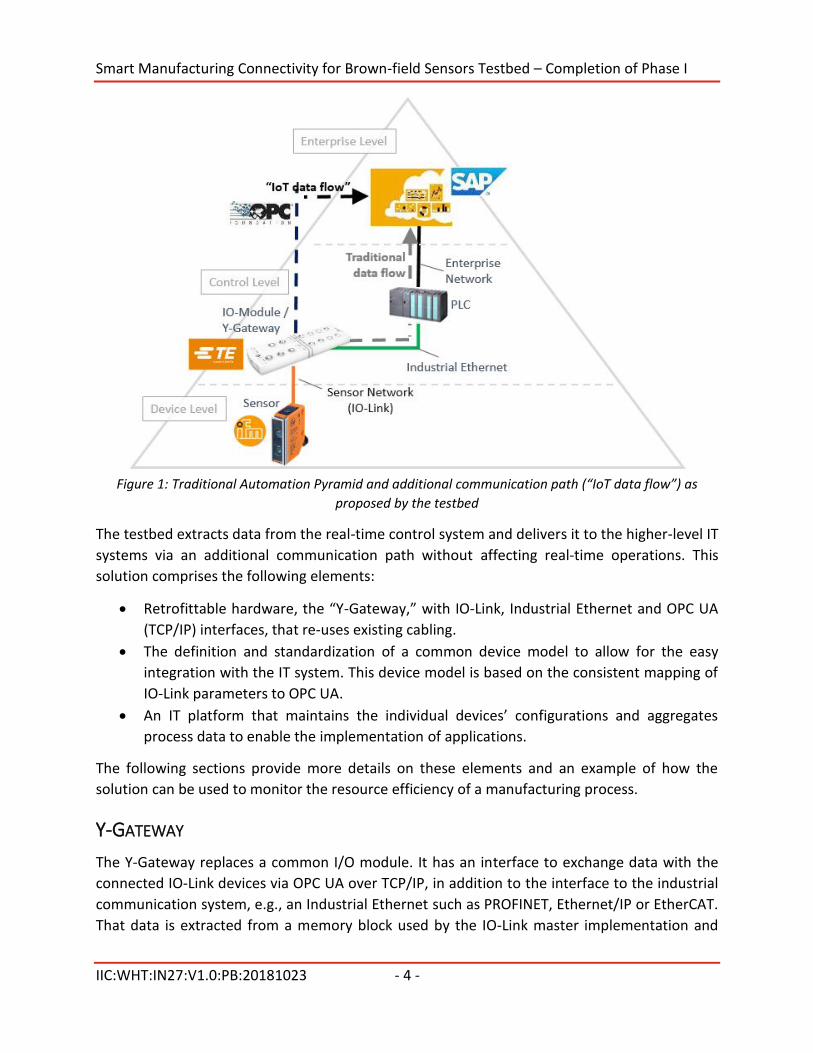
Figure 1: Traditional Automation Pyramid and additional communication path (“IoT data flow”) as
proposed by the testbed
The testbed extracts data from the real-time control system and delivers it to the higher-level IT
systems via an additional communication path without affecting real-time operations. This
solution comprises the following elements:
Retrofittable hardware, the “Y-Gateway,” with IO-Link, Industrial Ethernet and OPC UA
(TCP/IP) interfaces, that re-uses existing cabling.
The definition and standardization of a common device model to allow for the easy
integration with the IT system. This device model is based on the consistent mapping of
IO-Link parameters to OPC UA.
An IT platform that maintains the individual devices’ configurations and aggregates
process data to enable the implementation of applications.
The following sections provide more details on these elements and an example of how the
solution can be used to monitor the resource efficiency of a manufacturing process.
Y-GATEWAY
The Y-Gateway replaces a common I/O module. It has an interface to exchange data with the
connected IO-Link devices via OPC UA over TCP/IP, in addition to the interface to the industrial
communication system, e.g., an Industrial Ethernet such as PROFINET, Ethernet/IP or EtherCAT.
That data is extracted from a memory block used by the IO-Link master implementation and
Smart Manufacturing Connectivity for Brown-field Sensors Testbed – Completion of Phase I
IIC:WHT:IN27:V1.0:PB:20181023 - 5 -
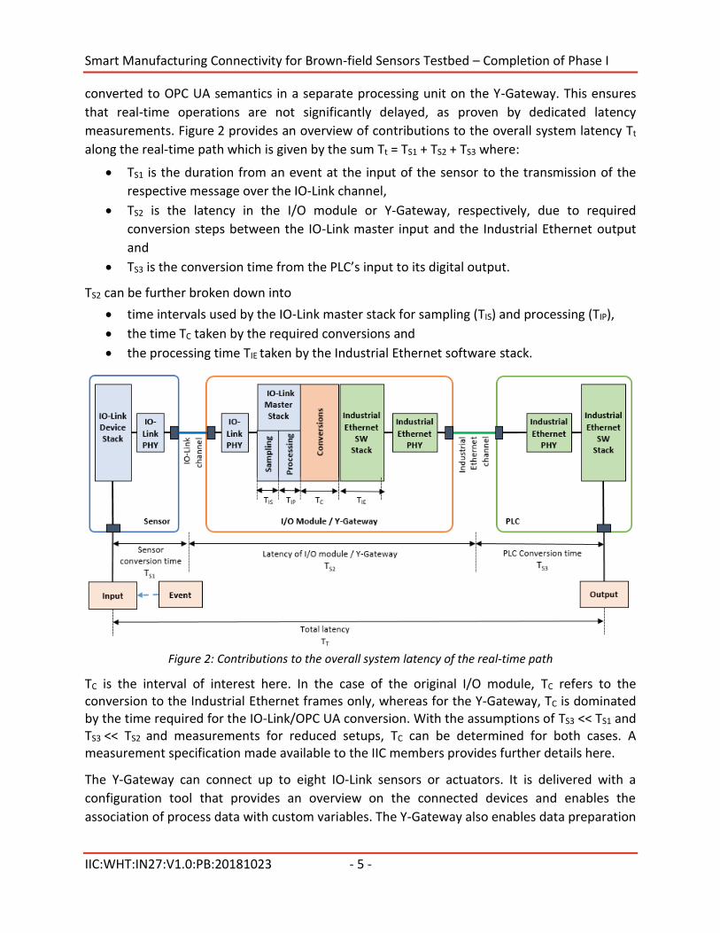
converted to OPC UA semantics in a separate processing unit on the Y-Gateway. This ensures
that real-time operations are not significantly delayed, as proven by dedicated latency
measurements. Figure 2 provides an overview of contributions to the overall system latency Tt
along the real-time path which is given by the sum Tt = TS1 + TS2 + TS3 where:
TS1 is the duration from an event at the input of the sensor to the transmission of the
respective message over the IO-Link channel,
TS2 is the latency in the I/O module or Y-Gateway, respectively, due to required
conversion steps between the IO-Link master input and the Industrial Ethernet output
and
TS3 is the conversion time from the PLC’s input to its digital output.
TS2 can be further broken down into
time intervals used by the IO-Link master stack for sampling (TIS) and processing (TIP),
the time TC taken by the required conversions and
the processing time TIE taken by the Industrial Ethernet software stack.
Figure 2: Contributions to the overall system latency of the real-time path
TC is the interval of interest here. In the case of the original I/O module, TC refers to the conversion to the Industrial Ethernet frames only, whereas for the Y-Gateway, TC is dominated by the time required for the IO-Link/OPC UA conversion. With the assumptions of TS3 << TS1 and TS3 << TS2 and measurements for reduced setups, TC can be determined for both cases. A measurement specification made available to the IIC members provides further details here.
The Y-Gateway can connect up to eight IO-Link sensors or actuators. It is delivered with a
configuration tool that provides an overview on the connected devices and enables the
association of process data with custom variables. The Y-Gateway also enables data preparation
Smart Manufacturing Connectivity for Brown-field Sensors Testbed – Completion of Phase I
IIC:WHT:IN27:V1.0:PB:20181023 - 6 -
and combination of data from several IO-Link sensors prior to the delivery to the connected IT
system.
IO-LINK
The IO-Link technology provides a serial, bi-directional, point-to-point interface for the
connection of sensors and actuators to a control system, including a 24V power supply. There is
a set of IO-Link specifications published by the IO-Link Community. The fundamental IO-Link
specification is adopted as International Standard IEC 61131-9 (Programmable controllers—Part
9: Single-drop digital communication interface for small sensors and actuators (SDCI)) and
hence allows consistent integration with common industrial communication and automation
systems.
IO-Link is developed and promoted by the IO-Link Community (www.io-link.com). Testbed
partners TE Connectivity and ifm are members of that community. The IO-Link System
Description made available on www.io-link.com/en/Download/Download provides an overview
of the technology. An IO-Link system consists of the following basic components:
IO-Link devices (e.g., sensors, RFID readers, valves, motor starters and IO modules),
an IO-Link master that establishes the connection between the IO-Link devices and the
automation system, where one IO-Link device is connected to one port of the master
(point-to-point) and
unshielded (3- or 5-conductor) cables of up to 20 m to connect the devices and the
master.
According to the IO-Link Specification v1.1, IO-Link supports the modes with transmission rates
of 230.4, 38.4 and 4.8 kbaud. The response time of the system depends on the cycle times of
the devices. The minimum cycle time is specified for each device in the respective device
description (the IO Device Description or IODD).
Four types of data are communicated via an IO-Link Interface:
(cyclic) process data with a maximum of 32 bytes,
(cyclic) status data indicating the integrity of the process data (mostly transmitted
together with the process data),
(acyclic) device data providing parameters, identification or diagnostic information on a
device at the request of the IO-Link master and
(acyclic) events, such as error messages and maintenance warnings (e.g., in case of
overheating).
Smart Manufacturing Connectivity for Brown-field Sensors Testbed – Completion of Phase I
IIC:WHT:IN27:V1.0:PB:20181023 - 7 -
Dedicated tools provided by the IO-Link master suppliers are used for configuration purposes.
Each IO-Link device is delivered with a set of configuration files with the device’s IODD. The
configuration tool is fed with the IODDs of the connected devices and may then be used to:
assign the devices to the ports of the master,
map IO addresses of the individual ports’ process data to master addresses and
assign parameters of the IO-Link devices.
The IODD is an electronic device description available for each IO-Link device and contains a
variety of information for the system integration. The structure of the IODD is based on an
International Standard (ISO 15745-1 Industrial automation systems and integration—Open
systems application integration framework—Part 1: Generic reference description) and is thus
identical for all devices of all manufacturers.
The IODD is explained in detail in the IO Device Description Specification that is also available
from www.io-link.com/en/Download/Download together with the IODD Checker tool that may
be used to verify the integrity of an IODD.
The properties of a device are specified within the following XML files:
the main IODD file contains information about the identification of the device,
communication characteristics, parameters, process data and diagnosis data and
the standard definition files contain the definition of standardized variables, error types
and events as well as the definitions of all available unit codes.
OPC UNIFIED ARCHITECTURE
OPC UA, also published as IEC 62541, allows for the exchange of information models of any
complexity—both instances and types (metadata)—and so enables semantic interoperability.
OPC UA is designed to support a wide range of systems, ranging from PLCs in production to
enterprise servers. These systems are characterized by their diversity in terms of size,
performance, platforms and functional capabilities.
The following functionalities were specified for OPC UA, forming the basis of the OPC UA
information-modeling framework:
Transport for the data exchange mechanisms between OPC UA applications. Different transport
protocols exist for different requirements.
The metamodel specifies the rules and basic components for publishing an information model
via OPC UA. It also includes various basic nodes and basic types.
Services constitute the interface between a server as information provider and clients as
consumer of this information. OPC UA defines the services required to navigate through the
address space, read or write variables and subscribing for data modifications and events.
Smart Manufacturing Connectivity for Brown-field Sensors Testbed – Completion of Phase I
IIC:WHT:IN27:V1.0:PB:20181023 - 8 -
Service requests and responses are transmitted through exchange of messages between clients
and servers.
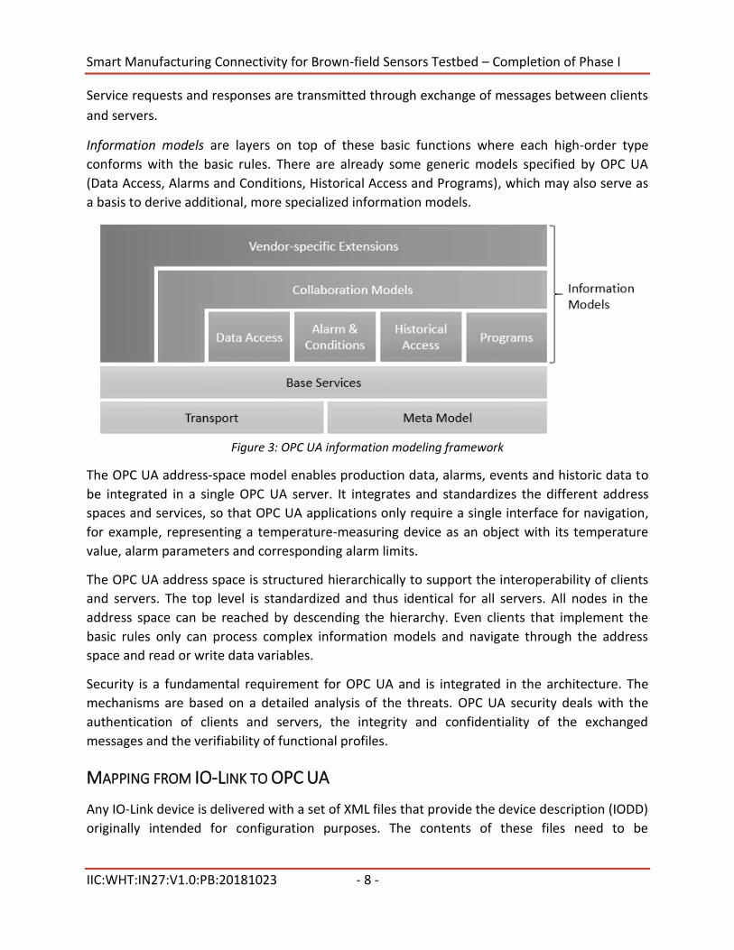
Information models are layers on top of these basic functions where each high-order type
conforms with the basic rules. There are already some generic models specified by OPC UA
(Data Access, Alarms and Conditions, Historical Access and Programs), which may also serve as
a basis to derive additional, more specialized information models.
Figure 3: OPC UA information modeling framework
The OPC UA address-space model enables production data, alarms, events and historic data to
be integrated in a single OPC UA server. It integrates and standardizes the different address
spaces and services, so that OPC UA applications only require a single interface for navigation,
for example, representing a temperature-measuring device as an object with its temperature
value, alarm parameters and corresponding alarm limits.
The OPC UA address space is structured hierarchically to support the interoperability of clients
and servers. The top level is standardized and thus identical for all servers. All nodes in the
address space can be reached by descending the hierarchy. Even clients that implement the
basic rules only can process complex information models and navigate through the address
space and read or write data variables.
Security is a fundamental requirement for OPC UA and is integrated in the architecture. The
mechanisms are based on a detailed analysis of the threats. OPC UA security deals with the
authentication of clients and servers, the integrity and confidentiality of the exchanged
messages and the verifiability of functional profiles.
MAPPING FROM IO-LINK TO OPC UA
Any IO-Link device is delivered with a set of XML files that provide the device description (IODD)
originally intended for configuration purposes. The contents of these files need to be
Smart Manufacturing Connectivity for Brown-field Sensors Testbed – Completion of Phase I
IIC:WHT:IN27:V1.0:PB:20181023 - 9 -
standardized and converted to OPC UA data structures (i.e., specific extensions are added to
the basic OPC UA information models).
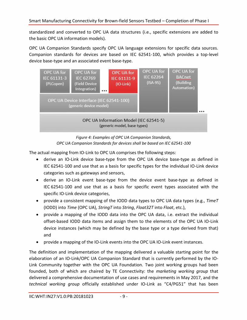
OPC UA Companion Standards specify OPC UA language extensions for specific data sources.
Companion standards for devices are based on IEC 62541-100, which provides a top-level
device base-type and an associated event base-type.
Figure 4: Examples of OPC UA Companion Standards,
OPC UA Companion Standards for devices shall be based on IEC 62541-100
The actual mapping from IO-Link to OPC UA comprises the following steps:
derive an IO-Link device base-type from the OPC UA device base-type as defined in
IEC 62541-100 and use that as a basis for specific types for the individual IO-Link device
categories such as gateways and sensors,
derive an IO-Link event base-type from the device event base-type as defined in
IEC 62541-100 and use that as a basis for specific event types associated with the
specific IO-Link device categories,
provide a consistent mapping of the IODD data types to OPC UA data types (e.g., TimeT
(IODD) into Time (OPC UA), StringT into String, Float32T into Float, etc.),
provide a mapping of the IODD data into the OPC UA data, i.e. extract the individual
offset-based IODD data items and assign them to the elements of the OPC UA IO-Link
device instances (which may be defined by the base type or a type derived from that)
and
provide a mapping of the IO-Link events into the OPC UA IO-Link event instances.
The definition and implementation of the mapping delivered a valuable starting point for the
elaboration of an IO-Link/OPC UA Companion Standard that is currently performed by the IO-
Link Community together with the OPC UA Foundation. Two joint working groups had been
founded, both of which are chaired by TE Connectivity: the marketing working group that
delivered a comprehensive documentation of use cases and requirements in May 2017, and the
technical working group officially established under IO-Link as “C4/PG51” that has been
Smart Manufacturing Connectivity for Brown-field Sensors Testbed – Completion of Phase I
IIC:WHT:IN27:V1.0:PB:20181023 - 10 -
working on the specification since June 2016. The final review by the IO-Link Community was
initiated in September 2018, and it should be published by the end of 2018. With the
implementation of the additions and modifications required to satisfy all requirements of the
specification, the testbed will also serve as a reference implementation, the availability of
which is a prerequisite for the adoption by the OPC Foundation.
PLATFORM OPTIONS
For communication with the Enterprise or Cloud Platform Level, SAP Plant Connectivity (PCo)
serves as an OPC Client. In addition to its role as OPC UA client that is used in this testbed, PCo
supports many common communication protocols used for data exchange in IIoT applications
(e.g., MQTT). PCo is designed to establish the connection to various platform solutions each of
which is suitable for a wide range of applications with diverse focuses.
Within this testbed, two platform solutions were connected and associated data models were
implemented:
SAP Manufacturing Integration & Intelligence (MII) is an SAP application for
synchronizing manufacturing operations with back-office business processes. In many
use cases it is configured as a data hub between SAP ERP and operational applications,
such as a manufacturing execution system (MES) and provides analytics and workflow
tools for identifying problems in the production process and improving its performance.
SAP Cloud Platform is a platform-as-a-service developed by SAP SE for creating new
applications or extending existing applications in a secure cloud computing environment
managed by SAP. The SAP Cloud Platform integrates data and business processes.
Smart Manufacturing Connectivity for Brown-field Sensors Testbed – Completion of Phase I
IIC:WHT:IN27:V1.0:PB:20181023 - 11 -
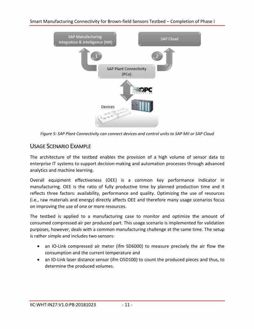
Figure 5: SAP Plant Connectivity can connect devices and control units to SAP MII or SAP Cloud
USAGE SCENARIO EXAMPLE
The architecture of the testbed enables the provision of a high volume of sensor data to
enterprise IT systems to support decision-making and automation processes through advanced
analytics and machine learning.
Overall equipment effectiveness (OEE) is a common key performance indicator in
manufacturing. OEE is the ratio of fully productive time by planned production time and it
reflects three factors: availability, performance and quality. Optimizing the use of resources
(i.e., raw materials and energy) directly affects OEE and therefore many usage scenarios focus
on improving the use of one or more resources.
The testbed is applied to a manufacturing case to monitor and optimize the amount of
consumed compressed air per produced part. This usage scenario is implemented for validation
purposes, however, deals with a common manufacturing challenge at the same time. The setup
is rather simple and includes two sensors:
an IO-Link compressed air meter (ifm SD6000) to measure precisely the air flow the
consumption and the current temperature and
an IO-Link laser distance sensor (ifm O5D100) to count the produced pieces and thus, to
determine the produced volumes.
Smart Manufacturing Connectivity for Brown-field Sensors Testbed – Completion of Phase I
IIC:WHT:IN27:V1.0:PB:20181023 - 12 -
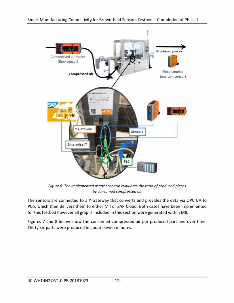
Figure 6: The implemented usage scenario evaluates the ratio of produced pieces
by consumed compressed air
The sensors are connected to a Y-Gateway that converts and provides the data via OPC UA to
PCo, which then delivers them to either MII or SAP Cloud. Both cases have been implemented
for this testbed however all graphs included in this section were generated within MII.
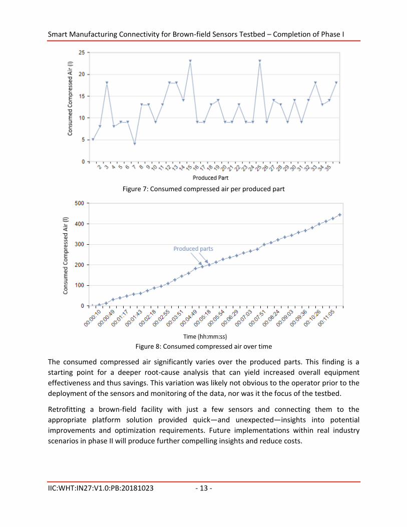
Figures 7 and 8 below show the consumed compressed air per produced part and over time.
Thirty-six parts were produced in about eleven minutes.
Smart Manufacturing Connectivity for Brown-field Sensors Testbed – Completion of Phase I
IIC:WHT:IN27:V1.0:PB:20181023 - 13 -
Figure 7: Consumed compressed air per produced part
Figure 8: Consumed compressed air over time
The consumed compressed air significantly varies over the produced parts. This finding is a
starting point for a deeper root-cause analysis that can yield increased overall equipment
effectiveness and thus savings. This variation was likely not obvious to the operator prior to the
deployment of the sensors and monitoring of the data, nor was it the focus of the testbed.
Retrofitting a brown-field facility with just a few sensors and connecting them to the
appropriate platform solution provided quick—and unexpected—insights into potential
improvements and optimization requirements. Future implementations within real industry
scenarios in phase II will produce further compelling insights and reduce costs.
Smart Manufacturing Connectivity for Brown-field Sensors Testbed – Completion of Phase I
IIC:WHT:IN27:V1.0:PB:20181023 - 14 -
AUTHORS AND LEGAL NOTICE
This document is a work product of the Industrial Internet Consortium Testbed Working Group.
It is authored by Dr. Michael Hilgner (TE Connectivity) and Erich Karl Clauer (SAP).
Technical Editor: Stephen Mellor (IIC staff) oversaw the process of organizing the contributions
of the above Authors into an integrated document.
Copyright © 2018 Industrial Internet Consortium, a program of the Object Management Group,
Inc. (“OMG”).
All copying, distribution and use are subject to the limited License, Permission, Disclaimer and
other terms stated in the Industrial Internet Consortium Use of Information – Terms, Conditions
& Notices, as posted at http://www.iiconsortium.org/legal/index.htm#use_info. If you do not
accept these Terms, you are not permitted to use the document.