Embed Size (px)
Citation preview
978-1-4244-2794-9/09/$25.00 ©2009 IEEE SMC 2009
Smart Home at a Finger Tip: OSGi-based MyHome
Hsuan-Yu Huang1, Wei-Chung Teng1, and Sheng-Luen Chung2
1Dept. of Computer Science and Information Engineering, 2Dept. of Electrical Engineering National Taiwan University of Science and Technology
Taipei, Taiwan Email: {M9615052, weichung, slchung}@mail.ntust.edu.tw
Abstract—This paper introduces MyHome, a framework of smart home by which household information is all at a finger tip. Through adopting Message Oriented Middleware (MOM) and Open Service Gateway Initiative (OSGi) technologies, MyHome offers reliable automatic operations, fault tolerant and configurable home automation, high extensibility and large scalability. In its design, MyHome system is composed of a residential gateway MyServer and Internet accessible GUI MyIcon and MyMobile. MyServer is used to provide services regarding home security, inventory tracking, facility management, GPS location recording and family care. Inherently an interactive and multitasking system driven by peripherals connected through wireless sensor networks, the overall MyServer architecture is designed with six core service modules operating on a MOM. Each of these modules is designed as an OSGi bundles and is implemented by a programming template utilizing event publish/subscribe messaging mechanism. To facilitate program demonstration, simulator and scenario editor are also developed. A successful implementation of the proposed MyServer is also demonstrated in an emulated home environ-ment where peripherals are connected through ZigBee wireless sensor network with data integrated into a database. With these clearly defined service modules and pertinent infrastructure to integrate household peripherals, this paper presents a practical approach to the implementation of a smart home.
Keywords—MyHome, smart home, MOM, OSGi
I. INTRODUCTION
Smart home concept illustrates a context aware environ-ment by which family members can easily access information and services like housekeeping, health care, security, etc. The high diversity of household services implies that a highly flexible and customizable architecture is necessary for a smart home system. The physical layer of a smart home system should support a wide range of household devices over hetero-geneous network environment via standard communication protocols. Open Service Gateway Initiative (OSGi) has been considered successful in providing a standard abstraction interface to smart home system developers [2][3]. However, a well-designed mechanism on the basis of OSGi is still crucial for developing, debugging, and correlating service modules that support various household applications.
This paper proposes OSGi-based MyHome, a fully designed and implemented smart home system that provides integrated user interface and an event-driven, multi-threaded service development platform. The first version of MyHome demonstrates a system design that supports full functionality of
dynamically appending, removing, configuring, and communicating with various kinds of home devices on the implemented four categories of services [5][6][7]. However, the physical layer was implemented by ad hoc code, and the six server modules are loosely bound by a messaging oriented middleware (MOM). After reworked these modules into OSGi bundles, MyHome gains all the advantages of an OSGi system, such as good extensibility to physical devices and support of multi-server communication. The Apache ActiveMQ [12] messaging system is adopted in the new MyHome system to keep server modules working in the same logic as their origin design. Having all server modules running on the same OSGi platform and communicate with each other over one standard mechanism, designers may create, update, and even alter server modules and configure the communication protocols between them without difficulty. This feature is crucial to smart home system because the context of services needs to be configurable and new technologies emerge soon in this field at least for the last decade.
Some newly implemented functions like recording location of mobile phone via GPS, measuring and managing blood pressure, and scenario editor are introduced in the following sections to demonstrate how new services can be implemented and supported easily under MyHome system architecture.
The remaining part of this paper is organized as follows: section 2 introduces the concepts and the categories of services MyHome system provides; section 3 illustrates the whole system design of MyHome including the residential gateway MyServer and the two remote GUIs: MyIcon and MyMobile; section 4 explains the actual behavior of MyHome system via an example scenario; section 5 gives conclusions and discusses possible future work.
II. SERVICES PROVIDED BY MYHOME
There are four categories of services MyHome intends to provide: health, security, butler, and family care.
1) Health: MyServer may have physical connection with health care devices which measure physiological information like heart rate and blood pressure. On the other hand, MyIcon provides necessary GUI for the measuring process and for data representation.
2) Security: MyHome system has security sensors centrally managed by MyServer. Feedback from various sensors is collected by serial line or by Zigbee wireless communication. When one or more security sensors are
Proceedings of the 2009 IEEE International Conference on Systems, Man, and CyberneticsSan Antonio, TX, USA - October 2009
978-1-4244-2794-9/09/$25.00 ©2009 IEEE4577
SMC 2009
triggered, MyHome try to notify family members via MyIcon, MyMobile, e-mail, or short message.
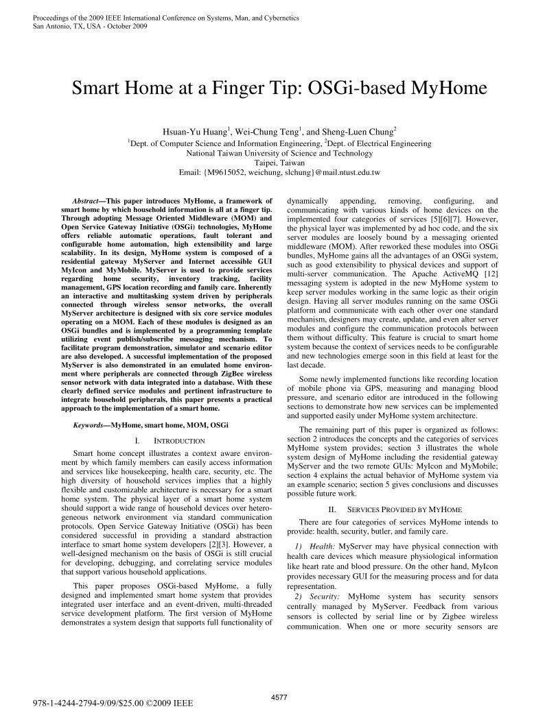
3) Butler: MyHome system utilizes image recognition technology to record data on the electricity meter, gas meter, and others. These records help family members to monitor and analyze the status of energy consumption at home. Further-more, butler service also provides inventory information by adopting RFID technology [9]. Home members can check the inventory of refrigerator, wardrobe, etc. through the remote GUI as shown in Fig. 1.
4) Family: MyHome system uses image processing technologies to build up person orientation recognition function, and records the entering time and out-of-home time of family members in database for remote accessing. When queried, MyHome is able to dynamically show positions of indoor family members on a simulated 2D map, or GPS locations of out-of-home members as shown in Fig. 1.
Figure 1. Screenshots of services via MyMobile
III. DESIGN OF THE OSGI-BASED MYHOME
A. Integration Platform
Middleware technologies provide a standard way to connect home gateway to the Internet. OSGi, as an architecture, provides not only the application programming interface (API), but also the deployment infrastructure and service management platform. In the design of MyHome system, we also adopt MOM [1][11] as a bridge between six MyHome modules for exchanging messages. Therefore, these modules can communicate with each other in an event-driven manner.
1) OSGi and service bundles OSGi is a set of specifications which defines a standardized
component oriented computing environment for networked services [7]. Executing on a networked device such as an embedded system, OSGi service platform is capable of managing the life cycle of the software components in the system. The provided management functions allow dynamically installing, updating, and removing the software components without disrupting operation of related devices. Software components in OSGi can dynamically lookup and use other components, and even integrate with other components into an application or library [8].
In the new version of MyHome, we recomposed the modules in previous version of MyHome according to their functions, built up the OSGi bundles which are independent with each other based on the service oriented mechanism of
OSGi standard. Each bundle is responsible of handling various categories of devices, database queries, communication to remote GUI, etc.
2) MOM based ActiveMQ ActiveMQ is a type of MOM supporting the exchange of
general-purpose messages across distributed processes. For asynchronous communication, a message published to ActiveMQ can be delivered to any number of subscribers as long as they subscribe to the very subject. For synchronous communication, a published message is received by only one subscriber. Thus, ActiveMQ strengthens the capability of inter-process communication (IPC) by allowing various forms of messaging.
MOM introduces the event-driven programming model into the OSGi platform since event is a special kind of message in MOM. The model of MOM used in MyHome system is publish/subscribe mechanism. This model scales well while the receiver such as appliances increases, because different appliances subscribe different channels or topics in MOM. Moreover, plugging in new appliance will not influence the Home Automation currently running in MyHome system.
Although a home gateway can physically connect to various home networks, appliances can’t communicate with each other because of the low interoperability between the existing home network technologies. Therefore, this paper proposes the MOM-based messaging system, which can integrate all home networks and offer home automation in heterogeneous environment.
B. MyServer
Figure 2. Overview of MyHome system architecture
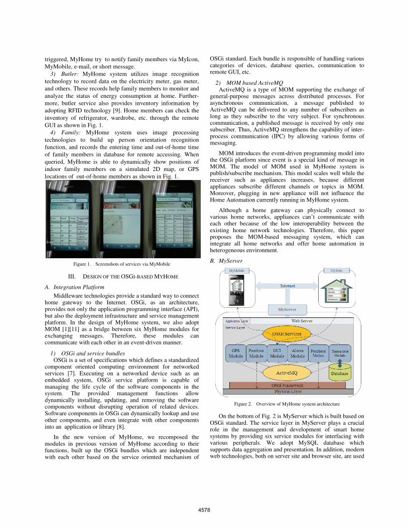
On the bottom of Fig. 2 is MyServer which is built based on OSGi standard. The service layer in MyServer plays a crucial role in the management and development of smart home systems by providing six service modules for interfacing with various peripherals. We adopt MySQL database which supports data aggregation and presentation. In addition, modern web technologies, both on server site and browser site, are used
4578
SMC 2009
to build dynamic web pages for the remote GUI MyIcon and MyMobile, as indicated on the top of Fig. 2.
In the physical layer, we adopt Zigbee and other communi-cation channel to collect information and to integrate services of security, inventory and health-care. Household devices for these services are connected with connectors which we call Zigbee End Devices (ZEDs). These end devices are then linked as a star topology network with centralized control at the Zigbee Coordinator (ZC), which is the central dispatcher managing the whole network. The coordinator is then connected to MyServer via a RS232 serial line [4]. Finally, the database on MyServer stores all kinds of data feedback from connected household devices.
1) Design of MyServer: This paper proposes the OSGi-based messaging system by
which each module is able to communicate with each other via both service oriented mechanism and message oriented mechanism as shown in Fig. 3, thus every module of OSGi-based MyHome can be triggered through event-driven mechanism and use the functions of each other via OSGi service registry. This design makes OSGi-based MyHome being able to combine the functions of these modules in more scalable way. Moreover, the design of OSGi-based MyHome is independent of any home networking technology and integrates home networking technologies in home gateway.
Figure 3. Functionalities of core modules
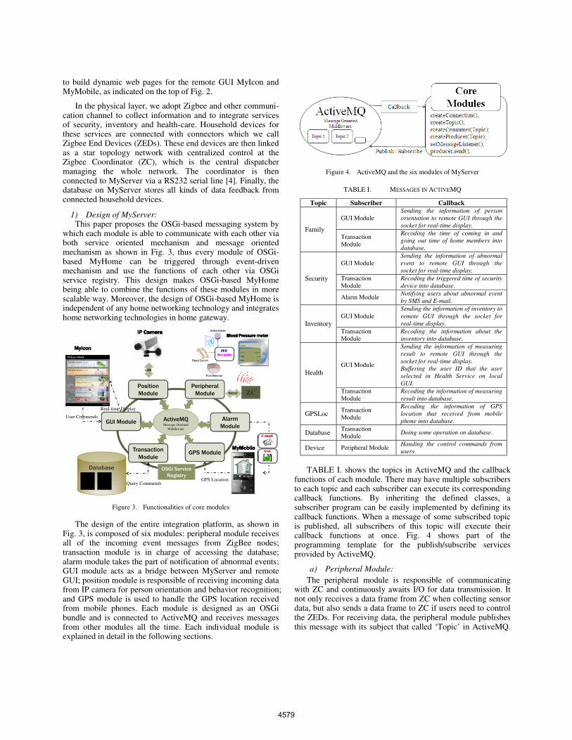
The design of the entire integration platform, as shown in Fig. 3, is composed of six modules: peripheral module receives all of the incoming event messages from ZigBee nodes; transaction module is in charge of accessing the database; alarm module takes the part of notification of abnormal events; GUI module acts as a bridge between MyServer and remote GUI; position module is responsible of receiving incoming data from IP camera for person orientation and behavior recognition; and GPS module is used to handle the GPS location received from mobile phones. Each module is designed as an OSGi bundle and is connected to ActiveMQ and receives messages from other modules all the time. Each individual module is explained in detail in the following sections.
Figure 4. ActiveMQ and the six modules of MyServer
TABLE I. MESSAGES IN ACTIVEMQ
Topic Subscriber Callback
Family
GUI Module Sending the information of person orientation to remote GUI through the socket for real-time display.
Transaction Module
Recoding the time of coming in and going out time of home members into database.
Security
GUI Module Sending the information of abnormal event to remote GUI through the socket for real-time display.
Transaction Module
Recoding the triggered time of security device into database.
Alarm Module Notifying users about abnormal event by SMS and E-mail.
InventoryGUI Module
Sending the information of inventory to remote GUI through the socket for real-time display.
Transaction Module
Recoding the information about the inventory into database.
Health GUI Module
Sending the information of measuring result to remote GUI through the socket for real-time display. Buffering the user ID that the user selected in Health Service on local GUI.
Transaction Module
Recoding the information of measuring result into database.
GPSLoc Transaction Module
Recoding the information of GPS location that received from mobile phone into database.
DatabaseTransaction Module
Doing some operation on database.
Device Peripheral Module Handing the control commands from users
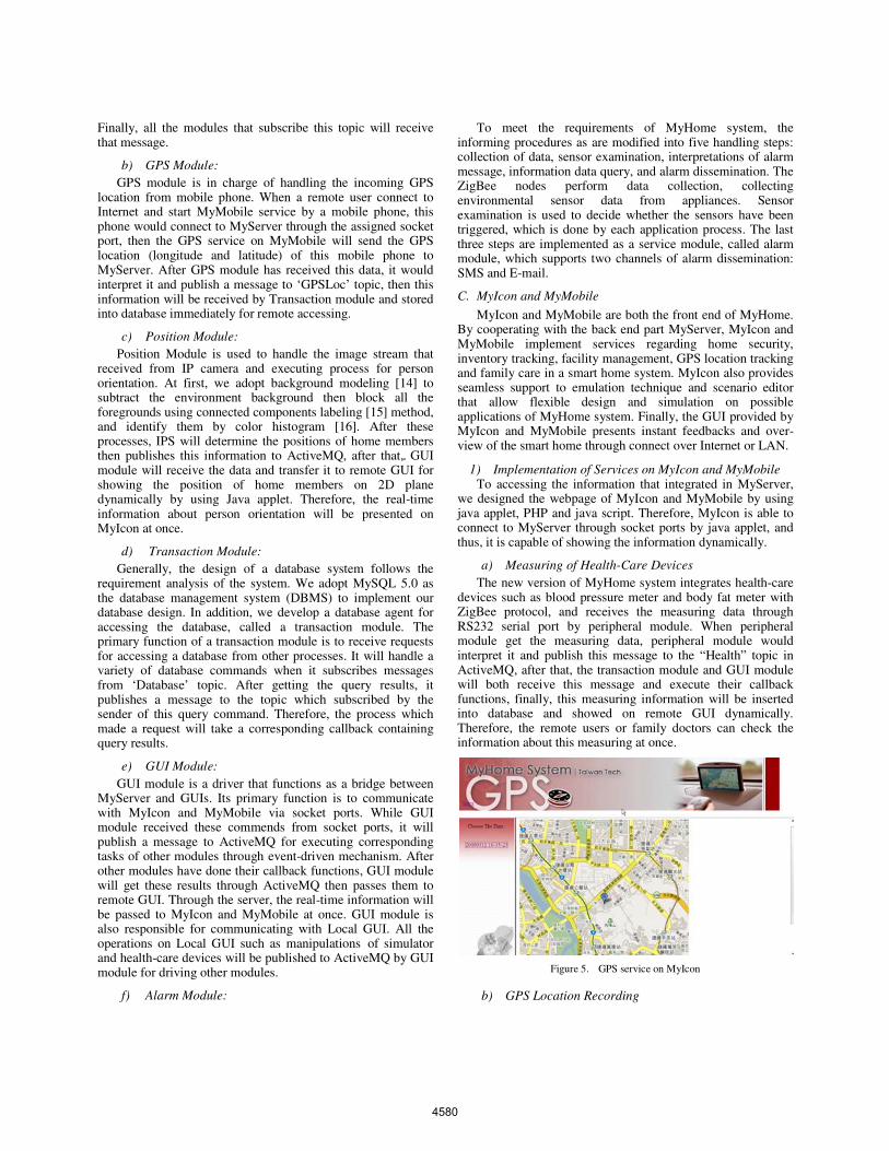
TABLE I. shows the topics in ActiveMQ and the callback functions of each module. There may have multiple subscribers to each topic and each subscriber can execute its corresponding callback functions. By inheriting the defined classes, a subscriber program can be easily implemented by defining its callback functions. When a message of some subscribed topic is published, all subscribers of this topic will execute their callback functions at once. Fig. 4 shows part of the programming template for the publish/subscribe services provided by ActiveMQ.
a) Peripheral Module: The peripheral module is responsible of communicating
with ZC and continuously awaits I/O for data transmission. It not only receives a data frame from ZC when collecting sensor data, but also sends a data frame to ZC if users need to control the ZEDs. For receiving data, the peripheral module publishes this message with its subject that called ‘Topic’ in ActiveMQ.
MyMobileMyMobileMyMobileMyMobile
Alarm Module
Table 1 Table 2
Database
…
RS232
LAN
IP CameraIP CameraIP CameraIP Camera
GPS Module
Peripheral Module
Transaction Module
GUI Module
ZC
Query CommendsGPS Location
User Commends
Real-time Display
Blood Pressure meterBlood Pressure meterBlood Pressure meterBlood Pressure meter
ActiveMQMessage Oriented
Middleware
OSGi Service Registry
Position Module
MyIconMyIconMyIconMyIcon
4579
SMC 2009
Finally, all the modules that subscribe this topic will receive that message.
b) GPS Module: GPS module is in charge of handling the incoming GPS
location from mobile phone. When a remote user connect to Internet and start MyMobile service by a mobile phone, this phone would connect to MyServer through the assigned socket port, then the GPS service on MyMobile will send the GPS location (longitude and latitude) of this mobile phone to MyServer. After GPS module has received this data, it would interpret it and publish a message to ‘GPSLoc’ topic, then this information will be received by Transaction module and stored into database immediately for remote accessing.
c) Position Module: Position Module is used to handle the image stream that
received from IP camera and executing process for person orientation. At first, we adopt background modeling [14] to subtract the environment background then block all the foregrounds using connected components labeling [15] method, and identify them by color histogram [16]. After these processes, IPS will determine the positions of home members then publishes this information to ActiveMQ, after that, GUI module will receive the data and transfer it to remote GUI for showing the position of home members on 2D plane dynamically by using Java applet. Therefore, the real-time information about person orientation will be presented on MyIcon at once.
d) Transaction Module: Generally, the design of a database system follows the
requirement analysis of the system. We adopt MySQL 5.0 as the database management system (DBMS) to implement our database design. In addition, we develop a database agent for accessing the database, called a transaction module. The primary function of a transaction module is to receive requests for accessing a database from other processes. It will handle a variety of database commands when it subscribes messages from ‘Database’ topic. After getting the query results, it publishes a message to the topic which subscribed by the sender of this query command. Therefore, the process which made a request will take a corresponding callback containing query results.
e) GUI Module: GUI module is a driver that functions as a bridge between
MyServer and GUIs. Its primary function is to communicate with MyIcon and MyMobile via socket ports. While GUI module received these commends from socket ports, it will publish a message to ActiveMQ for executing corresponding tasks of other modules through event-driven mechanism. After other modules have done their callback functions, GUI module will get these results through ActiveMQ then passes them to remote GUI. Through the server, the real-time information will be passed to MyIcon and MyMobile at once. GUI module is also responsible for communicating with Local GUI. All the operations on Local GUI such as manipulations of simulator and health-care devices will be published to ActiveMQ by GUI module for driving other modules.
f) Alarm Module:
To meet the requirements of MyHome system, the informing procedures as are modified into five handling steps: collection of data, sensor examination, interpretations of alarm message, information data query, and alarm dissemination. The ZigBee nodes perform data collection, collecting environmental sensor data from appliances. Sensor examination is used to decide whether the sensors have been triggered, which is done by each application process. The last three steps are implemented as a service module, called alarm module, which supports two channels of alarm dissemination: SMS and E-mail.
C. MyIcon and MyMobile
MyIcon and MyMobile are both the front end of MyHome. By cooperating with the back end part MyServer, MyIcon and MyMobile implement services regarding home security, inventory tracking, facility management, GPS location tracking and family care in a smart home system. MyIcon also provides seamless support to emulation technique and scenario editor that allow flexible design and simulation on possible applications of MyHome system. Finally, the GUI provided by MyIcon and MyMobile presents instant feedbacks and over-view of the smart home through connect over Internet or LAN.
1) Implementation of Services on MyIcon and MyMobile To accessing the information that integrated in MyServer,
we designed the webpage of MyIcon and MyMobile by using java applet, PHP and java script. Therefore, MyIcon is able to connect to MyServer through socket ports by java applet, and thus, it is capable of showing the information dynamically.
a) Measuring of Health-Care Devices The new version of MyHome system integrates health-care
devices such as blood pressure meter and body fat meter with ZigBee protocol, and receives the measuring data through RS232 serial port by peripheral module. When peripheral module get the measuring data, peripheral module would interpret it and publish this message to the “Health” topic in ActiveMQ, after that, the transaction module and GUI module will both receive this message and execute their callback functions, finally, this measuring information will be inserted into database and showed on remote GUI dynamically. Therefore, the remote users or family doctors can check the information about this measuring at once.
Figure 5. GPS service on MyIcon
b) GPS Location Recording
4580
SMC 2009
For the GPS service on MyIcon and MyMobile, we implemented the program in mobile phone for getting the ID of the SIM card in this mobile phone and its GPS location as mentioned in previous section, while a user start the GPS service by mobile phone, this mobile phone will connect to MyServer through the socket port and send a message which includes the ID of SIM card, longitude and latitude of its GPS location to MyServer. By using PHP, java script and Google Maps API, the remote GUIs, MyIcon and MyMobile can display the GPS location of home members on Google Map [13] without saving any graph in MyServer as show in Fig. 5.
2) Design of Local GUI For some operations on MyHome System and the detailed
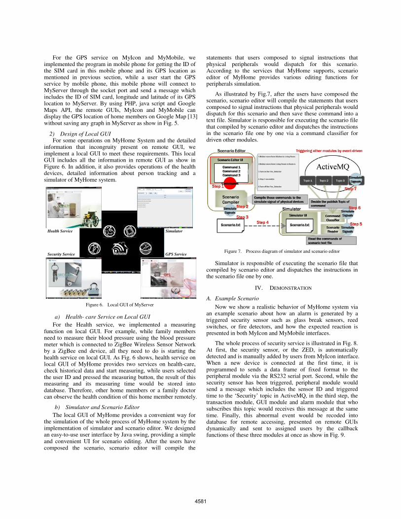
information that incongruity present on remote GUI, we implement a local GUI to meet these requirements. This local GUI includes all the information in remote GUI as show in Figure 6. In addition, it also provides operations of the health devices, detailed information about person tracking and a simulator of MyHome system.
Figure 6. Local GUI of MyServer
a) Health- care Service on Local GUI For the Health service, we implemented a measuring
function on local GUI. For example, while family members need to measure their blood pressure using the blood pressure meter which is connected to ZigBee Wireless Sensor Network by a ZigBee end device, all they need to do is starting the health service on local GUI. As Fig. 6 shows, health service on local GUI of MyHome provides two services on health-care, check historical data and start measuring, while users selected the user ID and pressed the measuring button, the result of this measuring and its measuring time would be stored into database. Therefore, other home members or a family doctor can observe the health condition of this home member remotely.
b) Simulator and Scenario Editor The local GUI of MyHome provides a convenient way for
the simulation of the whole process of MyHome system by the implementation of simulator and scenario editor. We designed an easy-to-use user interface by Java swing, providing a simple and convenient UI for scenario editing. After the users have composed the scenario, scenario editor will compile the
statements that users composed to signal instructions that physical peripherals would dispatch for this scenario. According to the services that MyHome supports, scenario editor of MyHome provides various editing functions for peripherals simulation.
As illustrated by Fig.7, after the users have composed the scenario, scenario editor will compile the statements that users composed to signal instructions that physical peripherals would dispatch for this scenario and then save these command into a text file. Simulator is responsible for executing the scenario file that compiled by scenario editor and dispatches the instructions in the scenario file one by one via a command classifier for driven other modules.
Figure 7. Process diagram of simulator and scenario editor
Simulator is responsible of executing the scenario file that compiled by scenario editor and dispatches the instructions in the scenario file one by one.
IV. DEMONSTRATION
A. Example Scenario
Now we show a realistic behavior of MyHome system via an example scenario about how an alarm is generated by a triggered security sensor such as glass break sensors, reed switches, or fire detectors, and how the expected reaction is presented in both MyIcon and MyMobile interfaces.
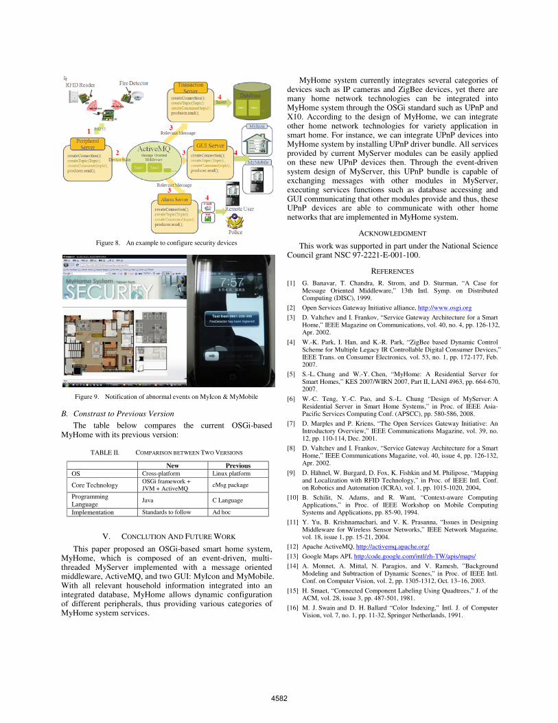
The whole process of security service is illustrated in Fig. 8. At first, the security sensor, or the ZED, is automatically detected and is manually added by users from MyIcon interface. When a new device is connected at the first time, it is programmed to sends a data frame of fixed format to the peripheral module via the RS232 serial port. Second, while the security sensor has been triggered, peripheral module would send a message which includes the sensor ID and triggered time to the ‘Security’ topic in ActiveMQ, in the third step, the transaction module, GUI module and alarm module that who subscribes this topic would receives this message at the same time. Finally, this abnormal event would be recoded into database for remote accessing, presented on remote GUIs dynamically and sent to assigned users by the callback functions of these three modules at once as show in Fig. 9.
31
Health Service
GPS ServiceSecurity Service
Simulator
4581
SMC 2009
Figure 8. An example to configure security devices
Figure 9. Notification of abnormal events on MyIcon & MyMobile
B. Constrast to Previous Version
The table below compares the current OSGi-based MyHome with its previous version:
TABLE II. COMPARISON BETWEEN TWO VERSIONS
New PreviousOS Cross-platform Linux platform
Core Technology OSGi framework + JVM + ActiveMQ
cMsg package
Programming Language
Java C Language
Implementation Standards to follow Ad hoc
V. CONCLUTION AND FUTURE WORK
This paper proposed an OSGi-based smart home system, MyHome, which is composed of an event-driven, multi-threaded MyServer implemented with a message oriented middleware, ActiveMQ, and two GUI: MyIcon and MyMobile. With all relevant household information integrated into an integrated database, MyHome allows dynamic configuration of different peripherals, thus providing various categories of MyHome system services.
MyHome system currently integrates several categories of devices such as IP cameras and ZigBee devices, yet there are many home network technologies can be integrated into MyHome system through the OSGi standard such as UPnP and X10. According to the design of MyHome, we can integrate other home network technologies for variety application in smart home. For instance, we can integrate UPnP devices into MyHome system by installing UPnP driver bundle. All services provided by current MyServer modules can be easily applied on these new UPnP devices then. Through the event-driven system design of MyServer, this UPnP bundle is capable of exchanging messages with other modules in MyServer, executing services functions such as database accessing and GUI communicating that other modules provide and thus, these UPnP devices are able to communicate with other home networks that are implemented in MyHome system.
ACKNOWLEDGMENT
This work was supported in part under the National Science Council grant NSC 97-2221-E-001-100.
REFERENCES
[1] G. Banavar, T. Chandra, R. Strom, and D. Sturman, “A Case for Message Oriented Middleware,” 13th Intl. Symp. on Distributed Computing (DISC), 1999.
[2] Open Services Gateway Initiative alliance, http://www.osgi.org
[3] D. Valtchev and I. Frankov, “Service Gateway Architecture for a Smart Home,” IEEE Magazine on Communications, vol. 40, no. 4, pp. 126-132, Apr. 2002.
[4] W.-K. Park, I. Han, and K.-R. Park, “ZigBee based Dynamic Control Scheme for Multiple Legacy IR Controllable Digital Consumer Devices,” IEEE Trans. on Consumer Electronics, vol. 53, no. 1, pp. 172-177, Feb. 2007.
[5] S.-L. Chung and W.-Y. Chen, “MyHome: A Residential Server for Smart Homes,” KES 2007/WIRN 2007, Part II, LANI 4963, pp. 664-670, 2007.
[6] W.-C. Teng, Y.-C. Pao, and S.-L. Chung “Design of MyServer: A Residential Server in Smart Home Systems,” in Proc. of IEEE Asia-Pacific Services Computing Conf. (APSCC), pp. 580-586, 2008.
[7] D. Marples and P. Kriens, “The Open Services Gateway Initiative: An Introductory Overview,” IEEE Communications Magazine, vol. 39, no. 12, pp. 110-114, Dec. 2001.
[8] D. Valtchev and I. Frankov, “Service Gateway Architecture for a Smart Home,” IEEE Communications Magazine, vol. 40, issue 4, pp. 126-132, Apr. 2002.
[9] D. Hähnel, W. Burgard, D. Fox, K. Fishkin and M. Philipose, “Mapping and Localization with RFID Technology,” in Proc. of IEEE Intl. Conf. on Robotics and Automation (ICRA), vol. 1, pp. 1015-1020, 2004.
[10] B. Schilit, N. Adams, and R. Want, “Context-aware Computing Applications,” in Proc. of IEEE Workshop on Mobile Computing Systems and Applications, pp. 85-90, 1994.
[11] Y. Yu, B. Krishnamachari, and V. K. Prasanna, “Issues in Designing Middleware for Wireless Sensor Networks,” IEEE Network Magazine,vol. 18, issue 1, pp. 15-21, 2004.
[12] Apache ActiveMQ, http://activemq.apache.org/
[13] Google Maps API, http:/code.google.com/intl/zh-TW/apis/maps/
[14] A. Monnet, A. Mittal, N. Paragios, and V. Ramesh, ”Background Modeling and Subtraction of Dynamic Scenes,” in Proc. of IEEE Intl. Conf. on Computer Vision, vol. 2, pp. 1305-1312, Oct. 13–16, 2003.
[15] H. Smaet, “Connected Component Labeling Using Quadtrees,” J. of the ACM, vol. 28, issue 3, pp. 487-501, 1981.
[16] M. J. Swain and D. H. Ballard, “Color Indexing,” Intl. J. of Computer Vision, vol. 7, no. 1, pp. 11-32, Springer Netherlands, 1991.
4582