Embed Size (px)
Citation preview

Installation, Operating
and Maintenance Manual
SMART FPS LX & LX-FSMART Fuel Polishing Systems

2 www.dieselfueldoctor.com Phone: 517.605.5788 • FAX: 888.221.2214 [email protected]

3
INSTALLATION, OPERATING AND MAINTENANCE MANUAL
TABLE OF CONTENTS
GENERAL SPECIFICATIONS ..................................................................................................................................................9
SYSTEM COMPONENTS.........................................................................................................................................................9
PRIMARY INSPECTION ........................................................................................................................................................ 10
INSTALLATION....................................................................................................................................................................... 10 Mounting............................................................................................................................................................................................................................................................. 10
Electrical ............................................................................................................................................................................................................................................................... 10
Plumbing ............................................................................................................................................................................................................................................................. 11
IMPORTANT INSTALLATION PRECAUTIONS ............................................................................................................... 12
PRIMING THE SYSTEM......................................................................................................................................................... 12
SMART FPS ALARM FEATURES......................................................................................................................................... 12
INITIAL START-UP / COMMISSIONING CHECKLIST.................................................................................................... 13 Initial test procedure .................................................................................................................................................................................................................................... 13
OPERATION ............................................................................................................................................................................ 13 Pump Operation ............................................................................................................................................................................................................................................. 13
Programming the Timer ............................................................................................................................................................................................................................ 13
Gauge venting / accuracy......................................................................................................................................................................................................................... 14
Fuel Line Leak ................................................................................................................................................................................................................................................... 14
Stabilizing and Optimizing Fuel Quality........................................................................................................................................................................................... 15
MAINTENANCE...................................................................................................................................................................... 15 Preventative Maintenance........................................................................................................................................................................................................................ 15
Servicing primary filter ................................................................................................................................................................................................................................ 16
Servicing water separator.......................................................................................................................................................................................................................... 17
TROUBLESHOOTING............................................................................................................................................................ 18
AUTOMATED FUEL FILTRATION SYSTEMS WARRANTY.......................................................................................... 20
TECHNICAL ASSISTANCE AND ORDERING .................................................................................................................. 21 Replacement filter elements ................................................................................................................................................................................................................... 21
SMART FPS SYSTEM IDENTIFICATION........................................................................................................................... 21
APPENDIX A - ABBREVIATIONS USED IN THIS MANUAL......................................................................................... 22
www.dieselfueldoctor.com Phone: 517.605.5788 • FAX: 888.221.2214 [email protected]

4 www.dieselfueldoctor.com Phone: 517.605.5788 • FAX: 888.221.2214 [email protected]

www.dieselfueldoctor.com Phone: 517.605.5788 • FAX: 888.221.2214 [email protected]

= 7 www.dieselfueldoctor.com Phone: 517.605.5788 • FAX: 888.221.2214 [email protected]

= 8
The Smart FPS LX & LX-F Fuel Polishing Systems include a plug and play SFC-55 Smart Filtration Controller with text display. Algae-X FPS systems and “Smart Filtration Controllers” are modular, fully automated and programmable fuel polishing systems. The wiring harness with plugs easily connects the Smart Controller box with the FPS allowing for greater flexibility in installation and access to the control box where it’s most convenient for you.
Smart FPS LX & LX-F Systems:
- remove water and sludge to keep your tanks clean and your stored fuel in "pristine condition" at all times
- decontaminate, clean and optimize the condition of the “fresh” fuel you take on board
- transfer fuel from one tank to another and fill your day tank
Smart FPS Accessories: AFC-705 Fuel Catalyst, Wide Range of Filter Elements, Rotor Sight Glass, Foot Valve, Digital Flow Meter
Algae-X SFC-55 Smart Filtration Controller
The SFC-55 is a fully automated filtration controller with digital text readout of alarm and system status. The system’s operating functions are easy to program for scheduled periodic fuel maintenance.
The three color-coded lights give an instant visual status report of system
power (green), pump running (orange), and alarm (red). The alarm reset is the easily accessible large (blue) push button. The selector switch provides the option of manual operation or running the fully automated program.
SFC-55 Smart Filtration Controller
Typical Installation for Smart FPS LX-F
www.dieselfueldoctor.com Phone: 517.605.5788 • FAX: 888.221.2214 [email protected]

GENERAL SPECIFICATIONS SMART FPS LX Smart Filtration Controller .........................SFC-55 (connected with plugs / wire harness to filtration unit) Operating Temperature .............................32 - 104° F; 0 - 40° C Electrical ..................................................................115 V / 60 Hz / single phase (standard) .........................................................................................230 V / 50 Hz also available Pump .........................................................................Gear Pump Suction capability (primed) .......................15 ft vertical or 100 ft. horizontal lift (lines >1”, primed) Motor .........................................................................Single phase, continuous duty, thermally protected Max. Fluid Viscosity ...........................................5 cSt Further Specs........................................................see tables on page 4 & 6 (system specific) Note: The Smart FPS LX is designed to meet environmental standards for safe operation.
(NOT for use with fluids that have a flash point below 100°F (38°C), e.g.: gasoline, alcohol, …)
SYSTEM COMPONENTS CONTROL AND SAFETY DEVICES
• Algae-X “Smart Filtration Controller” SFC-55 in electrical sub enclosure, modular “Plug & Play” system
• Programmable Digital Timer – Memory backup to retain program memory during power outages • Pump control switch (Auto-Off-Manual), selector switch • Alarm Reset - push button • System power indicator • Pump running indicator • Alarm indicator • External remote shut-down feature • Dry contacts for remote monitoring • Leak sensor and alarm indicator (system shutdown) • Primary filter / water separator high vacuum alarm indicator and system shutdown (vacuum sensor) • Primary filter / water separator high water alarm indicator and system shutdown (water sensor) • Single-pole control circuit breaker • Single-pole power circuit breaker and motor contactor with overload relay
PUMP / MOTOR: • Positive displacement gear pump with Relief valve • Continuous Duty Motor – UL listed - Thermal overload protection
PRIMARY FILTER / WATER SEPARATOR • Fuel filter with water separator • Drain valve on the bottom • Analog vacuum gauge (stainless steel, liquid filled) • 30-micron filter cartridge (10-micron filter element available)
FUEL CONDITIONER • Inline Fuel Conditioner breaks down fuel sediments and fuel solids to submicron levels • Powder-coated, corrosion-resistant, aluminum back plate and spill containment tray • Stainless steel plumbing www.dieselfueldoctor.com Phone: 517.605.5788 • FAX: 888.221.2214 [email protected]

10
PRIMARY INSPECTION Upon arrival, the Smart FPS LX Fuel Polishing System and accessories must be visually inspected before installation. Improper handling during shipping may cause physical or electrical problems. Immediately report or note any damages (also concealed damages) to the shipper.
CHECKLIST: If the packing crate shows signs of damage inspect the Smart FPS for damage. Check the
cover, back plate and electrical enclosure (SFC 55) for damage that could indicate internal mechanical or electrical problems.
Check gauges for spilled liquid. Check all plumbing connections for tightness. Check all electrical terminals and connections for tightness.
INSTALLATION ! IMPORTANT ! It is recommended that only qualified, experienced personnel, familiar with this type of equipment, who have read and understood all the instructions in this manual should install, operate and maintain the system.
MOUNTING The Smart FPS LX and SFC-55 Smart Filtration Controller should be permanently wall mounted on a hard, level surface. Use provided mounting holes for proper fastening. This unit is designed for well-ventilated indoor use within specified temperature range and should be located as close to the tank as possible. Please allow sufficient space on top of the unit to change the filter element comfortably.
ELECTRICAL
! WARNING ! To avoid the risk of electric shock make sure that the power supply to the system is disconnected and ensure that the system is at zero volts, before working on any of the system’s electrical parts.
Make sure that the systems power requirements and rated voltage / frequency match your electrical system (See wiring diagram and / or marking on SFC-55). The Smart FPS LX may only be connected to properly grounded power sources for operator safety. Do not run over, crush or pull the power supply cable and wiring harness otherwise it may be damaged. Protect the cables from oil, heat and sharp edges.
! WARNING ! The system must be properly grounded for operator safety.
Depending on length of run, use #12 AWG or larger copper wiring and connect system to a separate UL listed breaker (not included) appropriate for branch circuit protection. Connect the SFC-55 Smart Filtration Controller to the filtration unit with the two provided plugs and wiring harnesses. Note: Wiring and electrical installation must be in accordance with all applicable Federal,
State and Local rules, laws, standards and regulations.
www.dieselfueldoctor.com Phone: 517.605.5788 • FAX: 888.221.2214 [email protected]

11
Remote Pump Shut-Down Feature: If required, connect the “external pump shut down input terminal” (see SFC-55 wiring diagram) per specification on electric diagram to disable pump (e.g.: remote shut down, remote pump control, …). Please note that the contact needs to be supplied with +24V DC from the power supply of the SFC-55 Smart Filtration Controller. Remote Monitoring - Dry Contacts: The SFC-55 provides two N.O. (normally open) dry contacts for remote alarm monitoring. Please see wiring diagram for contact rating, connection and location.
1. “Summary Alarm” – dry alarm contact for high vacuum, high pressure or water detection 2. “Leak Detection” – dry alarm contact for leak detection
PLUMBING Use proper quality approved fuel line materials with at least 1” inner diameter on the suction side from the tank and 1” inner diameter on the return / discharge side back to the tank. Do not put any stress on the plumbing connection and use a backing wrench when connecting plumbing to the Smart FPS LX. A full flow, shut-off ball valve should be installed on the inlet and outlet port / line of the Smart FPS system The pick-up tube/line(s) should originate from the lowest point of the tank (to remove all water), The pick-up tube/line(s) should be connected directly to the Smart FPS LX inlet port (Algae-X® Fuel Conditioner) located on the left hand side and kept as short as possible. For optimal performance, insure that the inlet (suction) line(s) are free and nothing is restricting their flow. It is recommended to install an oversized, low restriction foot valve to keep the system primed, especially if the inlet port of the system is located above the lowest possible fuel level in the tank. If the Smart FPS LX is mounted below tank top level, a priming tee should be installed on the highest point of the suction line to be able to easily prime the systems delivery line. The return line(s) should be plumbed to the outlet port (on the right side of the system) and enter the tank as far as possible from the pick up tube close to the tank bottom. For optimal performance, insure that the outlet (discharge or return) line(s) are free and nothing is restricting their flow. Multiple suction and/or return lines may be connected to a manifold. Anti-Siphon or other external plumbing devices may be required – please check local regulations / code. The system capabilities are 15 ft suction (vertical) or 100 ft horizontal lift, when connected to piping of 1” ID or more with no additional flow restrictions such as valves, 90-degree connectors or other plumbing accessories. For continuous optimal performance, make sure suction and discharge lines are free and that nothing is blocking the flow of fuel and that the suction line always stays primed. Note: Plumbing and Installation must be in accordance with all applicable Federal, State and
Local rules, laws, standards and regulations.
www.dieselfueldoctor.com Phone: 517.605.5788 • FAX: 888.221.2214 [email protected]

12
IMPORTANT INSTALLATION PRECAUTIONS The suction line of the system should be independent and separate from the suction line of the engine. If that is not possible, appropriate valves must be installed to completely separate the Smart FPS from the engine fuel system to prevent any possible interference with safe engine operation. If the return line from the engine and the discharge of the Smart FPS have to be combined in any way, adequate valves should be installed to prevent any possible interference with safe engine operation.
Note: If any of the Smart FPS LX system’s fuel lines are used in combination with the engine’s fuel system, the Smart FPS LX should be disabled during engine operation (use the provided “remote pump shut down” feature as shown in the electrical drawing and described above).
PRIMING THE SYSTEM The pump supplied with the Smart FPS LX is NOT automatically self-priming and must not be run dry.
! WARNING ! If the pump is allowed to run without fuel, pump damage will occur.
PRIMING PROCEDURE: The pump head of the Smart FPS LX unit is shipped from the factory filled with Diesel #2 to facilitate initial lubrication. This will not eliminate the necessity to prime the complete system. The Smart FPS LX is primed by using the externally installed priming tee (not provided) or by removing the lid of the primary filter and filling the complete filter housing and suction plumbing. The primary filter as well as the suction line(s) must be completely filled with fuel (no trapped air) prior to the initial system start-up.
SMART FPS ALARM FEATURES The system is equipped with a vacuum gauge on the input side of the pump. The gauge should read 0 to 15" HG vacuum maximum under normal conditions. Vacuum gauge readings reaching 16" HG vacuum indicate excessive debris in the primary filter/ water separator (or a flow restriction or too high suction height and therefore a pressure drop in the suction line) and will result in pump shutdown and activate the high vacuum alarm. Note: 16" HG vacuum = clogged primary filter or suction line flow restriction / excessive lift.
The system’s pressure gauge should show 22 PSI maximum pressure under normal conditions (.433 PSI = 1' vertical head pressure). Pressure gauge readings in excess of 22 PSI pressure indicate the need for filter replacement, or fuel line restrictions and/or friction. System pressure over 22 PSI indicates a high-pressure alarm and will automatically shut down the pump. The pump pressure relief valve has a 35-40 PSI set point. System pressure in excess of 35-40 PSI will cause the pressure relief valve to open and vent fuel back to the fuel transfer pump inlet side.
www.dieselfueldoctor.com Phone: 517.605.5788 • FAX: 888.221.2214 [email protected]

13
INITIAL START-UP / COMMISSIONING CHECKLIST INITIAL TEST PROCEDURE - Verify plumbing, wiring and system prime.
With breakers and power turned on and pump running check all alarms for proper operation: 1. Manually raise float switch located in drip/spill tray. Pump should immediately turn off and
“FUEL LEAK” should be displayed as well as the red indicator light will turn on. Reset alarm by pushing the “RESET ALARM” button on the control panel.
2. Slowly partially close inlet ball valve. At 16”HG pump should turn off and “PLS. SERVICE PRIM. FILTER” should be displayed as well as the red indicator light will illuminate. Open inlet ball valve again. Reset alarm by pushing the “RESET ALARM” button.
3. Slowly partially close outlet ball valve. At 22 PSI pump should turn off (after a delay of about 0.25 second) and “HIGH PRESS. ALARM” should be displayed as well as the red indicator light will illuminate. Open outlet ball valve again. Reset alarm by pushing the “RESET ALARM” button.
4. Short the two water contacts on the bowl of the primary filter with jumper. Pump should turn off and “PLS. DRAIN WATER/BOWL” should be displayed as well as the red indicator light will illuminate. Reset alarm by pushing the “RESET ALARM” button on the control panel.
Note: If any of the above described alarm test procedures fail or if any alarm trip value
deviates immediately contact Algae-X International.
OPERATION
! WARNING ! This System is not meant for use with gasoline nor with other flammable liquids having a flash point less than 100°F. Use with gasoline or use with any flammable liquids at a temperature exceeding their flash point, presents an immediate explosion and fire hazard. Never use the Smart FPS LX at a temperature exceeding the
flash point of its contents.
PUMP OPERATION Apply power to unit. Place breakers in the Algae-X SFC-55 Smart Filtration Controller in the “ON” position. Automatic: Place the selector switch in the “AUTO” position. When the programmable timer comes on, the pump will start and run until the timer setting has expired. Manual: Place the selector switch in the “MANUAL” position. The pump motor will run until the switch is returned to the “OFF” or “AUTO” mode positions or till an alarm or overload has been tripped.
PROGRAMMING THE TIMER The programmable timer is part of the Micro PLC settings of the Algae-X SFC-55 Smart Filtration Controller.
Note: The PLC uses military time – all times programmed must be in that format.
www.dieselfueldoctor.com Phone: 517.605.5788 • FAX: 888.221.2214 [email protected]
14
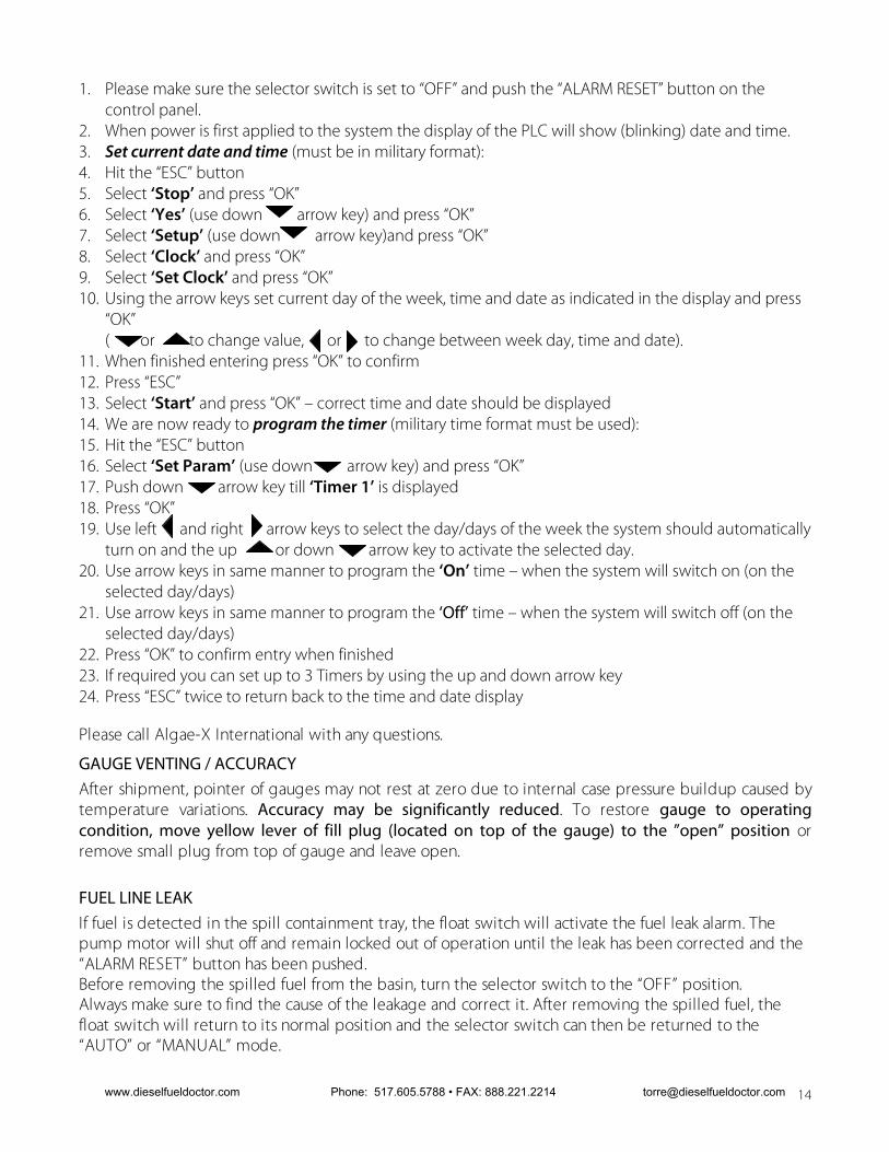
1. Please make sure the selector switch is set to “OFF” and push the “ALARM RESET” button on the control panel.
2. When power is first applied to the system the display of the PLC will show (blinking) date and time. 3. Set current date and time (must be in military format): 4. Hit the “ESC” button 5. Select ‘Stop’ and press “OK” 6. Select ‘Yes’ (use down arrow key) and press “OK” 7. Select ‘Setup’ (use down arrow key)and press “OK” 8. Select ‘Clock’ and press “OK” 9. Select ‘Set Clock’ and press “OK” 10. Using the arrow keys set current day of the week, time and date as indicated in the display and press
“OK” ( or to change value, or to change between week day, time and date).
11. When finished entering press “OK” to confirm 12. Press “ESC” 13. Select ‘Start’ and press “OK” – correct time and date should be displayed 14. We are now ready to program the timer (military time format must be used): 15. Hit the “ESC” button 16. Select ‘Set Param’ (use down arrow key) and press “OK” 17. Push down arrow key till ‘Timer 1’ is displayed 18. Press “OK” 19. Use left and right arrow keys to select the day/days of the week the system should automatically
turn on and the up or down arrow key to activate the selected day. 20. Use arrow keys in same manner to program the ‘On’ time – when the system will switch on (on the
selected day/days) 21. Use arrow keys in same manner to program the ‘Off’ time – when the system will switch off (on the
selected day/days) 22. Press “OK” to confirm entry when finished 23. If required you can set up to 3 Timers by using the up and down arrow key 24. Press “ESC” twice to return back to the time and date display Please call Algae-X International with any questions.
GAUGE VENTING / ACCURACY After shipment, pointer of gauges may not rest at zero due to internal case pressure buildup caused by temperature variations. Accuracy may be significantly reduced. To restore gauge to operating condition, move yellow lever of fill plug (located on top of the gauge) to the ”open” position or remove small plug from top of gauge and leave open.
FUEL LINE LEAK If fuel is detected in the spill containment tray, the float switch will activate the fuel leak alarm. The pump motor will shut off and remain locked out of operation until the leak has been corrected and the “ALARM RESET” button has been pushed. Before removing the spilled fuel from the basin, turn the selector switch to the “OFF” position. Always make sure to find the cause of the leakage and correct it. After removing the spilled fuel, the float switch will return to its normal position and the selector switch can then be returned to the “AUTO” or “MANUAL” mode.
www.dieselfueldoctor.com Phone: 517.605.5788 • FAX: 888.221.2214 [email protected]

15
Note: Disposal of fuel and associated waste should be done in accordance with Federal, State and Local regulations.
STABILIZING AND OPTIMIZING FUEL QUALITY We recommend treating the fuel with the ALGAE-X® Fuel Catalyst (AFC-705). The addition of AFC-705 will enhance and accelerate the tank cleaning process by breaking down and dissolving existing tank sludge. AFC-705 will decontaminate compartments of the tank that are out of reach of the suction line. Depending on the condition of the fuel and the amount of sludge build-up, it is recommended to initially use a double dose of one to twenty-five hundred (1:2500) instead of one to five thousand (1:5000) This has proven to be essential in accelerating the tank cleaning process. AFC-705 contains detergent, surfactant, dispersant, corrosion inhibitor, lubricity enhancer and combustion catalyst. It does not contain biocides. AFC-705 should always be used periodically in particular to stabilize fuel that is stored for longer periods of time. Note: In cases of severe tank contaminant build-up (sludge) and high water level in bottom, it
is recommended to clean the tank (vacuum bottom) and polish the fuel before initial use of a Smart FPS LX system.
MAINTENANCE ! IMPORTANT ! It is recommended that only qualified, experienced personnel, familiar with this equipment, who have read and understood all the instructions in this manual should install, operate and maintain the system.
! IMPORTANT ! Always disconnect the system from the electric power supply before working or servicing it. Do not proceed with any maintenance unless the pressure or vacuum has been released, the system has been allowed to reach ambient temperature
and all fluids have been drained.
PREVENTATIVE MAINTENANCE The Smart FPS LX Automated Fuel Filtration System should be visually inspected and tested a minimum of every six months according to the procedure below during light duty cycles. Monthly inspections are recommended for systems that are being used in excess of an average of 8 hours day and five days a week.
Prior to performing the maintenance procedure ensure that: 1. The electrical sub-panel mounted main disconnect switch is operating properly, 2. the user supplied remote circuit breaker is in the “Off” position, and 3. that all sources of power are isolated from the unit. 4. Proceed only after this has been verified and properly tagged.
Drain visible water and sediment from primary filter / water separator (see Servicing Primary Filter / Water Separator below).
Check all parts for corrosion and rust. Check mounting hardware. Tighten as necessary. Check pump/motor hardware for tightness. Pump/motor hardware will loosen after normal
operation due to vibration. This hardware is lock nutted, check all bolts for secure nuts. Check all electrical terminals and connections for tightness. All motors are permanently lubricated and do not require any lubrication. All pumps are self-lubricating and do not require any maintenance.
www.dieselfueldoctor.com Phone: 517.605.5788 • FAX: 888.221.2214 [email protected]

16
Check all plumbing joints for leaks. Tighten fittings and joints as necessary. Remove accumulated fuel in drip tray as necessary.
Inspect all filters and separators. See section below on filter inspection and service. With breakers and power turned on again and the pump running check all alarms for proper
operation: 1. Manually raise float switch located in drip/spill tray. Pump should immediately turn off and
“FUEL LEAK” should be displayed as well as the red indicator light will turn on. Reset alarm by pushing the “RESET ALARM” button on the control panel.
2. Slowly partially close inlet ball valve. At 16”HG pump should turn off and “PLS. SERVICE PRIM. FILTER” should be displayed as well as the red indicator light will illuminate. Open inlet ball valve again. Reset alarm by pushing the “RESET ALARM” button.
3. Slowly partially close outlet ball valve. At 22 PSI pump should turn off (after a delay of about 0.25 second) and “HIGH PRESS. ALARM” should be displayed as well as the red indicator light will illuminate. Open outlet ball valve again. Reset alarm by pushing the “RESET ALARM” button.
4. Short the two water contacts with jumper on the bowl of the primary filter. Pump should turn off and “PLS. DRAIN WATER/BOWL” should be displayed as well as the red indicator light will illuminate. Reset alarm by pushing the “RESET ALARM” button on the control panel.
Note: If any of the above described alarm test procedures fail or if any alarm trip value
deviates immediately contact Algae-X International. Note: All filter elements should be replaced at least every six months.
SERVICING PRIMARY FILTER Separ models: Set the telltale gauge pressure indicator (red pointer) to slightly above the black needle prior to operation. The gauge will indicate maximum vacuum pressure during system operation. Always keep the vent lever or plug on the gauge in the open position for accurate gauge reading.
A Clogged primary filter element will restrict the flow of fuel and the system’s vacuum gauge will indicate a pressure drop. The gauge is mounted on top of the primary filter. At a pressure drop of 16” HG, the pump will automatically shut off and activate the red indicator light and display “PLS. SERVICE PRIM. FILTER”. The signal indicates that it is time to either back-flush or replace the filter element.
Servicing and back-flushing Primary filter: 1. Turn selector switch to the “OFF” position – make sure pump will not turn on 2. Close the inlet and outlet ball valve (not provided) 3. Open the silver colored bleed screw at the top of the filter cover 4. Place a fuel waste container below the drain valve on the bottom of the filter bowl 5. Open the drain valve: push & turn counter clockwise) 6. Close after visible sediment, particles and water have been drained from the bowl 7. Prime the filter by removing the cover and pouring clean diesel fuel into the filter body until
the fuel level reaches the top of the filter body 8. Replace the lid. Note: Evenly tighten the wing bolts to ensure a good seal 9. Close bleed screw on top of the lid 10. Open the inlet and outlet ball valve 11. Push the “ALARM RESET” button on the control panel to acknowledge the alarm and reset it 12. Return the pump selector switch to “AUTO” or “MANUAL”
www.dieselfueldoctor.com Phone: 517.605.5788 • FAX: 888.221.2214 [email protected]

17
13. Check for leaks when re-starting and pressurizing the system. Your system is now ready to resume normal operation
Note: Primary filter elements can be back-flushed up to 5 times before element replacement is
required
SERVICING WATER SEPARATOR If the water level in the primary filter/water separator reaches a certain level in the bowl, the water sensor will trigger the high water alarm and shut off the pump. The signal indicates that it is time to drain the bowl on the water separator. Please follow procedures above – Service primary filter, steps 1-6.
SERVICING SECONDARY FILTER (LX-F ONLY) A Clogged secondary filter element restricts the flow of fuel and the system’s pressure gauge will indicate a pressure drop. The gauge is mounted on top of the secondary filter. At a pressure drop of 22 PSI (red dial area of the gauge) the pump will automatically shut off and activate the “HIGH PRESS. ALARM” indicator light. The signal indicates that it is time to change the filter element. There are several types of Algae-X spin on fine filters available; we recommend using the WB-3 (3 micron water block fine filter). The Algae-X Water Block incorporates polymer technology to remove emulsified water from fuel. Changing the secondary filter:
1. Turn selector switch to the “OFF” position – make sure pump will not turn on 2. Close the inlet and outlet ball valve (not provided) 3. Place an appropriate container underneath the filter 4. Remove old spin on filter by turning the cartridge counter clock wise seen from the bottom of
the cartridge 5. Apply a film of lubricating oil to the gasket of the new filter. Screw the new filter canister to
the filter head until the gasket is tight and secure (an additional ½ to one turn after the filter makes contact with the gasket)
6. Open the inlet and outlet ball valve 7. If needed, push the “ALARM RESET” button on the control panel to acknowledge the alarm and reset it 8. Return the pump selector selector switch to “AUTO” or “MANUAL” 9. Check for leaks when re-starting and pressurizing the system
Your system is now ready to resume normal operation
Note: Disposal of fuel, associated waste and filters should be done in accordance with Federal, State and Local regulations.
! WARNING ! Some fuels may have been treated with biocides. Biocides are extremely toxic and may enter the body through the skin. It is recommended to use adequate protection and proper precautions if fuel contains biocide type products.
www.dieselfueldoctor.com Phone: 517.605.5788 • FAX: 888.221.2214 [email protected]

TROUBLESHOOTING No fuel delivery 1. Pump does not run 2. Pump is not primed 3. Fuel supply line blocked / no fuel in tank 4. Excessive lift 5. Air leak in fuel supply to pump 6. Pump rotation direction incorrect 7. Intake or outlet valve closed 8. Check valve installed backwards (if installed)
Insufficient fuel delivered 1. Air leak at inlet 2. Defective pressure relief valve or check valve 3. Excessive lift 4. Pump worn 5. Inoperative foot valve 6. Piping improperly installed or dimensioned 7. Primary filter/water separator plugged
Rapid pump wear 1. Worn pump/motor coupler 2. Pump has been run dry or with insufficient fuel 3. Plumbing on inlet side not appropriately dimensioned
Alarm “PLS. SERVICE PRIM. FILTER” comes on with clean or new filter element installed 1. Heavily contaminated fuel / excessive water in tank 2. Restriction in plumbing on inlet side too high 3. Excessive lift 4. Inoperative foot valve 5. Inlet ball valve not fully open 6. Suction line clogged
Alarm “HIGH PRESS. ALARM” comes on with clean or new filter element installed 1. Heavily contaminated fuel / excessive water in tank 2. Restriction in plumbing on discharge side too high 3. Head (lift) on discharge side too high 4. Check valve stuck or defective 5. Outlet ball valve not fully open 6. Discharge line clogged
Pump requires too much power 1. Air in plumbing lines 2. Liquid too viscous 3. Bent pump shaft, binding rotor
www.dieselfueldoctor.com Phone: 517.605.5788 • FAX: 888.221.2214 [email protected]

19
Noisy operation 1. Insufficient fuel supply 2. Air leaks in the inlet pipe 3. Air or gas in fuel on the suction side
Pump requires frequent re-priming 1. Inoperative foot valve (if installed) 2. Inoperative check valve (if installed) 3. Pump cavitations 4. Plumbing air leaks 5. Lift too high 6. Leaking pump seal
Motor does not turn or turns intermittently 1. No Power / power failure / low voltage or bad power connection 2. Motor thermal overload condition (see below) 3. Pump failed and seized 4. Motor failure
Pump leaks fuel 1. Loose pump plumbing fittings 2. Worn pump shaft seal 3. Pump pressure relief valve failure 4. Fuel leak elsewhere and fuel dripping or running towards the pump 5. Excessive head from overhead storage tank 6. Worn pump O-rings or seals Motor overload relay (OLR) tripped Remove front panel of Smart Filtration Controller and push reset button on OLR relay, close panel again and push “ALARM RESET” button on door panel to return to resume operation.
www.dieselfueldoctor.com Phone: 517.605.5788 • FAX: 888.221.2214 [email protected]

20
AUTOMATED FUEL FILTRATION SYSTEMS WARRANTY
LIMITED PARTS WARRANTY
ALGAE-X® International makes every effort to assure that its products meet high quality and durability standards and expressly warrants the products described herein, against defects in material and workmanship for a period of one (1) year from the date of purchase. This warranty is not intended to supplant normal inspection, care and service of the products covered by the user, and shall not obligate ALGAE-X® to provide free service during the warranty period to correct breakage, maladjustment or other difficulties arising out of abuse, misuse, or improper care and maintenance of such products. Our express warranty is subject to the following terms and conditions: This warranty shall only extend to and is only for the benefit of original purchasers who use the products covered hereby Any warranty claim received by ALGAE-X® after one (1) year from the date of purchase will not be honored even if it is claimed that the defect occurred prior to one (1) year from the date of purchase. This warranty shall not apply to products (1) which have been tampered with, altered or repaired by anyone other than ALGAE-X® without the express prior written consent of ALGAE-X® (2) which have been installed improperly or subject to misuse, abuse, accident, negligence of others, improper operation or maintenance, neglect or modification, or (3) which have had the serial number altered, defaced or removed. The liability of ALGAE-X® under this warranty is limited to the repair or replacement of the defective product or components. ALGAE-X® assumes NO LIABILITY for labor charges or other costs incurred by any purchaser incidental to the service, adjustment, repair, return, removal or replacement of products. ALGAE-X® ASSUMES NO LIABILITY FOR ANY GENERAL, SPECIAL, INCIDENTAL, CONSEQUENTIAL, CONTINGENT OR OTHER DAMAGES UNDER ANY WARRANTY, EXPRESS OR IMPLIED, AND ALL SUCH LIABILITY IS HEREBY EXPRESSLY EXCLUDED. ALGAE-X® MAKES NO WARRANTIES, EXPRESS OR IMPLIED, OF MERCHANTABILITY, FITNESS FOR A PARTICULAR PURPOSE OR OTHERWISE, WITH RESPECT TO THE PRODUCTS COVERED BY THIS WARRANTY POLICY, EXCEPT AS EXPRESSLY PROVIDED FOR HEREIN. NO EMPLOYEE, AGENT, REPRESENTATIVE OR DISTRIBUTOR IS AUTHORIZED TO MAKE ANY WARRANTY ON BEHALF OF ALGAE-X® OTHER THAN THE EXPRESS WARRANTY PROVIDED FOR HEREIN. ALGAE-X® reserves the right at any time to make changes in the design, material, function and specifications of its products. Any such changes shall not obligate ALGAE-X® to make similar changes in such products that were previously manufactured.
WARRANTY CLAIM PROCEDURE To make a claim under this warranty, please call our ALGAE-X® at (239) 690 9589 or (877) 425-4239, and provide: Name and location where unit was purchased, the date and receipt of purchase, model number, serial number, and a detailed explanation of the problem you are experiencing. The Customer Service Representative may, at the discretion of ALGAE-X®, arrange for a Field Engineer to inspect your system. If the inspection discloses a defect covered by its limited warranty, ALGAE-X® will either repair or replace the defective parts or products. ALGAE-X® assumes no liability, if upon inspection, ALGAE-X® or its representative determines that there is no defect or that the damage to the system resulted from causes not within the scope of this limited warranty. For service and sales, please contact ALGAE-X®:
www.dieselfueldoctor.com Phone: 517.605.5788 • FAX: 888.221.2214 [email protected]

TECHNICAL ASSISTANCE AND ORDERING Please write, fax, email or call: ALGAE-X® International 5400-1 Division Drive Fort Myers, FL 33905
Tel: 239-690-9589 Fax: 239-690-1195 Email: [email protected] Internet: www.algae-x.net
Please provide the following information: Serial Number of your Smart FPS, the required part numbers and quantity.
REPLACEMENT FILTER ELEMENTS Primary Filter: 04060S 60 Micron Stainless Steel re-usable, cleanable filter element 04030 30 Micron replacement filter element 04010 10 Micron replacement filter element 30440 Lid Gasket Also available:
• Larger or smaller capacity, custom designed systems for higher or lower flow rates • Digital Flow Meter • Foot Valves • Rotor Sight Glass
SMART FPS SYSTEM IDENTIFICATION Serial Number:_________________________________________ (e.g. B 070010 – FLX) System Specification: Voltage:
120 V AC / 60 Hz 230 V AC / 50 Hz
Inspected by: ______________________________ Date: ________________
www.dieselfueldoctor.com Phone: 517.605.5788 • FAX: 888.221.2214 [email protected]

22
APPENDIX A - ABBREVIATIONS USED IN THIS MANUAL Abbreviations of terms used with Automated Fuel Filtration Systems. When following a drawing utilize this guide to define abbreviated system and component names. This is a master list. The drawings and text pertaining to your equipment may not contain all these terms. AC Alternating Current
BRK Motor/Pump Bracket
BV Ball Valve
C Contactor
CB Circuit Breaker
CV Check Valve
DC Direct Current
DPDT Double Pole Double Throw
F Fuse
FS Float switch
GA Gauge
GAL Gallons
GPM Gallons Per Minute
HG Mercury
HP Horsepower
HZ Hertz
I.D. Inside Diameter
JB Junction Box
“ HG Inches of Mercury
L Lamp
L.E.D. Light Emitting Diode
MDB Main Distribution Block
MDS Main Disconnect Switch
MOT Motor
N.C. Normally Closed
NEC National Electric Code
NEMA National Electric Manufacturers Assoc.
N.O. Normally Open
NPT National Pipe Thread
O.D. Outside Diameter
OLR Over Load Relay
OPT Option
PG Pressure Gauge
PRV Pressure Relief Valve
PRS Pressure Switch
PS Power Supply
PSI Pounds Per Square Inch
PSR Pressure Switch Relay
PRR Pump Running Relay
TB Terminal Block
T Control Transformer
TEFC Totally Enclosed, Fan Cooled
V Voltage
VAC Voltage, Alternating Current
VDC Voltage, Direct Current
VG Vacuum Gauge
www.dieselfueldoctor.com Phone: 517.605.5788 • FAX: 888.221.2214 [email protected]

www.dieselfueldoctor.com Phone: 517.605.5788 • FAX: 888.221.2214 [email protected]