Embed Size (px)
Citation preview

LIT-12011998-UTB-A-0714
Smart Equipment Control (SEC)Technical Bulletin
Smart Equipment Control Board (SEC) 2-Stage
Smart Equipment Control Board (SEC) Single Stage with Optional Communication Board
Smart Equipment Control (SEC) Technical Bulletin 1
LIT-12011998-UTB-A-0714
Smart Equipment Control (SEC) Technical Bulletin
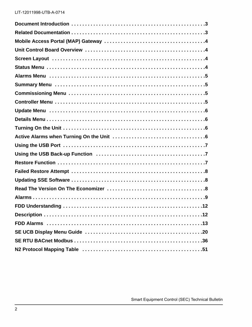
Document Introduction . . . . . . . . . . . . . . . . . . . . . . . . . . . . . . . . . . . . . . . . . . . . . . . . .3
Related Documentation . . . . . . . . . . . . . . . . . . . . . . . . . . . . . . . . . . . . . . . . . . . . . . . . .3
Mobile Access Portal (MAP) Gateway . . . . . . . . . . . . . . . . . . . . . . . . . . . . . . . . . . . . .4
Unit Control Board Overview . . . . . . . . . . . . . . . . . . . . . . . . . . . . . . . . . . . . . . . . . . . .4
Screen Layout . . . . . . . . . . . . . . . . . . . . . . . . . . . . . . . . . . . . . . . . . . . . . . . . . . . . . . . .4
Status Menu . . . . . . . . . . . . . . . . . . . . . . . . . . . . . . . . . . . . . . . . . . . . . . . . . . . . . . . . . .4
Alarms Menu . . . . . . . . . . . . . . . . . . . . . . . . . . . . . . . . . . . . . . . . . . . . . . . . . . . . . . . . .5
Summary Menu . . . . . . . . . . . . . . . . . . . . . . . . . . . . . . . . . . . . . . . . . . . . . . . . . . . . . . .5
Commissioning Menu . . . . . . . . . . . . . . . . . . . . . . . . . . . . . . . . . . . . . . . . . . . . . . . . . .5
Controller Menu . . . . . . . . . . . . . . . . . . . . . . . . . . . . . . . . . . . . . . . . . . . . . . . . . . . . . . .5
Update Menu . . . . . . . . . . . . . . . . . . . . . . . . . . . . . . . . . . . . . . . . . . . . . . . . . . . . . . . . .6
Details Menu . . . . . . . . . . . . . . . . . . . . . . . . . . . . . . . . . . . . . . . . . . . . . . . . . . . . . . . . . .6
Turning On the Unit . . . . . . . . . . . . . . . . . . . . . . . . . . . . . . . . . . . . . . . . . . . . . . . . . . . .6
Active Alarms when Turning On the Unit . . . . . . . . . . . . . . . . . . . . . . . . . . . . . . . . . .6
Using the USB Port . . . . . . . . . . . . . . . . . . . . . . . . . . . . . . . . . . . . . . . . . . . . . . . . . . . .7
Using the USB Back-up Function . . . . . . . . . . . . . . . . . . . . . . . . . . . . . . . . . . . . . . . .7
Restore Function . . . . . . . . . . . . . . . . . . . . . . . . . . . . . . . . . . . . . . . . . . . . . . . . . . . . . .7
Failed Restore Attempt . . . . . . . . . . . . . . . . . . . . . . . . . . . . . . . . . . . . . . . . . . . . . . . . .8
Updating SSE Software . . . . . . . . . . . . . . . . . . . . . . . . . . . . . . . . . . . . . . . . . . . . . . . . .8
Read The Version On The Economizer . . . . . . . . . . . . . . . . . . . . . . . . . . . . . . . . . . . .8
Alarms . . . . . . . . . . . . . . . . . . . . . . . . . . . . . . . . . . . . . . . . . . . . . . . . . . . . . . . . . . . . . . .9
FDD Understanding . . . . . . . . . . . . . . . . . . . . . . . . . . . . . . . . . . . . . . . . . . . . . . . . . . .12
Description . . . . . . . . . . . . . . . . . . . . . . . . . . . . . . . . . . . . . . . . . . . . . . . . . . . . . . . . . .12
FDD Alarms . . . . . . . . . . . . . . . . . . . . . . . . . . . . . . . . . . . . . . . . . . . . . . . . . . . . . . . . .13
SE UCB Display Menu Guide . . . . . . . . . . . . . . . . . . . . . . . . . . . . . . . . . . . . . . . . . . .20
SE RTU BACnet Modbus . . . . . . . . . . . . . . . . . . . . . . . . . . . . . . . . . . . . . . . . . . . . . . .36
N2 Protocol Mapping Table . . . . . . . . . . . . . . . . . . . . . . . . . . . . . . . . . . . . . . . . . . . .51
2

LIT-12011998-UTB-A-0714Document IntroductionSMART Equipment Controls is a unified platform for controllers in commercial unitary, chiller and air handling
products manufactured by Johnson Controls. This product line introduces the SMART Equipment Controls (SEC) unit control board (UCB) as the primary system control. This controller incorporates basic compressor
protection, indoor blower control and advanced features such as integration of ventilation control.
The SEC board allows flexibility for comfort control input from:
• a wall thermostat
• thermistor sensors included with the unit
• a communicating NetSensor
• communicated sensor values when BAS integration is utilized
Basic technician access to the control parameters of individual SEC boards is made
through the on-board joystick, enter or cancel buttons and the 2-line by 8-character display. For
the technician and end-user, the use of the MAP Gateway device permits web browser access to
individual and networked SEC boards. An on-board USB port for fl ash drive connection
allows back-up and restoration of control parameters as well as SEC board firmware upgrade.
Networking-capable options for unit integration to building automation systems have a
communication sub-board added to the UCB, this sub-board is the termination point for the network cable. BACnet MSTP is the standard communication protocol for networking-capable
SEC board options. Other supported protocols are Modbus, and N2. Current outlook for LON protocols does not look favorable for the HVAC market, therefore the SEC platform design will not support LON as one of the native protocols. The LON protocol will be supported with external MSTP to LON gateway. A gateway manufacture will be certified and available through UPGnet.
Unit control board is the main controller for the roof top unit. The modular design of SEC platform will allow additional controllers based on the configuration of the roof top unit. Other controllers that are supported and provided as communicating controller to the UCB through a Sensor & Actuator communicating bus. This communication will allow a plug and play mechanism of other controllers without any needs of external programming or hardware setup. This feature is especially important during the repair and replacement of the controls. Other types of controllers are; UCB-2 (additional stages of cooling and heating), 4-stage (additional support for 4 stage units), Economizer controller, and FDD (Fault Detection Diagnostic).
Related Documentation Table 1: Related Documentation
For Information On See Document LIT or Part Number
Features, Benefits, and Applications of SEC Smart Equipment Controls (SEC) Product Bulletin LIT-12011934
Setting up the Fault Code Capability SensorNS Series Network Sensors with Fault Code Capability Installation Instructions Part No. 24-10094-76
Inspecting the System, Design Application, and Warranty Information
Start-Up and Service Data Setup Guide LIT-12011916
Configuring and Commissioning your Unit Smart Equipment Controls (SEC) Quick Start Guide LIT-12011938
Operating Modes and Strategies of the SEC Smart Equipment Controls (SEC) Sequence of Operation Overview Technical Bulletin LIT-12011950
Reviewing BACnet® Interoperability for the Unit Control Board (UCB)
Unit control Board (UCB) Protocol Implementation Conformance Statement LIT-12011996
Product Overview, Features, and Benefits of the Economizer Controller
SE-ECO1001-0 Economizer Controller Catalog Page
LIT-1900885
Product Overview, Features, and Benefits of the Fault Detecting Diagnostics Board
SE-FDD1001-0 Fault Detection Diagnostics (FDD) Board Catalog Page LIT-1900886
Product Overview, Features, and Benefits of the Four Stage Expansion Control Board
SE-SPU1004-0 Four-Stage Expansion Control Board Catalog Page LIT-1900884
Smart Equipment Control (SEC) Technical Bulletin
3

LIT-12011998-UTB-A-0714
Smart Equipment Control (SEC) Technical Bulletin
Mobile Access Portal (MAP) GatewayThe Mobile Access Portal (MAP) Gateway provides a wireless mobile user interface to Smart Equipment. The MAP Gateway gives you access to any Smart Equipment device that is on a connected BACnet Master-Slave/Token-Passing (MS/TP) field bus. The intuitive, browser-based interface displays the same menus as the UCB local display. This document does not differentiate between procedures performed from either the MAP Gateway or the UCB local display because the menu options and parameters are the same.
For additional information on MAP Gateway, refer to the Mobile Access Portal Gateway Product Bulletin LIT-12011884.
Unit Control Board OverviewScreen Layout
Figure 1: UCB Main Level Menus
Status MenuThe Status menu displays the current states and parameters for the unit.
Demand Ventilation Mode (DVent-Mode)
You can enable or disable the DVent-Mode. This option is controlled by the Indoor Air Quality (IAQ). The DVent-Mode is calculated by the differential between the IAQ and Outdoor Air Quality (OAQ). An economizer board must be present for this option to enable.
Operational Setpoint (OprST)
The OprST displays the current operational setpoint. The OprST may be based on the Return Air Temperature (RAT) thermistor or Supply Air Temperature (SAT) thermistor input, SA Bus network sensor or FC bus communicated value sources.
Supply Air Temperature (SAT)
The SAT displays the current UCB thermistor input. The default is 60.7°F.
Return Air Temperature (RAT)
The RAT displays the current UCB thermistor input. The default is 73.0°F.
Operational Supply Humidity (OprSH)
OprSH displays the space humidity. The reading may come from the UCB RAH 0 to 10 VDC input, SA Bus Network Sensor, or FC Bus communicated value. The default is 49.6%. You require input to the UCB RAH pins, humidity from the network sensor, or a communicated value.
Return Air Humidity (RAT)
RAT displays the Return Air Humidity. You must have an input to the UCB RAH pins, humidity from the network sensor, or a communicated value.
Operational Outdoor Air Temperature (OprOAT)
Enthalpy calculated from OAH 0-10 VDC input to the economizer board and OprOAT; 0B/# indicated if OAH 0-10 VDC input to the economizer board is not present.
Product Overview, Features, and Benefits of the Series Unit Control Boards (UCBs)
SP-SPU Series Unit Control Boards (UCBs) Catalog Page LIT-1900883
Configuring Settings, Performing a Parameters within SEC, Menu navigation, Fault Tables
Smart Equipment Controls (SEC) Technical Bulletin LIT-12011998
Table 1: Related Documentation (Continued)
For Information On See Document LIT or Part Number
4
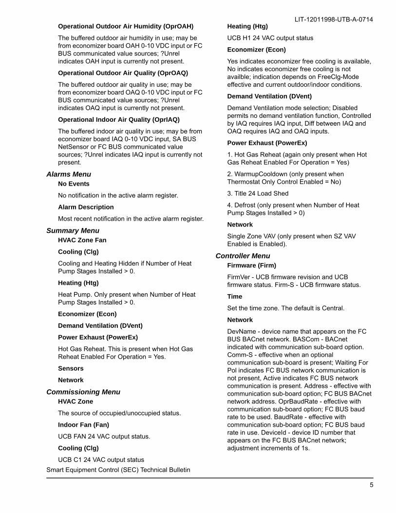
LIT-12011998-UTB-A-0714Operational Outdoor Air Humidity (OprOAH)
The buffered outdoor air humidity in use; may be from economizer board OAH 0-10 VDC input or FC BUS communicated value sources; ?Unrel indicates OAH input is currently not present.
Operational Outdoor Air Quality (OprOAQ)
The buffered outdoor air quality in use; may be from economizer board OAQ 0-10 VDC input or FC BUS communicated value sources; ?Unrel indicates OAQ input is currently not present.
Operational Indoor Air Quality (OprIAQ)
The buffered indoor air quality in use; may be from economizer board IAQ 0-10 VDC input, SA BUS NetSensor or FC BUS communicated value sources; ?Unrel indicates IAQ input is currently not present.
Alarms MenuNo Events
No notification in the active alarm register.
Alarm Description
Most recent notification in the active alarm register.
Summary MenuHVAC Zone Fan
Cooling (Clg)
Cooling and Heating Hidden if Number of Heat Pump Stages Installed > 0.
Heating (Htg)
Heat Pump. Only present when Number of Heat Pump Stages Installed > 0.
Economizer (Econ)
Demand Ventilation (DVent)
Power Exhaust (PowerEx)
Hot Gas Reheat. This is present when Hot Gas Reheat Enabled For Operation = Yes.
Sensors
Network
Commissioning MenuHVAC Zone
The source of occupied/unoccupied status.
Indoor Fan (Fan)
UCB FAN 24 VAC output status.
Cooling (Clg)
UCB C1 24 VAC output status
Heating (Htg)
UCB H1 24 VAC output status
Economizer (Econ)
Yes indicates economizer free cooling is available, No indicates economizer free cooling is not availble; indication depends on FreeClg-Mode effective and current outdoor/indoor conditions.
Demand Ventilation (DVent)
Demand Ventilation mode selection; Disabled permits no demand ventilation function, Controlled by IAQ requires IAQ input, Diff between IAQ and OAQ requires IAQ and OAQ inputs.
Power Exhaust (PowerEx)
1. Hot Gas Reheat (again only present when Hot Gas Reheat Enabled For Operation = Yes)
2. WarmupCooldown (only present when Thermostat Only Control Enabled = No)
3. Title 24 Load Shed
4. Defrost (only present when Number of Heat Pump Stages Installed > 0)
Network
Single Zone VAV (only present when SZ VAV Enabled is Enabled).
Controller Menu Firmware (Firm)
FirmVer - UCB firmware revision and UCB firmware status. Firm-S - UCB firmware status.
Time
Set the time zone. The default is Central.
Network
DevName - device name that appears on the FC BUS BACnet network. BASCom - BACnet indicated with communication sub-board option. Comm-S - effective when an optional communication sub-board is present; Waiting For Pol indicates FC BUS network communication is not present, Active indicates FC BUS network communication is present. Address - effective with communication sub-board option; FC BUS BACnet network address. OprBaudRate - effective with communication sub-board option; FC BUS baud rate to be used. BaudRate - effective with communication sub-board option; FC BUS baud rate in use. DeviceId - device ID number that appears on the FC BUS BACnet network; adjustment increments of 1s.
Smart Equipment Control (SEC) Technical Bulletin
5

LIT-12011998-UTB-A-0714
Miscellaneous (Misc)
Language - laguage used in the UCB parameter display. Units - IP uses Imperial units of measure in the UCB parameter display (°F, "wc, etc.), SI uses metric units of measure in the UCB parameter display (°C, kPA, etc.).
System Controllers (SysCntlrs)
The update menus displays the following information: Misc - Relearn, #NetSensors, EconCntlr, 4StgCntlr, FDDMCntlr and FDDSCntlr. UCB - UCB firmware revision, UCB software application revision and UCB hardware revision. Econ - economizer board firmware revision, economizer board software application revision and economizer board hardware revision.
Update MenuThe update menus displays the following information: View Version (ViewVer), Load Firmware (LoadFirm), Backup, Restore, Full Clone, Part Clone, Factory Default (FactryDft), Date and Time (DateTime) also can Export Trends to a USB Stick. Use the flash drive to save settings and update the control.
Details MenuUnit
The unit menu displays the name, model number, serial number, and reset lockout (ResetLO). The control name, model number, and serial number have a 14-character maximum. The default setting for the ResetLO is On. This resets all active hard lockout alarms.
Setpoints
This menu displays the current values for all the setpoints in use.
Zone
This menu displays all the current values for either the indoor or outdoor zone.
Control
This menu lists all the current values for the control; indoor fan, cooling (Clg), heating (Htg), heat pump, economizer, power exhaust, demand ventilation, air monitoring station, hot gas reheat and smoke control.
Service
This menu lists the current information for the inputs which includes: sensors, coil sensors, thermostat, binary inputs, unit protection, and network inputs. Information for the outputs both relay and analog. The Factory options displays the current control configuration data (for example, cooling stages set to 2, no heating stages).
Self Test
This menu contains the controls to execute a diagnostic test for the rooftop equipment.
View Results
This menu lists the results of the Self Test and can be used to identify any equipment failures.
Detailed ProceduresTurning On the Unit1. After you apply 24 VAC power to the C and 24V
terminals, the UCB begins the startup sequence. The display backlight lights and begins to scroll Johnson Controls, JCI. The power LED lights up and remains lit.
2. The Red FAULT LED lights up and flashes intermittently thereafter. The green SA Bus LED briefly lights up.
3. The local display begins a countdown sequence after power is applied. During the countdown sequence the green SA Bus LED does one of the two following actions:
a. lights to indicate the UCB is awaiting communi-cation from SA Bus devices, such as the econo-mizer board or network sensor or
b. flashes to indicate the UCB established commu-nication with SA Bus devices.
4. 4.The local display is blank with the completion of a successful boot-up sequence. Use the joystick to navigate to the menu options.
Active Alarms when Turning On the Unit1. When alarms are active after the startup sequence,
the display shows #1 text on the top line and scrolls the most recent alarm on the bottom line.
2. If more than one alarm is active, the display scrolls through each alarm in the active alarm register. The display shows up to five alarms scrolling through each from most recent alarm to oldest alarm.
Smart Equipment Control (SEC) Technical Bulletin
6
LIT-12011998-UTB-A-0714
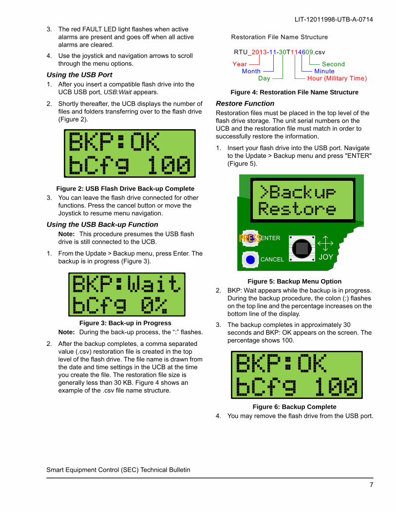
3. The red FAULT LED light flashes when active alarms are present and goes off when all active alarms are cleared.
4. Use the joystick and navigation arrows to scroll through the menu options.
Using the USB Port1. After you insert a compatible flash drive into the
UCB USB port, USB:Wait appears.
2. Shortly thereafter, the UCB displays the number of files and folders transferring over to the flash drive (Figure 2).
Figure 2: USB Flash Drive Back-up Complete
3. You can leave the flash drive connected for other functions. Press the cancel button or move the Joystick to resume menu navigation.
Using the USB Back-up FunctionNote: This procedure presumes the USB flash drive is still connected to the UCB.
1. From the Update > Backup menu, press Enter. The backup is in progress (Figure 3).
Figure 3: Back-up in Progress
Note: During the back-up process, the “:” flashes.
2. After the backup completes, a comma separated value (.csv) restoration file is created in the top level of the flash drive. The file name is drawn from the date and time settings in the UCB at the time you create the file. The restoration file size is generally less than 30 KB. Figure 4 shows an example of the .csv file name structure.
Figure 4: Restoration File Name Structure
Restore FunctionRestoration files must be placed in the top level of the flash drive storage. The unit serial numbers on the UCB and the restoration file must match in order to successfully restore the information.
1. Insert your flash drive into the USB port. Navigate to the Update > Backup menu and press "ENTER" (Figure 5).
Figure 5: Backup Menu Option
2. BKP: Wait appears while the backup is in progress. During the backup procedure, the colon (:) flashes on the top line and the percentage increases on the bottom line of the display.
3. The backup completes in approximately 30 seconds and BKP: OK appears on the screen. The percentage shows 100.
Figure 6: Backup Complete
4. You may remove the flash drive from the USB port.
Restoration File Name Structure
RTU_2013-11-30T114609.csv
YearMonth
Day Hour (Military Time)Minute
Second
ENTER
CANCEL JOY
PRESSPRESS
Smart Equipment Control (SEC) Technical Bulletin
7

LIT-12011998-UTB-A-0714
After the backup completes, a comma separated value (.csv) restoration file is created in the top level of the flash drive. The file name is drawn from the date and time settings in the UCB at the time you create the file. The restoration file size is generally less than 30 KB. Figure shows an example of the .csv file name structure.
Failed Restore Attempt If the USB drive is removed before the firmware upload is allowed to complete it will require that the user perform two updates/upload procedures to successfully complete and update all the necessary files. If power is lost during the upload process the user will only be required to repeat only one update/upload procedure.
Updating SSE Software1. A USB Flash Drive must be plugged into the UCB. It
must contain the appropriate software file (ending in “.pkg”). This is at the top level of the flash drive.
2. On the UCB, at the display, push the joystick “down” until the display has a line showing: >Update.
Figure 7: Display Update
3. Push the "ENTER" button. The first line should now display: >View Ver.
• If you want to verify the version in the UCB, push the"ENTER" button now. The current version will be dis-played. Push the Cancel button to return to display-ing ">Update"
4. Push the joystick down until the display is showing: >Backup
5. Push the "ENTER" button. Wait until the top line says "BKP: OK" and the second line says 100%
6. Push the Cancel button. The display should now show: >Update
7. Push the "ENTER" button. The display should now show: >View Ver
8. Push the joystick down. The first line should now display: >LoadFirm
9. Push the "ENTER" button. The top line should display: >1.0.0.1101.secusb.pkg or the current firmware version.
10. If not, push the joystick down (or up) so the carrot (>) points to the appropriate file
11. Push the "ENTER" button. Push again to Confirm.
12. The UCB and economizer will now be reprogrammed with the selected software, if they are different. Wait until the everything is complete, and the control has done a Restart (as if power was just applied).
13. On the UCB, at the display, push the joystick "down" until the display has a line showing: >Update
14. Push the "ENTER" button. The first line should now display: >View Ver
15. Push the joystick down until the display is showing: >Restore
16. Push the "ENTER" button.
17. Push the joystick down until the display line starts with: >RTUxxxx and ends with .csv
18. The UCB will now read back the stored setup. When it is done, the control will Restart. When that is complete, the new software version will be running.Push the "ENTER" button. Push again to Confirm.
Note: If the software update fails, reset the unit and perform the upgrade again.
Read The Version On The Economizer1. With Econ and UCB attached together (see Step 1
above).
2. Push the joystick "down" (or up, if you go past) until the display shows: >Controller
Figure 8: Display Update
3. Push the "ENTER" button. The first line should now display: >Firm
4. Push the joystick down until the display shows: >SysCntlrs
5. Push the "ENTER" button. The first line should now display: >Misc
6. Push the joystick down until the display shows: >Econ
7. Push the "ENTER" button. The first line should now display: >EconMainVer
8. Push the "ENTER" button again. The second line should now display the version of software installed in the Economizer.
Smart Equipment Control (SEC) Technical Bulletin
8

LIT-12011998-UTB-A-0714
Alarm Appendix
Alarm List
Alarms are categorized into three groups based on severity: critical, service priority, and service. Table 2 describes the alarm.
Table 2: AlarmsSeverity Alarm How It Happens
Critical C1 Locked Out Due to High Pressure Three HPS1 trips within two hours.
C2 Locked Out Due to High Pressure Three HPS2 trips within two hours.
C3 Locked Out Due to High Pressure Three HPS3 trips within two hours.
C4 Locked Out Due to High Pressure Three HPS4 trips within two hours.
C1 Locked Out Due to Low Pressure Three LPS1 trips within one hour.
C2 Locked Out Due to Low Pressure Three LPS2 trips within one hour.
C3 Locked Out Due to Low Pressure Three LPS3 trips within one hour.
C4 Locked Out Due to Low Pressure Three LPS4 trips within one hour.
C1 Locked Out Due to Coil Freeze Three FS1 trips within two hours. (Evap Coil Temp < Evap Coil Temp Cutout SP)
C2 Locked Out Due to Coil Freeze Three FS2 trips within two hours.(Evap Coil Temp < Evap Coil Temp Cutout SP)
C3 Locked Out Due to Coil Freeze Three FS3 trips within two hours.(Evap Coil Temp < Evap Coil Temp Cutout SP)
C4 Locked Out Due to Coil Freeze Three FS4 trips within two hours.(Evap Coil Temp < Evap Coil Temp Cutout SP)
Exhaust Fan VFD Failure EX VFD BI trips (must be set up as Exhaust or Variable Frequency Fan)
HS1 Locked Out Due to Limit Switch Three LS1 trips within one hour.
HS2 Locked Out Due to Limit Switch Three LS2 trips within one hour.
HS3 Locked Out Due to Limit Switch Three LS3 trips within one hour.
Unit Shutdown Due to Smoke, etc. SD input loses 24 VAC.
Supply Fan VFD Failure Fan VFD Input trips (must be set up as NOT Single Speed)
No Heat-Cool Due to Unreliable Space-T Input Unreliable
4-Stage Communication Failure 4-Stage board goes from Online to Offline.
Economizer Communication Failure Economizer board goes from Online to Offline.
Outputs Disabled Due to Low Input V Blackout Conditions
Outputs Limited Due Brownout Input V Brownout Conditions
Unit Locked Out Due to APS Three APS trips within 1.5 hours.(if APS is installed or based on Duct Pressure if Variable Speed Fan enabled).
Unit Locked Out Due to Supply Fan OL Three FAN OVR trips within two hours.
Unit Locked Out Due to High Duct-P Duct Static Pressure is greater than the High Duct Static Pressure Setpoint.
Service Priority
Evaporator Coil Temp 1 Sensor Failure Input unreliable and Number of Cooling Stages >= 1
Condenser Coil Temp 1 Sensor Failure Input unreliable and Number of Cooling Stages >= 1
Evaporator Coil Temp 2 Sensor Failure Input unreliable and Number of Cooling Stages >= 2
Condenser Coil Temp 2 Sensor Failure Input unreliable and Number of Cooling Stages >= 2
Smart Equipment Control (SEC) Technical Bulletin
9

LIT-12011998-UTB-A-0714
Service Priority (Continued)
Evaporator Coil Temp 3 Sensor Failure Input unreliable and Number of Cooling Stages >= 3
Condenser Coil Temp 3 Sensor Failure Input unreliable and Number of Cooling Stages >= 3
Evaporator Coil Temp 4 Sensor Failure Input unreliable and Number of Cooling Stages >= 4
Condenser Coil Temp 4 Sensor Failure Input unreliable and Number of Cooling Stages >= 4
Building Pressure Sensor Failure Input unreliable
Outdoor Air Temperature Sensor Failure Input unreliable
Return Air Temperature Sensor Failure Input unreliable and Variable Speed Fan
Supply Air Temperature Sensor Failure Input Unreliable AND (Econ Comm Status = Online OR Mixed Air Sequencer = DAT Control)
Unit Shutdown Due to Supply Fan Overload FAN OVR Trip (but less than three in one hour as that would cause 'Unit Locked Out Due to Supply Fan OL')
Main Controller Calibration Error Missing Cal Data
FDDM Controller Calibration Error Missing Cal Data
Econ Controller Calibration Error Missing Cal Data
4-Stage Controller Calibration Error Missing Cal Data
Unit Shutdown Due to Air Proving Switch Cmd but no proof for >= 90 seconds (if this happens less than three in 1.5 hours; otherwise that would cause 'Unit Locked Out Due to APS')
FDDS Controller Calibration Error Missing Cal Data
Service
Duct Pressure Sensor Failure Input Unreliable and Variable Speed Fan
Return Air Humidity Sensor Failure Input unreliable
Outdoor Air Humidity Sensor Failure Input unreliable
Supply Humidity Sensor Failure Input unreliable
Indoor Air Quality Sensor Failure Input unreliable
Outdoor Air Quality Sensor Failure Input unreliable
Fresh Air Intake Sensor Failure Input unreliable
Mixed Air Temp Sensor Failure Input unreliable
Space Indoor temp Sensor Failure Input unreliable
Space Offset Sensor Failure Input unreliable
C1 Shutdown Due to High Pressure HPS1 Trip
C2 Shutdown Due to High Pressure HPS2 Trip
C3 Shutdown Due to High Pressure HPS3 Trip
C4 Shutdown Due to High Pressure HPS4 Trip
C1 Shutdown Due to Low Pressure LPS1 Trip
C2 Shutdown Due to Low Pressure LPS2 Trip
C3 Shutdown Due to Low Pressure LPS3 Trip
C4 Shutdown Due to Low Pressure LPS4 Trip
C1 Shutdown Due to Coil Freeze FS1 Trip (Evap Coil Temp < Evap Coil Temp Cutout SP)
C2 Shutdown Due to Coil Freeze FS2 Trip (Evap Coil Temp < Evap Coil Temp Cutout SP)
C3 Shutdown Due to Coil Freeze FS3 Trip (Evap Coil Temp < Evap Coil Temp Cutout SP)
C4 Shutdown Due to Coil Freeze FS4 Trip (Evap Coil Temp < Evap Coil Temp Cutout SP)
Table 2: Alarms (Continued)
Severity Alarm How It Happens
Smart Equipment Control (SEC) Technical Bulletin
10

LIT-12011998-UTB-A-0714
Smart Equipment Control (SEC) Technical Bulletin
Service (Continued)
Low Outdoor Air Temp Cooling Cutout OAT < OAT Cooling Cutout
Econ Economizing When it Should Not Economizer Damper % Command > Min OA Position + FDD Damper Min Position Tolerance
Econ Not Economizing When It Should Economizer Damper % Command < Min OA Position + FDD Damper Min Position Tolerance
Economizer Damper Not Modulating ABS(Economizer Damper % Command - Economizer Damper Position) > FDD Economizer Damper Allowed Error
Economizer Letting In Excess Outdoor Air (Economizer Damper % Command > Min OA Position + FDD Damper Min Position Tolerance AND Ramp Min OA) OR(Economizer Damper % Command > FDD Damper Min Position Tolerance AND Ramp Closed)
HS1 Shutdown Due to Limit Switch LS1 Trip
HS2 Shutdown Due to Limit Switch LS2 Trip
HS3 Shutdown Due to Limit Switch LS3 Trip
HS1 Off Due to Gas Valve H1 with no GV1 for >=6 minutes
HS2 Off Due to Gas Valve H2 with no GV2 for >=6 minutes
HS3 Off Due to Gas Valve H3 with no GV3 for >=6 minutes
Dirty Filter DFS Trip
FDD 1 Communication Failure FDD Master Online -> Offline
FDD 2 Communication Failure FDD Slave Online -> Offline
Unit has Received a Purge Request PURGE-S on Econ trip
Excessive Supply Air Temp Cooling SAT < Excessive SAT Cooling Sp AND SAT Limit for Cooling Enable
HS1 Gas Valve Failure GV1 on without H1 for >= 5 seconds
HS2 Gas Valve Failure GV2 on without H2 for >= 5 seconds
HS3 Gas Valve Failure GV3 on without H3 for >= 5 seconds
Excessive Supply Air Temp Heating SAT > Excessive SAT Heating SP AND SAT Air Temp Limit for Heat Enabled
Space Temperature Cooling Alarm Space Temp > Operating Cooling SP for more than 60 minutes
C1 Refrigerant Flow Restriction FDD Alarm, see Table 3.
Hot H20 FS Open to Prevent Coil Freeze Hydronic Heating Enabled and (HW Freeze BI trip and Unreliable OAT) or HW Freeze BI trip and OAT is less than 40°F
Hot H20 FS Opened When It Should Not Hydronic Heating Enabled and OAT is greater than 40°F and HW Freeze BI trip
Space Temperature Heating Alarm Space Temp is less than Operating Heating SP for more than 60 minutes.
Not Economizing - No Supply Air Sensor Free Cooling Available and MA Sequencer = DAT Control and SAT Unreliable orSAT Unrealiable and MA Sequence = Zone Control and MA State = Mech and Free Cooling Available or Tstat Only and Mech and Free Cooling Available
Using Return Instead of Space Temp Effective Zone Source = Return Air Temp and Not TStat Only
Air Proving Switch is Stuck Closed APS is closed, but fan command is not given
Table 2: Alarms (Continued)
Severity Alarm How It Happens
11

LIT-12011998-UTB-A-0714
Smart Equipment Control (SEC) Technical Bulletin
FDD UnderstandingFault Detection Diagnostics is the integral tool to maintaining HVAC systems at their optimal performance and reliability. In addition, FDD supports continuous commissioning through its continuous performance monitoring functionality. Studies indicate that the use of FDD can result in 10-30% energy savings on an ongoing basis, support efficient maintenance practices, extend equipment life, and provide more consistent occupant comfort and indoor air quality.
For past ten years outside of Johnson Controls, other studies and implementation of FDD have been more in a central tool format. Today we are utilizing the JCI industry several years of experience and data collection and implementing new algorithms embedded into our SMART Equipment Control platform. These FDD are programmed and are continuously running within the Economizer section and refrigeration sections of Johnson Controls/York package equipment.
Definition of FDD is best described as Fault Diagnosis which is pinpointing one or more root causes of problems, to the point where corrective action can be taken. Some also call this as "fault isolation". This does emphasizes the distinction from fault isolation vs. fault detection. In a most common terminology "fault diagnosis" often includes fault detection, so "fault isolation" emphasizes the distinction.
Detection + Isolation = Diagnosis (FDD)
Equipment layer within the Smart Building architecture is a key to our SMART Equipment FDD intelligence. It is a foundation of providing key information of the equipment and providing that information through out the system for further evaluations and actions. When we have FDD embedded at the equipment level, which has intelligence the advantage is the complete access to internal state of the equipment and it can behave in real time. This is epically important when the algorithms are focused around refrigeration circuits. Continuous changes in data point and thermodynamics of the equipment is very challenging to identity and isolate the refrigeration problems. Having FDD this close to the equipment will create a much precise and accurate information with the outcome of lowering energy cost, operating cost and increasing comfort level.
Some key advantages of embedded FDD at equipment layer are:
1. Visibility to performance of all unit components and how they interact together (e.g. fully integrated economizer control, simultaneous heating and cooling, low refrigerant, foul tubes, etc..)
2. Excellent place to insert unit-level performance models and analytical algorithms in the factory (e.g. overall unit control expectations)
Current FDD option for Johnson Controls/York Package Equipment:
Description
The SE-FDD1001-0 Fault Detection Diagnostics (FDD) board is new and unique for the light commercial product lines. The FDD controller lets the package equipment to predict faults before they become a major failure, cause comfort issues, or result in efficiency problems. Embedded algorithms continuously run within the FDD controller. The algorithms monitor the types of inputs, to precisely indicate the faults and recommend how to correct them. This new innovative feature comes optional with the Smart Equipment Controls (SEC) product line for Series 5 to 40, as well as the new Series 12R. The FDD controller meets all of the pending California Energy Code Regulations (Title 24).The FDD controller meets all of the pending California Energy Code Regulations (Title 24) for rooftop units (RTU) with an enabled economizer.
During the startup process, the FDD controller calculates the efficiency and capacity of the equipment, and generates a baseline for future measurements. The algorithms provide this type of information during the equipment life cycle. You can view this information from the unit control board (UCB) local display, Mobile Access Portal (MAP), or through a building management system (BMS) connection. These two indices's, efficiency and capacity, enable you to make smart decisions regarding your equipment. You can quickly and easily see when it is not performing at the baseline efficiency level.
Refer to the Smart Equipment Controls (SEC) Product Bulletin (LIT-12011934) for important product application information.
12

LIT-12011998-UTB-A-0714
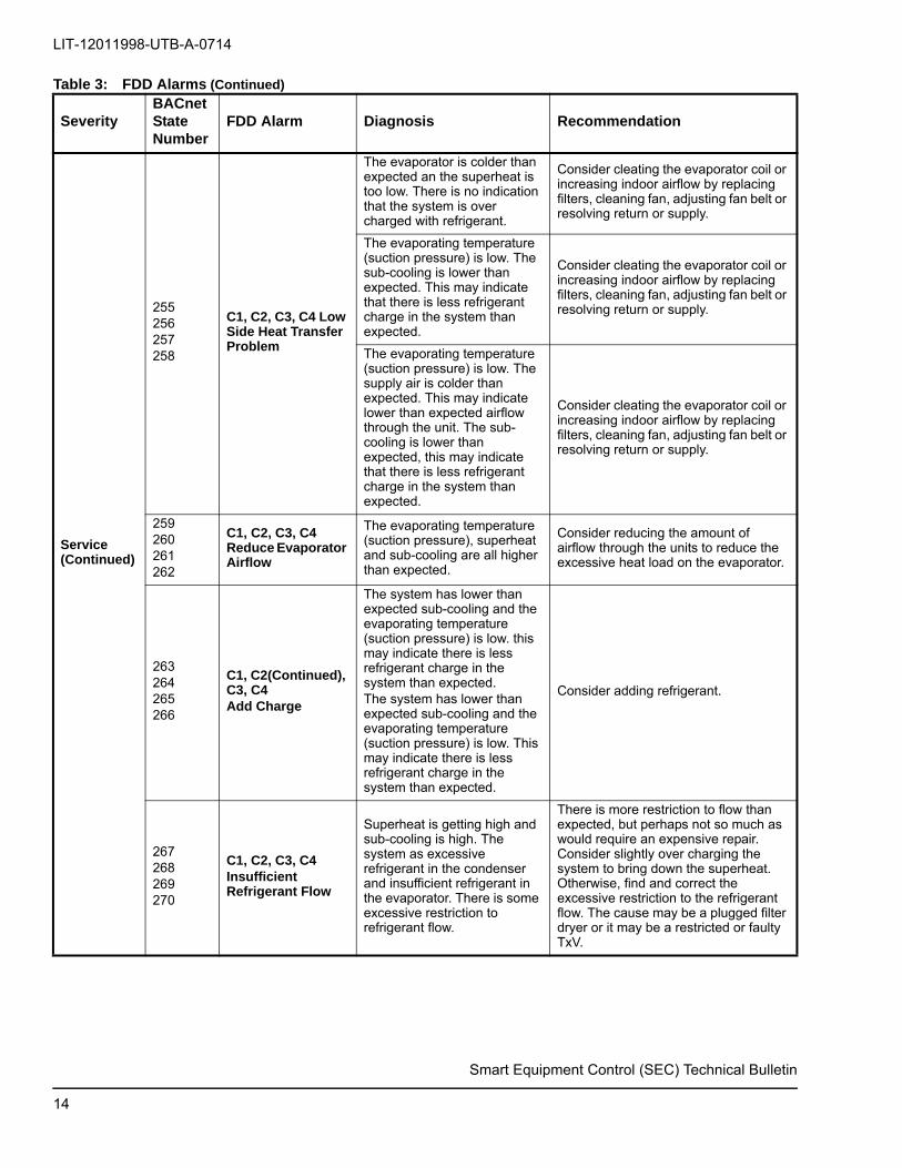
Table 3: FDD Alarms
SeverityBACnet StateNumber
FDD Alarm Diagnosis Recommendation
Service
235236237238
C1, C2, C3, C4 Refrigerant Low
The system has lower than expected sub-cooling. This may indicate there is less refrigerant charge in the system than expected.
Consider adding refrigerant.
239240241242
C1, C2, C3, C4 Excessive Refrigerant Flow
The low side pressure is high, the superheat is low, and the sub-cooling is low. There is excessive refrigerant flow into the evaporator. The superheat is low with a TxV unit. There is excessive refrigerant flow into the evaporator.
The TxV is overfeeding the refrigerant into the evaporator. One possible cause is something may be holding the TxV open when conditions would cause it to close, if it were functioning properly.
243244245246
C1, C2, C3, C4 Inefficient Compressor
The low side pressure is far higher than would be expected in a normally operating system. The compressor appears to have lost significant pumping capacity.
If the compressor is a scroll compressor, consider reversing the direction of rotation. If the compressor cannot pump refrigerant at its design capacity, the compressor needs to be replaced.
247248249250
C1, C2, C3, C4 Refrigerant Flow Restriction
Superheat is high and sub-cooling is high. The system has excessive refrigerant in the condenser and insufficient refrigerant in the evaporator. There is an excessive restriction to refrigerant flow.
Find and correct the excessive restriction to the refrigerant flow. The cause may be a plugged filter drier or it may be a restricted or faulty TxV.
ET is low and SH and SC ore high and COA is greater than goal and not high.
There is a refrigerant flow restriction combined with either an over charged system or a dirty condenser or inoperable condenser fan.
ET is low and SH and SC are high and COA is high
There is a refrigerant flow restriction combined with either an over charged system or a dirty condenser or inoperable condenser fan.
251252253254
C1, C2, C3, C4High Side Heat Transfer Problem
Condenser is hot and there is not indication of over charge. Also consider doing a standing pressure test for non-condensable to explain these results.
It is difficult for the condenser to reject heat. Possible causes include a dirty condenser coil or a condenser fan problem. Also consider doing a standing pressure test for non-condensable to explain these results.
Smart Equipment Control (SEC) Technical Bulletin
13
LIT-12011998-UTB-A-0714
Smart Equipment Control (SEC) Technical Bulletin
Service(Continued)
255256257258
C1, C2, C3, C4 Low Side Heat Transfer Problem
The evaporator is colder than expected an the superheat is too low. There is no indication that the system is over charged with refrigerant.
Consider cleating the evaporator coil or increasing indoor airflow by replacing filters, cleaning fan, adjusting fan belt or resolving return or supply.
The evaporating temperature (suction pressure) is low. The sub-cooling is lower than expected. This may indicate that there is less refrigerant charge in the system than expected.
Consider cleating the evaporator coil or increasing indoor airflow by replacing filters, cleaning fan, adjusting fan belt or resolving return or supply.
The evaporating temperature (suction pressure) is low. The supply air is colder than expected. This may indicate lower than expected airflow through the unit. The sub-cooling is lower than expected, this may indicate that there is less refrigerant charge in the system than expected.
Consider cleating the evaporator coil or increasing indoor airflow by replacing filters, cleaning fan, adjusting fan belt or resolving return or supply.
259260261262
C1, C2, C3, C4 Reduce Evaporator Airflow
The evaporating temperature (suction pressure), superheat and sub-cooling are all higher than expected.
Consider reducing the amount of airflow through the units to reduce the excessive heat load on the evaporator.
263264265266
C1, C2(Continued), C3, C4Add Charge
The system has lower than expected sub-cooling and the evaporating temperature (suction pressure) is low. this may indicate there is less refrigerant charge in the system than expected.The system has lower than expected sub-cooling and the evaporating temperature (suction pressure) is low. This may indicate there is less refrigerant charge in the system than expected.
Consider adding refrigerant.
267268269270
C1, C2, C3, C4Insufficient Refrigerant Flow
Superheat is getting high and sub-cooling is high. The system as excessive refrigerant in the condenser and insufficient refrigerant in the evaporator. There is some excessive restriction to refrigerant flow.
There is more restriction to flow than expected, but perhaps not so much as would require an expensive repair. Consider slightly over charging the system to bring down the superheat. Otherwise, find and correct the excessive restriction to the refrigerant flow. The cause may be a plugged filter dryer or it may be a restricted or faulty TxV.
Table 3: FDD Alarms (Continued)
SeverityBACnet StateNumber
FDD Alarm Diagnosis Recommendation
14

LIT-12011998-UTB-A-0714
Smart Equipment Control (SEC) Technical Bulletin
Service(Continued)
271272273274
C1, C2, C3, C4Recover Charge
The system has higher than expected subcooling. This may indicate there is more refrigerant charge in the system than expected.
Consider recovering refrigerant.
The system has higher than expected subcooling and the condensing temperature (discharge pressure) is higher than expected at the ambient temperature. This may indicate there is more refrigeratnt charge in the system than expected.
Consider recovering refrigerant.
Superheat is getting high and subcooling is high. The system has excessive refrigerant in the condenser and insufficient refrigerant in the evaporator. This is some excessive restriction to refrigerant flow.
There is more restriction to flow than expected, but perhaps not so much as would require an expensive repair. Consider slightly over charging the system to bring down the superheat. Otherwise, find and correct the excessive restriction to refrigerant flow. The cause may be a plugged filter dryer or it may be a restricted or faulty TxV.
299300301302
C1, C2, C3, C4Non-Condensables Present
199200201202
C1, C2, C3, C4Liquid Temp Greater Than Cond Temp
Check LT>CT sensors. If confident in SP and ST sensors, add charge.
Table 3: FDD Alarms (Continued)
SeverityBACnet StateNumber
FDD Alarm Diagnosis Recommendation
15

LIT-12011998-UTB-A-0714
Smart Equipment Control (SEC) Technical Bulletin
Service(Continued)
171172173174
C1, C2, C3, C4Basic Data Not Available
An important sensor measurement is not available. Potential sensors include: SP, LP or DP, ST, LT, AMB, RWB, RA or RAH. Find which data point is not being collected and resolve the problem. Diagnostics should function thereafter.
Minimum sensor input data is not available. (SP, LP or DP, ST, LT, AMB, RWB or RA/RAH)
The return air web bulb temperature measurement is not available. Find the cause of the missing data and resolve the problem. Diagnostics should function thereafter.
Return air web-bulb temperature is not available.
The return air temperature and humidity measurement are not available. Find the cause of the missing data and resolve the problem. Diagnostics should function thereafter.
Return air temperature and return air humidity are not available.
The return air temperature measurement is not available. Find the cause of the issue and resolve the problem. Diagnostics should function thereafter.
Return air temperature is not available.
303304305306
C1, C2, C3, C4Unit Off
The compressor appears to not be running because of the differences in the suction and liquid pressures are too small to prove operation, or the compressor has nearly no pumping capacity.
The pressure difference is not large enough to make the condensing temperature more than 20°F above the evaporating temperature.
175176177178
C1, C2, C3, C4Return Air Wet-Bulb Temp Out of Range
For fixed orifice only
The valid range of ambient temperature in the charge chart is between 55 to 115°F. The target superheat value is not available.
179180181182
C1, C2, C3, C4Ambient Temp Too Low
The measured ambient temperature ins either less than 55°F, a limit in the diagnostic software, the sensor placement is incorrect, reading a low temperature or there is a faulty ambient temperature sensor.
The ambient temperature is too low to make reasonable diagnosis.
Table 3: FDD Alarms (Continued)
SeverityBACnet StateNumber
FDD Alarm Diagnosis Recommendation
16

LIT-12011998-UTB-A-0714
Smart Equipment Control (SEC) Technical Bulletin
Service(Continued)
183184185186
C1, C2, C3, C4Ambient Temp Too High
The measured ambient temperature is either over 115°F, a limit in the diagnostic software or the sensor placement is incorrect, reading a high temperature or there is a faulty ambient temperature sensor.
The ambient temperature is too high to make reasonable diagnosis.
187188189190
C1, C2, C3, C4Return Air Wet-Bulb Temp Too Low
The return air wet bulb temperature or the return air dry bulb temperature measurement is not valid. The current reading indicated the relative humidity is less than zero. Find the cause of the invalid data and resolve the problem in order for diagnostics to function.
The RWB is lower than RWB corresponding to 0% RAH for given RA.
191192193194
C1, C2, C3, C4Return Air Wet-Bulb Temp Too High
The measured return air wet bulb temperature is either over 76°F, a limit in the diagnostic software, or the sensor placement is incorrectly reading a high humidity, or there is a faulty return wet bulb.
The RWB is either above 76°F or higher than the RWB corresponding to 95% RAH for given RA.
195196197198
C1, C2, C3, C4Condensing Temp Less Than Ambient
The condensing temperature is below the ambient temperature. This indicates either the ambient sensor placement is incorrect, reading a high temperature, there is a faulty ambient temperature sensor or the condenser is wet and experiencing evaporative cooling.
The condensing temperature is below the ambient temperature. This indicates either a bad sensor or the information was not entered properly. Check the sensors and/or verify data was entered correctly.
203204205206
C1, C2, C3, C4Suction Temp Less Than Evap Temp
The suction temperature is less than the evaporator temperature. This indicates either the suction pressure or the suction line temperature or the refrigerant type expectation is invalid.
The suction temperature is below the evaporator temperature. This indicates either a bad sensor or the information was not entered properly. Check the sensor and/or verify the data was entered correctly.
207208209210
C1, C2, C3, C4Evap Temp Greater Than Ambient Temp
The evaporating temperature is above the ambient temperature. this indicates either a bad suction pressure sensor or ambient temperature sensor.
The evaporating temperature is above the ambient temperature. This indicates either a bad sensor or the information was not entered properly. Check the sensor and/or verity the data was entered correctly.
211212213214
C1, C2, C3, C4Liquid Temp Less Than Ambient Temp
The liquid temperature is below the ambient temperature. this indicates either a bad discharge pressure sensor or ambient temperature sensor.
The liquid temperature is below the ambient temperature. This indicates either a bad sensor or the information was not entered properly. Check the sensor and/or verity the data was entered correctly.
Table 3: FDD Alarms (Continued)
SeverityBACnet StateNumber
FDD Alarm Diagnosis Recommendation
17

LIT-12011998-UTB-A-0714
Smart Equipment Control (SEC) Technical Bulletin
Service(Continued)
215216217218
C1, C2, C3, C4Invalid Suction or Ambient Temp
ST is high compared to ambient.
219220221222
C1, C2, C3, C4Invalid RA Dry-Bulb or Wet-Bulb Temp
Diagnostic module detects that the return air wet bulb temperature is warmer than the return dry wet bulb temperature. Suspect sensors interchanged or one or both sensors are faulty. RWB is not less than RA.
223224225226
C1, C2, C3, C4Invalid Liquid and Suction Pressure
The diagnostic module has data indicating that the suction pressure is higher than the discharge pressure. There may be a faulty pressure sensor or the pressure sensors have been interchanged.
LP is less than SP. Verify that the liquid line pressure hose is connected to the liquid line pressure setting, and the suction pressure hose is connected to the suction line pressure setting.
227228229230
C1, C2, C3, C4Invalid Suction Temp
Tool set-up error, we don’t measure discharge temperature with a module.
ST is greater than Ct. Make sure the suction temperature sensor is not mounted on the discharge line.
279280281282
C1, C2, C3, C4Return Air Dry-Bulb Temp Too Low
The measured return air temperature in either less than 62°F, a limit in the diagnostic software or the sensor placement is incorrect, reading a low temperature or there is a faulty return air temperature sensor.
RA is too low for a reasonable diagnosis.
Table 3: FDD Alarms (Continued)
SeverityBACnet StateNumber
FDD Alarm Diagnosis Recommendation
18

LIT-12011998-UTB-A-0714
Smart Equipment Control (SEC) Technical Bulletin
Service(Continued)
283284285286
C1, C2, C3, C4Return Air Dry-Bulb Temp Too High
The measured return air temperature in either more than 84°F, a limit in the diagnostic software or the sensor placement is incorrectly reading a high temperature, or there is a faulty return air temperature sensor.
RA is too high for a reasonable diagnosis.
314315316317
C1, C2, C3, C4EI Below 75% Expected Performance
The efficiency of the system has degraded to a point where action is recommended. Efficiency is increased by reducing the high side pressure or increasing the low side pressure.
Efficiency index is below 75% of ideal.
275276277278
C1, C2, C3, C4CI Below 75% Expected Performance
The capacity of the system has degraded to a point where action is recommended. Capacity is increased by increasing the low side pressure or by reducing the superheat.
Capacity Index is below 75% of ideal.
322323324325
C1, C2, C3, C4EI+CI Below 75% Expected Performance
The efficiency and capacity o the system has degraded to a point where action is recommended. Efficiency is increased by reducing the high side pressure or increasing the low side pressure or by reducing the superheat.
Efficiency and Capacity Index are both below 75% of ideal.
287288289290
C1, C2, C3, C4FDD Not Functioning Sensor Unreliable
A local A1 reading is Unreliable (disconnected sensor). This error is on a per circuit basis.
291292293294
C1, C2, C3, C4FDD Not Monitoring ConditionsUnreliable
Error reading the RWB, RDB, or OAT information.
295296297298
C1, C2, C3, C4FDD Not Monitoring Equipment Data
There is an error with reading the equipment information.
Table 3: FDD Alarms (Continued)
SeverityBACnet StateNumber
FDD Alarm Diagnosis Recommendation
19

LIT-12011998-UTB-A-0714
Smart Equipment Control (SEC) Technical Bulletin
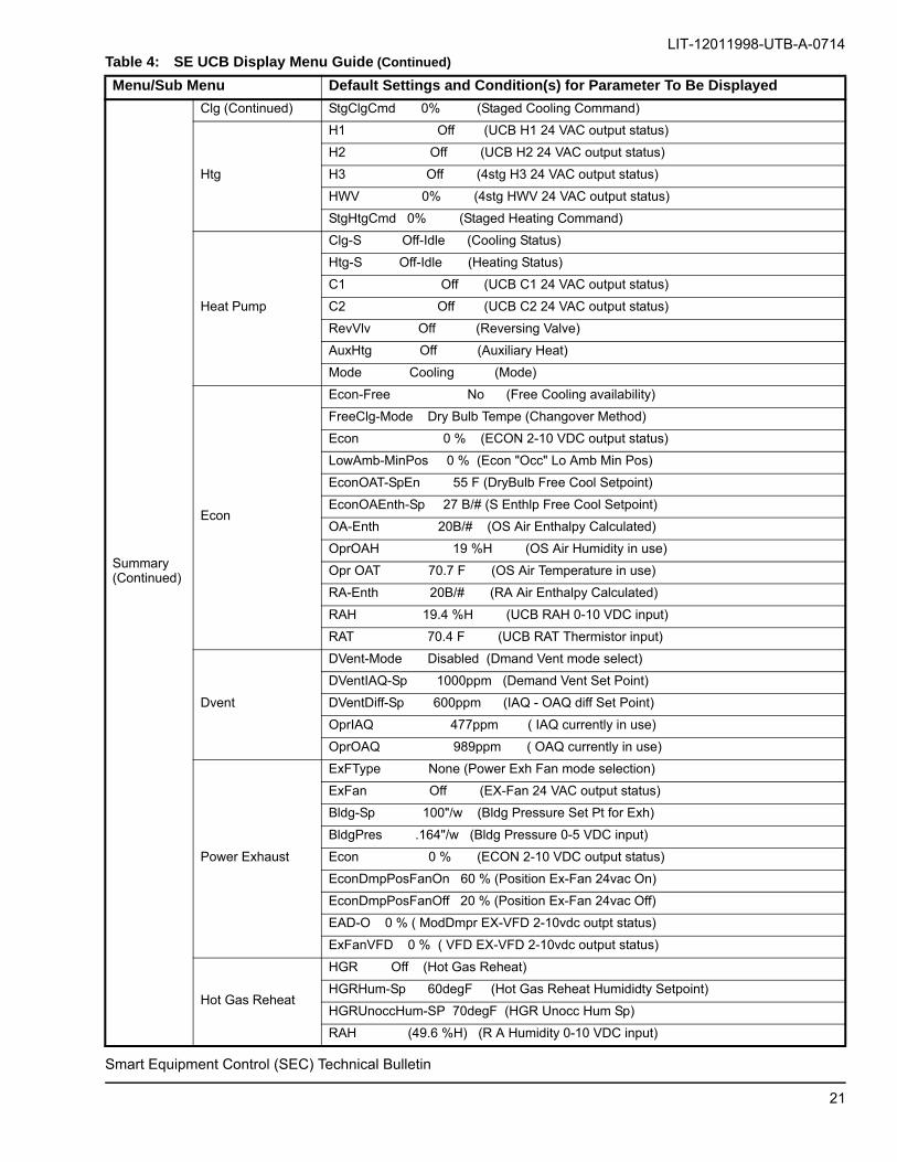
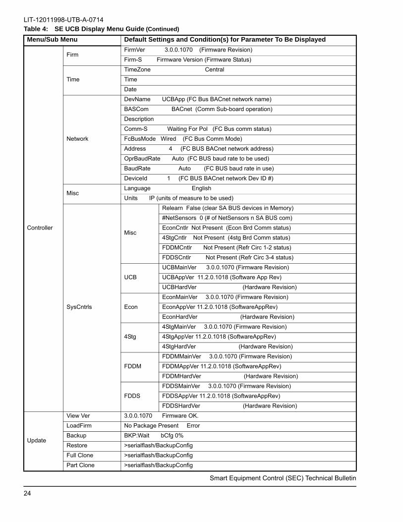
Table 4: SE UCB Display Menu Guide
Menu/Sub Menu Default Settings and Condition(s) for Parameter To Be Displayed
Status
Unit-S Idle (Unit Status)
Econ-S Disabled (Economizer Status)
ExF-S Off-Idle (Exhaust Fan Status)
Fan-S Off -Idle (Fan Status)
Clg-S Off-Idle (Cooling Status)
Htg-S Off-Idle (Heating Status)
HGR-S Off-Idle (Hot Gas Reheat Status)
DVent-Mode Disabled (Demand Vent Mode)
OprST (73.0 F) (Space Temperature Input)
SAT (60.7 F) (Supply Air Thermistor Input)
RAT (73.0 F) (Return Air Thermistor Input)
OprSH (49.6 %H) (Space Humidity Input)
RAH (49.6 %H) (Return Air Humidity Input)
OprOAT (73.0F) (Outdoor Air Temperature Input)
OprOAH (71 %H) (Outdoor Air Humidity Input)
OprOAQ (989ppm) (Outdoor Air Quality Input)
OprIAQ (477ppm) (Indoor Air Quality Input)
Alarms
No Events (No active alarm)
Alarm Description ( most recent Alarm)
Alarm Description (2nd most recent Alarm)
Alarm Description (3rd most recent Alarm)
Alarm Description (4th most recent Alarm)
Alarm Description (5th most recent Alarm)
Summary
HVAC Zone
OccSrc Local Input (Occ/UnOcc Status Source)
OprVAVClg-Sp 60 F (VAV Operating Cool Setpoint)
VAVOprHtg-Sp 68F (VAV Operating Heat Setpoint)
OprCVClg-Sp 72 F (CV - Operating Cool Setpoint)
CVOprHtg-Sp 68 F (CV - Operating Heat Setpoint)
OprSZVAVClg-Sp 72 F (SZ VAV Operating Clg Sp)
Opr ST 73.0 F (Space Temperature Input)
Opr SH 49.6 %H (Space Humidity Input)
OprIAQ 477ppm (Indoor Air Quality Input)
Fan
Fan (UCB FAN 24 VAC output status)
FanCtl-Type Single Speed (ID Blwr/Unit Op Mode)
FanOn Occ Yes (CV Constant Fan in Occupied Mode)
FanVFD 0 % (UCB VFD 2-10 VDC output status)
DctPrs-Sp 1.50"/w (VAV Supply Duct Press Setpt)
DctPrs 1.50"/w (VAV UCB Dct Prs 0-5 VDC input)
Clg
C1 Off (UCB C1 24 VAC output status)
C2 Off (UCB C2 24 VAC output status)
C3 Off (4stg C3 24 VAC output status)
C4 Off (4stg C4 24 VAC output status)
20
Smart Equipment Control (SEC) Technical Bulletin
LIT-12011998-UTB-A-0714
Summary (Continued)
Clg (Continued) StgClgCmd 0% (Staged Cooling Command)
Htg
H1 Off (UCB H1 24 VAC output status)
H2 Off (UCB H2 24 VAC output status)
H3 Off (4stg H3 24 VAC output status)
HWV 0% (4stg HWV 24 VAC output status)
StgHtgCmd 0% (Staged Heating Command)
Heat Pump
Clg-S Off-Idle (Cooling Status)
Htg-S Off-Idle (Heating Status)
C1 Off (UCB C1 24 VAC output status)
C2 Off (UCB C2 24 VAC output status)
RevVlv Off (Reversing Valve)
AuxHtg Off (Auxiliary Heat)
Mode Cooling (Mode)
Econ
Econ-Free No (Free Cooling availability)
FreeClg-Mode Dry Bulb Tempe (Changover Method)
Econ 0 % (ECON 2-10 VDC output status)
LowAmb-MinPos 0 % (Econ "Occ" Lo Amb Min Pos)
EconOAT-SpEn 55 F (DryBulb Free Cool Setpoint)
EconOAEnth-Sp 27 B/# (S Enthlp Free Cool Setpoint)
OA-Enth 20B/# (OS Air Enthalpy Calculated)
OprOAH 19 %H (OS Air Humidity in use)
Opr OAT 70.7 F (OS Air Temperature in use)
RA-Enth 20B/# (RA Air Enthalpy Calculated)
RAH 19.4 %H (UCB RAH 0-10 VDC input)
RAT 70.4 F (UCB RAT Thermistor input)
Dvent
DVent-Mode Disabled (Dmand Vent mode select)
DVentIAQ-Sp 1000ppm (Demand Vent Set Point)
DVentDiff-Sp 600ppm (IAQ - OAQ diff Set Point)
OprIAQ 477ppm ( IAQ currently in use)
OprOAQ 989ppm ( OAQ currently in use)
Power Exhaust
ExFType None (Power Exh Fan mode selection)
ExFan Off (EX-Fan 24 VAC output status)
Bldg-Sp 100"/w (Bldg Pressure Set Pt for Exh)
BldgPres .164"/w (Bldg Pressure 0-5 VDC input)
Econ 0 % (ECON 2-10 VDC output status)
EconDmpPosFanOn 60 % (Position Ex-Fan 24vac On)
EconDmpPosFanOff 20 % (Position Ex-Fan 24vac Off)
EAD-O 0 % ( ModDmpr EX-VFD 2-10vdc outpt status)
ExFanVFD 0 % ( VFD EX-VFD 2-10vdc output status)
Hot Gas Reheat
HGR Off (Hot Gas Reheat)
HGRHum-Sp 60degF (Hot Gas Reheat Humididty Setpoint)
HGRUnoccHum-SP 70degF (HGR Unocc Hum Sp)
RAH (49.6 %H) (R A Humidity 0-10 VDC input)
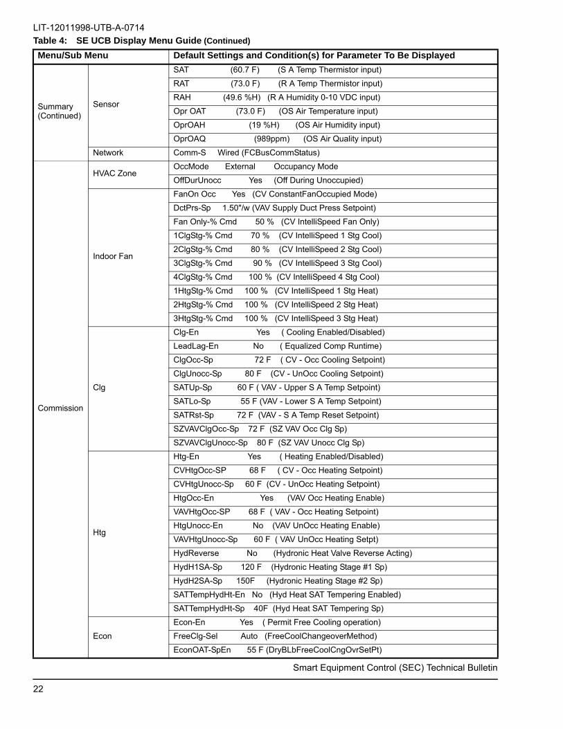
Table 4: SE UCB Display Menu Guide (Continued)
Menu/Sub Menu Default Settings and Condition(s) for Parameter To Be Displayed
21
LIT-12011998-UTB-A-0714
Summary (Continued)
Sensor
SAT (60.7 F) (S A Temp Thermistor input)
RAT (73.0 F) (R A Temp Thermistor input)
RAH (49.6 %H) (R A Humidity 0-10 VDC input)
Opr OAT (73.0 F) (OS Air Temperature input)
OprOAH (19 %H) (OS Air Humidity input)
OprOAQ (989ppm) (OS Air Quality input)
Network Comm-S Wired (FCBusCommStatus)
Commission
HVAC ZoneOccMode External Occupancy Mode
OffDurUnocc Yes (Off During Unoccupied)
Indoor Fan
FanOn Occ Yes (CV ConstantFanOccupied Mode)
DctPrs-Sp 1.50"/w (VAV Supply Duct Press Setpoint)
Fan Only-% Cmd 50 % (CV IntelliSpeed Fan Only)
1ClgStg-% Cmd 70 % (CV IntelliSpeed 1 Stg Cool)
2ClgStg-% Cmd 80 % (CV IntelliSpeed 2 Stg Cool)
3ClgStg-% Cmd 90 % (CV IntelliSpeed 3 Stg Cool)
4ClgStg-% Cmd 100 % (CV IntelliSpeed 4 Stg Cool)
1HtgStg-% Cmd 100 % (CV IntelliSpeed 1 Stg Heat)
2HtgStg-% Cmd 100 % (CV IntelliSpeed 2 Stg Heat)
3HtgStg-% Cmd 100 % (CV IntelliSpeed 3 Stg Heat)
Clg
Clg-En Yes ( Cooling Enabled/Disabled)
LeadLag-En No ( Equalized Comp Runtime)
ClgOcc-Sp 72 F ( CV - Occ Cooling Setpoint)
ClgUnocc-Sp 80 F (CV - UnOcc Cooling Setpoint)
SATUp-Sp 60 F ( VAV - Upper S A Temp Setpoint)
SATLo-Sp 55 F (VAV - Lower S A Temp Setpoint)
SATRst-Sp 72 F (VAV - S A Temp Reset Setpoint)
SZVAVClgOcc-Sp 72 F (SZ VAV Occ Clg Sp)
SZVAVClgUnocc-Sp 80 F (SZ VAV Unocc Clg Sp)
Htg
Htg-En Yes ( Heating Enabled/Disabled)
CVHtgOcc-SP 68 F ( CV - Occ Heating Setpoint)
CVHtgUnocc-Sp 60 F (CV - UnOcc Heating Setpoint)
HtgOcc-En Yes (VAV Occ Heating Enable)
VAVHtgOcc-SP 68 F ( VAV - Occ Heating Setpoint)
HtgUnocc-En No (VAV UnOcc Heating Enable)
VAVHtgUnocc-Sp 60 F ( VAV UnOcc Heating Setpt)
HydReverse No (Hydronic Heat Valve Reverse Acting)
HydH1SA-Sp 120 F (Hydronic Heating Stage #1 Sp)
HydH2SA-Sp 150F (Hydronic Heating Stage #2 Sp)
SATTempHydHt-En No (Hyd Heat SAT Tempering Enabled)
SATTempHydHt-Sp 40F (Hyd Heat SAT Tempering Sp)
Econ
Econ-En Yes ( Permit Free Cooling operation)
FreeClg-Sel Auto (FreeCoolChangeoverMethod)
EconOAT-SpEn 55 F (DryBLbFreeCoolCngOvrSetPt)
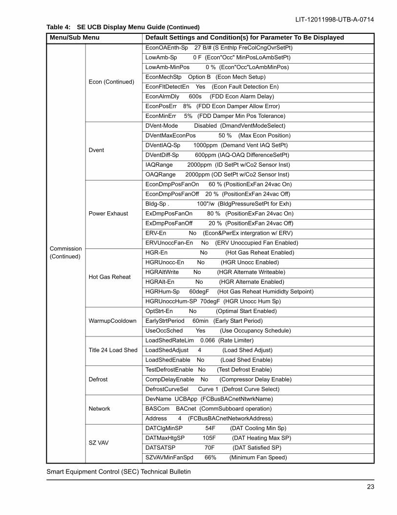
Table 4: SE UCB Display Menu Guide (Continued)
Menu/Sub Menu Default Settings and Condition(s) for Parameter To Be Displayed
Smart Equipment Control (SEC) Technical Bulletin
22
LIT-12011998-UTB-A-0714
Commission(Continued)
Econ (Continued)
EconOAEnth-Sp 27 B/# (S Enthlp FreColCngOvrSetPt)
LowAmb-Sp 0 F (Econ"Occ" MinPosLoAmbSetPt)
LowAmb-MinPos 0 % (Econ"Occ"LoAmbMinPos)
EconMechStp Option B (Econ Mech Setup)
EconFltDetectEn Yes (Econ Fault Detection En)
EconAlrmDly 600s (FDD Econ Alarm Delay)
EconPosErr 8% (FDD Econ Damper Allow Error)
EconMinErr 5% (FDD Damper Min Pos Tolerance)
Dvent
DVent-Mode Disabled (DmandVentModeSelect)
DVentMaxEconPos 50 % (Max Econ Position)
DVentIAQ-Sp 1000ppm (Demand Vent IAQ SetPt)
DVentDiff-Sp 600ppm (IAQ-OAQ DifferenceSetPt)
IAQRange 2000ppm (ID SetPt w/Co2 Sensor Inst)
OAQRange 2000ppm (OD SetPt w/Co2 Sensor Inst)
Power Exhaust
EconDmpPosFanOn 60 % (PositionExFan 24vac On)
EconDmpPosFanOff 20 % (PositionExFan 24vac Off)
Bldg-Sp . 100"/w (BldgPressureSetPt for Exh)
ExDmpPosFanOn 80 % (PositionExFan 24vac On)
ExDmpPosFanOff 20 % (PositionExFan 24vac Off)
ERV-En No (Econ&PwrEx intergration w/ ERV)
ERVUnoccFan-En No (ERV Unoccupied Fan Enabled)
Hot Gas Reheat
HGR-En No (Hot Gas Reheat Enabled)
HGRUnocc-En No (HGR Unocc Enabled)
HGRAltWrite No (HGR Alternate Writeable)
HGRAlt-En No (HGR Alternate Enabled)
HGRHum-Sp 60degF (Hot Gas Reheat Humididty Setpoint)
HGRUnoccHum-SP 70degF (HGR Unocc Hum Sp)
WarmupCooldown
OptStrt-En No (Optimal Start Enabled)
EarlyStrtPeriod 60min (Early Start Period)
UseOccSched Yes (Use Occupancy Schedule)
Title 24 Load Shed
LoadShedRateLim 0.066 (Rate Limiter)
LoadShedAdjust 4 (Load Shed Adjust)
LoadShedEnable No (Load Shed Enable)
Defrost
TestDefrostEnable No (Test Defrost Enable)
CompDelayEnable No (Compressor Delay Enable)
DefrostCurveSel Curve 1 (Defrost Curve Select)
Network
DevName UCBApp (FCBusBACnetNtwrkName)
BASCom BACnet (CommSubboard operation)
Address 4 (FCBusBACnetNetworkAddress)
SZ VAV
DATClgMinSP 54F (DAT Cooling Min Sp)
DATMaxHtgSP 105F (DAT Heating Max SP)
DATSATSP 70F (DAT Satisfied SP)
SZVAVMinFanSpd 66% (Minimum Fan Speed)
Table 4: SE UCB Display Menu Guide (Continued)
Menu/Sub Menu Default Settings and Condition(s) for Parameter To Be Displayed
Smart Equipment Control (SEC) Technical Bulletin
23
LIT-12011998-UTB-A-0714
Controller
FirmFirmVer 3.0.0.1070 (Firmware Revision)
Firm-S Firmware Version (Firmware Status)
Time
TimeZone Central
Time
Date
Network
DevName UCBApp (FC Bus BACnet network name)
BASCom BACnet (Comm Sub-board operation)
Description
Comm-S Waiting For Pol (FC Bus comm status)
FcBusMode Wired (FC Bus Comm Mode)
Address 4 (FC BUS BACnet network address)
OprBaudRate Auto (FC BUS baud rate to be used)
BaudRate Auto (FC BUS baud rate in use)
DeviceId 1 (FC BUS BACnet network Dev ID #)
MiscLanguage English
Units IP (units of measure to be used)
SysCntrls
Misc
Relearn False (clear SA BUS devices in Memory)
#NetSensors 0 (# of NetSensors n SA BUS com)
EconCntlr Not Present (Econ Brd Comm status)
4StgCntlr Not Present (4stg Brd Comm status)
FDDMCntlr Not Present (Refr Circ 1-2 status)
FDDSCntlr Not Present (Refr Circ 3-4 status)
UCB
UCBMainVer 3.0.0.1070 (Firmware Revision)
UCBAppVer 11.2.0.1018 (Software App Rev)
UCBHardVer (Hardware Revision)
Econ
EconMainVer 3.0.0.1070 (Firmware Revision)
EconAppVer 11.2.0.1018 (SoftwareAppRev)
EconHardVer (Hardware Revision)
4Stg
4StgMainVer 3.0.0.1070 (Firmware Revision)
4StgAppVer 11.2.0.1018 (SoftwareAppRev)
4StgHardVer (Hardware Revision)
FDDM
FDDMMainVer 3.0.0.1070 (Firmware Revision)
FDDMAppVer 11.2.0.1018 (SoftwareAppRev)
FDDMHardVer (Hardware Revision)
FDDS
FDDSMainVer 3.0.0.1070 (Firmware Revision)
FDDSAppVer 11.2.0.1018 (SoftwareAppRev)
FDDSHardVer (Hardware Revision)
Update
View Ver 3.0.0.1070 Firmware OK.
LoadFirm No Package Present Error
Backup BKP:Wait bCfg 0%
Restore >serialflash/BackupConfig
Full Clone >serialflash/BackupConfig
Part Clone >serialflash/BackupConfig
Table 4: SE UCB Display Menu Guide (Continued)
Menu/Sub Menu Default Settings and Condition(s) for Parameter To Be Displayed
Smart Equipment Control (SEC) Technical Bulletin
24

LIT-12011998-UTB-A-0714
Update(Continued)
FactryDft Confirm
Dat e Ti me
>Hour 1 (0 through 23)
Minute 1 (0 through 59)
Day 11 (1 through 31)
Month 1 (1 through 12)
Year 2000 (1900 through 2155)
Details
Unit
Unit-S Idle (Unit Status)
Name (Unit Name)
Model# (Unit Model Number)
Serial# (Unit Serial Number)
ModelName (Model Name)
ResetLO (Reset Lockouts)
UnitEn (Unit Enable)
HdwrReset (Hardware Reset)
Setpoints
OprST (Operational Space Temperature)
OprOcc (Operational Occupancy)
RAT 70.4 F (UCB RAT Thermistor input)
OprCVClg-Sp 72 F (CV - Operating Cool Setpoint)
CVOprHtg-Sp 68 F (CV - Operating Heat Setpoint)
ClgOcc-Sp 72 F ( CV - Occ Cooling Setpoint)
ClgUnocc-Sp 80 F (CV - UnOcc Cooling Setpoint)
CVHtgOcc-SP 68 F ( CV - Occ Heating Setpoint)
CVHtgUnocc-Sp 60 F (CV - UnOcc Heating Setpoint)
SAT (60.7 F) (S A Temp Thermistor input)
DctPrs 1.50"/w (VAV UCB Dct Prs 0-5 VDC input)
OprVAVClg-Sp 60 F (VAV Operating Cool Setpoint)
VAVOprHtg-Sp 68F (VAV Operating Heat Setpoint)
DctPrs-Sp 1.50"/w (VAV UCB Dct Prs 0-5 VDC input)
SATUp-Sp 60 F ( VAV - Upper S A Temp Setpoint)
SATLo-Sp 55 F (VAV - Lower S A Temp Setpoint)
SATRst-Sp 72 F (VAV - S A Temp Reset Setpoint)
VAVClgUnocc-Sp 80F (Unocc Cooling Setpoint)
HtgOcc-En Yes (VAV Occ Heating Enable)
VAVHtgOcc-SP 68 F ( VAV - Occ Heating Setpoint)
HtgUnocc-En No (VAV UnOcc Heating Enable)
VAVHtgUnocc-Sp 60 F ( VAV UnOcc Heating Setpt)
Zone Indoor
OprST (Operational Space Temp)
OprOcc (Operational Occupancy)
OprIAQ 477ppm (IAQ 0-10vdcInput in use)
OprSH (Operational Space Humidity)
OprFanReq (Operating Fan Request)
OprSSO (Operational Space Temp SP Offset)
SSO (Space Temp Offset Input)
Table 4: SE UCB Display Menu Guide (Continued)
Menu/Sub Menu Default Settings and Condition(s) for Parameter To Be Displayed
Smart Equipment Control (SEC) Technical Bulletin
25

LIT-12011998-UTB-A-0714
Details(Continued)
Zone (Continued)
Indoor(Continued)
SSORange 3.0 (Space Temp Offset Range)
STSrc (Space Temp Source)
STAlarmOffset 5F (Space Temp Alarm Offset)
STAlarmDelay 3600s (Space Temp Alarm Delay)
OccSrc (Occupancy Source)
TempOccTimeout 7200s (Temporary Occ Timeout)
OccMode External (Occ InitiationMethod)
IAQSrc Local Input (IAQ Input Source)
SH Source Local Input(SpaceHumidInptSource)
FanReqSrc Local Input(ID BlowerInputSource)
SSO Src Local Input (SSO Input Source)
OffDurUnocc Yes (Off During Unoccupied)
UseOccSched Yes (Use Occupancy Schedule)
Outdoor
OprOAT 73.0 F (OutdoorAirTemp in use)
OprOAH 19 %H (OutdoorAirHumidity in use)
OA-Enth 20 B/# (Calculated Enthalpy)
OprOAQ 990ppm (OutdoorAirQuality in use)
OATSrc Local Input (OutdoorAirTemp source)
OAHSrc Local Input (OA Humidity source)
OAQSrc Local Input (OutdoorAirQuality source)
Control Indoor Fan
Status
Fan Off (FAN 24vac output status)
Fan VFD 0% (VFD 2-10vdc output status)
FanCtl-Type Single Speed (UnitOpMode)
APS Off (APS input status)
DctPrs 1.50"/w (DuctPres 0-5vdc input)
SAT 60.7 F (UCB SAT thermistor input)
FanOverload Normal (FanOvrInptStatus)
FanVFDFlt Normal (FLT24vacInptStatus)
Fan-RT .0 hr (Accumulated Fan runtime)
DFS Normal (DFS 24vac input status)
Setup
LowAmbFanPrerunCool 60sec
FanOnDlyCool 0sec (CoolFanOnDelay)
FanOffDlyCool 30sec (CoolFanOffDelay)
FanOnDlyHeat 30sec (HeatFanOnDelay)
FanOffDlyHeat 60sec (HeatFanOffDelay)
FanOn Occ Yes (OccupiedConstantFan)
FanOffStartHeat Yes (FanOff atHeatStart)
Fan Only-% Cmd 50 % (CV IS Fan Only)
1ClgStg-% Cmd 70 % (CV IS 1 Stg Cool)
2ClgStg-% Cmd 80 % (CV IS 2 Stg Cool)
3ClgStg-% Cmd 90 % (CV IS 3 Stg Cool)
4ClgStg-% Cmd 100 % (CV IS 4 Stg Cool)
1HtgStg-% Cmd 100 % (CV IS 1 Stg Heat)
Table 4: SE UCB Display Menu Guide (Continued)
Menu/Sub Menu Default Settings and Condition(s) for Parameter To Be Displayed
Smart Equipment Control (SEC) Technical Bulletin
26
LIT-12011998-UTB-A-0714
Details(Continued)
Control (Continued)
Indoor Fan(Continued)
Setup (Continued)
2HtgStg-% Cmd 100 % (CV IS 2 Stg Heat)
3HtgStg-% Cmd 100 % (CV IS 3 Stg Heat)
DctPrs-Sp 1.50"/w (DuctPres setpoint)
DctShutdownSp 4.50"/w (DuctPressLimit)
Clg
Status
Clg-S Off-Idle (Cooling Status)
#ClgStgs 2 (# of cooling stages)
SAT 60.7 F (SAT thermistor input)
StgClgCmd 0% (Staged Cooling Command)
Stage 1
C1-S Off - Idle (Compressor Stage Status)
C1 Off (C1 24vacOutputStatus)
C1-En Yes (C1 24vacOutputEnabled)
C1OnTmr 0 min (C1MinRuntimeRemain)
C1ASCDTmr 0 min (C1 ASC TimeRemain)
C1RunTim . 0 hr(C1 outptAccumRuntime)
EC1 42 F (EC1 thermistor input)
CC1 96 F (CC1 thermistor input)
SLP-1 (Suction Pressure 1)
LLP-1 (Liquid Pressure 1)
SLT-1 (Suction Temperature 1)
LLT-1 (Liquid Temperature 1)
C1-EI (Efficiency Index 1)
C1-CI (Capacity Index 1)
C1-CondTempOvrAmb (Condensing Temp over Ambient 1)
C1-EvapTempValue (Evap Temp Value Circuit 1)
Stage 2
C2-S Off - Idle (Compressor Stage Status)
C2 Off (C2 24vacOutputStatus)
C2-En Yes (C2 24vacOutputEnabled)
C2OnTmr 0 min (C2MinRuntimeRemain)
C2ASCDTmr 0 min (C2 ASC TimeRemain)
C2RunTim . 0 hr(C2 outptAccumRuntime)
EC2 42 F (EC2 thermistor input)
CC2 96 F (CC2 thermistor input)
SLP-2 (Suction Pressure 2)
LLP-2 (Liquid Pressure 2)
SLT-2 (Suction Temperature 2)
LLT-2 (Liquid Temperature 2)
C2-EI (Efficiency Index 2)
C2-CI (Capacity Index 2)
C2-CondTempOvrAmb (Condensing Temp over Ambient 2)
C2-EvapTempValue (Evap Temp Value Circuit 2)
Stage 3C3-S Off - Idle (Compressor Stage Status)
C3 Off (C3 24vacOutputStatus)
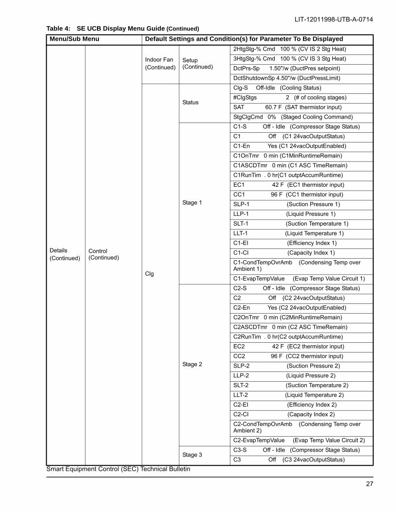
Table 4: SE UCB Display Menu Guide (Continued)
Menu/Sub Menu Default Settings and Condition(s) for Parameter To Be Displayed
Smart Equipment Control (SEC) Technical Bulletin
27

LIT-12011998-UTB-A-0714
Details(Continued)
Control (Continued)
Clg (Continued)
Stage 3 (Continued)
C3-En Yes (C3 24vacOutputEnabled)
C3OnTmr 0 min (C3MinRuntimeRemain)
C3ASCDTmr 0 min (C3 ASC TimeRemain)
C3RunTim . 0 hr(C3 outptAccumRuntime)
EC3 42 F (EC3 thermistor input)
CC3 96 F (CC3 thermistor input)
SLP-3 (Suction Pressure 3)
LLP-3 (Liquid Pressure 3)
SLT-3 (Suction Temperature 3)
LLT-3 (Liquid Temperature 3)
C3-EI (Efficiency Index 3)
C3-CI (Capacity Index 3)
C3-CondTempOvrAmb (Condensing Temp over Ambient 3)
C3-EvapTempValue (Evap Temp Value Circuit 3)
Stage 4
C4-S Off - Idle (Compressor Stage Status)
C4 Off (C4 24vacOutputStatus)
C4-En Yes (C4 24vacOutputEnabled)
C4OnTmr 0 min (C4MinRuntimeRemain)
C4ASCDTmr 0 min (C4 ASC TimeRemain)
C4RunTim . 0 hr(C4 outptAccumRuntime)
EC4 42 F (EC4 thermistor input)
CC4 96 F (CC4 thermistor input)
SLP-4 (Suction Pressure 4)
LLP-4 (Liquid Pressure 4)
SLT-4 (Suction Temperature 4)
LLT-4 (Liquid Temperature 4)
C4-EI (Efficiency Index 4)
C4-CI (Capacity Index 4)
C4-CondTempOvrAmb (Condensing Temp over Ambient 4)
C4-EvapTempValue (Evap Temp Value Circuit 4)
Setup
Clg-En Yes ( Cooling Enabled/Disabled)
MinRtCoolStg 3min (MinCompRunTime)
LeadLag-En No ( EqualCompRuntime)
LowAmbFanPrerunCool 60 sec
ClgOATCutout-En Yes (LowAmbComp LO)
ClgOATCutout 45 F (LoAmbCompLO StPt)
ClgAdapTunEn Yes (Cooling Auto Tune Enable)
SATCoolLimit-En Yes (Enable SAT Limit)
SATCoolLimit-Sp 50 F (SAT Limit SetPt)
EconLoad-En No (EconLoadingEnabled)
AllCompOff-Econ No (SuplmntEconoEnable)
LowAmb-En No (Low Ambient Enabled)
Table 4: SE UCB Display Menu Guide (Continued)
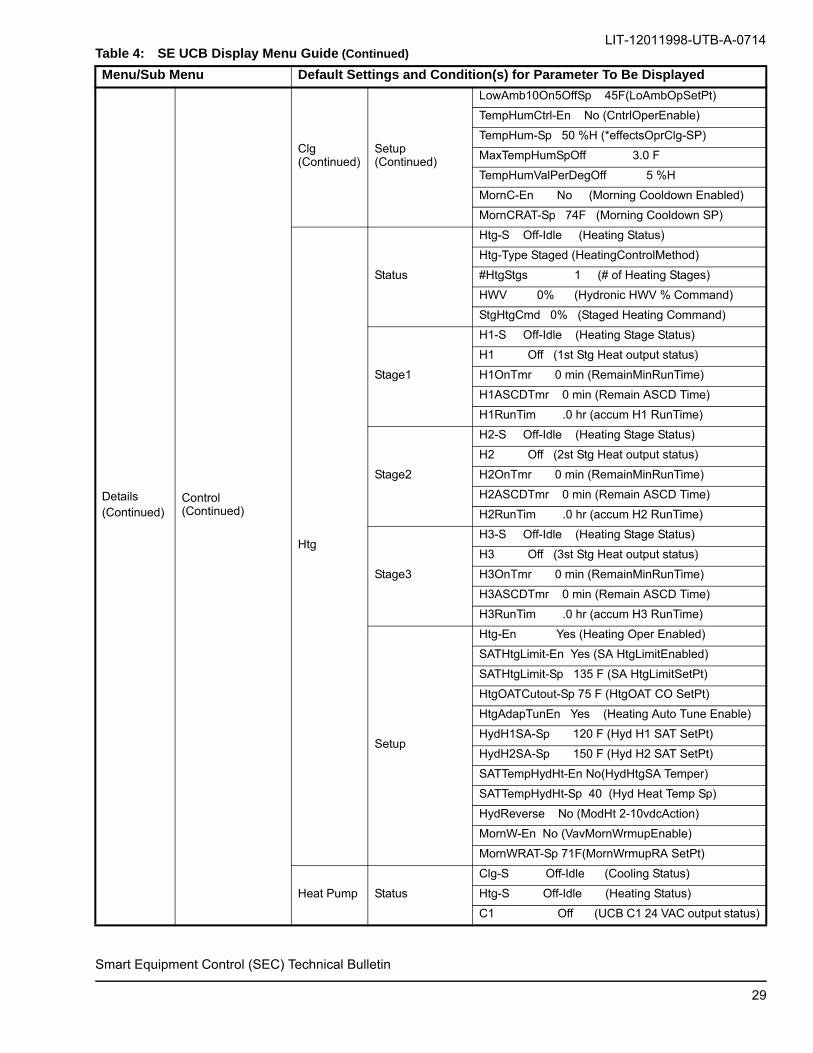
Menu/Sub Menu Default Settings and Condition(s) for Parameter To Be Displayed
Smart Equipment Control (SEC) Technical Bulletin
28
LIT-12011998-UTB-A-0714
Details(Continued)
Control (Continued)
Clg (Continued)
Setup (Continued)
LowAmb10On5OffSp 45F(LoAmbOpSetPt)
TempHumCtrl-En No (CntrlOperEnable)
TempHum-Sp 50 %H (*effectsOprClg-SP)
MaxTempHumSpOff 3.0 F
TempHumValPerDegOff 5 %H
MornC-En No (Morning Cooldown Enabled)
MornCRAT-Sp 74F (Morning Cooldown SP)
Htg
Status
Htg-S Off-Idle (Heating Status)
Htg-Type Staged (HeatingControlMethod)
#HtgStgs 1 (# of Heating Stages)
HWV 0% (Hydronic HWV % Command)
StgHtgCmd 0% (Staged Heating Command)
Stage1
H1-S Off-Idle (Heating Stage Status)
H1 Off (1st Stg Heat output status)
H1OnTmr 0 min (RemainMinRunTime)
H1ASCDTmr 0 min (Remain ASCD Time)
H1RunTim .0 hr (accum H1 RunTime)
Stage2
H2-S Off-Idle (Heating Stage Status)
H2 Off (2st Stg Heat output status)
H2OnTmr 0 min (RemainMinRunTime)
H2ASCDTmr 0 min (Remain ASCD Time)
H2RunTim .0 hr (accum H2 RunTime)
Stage3
H3-S Off-Idle (Heating Stage Status)
H3 Off (3st Stg Heat output status)
H3OnTmr 0 min (RemainMinRunTime)
H3ASCDTmr 0 min (Remain ASCD Time)
H3RunTim .0 hr (accum H3 RunTime)
Setup
Htg-En Yes (Heating Oper Enabled)
SATHtgLimit-En Yes (SA HtgLimitEnabled)
SATHtgLimit-Sp 135 F (SA HtgLimitSetPt)
HtgOATCutout-Sp 75 F (HtgOAT CO SetPt)
HtgAdapTunEn Yes (Heating Auto Tune Enable)
HydH1SA-Sp 120 F (Hyd H1 SAT SetPt)
HydH2SA-Sp 150 F (Hyd H2 SAT SetPt)
SATTempHydHt-En No(HydHtgSA Temper)
SATTempHydHt-Sp 40 (Hyd Heat Temp Sp)
HydReverse No (ModHt 2-10vdcAction)
MornW-En No (VavMornWrmupEnable)
MornWRAT-Sp 71F(MornWrmupRA SetPt)
Heat Pump Status
Clg-S Off-Idle (Cooling Status)
Htg-S Off-Idle (Heating Status)
C1 Off (UCB C1 24 VAC output status)
Table 4: SE UCB Display Menu Guide (Continued)
Menu/Sub Menu Default Settings and Condition(s) for Parameter To Be Displayed
Smart Equipment Control (SEC) Technical Bulletin
29

LIT-12011998-UTB-A-0714
Details(Continued)
Control (Continued)
Heat Pump(Continued)
Status(Continued)
C2 Off (UCB C2 24 VAC output status)
RevVlv Off (Reversing Valve)
AuxHtg Off (Auxiliary Heat)
Mode Cooling (Mode)
Stage 1
C1-S Off - Idle (Compressor Stage Status)
C1 Off (C1 24vacOutputStatus)
C1-En Yes (C1 24vacOutputEnabled)
C1OnTmr 0 min (C1MinRuntimeRemain)
C1ASCDTmr 0 min (C1 ASC TimeRemain)
C1RunTim . 0 hr(C1 outptAccumRuntime)
EC1 42 F (EC1 thermistor input)
CC1 96 F (CC1 thermistor input)
SLP-1 (Suction Pressure 1)
LLP-1 (Liquid Pressure 1)
SLT-1 (Suction Temperature 1)
LLT-1 (Liquid Temperature 1)
C1-EI (Efficiency Index 1)
C1-CI (Capacity Index 1)
C1-CondTempOvrAmb (Condensing Temp over Ambient 1)
C1-EvapTempValue (Evap Temp Value Circuit 1)
Stage 2
C2-S Off - Idle (Compressor Stage Status)
C2 Off (C2 24vacOutputStatus)
C2-En Yes (C2 24vacOutputEnabled)
C2OnTmr 0 min (C2MinRuntimeRemain)
C2ASCDTmr 0 min (C2 ASC TimeRemain)
C2RunTim . 0 hr(C2 outptAccumRuntime)
EC2 42 F (EC2 thermistor input)
CC2 96 F (CC2 thermistor input)
SLP-2 (Suction Pressure 2)
LLP-2 (Liquid Pressure 2)
SLT-2 (Suction Temperature 2)
LLT-2 (Liquid Temperature 2)
C2-EI (Efficiency Index 2)
C2-CI (Capacity Index 2)
C2-CondTempOvrAmb (Condensing Temp over Ambient 2)
C2-EvapTempValue (Evap Temp Value Circuit 2)
Setup
Clg-En Yes ( Cooling Enabled/Disabled)
Htg-En Yes (Heating Oper Enabled)
MinRtCoolStg 3min (MinCompRunTime)
LeadLag-En No ( EqualCompRuntime)
LowAmbFanPrerunCool 60 sec
ClgOATCutout-En Yes (LowAmbComp LO)
Table 4: SE UCB Display Menu Guide (Continued)
Menu/Sub Menu Default Settings and Condition(s) for Parameter To Be Displayed
Smart Equipment Control (SEC) Technical Bulletin
30

LIT-12011998-UTB-A-0714
Details(Continued)
Control (Continued)
Heat Pump(Continued)
Setup (Continued)
ClgOATCutout 45 F (LoAmbCompLO StPt)
SATCoolLimit-En Yes (Enable SAT Limit)
SATCoolLimit-Sp 50 F (SAT Limit SetPt)
SATHtgLimit-En Yes (SA HtgLimitEnabled)
SATHtgLimit-Sp 135 F (SA HtgLimitSetPt)
ClgAdapTunEn Yes (Cooling Auto Tune Enable)
HtgAdapTunEn Yes (Heating Auto Tune Enable)
EconLoad-En No (EconLoadingEnabled)
AllCompOff-Econ No (SuplmntEconoEnable)
LowAmb-En No (Low Ambient Enabled)
LowAmb10On5OffSp 45F(LoAmbOpSetPt)
TempHumCtrl-En No (CntrlOperEnable)
TempHum-Sp 50 %H (*effectsOprClg-SP)
MaxTempHumSpOff 3.0 F
TempHumValPerDegOff 5 %H
Econ
Status
Econ 0 % (ECON 2-10vdc output status)
Econ-Free No (FreeCooling available)
FreeClg-Mode Dry Bulb (ChngoverMode)
MAT 71 F (MAT thermistor input)
OA-Enth 20 B/# (CalcOA enthalpyInput)
OprOAH 19 %H (OA Humidity in use)
Opr OAT 73.0 F (OA Temp in use)
RA-Enth 20B/# (RA enthalpy input)
RAH 19.4 %H (RA Humidity0-10vdcInput)
RAT 70.4 F (UCB RAT thermistorInput)
SAH 71 %H (SA Humidity 0-10vdcInput)
Setup
Econ-En Yes (EconoFreeCoolingEnable)
FreeClg-Sel Auto(FreClgChngOvrMethod)
Econ-MinPos 20 % (OccEconoMinPos)
EconOAT-SpEn 55 F (DryBlbChgOvrSetPt)
EconOAEnth-Sp 27 B/# (EnthCngOvrSetPt)
LowAmb-Sp 0 F (LoAmbMinPossSetPt)
LowAmb-MinPos 0%v(OccLoAmbMinPos)
IAQEcon-MaxPos 50%(DVentMaxEconPos)
LowSpeedFan-MinPos 25%(OccLoFanPos)
EconMechStp Option B (Econ Mech Setup)
Power Exhaust
Status
ExFan Off (EX-FAN 24vacOutputStatus)
ExFanVFD 0 % (EX VFD2-10vdc Output)
ExFanVFDFlt Normal (VFD FLT24vacInput)
ExFan-RT .0 hr(24vacOutputAccRunTime)
EAD-O 0 % (EXVFD2-10vdcOutptStatus)
BldgPres .164"/w(BldgPress0-5vdcInput)
Bldg-Sp 100"/w(ExDmprBldgPresSetPt)
Table 4: SE UCB Display Menu Guide (Continued)
Menu/Sub Menu Default Settings and Condition(s) for Parameter To Be Displayed
Smart Equipment Control (SEC) Technical Bulletin
31

LIT-12011998-UTB-A-0714
Details(Continued)
Control (Continued)
Power Exhaust (Continued)
Setup
ExFType None(PwrExFanModeSelection)
EconDmpPosFanOn 60 % (FanOnPosition)
EconDmpPosFanOff 20 % (FanOffPosition)
ExDmpPosFanOn 80 % (FanOnPosition)
ExDmpPosFanOff 20 % (FanOffPosition)
ERV-En No(Econ&PwrExIntrgrationW/ERV)
ERVUnoccFan-En No (ERV Unocc Fan Enabled)
Demand Vent
DVent-Mode Disabled (DemandVentiMode)
OprIAQ 477ppm (IAQ 0-10vdcInput in use)
DVentMaxEconPos 50 % (IAQ Econ-MaxPos)
DVentIAQ-Sp 1000ppm (OccIAQEconOperSetPt)
DVentDiff-Sp 600ppm(Occ Diff IAQ/OAQ SetPt)
IAQRange 2000ppm (ppm@10vdcIAQ Output)
OAQRange 2000ppm (ppm@10vdcOAQ Output)
AirMon Station
MOAFlow-Sp10CFM(OcMinOAflowSetPt)
Fr Air 7129CFM (FR AIR 0-10vdc Input)
MOA-Range 10000CFM(Cfm/10vdcOutpt)
Hot Gas Reheat
HGR-S Off-Idle (HGR Status)
HGR Off Hot Gas Reheat
HGR-En No (Hot Gas Reheat Enabled)
HGRUnocc-En No (HGR Unocc Enabled)
HGRAltWrite No (HGR Alternate Writeable)
HGRAlt-En No (HGR Alternate Enabled)
HGRHum-Sp 60degF (Hot Gas Reheat Humididty Setpoint)
HGRUnoccHum-SP 70degF (HGR Unocc Hum Sp)
Smoke Ctrl
OprPurgeCmd False (ActivePurgeCmd)
PurgeCmdSrc RATemp(PurgeCmdSource)
Purge False (Purge Input status)
NetPurge ?Unrel (PurgeCommandStatus)
SD Normal ( SD 24 VAC input status)
Service Inputs Sensors
ST 60.5 F (UCB ST ThermistorInput)
SSO .0 F (UCB SSO 0-20,000 Ω input)
IAQ 477ppm (IAQ 0-10 VDC Input)
RAH 49.6 %H ( UCB RAH 0-10vdcInput)
OAT 73.0 F (UCB OAT ThermistorInput)
OAH 49.6 %H (OAH 0-10vdc Input)
OAQ 477ppm (OAQ 0-10vdc Input)
SAT 60.7 F (UCB SAT ThermistorInput)
RAT 73.0 F (UCB RAT ThermistorInput)
SAH 49 %H (SAH 0-10 vdcInput)
DctPrs 1.50"/w(DCT PRS 0-5vdcInput )
BldgPres .164"/w (BldgPres 0-5vdc Input)
MAT 71 F (MAT thermistor input)
Table 4: SE UCB Display Menu Guide (Continued)
Menu/Sub Menu Default Settings and Condition(s) for Parameter To Be Displayed
Smart Equipment Control (SEC) Technical Bulletin
32

LIT-12011998-UTB-A-0714
Details(Continued)
Service (Continued)
Inputs (Continued)
Sensors (Continued)
Fr Air 7129CFM (FR AIR 0-10vdc Input)
UCB24VForOutputs 24
EconDampPos ( AI-IN 0-10vdc Input)
Coil Sensors
EC1 42 F (EC1 Thermistor Input)
CC1 96 F (CC1 Thermistor Input)
EC2 41 F (EC2 Thermistor Input)
CC2 117 F (CC2 Thermistor Input)
EC3 42 F (EC3 Thermistor Input)
CC3 96 F (CC3 Thermistor Input)
EC4 41 F (EC4 Thermistor Input)
CC4 117 F (CC4 Thermistor Input)
Thermostat
Y1-Tstat Off (24vac input to Y1 term)
Y2-Tstat Off (24vac input to Y2 term)
Y3-Tstat Off (24vac input to Y3 term)
Y4-Tstat Off (24vac input to Y4 term)
W1-Tstat Off (24vac input to W1 term)
W2-Tstat Off (24vac input to W2 term)
W3-Tstat Off (24vac input to W3 term)
G-Tstat Off (24vac input to G term)
Tstat-Only Yes (T-Stat Input Only)
Binary Inputs
Limit Normal (Limit 24vac input status)
Lim2 Normal (Limit 24vac input status)
Lim3 Normal (Limit 24vac input status)
MV No (MV pin 24vac input status)
GV2 No (GV2 pin 24vac input status)
GV3 No (GV3,4 pin 24vac input status)
HPS1 Normal (HPS1 24vac input status)
LPS1 Normal (LPS1 24vac input status)
FS1 Normal (Freeze Protect1 status)
HPS2 Normal (HPS2 24vac input status)
LPS2 Normal (LPS2 24vac input status)
FS2 Normal (Freeze Protect2 status)
HPS3 Normal (HPS3 34vac input status)
LPS3 Normal (LPS3 34vac input status)
FS3 Normal (Freeze Protect3 status)
HPS4 Normal (HPS4 44vac input status)
LPS4 Normal (LPS4 44vac input status)
FS4 Normal (Freeze Protect4 status)
FanOvrload Normal(24VAC input status)
APS Off (AirProving Switch input status)
DFS Normal (DrtyFltr Switch input status)
SD Normal (Smoke Detect input status)
Purge False (Purge 24vac input status)
Table 4: SE UCB Display Menu Guide (Continued)
Menu/Sub Menu Default Settings and Condition(s) for Parameter To Be Displayed
Smart Equipment Control (SEC) Technical Bulletin
33

LIT-12011998-UTB-A-0714
Details(Continued)
Service (Continued)
Inputs (Continued)
Binary Inputs (Continued)
ExFanVFDFlt Normal (24vac input status)
FanVFDFlt Normal (24vac input status)
OCC Unoccupied ( 24vac input status)
TempOcc (Temporary Occupancy)
Safeties
HPS1-LO Normal (HiPress1 switch status)
LPS1-LO Normal(LoPress1 switch status)
FS1-LO Normal (Freeze Protect1 status)
HPS2-LO Normal (HiPress2 switch status)
LPS2-LO Normal (LoPress2 switch status)
FS2-LO Normal (Freeze Protect2 status)
HPS3-LO Normal (HiPress3 switch status)
LPS3-LO Normal (LoPress3 switch status)
FS3-LO Normal (Freeze Protect3 status)
HPS4-LO Normal (HiPress4 switch status)
LPS4-LO Normal (LoPress4 switch status)
FS4-LO Normal (Freeze Protect4 status)
LimitLO Normal (HeaT Limit status)
Lim2LO Normal (HeaT Limit status)
Lim3LO Normal (HeaT Limit status)
Network Inputs
NetST ?Unrel (FC Bus Space Temp)
NetSSO ?Unrel (FC BusSpaceSetPtOffset)
NetSH ?Unrel (FC BusSpaceHumidity)
NetOcc Not Set (FC BusOccupncyStatus)
NetTempOcc False(TempOccCommand)
NetIAQ ?Unrel (FC Bus IAQ value)
NetFanReq ?Unrel (FC BusFanOn reqst)
NetOAT ?Unrel (FC Bus OA Temp)
NetOAH ?Unrel (FC Bus OA Humidity)
NetOAQ ?Unrel (FC Bus OA Quality)
NetPurge ?Unrel (FC BusPurge Comand)
DirLoadshd (Direct Loadshed)
Redline (Redline)
LoadShedEnable (Load Shed Enable)
LoadShedRateLim (Load Shed Rate Limit)
LoadShedAdjust (Load Shed Adjust)
Outputs Relay
C1 Off (1st Cool 24 VAC output)
C2 Off (2nd+ Cool 24 VAC output)
C3 Off (3rd+ Cool 24 VAC output)
C4 Off (4th+ Cool 24 VAC output)
H1 Off (1st Heat 24 VAC output)
H2 Off (2nd+ Heat 24 VAC output)
H3 Off (3rd+ Heat 24 VAC output)
ExFan Off (EX-Fan 24 VAC output)
Table 4: SE UCB Display Menu Guide (Continued)
Menu/Sub Menu Default Settings and Condition(s) for Parameter To Be Displayed
Smart Equipment Control (SEC) Technical Bulletin
34

LIT-12011998-UTB-A-0714
Details(Continued)
Service (Continued)
Outputs (Continued)
Relay (Continued)
CN-Fan Off (CN-Fan 24 VAC output)
CF2 Off (CF2 24 VAC output)
Fan Off (Fan 24 VAC output)
VAV Box Off (VAV Box)
HGR Off (HGR Command)
X-Out Off (X term 24 VAC output)
Analog
FanVFD 0 % ( VFD 2-10 VDC output)
Econ 0 % ( Econ 2-10 VDC output)
ExFanVFD 0 % (ExFan 2-10 VDC output)
HWV 0 % ( HWV VDC output)
Factory
Standard
#ClgStgs 2 (# of Cooling Stages)
#HtgStgs 0 (# of Heating Stages)
#HtPumpStgs 0 (# of Heat Pumps)
#RefrigSys 0 (#Refrig Circuits)
Htg-Type Staged (Heating Control Method)
FanCtl-Type Single Speed (I D Blower Type)
APSSetup None (Air Proving Switch Operation)
HGR-En No (HGR Enabled)
HGP-Inst No (Hot Gas Bypass Installed)
BASCom BACnet (Comm sub-board present)
Freeze-Sp 26.0 F (Evap freeze protect setpt)
DFSINst (Dirty Filter Switch Installed)
FanOffDlyCool (Fan Off Delay for Cool)
FanOnDlyCool 0sec (CoolFanOnDelay)
FanOffDlyHeat 60sec (HeatFanOffDelay)
FanOnDlyHeat 30sec (HeatFanOnDelay)
LowAmb-En No (Low Ambient Enabled)
LowAmbFanPrerunCool (Low Ambient Fan Prerun Time)
LowAmb10On5OffSp 45F(LoAmbOpSetPt)
LeadLag-En No ( EqualCompRuntime)
Tstat-Only Yes (T-Stat Input Only)
ClgOATCutout 45 F (LoAmbCompLO StPt)
FDD
UnitType
EER
SubcoolGoal
RefrigType
HiSidePortLoc
EvapCoil-Type
CondCoil-Type
InMeterDev-Type
OutMeterDev-Type
UnitCap
Table 4: SE UCB Display Menu Guide (Continued)
Menu/Sub Menu Default Settings and Condition(s) for Parameter To Be Displayed
Smart Equipment Control (SEC) Technical Bulletin
35

LIT-12011998-UTB-A-0714
Details(Continued)
Service (Continued)
Factory (Continued)
FDD
FanPower
SuperHeatGoal
Altitude
Economizer
Econ-MinPos 20 % (OccEconoMinPos)
LowSpeedFan-MinPos 25%(OccLoFanPos)
ExFType None (ExHaust Fan Mode/Type)
Misc
SZVAVEn No (Single Zone VAV Enabled)
CntrlType CV (Rooftop Controller Type)
EquipType RTU (Rooftop Equipment Type)
PumpOut-En Disabled (Pump Out Enabled)
Self Test
Start (Begins the Self Test Sequence)
Pause (Causes the sequence to hold any outputs ON for 10 minutes. This excludes safety trips)
TestStatus (Displays current state of the Self Test Sequencer)
Reset (Erases the previous Self Test results and prepares the Self Test Sequencer for another test run)
Cancel (Stops the Self Test Sequencer and returns the SEC to normal operation)
View Results
FanResult Pass-Fail (APS On Early or APS Off)
C1Result Pass-Fail-Warning
C2Result Pass-Fail-Warning
C3Result Pass-Fail-Warning
C4Result Pass-Fail-Warning
H1Result Pass-Fail-Warning
H2Result Pass-Fail-Warning
H3Result Pass-Fail-Warning
EconResult Pass-Fail (Damper)
ExhResult Warning-Pass (BSP not dropped)
Table 5: SE RTU BACnet Modbus
Property Description Property
BACNET POINT INFO
MODBUS POINT INFO
BACOidModbus RegisterAddress
ModbusScaleFactor
Modbus Boolean
Flag
Modbus Signed
Flag
Modbus Offset
Modbus WriteableFlag
Unit Status Unit-S 29803 280 #N/A 0 #N/A 0 0
Name Name 29804 #N/A #N/A #N/A #N/A #N/A #N/A
Model No. Model# 29805 #N/A #N/A #N/A #N/A #N/A #N/A
Serial No. Serial# 29806 #N/A #N/A #N/A #N/A #N/A #N/A
Firmware Version FirmVer 29807 #N/A #N/A #N/A #N/A #N/A #N/A
Exhaust Fan Type ExFType 29503 #N/A #N/A #N/A #N/A #N/A #N/A
Reset Lockouts ResetLO 29826 80 #N/A 0 #N/A 0 1
Single Zone VAV Enable SZVAVEn 29908 #N/A #N/A #N/A #N/A #N/A #N/A
Table 4: SE UCB Display Menu Guide (Continued)
Menu/Sub Menu Default Settings and Condition(s) for Parameter To Be Displayed
Smart Equipment Control (SEC) Technical Bulletin
36

LIT-12011998-UTB-A-0714
Smart Equipment Control (SEC) Technical Bulletin
Hardware Reset HdwrReset 29909 126 #N/A 0 #N/A 0 1
Y1 - Thermostat Y1-Tstat 29504 281 #N/A 0 #N/A 0 0
Y2 - Thermostat Y2-Tstat 29505 282 #N/A 0 #N/A 0 0
Y3 - Thermostat Y3-Tstat 29506 283 #N/A 0 #N/A 0 0
Y4 - Thermostat Y4-Tstat 29507 284 #N/A 0 #N/A 0 0
W1 - Thermostat W1-Tstat 29508 285 #N/A 0 #N/A 0 0
W2 - Thermostat W2-Tstat 29509 286 #N/A 0 #N/A 0 0
W3 - Thermostat W3-Tstat 29510 287 #N/A 0 #N/A 0 0
G - Thermostat G-Tstat 29511 288 #N/A 0 #N/A 0 0
X-OUT X-Out 29513 289 #N/A 0 #N/A 0 0
Thermostat Only Control Tstat-Only 29514 #N/A #N/A #N/A #N/A #N/A #N/A
Fan Status Fan-S 29550 302 #N/A 0 #N/A 0 0
Supply Fan Pct Output FanVFD 29551 157 X10 0 Signed 0 0
Fan VFD Fault FanVFDFlt 29552 303 #N/A 0 #N/A 0 0
Supply Fan Overload FanOvrload 29553 304 #N/A 0 #N/A 0 0
Fan Accumulated Runtime
Fan-RT 29554 9 X10 0 Unsigned 0 1
Fan Control Type FanCtl-Type 29555 #N/A #N/A #N/A #N/A #N/A #N/A
Air Proving Switch Setup APSSetup 29556 #N/A #N/A #N/A #N/A #N/A #N/A
Air Proving Switch APS 29557 305 #N/A 0 #N/A 0 0
Fan On Delay for Cool FanOnDlyCool 29558 90 #N/A 0 #N/A 0 1
Fan Off Delay for Cool FanOffDlyCool 29559 #N/A #N/A #N/A #N/A #N/A #N/A
Fan On Delay for Heat FanOnDlyHeat 29560 #N/A #N/A #N/A #N/A #N/A #N/A
Fan Off Delay for Heat FanOffDlyHeat 29561 #N/A #N/A #N/A #N/A #N/A #N/A
Dirty Filter Switch DFS 29562 306 #N/A 0 #N/A 0 0
Fan Command Fan 29563 307 #N/A 0 #N/A 0 0
Supply Air Temperature SAT 29564 158 X10 0 Signed 0 0
Duct Static Pressure DctPrs 29565 159 X100 0 Signed 0 0
Duct Pressure Setpoint DctPrs-Sp 29566 10 X100 0 Signed 0 1
Duct Pressure Shutdwn Sp
DctShutdownSp 29567 11 X100 0 Signed 0 1
Cont SF Oper in Occ Mode FanOnOcc 29568 91 #N/A 0 #N/A 0 1
Trn Off Cnt Fn Opr St HtFanOffStartHeat 29569 92 #N/A 0 #N/A 0 1
Occ No Heat or Cl Pct Sp FanOnly-%Cmd
29570 12 X10 0 Signed 0 1
Occ 1 Stage of Cl Pct Sp 1ClgStg-%Cmd 29571 13 X10 0 Signed 0 1
Table 5: SE RTU BACnet Modbus (Continued)
Property Description Property
BACNET POINT INFO
MODBUS POINT INFO
BACOidModbus RegisterAddress
ModbusScaleFactor
Modbus Boolean
Flag
Modbus Signed
Flag
Modbus Offset
Modbus WriteableFlag
37

LIT-12011998-UTB-A-0714
Smart Equipment Control (SEC) Technical Bulletin
Occ 2 Stges of Cl Pct Sp 2ClgStg-%Cmd
29572 14 X10 0 Signed 0 1
Occ 1 Stage of Ht Pct Sp 1HtgStg-%Cmd 29573 17 X10 0 Signed 0 1
Occ 2 Stges of Ht Pct Sp2HtgStg-%Cmd 29574 18 X10 0 Signed 0 1
Occ 3 Stges of Cl Pct Sp 3ClgStg-%Cmd
29819 15 X10 0 Signed 0 1
Occ 4 Stges of Cl Pct Sp 4ClgStg-%Cmd 29820 16 X10 0 Signed 0 1
Occ 3 Stges of Ht Pct Sp3HtgStg-%Cmd 29821 19 X10 0 Signed 0 1
SZ VAV Minimum Fan Speed
SZVAVMinFanSpd
29913 73 X10 0 Signed 0 1
Clg Mode Ena For Oper Clg-En 29575 93 #N/A 0 #N/A 0 1
Number of Cooling Stages #ClgStgs 29576 #N/A #N/A #N/A #N/A #N/A #N/A
Cooling Status Clg-S 29577 308 #N/A 0 #N/A 0 0
Min Runtime Clg Stage MinRtCoolStg 29578 20 X10 0 Unsigned 0 1
Compressor Lead-Lag Enable LeadLag-En 29579 #N/A #N/A #N/A #N/A #N/A #N/A
Low Ambient Fan Pre-run Time For Cooling
LowAmbFanPrerunCool 29580 #N/A #N/A #N/A #N/A #N/A #N/A
OAT Cooling Cutout Ena ClgOATCutout-En
29581 94 #N/A 0 #N/A 0 1
OAT Cooling Cutout ClgOATCutout 29582 21 X10 0 Signed 0 1
Economizer Loading Ena EconLoad-En 29583 95 #N/A 0 #N/A 0 1
All Stgs Clg Off in Econ AllCompOff-Econ 29584 96 #N/A 0 #N/A 0 1
Low Ambient Cooling Stages 10 on 5 off Setpoint
LowAmb10On5OffSp 29585 #N/A #N/A #N/A #N/A #N/A #N/A
Temp/Hum (Ret) Cntrl Ena
TempHumCtrl-En 29586 97 #N/A 0 #N/A 0 1
Temp/Humidity Sp TempHum-Sp 29587 22 X10 0 Signed 0 1
Max Temp / Hum Sp Offset
MaxTempHumSpOff 29588 23 X10 0 Signed 0 1
Temp-Hum Value-Deg Offst
TempHumValPerDegOff 29589 24 X10 0 Signed 0 1
SAT Limit for Clg Ena SATCoolLimit-En
29590 98 #N/A 0 #N/A 0 1
SAT Limit for Cooling Sp SATCoolLimit-Sp 29591 25 X10 0 Signed 0 1
Freeze Condition Setpoint Freeze-Sp 29592 #N/A #N/A #N/A #N/A #N/A #N/A
Table 5: SE RTU BACnet Modbus (Continued)
Property Description Property
BACNET POINT INFO
MODBUS POINT INFO
BACOidModbus RegisterAddress
ModbusScaleFactor
Modbus Boolean
Flag
Modbus Signed
Flag
Modbus Offset
Modbus WriteableFlag
38

LIT-12011998-UTB-A-0714
Smart Equipment Control (SEC) Technical Bulletin
Condenser Fan 1 CN-Fan 29593 309 #N/A 0 #N/A 0 0
Condenser Fan 2 CF2 29594 310 #N/A 0 #N/A 0 0
Unit Type UnitType 29595 #N/A #N/A #N/A #N/A #N/A #N/A
EER EER 29596 #N/A #N/A #N/A #N/A #N/A #N/A
Subcooling Goal SubcoolGoal 29597 #N/A #N/A #N/A #N/A #N/A #N/A
Refrigerant Type RefrigType 29598 #N/A #N/A #N/A #N/A #N/A #N/A
High Side Port Location HiSidePortLoc 29599 #N/A #N/A #N/A #N/A #N/A #N/A
Evaporator Coil Type EvapCoil-Type 29600 #N/A #N/A #N/A #N/A #N/A #N/A
Condenser Coil Type CondCoil-Type 29601 #N/A #N/A #N/A #N/A #N/A #N/A
Indoor Metering Device Type
InMeterDev-Type
29602 #N/A #N/A #N/A #N/A #N/A #N/A
Outdoor Metering Device Type
OutMeterDev-Type 29603 #N/A #N/A #N/A #N/A #N/A #N/A
VAV Clg SA Temp Upper Sp SATUp-Sp 29604 26 X10 0 Signed 0 1
VAV Cig SA Temp Lower Sp
SATLo-Sp 29605 27 X10 0 Signed 0 1
VAV SA Temp Reset Sp SATRst-Sp 29606 28 X10 0 Signed 0 1
VAV Oper Clg SA Temp Sp OprVAVClg-Sp 29607 160 X10 0 Signed 0 0
CV Occupied Cooling Sp ClgOcc-Sp 29608 29 X10 0 Signed 0 1
CV Unoccupied Cooling Sp ClgUnocc-Sp 29609 30 X10 0 Signed 0 1
CV Operating Cooling Sp OprCVClg-Sp 29610 161 X10 0 Signed 0 0
Unit Capacity UnitCap 29886 #N/A #N/A #N/A #N/A #N/A #N/A
Fan Power FanPower 29887 #N/A #N/A #N/A #N/A #N/A #N/A
Super Heat Goal SuperHeatGoal
29888 #N/A #N/A #N/A #N/A #N/A #N/A
Altitude Altitude 29889 31 X10 0 Signed 0 1
Cooling Adaptive Tuning Enable ClgAdapTunEn 29882 100 #N/A #N/A #N/A #N/A 1
Refrig Systems Installed #RefrigSys 29890 32 X10 0 Unsigned 0 1
DAT Cooling Min SP DATClgMinSP 29907 74 X10 0 Signed 0 1
Pump Out Enable PmpOut-En 29921 #N/A #N/A #N/A #N/A #N/A #N/A
Staged Cooling Command StgClgCmd 29922 263 X10 0 Signed 0 0
Low Ambient Enable LowAmb-En 29928 #N/A #N/A #N/A #N/A #N/A #N/A
C1 Stage Command C1 29611 311 #N/A 0 #N/A 0 0
C1 Stage Status C1-S 29615 312 #N/A 0 #N/A 0 0
C1 Stage Enabled C1-En 29619 101 #N/A 0 #N/A 0 1
Table 5: SE RTU BACnet Modbus (Continued)
Property Description Property
BACNET POINT INFO
MODBUS POINT INFO
BACOidModbus RegisterAddress
ModbusScaleFactor
Modbus Boolean
Flag
Modbus Signed
Flag
Modbus Offset
Modbus WriteableFlag
39

LIT-12011998-UTB-A-0714
Smart Equipment Control (SEC) Technical Bulletin
Hot Gas Bypass Present HGP-Inst 29623 #N/A #N/A #N/A #N/A #N/A #N/A
C1 Stage Acc Runtime C1RunTim 29627 33 X10 0 Unsigned 0 1
C1 Min On Time Remaining
C1OnTmr 29631 162 X1 0 Unsigned 0 0
C1 ASCD Time Remaining C1ASCDTmr 29635 163 X1 0 Unsigned 0 0
C1 High Pressure Limit HPS1 29639 313 #N/A 0 #N/A 0 0
C1 High Pressure Lockout HPS1-LO 29643 314 #N/A 0 #N/A 0 0
C1 Low Pressure Limit LPS1 29647 315 #N/A 0 #N/A 0 0
C1 Low Pressure Lockout LPS1-LO 29651 316 #N/A 0 #N/A 0 0
C1 Freeze Condition FS1 29655 317 #N/A 0 #N/A 0 0
C1 Freeze Cond Lckout FS1-LO 29659 318 #N/A 0 #N/A 0 0
C1 Evaporator Coil Temp EC1 29663 164 X10 0 Signed 0 0
C1 Condenser Coil Temp CC1 29667 165 X10 0 Signed 0 0
C1 Clg Circ Test Status ClgCktTestS-1 29829 343 #N/A 0 #N/A 0 0
C1 Suction Line Pressure SLP-1 29671 178 X10 0 Signed 0 0
C1 Liquid Line Pressure LLP-1 29675 179 X10 0 Signed 0 0
C1 Suction Line Temp SLT-1 29679 180 X10 0 Signed 0 0
C1 Liquid Line Temp LLT-1 29683 181 X10 0 Signed 0 0
C1 Superheat C1-SuperHeat 29687 182 X10 0 Signed 0 0
C1 Subcooling C1-SubCool 29691 183 X10 0 Signed 0 0
C1 Cond Temp over AmbC1-CondTempOvrAmb
29695 184 X10 0 Signed 0 0
C1 Efficiency Index C1-EI 29699 185 X10 0 Signed 0 0
C1 Capacity Index C1-CI 29703 186 X10 0 Signed 0 0
C1 Evap Temp Val CircuitC1-EvapTempValue
29833 187 X10 0 Signed 0 0
C1 Cnd Temp Ovr Amb High
C1-CondTempOAHigh
29849 188 X10 0 Signed 0 0
C1 Cond Temp ovr Amb Low
C1-CondTempOALow
29853 189 X10 0 Signed 0 0
C1 Superheat High C1-SuperheatHigh
29857 190 X10 0 Signed 0 0
C1 Superheat Low C1-SuperheatLow 29861 191 X10 0 Signed 0 0
C1 Subcool HighC1-SubcoolHigh 29865 192 X10 0 Signed 0 0
Table 5: SE RTU BACnet Modbus (Continued)
Property Description Property
BACNET POINT INFO
MODBUS POINT INFO
BACOidModbus RegisterAddress
ModbusScaleFactor
Modbus Boolean
Flag
Modbus Signed
Flag
Modbus Offset
Modbus WriteableFlag
40

LIT-12011998-UTB-A-0714
C1 Subcool Low C1-SubcoolLow
29869 193 X10 0 Signed 0 0
C1 Evaporating Temp High
C1-EvapTempHigh
29873 194 X10 0 Signed 0 0
C1 Evaporating Temp Low
C1-EvapTempLow
29877 195 X10 0 Signed 0 0
C2 Stage Command C2 29612 319 #N/A 0 #N/A 0 0
C2 Stage Status C2-S 29616 320 #N/A 0 #N/A 0 0
C2 Stage Enabled C2-En 29620 102 #N/A 0 #N/A 0 1
C2 Stage Acc Runtime C2RunTim 29628 34 X10 0 Unsigned 0 1
C2 Min On Time Remaining C2OnTmr 29632 166 X1 0 Unsigned 0 0
C2 ASCD Time Remaining C2ASCDTmr 29636 167 X1 0 Unsigned 0 0
C2 High Pressure Limit HPS2 29640 321 #N/A 0 #N/A 0 0
C2 High Pressure Lockout HPS2-LO 29644 322 #N/A 0 #N/A 0 0
C2 Low Pressure Limit LPS2 29648 323 #N/A 0 #N/A 0 0
C2 Low Pressure Lockout LPS2-LO 29652 324 #N/A 0 #N/A 0 0
C2 Freeze Condition FS2 29656 325 #N/A 0 #N/A 0 0
C2 Freeze Cond Lckout FS2-LO 29660 326 #N/A 0 #N/A 0 0
C2 Evaporator Coil Temp EC2 29664 168 X10 0 Signed 0 0
C2 Condenser Coil Temp CC2 29668 169 X10 0 Signed 0 0
C2 Clg Circ Test Status ClgCktTestS-2 29830 344 #N/A 0 #N/A 0 0
C2 Suction Line Pressure SLP-2 29672 196 X10 0 Signed 0 0
C2 Liquid Line Pressure LLP-2 29676 197 X10 0 Signed 0 0
C2 Suction Line Temp SLT-2 29680 198 X10 0 Signed 0 0
C2 Liquid Line Temp LLT-2 29684 199 X10 0 Signed 0 0
C2 Superheat C2-SuperHeat 29688 200 X10 0 Signed 0 0
C2 Subcooling C2-SubCool 29692 201 X10 0 Signed 0 0
C2 Cond Temp over AmbC2-CondTempOvrAmb
29696 202 X10 0 Signed 0 0
C2 Efficiency Index C2-EI 29700 203 X10 0 Signed 0 0
C2 Capacity Index C2-CI 29704 204 X10 0 Signed 0 0
C2 Evap Temp Val CircuitC2-EvapTempValue
29834 205 X10 0 Signed 0 0
C2 Cnd Temp Ovr Amb High
C2-CondTempOAHigh
29850 206 X10 0 Signed 0 0
Table 5: SE RTU BACnet Modbus (Continued)
Property Description Property
BACNET POINT INFO
MODBUS POINT INFO
BACOidModbus RegisterAddress
ModbusScaleFactor
Modbus Boolean
Flag
Modbus Signed
Flag
Modbus Offset
Modbus WriteableFlag
Smart Equipment Control (SEC) Technical Bulletin
41
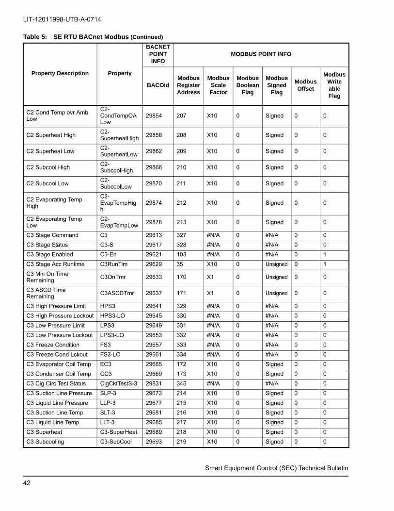
LIT-12011998-UTB-A-0714
Smart Equipment Control (SEC) Technical Bulletin
C2 Cond Temp ovr Amb Low
C2-CondTempOALow
29854 207 X10 0 Signed 0 0
C2 Superheat HighC2-SuperheatHigh 29858 208 X10 0 Signed 0 0
C2 Superheat Low C2-SuperheatLow
29862 209 X10 0 Signed 0 0
C2 Subcool High C2-SubcoolHigh 29866 210 X10 0 Signed 0 0
C2 Subcool LowC2-SubcoolLow 29870 211 X10 0 Signed 0 0
C2 Evaporating Temp High
C2-EvapTempHigh
29874 212 X10 0 Signed 0 0
C2 Evaporating Temp Low
C2-EvapTempLow 29878 213 X10 0 Signed 0 0
C3 Stage Command C3 29613 327 #N/A 0 #N/A 0 0
C3 Stage Status C3-S 29617 328 #N/A 0 #N/A 0 0
C3 Stage Enabled C3-En 29621 103 #N/A 0 #N/A 0 1
C3 Stage Acc Runtime C3RunTim 29629 35 X10 0 Unsigned 0 1
C3 Min On Time Remaining
C3OnTmr 29633 170 X1 0 Unsigned 0 0
C3 ASCD Time Remaining C3ASCDTmr 29637 171 X1 0 Unsigned 0 0
C3 High Pressure Limit HPS3 29641 329 #N/A 0 #N/A 0 0
C3 High Pressure Lockout HPS3-LO 29645 330 #N/A 0 #N/A 0 0
C3 Low Pressure Limit LPS3 29649 331 #N/A 0 #N/A 0 0
C3 Low Pressure Lockout LPS3-LO 29653 332 #N/A 0 #N/A 0 0
C3 Freeze Condition FS3 29657 333 #N/A 0 #N/A 0 0
C3 Freeze Cond Lckout FS3-LO 29661 334 #N/A 0 #N/A 0 0
C3 Evaporator Coil Temp EC3 29665 172 X10 0 Signed 0 0
C3 Condenser Coil Temp CC3 29669 173 X10 0 Signed 0 0
C3 Clg Circ Test Status ClgCktTestS-3 29831 345 #N/A 0 #N/A 0 0
C3 Suction Line Pressure SLP-3 29673 214 X10 0 Signed 0 0
C3 Liquid Line Pressure LLP-3 29677 215 X10 0 Signed 0 0
C3 Suction Line Temp SLT-3 29681 216 X10 0 Signed 0 0
C3 Liquid Line Temp LLT-3 29685 217 X10 0 Signed 0 0
C3 Superheat C3-SuperHeat 29689 218 X10 0 Signed 0 0
C3 Subcooling C3-SubCool 29693 219 X10 0 Signed 0 0
Table 5: SE RTU BACnet Modbus (Continued)
Property Description Property
BACNET POINT INFO
MODBUS POINT INFO
BACOidModbus RegisterAddress
ModbusScaleFactor
Modbus Boolean
Flag
Modbus Signed
Flag
Modbus Offset
Modbus WriteableFlag
42

LIT-12011998-UTB-A-0714
Smart Equipment Control (SEC) Technical Bulletin
C3 Cond Temp over AmbC3-CondTempOvrAmb
29697 220 X10 0 Signed 0 0
C3 Efficiency Index C3-EI 29701 221 X10 0 Signed 0 0
C3 Capacity Index C3-CI 29705 222 X10 0 Signed 0 0
C3 Evap Temp Val CircuitC3-EvapTempValue
29835 223 X10 0 Signed 0 0
C3 Cnd Temp Ovr Amb High
C3-CondTempOAHigh
29851 224 X10 0 Signed 0 0
C3 Cond Temp ovr Amb Low
C3-CondTempOALow
29855 225 X10 0 Signed 0 0
C3 Superheat HighC3-SuperheatHigh 29859 226 X10 0 Signed 0 0
C3 Superheat Low C3-SuperheatLow
29863 227 X10 0 Signed 0 0
C3 Subcool High C3-SubcoolHigh 29867 228 X10 0 Signed 0 0
C3 Subcool LowC3-SubcoolLow 29871 229 X10 0 Signed 0 0
C3 Evaporating Temp High
C3-EvapTempHigh
29875 230 X10 0 Signed 0 0
C3 Evaporating Temp Low
C3-EvapTempLow 29879 231 X10 0 Signed 0 0
C4 Stage Command C4 29614 335 #N/A 0 #N/A 0 0
C4 Stage Status C4-S 29618 336 #N/A 0 #N/A 0 0
C4 Stage Enabled C4-En 29622 104 #N/A 0 #N/A 0 1
C4 Stage Acc Runtime C4RunTim 29630 36 X10 0 Unsigned 0 1
C4 Min On Time Remaining
C4OnTmr 29634 174 X1 0 Unsigned 0 0
C4 ASCD Time Remaining C4ASCDTmr 29638 175 X1 0 Unsigned 0 0
C4 High Pressure Limit HPS4 29642 337 #N/A 0 #N/A 0 0
C4 High Pressure Lockout HPS4-LO 29646 338 #N/A 0 #N/A 0 0
C4 Low Pressure Limit LPS4 29650 339 #N/A 0 #N/A 0 0
C4 Low Pressure Lockout LPS4-LO 29654 340 #N/A 0 #N/A 0 0
C4 Freeze Condition FS4 29658 341 #N/A 0 #N/A 0 0
C4 Freeze Cond Lckout FS4-LO 29662 342 #N/A 0 #N/A 0 0
C4 Evaporator Coil Temp EC4 29666 176 X10 0 Signed 0 0
Table 5: SE RTU BACnet Modbus (Continued)
Property Description Property
BACNET POINT INFO
MODBUS POINT INFO
BACOidModbus RegisterAddress
ModbusScaleFactor
Modbus Boolean
Flag
Modbus Signed
Flag
Modbus Offset
Modbus WriteableFlag
43
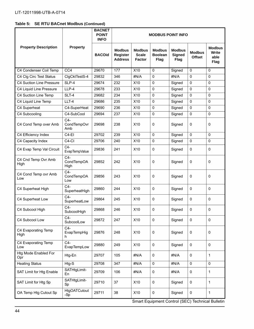
LIT-12011998-UTB-A-0714
Smart Equipment Control (SEC) Technical Bulletin
C4 Condenser Coil Temp CC4 29670 177 X10 0 Signed 0 0
C4 Clg Circ Test Status ClgCktTestS-4 29832 346 #N/A 0 #N/A 0 0
C4 Suction Line Pressure SLP-4 29674 232 X10 0 Signed 0 0
C4 Liquid Line Pressure LLP-4 29678 233 X10 0 Signed 0 0
C4 Suction Line Temp SLT-4 29682 234 X10 0 Signed 0 0
C4 Liquid Line Temp LLT-4 29686 235 X10 0 Signed 0 0
C4 Superheat C4-SuperHeat 29690 236 X10 0 Signed 0 0
C4 Subcooling C4-SubCool 29694 237 X10 0 Signed 0 0
C4 Cond Temp over AmbC4-CondTempOvrAmb
29698 238 X10 0 Signed 0 0
C4 Efficiency Index C4-EI 29702 239 X10 0 Signed 0 0
C4 Capacity Index C4-CI 29706 240 X10 0 Signed 0 0
C4 Evap Temp Val CircuitC4-EvapTempValue 29836 241 X10 0 Signed 0 0
C4 Cnd Temp Ovr Amb High
C4-CondTempOAHigh
29852 242 X10 0 Signed 0 0
C4 Cond Temp ovr Amb Low
C4-CondTempOALow
29856 243 X10 0 Signed 0 0
C4 Superheat High C4-SuperheatHigh 29860 244 X10 0 Signed 0 0
C4 Superheat LowC4-SuperheatLow 29864 245 X10 0 Signed 0 0
C4 Subcool High C4-SubcoolHigh
29868 246 X10 0 Signed 0 0
C4 Subcool Low C4-SubcoolLow 29872 247 X10 0 Signed 0 0
C4 Evaporating Temp High
C4-EvapTempHigh
29876 248 X10 0 Signed 0 0
C4 Evaporating Temp Low
C4-EvapTempLow 29880 249 X10 0 Signed 0 0
Htg Mode Enabled For Opr Htg-En 29707 105 #N/A 0 #N/A 0 1
Heating Status Htg-S 29708 347 #N/A 0 #N/A 0 0
SAT Limit for Htg EnableSATHtgLimit-En 29709 106 #N/A 0 #N/A 0 1
SAT Limit for Htg Sp SATHtgLimit-Sp
29710 37 X10 0 Signed 0 1
OA Temp Htg Cutout Sp HtgOATCutout-Sp 29711 38 X10 0 Signed 0 1
Table 5: SE RTU BACnet Modbus (Continued)
Property Description Property
BACNET POINT INFO
MODBUS POINT INFO
BACOidModbus RegisterAddress
ModbusScaleFactor
Modbus Boolean
Flag
Modbus Signed
Flag
Modbus Offset
Modbus WriteableFlag
44

LIT-12011998-UTB-A-0714
Smart Equipment Control (SEC) Technical Bulletin
Hot Water Freeze Stat FSHW 29712 348 #N/A 0 #N/A 0 0
Gas Valve 1 Input MV 29713 349 #N/A 0 #N/A 0 0
Gas Valve 2 Input GV2 29714 350 #N/A 0 #N/A 0 0
Gas Valve 3 Input GV3 29715 351 #N/A 0 #N/A 0 0
Heat Limit 1 Switch Limit 29716 352 #N/A 0 #N/A 0 0
Heat Limit 1 Sw Lockout LimitLO 29717 353 #N/A 0 #N/A 0 0
Heat Limit 2 Switch Lim2 29718 354 #N/A 0 #N/A 0 0
Heat Limit 2 Sw Lockout Lim2LO 29719 355 #N/A 0 #N/A 0 0
Heat Limit 3 Switch Lim3 29720 356 #N/A 0 #N/A 0 0
Heat Limit 3 Sw Lockout Lim3LO 29721 357 #N/A 0 #N/A 0 0
VAV Occupied Htg Enabled
HtgOcc-En 29722 107 #N/A 0 #N/A 0 1
VAV Occupied Htg Sp VAVHtgOcc-SP 29723 39 X10 0 Signed 0 1
VAV UnOccupied Htg Ena HtgUnocc-En 29724 108 #N/A 0 #N/A 0 1
VAV Unoccupied Htg SpVAVHtgUnocc-Sp 29725 40 X10 0 Signed 0 1
VAV Operating Heating Sp VAVOprHtg-Sp 29726 250 X10 0 Signed 0 0
Morning Warmup Enabled MornW-En 29822 109 #N/A 0 #N/A 0 1
Wrmup-Return Air Temp Sp
MornWRAT-Sp 29823 41 X10 0 Signed 0 1
VAV Box Heat Command VAV 29727 358 #N/A 0 #N/A 0 0
CV Occupied Heating Sp CVHtgOcc-SP 29728 42 X10 0 Signed 0 1
CV Unoccupied Heating Sp
CVHtgUnocc-Sp 29729 43 X10 0 Signed 0 1
CV Operating Heating Sp CVOprHtg-Sp 29730 251 X10 0 Signed 0 0
Morning Cooldown Enabled MornC-En 29891 110 #N/A 0 #N/A 0 1
Cldwn-Return Air Temp Sp
MornCRAT-Sp 29892 44 X10 0 Signed 0 1
Optimal Start Enabled OptStrt-En 29893 111 #N/A 0 #N/A 0 1
Occupancy BI Enabled OccBI-En 29894 112 #N/A 0 #N/A 0 1
Early Start Period EarlyStrtPeriod 29895 45 X10 0 Unsigned 0 1
Heating Adaptive Tuning Enable
HtgAdapTunEn
29881 114 #N/A #N/A #N/A #N/A 1
DAT Max Heating SP DATMaxHtgSP 29905 75 X10 0 Signed 0 0
DAT Satisfied SP DATSatSP 29906 76 X10 0 Signed 0 0
Staged Heating Command StgHtgCmd 29923 264 X10 0 Signed 0 0
Table 5: SE RTU BACnet Modbus (Continued)
Property Description Property
BACNET POINT INFO
MODBUS POINT INFO
BACOidModbus RegisterAddress
ModbusScaleFactor
Modbus Boolean
Flag
Modbus Signed
Flag
Modbus Offset
Modbus WriteableFlag
45

LIT-12011998-UTB-A-0714
Smart Equipment Control (SEC) Technical Bulletin
Number of Heating Stages Installed
#HtgStgs 29731 #N/A #N/A #N/A #N/A #N/A #N/A
Heating Stage 1 Command H1 29732 359 #N/A 0 #N/A 0 0
Heating Stage 1 Status H1-S 29735 360 #N/A 0 #N/A 0 0
Heating Stage 1 Runtime H1RunTim 29738 48 X10 0 Unsigned 0 1
Heating Stage 2 Command H2 29733 361 #N/A 0 #N/A 0 0
Heating Stage 2 Status H2-S 29736 362 #N/A 0 #N/A 0 0
Heating Stage 2 Runtime H2RunTim 29739 49 X10 0 Unsigned 0 1
Heating Stage 3 Command
H3 29734 363 #N/A 0 #N/A 0 0
Heating Stage 3 Status H3-S 29737 364 #N/A 0 #N/A 0 0
Heating Stage 3 Runtime H3RunTim 29740 50 X10 0 Unsigned 0 1
HW Heat Valve Pct Output HWV 29741 252 X10 0 Signed 0 0
HW Heat Valve Rev Acting HydReverse 29742 115 #N/A 0 #N/A 0 1
HW Htg Stage 1 SAT Sp HydH1SA-Sp 29743 51 X10 0 Signed 0 1
HW Htg Stage 2 SAT Sp HydH2SA-Sp 29744 52 X10 0 Signed 0 1
HW Heat SAT Tempring Ena
SATTempHydHt-En
29745 116 #N/A 0 #N/A 0 1
HW Heat SAT Tempering Sp
SATTempHydHt-Sp 29746 53 X10 0 Signed 0 1
Econ Enabled For Oper Econ-En 29747 118 #N/A 0 #N/A 0 1
Econ Damper Pct Output Econ 29748 253 X10 0 Signed 0 0
Econ Free Cooling Avail Econ-Free 29749 369 #N/A 0 #N/A 0 0
Economizer Status Econ-S 29750 370 #N/A 0 #N/A 0 0
Free Clg Current Mode FreeClg-Mode 29751 371 #N/A 0 #N/A 0 0
Free Cooling Selection FreeClg-Sel 29752 119 #N/A 0 #N/A 0 1
Econ OA Temp Enable SpEconOAT-SpEn 29753 55 X10 0 Signed 0 1
Econ OA Enthalpy Sp EconOAEnth-Sp
29754 56 X10 0 Signed 0 1
Low Ambient Econ Sp LowAmb-Sp 29755 57 X10 0 Signed 0 1
Low Ambient Econ Min Pos
LowAmb-MinPos
29756 58 X10 0 Signed 0 1
Econ Damper Position EconDampPos 29824 254 X10 0 Signed 0 0
Mixed Air Temperature MAT 29760 255 X10 0 Signed 0 0
Return Air Humidity RAH 29761 138 X10 0 Unsigned 0 0
Table 5: SE RTU BACnet Modbus (Continued)
Property Description Property
BACNET POINT INFO
MODBUS POINT INFO
BACOidModbus RegisterAddress
ModbusScaleFactor
Modbus Boolean
Flag
Modbus Signed
Flag
Modbus Offset
Modbus WriteableFlag
46
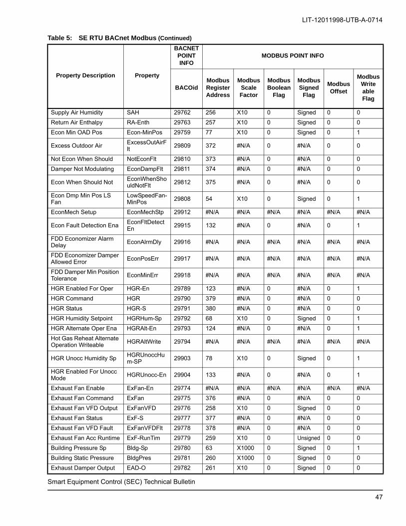
LIT-12011998-UTB-A-0714
Smart Equipment Control (SEC) Technical Bulletin
Supply Air Humidity SAH 29762 256 X10 0 Signed 0 0
Return Air Enthalpy RA-Enth 29763 257 X10 0 Signed 0 0
Econ Min OAD Pos Econ-MinPos 29759 77 X10 0 Signed 0 1
Excess Outdoor Air ExcessOutAirFlt
29809 372 #N/A 0 #N/A 0 0
Not Econ When Should NotEconFlt 29810 373 #N/A 0 #N/A 0 0
Damper Not Modulating EconDampFlt 29811 374 #N/A 0 #N/A 0 0
Econ When Should Not EconWhenShouldNotFlt 29812 375 #N/A 0 #N/A 0 0
Econ Dmp Min Pos LS Fan
LowSpeedFan-MinPos 29808 54 X10 0 Signed 0 1
EconMech Setup EconMechStp 29912 #N/A #N/A #N/A #N/A #N/A #N/A
Econ Fault Detection Ena EconFltDetectEn
29915 132 #N/A 0 #N/A 0 1
FDD Economizer Alarm Delay EconAlrmDly 29916 #N/A #N/A #N/A #N/A #N/A #N/A
FDD Economizer Damper Allowed Error EconPosErr 29917 #N/A #N/A #N/A #N/A #N/A #N/A
FDD Damper Min Position Tolerance
EconMinErr 29918 #N/A #N/A #N/A #N/A #N/A #N/A
HGR Enabled For Oper HGR-En 29789 123 #N/A 0 #N/A 0 1
HGR Command HGR 29790 379 #N/A 0 #N/A 0 0
HGR Status HGR-S 29791 380 #N/A 0 #N/A 0 0
HGR Humidity Setpoint HGRHum-Sp 29792 68 X10 0 Signed 0 1
HGR Alternate Oper Ena HGRAlt-En 29793 124 #N/A 0 #N/A 0 1
Hot Gas Reheat Alternate Operation Writeable HGRAltWrite 29794 #N/A #N/A #N/A #N/A #N/A #N/A
HGR Unocc Humidity SpHGRUnoccHum-SP 29903 78 X10 0 Signed 0 1
HGR Enabled For Unocc Mode
HGRUnocc-En 29904 133 #N/A 0 #N/A 0 1
Exhaust Fan Enable ExFan-En 29774 #N/A #N/A #N/A #N/A #N/A #N/A
Exhaust Fan Command ExFan 29775 376 #N/A 0 #N/A 0 0
Exhaust Fan VFD Output ExFanVFD 29776 258 X10 0 Signed 0 0
Exhaust Fan Status ExF-S 29777 377 #N/A 0 #N/A 0 0
Exhaust Fan VFD Fault ExFanVFDFlt 29778 378 #N/A 0 #N/A 0 0
Exhaust Fan Acc Runtime ExF-RunTim 29779 259 X10 0 Unsigned 0 0
Building Pressure Sp Bldg-Sp 29780 63 X1000 0 Signed 0 1
Building Static Pressure BldgPres 29781 260 X1000 0 Signed 0 0
Exhaust Damper Output EAD-O 29782 261 X10 0 Signed 0 0
Table 5: SE RTU BACnet Modbus (Continued)
Property Description Property
BACNET POINT INFO
MODBUS POINT INFO
BACOidModbus RegisterAddress
ModbusScaleFactor
Modbus Boolean
Flag
Modbus Signed
Flag
Modbus Offset
Modbus WriteableFlag
47

LIT-12011998-UTB-A-0714
Smart Equipment Control (SEC) Technical Bulletin
Exh Dmp Pos Exh Fan-On
ExDmpPosFanOn
29783 64 X10 0 Signed 0 1
Exh Dmp Pos Exh Fan-Off
ExDmpPosFanOff 29784 65 X10 0 Signed 0 1
Econ Dmp Pos-Exh Fan On
EconDmpPosFanOn 29785 66 X10 0 Signed 0 1
Econ Dmp Pos-Exh Fan Off
EconDmpPosFanOff
29786 67 X10 0 Signed 0 1
ERV Enabled ERV-En 29787 121 #N/A 0 #N/A 0 1
ERV Unoccupied Fan Ena ERVUnoccFan-En 29788 122 #N/A 0 #N/A 0 1
Dmd Vent Mode of Oper DVent-Mode 29765 120 #N/A 0 #N/A 0 1
Dmd Vent Max Econ PosDVentMaxEconPos 29766 60 X10 0 Signed 0 1
Dmd Vent IAQ Sp DVentIAQ-Sp 29767 61 X10 0 Signed 0 1
Dmd Vent Differential Sp DVentDiff-Sp 29768 62 X10 0 Signed 0 1
Outdoor Air Flow Sp MOAFlow-Sp 29795 69 X10 0 Signed 0 1
Outdoor Air Flow Fr 29796 262 X10 0 Signed 0 0
OA Intake Max Sensor Rng
MOA-Range 29797 70 X10 0 Signed 0 1
Occupancy Input Source OccSrc 29515 290 #N/A 0 #N/A 0 0
Operational Occupancy OprOcc 29517 292 #N/A 0 #N/A 0 0
Occupancy Enable Mode OccMode 29518 82 #N/A 0 #N/A 0 1
Net Temp Occ Request NetTempOcc 29519 83 #N/A 0 #N/A 0 1
Net Occupancy Request NetOcc 29520 84 #N/A 0 #N/A 0 1
Temp Occupancy Timeout TempOccTimeout 29521 85 #N/A 0 #N/A 0 1
Operational Space Temp OprST 29522 135 X10 0 Signed 0 0
Space Temperature Source STSrc 29523 293 #N/A 0 #N/A 0 0
Space Temp Alm Sp Offset
STAlarmOffset 29524 0 X10 0 Signed 0 1
Space Temp Alrm Time Dly STAlarmDelay 29525 86 #N/A 0 #N/A 0 1
Net Override Space Temp NetST 29526 1 X10 0 Signed 0 1
Oper Indoor Air Quality OprIAQ 29527 136 X10 0 Signed 0 0
Indoor Air Quality Src IAQSrc 29528 294 #N/A 0 #N/A 0 0
Indoor Air Qual Snsr Rng IAQRange 29529 2 X10 0 Signed 0 1
Net Ovrd Indoor Air Qual NetIAQ 29530 3 X10 0 Signed 0 1
Oper Space Humidity OprSH 29531 137 X10 0 Signed 0 0
Table 5: SE RTU BACnet Modbus (Continued)
Property Description Property
BACNET POINT INFO
MODBUS POINT INFO
BACOidModbus RegisterAddress
ModbusScaleFactor
Modbus Boolean
Flag
Modbus Signed
Flag
Modbus Offset
Modbus WriteableFlag
48

LIT-12011998-UTB-A-0714
Smart Equipment Control (SEC) Technical Bulletin
Space Humidity Source SHSrc 29532 295 #N/A 0 #N/A 0 0
Space Humidity/RAH Input
RAH 29828 138 X10 0 Signed 0 0
Net Ovrd Zone Humidity NetSH 29533 4 X10 0 Signed 0 1
Operating Fan Request OprFanReq 29534 296 #N/A 0 #N/A 0 0
Fan Request Source FanReqSrc 29535 297 #N/A 0 #N/A 0 0
Net Ovrd Fan Request NetFanReq 29536 87 #N/A 0 #N/A 0 1
Oper Space Temp Sp Offst OprSSO 29537 140 X10 0 Signed 0 0
Space Temp Sp Offset Src SSOSrc 29538 298 #N/A 0 #N/A 0 0
Space Temp Sp Offst Inpt SSO 29539 141 X10 0 Signed 0 0
Net Ovrd Space Sp Offset NetSSO 29540 5 X10 0 Signed 0 1
Occupancy BI Input OCC 29516 291 #N/A 0 #N/A 0 0
Return Air Temperature RAT 29764 139 X10 0 Signed 0 0
Temporary Occupancy Enable TempOCC 29825 81 #N/A 0 #N/A 0 1
SP LoadShed Enable LoadShedEnable
29883 127 #N/A 0 #N/A 0 1
SP LoadShed Rate Limit LoadShedRateLim 29884 71 X1000 0 Unsigned 0 1
SP LoadShed AdjustLoadShedAdjust 29885 72 X10 0 Unsigned 0 1
Time to Next Occ Period TimeToNextOcc
29837 142 X10 0 Unsigned 0 0
Operating Mode OprMode 29838 299 #N/A 0 #N/A 0 0
Clg Weighting Param 1 ClgWeight1 29839 143 X100 0 Signed 0 0
Clg Weighting Param 2 ClgWeight2 29840 144 X100 0 Signed 0 0
Htg Weighting Param 1 HtgWeight1 29841 145 X100 0 Signed 0 0
Htg Weighting Param 2 HtgWeight2 29842 146 X100 0 Signed 0 0
EWMA Cooling Demand EWMAClgDmd 29843 147 X100 0 Signed 0 0
EWMA Heating Demand EWMAHtgDmd 29844 148 X100 0 Signed 0 0
Corrected Return Time CorrRetTime 29845 149 X10 0 Unsigned 0 0
Uncorrected Return Time UncorrRetTime 29846 150 X10 0 Unsigned 0 0
Wrmup-Cldwn Start Time WarmCoolStrtTime 29847 151 X10 0 Unsigned 0 0
Wrmup-Cldwn Start TempWarmCoolStrtTemp 29848 152 X10 0 Signed 0 0
Off During Unoccupied OffDurUnocc 29914 88 #N/A 0 #N/A 0 1
Direct Loadshed DirLoadshd 29910 128 #N/A 0 #N/A 0 1
Table 5: SE RTU BACnet Modbus (Continued)
Property Description Property
BACNET POINT INFO
MODBUS POINT INFO
BACOidModbus RegisterAddress
ModbusScaleFactor
Modbus Boolean
Flag
Modbus Signed
Flag
Modbus Offset
Modbus WriteableFlag
49

LIT-12011998-UTB-A-0714
Smart Equipment Control (SEC) Technical Bulletin
Redline Redline 29911 129 #N/A 0 #N/A 0 1
PID Tuning Reset PIDTunRst 29919 130 #N/A 0 #N/A 0 1
Operational OA Temp OprOAT 29541 153 X10 0 Signed 0 0
OA Temperature Source OATSrc 29542 300 #N/A 0 #N/A 0 0
Net Ovrd OA Temperature NetOAT 29543 6 X10 0 Signed 0 1
Operational OA Humidity OprOAH 29544 154 X10 0 Signed 0 0
Outdoor Air Enthalpy OA-Enth 29545 155 X10 0 Signed 0 0
Net Override OA Humidity NetOAH 29546 7 X10 0 Signed 0 1
Operational OA Quality OprOAQ 29547 156 X10 0 Signed 0 0
OA Quality Source OAQSrc 29548 301 #N/A 0 #N/A 0 0
Net Override OA Quality NetOAQ 29549 8 X10 0 Signed 0 1
Operating Purge Command
OprPurgeCmd 29798 381 #N/A 0 #N/A 0 0
Purge Command Source PurgeCmdSrc 29799 382 #N/A 0 #N/A 0 0
Local Purge Cmd Input Purge 29800 383 #N/A 0 #N/A 0 0
Net Ovrd Purge Command NetPurge 29801 125 #N/A 0 #N/A 0 1
Smoke Detector SD 29802 384 #N/A 0 #N/A 0 0
Econ Controller EconCntlr 29813 385 #N/A 0 #N/A 0 0
4 Stage Controller 4StgCntlr 29814 386 #N/A 0 #N/A 0 0
FDD Master Controller FDDMCntlr 29815 387 #N/A 0 #N/A 0 0
FDD Slave Controller FDDSCntlr 29816 388 #N/A 0 #N/A 0 0
Device Name DevName 29818 #N/A #N/A #N/A #N/A #N/A #N/A
End of Line Switch On EOL-On 29827 390 #N/A 0 #N/A 0 0
Number of Heat Pump Stages #HtPumpStgs 29898 #N/A #N/A #N/A #N/A #N/A #N/A
Defrost Curve Selection DefrostCurveSel
29899 117 #N/A 0 #N/A 0 1
Defrost State DefrostState 29899 #N/A #N/A #N/A #N/A #N/A #N/A
Reversing Valve RevVlv 29900 366 #N/A 0 #N/A 0 0
Auxiliary Heat AuxHtg 29901 367 #N/A 0 #N/A 0 0
Heat Pump Mode Mode 29902 368 #N/A 0 #N/A 0 0
Table 5: SE RTU BACnet Modbus (Continued)
Property Description Property
BACNET POINT INFO
MODBUS POINT INFO
BACOidModbus RegisterAddress
ModbusScaleFactor
Modbus Boolean
Flag
Modbus Signed
Flag
Modbus Offset
Modbus WriteableFlag
50
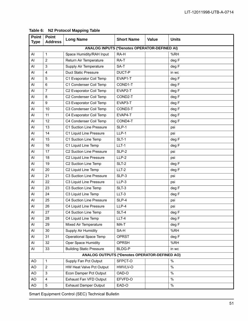
LIT-12011998-UTB-A-0714
Smart Equipment Control (SEC) Technical Bulletin
Table 6: N2 Protocol Mapping Table
PointType
PointAddress
Long Name Short Name Value Units
ANALOG INPUTS (*Denotes OPERATOR-DEFINED AI)
AI 1 Space Humidity/RAH Input RA-H %RH
AI 2 Return Air Temperature RA-T deg F
AI 3 Supply Air Temperature SA-T deg F
AI 4 Duct Static Pressure DUCT-P in wc
AI 5 C1 Evaporator Coil Temp EVAP1-T deg F
AI 6 C1 Condenser Coil Temp COND1-T deg F
AI 7 C2 Evaporator Coil Temp EVAP2-T deg F
AI 8 C2 Condenser Coil Temp COND2-T deg F
AI 9 C3 Evaporator Coil Temp EVAP3-T deg F
AI 10 C3 Condenser Coil Temp COND3-T deg F
AI 11 C4 Evaporator Coil Temp EVAP4-T deg F
AI 12 C4 Condenser Coil Temp COND4-T deg F
AI 13 C1 Suction Line Pressure SLP-1 psi
AI 14 C1 Liquid Line Pressure LLP-1 psi
AI 15 C1 Suction Line Temp SLT-1 deg F
AI 16 C1 Liquid Line Temp LLT-1 deg F
AI 17 C2 Suction Line Pressure SLP-2 psi
AI 18 C2 Liquid Line Pressure LLP-2 psi
AI 19 C2 Suction Line Temp SLT-2 deg F
AI 20 C2 Liquid Line Temp LLT-2 deg F
AI 21 C3 Suction Line Pressure SLP-3 psi
AI 22 C3 Liquid Line Pressure LLP-3 psi
AI 23 C3 Suction Line Temp SLT-3 deg F
AI 24 C3 Liquid Line Temp LLT-3 deg F
AI 25 C4 Suction Line Pressure SLP-4 psi
AI 26 C4 Liquid Line Pressure LLP-4 psi
AI 27 C4 Suction Line Temp SLT-4 deg F
AI 28 C4 Liquid Line Temp LLT-4 deg F
AI 29 Mixed Air Temperature MA-T deg F
AI 30 Supply Air Humidity SA-H %RH
AI 31 Operational Space Temp OPRST deg F
AI 32 Oper Space Humidity OPRSH %RH
AI 33 Building Static Pressure BLDG-P in wc
ANALOG OUTPUTS (*Denotes OPERATOR-DEFINED AO)
AO 1 Supply Fan Pct Output SFPCT-O %
AO 2 HW Heat Valve Pct Output HWVLV-O %
AO 3 Econ Damper Pct Output OAD-O %
AO 4 Exhaust Fan VFD Output EFVFD-O %
AO 5 Exhaust Damper Output EAD-O %
51

LIT-12011998-UTB-A-0714
Smart Equipment Control (SEC) Technical Bulletin
BINARY INPUTS (*Denotes OPERATOR-DEFINED BI)
BI 1 Y1 - Thermostat Y1-TSTAT Off/On
BI 2 Y2 - Thermostat Y2-TSTAT Off/On
BI 3 Y3 - Thermostat Y3-TSTAT Off/On
BI 4 Y4 - Thermostat Y4-TSTAT Off/On
BI 5 W1 - Thermostat W1-TSTAT Off/On
BI 6 W2 - Thermostat W2-TSTAT Off/On
BI 7 W3 - Thermostat W3-TSTAT Off/On
BI 8 G - Thermostat G-TSTAT Off/On
BI 9 Occupancy BI Input OCC-S SE RTU Unocc/Occ
BI 10 Fan VFD Fault FNVFDFLT Normal/Alarm
BI 11 Supply Fan Overload FAN-OL Normal/Alarm
BI 12 Air Proving Switch APS Off/On
BI 13 Dirty Filter Switch FILTER-S Normal/Alarm
BI 14 C1 Stage Status COMP1-S SE RTU DX Cooling Circuit 1 Status
BI 15 C1 High Pressure Limit HPS1-S Normal/Alarm
BI 16 C1 Low Pressure Limit LPS1-S Normal/Alarm
BI 17 C1 Freeze Condition FS1-S Normal/Alarm
BI 18 C2 Stage Status COMP2-S SE RTU DX Cooling Circuit 1 Status
BI 19 C2 High Pressure Limit HPS2-S Normal/Alarm
BI 20 C2 Low Pressure Limit LPS2-S Normal/Alarm
BI 21 C2 Freeze Condition FS2-S Normal/Alarm
BI 22 C3 Stage Status COMP3-S SE RTU DX Cooling Circuit 1 Status
BI 23 C3 High Pressure Limit HPS3-S Normal/Alarm
BI 24 C3 Low Pressure Limit LPS3-S Normal/Alarm
BI 25 C3 Freeze Condition FS3-S Normal/Alarm
BI 26 C4 Stage Status COMP4-S SE RTU DX Cooling Circuit 1 Status
BI 27 C4 High Pressure Limit HPS4-S Normal/Alarm
BI 28 C4 Low Pressure Limit LPS4-S Normal/Alarm
BI 29 C4 Freeze Condition FS4-S Normal/Alarm
BI 30 Gas Valve 1 Input GV1-S Off/On
BI 31 Gas Valve 2 Input GV2-S Off/On
BI 32 Gas Valve 3 Input GV3-S Off/On
BI 33 Heat Limit 1 Switch LIM1-SW Normal/Alarm
BI 34 Heat Limit 2 Switch LIM2-SW Normal/Alarm
BI 35 Heat Limit 3 Switch LM3-SW Normal/Alarm
BI 36 Heating Stage 1 Status H1-S SE RTU Heating Stage 1 Status
BI 37 Heating Stage 2 Status H2-S SE RTU Heating Stage 1 Status
BI 38 Heating Stage 3 Status H3-S SE RTU Heating Stage 1 Status
BI 39 Exhaust Fan Status EXHFAN-S SE RTU Exhaust Fan
BI 40 Exhaust Fan VFD Fault EFVFDFLT Normal/Alarm
Table 6: N2 Protocol Mapping Table (Continued)
PointType
PointAddress
Long Name Short Name Value Units
52

LIT-12011998-UTB-A-0714
Smart Equipment Control (SEC) Technical Bulletin
BI 41 HGR Status HGR-S SE RTU Hot Gas Reheat
BINARY OUTPUTS (*Denotes OPERATOR-DEFINED BO)
BO 1 X-OUT X-C Off/On
BO 2 Fan Command FAN-C Off/On
BO 3 Condenser Fan 1 CF1-C Off/On
BO 4 Condenser Fan 2 CF2-C Off/On
BO 5 C1 Stage Command COMP1-C Off/On
BO 6 C2 Stage Command COMP2-C Off/On
BO 7 C3 Stage Command COMP3-C Off/On
BO 8 C4 Stage Command COMP4-C Off/On
BO 9 VAV Box Heat Command VAVBOX-C Off/On
BO 10 Heating Stage 1 Command H1-C Off/On
BO 11 Heating Stage 2 Command H2-C Off/On
BO 12 Heating Stage 3 Command H3-C Off/On
BO 13 Reversing Valve REVVLV-C Off/On
BO 14 Auxiliary Heat AUXHTG-C Off/On
BO 15 Exhaust Fan Command EXHFAN-C Off/On
BO 16 HGR Command HGR-C Off/On
PARAMETERS (* Denotes MONITOR ONLY Parameters)
York RTU
ADI 1 Unit Status UNIT-S SE RTU Unit Status
ADI 2 Reset Lockouts RESETLO Off Off/Reset
ADI 109 Hardware Reset HDW-RST No/Yes
HVAC Zone
ADI 3 Occupancy Input Source OCCSRC Effective Occupancy Source
ADI 4 Temporary Occupancy Ena TEMPOCCEN No/Yes
ADI 5 Operational Occupancy OPROCC Occ Effective
ADI 6 Occupancy Enable Mode OCCENMODE External SE Occupancy Mode
ADI 7 Net Temp Occ Request NETTMPOC Unreliable] False/True
ADI 8 Net Occupancy Request NETOCCRQ Unreliable] Occ Sensor
ADI 9 Temp Occupancy Timeout TMPOCCTO 120 min
ADI 10 Space Temperature Source STSRC Effective Input Source
ADF 2 Space Temp Alm Sp Offset STALMOFF 5 °F delta
ADI 11 Space Temp Alrm Time Dly STALMDLY 60 min
ADF 3 Net Override Space Temp NETST Unreliable] deg F
ADF 4 Oper Indoor Air Quality OPRIAQ ppm
ADI 12 Indoor Air Quality Src IAQSRC Effective Input Source 2
ADF 5 Indoor Air Qual Snsr Rng IAQRANGE 2000 ppm
ADF 6 Net Ovrd Indoor Air Qual NETIAQ Unreliable] ppm
ADI 13 Space Humidity Source SHSRC Effective Input Source 2
ADF 8 Net Ovrd Zone Humidity NETSH Unreliable] %RH
Table 6: N2 Protocol Mapping Table (Continued)
PointType
PointAddress
Long Name Short Name Value Units
53
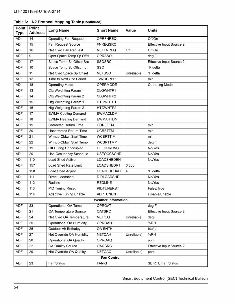
LIT-12011998-UTB-A-0714
ADI 14 Operating Fan Request OPRFNREQ Off/On
ADI 15 Fan Request Source FNREQSRC Effective Input Source 2
ADI 16 Net Ovrd Fan Request NETFNREQ Off Off/On
ADF 9 Oper Space Temp Sp Offst OPRSSO deg F
ADI 17 Space Temp Sp Offset Src SSOSRC Effective Input Source 2
ADF 10 Space Temp Sp Offst Inpt SSO °F delta
ADF 11 Net Ovrd Space Sp Offset NETSSO Unreliable] °F delta
ADF 12 Time to Next Occ Period T2NOCPER min
ADI 18 Operating Mode OPERMODE Operating Mode
ADF 13 Clg Weighting Param 1 CLGWHTP1
ADF 14 Clg Weighting Param 2 CLGWHTP2
ADF 15 Htg Weighting Param 1 HTGWHTP1
ADF 16 Htg Weighting Param 2 HTGWHTP2
ADF 17 EWMA Cooling Demand EWMACLDM
ADF 18 EWMA Heating Demand EWMAHTDM
ADF 19 Corrected Return Time CORETTM min
ADF 20 Uncorrected Return Time UCRETTM min
ADF 21 Wrmup-Cldwn Start Time WCSRTTIM min
ADF 22 Wrmup-Cldwn Start Temp WCSRTTMP deg F
ADI 19 Off During Unoccupied OFFDURUNC No/Yes
ADI 20 Use Occupancy Schedule USEOCCSCHD No/Yes
ADI 110 Load Shed Active LOADSHEDEN No/Yes
ADF 157 Load Shed Rate Limit LOADSHEDRT 0.666
ADF 158 Load Shed Adjust LOADSHEDAD 4 °F delta
ADI 111 Direct Loadshed DIRLOADSHD No/Yes
ADI 112 Redline REDLINE No/Yes
ADI 113 PID Tuning Reset PIDTUNERST False/True
ADI 114 Adaptive Tuning Enable ADPTUNEN Disable/Enable
Weather Information
ADF 23 Operational OA Temp OPROAT deg F
ADI 21 OA Temperature Source OATSRC Effective Input Source 2
ADF 24 Net Ovrd OA Temperature NETOAT Unreliable] deg F
ADF 25 Operational OA Humidity OPROAH %RH
ADF 26 Outdoor Air Enthalpy OA-ENTH btu/lb
ADF 27 Net Override OA Humidity NETOAH Unreliable] %RH
ADF 28 Operational OA Quality OPROAQ ppm
ADI 22 OA Quality Source OAQSRC Effective Input Source 2
ADF 29 Net Override OA Quality NETOAQ Unreliable] ppm
Fan Control
ADI 23 Fan Status FAN-S SE RTU Fan Status
Table 6: N2 Protocol Mapping Table (Continued)
PointType
PointAddress
Long Name Short Name Value Units
Smart Equipment Control (SEC) Technical Bulletin
54

LIT-12011998-UTB-A-0714
Smart Equipment Control (SEC) Technical Bulletin
ADF 30 Fan Accumulated Runtime FAN-RT 0 hr
ADI 24 Fan On Delay for Cool FNONDLCL 0 sec
ADF 31 Duct Pressure Setpoint DCTPRSSP 1.5 in wc
ADF 32 Duct Pressure Shutdwn Sp DCTSDSP 4.5 in wc
ADI 25 Cont SF Oper in Occ Mode FANONOCC Yes Yes/No
ADI 26 Trn Off Cnt Fn Opr St Ht FNOFSTHT Yes Yes/No
ADF 33 Occ No Heat or Cl Pct Sp FOPCT 50 %
ADF 34 Occ 1 Stage of Cl Pct Sp 1CSPCT 70 %
ADF 35 Occ 2 Stges of Cl Pct Sp 2CSPCT 80 %
ADF 36 Occ 3 Stges of Cl Pct Sp 3CSPCT 90 %
ADF 37 Occ 4 Stges of Cl Pct Sp 4CSPCT 100 %
ADF 38 Occ 1 Stage of Ht Pct Sp 1HSPCT 100 %
ADF 39 Occ 2 Stges of Ht Pct Sp 2HSPCT 100 %
ADF 40 Occ 3 Stges of Ht Pct Sp 3HSPCT 100 %
ADF 159 SZ VAV Minimum Fan Speed SZVMNFNSPD 66 %
Cooling Control
ADI 27 Clg Mode Ena For Oper CLG-EN Yes No/Yes
ADI 28 Cooling Status CLG-S SE RTU Cooling Control Status
ADF 41 Min Runtime Clg Stage MNRTCLST 3 min
ADI 29 OAT Cooling Cutout Ena CLOACOEN Yes No/Yes
ADF 42 OAT Cooling Cutout CLOACOSP 45 deg F
ADI 30 Economizer Loading Ena ECNLD-EN No No/Yes
ADI 31 All Stgs Clg Off in Econ CLOFFECN No No/Yes
ADI 32 Temp/Hum (Ret) Cntrl Ena THCTRLEN No No/Yes
ADF 43 Temp/Humidity Sp TEMPHMSP 50 %RH
ADF 44 Max Temp / Hum Sp Offset MXTHSPOF 3 °F delta
ADF 45 Temp-Hum Value-Deg Offst THVDGOFF 5 %RH
ADI 33 SAT Limit for Clg Ena SATCLMEN Yes No/Yes
ADF 46 SAT Limit for Cooling Sp SATCLMSP 50 deg F
ADF 47 VAV Clg SA Temp Upper Sp SATUP-SP 60 deg F
ADF 48 VAV Cig SA Temp Lower Sp SATLO-SP 55 deg F
ADF 49 VAV SA Temp Reset Sp SATRSTSP 72 deg F
ADF 50 VAV Oper Clg SA Temp Sp OPRVAVCLSP deg F
ADF 51 CV Occupied Cooling Sp CLGOCCSP 72 deg F
ADF 52 CV Unoccupied Cooling Sp CLGUNCSP 85 deg F
ADF 53 CV Operating Cooling Sp COPCLGSP deg F
ADF 54 Altitude ALTITUDE 0 ft
ADF 55 Refrig Systems Installed REFSYS 4
ADF 160 DAT Cooling Min SP DATCLMSP 54 0 deg F
ADF 165 Staged Cooling Command STGCLGCMD %
ADF 168 VAV Unoccupied Clg Sp VCLGUNCSP 85 deg F
Table 6: N2 Protocol Mapping Table (Continued)
PointType
PointAddress
Long Name Short Name Value Units
55

LIT-12011998-UTB-A-0714
Smart Equipment Control (SEC) Technical Bulletin
Cooling Circuit (1)
ADI 36 C1 Stage Enabled C1-EN Yes Yes/No
ADF 56 C1 Stage Acc Runtime C1-RT 0 hr
ADI 37 C1 Min On Time Remaining C1ONTMR min
ADI 38 C1 ASCD Time Remaining C1ASCDTM min
ADI 39 C1 High Pressure Lockout HPS1-LO Normal Lockout
ADI 40 C1 Low Pressure Lockout LPS1-LO Normal Lockout
ADI 41 C1 Freeze Cond Lckout FS1-LO Normal Lockout
Cooling Circuit (2)
ADI 42 C2 Stage Enabled C2-EN Yes Yes/No
ADF 57 C2 Stage Acc Runtime C2-RT 0 hr
ADI 43 C2 Min On Time Remaining C2ONTMR min
ADI 44 C2 ASCD Time Remaining C2ASCDTM min
ADI 45 C2 High Pressure Lockout HPS2-LO Normal Lockout
ADI 46 C2 Low Pressure Lockout LPS2-LO Normal Lockout
ADI 47 C2 Freeze Cond Lckout FS2-LO Normal Lockout
Cooling Circuit (3)
ADI 48 C3 Stage Enabled C3-EN Yes Yes/No
ADF 58 C3 Stage Acc Runtime C3-RT 0 hr
ADI 49 C3 Min On Time Remaining C3ONTMR min
ADI 50 C3 ASCD Time Remaining C3ASCDTM min
ADI 51 C3 High Pressure Lockout HPS3-LO Normal Lockout
ADI 52 C3 Low Pressure Lockout LPS3-LO Normal Lockout
ADI 53 C3 Freeze Cond Lckout FS3-LO Normal Lockout
Cooling Circuit (4)
ADI 54 C4 Stage Enabled C4-EN Yes Yes/No
ADF 59 C4 Stage Acc Runtime C4-RT 0 hr
ADI 55 C4 Min On Time Remaining C4ONTMR min
ADI 56 C4 ASCD Time Remaining C4ASCDTM min
ADI 57 C4 High Pressure Lockout HPS4-LO Normal Lockout
ADI 58 C4 Low Pressure Lockout LPS4-LO Normal Lockout
ADI 59 C4 Freeze Cond Lckout FS4-LO Normal Lockout
Cooling Circuit Diagnostics (1)
ADI 60 C1 Clg Circ Test Status C1-TS SE FDD Codes
ADF 60 C1 Superheat C1-SUPHT deg F
ADF 61 C1 Subcooling C1-SUBCL deg F
ADF 62 C1 Cond Temp over Amb CT1O-AMB deg F
ADF 63 C1 Efficiency Index C1-EI
ADF 64 C1 Capacity Index C1-CI
ADF 65 C1 Evap Temp Val Circuit C1-ETVAL deg F
ADF 66 C1 Cnd Temp Ovr Amb High CT1OAMBH deg F
Table 6: N2 Protocol Mapping Table (Continued)
PointType
PointAddress
Long Name Short Name Value Units
56

LIT-12011998-UTB-A-0714
ADF 67 C1 Cond Temp ovr Amb Low CT1OAMBL deg F
ADF 68 C1 Superheat High C1-SUPHH deg F
ADF 69 C1 Superheat Low C1-SUPHL deg F
ADF 70 C1 Subcool High C1-SCHGH deg F
ADF 71 C1 Subcool Low C1-SCLOW deg F
ADF 72 C1 Evaporating Temp High C1-ETHGH deg F
ADF 73 C1 Evaporating Temp Low C1-ETLOW deg F
Cooling Circuit Diagnostics (2)
ADI 61 C2 Clg Circ Test Status C2-TS SE FDD Codes
ADF 74 C2 Superheat C2-SUPHT deg F
ADF 75 C2 Subcooling C2-SUBCL deg F
ADF 76 C2 Cond Temp over Amb CT2O-AMB deg F
ADF 77 C2 Efficiency Index C2-EI
ADF 78 C2 Capacity Index C2-CI
ADF 79 C2 Evap Temp Val Circuit C2-ETVAL deg F
ADF 80 C2 Cnd Temp Ovr Amb High CT2OAMBH deg F
ADF 81 C2 Cond Temp ovr Amb Low CT2OAMBL deg F
ADF 82 C2 Superheat High C2-SUPHH deg F
ADF 83 C2 Superheat Low C2-SUPHL deg F
ADF 84 C2 Subcool High C2-SCHGH deg F
ADF 85 C2 Subcool Low C2-SCLOW deg F
ADF 86 C2 Evaporating Temp High C2-ETHGH deg F
ADF 87 C2 Evaporating Temp Low C2-ETLOW deg F
Cooling Circuit Diagnostics (3)
ADI 62 C3 Clg Circ Test Status C3-TS SE FDD Codes
ADF 88 C3 Superheat C3-SUPHT deg F
ADF 89 C3 Subcooling C3-SUBCL deg F
ADF 90 C3 Cond Temp over Amb CT3O-AMB deg F
ADF 91 C3 Efficiency Index C3-EI
ADF 92 C3 Capacity Index C3-CI
ADF 93 C3 Evap Temp Val Circuit C3-ETVAL deg F
ADF 94 C3 Cnd Temp Ovr Amb High CT3OAMBH deg F
ADF 95 C3 Cond Temp ovr Amb Low CT3OAMBL deg F
ADF 96 C3 Superheat High C3-SUPHH deg F
ADF 97 C3 Superheat Low C3-SUPHL deg F
ADF 98 C3 Subcool High C3-SCHGH deg F
ADF 99 C3 Subcool Low C3-SCLOW deg F
ADF 100 C3 Evaporating Temp High C3-ETHGH deg F
ADF 101 C3 Evaporating Temp Low C3-ETLOW deg F
Table 6: N2 Protocol Mapping Table (Continued)
PointType
PointAddress
Long Name Short Name Value Units
Smart Equipment Control (SEC) Technical Bulletin
57

LIT-12011998-UTB-A-0714
Cooling Circuit Diagnostics (4)
ADI 63 C4 Clg Circ Test Status C4-TS SE FDD Codes
ADF 102 C4 Superheat C4-SUPHT deg F
ADF 103 C4 Subcooling C4-SUBCL deg F
ADF 104 C4 Cond Temp over Amb CT4O-AMB deg F
ADF 105 C4 Efficiency Index C4-EI
ADF 106 C4 Capacity Index C4-CI
ADF 107 C4 Evap Temp Val Circuit C4-ETVAL deg F
ADF 108 C4 Cnd Temp Ovr Amb High CT4OAMBH deg F
ADF 109 C4 Cond Temp ovr Amb Low CT4OAMBL deg F
ADF 110 C4 Superheat High C4-SUPHH deg F
ADF 111 C4 Superheat Low C4-SUPHL deg F
ADF 112 C4 Subcool High C4-SCHGH deg F
ADF 113 C4 Subcool Low C4-SCLOW deg F
ADF 114 C4 Evaporating Temp High C4-ETHGH deg F
ADF 115 C4 Evaporating Temp Low C4-ETLOW deg F
Heating Control
ADI 64 Htg Mode Enabled For Opr HTG-EN Yes No/Yes
ADI 65 Heating Status HTG-S SE RTU Heating Control Status
ADI 66 SAT Limit for Htg Enable SATHL-EN Yes No/Yes
ADF 116 SAT Limit for Htg Sp SATHL-SP 135 deg F
ADF 117 OA Temp Htg Cutout Sp OATHCOSP 75 deg F
ADI 67 Hot Water Freeze Stat FSHW Normal/Alarm
ADI 68 Heat Limit 1 Sw Lockout LIMIT1LO Normal Lockout
ADI 69 Heat Limit 2 Sw Lockout LIMIT2LO Normal Lockout
ADI 70 Heat Limit 3 Sw Lockout LIMIT3LO Normal Lockout
ADI 71 VAV Occupied Htg Enabled VHTGOCEN No No/Yes
ADF 118 VAV Occupied Htg Sp VHTGOCSP 68 deg F
ADI 72 VAV UnOccupied Htg Ena VHTGUNEN No No/Yes
ADF 119 VAV Unoccupied Htg Sp VHTGUNSP 60 deg F
ADF 120 VAV Operating Heating Sp VOPHTGSP deg F
ADI 73 Morning Warmup Enabled MRNWRMEN No No/Yes
ADF 121 Wrmup-Return Air Temp Sp WRMRATSP 70 deg F
ADF 122 CV Occupied Heating Sp CVHTOCSP 68 deg F
ADF 123 CV Unoccupied Heating Sp CVHTUNSP 60 deg F
ADF 124 CV Operating Heating Sp CVHTOPSP deg F
ADI 74 Morning Cooldown Enabled MRNCLDEN No No/Yes
ADF 125 Cldwn-Return Air Temp Sp CLDRATSP 74 deg F
ADI 75 Optimal Start Enabled OST-EN No No/Yes
ADI 76 Occupancy BI Enabled OCCBI-EN No No/Yes
Table 6: N2 Protocol Mapping Table (Continued)
PointType
PointAddress
Long Name Short Name Value Units
Smart Equipment Control (SEC) Technical Bulletin
58
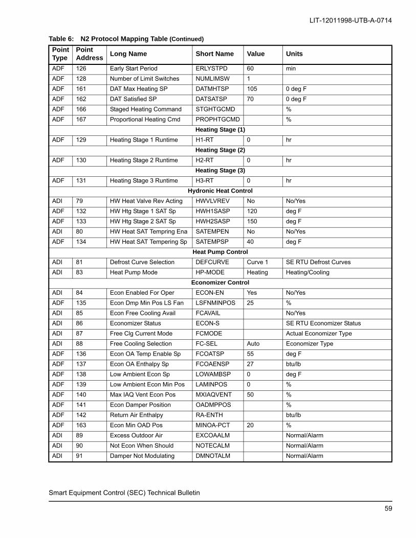
LIT-12011998-UTB-A-0714
ADF 126 Early Start Period ERLYSTPD 60 min
ADF 128 Number of Limit Switches NUMLIMSW 1
ADF 161 DAT Max Heating SP DATMHTSP 105 0 deg F
ADF 162 DAT Satisfied SP DATSATSP 70 0 deg F
ADF 166 Staged Heating Command STGHTGCMD %
ADF 167 Proportional Heating Cmd PROPHTGCMD %
Heating Stage (1)
ADF 129 Heating Stage 1 Runtime H1-RT 0 hr
Heating Stage (2)
ADF 130 Heating Stage 2 Runtime H2-RT 0 hr
Heating Stage (3)
ADF 131 Heating Stage 3 Runtime H3-RT 0 hr
Hydronic Heat Control
ADI 79 HW Heat Valve Rev Acting HWVLVREV No No/Yes
ADF 132 HW Htg Stage 1 SAT Sp HWH1SASP 120 deg F
ADF 133 HW Htg Stage 2 SAT Sp HWH2SASP 150 deg F
ADI 80 HW Heat SAT Tempring Ena SATEMPEN No No/Yes
ADF 134 HW Heat SAT Tempering Sp SATEMPSP 40 deg F
Heat Pump Control
ADI 81 Defrost Curve Selection DEFCURVE Curve 1 SE RTU Defrost Curves
ADI 83 Heat Pump Mode HP-MODE Heating Heating/Cooling
Economizer Control
ADI 84 Econ Enabled For Oper ECON-EN Yes No/Yes
ADF 135 Econ Dmp Min Pos LS Fan LSFNMINPOS 25 %
ADI 85 Econ Free Cooling Avail FCAVAIL No/Yes
ADI 86 Economizer Status ECON-S SE RTU Economizer Status
ADI 87 Free Clg Current Mode FCMODE Actual Economizer Type
ADI 88 Free Cooling Selection FC-SEL Auto Economizer Type
ADF 136 Econ OA Temp Enable Sp FCOATSP 55 deg F
ADF 137 Econ OA Enthalpy Sp FCOAENSP 27 btu/lb
ADF 138 Low Ambient Econ Sp LOWAMBSP 0 deg F
ADF 139 Low Ambient Econ Min Pos LAMINPOS 0 %
ADF 140 Max IAQ Vent Econ Pos MXIAQVENT 50 %
ADF 141 Econ Damper Position OADMPPOS %
ADF 142 Return Air Enthalpy RA-ENTH btu/lb
ADF 163 Econ Min OAD Pos MINOA-PCT 20 %
ADI 89 Excess Outdoor Air EXCOAALM Normal/Alarm
ADI 90 Not Econ When Should NOTECALM Normal/Alarm
ADI 91 Damper Not Modulating DMNOTALM Normal/Alarm
Table 6: N2 Protocol Mapping Table (Continued)
PointType
PointAddress
Long Name Short Name Value Units
Smart Equipment Control (SEC) Technical Bulletin
59
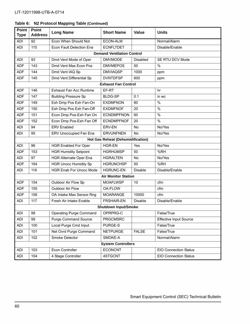
LIT-12011998-UTB-A-0714
ADI 92 Econ When Should Not ECON-ALM Normal/Alarm
ADI 115 Econ Fault Detection Ena ECNFLTDET Disable/Enable
Demand Ventilation Control
ADI 93 Dmd Vent Mode of Oper DMVMODE Disabled SE RTU DCV Mode
ADF 143 Dmd Vent Max Econ Pos DMVMEPOS 50 %
ADF 144 Dmd Vent IAQ Sp DMVIAQSP 1000 ppm
ADF 145 Dmd Vent Differential Sp DVNTDFSP 600 ppm
Exhaust Fan Control
ADF 146 Exhaust Fan Acc Runtime EF-RT hr
ADF 147 Building Pressure Sp BLDG-SP 0.1 in wc
ADF 149 Exh Dmp Pos Exh Fan-On EXDMFNON 80 %
ADF 150 Exh Dmp Pos Exh Fan-Off EXDMFNOF 20 %
ADF 151 Econ Dmp Pos-Exh Fan On ECNDMPFNON 60 %
ADF 152 Econ Dmp Pos-Exh Fan Off ECNDMPFNOF 20 %
ADI 94 ERV Enabled ERV-EN No No/Yes
ADI 95 ERV Unoccupied Fan Ena ERVUNFNEN No No/Yes
Hot Gas Reheat (Dehumidification)
ADI 96 HGR Enabled For Oper HGR-EN Yes No/Yes
ADF 153 HGR Humidity Setpoint HGRHUMSP 50 %RH
ADI 97 HGR Alternate Oper Ena HGRALTEN No No/Yes
ADF 164 HGR Unocc Humidity Sp HGRUNCHSP 50 %RH
ADI 116 HGR Enab For Unocc Mode HGRUNC-EN Disable Disable/Enable
Air Monitor Station
ADF 154 Outdoor Air Flow Sp MOAFLWSP 10 cfm
ADF 155 Outdoor Air Flow OA-FLOW cfm
ADF 156 OA Intake Max Sensor Rng MOARANGE 10000 cfm
ADI 117 Fresh Air Intake Enable FRSHAIR-EN Disable Disable/Enable
Shutdown Input/Smoke
ADI 98 Operating Purge Command OPRPRG-C False/True
ADI 99 Purge Command Source PRGCMSRC Effective Input Source
ADI 100 Local Purge Cmd Input PURGE-S False/True
ADI 101 Net Ovrd Purge Command NETPURGE FALSE False/True
ADI 102 Smoke Detector SMOKE-A Normal/Alarm
System Controllers
ADI 103 Econ Controller ECONCNT EIO Connection Status
ADI 104 4 Stage Controller 4STGCNT EIO Connection Status
Table 6: N2 Protocol Mapping Table (Continued)
PointType
PointAddress
Long Name Short Name Value Units
Smart Equipment Control (SEC) Technical Bulletin
60

ADI 105 FDD Master Controller FDDMCNT EIO Connection Status
ADI 106 FDD Slave Controller FDDSCNT EIO Connection Status
ADI 107 Stepped Heat Controller STPHTCNT EIO Connection Status
Network
ADI 108 End of Line Switch On EOL-ON No/Yes
Table 6: N2 Protocol Mapping Table (Continued)
PointType
PointAddress
Long Name Short Name Value Units
0000000-UTB-A-0714Subject to change without notice. Printed in U.S.A. Ref: 12011444Copyright © February 19, 2015 by Johnson Controls, Inc. All rights reserved. Supersedes: Nothing
York International Corporation5005 York Drive
Norman, OK 73069