Embed Size (px)
Citation preview

Smart Door Monitoring and Locking System
using SIM900 GSM Shield and Arduino UNO
Sialee Leekongxue School of Electronic Engineering
Tianjin University of Technology
and Education, Tianjin, China
Li Li Tianjin University of Technology
and Education,
Tianjin, China
Tomas Page Beijing International Education
Institute
Beijing, China
Abstract—The problem with the safety of people’s belongings at
home is among some of the most important security problems to
solve. One way of knowing that a house is safe is the door
because when the door is locked, the house is safe. Hence, an
attempt has been made here to develop a smart door that
monitors the door state, sends an SMS to the owner when
someone opens the door without unlocking it, the door can be
locked and unlocked by sending an SMS from a mobile phone.
One more feature is a lamp that can be switched on and off and
will switch on when the door is unlocked and switch off when
the door is locked. This system comprises an Arduino UNO,
GSM Technology and other electronics components. The system
has been successfully developed, implemented and tested in the
laboratory and the result shows that it works as intended. This
system is suitable for all kinds of houses and has been designed
to be very economical so that it can be afforded by all.
Keywords— Arduino Uno; SIM900 GSM; Smart Door; SMS
Notification.
I. INTRODUCTION
People use different kinds of security devices to provide
protection to their life and assets. Ensuring safety and security
of people and their valuables in the home is most important
for avoiding illegal intrusion and theft [1]. Most people use
key locks for the door of their homes, their lockers, cabinets,
and other things. However, key locks can be easily broken and
compromised by determined thieves and intruders. Therefore,
as means of addressing this problem is to allow the people
know the lock state such as the lock is locked, unlocked, the
door is opened and closed using a smart door monitoring and
locking system. This system will save all the states of the lock,
the door and the lamp in the house. The owner can check the
states by sending an SMS from a mobile phone and it will
send an SMS to the owner when someone goes into the house
without unlocking the lock or break the look. This system can
also send an SMS to lock and unlock the door and switch the
lamp on and off.
II. LITERATURE SURVEY ON EARLIER WORKS
The related works that use GSM technology and Arduino
UNO are presented as the work describes the development of
GSM based advanced alert home locker safety security system
using the Arduino and SIM900 [2]. Back locker security
system using RFID and GSM technology [3]. Advanced
locker security system based on RFID, password and GSM
technology with automatic movement of lock system [4].
Implemented a home security system with a GSM module
with a microcontroller [5]. The locker opening and closing
system with RFID, Fingerprint, Password, and GSM [6].
Smart home automation and security system using Arduino
and IOT [7]. The web site Ran Dom Nerd Tutorials has made
the project about control a 12V lamp via SMS with Arduino
[8].
III. DEVELOPMENT
This project’s software development is based on the C++
programing language using the Arduino IDE and installing it
on an Arduino UNO board. The Block Diagram of the Smart
Door Monitoring and Locking System is shown in figure 1
and the schematic diagram is in figure 2. This System consists
of the main following units. There are:
Arduino UNO
SIM900 GSM shield
Servo Motor
Relay and Lamp
Door Sensor
Figure. 1. Block diagram of the Smart Door Monitoring and Locking
System.
A. Arduino UNO
The Arduino Uno is a microcontroller breakout board
based on the ATmega328P (datasheet). It has 14 digital
input/output pins, 6 analog inputs, a 16 MHz quartz crystal, a
USB connection, a power jack, an ICSP header and a reset
button. It contains everything needed to support the
microcontroller, simply connect it to a computer with a USB
cable or power it with an AC-to-DC adapter or battery to get
started [9].
IJERTV9IS040011(This work is licensed under a Creative Commons Attribution 4.0 International License.)
www.ijert.org 47
International Journal of Engineering Research & Technology (IJERT)
ISSN: 2278-0181http://www.ijert.org
Published by :
Vol. 9 Issue 04, April-2020

Figure 2. Schematic diagram of the Smart Door Monitoring and Locking
System.
Arduino is an open-source platform and consists of both a
physical programmable circuit. It has the IDE (Integrated
Development Environment) that runs on a computer, used to
write and upload computer code to the physical board.
The board is shown in figure 3 and the features are shown
below.
Operating Voltage: 5V
Digital I/O Pins: 14 (of which 6 provide PWM
output)
Analog Input Pins: 6
DC Current for 3.3V Pin:50 mA
DC Current per I/O Pin: 40 mA
Clock Speed: 16 MHz
EEPROM: 1 KB
SRAM:2 KB
Flash Memory: 32 KB of which 0.5 KB used by the
boot loader
Fig. 3. Arduino UNO board.
B. SIM900 GSM Shield
SIM900 GSM/GPRS shield is a GSM modem specifically
designed for the Arduino UNO, which can be integrated into a
great number of IoT projects. This shield can be used to
accomplish almost anything a normal cell phone can; SMS
text messages, make or receive phone calls, connecting to the
internet through GPRS, TCP/IP, and more! To top it off, the
shield supports quad-band GSM/GPRS network, meaning it
works pretty much anywhere in the world [10]. The SIM900
board is shown in figure 4.
Fig. 4. SIM900 GSM/GPRS shield.
C. Servo Motor
A servo motor is a rotary actuator that allows for precise
control of the angular position. It consists of a motor coupled
to a sensor for position feedback. It also requires a servo drive
to complete the system. The drive uses the feedback sensor to
precisely control the rotary position of the motor. This is
called a closed-loop operation. By running the system closed-
loop, servo motors provide a high-performance alternative to
stepper [11].
Figure 5. Servo motor.
The servo motor is shown in figure 5. The lock can be
locked and unlocked by the servo motor. To unlock the lock
switches the servo motor to 0 degrees and to lock the lock
switches the servo to 90 degrees. The lock design is shown in
figure 6.
IJERTV9IS040011(This work is licensed under a Creative Commons Attribution 4.0 International License.)
www.ijert.org 48
International Journal of Engineering Research & Technology (IJERT)
ISSN: 2278-0181http://www.ijert.org
Published by :
Vol. 9 Issue 04, April-2020

Figure. 6. The lock that use servo motor to lock and unlock.
D. Relay and Lamp
Relays, as shown in figure 7, are switches that open and
close circuits electromechanically or electronically. Relays
control one electrical circuit by opening and closing contacts
in another circuit. As relay diagrams shown in figure 8, when
a relay contact is normally open (NO), there is an open
contact when the relay is not energized. When a relay contact
is Normally Closed (NC), there is a closed contact when the
relay is not energized. In either case, applying an electrical
current to the contacts will change their state.
The lamp can be switch on and off by break one of the
wires and connect the two broken ends to the relay. One end
goes to NC or NO point and the other goes to the common
(COM) point, as shown in figure 8.
Figure. 7. Relay board dc 5v.
Fig. 8. Relay dc 5v diagram and connect lamp to relay.
E. Door Sensor
This project use the FengHao MC-18, it is a sensor shown
in figure-9. It is a simple electric flow that used a magnetic to
open and close the sensor. The electric circuit is closed when
the door is shut.
As long as the door is closed, electricity can flow from
one end of the circuit to the other. But if somebody opens the
door, the circuit is opened, and electricity can't flow. To
understand more about this sensor see in figure 10. When
connecting this sensor to the Arduino board, it will send the
value 0 when the door closed and 1 when the door open to the
Arduino.
Figure. 9. MC-18 door magnetic sensor.
Figure. 10. Explain how the magnetic sensor work.
F. Algorithm of the System
The system has the step as below.
Step1: The system is waiting for an SMS and the door
sensor.
Step2: If the system receives an SMS it will check for the
phone number (the phone number already write in the code).
IJERTV9IS040011(This work is licensed under a Creative Commons Attribution 4.0 International License.)
www.ijert.org 49
International Journal of Engineering Research & Technology (IJERT)
ISSN: 2278-0181http://www.ijert.org
Published by :
Vol. 9 Issue 04, April-2020
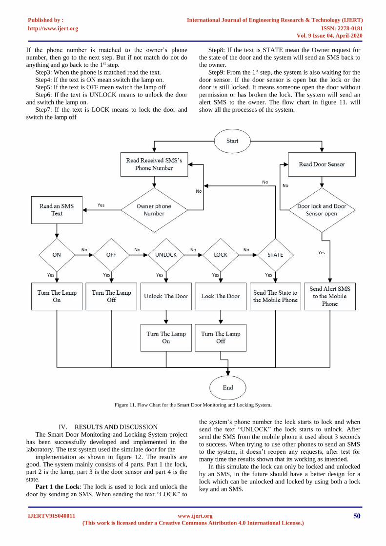
If the phone number is matched to the owner’s phone
number, then go to the next step. But if not match do not do
anything and go back to the 1st step.
Step3: When the phone is matched read the text.
Step4: If the text is ON mean switch the lamp on.
Step5: If the text is OFF mean switch the lamp off
Step6: If the text is UNLOCK means to unlock the door
and switch the lamp on.
Step7: If the text is LOCK means to lock the door and
switch the lamp off
Step8: If the text is STATE mean the Owner request for
the state of the door and the system will send an SMS back to
the owner.
Step9: From the 1st step, the system is also waiting for the
door sensor. If the door sensor is open but the lock or the
door is still locked. It means someone open the door without
permission or has broken the lock. The system will send an
alert SMS to the owner. The flow chart in figure 11. will
show all the processes of the system.
Figure 11. Flow Chart for the Smart Door Monitoring and Locking System.
IV. RESULTS AND DISCUSSION
The Smart Door Monitoring and Locking System project
has been successfully developed and implemented in the
laboratory. The test system used the simulate door for the
implementation as shown in figure 12. The results are
good. The system mainly consists of 4 parts. Part 1 the lock,
part 2 is the lamp, part 3 is the door sensor and part 4 is the
state.
Part 1 the Lock: The lock is used to lock and unlock the
door by sending an SMS. When sending the text “LOCK” to
the system’s phone number the lock starts to lock and when
send the text “UNLOCK” the lock starts to unlock. After
send the SMS from the mobile phone it used about 3 seconds
to success. When trying to use other phones to send an SMS
to the system, it doesn’t reopen any requests, after test for
many time the results shown that its working as intended.
In this simulate the lock can only be locked and unlocked
by an SMS, in the future should have a better design for a
lock which can be unlocked and locked by using both a lock
key and an SMS.
IJERTV9IS040011(This work is licensed under a Creative Commons Attribution 4.0 International License.)
www.ijert.org 50
International Journal of Engineering Research & Technology (IJERT)
ISSN: 2278-0181http://www.ijert.org
Published by :
Vol. 9 Issue 04, April-2020

Part 2 the Lamp: The lamp is used to provide more
function for the user. When the lock is unlocked the lamp will
switch on and when the lock is locked the lamp will switch
off. In the test is sending an SMS text “UNLOCK” to the
system to unlock the lock and after the lock unlocks the
Lamp is switched on. Send an SMS text “LOCK” to the
system to lock the lock after the lock locks the lamp is
switched off.
The lamp also can be switched on and off without the
lock’s evens. Test to send the SMS text “ON” to the system
then then lamp is switched on and send the SMS text “OFF”
to the system then the lamp is switched off.
Figure 12. The complete simulate System of Smart Door Monitoring and
Locking System.
The lamp part can install every kind of lamp such as:
lamp with DC 5v, DC 12v, AC 220v, etc. because the relay
can be use with many kinds of electric.
Part 3 the Door Sensor: The door sensor is used to
detect the door that open or close. This will work with the
door state if the door is lock and the sensor is open. It will
send the alert massage to the owner. Because it means it will
send the alert massage to the owner. Because it means
someone breaks the lock and goes into the house.
In the test, when the system is in the state that the door is
closed or door sensor is closed and the lock is locked, we test
to open the door without unlock it. When the door is opened
the mobile phone received an SMS “Door open without
unlock” as shown in figure 13.
Figure. 13. Mobile phone SMS sent and receive massage.
Part 4 the State: The door open and close, the lamp
switch on and off, the lock locks and unlocks and the
emergency situation. Every even of the system will be saved
to the state in the memory. When the owner requests it, it will
send the state’s status to the owner by an SMS.
In the test. We type a text “STATE” sent to the system and
then after 3 second we receive an SMS “Lamp is on, Door is
Unlock”. This mean the door is unlock and the lamp is still
lighting. But if in the Emergency situation we type a text
“STATE” sent to the system. We will receive an SMS “Lam is
off, door is Emergency”. This mean someone break the door
or the lock.
V. CONCLUSION
The developed system has been tested and implemented by
sending an SMS for unlock the door, look the door, switch on
the lamp, switch off the lamp, test for door sensor and request
for the state from the system. The systems working is good.
The features are like the advanced security system and low
cost and standalone system. Whilst the system is a prototype
the circuit will be developed on PCB using an AVR device for
the microcontroller and replacing the shield with a GSM
module on the PCB. An Arduino UNO and GSM Shield
IJERTV9IS040011(This work is licensed under a Creative Commons Attribution 4.0 International License.)
www.ijert.org 51
International Journal of Engineering Research & Technology (IJERT)
ISSN: 2278-0181http://www.ijert.org
Published by :
Vol. 9 Issue 04, April-2020

would not be used for a production model because the unit
costs of using these components would make a product too
costly. Therefore, redesigning the system onto PCB using
components will reduce the cost of the system to enable
volume production. Future work is planned to develop more
features, complete systems that ready to install in real-life and
can be able to setting or custom.
REFERENCES [1] Mohammed Amenulleh " Microcontroller based programmable digital
door lock security systems by using key pad GSM/CDMA
Technology", IOSR Journal of electrical and Electronics Engineering
(IOSR-JEEE),volume 4 ,issue 6(Mar.-Apr .2013).
[2] Murthy, B. Rama, O. Jagadish, K. Tanveer Alam, V. Mahammad Dada,
and K. Priyanka Gandhi. "Development of GSM Based Advanced Alert
Home Locker Safety Security System Using Arduino UNO." (2018).
[3] Sumalatha, Ch, A. Viyayamanasa, K. Ramasrujana, I. Meghamala, and
K. Lakshmi Prasanna. "Bank Locker Security System Using RFID and
GSM Technology." International Journal for Research in Applied
Science & Engineering Technology 4, no. 4 (2016).
[4] R.Srinivasan, T.Mettilda, D.Surendran, K.Gobinath, P.Sathishkumar,
'ADVANCED LOCKER SECURITY SYSTEM’, International Journal
of Advance Research In Science And Engineering,IJARSE, Vol. No.4,
Special Issue (01), March 2015.Dasd.
[5] Abhishek S. Parab,Amol Joglekar, 'Implementation of Home Security
System using GSM module and Microcontroller’, Abhishek S. Parab et
al, / (IJCSIT) International Journal of Computer Science and
Information Technologies, Vol. 6 (3) , 2015, 2950-2953.
[6] Crystalynne D. Cortez, Jaswinder S. Badwal, Jocelyn R. Hipolito,
Ditche Jane C. Astillero, Melvie S. Dela Cruz, and Jaira C. Inalao,
'Development of Microcontroller-Based Biometric Locker System with
Short Message Service’, Lecture Notes on Software Engineering, Vol.
4, No. 2, May 2016.
[7] Wadhwani, Siddharth, Uday Singh, Prakarsh Singh, and Shraddha
Dwivedi. "Smart home automation and security system using Arduino
and IOT." Int. Res. J. Eng. Technol 5, no. 02 (2018): 1357-1359.
[8] Nasution, Tigor Hamonangan, Muhammad Anggia Muchtar, Ikhsan
Siregar, Ulfi Andayani, Esra Christian, and Emerson Pascawira
Sinulingga. "Electrical appliances control prototype by using GSM
module and Arduino." In 2017 4th International Conference on
Industrial Engineering and Applications (ICIEA), pp. 355-358. IEEE,
2017.
[9] Arduino, Store Arduino. "Arduino." Arduino LLC (2015).
[10] Zaghloul, Mohamed Saad. "GSM-GPRS Arduino Shield (GS-001) with
SIM 900 chip module in wireless data transmission system for data
acquisition and control of power induction furnace." International
Journal of Scientific & Engineering Research 5, no. 4 (2014): 776.
[11] Ohishi, Kiyoshi, Masato Nakao, Kouhei Ohnishi, and Kunio Miyachi.
"Microprocessor-controlled DC motor for load-insensitive position
servo system." IEEE transactions on industrial electronics 1 (1987):
44-49.
IJERTV9IS040011(This work is licensed under a Creative Commons Attribution 4.0 International License.)
www.ijert.org 52
International Journal of Engineering Research & Technology (IJERT)
ISSN: 2278-0181http://www.ijert.org
Published by :
Vol. 9 Issue 04, April-2020