Embed Size (px)
Citation preview
94 ECTI TRANSACTIONS ON COMPUTER AND INFORMATION TECHNOLOGY VOL.8, NO.1 May 2014
Smart Climbing Mirror Cleaning Robot UsingHybrid Fuzzy-PID Control based on
Pneumatic System
Songkran Kantawong1 , Member
ABSTRACT
This paper presents the combination of an intelli-gent fuzzy logic control and robotic technologies fordeveloping an exterior climbing mirror cleaning robotbased on pneumatic system in the advance fields ofhigh building mirror cleaning robot technology. Thetypical pneumatic system is controlled by ON/OFFdirectional valve control that gives usually uncertainresponse both in the terms of position and veloc-ity control and also low accuracy in the moving andholding force control because of its nonlinearity anduncertainty of pneumatic system. The fuzzy logicwith proportional plus derivative plus integral con-trol (fuzzy-PID) presented in this paper will improvethe drawbacks and weak points of the ON/OFF valvecontrol such that it becomes a continuous valve con-trol which enhances the overall performance of thesystem in the same time. The stability of climbingrobot that is moving along any slope angles of mirrorglass surface depends on the holding force, suctioncup parameters and pneumatic piston cylinder con-trol that must be suitably designed and mainly real-ized. More safety factors for high air-pressure supplyin the case of high building include winding force,gravity force and other environmental effects. Theexperimental results show that the fuzzy-PID controlwith pneumatic solenoid and directional valves con-trol gives more satisfactory responses in the terms ofsettling time and steadystate error. The significantimprovement of the position response and nonlinearor dynamic performance of pneumatic piston systemis carried out both in Matlab simulation program andtests at laboratory room. The results are better thanON/OFF valve control and conventional PID control.Finally, the robot can climb very well on any slopeangles of mirror surface that are less than 90 degreewhile the cleaning mechanism can work well as de-sign concept. The future work will further improvethe system performance of climbing robot for moresafety, stability and reliability in the case of verticalslope situation that depends on the wet glass surfaceand more winding force effect.
Manuscript received on March 31, 2013 ; revised on June 26,2013.Final manuscript received March 20, 2014.1 The author is with Department of Electronics and Telecom-
munication Engineering, Faculty of Engineering, Bangkok Uni-versity, Thailand., E-mail: [email protected]
Keywords: Mirror Cleaning Robot, Piston Force,Pneumatic Piston Control, Fuzzy-PID Control, Suc-tion Cup, Suction Force
1. INTRODUCTION
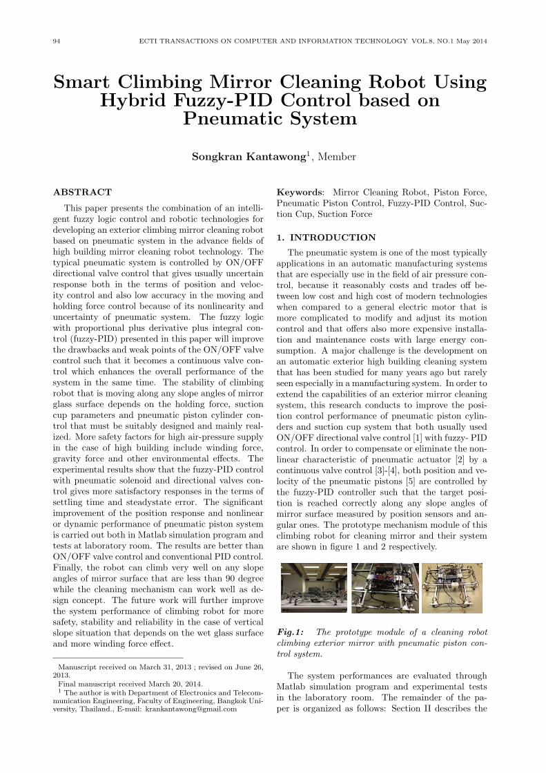
The pneumatic system is one of the most typicallyapplications in an automatic manufacturing systemsthat are especially use in the field of air pressure con-trol, because it reasonably costs and trades off be-tween low cost and high cost of modern technologieswhen compared to a general electric motor that ismore complicated to modify and adjust its motioncontrol and that offers also more expensive installa-tion and maintenance costs with large energy con-sumption. A major challenge is the development onan automatic exterior high building cleaning systemthat has been studied for many years ago but rarelyseen especially in a manufacturing system. In order toextend the capabilities of an exterior mirror cleaningsystem, this research conducts to improve the posi-tion control performance of pneumatic piston cylin-ders and suction cup system that both usually usedON/OFF directional valve control [1] with fuzzy- PIDcontrol. In order to compensate or eliminate the non-linear characteristic of pneumatic actuator [2] by acontinuous valve control [3]-[4], both position and ve-locity of the pneumatic pistons [5] are controlled bythe fuzzy-PID controller such that the target posi-tion is reached correctly along any slope angles ofmirror surface measured by position sensors and an-gular ones. The prototype mechanism module of thisclimbing robot for cleaning mirror and their systemare shown in figure 1 and 2 respectively.
Fig.1: The prototype module of a cleaning robotclimbing exterior mirror with pneumatic piston con-trol system.
The system performances are evaluated throughMatlab simulation program and experimental testsin the laboratory room. The remainder of the pa-per is organized as follows: Section II describes the
Smart Climbing Mirror Cleaning Robot Using Hybrid Fuzzy-PID Control based on Pneumatic System 95
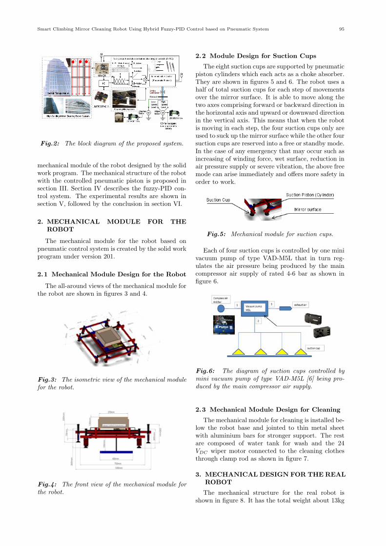
Fig.2: The block diagram of the proposed system.
mechanical module of the robot designed by the solidwork program. The mechanical structure of the robotwith the controlled pneumatic piston is proposed insection III. Section IV describes the fuzzy-PID con-trol system. The experimental results are shown insection V, followed by the conclusion in section VI.
2. MECHANICAL MODULE FOR THEROBOT
The mechanical module for the robot based onpneumatic control system is created by the solid workprogram under version 201.
2.1 Mechanical Module Design for the Robot
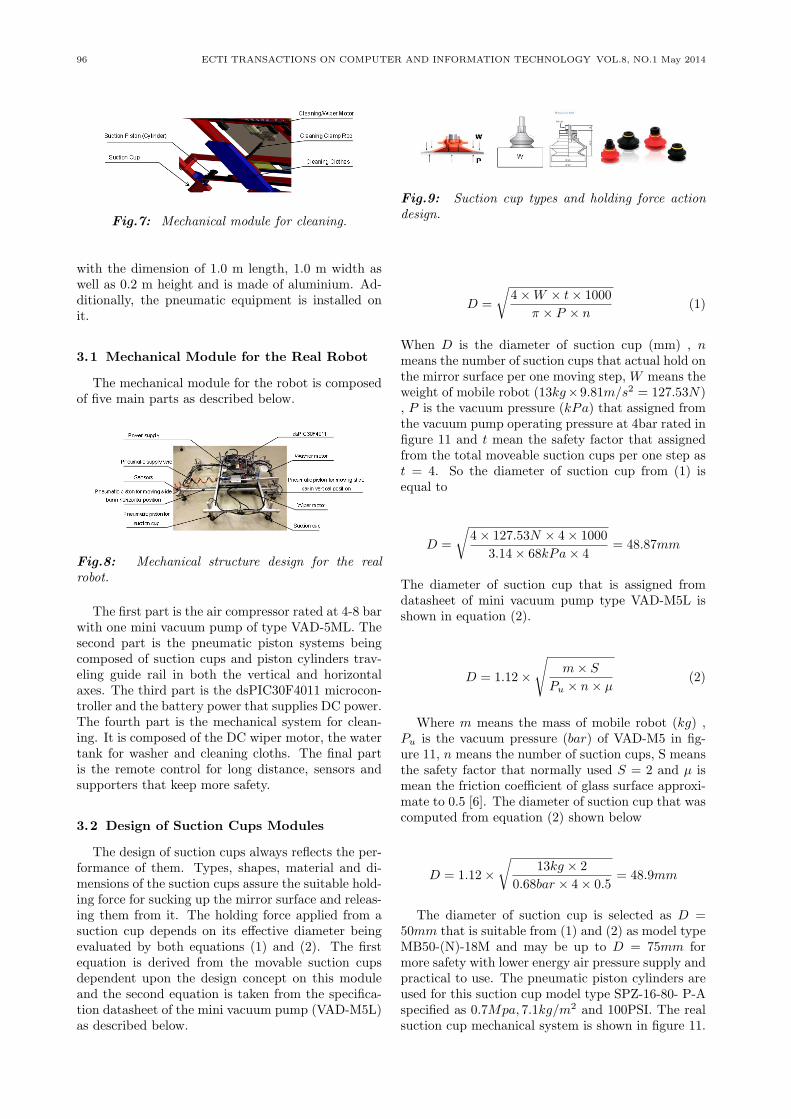
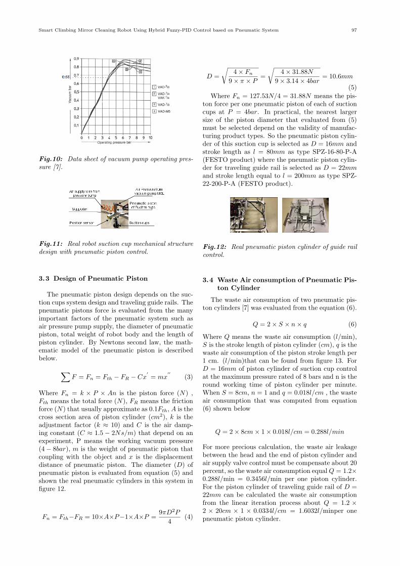
The all-around views of the mechanical module forthe robot are shown in figures 3 and 4.
Fig.3: The isometric view of the mechanical modulefor the robot.
Fig.4: The front view of the mechanical module forthe robot.
2.2 Module Design for Suction Cups
The eight suction cups are supported by pneumaticpiston cylinders which each acts as a choke absorber.They are shown in figures 5 and 6. The robot uses ahalf of total suction cups for each step of movementsover the mirror surface. It is able to move along thetwo axes comprising forward or backward direction inthe horizontal axis and upward or downward directionin the vertical axis. This means that when the robotis moving in each step, the four suction cups only areused to suck up the mirror surface while the other foursuction cups are reserved into a free or standby mode.In the case of any emergency that may occur such asincreasing of winding force, wet surface, reduction inair pressure supply or severe vibration, the above freemode can arise immediately and offers more safety inorder to work.
Fig.5: Mechanical module for suction cups.
Each of four suction cups is controlled by one minivacuum pump of type VAD-M5L that in turn reg-ulates the air pressure being produced by the maincompressor air supply of rated 4-6 bar as shown infigure 6.
Fig.6: The diagram of suction cups controlled bymini vacuum pump of type VAD-M5L [6] being pro-duced by the main compressor air supply.
2.3 Mechanical Module Design for Cleaning
The mechanical module for cleaning is installed be-low the robot base and jointed to thin metal sheetwith aluminium bars for stronger support. The restare composed of water tank for wash and the 24VDC wiper motor connected to the cleaning clothesthrough clamp rod as shown in figure 7.
3. MECHANICAL DESIGN FOR THE REALROBOT
The mechanical structure for the real robot isshown in figure 8. It has the total weight about 13kg
96 ECTI TRANSACTIONS ON COMPUTER AND INFORMATION TECHNOLOGY VOL.8, NO.1 May 2014
Fig.7: Mechanical module for cleaning.
with the dimension of 1.0 m length, 1.0 m width aswell as 0.2 m height and is made of aluminium. Ad-ditionally, the pneumatic equipment is installed onit.
3.1 Mechanical Module for the Real Robot
The mechanical module for the robot is composedof five main parts as described below.
Fig.8: Mechanical structure design for the realrobot.
The first part is the air compressor rated at 4-8 barwith one mini vacuum pump of type VAD-5ML. Thesecond part is the pneumatic piston systems beingcomposed of suction cups and piston cylinders trav-eling guide rail in both the vertical and horizontalaxes. The third part is the dsPIC30F4011 microcon-troller and the battery power that supplies DC power.The fourth part is the mechanical system for clean-ing. It is composed of the DC wiper motor, the watertank for washer and cleaning cloths. The final partis the remote control for long distance, sensors andsupporters that keep more safety.
3.2 Design of Suction Cups Modules
The design of suction cups always reflects the per-formance of them. Types, shapes, material and di-mensions of the suction cups assure the suitable hold-ing force for sucking up the mirror surface and releas-ing them from it. The holding force applied from asuction cup depends on its effective diameter beingevaluated by both equations (1) and (2). The firstequation is derived from the movable suction cupsdependent upon the design concept on this moduleand the second equation is taken from the specifica-tion datasheet of the mini vacuum pump (VAD-M5L)as described below.
Fig.9: Suction cup types and holding force actiondesign.
D =
√4×W × t× 1000
π × P × n(1)
When D is the diameter of suction cup (mm) , nmeans the number of suction cups that actual hold onthe mirror surface per one moving step, W means theweight of mobile robot (13kg×9.81m/s2 = 127.53N), P is the vacuum pressure (kPa) that assigned fromthe vacuum pump operating pressure at 4bar rated infigure 11 and t mean the safety factor that assignedfrom the total moveable suction cups per one step ast = 4. So the diameter of suction cup from (1) isequal to
D =
√4× 127.53N × 4× 1000
3.14× 68kPa× 4= 48.87mm
The diameter of suction cup that is assigned fromdatasheet of mini vacuum pump type VAD-M5L isshown in equation (2).
D = 1.12×
√m× S
Pu × n× µ(2)
Where m means the mass of mobile robot (kg) ,Pu is the vacuum pressure (bar) of VAD-M5 in fig-ure 11, n means the number of suction cups, S meansthe safety factor that normally used S = 2 and µ ismean the friction coefficient of glass surface approxi-mate to 0.5 [6]. The diameter of suction cup that wascomputed from equation (2) shown below
D = 1.12×√
13kg × 2
0.68bar × 4× 0.5= 48.9mm
The diameter of suction cup is selected as D =50mm that is suitable from (1) and (2) as model typeMB50-(N)-18M and may be up to D = 75mm formore safety with lower energy air pressure supply andpractical to use. The pneumatic piston cylinders areused for this suction cup model type SPZ-16-80- P-Aspecified as 0.7Mpa, 7.1kg/m2 and 100PSI. The realsuction cup mechanical system is shown in figure 11.
Smart Climbing Mirror Cleaning Robot Using Hybrid Fuzzy-PID Control based on Pneumatic System 97
Fig.10: Data sheet of vacuum pump operating pres-sure [7].
Fig.11: Real robot suction cup mechanical structuredesign with pneumatic piston control.
3.3 Design of Pneumatic Piston
The pneumatic piston design depends on the suc-tion cups system design and traveling guide rails. Thepneumatic pistons force is evaluated from the manyimportant factors of the pneumatic system such asair pressure pump supply, the diameter of pneumaticpiston, total weight of robot body and the length ofpiston cylinder. By Newtons second law, the math-ematic model of the pneumatic piston is describedbelow. ∑
F = Fn = Fth − FR − Cx′= mx
′′(3)
Where Fn = k × P × An is the piston force (N) ,Fth means the total force (N), FR means the frictionforce (N) that usually approximate as 0.1Fth, A is thecross section area of piston cylinder (cm2), k is theadjustment factor (k ≈ 10) and C is the air damp-ing constant (C ≈ 1.5 − 2Ns/m) that depend on anexperiment, P means the working vacuum pressure(4− 8bar), m is the weight of pneumatic piston thatcoupling with the object and x is the displacementdistance of pneumatic piston. The diameter (D) ofpneumatic piston is evaluated from equation (5) andshown the real pneumatic cylinders in this system infigure 12.
Fn = Fth−FR = 10×A×P−1×A×P =9πD2P
4(4)
D =
√4× Fn
9× π × P=
√4× 31.88N
9× 3.14× 4bar= 10.6mm
(5)
Where Fn = 127.53N/4 = 31.88N means the pis-ton force per one pneumatic piston of each of suctioncups at P = 4bar. In practical, the nearest largersize of the piston diameter that evaluated from (5)must be selected depend on the validity of manufac-turing product types. So the pneumatic piston cylin-der of this suction cup is selected as D = 16mm andstroke length as l = 80mm as type SPZ-16-80-P-A(FESTO product) where the pneumatic piston cylin-der for traveling guide rail is selected as D = 22mmand stroke length equal to l = 200mm as type SPZ-22-200-P-A (FESTO product).
Fig.12: Real pneumatic piston cylinder of guide railcontrol.
3.4 Waste Air consumption of Pneumatic Pis-ton Cylinder
The waste air consumption of two pneumatic pis-ton cylinders [7] was evaluated from the equation (6).
Q = 2× S × n× q (6)
Where Q means the waste air consumption (l/min),S is the stroke length of piston cylinder (cm), q is thewaste air consumption of the piston stroke length per1 cm. (l/min)that can be found from figure 13. ForD = 16mm of piston cylinder of suction cup controlat the maximum pressure rated of 8 bars and n is theround working time of piston cylinder per minute.When S = 8cm, n = 1 and q = 0.018l/cm , the wasteair consumption that was computed from equation(6) shown below
Q = 2× 8cm× 1× 0.018l/cm = 0.288l/min
For more precious calculation, the waste air leakagebetween the head and the end of piston cylinder andair supply valve control must be compensate about 20percent, so the waste air consumption equalQ = 1.2×0.288l/min = 0.3456l/min per one piston cylinder.For the piston cylinder of traveling guide rail of D =22mm can be calculated the waste air consumptionfrom the linear iteration process about Q = 1.2 ×2 × 20cm × 1 × 0.0334l/cm = 1.6032l/minper onepneumatic piston cylinder.
98 ECTI TRANSACTIONS ON COMPUTER AND INFORMATION TECHNOLOGY VOL.8, NO.1 May 2014
Fig.13: Air consumption of piston cylinder stroke[7].
3.5 Waste Air Consumption of Suction CupControl
The volume of air flow that generates the vacuumis important key for the suction force rate. So, thewaste air consumption of suction cups that was con-trolled by mini vacuum pump type VAD-M5 is foundin figure 14. The maximum of operating pressurerated point at 8 bars is equal to 20l/ min of airconsumption rate that can be supply for four suc-tion cups. So, each of suction cups has the maxi-mum air consumption equal to 5l/ min that cover forwaste air consumption of one piston cylinder controlat 0.3456l/ min and allowed by the typical value [7]that the suction rate of suction cup diameter up to60mm is not more that 8.3l/ min .
Fig.14: Air consumption of vacuum pump [7].
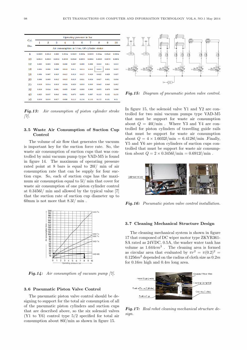
3.6 Pneumatic Piston Valve Control
The pneumatic piston valve control should be de-signing to support for the total air consumption of allof the pneumatic piston cylinders and suction cupsthat are described above, so the six solenoid valves(Y1 to Y6) control type 5/2 specified for total airconsumption about 80l/min as shown in figure 15.
Fig.15: Diagram of pneumatic piston valve control.
In figure 15, the solenoid valve Y1 and Y2 are con-trolled for two mini vacuum pumps type VAD-M5that must be support for waste air consumptionabout Q = 40l/min . Where Y3 and Y4 are con-trolled for piston cylinders of travelling guide railsthat must be support for waste air consumptionabout Q = 4 × 1.6032l/min = 6.4128l/min .Finally,Y5 and Y6 are piston cylinders of suction cups con-trolled that must be support for waste air consump-tion about Q = 2× 0.3456l/min = 0.6912l/min .
Fig.16: Pneumatic piston valve control installation.
3.7 Cleaning Mechanical Structure Design
The cleaning mechanical system is shown in figure17 that composed of DC wiper motor type ZKYR361-SA rated as 24VDC, 0.5A, the washer water tank hasvolume as 1.644cm3 . The cleaning area is formedas circular area that evaluated by πr2 = π(0.2)2 =0.1256m2 depended on the radius of cloth size as 0.2mfor 0.16m high and 0.4m long area.
Fig.17: Real robot cleaning mechanical structure de-sign.
Smart Climbing Mirror Cleaning Robot Using Hybrid Fuzzy-PID Control based on Pneumatic System 99
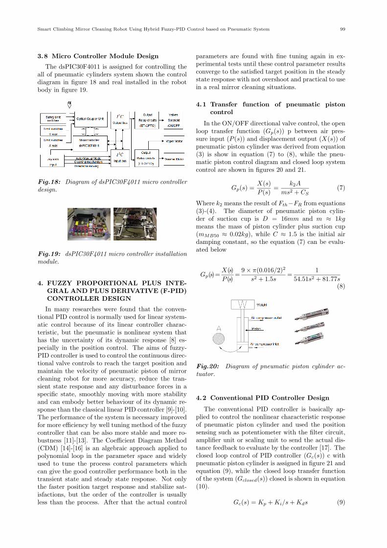
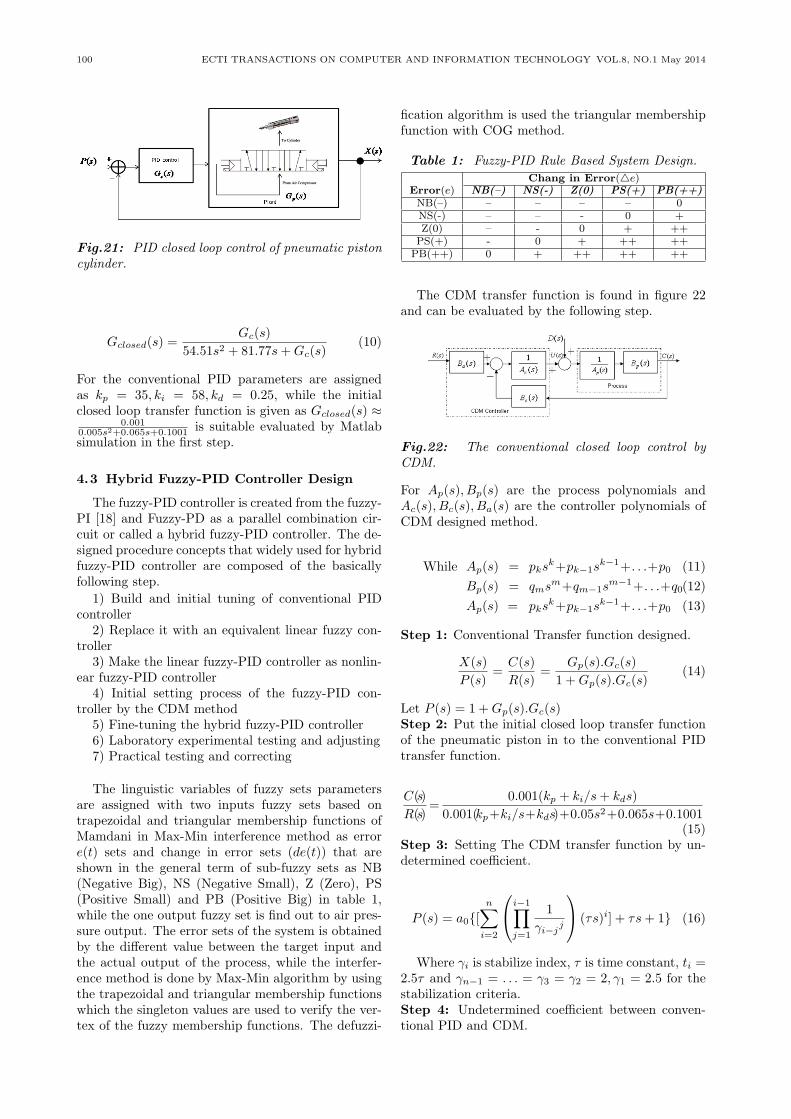
3.8 Micro Controller Module Design
The dsPIC30F4011 is assigned for controlling theall of pneumatic cylinders system shown the controldiagram in figure 18 and real installed in the robotbody in figure 19.
Fig.18: Diagram of dsPIC30F4011 micro controllerdesign.
Fig.19: dsPIC30F4011 micro controller installationmodule.
4. FUZZY PROPORTIONAL PLUS INTE-GRAL AND PLUS DERIVATIVE (F-PID)CONTROLLER DESIGN
In many researches were found that the conven-tional PID control is normally used for linear system-atic control because of its linear controller charac-teristic, but the pneumatic is nonlinear system thathas the uncertainty of its dynamic response [8] es-pecially in the position control. The aims of fuzzy-PID controller is used to control the continuous direc-tional valve controls to reach the target position andmaintain the velocity of pneumatic piston of mirrorcleaning robot for more accuracy, reduce the tran-sient state response and any disturbance forces in aspecific state, smoothly moving with more stabilityand can embody better behaviour of its dynamic re-sponse than the classical linear PID controller [9]-[10].The performance of the system is necessary improvedfor more efficiency by well tuning method of the fuzzycontroller that can be also more stable and more ro-bustness [11]-[13]. The Coefficient Diagram Method(CDM) [14]-[16] is an algebraic approach applied topolynomial loop in the parameter space and widelyused to tune the process control parameters whichcan give the good controller performance both in thetransient state and steady state response. Not onlythe faster position target response and stabilize sat-isfactions, but the order of the controller is usuallyless than the process. After that the actual control
parameters are found with fine tuning again in ex-perimental tests until these control parameter resultsconverge to the satisfied target position in the steadystate response with not overshoot and practical to usein a real mirror cleaning situations.
4.1 Transfer function of pneumatic pistoncontrol
In the ON/OFF directional valve control, the openloop transfer function (Gp(s)) p between air pres-sure input (P (s)) and displacement output (X(s)) ofpneumatic piston cylinder was derived from equation(3) is show in equation (7) to (8), while the pneu-matic piston control diagram and closed loop systemcontrol are shown in figures 20 and 21.
Gp(s) =X(s)
P (s)=
k2A
ms2 + CS(7)
Where k2 means the result of Fth−FR from equations(3)-(4). The diameter of pneumatic piston cylin-der of suction cup is D = 16mm and m ≈ 1kgmeans the mass of piston cylinder plus suction cup(mMB50 ≈ 0.02kg), while C ≈ 1.5 is the initial airdamping constant, so the equation (7) can be evalu-ated below
Gp(s)=X(s)
P (s)=
9× π(0.016/2)2
s2 + 1.5s=
1
54.51s2 + 81.77s(8)
Fig.20: Diagram of pneumatic piston cylinder ac-tuator.
4.2 Conventional PID Controller Design
The conventional PID controller is basically ap-plied to control the nonlinear characteristic responseof pneumatic piston cylinder and used the positionsensing such as potentiometer with the filter circuit,amplifier unit or scaling unit to send the actual dis-tance feedback to evaluate by the controller [17]. Theclosed loop control of PID controller (Gc(s)) c withpneumatic piston cylinder is assigned in figure 21 andequation (9), while the closed loop transfer functionof the system (Gclosed(s)) closed is shown in equation(10).
Gc(s) = Kp +Ki/s+Kds (9)
100 ECTI TRANSACTIONS ON COMPUTER AND INFORMATION TECHNOLOGY VOL.8, NO.1 May 2014
Fig.21: PID closed loop control of pneumatic pistoncylinder.
Gclosed(s) =Gc(s)
54.51s2 + 81.77s+Gc(s)(10)
For the conventional PID parameters are assignedas kp = 35, ki = 58, kd = 0.25, while the initialclosed loop transfer function is given as Gclosed(s) ≈
0.0010.005s2+0.065s+0.1001 is suitable evaluated by Matlabsimulation in the first step.
4.3 Hybrid Fuzzy-PID Controller Design
The fuzzy-PID controller is created from the fuzzy-PI [18] and Fuzzy-PD as a parallel combination cir-cuit or called a hybrid fuzzy-PID controller. The de-signed procedure concepts that widely used for hybridfuzzy-PID controller are composed of the basicallyfollowing step.
1) Build and initial tuning of conventional PIDcontroller
2) Replace it with an equivalent linear fuzzy con-troller
3) Make the linear fuzzy-PID controller as nonlin-ear fuzzy-PID controller
4) Initial setting process of the fuzzy-PID con-troller by the CDM method
5) Fine-tuning the hybrid fuzzy-PID controller6) Laboratory experimental testing and adjusting7) Practical testing and correcting
The linguistic variables of fuzzy sets parametersare assigned with two inputs fuzzy sets based ontrapezoidal and triangular membership functions ofMamdani in Max-Min interference method as errore(t) sets and change in error sets (de(t)) that areshown in the general term of sub-fuzzy sets as NB(Negative Big), NS (Negative Small), Z (Zero), PS(Positive Small) and PB (Positive Big) in table 1,while the one output fuzzy set is find out to air pres-sure output. The error sets of the system is obtainedby the different value between the target input andthe actual output of the process, while the interfer-ence method is done by Max-Min algorithm by usingthe trapezoidal and triangular membership functionswhich the singleton values are used to verify the ver-tex of the fuzzy membership functions. The defuzzi-
fication algorithm is used the triangular membershipfunction with COG method.
Table 1: Fuzzy-PID Rule Based System Design.
Chang in Error(△e)Error(e) NB(–) NS(-) Z(0) PS(+) PB(++)NB(–) – – – – 0NS(-) – – - 0 +Z(0) – - 0 + ++PS(+) - 0 + ++ ++PB(++) 0 + ++ ++ ++
The CDM transfer function is found in figure 22and can be evaluated by the following step.
Fig.22: The conventional closed loop control byCDM.
For Ap(s), Bp(s) are the process polynomials andAc(s), Bc(s), Ba(s) are the controller polynomials ofCDM designed method.
While Ap(s) = pksk+pk−1s
k−1+. . .+p0 (11)
Bp(s) = qmsm+qm−1sm−1+. . .+q0(12)
Ap(s) = pksk+pk−1s
k−1+. . .+p0 (13)
Step 1: Conventional Transfer function designed.
X(s)
P (s)=
C(s)
R(s)=
Gp(s).Gc(s)
1 +Gp(s).Gc(s)(14)
Let P (s) = 1 +Gp(s).Gc(s)Step 2: Put the initial closed loop transfer functionof the pneumatic piston in to the conventional PIDtransfer function.
C(s)
R(s)=
0.001(kp + ki/s+ kds)
0.001(kp+ki/s+kds)+0.05s2+0.065s+0.1001(15)
Step 3: Setting The CDM transfer function by un-determined coefficient.
P (s) = a0{[n∑
i=2
i−1∏j=1
1
γi−jj
(τs)i] + τs+ 1} (16)
Where γi is stabilize index, τ is time constant, ti =2.5τ and γn−1 = . . . = γ3 = γ2 = 2, γ1 = 2.5 for thestabilization criteria.Step 4: Undetermined coefficient between conven-tional PID and CDM.
Smart Climbing Mirror Cleaning Robot Using Hybrid Fuzzy-PID Control based on Pneumatic System 101
P (s) = a0[τ3
γ21 · γ2
.s3 +τ2
γ1.s2 + τs+ 1] (17)
P (s) = 0.00512a0s3 + 0.064a0.s
2 + 0.4a0s+ a0 (18)
Step 5: Find the total parameters such askp, ki, kdTiandTd
s3 : 0.05 = 0.00512a0 → a0 = 0.9765 (19)
s2 : 0.01kd + 0.06 = 0.064a0 → kd = 0.25 (20)
s1 : 0.01kp + 0.1001 = 0.4a0 → kp = 29.0525(21)
s0 : 0.01ki = a0 → ki = 97.65 (22)
Step 6: Fine tuning of fuzzy PID with nonlinear con-trol with trial and error of the following assumptioncriteria that
Quadratic error: I1 =
t∫0
e(t)dt (23)
Normalize overshoot: I2 =y(t)max − r(t)
r(t)(24)
Rise time: I3 min(t/y(t)) = 90%r(t)Setting time:
I4 = min(t/y(t)) ∈ [95%r(t), 105%r(t)] (25)
An equivalent fuzzy-PID controller is designed infigure 23 and the control parameters that are de-rived from the initial setting parameters process byCDM method shown as following kp = 29.0525, ki =97.65, kd = 0.25.
Fig.23: Pneumatic piston control with hybrid fuzzy-PID controller.
After simulation method [19], the fine control pa-rameters have been tested for several system time re-sponses for seeking an optimum values are receivedthat ki = 58, kp = 85, kd = 25 (%PO ≤ 5%) that
used for real testing in the laboratory room.
5. EXPERIMENTAL RESULTS
The performance of the robot system especially inthe fuzzy-PID control is evaluated by the specifica-tion Pentium (R) 4 CPU 3.01 GHz with Matlab sim-ulation program and Solid work simulation programversion 2010. The real robot mechanisms are provedby mathematical analysis and real experimental testswere done in the laboratory room.
Table 2: Comparing results of conventional PIDand Fuzzy-PID control.
No.Components
Descriptions Type Rated
1
Main air pressure pump supply,
PUMA 4-8bar220VAC, 3 horse power, 2.2kW, 2,850 rpm, air flow rate as250 litre/minute, air pressure as10kg/150 psi
2
Vacuum pump mini with
VAD-M5L 55psiconnection plate A, D = 6mm,Maximum vaccumn = 81kPa or101.5psi, feed pressure as 0.38-0.6Mpa
3Pneumatic piston cylinder of
SPZ-16- 50-500suction cup as D = 16mm,
80-P-A mm/secstroke length as 80mm
4
Pneumatic piston cylinder oftraveling guide rail as SPZ-22- 50-500D = 22mm, stroke length as 200-P-A mm/sec200mm
5Suction cup (vacuum pad) MB50-(N)- > 6.5diameter as D = 50mm 18M kg/cup
6Diameter of air pressure valve
Solenoid 0-0.9with variable speed control
valve kg/cm2regulator D = 6mm
7DC Wiper motor as 24VDC, ZKYR361-
100rpm0.5A SA
8 Cleaning Water TankWindshield
1, 664cm3washer
9 Micro controller controldSPIC30F
12C BUS4011
Table 3: Comparing results of conventional PIDand Fuzzy-PID control.
Robot Operation Conventional Hybrid-fuzzy PID(Rated speed) PID (Present)
Rise time (s) 0.5 ≤ 0.05
Setting time (s) 1.0 ≤ 0.1
Steady state error (mm) 0.1-0.2 0
Suction cups time (s) 0.5-1.0 ≤ 0.5
Average climbing speed (m/s) 0.150 0.135
Average cleaning speed (rpm) 93.2 95.2
Wipe cleaning area (m2) 0.1256 0.1256
Fig.24: The simulation result of fuzzy-PID con-trolled with pneumatic piston (Step response simula-tion with Matlab).
The simulation result in figure 24 which plots be-tween time (sec) and amplitude (unit step) responsein horizontal and vertical axes respectively revealsthat the fuzzy- PID control is given superior accu-racy response than the conventional PID control both
102 ECTI TRANSACTIONS ON COMPUTER AND INFORMATION TECHNOLOGY VOL.8, NO.1 May 2014
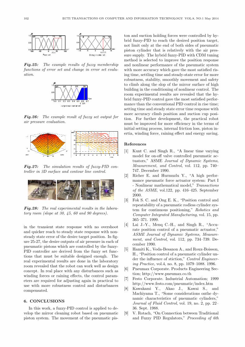
Fig.25: The example results of fuzzy membershipfunctions of error set and change in error set evalu-ation.
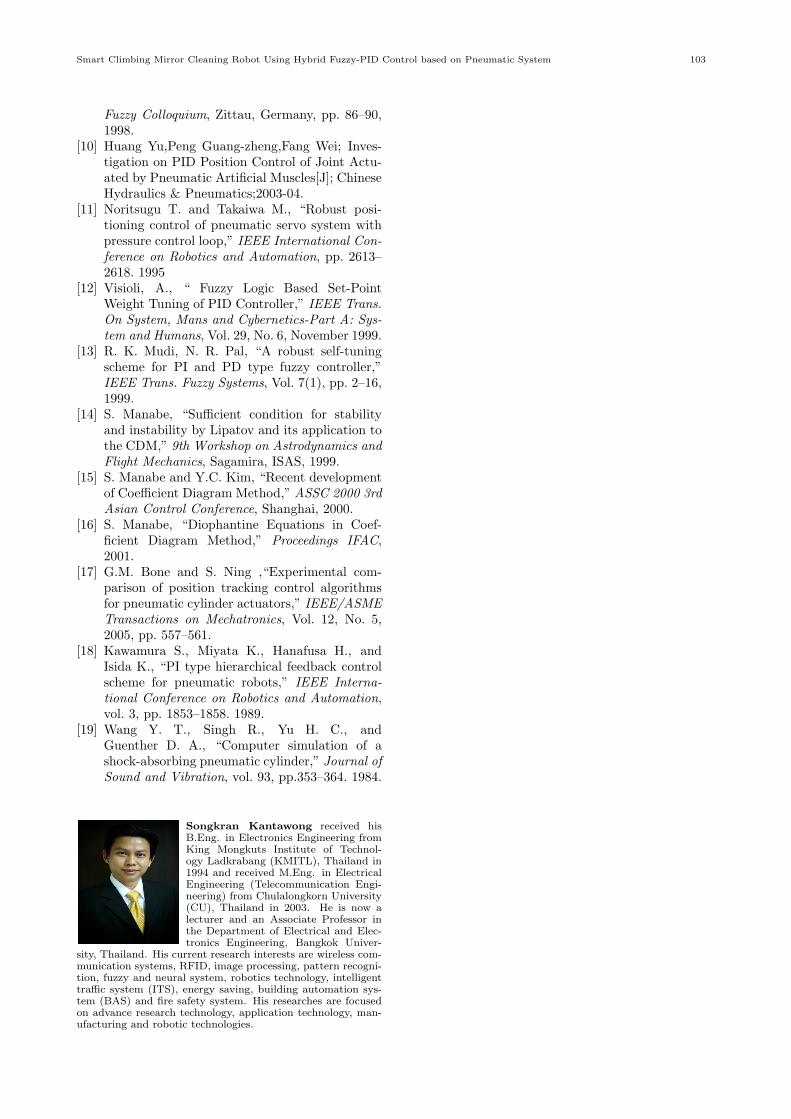
Fig.26: The example result of fuzzy set output forair pressure evaluation.
Fig.27: The simulation results of fuzzy-PID con-troller in 3D surface and contour line control.
Fig.28: The real experimental results in the labora-tory room (slope at 30, 45, 60 and 90 degrees).
in the transient state response with no overshootand quicker reach to steady state response with non-steady state error of the desire target position. In fig-ure 25-27, the desire outputs of air pressure in each ofpneumatic pistons which are controlled by the fuzzy-PID controller are derived from the fuzzy set func-tions that must be suitable designed enough. Thereal experimental results are done in the laboratoryroom revealed that the robot can work well as designconcept. In real place with any disturbances such aswinding forces or raining effects, the control param-eters are required for adjusting again in practical touse with more robustness control and disturbancescompensated.
6. CONCLUSIONS
In this work, a fuzzy-PID control is applied to de-velop the mirror cleaning robot based on pneumaticpiston system. The movement of the pneumatic pis-
ton and suction holding forces were controlled by hy-brid fuzzy-PID to reach the desired position target,not limit only at the end of both sides of pneumaticpiston cylinder that is relatively with the air pres-sure supply. The hybrid fuzzy-PID with CDM tuningmethod is selected to improve the position responseand nonlinear performance of the pneumatic systemwith more accuracy which gave the most satisfied ris-ing time, settling time and steady-state error for morerobustness, stability, smoothly movement and safetyto climb along the slop of the mirror surface of highbuilding in the conditioning of nonlinear control. Theroom experimental results are revealed that the hy-brid fuzzy-PID control gave the most satisfied perfor-mance than the conventional PID control in rise time;setting time and steady state error time response withmore accuracy climb position and suction cup posi-tion. For further development, the practical robotmust be improved for more efficiency in the terms ofinitial setting process, internal friction loss, piston in-ertia, winding force, raining effect and energy saving.
References
[1] Kunt C. and Singh R., “A linear time varyingmodel for on-off valve controlled pneumatic ac-tuators,” ASME Journal of Dynamic Systems,Measurement, and Control, vol. 112, pp. 740–747. December 1990.
[2] Richer E. and Hurmuzlu Y., “A high perfor-mance pneumatic force actuator system: Part I- Nonlinear mathematical model,” Transactionsof the ASME, vol.122, pp. 416–425. September2000.
[3] Fok S. C. and Ong E. K., “Position control andrepeatability of a pneumatic rodless cylinder sys-tem for continuous positioning,” Robotics andComputer Integrated Manufacturing, vol. 15, pp.365–371. 1999.
[4] Lai J.-Y., Menq C.-H., and Singh R., “Accu-rate position control of a pneumatic actuator,”ASME Journal of Dynamic Systems, Measure-ment, and Control, vol. 112, pp. 734–739. De-cember 1990.
[5] Hamiti K., Voda-Besanon A., and Roux-Boisson,H., “Position control of a pneumatic cylinder un-der the influence of stiction,” Control Engineer-ing Practice, vol.4, no. 8, pp. 1079–1088. 1996.
[6] Pneumax Corporate. Products Engineering Sec-tion; http://www.pneumax.co.th
[7] Festo Corporate. Industrial Automation; 1999http://www.festo.com/pneumatic/index.htm
[8] Kawakami Y., Akao J., Kawai S., andMachiyama T., “Some considerations onthe dy-namic characteristics of pneumatic cylinders,”Journal of Fluid Control, vol. 19, no. 2, pp. 22–36. Sept. 1988.
[9] V. Rotach, “On Connection between Traditionaland Fuzzy PID Regulators,” Proceeding of 6th
Smart Climbing Mirror Cleaning Robot Using Hybrid Fuzzy-PID Control based on Pneumatic System 103
Fuzzy Colloquium, Zittau, Germany, pp. 86–90,1998.
[10] Huang Yu,Peng Guang-zheng,Fang Wei; Inves-tigation on PID Position Control of Joint Actu-ated by Pneumatic Artificial Muscles[J]; ChineseHydraulics & Pneumatics;2003-04.
[11] Noritsugu T. and Takaiwa M., “Robust posi-tioning control of pneumatic servo system withpressure control loop,” IEEE International Con-ference on Robotics and Automation, pp. 2613–2618. 1995
[12] Visioli, A., “ Fuzzy Logic Based Set-PointWeight Tuning of PID Controller,” IEEE Trans.On System, Mans and Cybernetics-Part A: Sys-tem and Humans, Vol. 29, No. 6, November 1999.
[13] R. K. Mudi, N. R. Pal, “A robust self-tuningscheme for PI and PD type fuzzy controller,”IEEE Trans. Fuzzy Systems, Vol. 7(1), pp. 2–16,1999.
[14] S. Manabe, “Sufficient condition for stabilityand instability by Lipatov and its application tothe CDM,” 9th Workshop on Astrodynamics andFlight Mechanics, Sagamira, ISAS, 1999.
[15] S. Manabe and Y.C. Kim, “Recent developmentof Coefficient Diagram Method,” ASSC 2000 3rdAsian Control Conference, Shanghai, 2000.
[16] S. Manabe, “Diophantine Equations in Coef-ficient Diagram Method,” Proceedings IFAC,2001.
[17] G.M. Bone and S. Ning ,“Experimental com-parison of position tracking control algorithmsfor pneumatic cylinder actuators,” IEEE/ASMETransactions on Mechatronics, Vol. 12, No. 5,2005, pp. 557–561.
[18] Kawamura S., Miyata K., Hanafusa H., andIsida K., “PI type hierarchical feedback controlscheme for pneumatic robots,” IEEE Interna-tional Conference on Robotics and Automation,vol. 3, pp. 1853–1858. 1989.
[19] Wang Y. T., Singh R., Yu H. C., andGuenther D. A., “Computer simulation of ashock-absorbing pneumatic cylinder,” Journal ofSound and Vibration, vol. 93, pp.353–364. 1984.
Songkran Kantawong received hisB.Eng. in Electronics Engineering fromKing Mongkuts Institute of Technol-ogy Ladkrabang (KMITL), Thailand in1994 and received M.Eng. in ElectricalEngineering (Telecommunication Engi-neering) from Chulalongkorn University(CU), Thailand in 2003. He is now alecturer and an Associate Professor inthe Department of Electrical and Elec-tronics Engineering, Bangkok Univer-
sity, Thailand. His current research interests are wireless com-munication systems, RFID, image processing, pattern recogni-tion, fuzzy and neural system, robotics technology, intelligenttraffic system (ITS), energy saving, building automation sys-tem (BAS) and fire safety system. His researches are focusedon advance research technology, application technology, man-ufacturing and robotic technologies.


![Design and Implementation of an Autonomous Climbing Robot [1]ai.stanford.edu/~rxzhang/Capuchin Climbing Robot.pdf · Control of A Climbing Robot Using Real-time Convex Optimization](https://img.pdfslide.us/doc/110x75/5e53900385cc1170eb34bd01/design-and-implementation-of-an-autonomous-climbing-robot-1ai-rxzhangcapuchin.jpg)