Embed Size (px)
Citation preview

SMART Board™ 685ix Premium Interactive Whiteboard SystemInstallation on the FUWM-600 Fixed Unit Wall Mount

Product registration
If you register your SMART product, we’ll notify you of new features and
software upgrades.
Register online at www.smarttech.com/us/Product+Registration.
Keep the following information available in case you need to contact
SMART Technical Support.
Serial number: ___________________________________________________
Date of purchase: ___________________________________________________
FCC warningThis equipment has been tested and found to comply with the limits for a Class A digital device, pursuant to Part 15 of the FCC Rules. These limits are designed to provide reasonable protection against harmful interference when the equipment is operated in a commercial environment. This equipment generates, uses and can radiate radio frequency energy and, if not installed and used in accordance with the manufacturer’s instructions, may cause harmful interference to radio communications. Operation of this equipment in a residential area is likely to cause harmful interference in which case the user will be required to correct the interference at his own expense.
Trademark noticeSMART Board, SMART Meeting Pro, the SMART logo and smarttech are trademarks or registered trademarks of SMART Technologies ULC in the U.S. and/or other countries. Phillips is a registered trademark of Phillips Screw Company. All other third-party product and company names may be trademarks of their respective owners.
Copyright notice©2010 SMART Technologies ULC. All rights reserved. No part of this publication may be reproduced, transmitted, transcribed, stored in a retrieval system or translated into any language in any form by any means without the prior written consent of SMART Technologies ULC. Information in this manual is subject to change without notice and does not represent a commitment on the part of SMART.
Portions of the software that ships with this product are copyrighted by Intel Corporation.
Portions of the software that ships with this product are copyrighted by ParaGraph, a business unit of Vadem.
Patent No. US5448263; US6141000; US6320597; US6326954; US6337681; US6540366; US6741267, US6747636; US7151533; US7289113; US7499033; US7626577; US7687736; CA2058219; and CA2252302. Other patents pending.

Important information
Before you install and use your SMART Board™ 685ix Premium interactive
whiteboard system, read and understand the safety warnings and cautions in this
user’s guide. This information describes the safe and correct operation of your
SMART Board interactive whiteboard and its accessories and helps prevent injuries
and equipment damage.
If you own a SMART product other than a SMART Board 685ix Premium interactive
whiteboard system, refer to the installation manual for your product for relevant
warnings and maintenance instructions.
NOTE
In this document, the term “interactive whiteboard” refers to your interactive
whiteboard and its accessories and options.
Safety warnings and cautions
WARNINGS
• Failure to follow the installation instructions included with your interactive
whiteboard, or found in this guide, could result in personal injury or product
damage.
• Two people are required to safely mount your interactive whiteboard on a wall
mount because it could be too heavy for one person to safely maneuver.
When you lift your interactive whiteboard, you and your assistant should stand
on either side of the screen, supporting its weight at the bottom corners while
balancing the top with your other hands.
• Do not leave cables on the floor where they can be a tripping hazard. If you
must run a cable over the floor, lay it in a flat, straight line and secure it to the
floor with tape or a cable management strip of a contrasting color. Handle
cables carefully and avoid excessive bending.
• To reduce the risk of fire or electric shock, do not expose your SMART Board
interactive whiteboard to rain or moisture.
• There are no user-serviceable parts inside the pen tray. Only qualified
personnel should disassemble the pen tray’s printed circuit boards, and this
procedure must be done with proper electrostatic discharge (ESD) protection.

i i | IMPORTANT INFORMATION
CAUTIONS
• If you need to lean your interactive whiteboard against a wall before you
mount it, make sure that it remains in an upright position, resting on its pen
tray brackets, which are designed to sustain your interactive whiteboard’s
weight.
• Do not rest your interactive whiteboard on its side or on the top of its frame.
• Do not add any extra weight or excessive pressure to a wall-mounted
interactive whiteboard or its pen tray. SMART designed the brackets
to support only the weight of your interactive whiteboard during normal use.
• For operating safety and to avoid damage to your interactive whiteboard,
connect its USB connector only to a computer that has a USB compliant
interface and that bears the USB logo. In addition, the USB source computer
must be compliant with CSA/UL/EN 60950 and bear the CE mark and CSA
and/or UL mark(s) for CSA/UL 60950.
Other precautionsTo ensure operating safety and to prevent product damage, observe the following
precautions.
• Don’t set up or use your interactive whiteboard in an area with excessive levels of
dust, humidity or smoke.
• If your SMART Board interactive whiteboard requires replacement parts,
make sure that the service technician uses replacement parts specified by
SMART Technologies or parts with the same characteristics as the original.
• Be aware that security cable locks aren’t designed to be a solid protection
measure because the lock can be torn out. However, potential thieves might be
reluctant to try to sell a product with a broken security cable lock hole, which
would readily identify it as a stolen item.

Contents
Important information ..............................................................................................i
Safety warnings and cautions...........................................................................i
Other precautions......................................................................................ii
Installing your SMART Board 685ix Premium interactive whiteboard system ...... 1
In this chapter ................................................................................................. 1
Before installing the SMART Board 685ix interactive whiteboard system ...... 2
Environmental requirements .................................................................... 2
Verify the installation of the FUWM-600 wall mount and the computer.... 2
Mounting your SMART Board 685ix interactive whiteboard system on a
FUWM-600 ..................................................................................................... 3
Important .................................................................................................. 3
Tools required .......................................................................................... 3
Installing the projector mount and wall mount bracket ............................. 4
Installing the ECP on the interactive whiteboard’s frame......................... 6
Installing the ECP and projector cables and the guest
computer harness .................................................................................... 6
Installing the computer cables.................................................................. 8
Installing SBA speakers and cables......................................................... 9
Installing additional cables ..................................................................... 10
Installing the UX60 projector .................................................................. 10
Securing the cables................................................................................ 12
Mounting the interactive whiteboard....................................................... 12
Completing your installation.......................................................................... 13
Aligning your interactive whiteboard with the projector .......................... 13
Attaching the ECP module ..................................................................... 13
Installing the pen tray ............................................................................. 14

iv | CONTENTS
Mounting the guest computer harness................................................... 14
Orienting your interactive whiteboard ........................................................... 16
Setting orientation precision................................................................... 16
Orienting the interactive whiteboard system .......................................... 17
Hardware environmental compliance.................................................................. 19
Waste Electrical and Electronic Equipment regulations (WEEE directive) ... 19
Restriction of Certain Hazardous Substances (RoHS directive)................... 19
Packaging ..................................................................................................... 19
China’s Electronic Information Products regulations .................................... 20
U.S. Consumer Product Safety Improvement Act ........................................ 20
Customer support................................................................................................ 21
Online information and support..................................................................... 21
Training......................................................................................................... 21
Technical support ......................................................................................... 21
Shipping and repair status ............................................................................ 21
General inquiries........................................................................................... 22
Warranty ....................................................................................................... 22
Registration................................................................................................... 22

Chapter 1
Installing your SMART Board 685ix Premium interactive whiteboard system
IMPORTANT
• Use the instructions in this guide to install your SMART Board 685 interactive
whiteboard, UX60 projector and extended control panel (ECP) on the fixed
unit wall mount 600 (FUWM-600).
• The instructions in your SMART Board 685 interactive whiteboard box do not
include instructions for installing the UX60 projector or ECP, and the
instructions in the SMART Board 685ix and SBD685 Interactive Whiteboard
System document do not show how to mount the interactive whiteboard or
projector on the wall mount.
• Refer to the FUWM-600 Computer installation instructions included with the
wall mount, document 99-01035-20, to install the wall mount.
In this chapterRefer to these topics for information about mounting your SMART Board 685ix
interactive whiteboard system on the FUWM-600.
• Before installing the SMART Board 685ix interactive whiteboard system on
page 2
– Environmental requirements on page 2
– Verify the installation of the FUWM-600 wall mount and the computer on
page 2
• Mounting your SMART Board 685ix interactive whiteboard system on a
FUWM-600 on page 3
– Tools required on page 3
– Installing the projector mount and wall mount bracket on page 4
– Installing the ECP on the interactive whiteboard’s frame on page 6

2 | INSTALLING YOUR SMART BOARD 685IX PREMIUM INTERACTIVE WHITEBOARD SYSTEM
– Installing the ECP and projector cables and the guest computer harness on
page 6
– Installing the computer cables on page 8
– Installing SBA speakers and cables on page 9
– Installing additional cables on page 10
– Installing the UX60 projector on page 10
– Mounting the interactive whiteboard on page 12
• Completing your installation on page 13
– Aligning your interactive whiteboard with the projector on page 13
– Attaching the ECP module on page 13
– Installing the pen tray on page 14
– Mounting the guest computer harness on page 14
• Orienting your interactive whiteboard on page 16
– Setting orientation precision on page 16
– Orienting the interactive whiteboard system on page 17
Before installing the SMART Board 685ix interactive whiteboard system
Environmental requirementsBefore installing your system, refer to the environmental requirements in the SMART
Board™ 685ix Interactive Whiteboard System Configuration and User’s Guide,
document 99-00984-20, provided with your system.
Verify the installation of the FUWM-600 wall mount and the computerYou must complete the installation of the FUWM-600 wall mount and the computer
before you can install the UX60 projector, the SMART Board 658 interactive
whiteboard and the ECP. Refer to the FUWM-600 Computer installation guide,
document 99-01035-20, provided with your FUWM-600 unit for more information.

3 | INSTALLING YOUR SMART BOARD 685IX PREMIUM INTERACTIVE WHITEBOARD SYSTEM
Mounting your SMART Board 685ix interactive whiteboard system on a FUWM-600
ImportantBefore mounting your interactive whiteboard system on the FUWM-600, carefully read
and observe the following instructions to ensure operating safety and to prevent
damage to your product.
WARNINGS
• Failure to follow these instructions could result in personal injury and product
damage
• Two people are required to safely mount your projector and interactive
whiteboard on the wall mount because they could be too heavy for one
person to safely maneuver. When you lift your interactive whiteboard, you and
your assistant should stand on either side of the screen, supporting its weight
at the bottom corners while balancing the top with your other hands.
• Do not leave cables on the floor where they can be a tripping hazard. If you
must run a cable over the floor, lay it in a flat, straight line and secure it to the
floor with tape or a cable management strip of a contrasting color. Handle
cables carefully and avoid excessive bending.
Tools requiredTo mount your interactive whiteboard on the FUWM-600 wall mount, you need the
following tools, which aren’t included with your interactive whiteboard system:
• a Phillips® No. 2 screwdriver (all screws must be tightened by hand)
• an electric drill with a 1/8" (3 mm) and a 1/4" (6 mm) drill bit
• a measuring tape
• a pencil
• a stepladder
×2
#2
1/8" (3 mm) and
1/4" (6 mm)
No. 2
×2

4 | INSTALLING YOUR SMART BOARD 685IX PREMIUM INTERACTIVE WHITEBOARD SYSTEM
CAUTION
• If you need to lean your interactive whiteboard against a wall before you
mount it, make sure that it remains in an upright position, resting on its pen
tray brackets, which are designed to sustain your interactive whiteboard’s
weight.
• Do not rest your interactive whiteboard on its side or on the top of its frame.
Installing the projector mount and wall mount bracketTo install the projector mount, use the screws labeled f (×7) shown on page 27 of the
FUWM-600 Computer installation guide.
To install the projector
mount
1. Using a Phillips No. 2 screwdriver, insert four screws into the four top-right holes
of the projector support leaving the screw heads 1/4" (6 mm) from its surface.
2. Place the projector mounting plate keyholes over the screws, and then tighten
the screws.
Projector Mounting
Plate
Screws (×4)Keyholes (×4)
Projector Support
5 | INSTALLING YOUR SMART BOARD 685IX PREMIUM INTERACTIVE WHITEBOARD SYSTEM
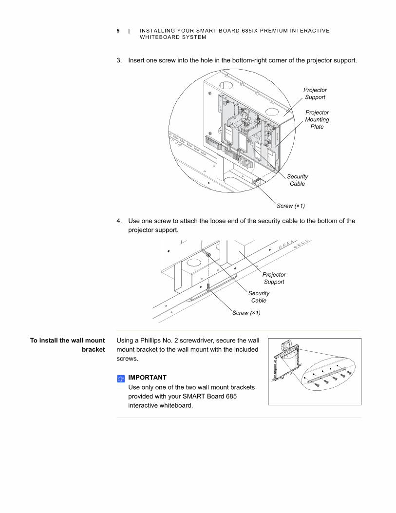
3. Insert one screw into the hole in the bottom-right corner of the projector support.
4. Use one screw to attach the loose end of the security cable to the bottom of the
projector support.
To install the wall mount
bracket
Using a Phillips No. 2 screwdriver, secure the wall
mount bracket to the wall mount with the included
screws.
IMPORTANT
Use only one of the two wall mount brackets
provided with your SMART Board 685
interactive whiteboard.
Screw (×1)
Projector Mounting
Plate
Security Cable
Projector Support
Security Cable
Screw (×1)
Projector Support

6 | INSTALLING YOUR SMART BOARD 685IX PREMIUM INTERACTIVE WHITEBOARD SYSTEM
Installing the ECP on the interactive whiteboard’s frameBefore you install the interactive whiteboard, temporarily attach the ECP to the
lower-right of the frame using self-tapping screws. Later in the installation, you’ll
permanently attach the ECP after connecting all of its cables.
To install the ECP 1. Lay the interactive whiteboard on its back on a
flat surface.
2. Position the ECP module on the bottom frame
4 1/2" (11.4 cm) from the inside edge of the right
frame.
3. Using the ECP as a template, drill two 1/8" holes
in the bottom frame.
4. Using a Phillips No. 2 screwdriver, attach the
ECP to the frame with two included self-tapping
screws.
5. Remove those two screws and the ECP. Put the
screws in a safe location and keep the ECP
nearby to use in a later procedure.
IMPORTANT
You must remove the ECP so you can connect cables to it before you
permanently attach it to the interactive whiteboard’s frame.
6. Place the interactive whiteboard in a safe location until later in the installation.
Installing the ECP and projector cables and the guest computer harnessBecause the ECP cables, projector cables and guest computer harness are installed
inside the wall mount frame, behind the interactive whiteboard, you must install them
now.
To install the cables to the
projector cable support
1. Position the five-connector end of the ECP
cable and the two-connector end of the guest
computer harness on the right end of the wire
management clip, and then push them into their
slots in clip.
2. Place the female end of the power cable to the
left of the cable clips leaving enough length to
connect to the projector’s power connector.
4 1/2" (11.4 cm)

7 | INSTALLING YOUR SMART BOARD 685IX PREMIUM INTERACTIVE WHITEBOARD SYSTEM
3. Close the wire management clip.
4. Route the ECP cable through the opening in the lower right of the bottom frame of
the wall mount, and then connect it to the ECP.
5. Route the USB cable of the guest computer harness through the opening in the
lower right of the bottom frame of the wall mount, and then connect it to the ECP.
6. Route the guest computer harness through the opening in the right side of the
wall mount.
7. Route the projector’s power cable through an opening in the bottom or side of the
wall mount closest to your wall outlet.
NOTE
Don’t connect the power cable to a wall outlet at this time.
ECP Cable
ECP
Guest Computer Harness
Power Cable
USB Cable

8 | INSTALLING YOUR SMART BOARD 685IX PREMIUM INTERACTIVE WHITEBOARD SYSTEM
Installing the computer cablesYou’re unable to access the computer’s rear connection panel after you install the
interactive whiteboard, so you must connect the computer cables now.
To install the computer
cables
1. Connect the audio, video, USB and power cables to the computer’s rear
connection panel.
2. Route the power cable through an opening in the bottom or side of the wall mount
closest to your wall outlet.
3. Route the USB cable through the opening in the lower right of the bottom frame of
the wall mount, and then connect it to the ECP’s captive USB connector.
4. Route the audio and video cables up to the projector’s wire management clip, and
then open the clip.
5. While holding the projector’s power cable in place, place the audio and video
cables beside the power cable, leaving enough length to connect them to the
projector’s connectors.
NOTE
Don’t let the cables cross as they pass through the clip.
6. Close the wire management clip.
USB Cable
Computer Audio, Video,
USB and Power Cables
Computer
ECP
Audio and Video Cables

9 | INSTALLING YOUR SMART BOARD 685IX PREMIUM INTERACTIVE WHITEBOARD SYSTEM
Installing SBA speakers and cablesSMART recommends that you install your SMART Board Audio (SBA) speakers on
the wall on each side of the interactive whiteboard instead of attaching them to the
interactive whiteboard.
NOTES
• You can install the speakers now or after you’ve installed the interactive
whiteboard.
• The following procedures show the main speaker mounted to the right of the
interactive whiteboard, which maintains the correct left to right stereo image. If
control module accessibility or proximity to a power outlet requires it, you can
mount the main speaker on the left and change the routing of the speaker
cables accordingly.
To install the SBA
speakers and cables
1. Refer to the SBA Speakers for SMART Board Interactive Whiteboards installation
guide provided with the speakers to install them.
2. Route the 1/8" (3.5 mm) phone plug end of the phone-to-dual-RCA audio cable
(included with the FUWM-600) up to the projector’s wire management clip, and
then open the clip.
3. While holding the other cables in place, place the audio cable beside them,
leaving enough length to connect to the projector’s phone jack.
NOTE
Don’t let the cables cross as they pass through the clip.
Main Speaker
Dual RCA Plugs
Speaker CableProjector
Audio Cable
Phone Plug
Computer USB Cable
Second Speaker

10 | INSTALLING YOUR SMART BOARD 685IX PREMIUM INTERACTIVE WHITEBOARD SYSTEM
4. Close the wire management clip.
5. Connect the other end of the audio cable from the projector mount to the main
speaker.
6. Route the speaker cable from the main speaker to the second speaker through
the oval openings in the top right and top left of the wall mount, and then connect
it to both speakers.
7. Optionally, you can connect a USB cable from the computer to the main speaker.
NOTE
If you connect a USB cable directly from the computer to the speaker, you
can’t control the audio volume with the projector’s remote control.
8. Coil up and secure any excess cable inside the wall mount frame.
Installing additional cablesIf you wish to connect your interactive whiteboard system to a network, a room control
system or other peripheral audio-visual devices, connect them now using the
techniques outlined in the previous procedures. Ensure that all cables are routed
through openings in the sides or bottom of the wall mount frame.
Installing the UX60 projector
WARNING
Two people are required to safely mount your UX60 projector on the wall mount
because it could be too heavy for one person to safely maneuver.
To install the UX60
projector
1. With the help of another person, fully insert the
projector adjustment module into the wall
mount bracket guide pins.
You hear a click when the adjustment module is
fully inserted and the spring is locked.

11 | INSTALLING YOUR SMART BOARD 685IX PREMIUM INTERACTIVE WHITEBOARD SYSTEM
2. Using a Phillips No. 2 screwdriver, safely
secure the system using three locking screws.
3. Remove the cover from the left side of the
projector.
4. Connect the five ECP cable connectors, the two guest computer harness
connectors and the power cable to the projector connection panel.
5. Connect the computer’s video and audio cable to the VGA 1 inputs.
6. Connect the SBA speaker audio cable to the Audio Out connector, and then
connect any other optional cables.
7. Replace the cover.
Locking Screws
(× 3)
VGA 2
Audio In
Composite Video
ECP
DC 5V 2A
100V - 240V50 Hz - 60 Hz

12 | INSTALLING YOUR SMART BOARD 685IX PREMIUM INTERACTIVE WHITEBOARD SYSTEM
Securing the cablesBefore you mount the interactive whiteboard on the wall mount, secure the cables to
prevent strain on connectors and to keep excessively long cables hidden behind the
interactive whiteboard.
To secure the cables Using the included cable ties, secure all the cables to points inside the wall mount
frame, ensuring that they don’t interfere with the interactive whiteboard when it’s
mounted on the frame.
Mounting the interactive whiteboardFollow this procedure to mount your SMART Board 685 interactive whiteboard on the
FUWM-600.
To mount your
interactive whiteboard
1. Attach the round spacers to the back of the
interactive whiteboard.
NOTE
The round spacers are provided with the
FUWM-600.
2. Verify that no cables or hardware that can
interfere with the wall mount are attached to the
back of the interactive whiteboard.
3. With the help of another person, hang your
interactive whiteboard on the wall mount near the center of the bracket.
4. Using a Phillips No. 2 screwdriver, insert a bolt through the left pen tray bracket
into the left captive nut in the wall mount. Repeat with the right pen tray bracket.
NOTE
Don’t tighten the bolts at this time. Leave them loose so that you can slide the
interactive whiteboard sideways to align it with the projector’s image. See
Aligning your interactive whiteboard with the projector on page 13.

13 | INSTALLING YOUR SMART BOARD 685IX PREMIUM INTERACTIVE WHITEBOARD SYSTEM
Completing your installationRefer to the following procedures to finish installing your interactive whiteboard
system.
Aligning your interactive whiteboard with the projector
To align your
interactive whiteboard
with your projector
1. Plug the projector’s power cable into a wall
outlet, and then use the remote control to
turn on the projector.
2. Follow the procedures in the SMART Board
685ix Interactive Whiteboard System
Configuration and User’s Guide to align the
projector.
3. Slide the interactive whiteboard from side to
side, while holding the bottom frame of the
interactive whiteboard, to center the board
on the projected image.
4. Tighten the bolts holding the pen tray
brackets to the wall mount.
Attaching the ECP module
To attach the ECP module 1. Using the two screws you removed in the
procedure To install the ECP on page 6, attach
the ECP to the bottom frame of the interactive
whiteboard.
2. Plug the USB B connector into the controller
module’s captive USB cable connector.

14 | INSTALLING YOUR SMART BOARD 685IX PREMIUM INTERACTIVE WHITEBOARD SYSTEM
Installing the pen tray
To install the pen tray 1. Position the pen tray in line with the two
L-shaped metal brackets, and then slide it
toward the wall until it rests snugly against the
bottom frame of your interactive whiteboard.
The pen tray clicks into place.
2. Route the control module’s modular I²C cable
through the cable management channel under
the lower-right end of the pen tray, and then
insert its connector into receptacle 1.
3. Press the cable into the cable management
channel on the bottom of the tray.
This step protects the modular cable’s RJ11
connector from damage if the pen tray is
removed without first disconnecting the cable.
4. Place the four pens and the eraser into their
respective slots in the pen tray.
Mounting the guest computer harnessWhen the guest computer harness isn’t in use, you can magnetically attach it to the
wall beside the interactive whiteboard.
To mount the guest
computer harness
on the wall
1. Drill a 1/4" (6 mm), 1 3/4" (45 mm) deep hole in
the wall approximately 3" (8 cm) to the right of
interactive whiteboard frame near where the
guest computer harness exits the side of the
wall mount.
NOTE
Position the hole so the harness doesn’t
interfere with the SBA speaker or cables.
~3" (8 cm)

15 | INSTALLING YOUR SMART BOARD 685IX PREMIUM INTERACTIVE WHITEBOARD SYSTEM
2. Using the screw and anchor provided, attach
the steel washer to the wall.
3. Wrap the harness around the oval cable spool,
and then press the spool’s magnet onto the
washer.

16 | INSTALLING YOUR SMART BOARD 685IX PREMIUM INTERACTIVE WHITEBOARD SYSTEM
Orienting your interactive whiteboardYour SMART Board interactive whiteboard includes default orientation data. Your
interactive whiteboard’s controller module uses this data if you haven’t oriented your
interactive whiteboard.
Orienting your interactive whiteboard ensures the greatest possible level of writing
and touch accuracy. After you install SMART Meeting Pro Premium on your computer,
orient your interactive whiteboard. Orient your interactive whiteboard if your projector
or interactive whiteboard has moved since you last used it, or whenever the mouse
pointer isn’t properly aligned with your finger or a pen tray pen when you touch the
screen.
Default manufacturing orientation
When your interactive whiteboard uses the default manufacturing orientation data, the
touch point on the screen corresponds fairly well to the projected computer desktop
image, provided that the projected image fills the entire interactive screen. The default
orientation is a simple 2-point orientation, which can result in the projected touch point
being offset from the actual contact location. To increase the accuracy of your touch,
perform a 4-, 9-, 12- or 20-point orientation.
NOTE
You can restore the default orientation parameters by holding the Reset button
on the controller module for at least three seconds.
4- and 9-point user orientation
When you perform a quick 4-point or the standard 9-point orientation, the orientation
data is saved in your interactive whiteboard controller module’s flash memory (that is,
the orientation data stays with your interactive whiteboard). If you connect a different
computer, the orientation data for your interactive whiteboard remains unchanged.
12 or 20-point user orientation
You can also perform a 12-point or 20-point user orientation. Unlike the 4- and 9-point
orientations, the drivers save the 12- and 20-point orientation data on your computer,
and it therefore remains with your computer instead of your interactive whiteboard.
Resetting the controller module won’t clear the 12- or 20-point orientation data from
your computer.
Setting orientation precisionThe orientation procedure can be 4, 9, 12 or 20 touches, depending on the precision
setting you specify. The following procedure shows you how to change the precision
setting.

17 | INSTALLING YOUR SMART BOARD 685IX PREMIUM INTERACTIVE WHITEBOARD SYSTEM
To select a
4-, 9-, 12- or 20-point
orientation procedure
1. Press the SMART Meeting Pro icon in the Windows® notification area, and
then press Control Panel.
2. Press SMART Hardware Settings.
3. If you have more than one SMART product connected, select the appropriate
interactive whiteboard.
4. Select Orientation/Alignment Settings from the drop-down list.
5. Select the desired orientation setting, and then press OK.
6. Perform an orientation procedure (see below).
Orienting the interactive whiteboard system
To orient your
interactive whiteboard
1. Hold down the two large pen tray buttons at the same time.
The orientation screen appears.
2. Pick up a pen from the pen tray.
3. Beginning at the upper-left corner of the screen, touch the
center of the target firmly with the tip of the pen until the
target moves to the next point.
TIPS
– Don’t flick the pen when you lift it from the screen.
– Lift the pen at a right angle to the screen.
NOTE
Although you can use your finger to orient your interactive whiteboard, a
fine-point tool such as a pen tray pen provides greater precision.
4. Repeat step 3 until you arrive at the last point.
NOTE
If you aren’t satisfied with the precision of a particular point, press the left
arrow key on your computer’s keyboard to repeat the orientation for that point.
5. At the last point, touch the center of the target firmly and continue pressing until
the message “Please wait while Orientation completes” appears.
The orientation screen closes.

18 | INSTALLING YOUR SMART BOARD 685IX PREMIUM INTERACTIVE WHITEBOARD SYSTEM

Appendix A
Hardware environmental compliance
SMART Technologies supports global efforts to ensure that electronic equipment is
manufactured, sold and disposed of in a safe and environmentally friendly manner.
Waste Electrical and Electronic Equipment regulations (WEEE directive)Waste Electrical and Electronic Equipment regulations apply to all electrical and
electronic equipment sold within the European Union.
When you dispose of any electrical or electronic equipment, including SMART
Technologies products, we strongly encourage you to properly recycle the electronic
product when it has reached end of its life. If you require further information, please
contact your authorized SMART reseller or SMART Technologies for information on
which recycling agency to contact.
Restriction of Certain Hazardous Substances (RoHS directive)This product meets the requirements of the European Union’s Restriction of Certain
Hazardous Substances (RoHS) Directive 2002/95/EC.
Consequently, this product also complies with other regulations that have arisen in
various geographical areas, and that reference the European Union’s RoHS directive.
PackagingMany countries have regulations restricting the use of certain heavy metals in product
packaging. The packaging used by SMART Technologies to ship products complies
with applicable packaging laws.

20 | HARDWARE ENVIRONMENTAL COMPLIANCE
China’s Electronic Information Products regulationsChina regulates products that are classified as EIP (Electronic Information Products).
SMART Technologies products fall under this classification and meet the
requirements for China’s EIP regulations.
U.S. Consumer Product Safety Improvement ActThe United States has enacted the Consumer Product Safety Improvement Act which
limits the lead (Pb) content in products used by children. SMART Technologies is
committed to complying with this initiative.

Appendix B
Customer support
Online information and supportVisit www.smarttech.com/support to view and download user’s guides, how-to and
troubleshooting articles, software and more.
TrainingVisit www.smarttech.com/trainingcenter for training materials and information about
our training services.
Technical supportIf you experience difficulty with your SMART product, please contact your local
reseller before contacting SMART Technical Support. Your local reseller can resolve
most issues without delay.
NOTE
To locate your local reseller, visit http://www.smarttech.com/us/Where+To+Buy.
All SMART products include online, telephone, fax and e-mail support:
Shipping and repair statusContact SMART’s Return of Merchandise Authorization (RMA) group, Option 4,
+1.866.518.6791, for shipping damage, missing part and repair status issues.
Online www.smarttech.com/contactsupport
Telephone +1.403.228.5940 or
Toll Free 1.866.518.6791 (U.S./Canada)
(Monday to Friday, 5 a.m. – 6 p.m. Mountain Time)
Fax +1.403.806.1256
E-mail [email protected]

22 | CUSTOMER SUPPORT
General inquiries
WarrantyProduct warranty is governed by the terms and conditions of SMART’s “Limited
Equipment Warranty” that shipped with the SMART product at the time of purchase.
RegistrationTo help us serve you, register online at www.smarttech.com/us/Product+Registration.
Address SMART Technologies
3636 Research Road NW
Calgary, AB T2L 1Y1
CANADA
Switchboard +1.403.228.5940 or
Toll Free 1.866.518.6791 (U.S./Canada)
Fax +1.403.228.2500
E-mail [email protected]