Embed Size (px)
Citation preview

WH
IT
E
PA
PE
R
Smart 3D Interop Intelligent Referencing
Smart 3D Interop
i
Contents
1. Introduction ................................................................................................................. 1
2. Key Business Drivers .................................................................................................. 3
2.1. Business Processes ........................................................................................................................ 3
2.1.1. Disconnected Workshare ....................................................................................................... 3
2.1.2. Intellectual Property in Joint Venture Projects ....................................................................... 3
2.1.3. Better Security in Joint Venture Projects ............................................................................... 3
2.1.4. Datasets from Different Smart 3D Versions or Underlying Relational Databases ................. 3
2.1.5. Datasets from External Tools such as PDMS and XMpLant ................................................. 4
2.1.6. Parallel Design for Increased Productivity ............................................................................. 4
3. Supported Data Formats ............................................................................................. 5
3.1. Company Formats ........................................................................................................................... 5
3.2. Industry-standard Formats .............................................................................................................. 6
3.3. Generic Formats .............................................................................................................................. 7
4. Step by Step ................................................................................................................ 8
4.1. Graphic and Data File Generation ................................................................................................... 8
4.2. Graphic and Data File Conversion for Use in Smart 3D ................................................................. 8
4.3. Objects and Properties Mapping ..................................................................................................... 9
4.4. Smart 3D Interop Tools ................................................................................................................. 11
4.4.1. Schema Generator Tool ....................................................................................................... 11
4.4.2. Generate Mapping Tool ....................................................................................................... 11
4.5. Reference Model Attachment in Project Management .................................................................. 12
4.6. Smart 3D Workspace Definition .................................................................................................... 13
4.7. Filters ............................................................................................................................................. 14
4.8. View Style Definition ...................................................................................................................... 15
4.9. Clash Checking ............................................................................................................................. 16
4.10. Connections to Referenced Objects ............................................................................................ 16
4.11. Label Creation ............................................................................................................................. 17
4.12. Drawings and Reports ................................................................................................................. 18
4.12.1. Piping Isometric Drawings ................................................................................................. 18
4.12.2. Orthographic Drawings ...................................................................................................... 18
4.12.3. Reports ............................................................................................................................... 20
4.13. Global Workshare ........................................................................................................................ 21
5. Limitations ................................................................................................................. 22

Smart 3D Interop
1
1. Introduction
In today’s market, it is rare that a project is executed by a single entity or even with a single engineering solution. However, combining all of these engineering solutions is key to provide high quality, safety, and performance. The Intergraph
® Smart 3D Interop concept addresses the need for the industry to be able
to deal with, plus the use and limitations of various data formats, using real-life project examples from our customer bases to describe several work processes that have benefited these customers when using Smart 3D Interop in their projects.
The ability to intelligently reference external 3D model data in the Smart 3D products was introduced in the v2009.1 release and was known as “Reference 3D” or “R3D.” This out-of-the-box functionality uses the SmartPlant
® Review capabilities for reading model formats and displaying the objects and property
information. R3D was extended in the v2011 release to include clash checking between referenced models and improved property mapping.
In v2011, the feature was renamed “Smart 3D Interop.”
Smart 3D v2011 displaying live 3D data together with data referenced from Speedikon, Smart 3D, Tekla, CADWorx
®, PDMS, and PDS
®.

Smart 3D Interop
2
Smart 3D Interop facilitates the attachment of external 3D graphics and data as a reference model. Such external data might have been created from another Smart 3D model, from a third-party model such as PDS, PDMS, or Tekla, or alternatively, it may be from an AutoCAD or MicroStation file. An important aspect of the Smart 3D Interop technology is the fact that the catalog and specification information from the third party system is NOT required. The data from external models is expected as a set of matching graphic (.zvf) and data (.xml or .drv) files.
This feature significantly augments the current global workshare solution, because it does not require replicated model or catalog databases. With Smart 3D Interop, the following activities are supported:
Attach and orient (position, rotate, and scale) the reference model relative to the active plant so that you can:
View the reference model data graphically and model against it.
Manage interfaces when undertaking joint venture projects.
Use multiple reference files from different sources.
Control (add) reference object, hierarchy, and properties with user-defined schema and mapping files to extend the delivered Smart 3D Interop schema.
Inspect the referenced model objects and properties and view these through property dialogs, labels and ToolTips.
Use the powerful Smart 3D filtering mechanism on referenced objects to filter objects from referenced models based on their type and properties—regardless of the authoring tool used for creation, SmartPlant 3D, SmartMarine
® 3D, PDS, PDMS, and so on.
Extract General Arrangement drawings using graphic and label rules, showing relative positioning of objects from referenced models with limited annotation.
The preparation of the necessary graphic and data files to a streamed Smart 3D format uses SmartPlant Review Publisher as shown in this diagram.
A listing of supported formats is included in section 3 of this document.

Smart 3D Interop
3
2. Key Business Drivers
The key business drivers for any technology solution must be quality, cost, and performance. Smart 3D Interop provides many benefits for partaking in joint venture projects while increasing quality and performance, and reducing cost in existing design workflows, because it:
Removes the need for costly catalog, specification, and model synchronization and migration between software solutions and versions.
Eliminates the need for costly remodeling in areas where graphic and property data will suffice.
Provides a simple data reuse solution.
Injects intelligence into plain graphic data.
Enables effective project collaboration by:
Lowering barriers to multi-tool joint venture projects.
Supporting disconnected workshare by allowing ad hoc collaboration.
Ensuring security and intellectual property protection.
Contributing to the effective management of interfaces.
Providing unified access to all external data.
Automatically reconnects objects following the receipt of updates of third-party information.
2.1. Business Processes
Smart 3D Interop has been successfully deployed in the following business processes.
2.1.1. Disconnected Workshare
Since the data is file-based at the source site and attached as a reference at the target site, live connection between the databases is not required. Periodic publish and update of the referenced models enables multiple partners to work on a joint venture project in a disconnected manner while still being able to effectively manage the interfaces.
2.1.2. Intellectual Property in Joint Venture Projects
Intellectual property of individual firms participating in joint venture projects is protected, because the quality of information published can be controlled by the publisher. In addition, sensitive data such as piping specifications are not published.
2.1.3. Better Security in Joint Venture Projects
This solution enhances security because trusted network connectivity is not required. Published files may be transferred using any appropriate mechanism.
2.1.4. Datasets from Different Smart 3D Versions or Underlying Relational Databases
Smart 3D model data is created in a format that enables mapping to it and mapping from it. Therefore, data from different versions of Smart 3D can be mixed and matched. Since the data is published to a set of files, the underlying database platform (Microsoft
® SQL Server or Oracle) is no longer a concern.

Smart 3D Interop
4
2.1.5. Datasets from External Tools such as PDMS and XMpLant
Data from other tools such as PDMS and XMpLant can be translated to the format recognized by Smart 3D Interop and referenced in. This allows for heterogeneous tools with diverse reference data to be used on a single project.
2.1.6. Parallel Design for Increased Productivity
If a project has many similar units, only one unit may be modeled and published. This published unit can then be attached multiple times with the required positioning. Additional modeling, such as civil work, can be performed simultaneously on all of the units by working with the references. In addition, if the original unit is changed, using referenced models can be more productive because the referenced model is more flexible for updates. When the original unit is completed, Model Data Reuse functionality can be used to actually replicate the unit to obtain real Smart 3D objects.
Smart 3D Interop
5
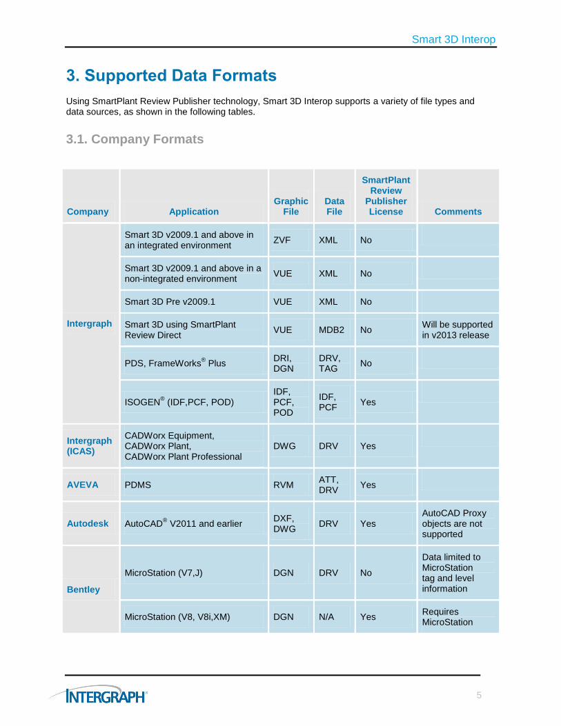
3. Supported Data Formats
Using SmartPlant Review Publisher technology, Smart 3D Interop supports a variety of file types and data sources, as shown in the following tables.
3.1. Company Formats
Company Application Graphic
File Data File
SmartPlant Review
Publisher License Comments
Intergraph
Smart 3D v2009.1 and above in an integrated environment
ZVF XML No
Smart 3D v2009.1 and above in a non-integrated environment
VUE XML No
Smart 3D Pre v2009.1 VUE XML No
Smart 3D using SmartPlant Review Direct
VUE MDB2 No Will be supported in v2013 release
PDS, FrameWorks® Plus
DRI, DGN
DRV, TAG
No
ISOGEN® (IDF,PCF, POD)
IDF, PCF, POD
IDF, PCF
Yes
Intergraph (ICAS)
CADWorx Equipment, CADWorx Plant, CADWorx Plant Professional
DWG DRV Yes
AVEVA PDMS RVM ATT, DRV
Yes
Autodesk AutoCAD® V2011 and earlier
DXF, DWG
DRV Yes AutoCAD Proxy objects are not supported
Bentley
MicroStation (V7,J) DGN DRV No
Data limited to MicroStation tag and level information
MicroStation (V8, V8i,XM) DGN N/A Yes Requires MicroStation

Smart 3D Interop
6
3.2. Industry-standard Formats
Industry Application Graphic
File Data File
SmartPlant Review
Publisher License Comments
Open Standards
CIS/2 STP DRV Yes
XMpLant XML DRV Yes
Mechanical Applications
ACIS (Solid Format) SAT N/A Yes Graphics only
Smart 3D using SmartPlant Review Direct
IGES, IGS
N/A Yes Graphics only

Smart 3D Interop
7
3.3. Generic Formats
The previous lists are not exhaustive because some of the formats are generic, in which case, any system supporting these formats will, by inference, be supported. These include:
System Format Comments
Tekla , StruCAD, Xsteel, FrameWorks Plus, SDS/2, Autodesk Revit, RAM Steel, ETABS, SAP2000, RISA-3D, Advance Steel, GT STRUDL, STAAD.Pro, ProSteel
CIS/2 For graphic data only, or data not supported in CIS/2, MicroStation or AutoCAD could be used for most of these systems
BOCAD CIS/2 SDNF to CIS/2 Conversion via FrameWorks Plus
SACS CIS/2 or ACIS (SAT)
SDNF to CIS/2 Conversion via FrameWorks Plus
Export SAT directly from SACS
AutoPLANT, PlantSpace AutoCAD, ISOGEN
ANSYS Workbench ACIS (SAT)
SolidEdge, SolidWorks, AutoCAD Inventor, CREO Parametric (formerly Pro/Engineer), Siemens, Catia
ACIS (SAT)
SmartPlant Spoolgen®,
SmartPlant Isometrics ISOGEN
CAESAR II® ISOGEN
JT Open SAT JT Open to SAT conversion by Theorem
Speedikon, Tribon M2 / M3 MicroStation
ShipConstructor AutoCAD Graphics Only

Smart 3D Interop
8
4. Step by Step
When registered in an integrated environment, Smart 3D from v2009.1 and above will create .zvf and .xml files which can be used directly with Smart 3D Interop. Non-integrated plants and older Smart 3D versions or third party systems will create files in the formats listed in section 3.
These files are then converted for use with Smart 3D Interop. The resulting converted files are then referenced, mapped, rotated, positioned, and scaled in the Smart 3D Project Management application. Once referenced; the Smart 3D Interop model data is available for use in the 3D model for interactive design, including connectivity, clash checking, drawings, and more.
This section explains, in a step by step manner, the processes involved and the capabilities of the software in the use of this referenced data. Please note this is not intended as a user guide.
4.1. Graphic and Data File Generation
Typically the files will be in pairs (graphics and data) as listed in section 3. Detailed instructions for the creation of the required files in Smart 3D, PDS, and PDMS are available.
4.2. Graphic and Data File Conversion for Use in Smart 3D
With the exception of .zvf and .xml files generated by Smart 3D v2009.1 and above in an integrated environment which can be used directly, graphics and optional data files as listed in section 3 will need to be converted to the streamed version supported by Smart 3D. The “ConvertToZVF” utility is installed with Smart 3D and can be found in the product folder.
This utility will automatically detect the source file type. Depending on the source of the files being converted, a SmartPlant Review Publisher license may be required. An error message will launch if this license is not available when needed.
After conversion, sets of .zvf and .xml or .drv files will be generated in the output folder.

Smart 3D Interop
9
4.3. Objects and Properties Mapping
The Smart 3D Interop schema is a lightweight schema that includes the basic classes and their properties. The 3D Interop schema is based on the P3D schema, which is the schema used to publish Smart 3D data to SmartPlant Foundation. Because of this, the 3D Interop schema is a subset of the P3D schema. Discipline-specific 3D Interop objects, as well as their hierarchy and basic properties, are defined in the delivered 3D Interop schema as shown.
The properties of the 3D Interop schema classes are grouped into interfaces for logical access. In addition to specifying classes and their properties, the 3D Interop schema enables you to meld these new classes into the Smart 3D Business Object Classification hierarchy so that all these classes may be presented in an organized fashion for filtering.

Smart 3D Interop
10
Classes and properties from other tools may be mapped to the classes and properties in the R3D schema by specifying such mapping in a simple Excel
® spreadsheet.
Upon loading the Smart 3D Interop data, properties will then be listed in the property dialog and can be used for labels in tooltips, drawings and reports.
You may customize the delivered mapping file to modify or add mapping to additional classes or properties. In addition to the standard schema delivered, Smart 3D also allows you to extend the schema through customization.
See the Project Management User’s Guide for full instructions on modifying the Smart 3D schema and mapping files.
Smart 3D Interop
11
4.4. Smart 3D Interop Tools
To aid in the administration of reference models and the management of data from other sources, in addition to the ConvertToZVF tool as described in section 4.2, Smart 3D Interop provides a number of other tools. See the Project Management User’s Guide for full instructions on using these tools.
4.4.1. Schema Generator Tool
The Schema Generator tool reads .drv files and extracts information about the schema of the tool that generated the data. Data from sources other than Smart 3D is processed by the ConvertToZVF tool and made available for referencing by Smart 3D in the form of .drv files.
4.4.2. Generate Mapping Tool
The Generate Mapping tool is used to create the schema and mapping files which are used for property mapping when attaching a reference model in Project Management.
The generated files will list source classes and their properties. By specifying additional information for mapping, such as target class and interfaces, the property data will be displayed against the objects in Smart 3D.

Smart 3D Interop
12
4.5. Reference Model Attachment in Project Management
Attaching reference models in Smart 3D is performed in the Project Management environment. Any number of supported format models can be independently attached, rotated, positioned, and scaled using the “New Reference 3D model” function.
The following model types are supported:
Smart 3D
PDMS
PDS
Generic Use this option for all reference 3D models whose data files are in the standard .drv format.
Graphic_Only Use this option for all reference 3D models that do not have data files.
Note that default mapping files are supplied for PDS and PDMS data.
Following attachment, the referenced model can be updated for both model changes and mapping changes. It can also be rotated, positioned, and scaled from the properties dialog.
Updating the Reference 3D or the CustomReference3D schema packages causes other Smart 3D Interop models that are attached to any Smart 3D models that use the same catalog database to be displayed as out-of-date. A Smart 3D Interop model can also become out-of-date if any of the input files in the referenced model folder are updated. The icon displayed in the Project Management tree view for an out-of-date 3D Interop model indicates its out-of-date status, as shown below:

Smart 3D Interop
13
4.6. Smart 3D Workspace Definition
Following the attachment of a reference model, it is first necessary to create a new Smart 3D session file. Referenced models are displayed on the Reference 3D tab in the filter properties dialog.
In addition, filters as described in section 4.7 can also be used to bring objects into the workspace.
Smart 3D Interop
14
4.7. Filters
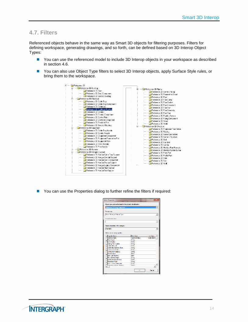
Referenced objects behave in the same way as Smart 3D objects for filtering purposes. Filters for defining workspace, generating drawings, and so forth, can be defined based on 3D Interop Object Types:
You can use the referenced model to include 3D Interop objects in your workspace as described in section 4.6.
You can also use Object Type filters to select 3D Interop objects, apply Surface Style rules, or bring them to the workspace.
You can use the Properties dialog to further refine the filters if required:
Smart 3D Interop
15
4.8. View Style Definition
Surface style rules are based on filters. When you create or modify rules, you specify a filter on which to base the rule.
If you want objects to appear consistently in certain colors, textures, and other formats in your workspace, you can define their appearance by applying surface style rules. These rules apply to all existing objects in your workspace that meet the rule filter. The rules also apply to any new objects you place in the workspace that meet the filter.
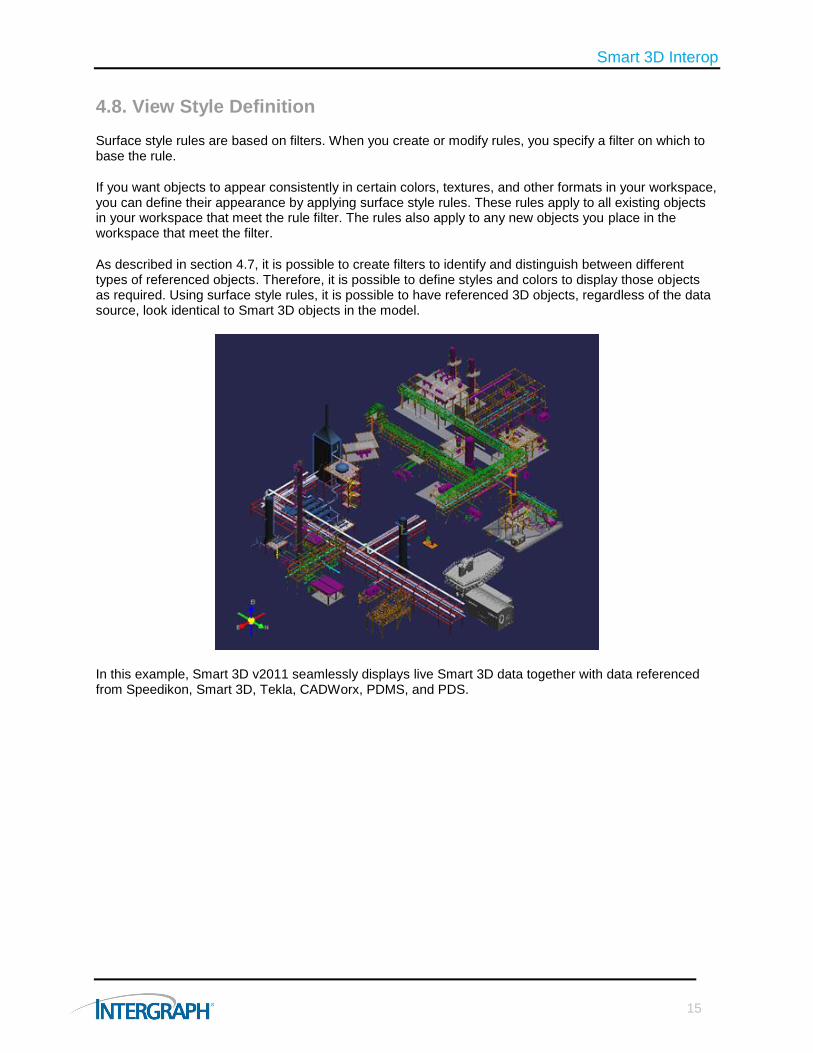
As described in section 4.7, it is possible to create filters to identify and distinguish between different types of referenced objects. Therefore, it is possible to define styles and colors to display those objects as required. Using surface style rules, it is possible to have referenced 3D objects, regardless of the data source, look identical to Smart 3D objects in the model.
In this example, Smart 3D v2011 seamlessly displays live Smart 3D data together with data referenced from Speedikon, Smart 3D, Tekla, CADWorx, PDMS, and PDS.

Smart 3D Interop
16
4.9. Clash Checking
Interference checking (IFC) ensures that parts do not occupy the same volumetric space and that each part meets the design criteria for clearance. A successful interference check ensures that there is sufficient space around the parts so that they can operate properly, be serviced properly, and be easily installed or removed when necessary. The IFC process can look at all model data, including data from a 3D Interop model.
Interference checking 3D Interop data consists of rules that control the interference checking process. The rules include pre- and post-processor rules, as well as a clearance rule. The rules used for 3D Interop objects are Foreign Object Rules.
You can stop any reference model from participating in the interference checking processes if required. However, if selected when attaching a reference model, 3D Interop objects will participate in the clash check and are checked against Smart 3D objects and other 3D Interop objects in different data sets. They are not checked against 3D Interop objects in the same data set.
4.10. Connections to Referenced Objects
Before Smart 3D version 2011, non-graphical nozzles were required to be placed at the point of each connection between referenced objects and Smart 3D objects prior to connection. The connection information would then be used to place, using rules within the piping specification, the correct connection. With Smart 3D version 2011, when the reference object is selected, an “on-the-fly” connection is created and the user is presented with the connection information dialog where the intelligent nozzle or connection information can be inputted:

Smart 3D Interop
17
4.11. Label Creation
Within Smart 3D, labels are used as a method for returning object information. Labels on referenced objects work in the same way as labels on regular Smart 3D objects. Using the 3D Interop Schema, labels can be created to return properties of 3D Interop objects and can be used as tool tips and in drawings and reports. This means that in the same way as for creating filters as described in section 4.7, numerous reports and orthographic drawing types can be generated from referenced data by using labels.
It should be noted that properties returned from reference objects are always in the string format.
Label templates using the 3D Interop schema are created in the catalog task. This image shows how a user returns the name (tag) of a referenced instrument. Many properties are available and dependent on the mapping. As described in section 4.3, the values will be returned by the label.
Here the label is used as a tool tip.

Smart 3D Interop
18
4.12. Drawings and Reports
The Drawings and Reports task creates isometric drawings, orthographic drawings, and reports from the model.
4.12.1. Piping Isometric Drawings
It is not possible to generate piping isometrics through ISOGEN from Smart 3D Interop objects.
However, isometrics of Smart 3D piping, connected to Smart 3D Interop objects, are fully supported as shown here.
Piping isometric drawing showing continuation label to 3D Interop nozzle and detailed MTO for connection
4.12.2. Orthographic Drawings
Orthographic drawings are created using rules contained in a view style. The view style consists of a number of filters to distinguish between object types, together with rules for graphic display, labeling, and dimensioning.
As detailed in section 4.7, filters are supported on referenced objects. Because graphic rules are filter-based, these are inherently supported. As described in section 4.11, labels are supported on referenced objects. Label positioning and dimension rules rely on various points being automatically generated from the 3D objects. Unfortunately, the points currently generated from referenced objects mean that only some basic label positioning and dimensioning can be created automatically. Manual labeling and dimensioning of referenced objects is supported in the 2D drawing environment, SmartSketch
®.

Smart 3D Interop
19
In summary, dependent on the mapping of the referenced data to the correct 3D Interop object types, orthographic drawings with labels and limited automatic dimensioning are supported. Manual dimensions can be added if required. It is also supported to have a mix of 3D Interop objects and Smart 3D objects on the same drawing as shown in these examples.
Orthographic drawing showing 3D Interop equipment and nozzles, 3D Interop piping, Smart 3D piping, and 3D Interop steel with automatic labels
Typical orthographic equipment plan drawing showing 3D Interop equipment and nozzles, 3D Interop steel, including automatic labels and dimensions

Smart 3D Interop
20
4.12.3. Reports
Reports are created from templates using filters to distinguish between object types and labels for returning the property values to be displayed. Microsoft Excel is then used to perform sums, totals, and more.
As detailed in section 4.7, filters are supported on referenced objects. Section 4.11 described labels in string format are supported on referenced objects. Therefore, generating reports on referenced data is supported as shown here.
3D Interop equipment list report (across all 3D Interop models)

Smart 3D Interop
21
4.13. Global Workshare
Smart 3D offers built-in capabilities to enable multiple users to work on a single project, dispersed across numerous locations and networks. The two main technologies used to achieve this with Smart 3D are Citrix XenApp and Global Workshare.
Using these technologies, all users have access to the full model. This capability may not always be desirable. Therefore, a 3D disconnected workshare can be used to allow only a portion of the model to be made available to a particular workshare participant. This would be supported by the use of Smart 3D Interop together with Global Workshare.
The Smart 3D Interop functionality was designed and developed with the intent of ensuring intellectual property protection. Smart 3D Interop offers control over confidential data and provides a mechanism to share non-confidential data with offshore design centers as well as joint venture partners. Intergraph recommends adopting Smart 3D Interop for securing confidential data in a workshare environment as shown in this diagram.
For the effective management of interfaces, a buffer zone should be established. Using Smart 3D Interop, this can safely be distributed to all workshare participants.

Smart 3D Interop
22
5. Limitations
Smart 3D Interop data is treated intelligently and can be used with many of the Smart 3D concepts and rules. However, because this is not “real Smart 3D data,” a number of limitations exist, including:
3D Interop objects cannot be modified in Smart 3D. Any modification should be performed in the source system. The graphic and data files should be re-extracted and converted. The model can then be refreshed in the Project Management environment.
It is not currently possible to create ISOGEN piping isometrics from Smart 3D Interop objects.
Label positioning is limited to “Clear Space,” “Margin,” etc. Object positioning, such as “Longest Length” in orthographic drawings, is not supported.
Only basic automatic dimensioning of Smart 3D Interop objects is possible in orthographic drawings.
Smart 3D Interop objects are not published to SmartPlant Foundation.
AutoCAD proxy objects are not supported.

Smart 3D Interop
23

For more information about Intergraph, visit our website at www.intergraph.com.
Intergraph, the Intergraph logo, SmartPlant, SmartMarine, PDS, FrameWorks, ISOGEN, Spoolgen, CADWorx, and SmartSketch are registered trademarks of Intergraph Corporation or its subsidiaries in the United States and in other countries . Microsoft and Excel are registered trademarks of Microsoft Corporation. AutoCAD is a registered trademark of Autodesk Inc. Other brands and product names are trademarks of their respective owners. Intergraph believes that the information in this publication is accurate as of its publication date. Such information is subject to change without notice. Intergraph is not responsible for inadvertent errors. ©2012 Intergraph Corporation. All Rights Reserved. 05/12 PPM-US-0165A-ENG