Embed Size (px)
Citation preview

www.ijecs.in International Journal Of Engineering And Computer Science ISSN:2319-7242 Volume 2 Issue 6 June, 2013 Page No. 1704-1726
V.C. Ossai, IJECS Volume 2 Issue 5 May, 2013 Page No. 1704-1726 Page 1704
SMARESiM: AN IMPROVED MODEL OF E-VOTING SYSTEM BASED
ON BIOMETRIC KEY BINDING V.C. Ossai *, K.C. Okafor, H.C. Inyama , A.O. Agbonghae.
Electronics Development Institute, Awka.
ABSTRACT
E-VOTING is a term used to encompass the various techniques applied, through which the electorate or voters
can express their intentions electronically. It entails the use of electronic voting equipment, phones, Personal
Data Assistants (PDA), online voting etc. The adoption of e-governance strategy in electioneering processes
(using Nigeria context- 36 states) will effectively reduce cost as well as enhancing election activities. What makes
an e-voting model acceptable is its ability to properly authenticate voters and provide a secure means through
which a voter can express his/her franchise. Adopting biometrics authentication is regarded as an effective
method for automatically recognizing, with a high confidence, a person’s identity. This paper therefore, proposes
Self-Monitoring Analysis and Reporting E-Voting Simulation Model (SMARESiM), a design model of an e-
voting system leveraging on Biometric Encryption (BE) viz Biometric key Binding (BKB) which is a secured
strategy that entails fusing of biometrics with cryptographic schemes. The main objective of this research is to
improve on the already existing E-voting models by fusing and adopting biometric and cryptographic techniques
as well as using a secure transmission channel for confidential datasets of a voting process. This work develops a
simulation model of an E-voting system which adopts relevant algorithms and mathematical equations with
emphasis on biometric security schemes. The simulation of a prototype model of the electronic voting system
would be developed using Proteus 7.6 application software (a simulation model). Relevant algorithms and flow
models are presented while developing the SMARESiM with PROTEUS ISIS coded in Assembly Language. The
prototype model would consist of electronic kiosk polling booths (two e-booths) that are all networked to the state
electoral collection center and two state collection centers (in this model) are networked to the national electoral
collection center via a VPN backbone. The proposed SMARESiM uses a Virtual Private Network (VPN) as the
means of communication between the various polling booths and collection points. The VPN platform provides a
fast, safe and reliable means of transmitting data over the internet. The results of validation show that the
proposed model facilitates the adoption of E-governance in the developing countries.
KEYWORDS: E-voting Booths, Biometrics, Cryptology, Security, Privacy, BE, VPN.
1. INTRODUCTION
Election is a process by which members of an organization or a society select people to hold offices of authorities. It
may be conducted by ballots, rising of hands, oral voting and now the use of electronic voting system. Voting could
also be used award prizes, to select between different plans of actions etcetera [1].
The term ―e-voting‖ is used, in variety of different ways mainly and it encompasses all voting techniques involving
electronic voting equipment, including voting over the internet, using booths in polling stations (e-booths) and
sometimes even from remote sites (e.g. via SMS). Electronic voting encompasses several different types of voting
embracing both electronic means of casting votes and electronic means of counting votes. According to [2] e-voting
is any voting method where the voter‘s intention is expressed or collected by electronic means. The following e-
voting approaches have being identified in the literature, viz;
- Kiosk voting (e-booths) means the use of dedicated voting machines in polling stations or other controlled
locations. In this scheme, voters mark their choice electronically (on the electronic voting machine) rather
than on paper ballot. The votes are counted on individual machines, known as Direct Recording Electronic
(DRE) machines, and the votes cast are transferred to the central tallying point by unspecified means.

V.C. Ossai, IJECS Volume 2 Issue 5 May, 2013 Page No. 1704-1726 Page 1705
- Remote electronic voting is the preferred term for voting that takes place by electronic means from any
location. This could include the use of text message, multimedia message, interactive digital TV or touch
tone telephone.
- Internet voting (I-voting) is a specific case of remote electronic voting, whereby the vote takes place over
the Internet such as via a web site or voting applet. Sometimes also used synonymously with Remote
Electronic Voting.
Basically, this work uses the term e-voting with the specific reference to kiosk voting (e-booth) over the internet
(through a secure public infrastructure). This is discussed in the SMARESiM design model developed in this work.
In an Electronic Voting System the main components of the process include [2]:
i. The Electronic Voters Register- which is a comprehensive database of eligible voters.
ii. Authentication- which is done prior to balloting. This is based on the use of a secure biometric
identification algorithms and schemes.
iii. Voting, Collation and Transmission- the election results directly from each of the polling
stations are sent to designated collation centers in real time.
In this case, it would involve the use of some of Direct Recording Balloting Machines (Electronic Voting Machines)
connected over a VPN (secure internet facility), this will completely eliminate the cost associated with the printing
of several million ballot papers.
The use of biometric encryption techniques and secured communication channels to transmit voting results which is
being adopted in this simulation model would reduce to the barest minimum the fraud and irregularities associated
with elections. As such, by adopting the fingerprint Biometric Encryption (BE) technique viz Biometric Key
Binding (BKB), the proposed model takes care of the security and privacy concerns of the electorate. Worthy of
note is that BKB has not yet been adopted in E-voting systems.
2. LITERATURE REVIEW
2.1 Related Works
The work in [3] presented e-voting Schemes and explained that e-voting is a promising application of cryptography,
which can have positive impact on democratic process. The work discussed cryptographic aspects of constructing e-
voting schemes and approached the scheme from three perspectives viz: scientific, technical, and politico-
sociological and tried to generate a preliminary framework on the notion of choice. The author added that on the
internet, implementing cryptographic protocols like digital encryption and signature has been widely accepted.
The authors in [4] described the theory behind a practical voting scheme based on homomorphic encryption and
gave an example of an ElGamal-style encryption scheme, which can be used as the underlying cryptosystem. The
work presented the most important goals for electronic voting schemes viz: Privacy, Robustness, Universal
verifiability and freeness.
Fundamentally, different approaches to electronic voting are known in the literature such as the use of blind
signatures and anonymous channels [5], where the channels can be implemented using MIX nets [6],[7] for instance
or be based on some physical assumption [4]. The idea in such a scheme is that a voter prepares a ballot in clear text,
i.e., a message stating for whom he votes [4]. He then interacts with an authority that can verify that he is eligible to
vote and has not already voted. If this is the case, the authority issues a blind signature on the ballot. Informally, this
means that the voter obtains the authority's digital signature on the ballot, without the authority learning any
information about the contents of the ballot. On the other hand, a voter cannot obtain such a signature without
interacting with the authority, and is therefore prevented from voting several times [4].
The work in [8] presents an evaluation of e-Voting systems equipped with voter-Verified Paper Records.
The work stated that owing to the need to increase public confidence, various states are increasingly considering
electronic voting systems that provide voter verified paper records. In the work, an analysis and evaluation of New
Jersey‘s criteria against several different e-voting machine types revealed potential threats and possible solutions on
privacy, security, and performance issues. The authors in [9] propose a secure electronic voting protocol that is
suitable for large scale voting over the Internet. In their work, the protocol allows a voter to cast his or her ballot
anonymously, by exchanging untraceable yet authentic messages. The protocol ensures that (i) only eligible voters
are able to cast votes, (ii) a voter is able to cast only one vote, (iii) a voter is able to verify that his or her vote is
counted in the final tally, (iv) nobody, other than the voter, is able to link a cast vote with a voter, and (v) if a voter
decides not to cast a vote, nobody is able to cast a fraudulent vote in place of the voter [9]. The following
assumptions were made in the context of this protocol viz [9]:
i. Hard-to-invert permutations: A permutation of a finite set of numbers whose inverse is hard to compute.

V.C. Ossai, IJECS Volume 2 Issue 5 May, 2013 Page No. 1704-1726 Page 1706
ii. Blind Signature on messages: A verifiable transformation of a message which can only be generated by the
signing entity. Using publicly available information, anyone can verify the signature. In a blind signature, the
signing entity signs a message without knowing its contents [3], [4]. The message that is submitted for blind
signature can be freely published without revealing the actual message.
iii. Secure Transit: An encryption scheme that ensures privacy and integrity of messages in transit.
Consequently, the voting protocol employs three, agents for successful operation viz:
i. BD: A ballot distributor who prepares blank ballots and distributes one to each voter.
ii.CA: a certifying authority, who verifies eligibility, certifies ballots and ensures that a voter gets only one certified
ballot.
iii.VC: A vote compiler who tallies the votes and announces the results.
In their final analysis, the work concludes that the protocol is suitable for large scale voting over the Internet and
that satisfies the core properties of secure voting systems – namely accuracy, democracy, privacy and verifiability.
The authors in [10], observed that the traditional methods of electioneering is characterized by long period
of preparation, fake voting, faulty voting, mistakes made in counting the votes, long period of counting and high
cost of voting process. In order to avoid these limitations, (which directly affects the economy and policy of the
countries involved), the work proposed an e-voting system for general elections. The system applied biometric
fingerprint authentication. In the work, a biometric based e-voting system is designed for providing a secure election
on electronic environment for the electors. Technologies such as XSL language which is compatible with Asp.Net,
Framework 2.0, Java Script, Xml is used but can be deployed in Microsoft Windows operating system [10]. Again,
the, biometric based software libraries are also used for integrating the fingerprint control to the system. In this
regard, the elector identification system is programmed with C# language and equipped with an optical fingerprint
scanner SDK (Suprema Inc®) to accept a scan, recognize the elector, and open the correct elector record in the
database and verify system (Suprema, 2010). This module uses a dynamic link library (DLL) that can be displayed
in a web application as shown in Figure 1.
Figure1 General structure of a fingerprint device program.
As shown in figure 2a, figure 2b, figure 2c, all of the biometric logon modules have two parts: A web application,
which is a webpage with program logic running behind it, for data collection and a web service for verification. The
e-voting web application is allowed to interface with the physical biometric device but not the database containing
the enrolled user data, while the web service can do the exact opposite [10].

V.C. Ossai, IJECS Volume 2 Issue 5 May, 2013 Page No. 1704-1726 Page 1707
Figure 2a User interface for system login Figure 2b. Election defining screen [10]
Figure 2c Fingerprint information is scanned and stored in the database [10].
Attacks are indispensible in biometric based systems, hence besides privacy issues, the major identified limitations
of the works discussed above is presented. Applying texture-based feature extraction techniques to fingerprint
authentication is very vulnerable. In this case, its security properties considering biometric integration is very
vulnerable as attackers, Trojan horses, etc. Biometric technologies may add a new level of authentication and
identification to applications, but are not, however, without their risks and challenges. There are important
technological challenges such as accuracy, reliability, data security, user acceptance, cost, and interoperability, as
well as challenges associated with ensuring effective privacy protections. Some common security vulnerabilities of
biometric systems include: spoofing; replay attacks; substitution attacks; tampering; masquerade attacks (creating a
digital ‗‗artifact‘‘ image from a fingerprint template so that this artifact, if submitted to the system, will produce a
match); Trojan horse attacks; and overriding Yes/No response (which is an inherent flaw of existing biometric
systems [11].
All feature extraction e-voting models are weak. A traditional biometric system will store the original templates in a
database, for use in authentication/identification comparisons. If an attacker can gain access to the database (despite
its security measures) then all template data (X) can be compromised [11].

V.C. Ossai, IJECS Volume 2 Issue 5 May, 2013 Page No. 1704-1726 Page 1708
Figure3 An attacker compromises the database, and retrieves the template X [11]
2.2. Biometric Encryption (BE) Proposal Adopted in SMARESiM
The concept of Biometric Encryption (BE) was first introduced in the mid-‗90s by Tomko et al. [12] and is adopted
in SMARESiM proposed model. BE is a process that securely binds a key to, or extracts a key from, a biometric,
such that neither the key nor the biometric can be retrieved from the ―helper data‖ (also called a ―private template‖)
created by this process and stored by the application, except upon presentation of the correct live biometric sample
for verification. In essence, the key is ―encrypted‖ with the biometric — a ‗fuzzy‘ process due to the natural
variability of biometric samples. It is a group of emerging technologies that securely bind a digital key to a
biometric or generate a digital key from the biometric, so that no biometric image or template is stored. What is
stored is the BE template otherwise known as a ‗‗bio-metrically encrypted key‘‘ or ‗‗helper data‘‘. As a result,
neither the digital key nor the biometric can be retrieved from the stored BE template which stored. And to retrieve
the original image from the encrypted template is impossible.
Helper data are obtained by binding a chosen key to a biometric template. As a result of the binding process, a
fusion of the secret key and the biometric template is stored as helper data. Applying an appropriate key retrieval
algorithm, keys are obtained from the helper data at authentication [13]. Since cryptographic keys are independent
of biometric features, these are revocable while an update of the key usually requires reenrollment in order to
generate new helper data. They extract an array of phase values from the fingerprint image using a Fourier transform
and apply majority coding to reduce the feature variation. Instead of generating a key directly from biometrics, they
introduce a method of biometric locking: a pre-defined random key is ―locked‖ with a biometric sample by forming
a phase-phase product (i.e., the dot product of the extracted phrase array and a random-value array). This product
can be unlocked by another genuine biometric sample. A sophisticated approach to biometric key-binding based on
fingerprints was proposed by Soutar et al. [14], [15]. With BE, the digital key is recreated only if the correct
biometric sample is presented on verification.
The output of BE verification is either a digital key or a failure message. This ‗‗encryption/decryption‘‘ process is
fuzzy because of the natural variability of biometric samples.
2.2.1 Adopted BEOperational Models
The Operational mode is depicted in figure 5, figure 6, and figure 7 below. At enrollment a filter function, H(u), is
derived from f0(x), which is a two dimensional image array (0 indicates the first measurement). Subsequently, a
correlation function c(x) between f0(x) and any other biometric input f1(x) obtained during verification is defined by
c(x) = FT−1{F1(u)F∗0(u)} ……………………………….(1)

V.C. Ossai, IJECS Volume 2 Issue 5 May, 2013 Page No. 1704-1726 Page 1709
which is the inverse Fourier transform of the product of the Fourier transform of a biometric input, denoted by F1(u),
and F∗0(u), where F∗0(u) is represented by H(u). The output c(x) is an array of scalar values describing the degree
of similarity [14].
To provide distortion tolerance, the filter function is calculated using a set of T training images {f01 (x), f0
2 (x) . . . ,
f0T (x)}.
The output pattern of f0T (x) is denoted by c0
T (x) with its Fourier transform F0T (u)H(u) . The complex conjugate of
the phase component of H(u), eiɸ(H(u), is multiplied with a random phase-only array of the same size to create a
secure filter, Hstored(u), which is stored as part of the template while the magnitude of H(u) is discarded. The output
pattern c0(x) is then linked with an N-bit cryptographic key k0 using a linking Algorithm I.
Algorithm I: Linking k0 with c0(x)
Begin ()
If (the n-th bit of k0 = 0) then L locations of the selected part of c0(x) which are 0 are chosen and the indices of the
locations are written into the n-th column of a look-up table which is stored as part of the template, termed
Bioscrypt.
During linking, redundancy is added by applying a repetitive code. Standard hashing algorithms is used to
compute a hash of k0, termed id0 which is stored as part of the template, too.
During authentication, a set of biometric images is combined with Hstored(u) to produce an output pattern
c1(x). With the use of the look-up table, an appropriate retrieval algorithm calculates an N-bit key k1 extracting the
constituent bits of the binarized output pattern.
Finally, a hash id1 is calculated and tested against id0 to check the validity of k1. The algorithm was summarized in
[14].
Figure 5 below summarizes the working mechanism for enrollment process the Biometric Key Binding
technique; fig 6 summarizes the verification process while fig 7 is a summary of the enrollment and verification [15]
which is adopted in this work for the SMARESIM.
Random
Array
STAGE En-2
Link k0 (N-bit key) Algorithm
… Co(x)
… S bits
of
Hstored
Hstored(u) (u)
STAGE En-1 ido STAGE
En-3
Figure 5: Enrollment Process Model for BE [14]
Image
Processing
Look up table
Encrypt
Hash
Bioscrypt

V.C. Ossai, IJECS Volume 2 Issue 5 May, 2013 Page No. 1704-1726 Page 1710
Figure 7: Composite Process Model for Enrollment and Verification in BE System [15].
ENROLLMENT AUTHENTICATION
BIOSCRYPT
Retrieval
Algorithm
Output
Pattern
C0(x)
Image
Processing
Linking
Algorithm
Key k0
Random
Array
Identification
code
Look up
Table
Hstored(u)
Key k1
Output
Pattern
C1(x)
Image
Processing
Biometric Inputs
Biometric Inputs
C1(x)
Hstored(u)
Look up table Image
Processing Encrypt
Hash Bioscrypt
S bits of Hstored(u)
Compare
STAGE ve-2
Retrieval
Algorithm K1 (N-bit Key)
STAGE Ve-1 id0
id1 STAGE Ve-3
Figure 6: Verification Process Model for BE [14]

V.C. Ossai, IJECS Volume 2 Issue 5 May, 2013 Page No. 1704-1726 Page 1711
3. COMMUNICATION NETWORK PLATFORM
3.1. Multi-Protocol Label Switch -Open Virtual Private Network (MPLS-OVPN)
This work identified MPLS-VPN as an important solution to security threats surrounding the use of public
networks .It offers a secure network connection between a sender and a receiver over a public non- secure network.
A VPN transforms the characteristics of a public network into those of a private secure network and provides the
means to securely transmit data between two networked devices over an insecure transport medium [16]. A VPN
works by creating a tunnel, on top of a protocol such as IP. It enables cooperate entities to use the internet as a
virtual backbone (for the co-operate networks) by allowing them to create secure virtual links between their co-
operate headquarters and remote sites via the internet.
In the characterization of the proposed SMARESiM, the polling booths at the various wards would be
characterized as the remote INEC offices, the state INEC collection centers would be characterized as the branch
offices while the INEC headquarters in Abuja is characterized as the co-operate office. But when compared to other
solutions e.g. leased lines, VPNs are relatively inexpensive.
VPN makes use of many security mechanisms e.g. encryption, the use of digital signature to ensure that data cannot
be modified without detection [16]. It uses tunneling process to transport the encrypted data over the internet.
Tunneling is mechanism for encapsulating one protocol in another protocol [16]. In the context of internet, tunneling
allows protocol such e.g. AppleTalk, IP to be encrypted and encapsulated in IP envelop which is then transmitted
safely over the internet. At the receiving side, the IP envelop is removed, the data is decrypted and delivered to the
appropriate device. The VPN architecture consists of the VPN client, Network Access Server (NAS), A Tunnel
terminating device (VPN sever), and a VPN protocol.
3.1.1. Open VPN Solution
OpenVPN is a VPN solution adopted in proposed SMARESiM model. This work characterizes tunneling of traffic
through transport layer using TCP (Transmission Control Protocol) for encapsulation and transfer of data. It uses
VNI (Virtual Network Interface) for capturing in coming traffic before encryption and sending outgoing traffic after
decryption. Security is using standard encryption algorithms such as the AES 128 (Advanced Encryption Standard).
The VNI appears as the actual network interface to all applications and users. Packets of data sent via the VNI are
delivered to programs attached to the VNI.
Essentially, an OpenVPN performs the following viz:
1) Receives packets of data (votes) from the polling booths using VNI (Virtual Network Interface).
2) After receiving the packets, it compresses the packets.
3) After compression, it encrypts the packets making use of the AES-128.
4) It tunnels the packet using the TCP (Transmission Control Protocol) to the other end.
5) On receiving the encrypted traffic, the OpenVPN performs the reverse of cryptographic operations to verify
integrity and authenticity.
6) After completing the reverse cryptographic operations, it decompresses the packets.
7) The decompressed data (recovered votes) is passed by the VNI to the user interface. Figure 8 depicts the
model of an OpenVPN Tunnel for two remote sites.

V.C. Ossai, IJECS Volume 2 Issue 5 May, 2013 Page No. 1704-1726 Page 1712
Figure 8: A Model of OpenVPN Tunnel between two end points A and B [16]
Figure 9: The Flow diagram of MPLS -VPN backbone for the proposed SMARESIM
Fig 8 above shows an operational model of an OpenVPN tunnel between points A and B. Fig 9 shows the flow
diagram of information between the various polling booths in different wards, the state and national collection
centers as characterized by the SMARESiM over a secured network facility.
An innovative technique for securing a key using a biometrics i.e. biometric key binding as characterized in fig 10
below is adopted in this work SMARESIM (Self-Monitoring and Reporting Electronic Voting Simulation
Model). The digital key is linked with a biometric trait at a more fundamental level during enrollment, and is later
retrieved using the same biometric trait during verification.
Furthermore, the key is completely independent of the biometric data, which means that, firstly, the use of the
biometric is not forfeited if the key is ever compromised, and secondly, the key can be easily modified or updated at
a later date. We can refer to the biometrically encrypted template as a cancelable fingerprint. During enrollment, the
Biometric Encryption process combines the biometric image with a digital key (which is randomly generated and
not known even to the user) to create a secure block of data, known as a Bioscrypt. The digital key can be used as a
cryptographic key.The Bioscrypt is secure in that neither the fingerprint nor the key can be independently obtained
from it.During the voter verification, the Biometric Encryption algorithm retrieves the cryptographic key by
combining the biometric image with the Bioscrypt. Thus, Biometric Encryption does not simply provide a yes/no
response in user authentication to facilitate release of a key, but instead retrieves a key that can only be recreated by
combining the biometric image with the Bioscrypt. It is this cryptographic key obtained that now allows the verified
voter, access to the e-voting system.
After the voter cast his vote for the party of his choice, the votes is split into packets of data, which is
encapsulated another packet with headers and then tunneled over a secured network facility (a VPN for this model).
Open VPN Process
WARD 2
State collection
center in Abia
State collection
center in Anambra
VPN MPLS
INTERNET
INEC
HQS
WARD 1
Host B Host A
Tunnel
Open VPN Process Open VPN Process
VPN

V.C. Ossai, IJECS Volume 2 Issue 5 May, 2013 Page No. 1704-1726 Page 1713
At the receiving end (collection centers), the encapsulated packets is de- encapsulated (the encapsulation and de-
encapsulation is done via AES 128 encryption standards). The votes are now tallied at the respective collection
centers and the final tally is done at the INEC national headquarters in Abuja.
This operation is summarized in fig 10 below which shows an analytical representation of the enrollment
and authentication in the Biometric Key Binding (BKB) technique as adopted and characterized in the proposed
SMARESi
Figure 10 an analytical model for enrollment and verification
F
P
R
I
N
F
P
R
I
N
LINKING
ALGORITHM
IDENTIFICATION
CODE
LOOK UP
TABLE
HSTORED(U)
KEY k0
OUTPUT
PATTERN
C0(x)
RETRIEVAL
ALGORITHM
KEY k1
OUTPUT
PATTERN
C1(x)
IMAGE
PROCESSIN
G
RANDOM
ARRAY
IMAGE
PROCESSIN
G
F
P
R
I
N
F
P
R
I
N
Biometric Inputs
Biometric Inputs
AUTHETICATION ENROLLMENT
IF
ID1=ID0
RELEASE
K1
CAST A
VOTE
SPLIT,
ENCRYPT &
TUNNEL VOTE
DECRYPT
VOTE &
COMPILE
RESULTS
Bioscript

V.C. Ossai, IJECS Volume 2 Issue 5 May, 2013 Page No. 1704-1726 Page 1714
in a biometrically encrypted E-voting system.
3.2 SMARESiM Characterization with Biometric Key Binding (BKB)
In this research, a novel technique for securing a key using a biometrics i.e. BE vis-a-vis Biometric Key Binding
(BKB) was adopted in developing the SMARESiM flow diagram shown in figure 10. The digital key is linked with
the biometric during enrollment, and is later retrieved using the biometric during verification.
Furthermore, the key is completely independent of the biometric data, which means that, firstly, the use of the
biometric is not forfeited if the key is ever compromised, and secondly, the key can be easily modified or updated at
a later date. In this paper, the biometrically encrypted template is referred to as a cancelable fingerprint. During
enrollment, the BE process combines the biometric image with a digital key (which is randomly generated and not
known even to the user) to create a secure block of data, known as a Bioscrypt. The digital key can be used as a
cryptographic key. The Bioscrypt is secure in that neither the fingerprint nor the key can be independently obtained
from it. During the voter verification, the Biometric Encryption algorithm retrieves the cryptographic key by
combining the biometric image with the Bioscrypt. Hence, BE does not simply provide a yes/no response in user
authentication to facilitate release of a key, but instead retrieves a key that can only be recreated by combining the
biometric image with the Bioscrypt. It is this cryptographic key obtained that now allows the verified voter, access
to the e-voting system.
After the voter cast his/her vote for the party of his/her choice, the votes is split in packets of data, which is
encapsulated with another packet with headers and then tunneled over a secured network facility (a VPN for this
model). At the receiving end (collection centers), the encapsulated packets is de-encapsulated (the encapsulation and
de-encapsulation is done via AES 128 encryption standards). The votes are now tallied at the respective collection
centers and the final tally is done at the INEC national headquarters in Abuja.
3.3 Assumptions
In this research, the SMARESiM is assumed to fit into the Nigerian environment which has 36 states as independent
remote blocks. The BKB algorithm, we assume that multiple fingerprint samples F0 are collected during the
enrollment exercise and is encrypted. The fingerprint samples collected from the individuals during the enrollment
or registration process are processed and the processed fingerprints are then are then bound with randomly generated
strings of number Nk in a Biometric Key Binding (BKB) algorithm so that the randomly generated string Nk be
recovered on representation of the same fingerprint sample F1 of which F1 ≈ F0’.
In this security and privacy based algorithm for the SMARESiM, the communication link used between the
various polling modules {pm1, pm2,……., pmn} and collection points {cp1,cp2,…Σcp} in this model is the Open
VPN backbone given as OVPNx where encrypted data (individual votes) En is tunneled via a secure and private
network VPNx that is built on top of existing physical network in context of VPN Multi-Protocol Label
Switching(MPLS). This link model provides a secured, scalable communications mechanism between for the
various endpoints/ polling booths in the model during and after the voting process. The link validation of the
SMARESIM based on MPLS communication architecture would be presented to show the end to end latency of the
various polling modules, its throughput and its resource utilization. In the validation it is expected that the
VPNMPLS communication backbone for the SMARESIM would have low end to end latency, high throughput and
efficient resource utilization.
It is assumed that VPNx maintains data privacy through the use of a tunneling protocol, AES 128 encryption
protocol and other security procedures.
This work assumes the use of two most common types of VPN setups; Remote access VPN and site-to-site
VPN. The Remote Access VPN configuration is used to allow the individual polling booths located at remote sites
to be able to communicate in a secure manner with the state collection centers while the site-to-site VPN allows for
creation of dedicated, secure connections between the various INEC state collection centers and the national
collection center across the open Internet or public connection. Basically data is encrypted before it is tunneled and
transmitted while at the other end, the cipher text (scrambled or encrypted data) is decrypted. The data is effectively
sent through a tunnel that cannot be entered by data that is not properly encrypted and part of the communications
process involves placing a packet within another packet and sending it over a network. The various stages i.e.
enrollment stage, verification stage, voting-collection –transmission stage are briefly summarized in fig 11 below.

V.C. Ossai, IJECS Volume 2 Issue 5 May, 2013 Page No. 1704-1726 Page 1715
IS DECRYPTION KEY
CORRECT?
DECRYPT VOTE
DISPLAY RESULTS AT STATE AND NATIONAL
COLLECTION CENTERS
EN
D
TUNNEL ENCRYPTED VOTE
CAST A VOTE
ENCRYPT VOTE WITH KEY
BIOMETRIC
ENCRYPTED
TEMPLATE
DATABASE
VERIFICATION
KEY
RETRIEVAL
ALGORITHM BIOMETRIC TRAIT
WITH KEY?
ALLOW TO VOTE
DECISION BASED
ON KEY
WITHOUT KEY?
DENY ACCESS
KEY GENERATOR
KEY BINDING
ALGORITHM BIOMETRIC
TEMPLATE BIOMETRIC TRAIT
ENROLLMENT
Voting Stage
Verification Stage
Enrollment Stage

V.C. Ossai, IJECS Volume 2 Issue 5 May, 2013 Page No. 1704-1726 Page 1716
Figure 11: BE SMARESiM, Based on Biometric key binding (BKB).
Fig 11 above is a summary of the working operation of the SMARESiM. At the enrollment stage, the biometric trait
is collected and the biometric template is extracted. The template is then bound within a cryptographic framework
with a randomly generated N-bit digital key which is appended to the BE template database. During the verification
stage, a fresh biometric sample collected is the combined with the biometrically encrypted template in the database
via a key retrieval algorithm. If the N-bit key of the initial randomly generated code is regenerated, the voter is
allowed to cast a vote electronically. After the voter cast his vote, the vote is then split into packets, encapsulated
and the tunneled to the collection center via a secure communication link (MPLSVPN backbone). At the collection
centers the encapsulated votes are de-encapsulated and sent to the various applications attached to the systems. The
administrators at the collection center can only access the voting results still with the aid of their fingerprints
because their passwords are equally biometrically encrypted. It is at the various collection centers (State Collection
Centers and the National Collection Center) that the election results are electronically tallied and displayed.
Fig 12 below gives a block diagram representation of the flow of information from the Remote Polling
booth units (RPBU) to the INEC State Collection Centers (SCC) and the INEC National Collection Center (NCC)
i.e. the end to end flow of information in the SMARESiM.
Figure 12: Flow diagram for the SMARESiM Logical Interfaces End to End.
Each polling booth has these modules:
Finger Print
Module Function
Keypad
Secure crypto-processor
Virtual Network Interface
Virtual Network
Interface
Displayed Results at state
level Control keys Secure Crypto - Processor
Virtual Network Interface Secure Crypto-Processor Summation of
Results displayed
Visual display
unit
Polling Booth at Wards
State (INEC) Collection Center
National Collection center

V.C. Ossai, IJECS Volume 2 Issue 5 May, 2013 Page No. 1704-1726 Page 1717
Function keypad buttons: very close to the visual display unit, it enables the voter to interact with the voting
machine by selecting the party of his choice.
Visual Display Unit: it is used to help the voter have a clear cut picture of his transactions as it is taking
place. It also gives the voter a notification that his vote has been accepted by the system, that is if his is a
genuine voter. If a non-registered voter or a voter who has earlier cast his vote should try voting, it would
display an ―invalid vote, this voter is not allowed‖ message.
The Bioscrypt finger print module: The Bioscrypt finger print module does both the acquisition of finger
prints and the biometric key binding operation, which protects the privacy of the voter. It is this operation
that releases the N-bit digital key that allows the voter to access the voting system. Secure Crypto-processor: which is within a secure enclosure (details of its processing and functions are kept
hidden so as prevent intruders from manipulating scores).
Virtual Network Interface: used for capturing the incoming traffic before encryption. It appears as the actual
network interface to all applications and users. Packets of data (votes) are sent via the VNI and are delivered
to programs attached to the VNI.
Each states collection centers and the national collection center will have the following:
Control keypad: very close to the virtual network interface unit. It is used to co-ordinate the various
operations at the collection centers.
The Bioscrypt finger print module: The Bioscrypt finger print module does both the acquisition of finger
prints and the biometric key binding operation. It is this operation that releases the N-bit digital key that
allows the administrator to access to the tallied election results. It prevents unauthorized persons from
having access to election results.
Secure Crypto-processor: which is within a secure enclosure (details of its processing and functions are
kept hidden so as prevent intruders from manipulating scores).
Virtual Network Interface: used for sending the outgoing traffic after decryption. It appears as the actual
network interface to all applications and users. Packets of data (votes) are sent via the VNI and are
delivered to programs attached to the VNI. Figure 11, shows the proposed SMARESiM logical interfaces
for the BE, and MPLS VPN VNIs.
Fig 13 below is a flow chart that demonstrates briefly the voter registration process. The finger print sample is
collected and compared with those in the existing database. If the fingerprint exists, it then means the person is
registered and hence is not allowed to continue with the voter registration process else the Bioscrypt machine binds
the prospective voters fingerprint with a randomly generated code using bit replacement techniques as enshrined in
the Biometric Key Binding Technique i.e. encrypts the fingerprint and stores it in a database. After registration, all
the ordinary finger print templates are deleted along with the randomly generated digital key leaving only the secure
Bioscrypt in the database.

V.C. Ossai, IJECS Volume 2 Issue 5 May, 2013 Page No. 1704-1726 Page 1718
Figure 13: Flowchart for Voter‘s Registration Process based on BE.
Start
Check BE
Database.
Does Entry
Exist?
Register fingerprint
Encrypt Fingerprint
Store BE
End
Deny
Access
No
Yes

V.C. Ossai, IJECS Volume 2 Issue 5 May, 2013 Page No. 1704-1726 Page 1719
Fig 14 below is a flow chart that briefly summarizes the authentication and voting process. The fresh fingerprint
samples collected is combined with the biometrically encrypted template i.e. Bioscrypt which is stored in the
database. If any of the of biometrically encrypted templates releases a digital cryptographic key, it means that the
voter is a genuine voter who has not voted previous. The voter is granted access to vote for the political party of his
choice else the voter is denied access to the E-voting system. The biometrically encrypted template/ Bioscrypt are
deleted from the database (so that even if the voter represents himself, he is denied access to vote). The vote is then
split into packets, encapsulated and tunneled via a virtual tunnel to the state and national collection center where the
votes would be decrypted and election results would be tallied at both state and national level.
Figure 14: Flowchart for e-voting Process.
4. METHODOLOGY
In this research, an acceptability Index score was obtained from primary data sources (INEC offices in Anambra,
Abuja and Enugu) and then various flowcharts that captures our proposed BE scheme was developed as shown in
figure 12 and figure 13. At the time of this research in June, 2012, limited hardware facilities lacked the
Yes
Start
Check BE
Database.
Does Entry
Exist?
Allow to Vote
TRANSMIT OVER VPN
End
Deny
Access
COLLECT RESULTS AT STATE
CENTERS
COLLECT RESULTS AT NATIONAL
HQ
No

V.C. Ossai, IJECS Volume 2 Issue 5 May, 2013 Page No. 1704-1726 Page 1720
functionalities required for optimizing our BE algorithms in the country. Consequently PROTEUS ISIS version 7.6
was used to develop a real life simulation that characterizes the voting scenario using program description language
which later was coded with Assembly language and was tested with VHDL CPLD cypress development board. The
implementation was characterized with various components to realize the expected simulation behaviour. Also, the
control program of the chips was encrypted. The algorithm was captured in the codes and simulated modules/classes
include: the Fingerprints Processing Unit (FPU), the Remote Polling Booths (RPB), State Collection Centers (SCC)
and the National Collection Center (NCC), all linked via a VPN communication link. The methodology used here
has embedded in it a certain degree of gate level oriented design and programmable VLSI (Very Large Scale
Integration) in the sense that gate level components are logically connected together and used to characterize various
components in this system.. Also programmable microcontroller chips were embedded in this design to serve as the
CPUs of the various blocks in the model, hence conceptualized as HYBRID MODELING AND SIMULATION
METHODOLOGY. All the logical components characterized or modeled to describe the real life scenarios. After
the configurations, the model was run in a simulation environment depicting a contextual voting scenario.
4.1. Simulation Design With Proteus 7.6 ISIS
In the proposed the SMARESiM, Proteus 7.6 ISIS was used to characterize the individual E-polling booths and
collection centers in the SMARESIM as discussed above. It provides the platform through which the various voting
processes were characterized. Typical applications of Proteus 7.6 ISIS include standard-based electronic and logical
component feature characterization. The Proteus 7.6 ISIS environment is organized into; probe/simulation
environment, component editor, sub circuit editor with a comprehensive collection of work tools that was used to
characterize the SMARESIM. The Proteus 7.6 ISIS environment provides several modules for the simulation
comprising a vast enterprise of digital and analog tools which with friendly graphical user interface that can be
manipulated to achieve desired results. Key features of Proteus 7.6 ISIS include: Graphic specifications, an
interactive animation process (allowing variable‘s manipulation), detailed simulation log, Hierarchical modes and
options, flexibility (enabling one to manipulate custom designs and values to achieve desired target).
4.2 Program Description Language (PDL) for the SMARESIM
A) Polling booths PDL
START
Scan for Encrypted Finger Print
IF Finger Print = 1 THEN
DO UNTIL Keypad = 1
Display Chosen Party
Transmit Vote
END DO
ELSE
Display ―Voter not allowed‖
END IF
END
B) Collection Centers PDL
START
Scan for Encrypted Finger Print
IF Finger Print = 1 THEN
DO UNTIL Control Keypad = 1
Select Polling booth
Tally Votes
END DO
ELSE
Do not grant access

V.C. Ossai, IJECS Volume 2 Issue 5 May, 2013 Page No. 1704-1726 Page 1721
END IF
END
The PDL shown above is a summary of the lengthy code used in the characterization of the SMARESiM.
Fig15 below show the screen shots of the SMARESIM captured and characterized using Proteus 7.6 Isis.
Figure 15: Snapshots of the SMARESiM during Voting and Collection of total results
Fig 15 above presents a snap shot of the SMARESIM with the administrators of the state and national
collection centers having access to election results as the coming from the various polling booths (in real time) . It
also shows two voters at different polling booths; one of the voters has just been granted access to vote while the
other voter has cast his vote for the political party of his choice after the authentication process.
The characterization of the VPN in the SMARESiM was done using OPNET. An MPLS-VPN backbone
for the proposed SMARESIM was characterized based on the parameters in Table 1. For transmitting the encrypted
packets via the MPLS VPN model, this work investigated on the network metrics such as throughput, latency,
packet drop.
OPNET modeler generates Trace files which are event scripts generated by the OPNET engine after a
successful compilation. The OPNET modeler has object palettes with block sets (e.g. LAN block set) that are
configurable with real time or production values. The real time values (metrics of an already implemented VPN). It

V.C. Ossai, IJECS Volume 2 Issue 5 May, 2013 Page No. 1704-1726 Page 1722
is these values fed into the OPNET engine that was used to characterize and configure the VPN communication link
and it is on that basis that the graphs in fig 18 a-d where generated.
It is seen from the graphs generated by OPNET that the MPLS VPN communication backbone for the
SMARESiM would have good responses in the communication link as seen in the Validation of Model (that is
treated later) considering the design layout for deployment of the SMARESiM.
5 Results and Analysis
The results obtained from the simulation model test bed are presented. The tallied election results are illustrated in
pictorial form in the figure 16 below. The results were obtained from the SMARESiM. OPNET was used to
evaluate the communication metrics; latency, throughput, stability margin and resource utilization.
Figure 16 Snapshot capture of SMARESiM at the national collection center displaying total results on Proteus 7.6
5.1 Validation of Model
For the purpose of validation of the SMARESiM communication link, OPNET modeler was used to validate the
traffic engineering in the system. OPNET was used to evaluate the end to end latency between the polling modules
and the collection centers, its throughput, network stability and its network resource utilization. It is seen from the
graphs that the VPNMPLS communication backbone for the SMARESiM would have low end to end latency, high
throughput, high stability margin and efficient resource utilization considering the design layout for deployment of
the SMARESiM.
V.C. Ossai, IJECS Volume 2 Issue 5 May, 2013 Page No. 1704-1726 Page 1723
Table 1: VPN-MPLS Parameters
LDP Configurations Values
Status Enabled
No. of Tunnel Sources with Names [2]-Anambra Polling Booth 1&2
No. of Destination centers with Name [1]-Headquarter.Network Server
Encryption delay 0.05sec
Decryption delay 0.05sec
Advertisement Policy No Delay
Signaling DSCP CS6/NC1
Reoptimization Timer(sec) 3600
Delay (sec) 20
Retry Timer (sec) 120
Propagation TTL Enabled
Traffic Engineering BGP
Fast Reroute Status LSP Config
Revert Timer (Sec) LSP Config
Label Space Allocation Global GLA
CSPF Optimization Metric TE Link Cost
Number of Shortest path 5
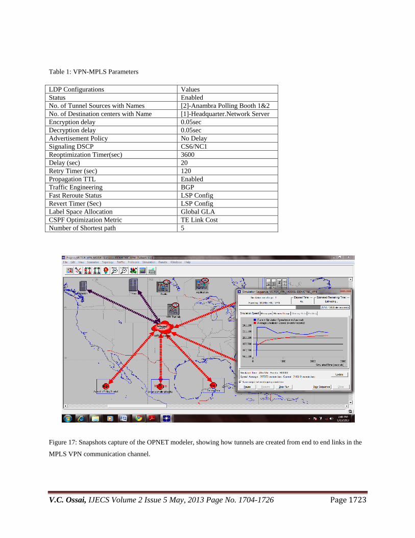
Figure 17: Snapshots capture of the OPNET modeler, showing how tunnels are created from end to end links in the
MPLS VPN communication channel.

V.C. Ossai, IJECS Volume 2 Issue 5 May, 2013 Page No. 1704-1726 Page 1724
Fig 17 above is a snapshot of the OPNET modeler during the run-time process. It is show the tunneling of
information across the VPN.
5.2 DISCUSSION OF RESULTS
OPNET was be used to evaluate the end to end latency between the polling modules and the collection centers, its
throughput, network stability and its network resource utilization. This formed the basis for validation since
biometric encryption has not been implemented in any E-voting model.
It is seen from the graphs in fig 18a, 18b, 18c, 18d; the MPLSVPN communication backbone for the
SMARESiM had a low end to end latency, high throughput, high stability margin and efficient resource utilization
considering the design layout for deployment of the SMARESiM.
Fig18 a Avg.Resource Utilization Fig 18b Avg.Network Delay Response
Avg VPN Tunnel Resource Utilization Avg Network Delay Response

V.C. Ossai, IJECS Volume 2 Issue 5 May, 2013 Page No. 1704-1726 Page 1725
Fig 18c Avg.Network Stability Response Fig 18d Avg.Network Throughput Response
6. CONCLUSION
A simulation model of an e-voting system leveraging on Biometric Encryption vis-a-vis Biometric key Binding on
fingerprints for the proposed SMARESiM has been developed. An MPLS VPN backbone as its communication link
has been successfully adopted, characterized and simulated. The communication link has also been validated using
metrics like end to end latency, Throughput, Network Stability and Tunnel resource utilization. Worthy of mention
is the fact that Biometric Key Binding (BKB) has not yet been adopted in any E-voting systems.
REFERENCES
1. Shane, P. (2004) Democracy Online: The Prospects for Political Renewal through the Internet. New York:
Routledge
2. Cramer, R. Franklin M. Schoenmakers B. and Yung M. (2006) Multi-authority secret ballot elections with linear
work. In: Advances in Cryptology,EUROCRYPT'96, Lecture Notes in Computer Science, pp.72-83.
3. Oleg Murk,Electronic Voting Schemes, M.Sc term paper,2000
4.Ivan Damg_ard, Jens Groth and Gorm Salomonsen, The Theory and Implementation of an Electronic,Voting
System, July 31, 2002.
5. A. Fujioka, T. Okamoto & K. Otha: A practical secret voting scheme for large scale elections., Advances in
Cryptology - AusCrypt '92, pp.244-251.
6. Ohkubo and Abe: A Length-Invariant Hybrid Mix Proceedings of Asia Crypt 00, Springer Verlag LNCS.
7 Abe: Universally veri_able MIX net with veri_cation work independent of the number of MIX centers;
proceedings of EuroCrypt 98, Springer Verlag LNCS.
8. www.computer.org/security : Evaluating Electronic Voting Systems Equipped with Voter-Verified Paper
Records. IEEE Security & Privacy, 2008.
9. Indrajit Ray, Indrakshi Ray, Natarajan Narasimhamurthi, ―An Anonymous Electronic Voting Protocol for Voting
Over The Internet‖.
10. Adem Alpaslan ALTUN and Metin BĐLGĐN, ― Web based secure e-voting system with fingerprint
Authentication‖ In Scientific Research and Essays Vol. 6(12), pp. 2494-2500, 18 June, 2011
Available online at http://www.academicjournals.org/SRE.
11. J.L, Wayman, ―fundamentals of biometric authentication technologies‖ Int. Image geaphics, vol.1, no.1, pp. 93-
113, 2001.
12. G.J. Tomko, C. Soutar, and G.J. Schmidt. “Fingerprint controlled public key cryptographic system‖. U.S.Patent
5541994, July 30, 1996 (Priority date: Sept. 7, 1994).
Throughput Plot to headquarter Server Network Stability Response
V.C. Ossai, IJECS Volume 2 Issue 5 May, 2013 Page No. 1704-1726 Page 1726
13. Uludag U, Pankanti S, Prabhakar S, Jain AK: Biometric cryptosystems: issues and challenges. Proc IEEE 2004,
92(6):948 960.
14. C. Soutar, D. Roberge, S. A. Stojanov, R. Gilroy, and B. V. K. Vijaya Kumar.Biometric encryption using image
processing. In Proc. SPIE, Optical Security and Counterfeit Deterrence Techniques II, vol. 3314, pages 178{188,
1998.
15. C. Soutar. Biometric system security. Available at http://www.bioscrypt.com/assets/security soutar.pdf.
16. Cranor L. and Cytron R. (2007) Sensus: a security-conscious electronic polling system for the Internet. In:
Proceedings of the Thirtieth Hawaii International Conference on System Sciences, Vol.3, pp.561-570