Embed Size (px)
Citation preview
Catalog No. L52316
SMALL SCALE WASTE HEAT RECOVERY STUDY
SwRI® PN-18-15481
Prepared for the
Pipeline Research Council International, Inc.
Prepared by: Southwest Research Institute
Authors:
Melissa Wilcox Nathan Poerner
Publication Date: March 2011
ii
ACKNOWLEDGEMENTS
Prepared by
Melissa Wilcox Nathan Poerner Marybeth Nored Brandon Ridens Jason Gatewood Matthew Blieske Dennis Tweten
Tim Allison, Ph.D. Klaus Brun, Ph.D.
GMRC Research Report 2010
Industry Advisory Committee
G. Achterbosch, Gasunie Anders Johnson, El Paso Bill Betenson, Williams Bill Couch, El Paso Bob Amsberry, Williams Chris Kapp, Siemens Christian Chauvel, GDF Suez Curt Pedersen, TransCanada Dan Harris, Spectra Energy David Pell, Voith Doug Boyko, TransGas
C. Fletcher, Dresser-Rand Jan-Peter Nilsson, Camfil Farr Jennifer Klementis, Alliance Pipeline Jim Bowman, CSI Luke Cowell, Solar Turbines Michael Smith, Hoerbiger Michael Whelan, PRCI Paul Doucette, GE Peter Baron, Solar Turbines Terry White, PG&E William Elston, Wartsila
Pipeline Research Council International Catalog No. L52316
Copyright 2011 All Rights Reserved by Pipeline Research Council International, Inc.
PRCI Reports are published by Technical Toolboxes, Inc.
3801 Kirby Drive, Suite 520 Houston, Texas 77098 Tel: 713-630-0505 Fax: 713-630-0560 Email: [email protected]

Small Scale Waste Heat Recovery SwRI Project No. 18.15481 GMRC 2010 Research Page i
Table of Contents
1. Introduction ........................................................................................................................ 1 2. WHR Concepts .................................................................................................................. 1 3. Initial Analyses ................................................................................................................... 2 4. Ranking of WHR Concepts ................................................................................................. 3
4.1 Rank Matrix ............................................................................................................... 3 4.2 Matrix Ranking ........................................................................................................... 5 4.3 Company Ranking ..................................................................................................... 5
5. Detailed Analyses ............................................................................................................... 6 5.1 Fuel Gas Pre-Heating ................................................................................................ 8 5.2 Turbine Inlet Cooling ................................................................................................ 10 5.3 Pipeline Gas Cooling ............................................................................................... 12 5.4 Electricity Use at Station (with stacked Rankine cycle) ............................................ 16 5.5 Heat Storage (Thermal Energy Storage) .................................................................. 20
6. Conclusions and Recommendations ................................................................................ 26 7. References ....................................................................................................................... 27 8. Appendix A: Initial Analysis of WHR Concepts ................................................................. 31
8.1 CO2 Rankine Cycle for Electricity Generation from Waste Heat .............................. 31 8.2 Electricity Uses ........................................................................................................ 35 8.3 Environmental Cooling (Absorption and Adsorption Chillers) ................................... 38 8.4 Environmental Heating ............................................................................................ 41 8.5 Flare Improvement ................................................................................................... 43 8.6 Fuel Gas Pre-Heating .............................................................................................. 44 8.7 Pipeline Gas Pre- and Post- Cooling........................................................................ 46 8.8 Gas Drying .............................................................................................................. 49 8.9 Gas Treatment from Waste Heat ............................................................................. 52 8.10 Thermal Energy Storage to Provide Power for Gas Turbine Restart ........................ 56 8.11 Using Waste Heat to Power Industrial Processes .................................................... 59 8.12 Additional Inlet Air Treating ...................................................................................... 60 8.13 Natural Gas Reforming Pre-Heat ............................................................................. 64 8.14 Oil and Coolant Pre-Heating .................................................................................... 67 8.15 Production of Distilled Water from Waste Heat ........................................................ 70 8.16 Rankine Cycle for Added Station Gas Compression Power using Variable Speed
Electric Motor Drives ................................................................................................ 74 8.17 Thermoelectrics ....................................................................................................... 77 8.18 Engine Inlet Cooling ................................................................................................. 79
Small Scale Waste Heat Recovery SwRI Project No. 18.15481 GMRC 2010 Research Page ii
List of Figures
Figure 5-1. Heat Capacity of Various Fuels as a Function of Temperature .............................. 8Figure 5-2. Schematic for Fuel Gas Pre-Heating ...................................................................... 9Figure 5-3. Diagram illustrating Use of an Absorption Chiller for Pre-Cooling ......................... 11Figure 5-4. Schematic Application of Gas Pre-Cooling ........................................................... 12Figure 5-5. Schematic of Absorption Chiller Internals ............................................................. 13Figure 5-6. General Schematic for Using Generated Power at Station ................................... 17Figure 5-7. Stacked Rankine Cycle Concept Schematic for Parallel Compressor
Station Drives with Gas Turbine and IC Engine Waste Heat Streams ................. 19Figure 5-8. Block Diagram for Thermal Energy Storage System with Steam Turbine
Starter ................................................................................................................. 21Figure 5-9. Thermally Stratified Hot Liquid Tank [30] ............................................................. 23Figure 5-10. Thermal Storage Tank Foundation [31] ................................................................ 24Figure 5-11. Capital Costs of Various Energy Storage Methods with Efficiency and
Durability in Mind [35] .......................................................................................... 25Figure 8-1. Typical Rankine Cycle Diagram ........................................................................... 31Figure 8-2. Exhaust Rankine Cycle Schematic [37] ................................................................ 32Figure 8-3. Super Critical Rankine Cycle T-S Diagram [37] .................................................... 32Figure 8-4: General Schematic for Using Generated Power at Station ................................... 37Figure 8-5: General Schematic of an Absorption Chiller ......................................................... 38Figure 8-6: Schematic for Operation of an Adsorption Chiller ................................................. 39Figure 8-7: Schematic for Fuel Gas Pre-Heating .................................................................... 45Figure 8-8: Glycol Gas Drying Simplified Process Schematic ................................................ 49Figure 8-9: Desiccant Gas Drying Simplified Process Schematic ........................................... 50Figure 8-10. The Amine Extraction Process [51] ...................................................................... 53Figure 8-11. Claus Process to Generate Sulfur from Hydrogen Sulfide [49] ............................. 54Figure 8-12. Block Diagram for Thermal Energy Storage System ............................................ 57Figure 8-13. Capital Costs of Various Energy Storage Methods with Efficiency and
Durability in Mind [35] .......................................................................................... 58Figure 8-14. One Option for Using Waste Heat to Aid in Natural Gas Reforming ..................... 64Figure 8-15. Multi-Stage Flash Distillation Diagram [68] ........................................................... 72Figure 8-16. Comparison of Primary GT Pipeline Sites Using ORC Cycle (Optimized
ORC Recovered Power Available for Electric Motor Driven Compression Power Shown in Red) .......................................................................................... 75
Figure 8-17. Selection of Small and Mid-size EMD Reciprocating Compressor Units for Primary Gas Turbine Compressor Stations Using ORC ....................................... 75
Figure 8-18: Possible Installation of a Thermoelectric Generator (TEG) to Harvest Waste Heat ......................................................................................................... 77
Figure 8-19: Diagram Illustrating Use of an Absorption Chiller for Pre-Cooling ........................ 79

Small Scale Waste Heat Recovery SwRI Project No. 18.15481 GMRC 2010 Research Page iii
List of Tables
Table 4-1. Rank Matrix for WHR Concepts ............................................................................. 4Table 4-2. Summary of Project Committee Company Rankings of WHR Concepts ................ 6Table 5-1. Summary of Expected Implementation Time Frames of WHR Concepts
from Project Committee Companies ...................................................................... 7Table 5-2. Installation Costs ................................................................................................. 15Table 5-3. Equipment Electricity Requirements & Cost ......................................................... 15Table 5-4. Examples of Electricity Uses at Station [20 – 28] ................................................. 16Table 5-5. Assumed Waste Heat Streams at Compressor Station with (1) Solar Titan
130 GT/ Centrifugal Compressor and (1) CAT G3616 Engine driven Reciprocating Compressor .................................................................................. 18
Table 5-6. Thermodynamic Calculations for Cycle 1: Primary Heat ...................................... 19Table 5-7. Cycle 2 Streams for Calculation of Flow-Averaged Total Temperature ................ 20Table 5-8. Common Liquid Material for Sensible Heat Storage [32] ...................................... 22Table 5-9. Common Solid Material for Sensible Heat Storage [32] ....................................... 22Table 5-10. Thermal Storage System Cost 101 Bar Rankine Cycle and 7° C Oil-to-Salt
Heat Exchanger LMTD [31] ................................................................................. 25Table 8-1. Comparison of Power Output for Carbon Dioxide Transcritical and R123
Organic Rankine Cycles ...................................................................................... 33Table 8-2: Examples of Electricity Uses at Station [20 – 28] ................................................. 36Table 8-3. Sour Gas Data ..................................................................................................... 55Table 8-4. Wet Gas Data ...................................................................................................... 55

Small Scale Waste Heat Recovery SwRI Project No. 18.15481 GMRC 2010 Research Page 1
11.. IINNTTRROODDUUCCTTIIOONN Two important and current topics of interest for gas machinery operators are emissions and energy efficiency. Current climate change legislation is leaning towards reduced emissions and improvements in energy utilization efficiency, which has renewed the interest in Waste Heat Recovery (WHR) at pipeline stations. In the past, the focus of WHR has been on large-scale applications, with little attention paid to small-scale WHR systems. This project focuses on small scale WHR specifically at compressor stations and considers stations with both gas turbines and Internal Combustion (IC) engines.
This report is divided in several sections. First, the various WHR concepts considered in this effort are outlined. Then, initial analyses of 18 of these concepts are reviewed. This is followed by a ranking of the concepts by Southwest Research Institute® (SwRI) based on relevant factors and by project company participants. A detailed analysis of the top five concepts from the rankings is reviewed. Lastly, conclusions and recommendations for further development of the WHR concepts are summarized.
22.. WWHHRR CCOONNCCEEPPTTSS The objective of this project was to identify several small-scale WHR concepts. Since the majority of the effort in WHR has been on large-scale operations, identification of small-scale concepts required new ideas. Requirements and desired characteristics were outlined for the WHR concepts. These are detailed in the lists below.
• Works for gas turbines or IC engines
Required Characteristics
• Operable at a high turndown • Has cold start-up capabilities • Failure of system has to have little or no impact on station operation • Improves station efficiency or improves emissions • Passive to human control
• Integrated energy storage
Desired Characteristics
• Payback/ROI appealing • Inside the compressor station fence • Average to minimal capital expense
In order to facilitate the identification of small-scale concepts, several brainstorming sessions were held. The first brainstorming session was held with the project committee (comprised of industry representatives) at the Gas/Electric Partnership Conference in February 2010. This list of ideas generated at this brainstorming session was complemented with ideas developed at brainstorming meetings at SwRI. The result of these brainstorming sessions was a list of more than 20 WHR concepts (shown below). The concepts were divided into three groups based on how the waste heat would be used: thermal, electrical, and mechanical. Thermal indicates that the concept would be used for a heating or cooling application. The concepts in the electrical group will use the waste heat to generate electricity. Lastly, the mechanical group has concepts, which use the waste heat for mechanical action.

Small Scale Waste Heat Recovery SwRI Project No. 18.15481 GMRC 2010 Research Page 2
• Engine oil and coolant pre-heat
Thermal
• Turbine and engine inlet cooling • Pipeline gas pre- and post-cooling • De-icing inlet filters • Using humidification/ drying as inlet filtration • Flare improvements • Pre-heating and pre-cooling lines • Environmental heating and cooling • Thermal storage (starter with steam turbine) • Pre-heating fuel gas for combustion (dual system – heat exchanger and electric heater) • Co-locate station with industrial process (gas treatment using waste heat (sour gas,
drying), production of distilled water (commodity export), NG reforming using waste heat as pre-heat, crop drying, sheet rock plant, greenhouse, foundries)
• How to generate electrical power
Electrical
o Rankine cycle for added compression capability o Thermoelectrics o Electricity generation with CO2 Rankine cycle o Stacked Rankine cycles accepting different grade heat sources
• Use electrical power onsite for: o TSBA controls o Condition monitoring equipment o Rod load monitoring, dynamic P equipment o Lube oil pumping o Flow meters o Seal gas compressor
• Heating compressor valves to reduce stiction
Mechanical
• ORC shaft power augmentation/ starter combination (with hydraulic accumulation for starting)
• Valves powered by waste heat • Store high pressure refrigerant from Rankine cycle for starting
33.. IINNIITTIIAALL AANNAALLYYSSEESS Several WHR concepts were outlined above. The concepts which are italicized in the list are the concepts which were analyzed further. Eighteen concepts were analyzed further. In several of these concepts, many variations were considered. For example, in the environmental cooling concept, the use of both absorption and adsorption chillers were reviewed.
The first step was the initial analysis. Each concept was reviewed to determine the feasibility of the idea being brought from a conceptual state to commercial operation. In this analysis, a basic description of the WHR concept was outlined, the equipment required for the concept was described, high level cost considerations were estimated, how the concept would impact the

Small Scale Waste Heat Recovery SwRI Project No. 18.15481 GMRC 2010 Research Page 3
compressor station was considered, and the concept was ranked according to the rank matrix (see Section 4). The initial analyses for the 18 WHR concepts are included in Appendix A.
44.. RRAANNKKIINNGG OOFF WWHHRR CCOONNCCEEPPTTSS 4.1 Rank Matrix The WHR concepts analyzed were ranked based on several parameters. The purpose of this ranking was to provide an unbiased method to determine which WHR concepts would be the most beneficial to develop for compressor stations. The rank matrix that was developed to rank each concept is shown in Table 4-1. Each category in the rank matrix is listed below with a discussion on the category. It should be noted that a higher score indicates a more favorable option. For example, a ‘5’ is a better score than a ‘1’.
• Capital Cost: This is the initial purchase price of the equipment. Large scale WHR (such as installing 4-6MW Organic Rankine Cycle (ORC)) is expensive (several million dollars). It is preferred that the proposed concepts be less costly to implement than large scale WHR.
• TRL: The TRL is the Total Readiness Level. This is taken from the commercialization categorization that the United States Department of Energy (DOE) uses for new projects and concepts. This parameter is an indication of how much development is required for the concept. A lower TRL indicates that there is still a need for research and development before the product can be commercialized.
• Impact on Station (during a failure): It is desirable that any WHR concept will have little to no impact on the pipeline station if a component of the WHR system was to fail. However, many of the WHR concepts are integrated into the station operation and can affect the station if they do fail. Therefore, this category was included to account for failure impact in the comparison of the concepts.
• Payback (full load 50% of year): In every venture made by a for-profit company, it is important that the money spent to implement new technology provide a monetary benefit. Pipeline stations typically look for paybacks at a minimum of four to five years. Some of the WHR concepts, although good in a theoretical sense, may not have a payback due to the high cost to implement. This category provides a high score to those concepts with a faster rate of return.
• Maintenance: With every new machinery system, additional maintenance is required. This category accounts for how often and how much maintenance may be required when installing a new WHR concept.
• Reliability: Reliability is an important aspect to machinery installed at a pipeline station. Unreliable equipment leads to lower overall station performance, which is highly undesirable. For each concept, the reliability was determined by how often the WHR system would be expected to fail (every year, every five years, etc.). If the system requires new equipment that had not been developed or used before, then its reliability was considered to be unproven, which earned the lowest score.
• Operation/ Training: Some WHR concepts require new technical knowledge for the operators at the station. The equipment used for the concept is equipment that has not been used at a pipeline station before, such as a thermal storage system. In addition, some concepts may require more supervision for operation. This category accounts for any additional training, knowledge, or supervision required for the WHR concept that is not already used at the pipeline station.

Small Scale Waste Heat Recovery SwRI Project No. 18.15481 GMRC 2010 Research Page 4
Table 4-1. Rank Matrix for WHR Concepts
Criteria 1 2 3 4 5 Weight Factor Capital Cost ($/million Btu/hr)
Expensive > 100,000 > 10,000 > 1000 > 100 Cheap
> 10 10
TRL Just on paper Modeled Prototyped Pre-commercial Commercial 5
Impact on Station (during failure)
Station shutdown Reduced
Operation No Impact 10
Payback (full load 50% of year)
No revenue or cost avoidance
Less than 20 years
Less than ten years
Less than five years
Less than one year 7.5
Maintenance Weekly maintenance items
Major overhaul <2 yrs, Monthly maintenance items
Quarterly maintenance items
Yearly maintenance items
Major overhaul 15 yrs 1
Reliability Unproven, no experience
Failure rate < 1 year
Failure rate > 1 year
Failure rate > 5 years
Failure rate > 10 years 10
Operation/ Training 24/7 supervision
Off-site supervision required
Operator training required
None required 5
Permitting Long and expensive Long or
expensive No special requirements 1
Total station efficiency improvement
< 2.5% >2.5% >5% >7.5% >10% 5
Environmental Considerations
No emissions benefits
Virtual emissions benefit
Emissions reduction from existing levels
10
Auxiliary benefits (improve equipment life, etc.)
None An additional benefit More than 2 2.5

Small Scale Waste Heat Recovery SwRI Project No. 18.15481 GMRC 2010 Research Page 5
• Permitting: Since many of the WHR concepts present new systems that have not been used at pipeline stations before, additional permitting may be required. This category includes this consideration in the rankings.
• Total Station Efficiency Improvement: One of the key objectives for implementing new WHR systems is to achieve a higher operational efficiency. The efficiency improvement for each WHR concept was estimated and assigned a score based on the rank matrix.
• Environmental Considerations: Another important goal of the WHR concept was to reduce emissions from the station. This has a regulatory benefit that is important to operators. If the WHR concept reduces emissions from their current level, then the highest score is assigned to the concept. When stations improve their energy efficiency (have a lower overall emission per energy input into the station) but do not decrease the current levels of emission, this is considered a virtual emission. No emission benefit has the lowest score.
• Auxiliary Benefits (improve equipment life, etc.): This category is included to account for any additional benefits that may be realized by installing the WHR concept.
Some of the WHR ranking categories were considered more important than others. For instance, it is imperative that the equipment installed for the WHR concept be reliable, but it is not necessary for the permitting process to be short. Therefore, a weighting factor was applied to each category. The weighting factors are shown in the column on the right hand side of Table 4-1.
4.2 Matrix Ranking After the scores were applied to each concept using the rank matrix, the concepts were ranked against each other. The top ten from the rank matrix comparison are listed below.
1. Processed Gas Drying 2. Turbine Inlet Cooling 3. Fuel gas Pre-Heating 4. Electricity Use at Station (with Stacked Rankine Cycle) 5. Pipeline Gas Cooling 6. Heat Storage 7. Gas Treatment using Waste Heat 8. Thermoelectrics 9. Industrial Processes (co-locating) 10. Rankine Cycle for Added Compression
4.3 Company Ranking Once the top ten concepts had been identified, these concepts were sent to the project committee for their assessment. The project committee companies were asked to rank the top ten WHR concepts and provide an opinion as to whether these concepts would likely be implemented in the future. Table 4-2 shows the rankings of the nine companies, which provided feedback. Some of the companies did not follow the ranking format requested; therefore, the rankings in Table 4-2 are inconsistent. For instance, Company 5 provided a high, medium, low, and never ranking. A value of 1, 1.33, 6.67, and 10 were assigned to each of these rankings, respectively. Companies 8 and 9 did not provide rankings for all the concepts; therefore, each of the concepts not ranked was assigned the same ranking.
In order to determine the final ranking of the top ten concepts, an average (last column in Table 4-2) was taken of all the rankings (both matrix rank and company ranks). The final top five

Small Scale Waste Heat Recovery SwRI Project No. 18.15481 GMRC 2010 Research Page 6
concepts were fuel gas pre-heating, turbine inlet cooling, pipeline gas cooling, electricity use at the station (with stacked Rankine cycle), and process gas drying.
Table 4-2. Summary of Project Committee Company Rankings of WHR Concepts
WHR Concept Matrix Rank
Company Rank Average Rank Co.1 Co.2 Co.3 Co.4 Co.5 Co.6 Co.7 Co.8 Co.9
Fuel Gas Pre-Heating 3 4 4 2 2 1 2 3 5 2 2.80
Turbine Inlet Cooling 2 5 3 1 5 3.33 1 2 4 6 3.23
Pipeline Gas Cooling 5 9 2 4 1 3.33 5 1 3 3 3.63
Electricity Use at Station (Stacked Rankine)
4 10 1 5 4 6.67 9 4 2 1 4.67
Processed Gas Drying 1 7 5 9 9 10 3 5 5 4 5.80
Heat Storage 6 2 6 10 3 6.67 7 7 5 6 5.87 Rankine Cycle for Added Compression
10 3 10 3 6 6.67 8 8 1 6 6.17
Industrial Processes (co-locating)
9 6 9 6 10 3.33 6 6 5 6 6.63
Thermoelectrics 8 1 8 8 7 6.67 10 9 5 6 6.87 Gas Treatment using Waste Heat
7 8 7 7 8 10 4 10 5 5 7.10
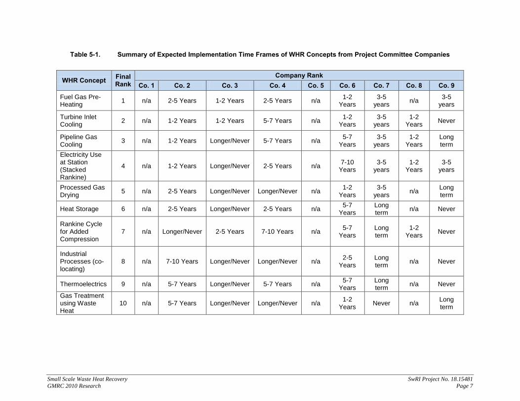
The companies also provided feedback on when they expect each of the top ten WHR concepts to be implemented. Table 5-1 shows the results of this survey. An n/a indicates that the company did not provide any information on this concept. The results of the survey indicates that the first concept (fuel gas pre-heating) is expected to be implemented in the next one to five years by all companies that responded. The majority of the companies that responded indicated that the second concept, turbine inlet cooling, would be implemented in one to two years. The next five concepts, pipeline gas cooling, electricity use at the station, process gas drying, heat storage, and Rankine cycle for added compression, had mixed reviews, with some companies indicating the concepts would be implemented in one to five years, and others suggesting, they would never be implemented. The majority of the companies indicated that the last three concepts, industrial processes (co-locating), thermoelectrics, and gas treatment using waste heat would never be implemented.
55.. DDEETTAAIILLEEDD AANNAALLYYSSEESS After the rankings were complete, the top five concepts were analyzed further. The top five concepts selected for analysis were those selected based on the rankings received by December 1, 2010. At that time, the top five concepts were fuel gas pre-hating, turbine inlet cooling, pipeline gas cooling, electricity use at the station (with stacked Rankine cycle), and heat storage. The detailed analyses of each of these concepts are provided in the following sections of this report.
Small Scale Waste Heat Recovery SwRI Project No. 18.15481 GMRC 2010 Research Page 7
Table 5-1. Summary of Expected Implementation Time Frames of WHR Concepts from Project Committee Companies
WHR Concept Final Rank
Company Rank Co. 1 Co. 2 Co. 3 Co. 4 Co. 5 Co. 6 Co. 7 Co. 8 Co. 9
Fuel Gas Pre-Heating 1 n/a 2-5 Years 1-2 Years 2-5 Years n/a 1-2
Years 3-5
years n/a 3-5 years
Turbine Inlet Cooling 2 n/a 1-2 Years 1-2 Years 5-7 Years n/a 1-2
Years 3-5
years 1-2
Years Never
Pipeline Gas Cooling 3 n/a 1-2 Years Longer/Never 5-7 Years n/a 5-7
Years 3-5
years 1-2
Years Long term
Electricity Use at Station (Stacked Rankine)
4 n/a 1-2 Years Longer/Never 2-5 Years n/a 7-10 Years
3-5 years
1-2 Years
3-5 years
Processed Gas Drying 5 n/a 2-5 Years Longer/Never Longer/Never n/a 1-2
Years 3-5
years n/a Long term
Heat Storage 6 n/a 2-5 Years Longer/Never 2-5 Years n/a 5-7 Years
Long term n/a Never
Rankine Cycle for Added Compression
7 n/a Longer/Never 2-5 Years 7-10 Years n/a 5-7 Years
Long term
1-2 Years Never
Industrial Processes (co-locating)
8 n/a 7-10 Years Longer/Never Longer/Never n/a 2-5 Years
Long term n/a Never
Thermoelectrics 9 n/a 5-7 Years Longer/Never 5-7 Years n/a 5-7 Years
Long term n/a Never
Gas Treatment using Waste Heat
10 n/a 5-7 Years Longer/Never Longer/Never n/a 1-2 Years Never n/a Long
term

Small Scale Waste Heat Recovery SwRI Project No. 18.15481 GMRC 2010 Research Page 8
5.1 Fuel Gas Pre-Heating 5.1.1 Description
The waste heat from a gas turbine exhaust stream can be used to preheat combustion fuel with three notable benefits; 1) avoidance of damaging liquid dropout in the fuel supply, 2) extension of the lean operating limit, and 3) increased efficiency. Avoidance of liquid dropout is of primary concern since it can directly prevent machine damage and help eliminate costly unplanned downtime.
Depending on the fuel gas used and the local environmental conditions, it is possible that condensates (water or hydrocarbons) can form prior to injection into a gas turbine. If these condensates are not removed prior to injection into a gas turbine, serious catastrophic damage can occur [1]. To deal with this issue, either a filter/ separation system can be placed in the fuel supply line, or the fuel gas can be heated to keep the temperature above the gas dew point. The second option, fuel gas heating, could be adapted to utilize waste heat from a gas turbine exhaust stream. This benefit is considered quite advantages as it could help prevent serious machine damage.
Preheating fuel gas can also function to increase operating flexibility by extending the lean operating limit and efficiency of a gas turbine. Heating of fuel gas essentially adds usable energy to the particles making up the gas which can be recovered during the combustion process. This improves overall operating efficiency, but also allows extension of the lean combustion limits of an air/fuel mixture since the fuel gas content has additional energy available at the higher temperature. As shown in Figure 5-1, the heat capacity increase of natural gas as a function of temperature is more pronounced than many other combustion fuels.
Figure 5-1. Heat Capacity of Various Fuels as a Function of Temperature

Small Scale Waste Heat Recovery SwRI Project No. 18.15481 GMRC 2010 Research Page 9
5.1.2 Equipment Requirements
An application of waste heat recovery should use a set of heat exchangers with an intermediate thermal fluid for transfer of the thermal energy, resulting in a system similar to what is shown in Figure 5-2.
Figure 5-2. Schematic for Fuel Gas Pre-Heating
This use of waste heat also has some added benefits. For one, this setup is very similar in concept to a regenerator, a well established method for improving overall turbine efficiency. Also, because the fuel gas would be at a higher temperature going into the gas turbine, it will be easier to ignite. However, this could also lead to pre-ignition. Therefore, the amount of heat transfer from the exhaust stream to the fuel gas needs to be regulated to ensure the temperature does not get close to the auto-ignition temperature (400° F to 550° F [2]) for the heavy liquid components of the fuel.
In instances where the unit is not running or the heat exchanging system fails (so that no waste heat is available), a heater will be necessary to provide the required temperature increase of the fuel gas (if this is necessary).
Additionally, modifications to the gas turbine combustion chamber may be needed to ensure optimized combustion characteristics. The combustion section of a gas turbine is designed to consider an anticipated range of parameters such as mixing length, ignition delay time, airflow, and flame propagation speed, and flame front oscillation frequencies. Significantly modifying the fuel gas temperature may require combustor modifications to accommodate changes to these design parameters. Lastly, all OEMs have temperature limits on the fuel systems. Design modifications may be necessary in order to accommodate the higher fuel temperature.
5.1.3 Cost Analysis:
Since the primary benefit of this application of waste heat is to prevent failure of a gas turbine, there is no realized capital benefit from this use. However, there is a return on the investment of the heat exchanger system because of the savings in electricity that would normally be used for the heating and from the possible beneficial increase of the unit efficiency.

Small Scale Waste Heat Recovery SwRI Project No. 18.15481 GMRC 2010 Research Page 10
Assuming a small gas turbine unit of approximately 1,600 HP, the following cost savings were calculated. The electricity savings to heat a natural gas fuel stream from its dew point to approximately 50° F higher would take about 7.5 kW; therefore, a unit that runs 50% of the year would garner a savings of about $3,000 by using waste heat instead of electricity. If the gas was heated higher, to a level of about 365° F [3], to improve the performance of the gas turbine, a fuel cost savings could be in the range of approximately $8,000 per year; using electricity for this temperature increase would cost about $19,000, which would not yield a positive return. By using the waste heat of the gas turbine, a minor cost savings can be obtained if the fuel gas is heated to a minimum level; but an alternate method for efficiency improvement is made possible that would increase cost savings by reducing fuel cost in addition to electricity (yields a total of about $11,000 total savings annually). Actual efficiency improvements and overall savings will be dependent on the system [4].
As discussed above, the direct economic advantage of fuel gas heating is manifest through small improvements in efficiency. However, when the reduced risk of failure and unplanned downtime are considered, the economic advantage can be considerable, although hard to estimate. The primary costs associated with fuel gas heating are capital cost associated with initial installation. These costs can be determined by sizing heat exchangers to match anticipated fuel gas flow rates and temperatures expected. Heat exchangers must be large enough to accommodate the anticipated mass flow and caloric contents of the fuel gas anticipated for the given gas turbine. For example, a gas turbine capable of producing about 35,000 horsepower may require a fuel flow rate of approximately 250 lb/sec of fuel with an LHV of about 23,000 btu/lbm depending on the actual gas composition. For this arrangement, gas turbine exhaust temperature may be in the range of 700 to 900° F. The cost of the heat exchanger that is required to deliver enough energy to heat the fuel gas will strongly depend on the amount of temperature change necessary to avoid liquid dropout. Therefore, significant design criteria are needed to define the capability and cost of a heat exchanger to be used for the purpose of fuel gas preheating.
5.2 Turbine Inlet Cooling 5.2.1 Description:
In efforts to increase engine power output when at maximum loads and improve engine efficiency, cooling of the air going into the inlet of a gas turbine is one possibility. Depending on engine design and original conditions, it is theoretically possible to increase the power output (if additional power is needed) which improves overall efficiency, resulting in savings on overall fuel costs. However, these savings can be quickly diminished by using cooling sources that rely on additional energy costs.
Instead, it is possible to use waste heat to perform cooling of the inlet air by using an absorption chiller, or similar type of technology.
5.2.2 Equipment Requirements:
Although there are numerous specific application scenarios, the general concept of using the waste heat from a turbine to perform pre-inlet air cooling is shown in Figure 5-3.

Small Scale Waste Heat Recovery SwRI Project No. 18.15481 GMRC 2010 Research Page 11
Figure 5-3. Diagram illustrating Use of an Absorption Chiller for Pre-Cooling
In this specific scenario, a heat exchanger is used to take heat from the exhaust gas and transfer it to an absorption chiller by way of a thermal fluid. Through the internal process of the absorption chiller this heat is used to cool a second thermal fluid, which is used in a second heat exchanger to cool the ambient air before its entry into the inlet of the gas turbine. Therefore, this scenario would require an absorption chiller system, two heat exchangers, and all of the necessary secondary equipment for fluid transfer (piping, pumps, etc.).
Implementation of this concept would require that the unit be shut down, and depending on the specifics of the chiller, some additional safety precautions might be necessary, and additional maintenance will be required. Should the chilling unit fail, the unit will still be able operate, just not at the higher efficiency.
5.2.3 Cost Analysis:
The cost of such a system is difficult to develop because the absorption chiller and heat exchangers really need to be designed for the specific turbine it will be implemented on. The same is also true in determining the cost savings. However, assuming theoretical operation for a 1,600 hp gas turbine, it was calculated that by dropping the inlet temperature by 20° F (from 90° F to 70° F, which is attainable for most any unit by using its exhaust heat energy), an efficiency improvement of just over 1% was attainable, which would result in approximately
Small Scale Waste Heat Recovery SwRI Project No. 18.15481 GMRC 2010 Research Page 12
$11,000 fuel savings per year. This amount of cooling for this unit would take approximately 25 TR (tons of refrigeration), and an absorption chilling unit that is capable of 30 TR would cost in the range of $35,000. Depending on the design of the turbine and original operating conditions, actual efficiency improvement and savings could vary drastically. So application of this waste heat recovery method would have to be judged on an individual unit basis [5-11].
5.3 Pipeline Gas Cooling 5.3.1 Description
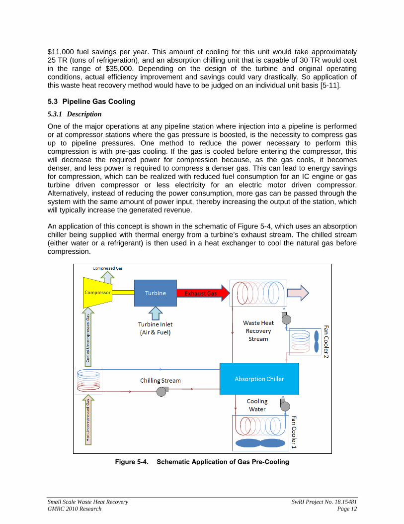
One of the major operations at any pipeline station where injection into a pipeline is performed or at compressor stations where the gas pressure is boosted, is the necessity to compress gas up to pipeline pressures. One method to reduce the power necessary to perform this compression is with pre-gas cooling. If the gas is cooled before entering the compressor, this will decrease the required power for compression because, as the gas cools, it becomes denser, and less power is required to compress a denser gas. This can lead to energy savings for compression, which can be realized with reduced fuel consumption for an IC engine or gas turbine driven compressor or less electricity for an electric motor driven compressor. Alternatively, instead of reducing the power consumption, more gas can be passed through the system with the same amount of power input, thereby increasing the output of the station, which will typically increase the generated revenue.
An application of this concept is shown in the schematic of Figure 5-4, which uses an absorption chiller being supplied with thermal energy from a turbine’s exhaust stream. The chilled stream (either water or a refrigerant) is then used in a heat exchanger to cool the natural gas before compression.
Figure 5-4. Schematic Application of Gas Pre-Cooling

Small Scale Waste Heat Recovery SwRI Project No. 18.15481 GMRC 2010 Research Page 13
Internal to the absorption chiller, the waste heat is used to create a chilled stream of water as shown in the schematic of Figure 5-5. This is just one type of absorption chiller which uses a mixture of ammonia and water. In addition to the input of heat, recovered from the exhaust stream, cooling water must also be supplied as well as a minimal amount of electricity to run the pump and control circuitry. The additional cooling water is used for the condensing operation and to remove any excess heat from the cycle.
Figure 5-5. Schematic of Absorption Chiller Internals
5.3.2 Equipment Requirements:
The specific application design of the system can vary greatly depending on what is available. For the purposes of this investigation, a system design as shown in Figure 5-4 will be analyzed. The turbine will be assumed to be a packaged Solar C40 compressor. The compressor requires approximately 6,800 hp, and so the turbine should have in excess of 25 MMBTUH of available exhaust energy. The goal in this application will be to reduce the temperature of the inlet natural gas, flowing at between 210-220 lbm/s, from 100° F to 90° F [12].
The largest required component in this overall schematic is the absorption chiller, which can be found from numerous manufacturers in fully packaged assemblies. One possible manufacturer is Trane, which offers numerous designs of single and two-stage absorption chillers to fit the specific needs of the station design. It is also possible, to find absorption chillers that can make use of either steam or hot water. To achieve the desired temperature drop of 10° F in this application requires a cooling load of nearly 325 TR, or almost 4 MMBTUH, which is possible with a York Single-Effect chiller model YIA-ST-4B4 from Johnson Controls (capable of 334 TR) [13]. In order to achieve this rate of cooling, the thermal heat input to the unit is nearly

Small Scale Waste Heat Recovery SwRI Project No. 18.15481 GMRC 2010 Research Page 14
6.5 MMBTUH. The electrical load of this size of absorption chiller is approximately 10 kW. The unit will then supply 44° F chilled water at a rate of nearly 810 GPM to be used by a heat exchanger to cool the natural gas. This heat exchanger can be designed and built by numerous manufacturers and can be one of a variety of types (such as shell & tube or plate exchangers).
Another required piece of equipment is the heat exchanger necessary to capture the required waste heat from the exhaust stream. As mentioned, the absorption chiller can make use of either hot water or steam, but for this investigation, a wastewater heater will be considered, in particular, a heat exchanger designed by Industrial Heat Transfer can be used to generate the necessary heat transfer rate to provide the heat to the absorption chiller. The flow rate will be obtained by using one of three required pumps. This unit is capable of generating hot water of nearly 250° F using just over 7 MMBTUH from the exhaust.
Because the water heater transfers more energy than needed by the absorption chiller, the water could need to undergo some additional cooling to remove the excess heat, which is the purpose of the “Fan Cooler 2” shown in the schematic of Figure 5-4, and would need to supply approximately 16 TR. An air-cooled dual-circuit chiller model #SA20D-4-2PT from Whaley Products, Inc., would fulfill this requirement with an electrical demand of near 75 kW. The dual circuit design would also allow for fine control of the cooling in case the chilling would vary depending on load [14].
The final major component required is another air-cooled water chiller to dissipate the heat from the absorption chiller’s cooling water (listed as “Fan Cooler 1” in Figure 5-4). The absorption chiller requires cooling water that is 85° F and supplied at a rate of 1,274 GPM. The water returned from the absorption chiller will be effectively 90° F, so the chiller must be able to supply nearly 210 TR, which can be achieved with a model #30RB225 unit from Carrier. This cooler requires an electrical demand of about 270 kW [15].
The remaining equipment requirements include the piping and pumps for each of the three fluid loops. For the most part, all of the piping should be insulated to reduce the amount of heat lost to the environment. The pumps will need to be sized for the specific application depending on pressure losses due to pipe lengths and the other fixtures in the respective lines. For this investigation, it will be assumed that each pump will require 50 kW of electricity to supply the necessary fluid flows and conditions.
5.3.3 Cost Analysis:
Starting with an initial inlet temperature of 100° F for a compressor working to compress natural gas from 800 psi to 1,100 psi at a standard flow of 400 mmscfd, a decrease in inlet temperature of 10° F could result in either using 171 hp less for mechanical power input to the compressor, if the same flow rate is maintained, or the power input could be held constant and the flow increased by about 10 mmscfd [12].
Assuming the cost of gas at between $3 and $6/mscf [16], if power is reduced to maintain the constant flow, fuel cost savings will be on the order of $5.5k to $11k per year (assuming 50% full-load uptime). Alternatively, if the power level is maintained, and the increased flow is selected, revenue could be increased. The actual return because of the increased throughput will be dependent on the station; whether it is the station of a producer that will get the $3 to $6/mscf of gas, or the station is that of a transport company, which will only get a fraction of that product cost. Also, the actual throughput will only increase if the point of this application was a bottle-neck for the entire system. Assuming that the location of this application was a bottle neck, and the station is a producer that gets the $3-$6/mscf of natural gas, the revenue for the
Small Scale Waste Heat Recovery SwRI Project No. 18.15481 GMRC 2010 Research Page 15
station will be increased by about $5.5 million to $11 million per year (again assuming 50% full-load uptime). On the other hand, a transport company might only see 6¢-60¢/mscf [17], and so the revenue increase for a transport company might only increase by $0.112 to $1.12 million per year.
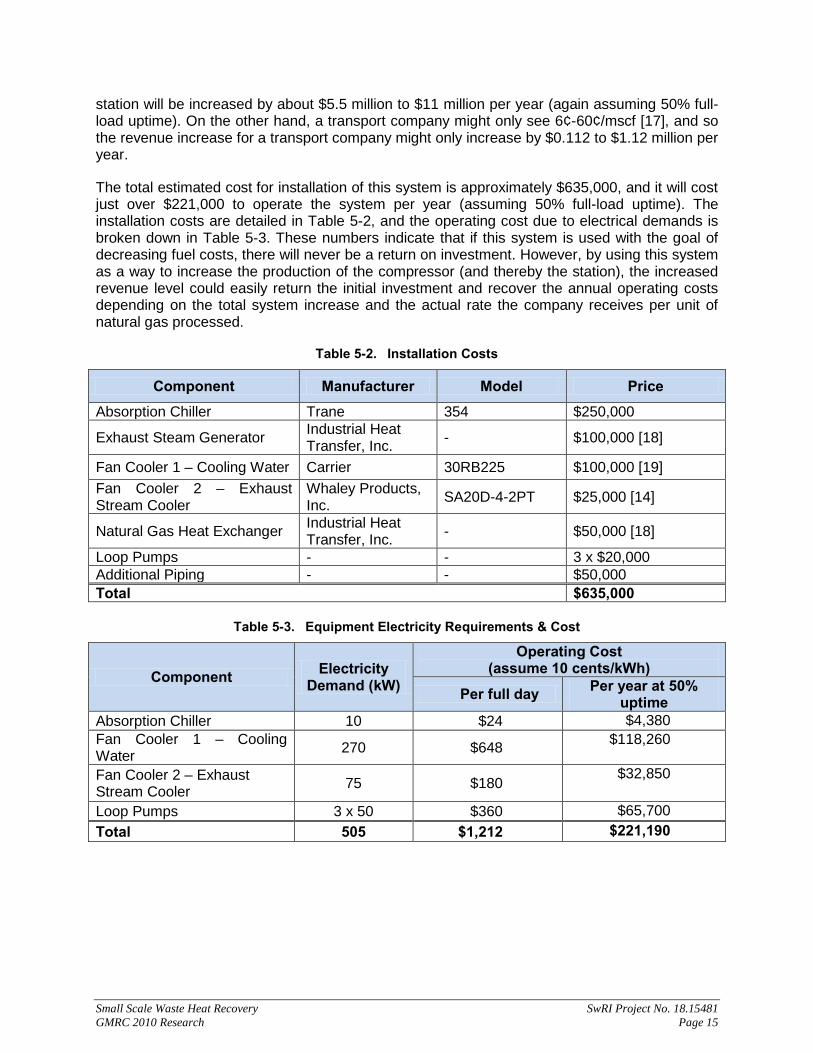
The total estimated cost for installation of this system is approximately $635,000, and it will cost just over $221,000 to operate the system per year (assuming 50% full-load uptime). The installation costs are detailed in Table 5-2, and the operating cost due to electrical demands is broken down in Table 5-3. These numbers indicate that if this system is used with the goal of decreasing fuel costs, there will never be a return on investment. However, by using this system as a way to increase the production of the compressor (and thereby the station), the increased revenue level could easily return the initial investment and recover the annual operating costs depending on the total system increase and the actual rate the company receives per unit of natural gas processed.
Table 5-2. Installation Costs
Component Manufacturer Model Price Absorption Chiller Trane 354 $250,000
Exhaust Steam Generator Industrial Heat Transfer, Inc. - $100,000 [18]
Fan Cooler 1 – Cooling Water Carrier 30RB225 $100,000 [19] Fan Cooler 2 – Exhaust Stream Cooler
Whaley Products, Inc. SA20D-4-2PT $25,000 [14]
Natural Gas Heat Exchanger Industrial Heat Transfer, Inc. - $50,000 [18]
Loop Pumps - - 3 x $20,000 Additional Piping - - $50,000 Total $635,000
Table 5-3. Equipment Electricity Requirements & Cost
Component Electricity Demand (kW)
Operating Cost (assume 10 cents/kWh)
Per full day Per year at 50% uptime
Absorption Chiller 10 $24 $4,380 Fan Cooler 1 – Cooling Water 270 $648 $118,260
Fan Cooler 2 – Exhaust Stream Cooler 75 $180 $32,850
Loop Pumps 3 x 50 $360 $65,700 Total 505 $1,212 $221,190

Small Scale Waste Heat Recovery SwRI Project No. 18.15481 GMRC 2010 Research Page 16
5.4 Electricity Use at Station (with stacked Rankine cycle) 5.4.1 Description:
5.4.1.1 Electricity Use
Ignoring the possibility of selling to a local power grid, many components at a station could make use of the electricity created from a waste heat process such as an ORC cycle. Some possibilities are listed in Table 5-4 below. Included in this table are: typical power requirements in kilowatts for each possible electricity-using component, the extent to which the specific component is used while the compressor unit is operational, and the annual cost of electricity that the component would likely use. The electricity use is assumed from a combination of the extent of use, an assumed total up-time for the station of 50%, and a cost of electricity of 10¢/kWh.
Table 5-4. Examples of Electricity Uses at Station [20 – 28]
Electricity Use Power
Required (kW)
Usable with:
Extent of Use
Annual Electricity Savings
(@ 10¢/kWh) TSBA controls (min) 1.200 GT, ICE Constant $ 525.60 (max) 1.560 GT, ICE Constant $ 683.28 Condition Monitoring Equipment 0.355 GT, ICE Constant $ 155.59 Rod Load Monitoring Equipment 0.055 GT, ICE Constant $ 24.09 Dynamic Pressure Equipment 0.051 GT, ICE Constant $ 22.17 Lube Oil Pumping (min) 93.000 GT, ICE Constant $ 40,734.00 (max) 187.000 GT, ICE Constant $ 81,906.00 Flow Meters 0.500 GT, ICE Constant $ 219.00 Cooling Fans (heat load of 6.4 MMBTUH) 300.000 GT, ICE Constant $ 131,400.00
Lighting (min at a 4.5 acre station) 23.300 GT, ICE Mostly in evening $ 5,102.70
(max at a 4.5 acre station) 38.100 GT, ICE Mostly in
evening $ 8,343.90
Air Conditioning (50 TR) 586.142 GT Hot times (summer) $ 128,365.13
Air Conditioning (150 TR) 1,758.427 GT Hot times (summer) $ 385,095.40
Environmental Heating 9.000 GT, ICE Cold times (winter) $ 1,314.00
SCADA (computer + transmitter) 0.550 Constant $ 240.90 Air Compressor - Pneumatics 372.856 GT Intermediate $ 65,324.38
Engine Pre-Heaters (avg) 30.000 GT, ICE Prior to unit start $ 2,628.00
5.4.1.2 Stacked Rankine Cycle
The stacked Rankine cycle is a method of creating inter-dependent heat recovery cycles, which are customized for the heat level and flow rates expected for each heat recovery stream at a compressor station. The concept exploits the multiple waste heat streams generated by a simple natural gas internal combustion engine where heat leaves the engine through the exhaust stack, the jacket cooling water and the after-cooler at varying levels. The method also

Small Scale Waste Heat Recovery SwRI Project No. 18.15481 GMRC 2010 Research Page 17
works well for a compressor station where a gas turbine driven compressor and engine driven compressor are used in parallel for gas compression.
5.4.2 Equipment Requirements:
5.4.2.1 Electricity Use
To enable use of the produced electricity (as an option to selling the electricity from an existing waste heat generation cycle), there would need to be a system that could distribute the produced electricity to the various components. Using the existing wiring is the most logical option. This would require equipment that would draw from the generated electricity first, a battery system second, and the local power grid as a backup, or a combination of the three sources. When the generated electricity is more than what can be used by the station, the system can divert the extra power to recharging the batteries. The general idea of the system layout is illustrated in Figure 5-6.
Figure 5-6. General Schematic for Using Generated Power at Station
If an electrical generation cycle is not already in place, additional requirements for equipment and installation will be necessary. This will drastically increase the initial cost of the system and further extend the payback period.
5.4.2.2 Stacked Rankine Cycle
In this evaluation, only two inter-dependent cycles are assumed: A primary power generation cycle and a secondary lower grade heat cycle. See Table 5-5 for assumed values of waste heat from a 15MW gas turbine drive and a 3.6 MW IC engine driver. The primary power cycle can be used for power needs of the secondary cycle (pumping, insulation and additional heat make-up for the steam generation). Figure 5-7 shows a schematic of the basic outputs from the gas compressor units and the WHR cycles.

Small Scale Waste Heat Recovery SwRI Project No. 18.15481 GMRC 2010 Research Page 18
Table 5-5. Assumed Waste Heat Streams at Compressor Station with (1) Solar Titan 130 GT/ Centrifugal Compressor and (1) CAT G3616 Engine driven Reciprocating Compressor
For the present thermodynamic analysis, the mass flow rates of the gas turbine and engine exhaust were combined, since they were available at similar temperatures. The total mass flow rate was approximately 194,000 kg/hour. Total heat output was estimated to be at 52 MW for this station, which was using approximately 19 MW of gas compression power. This post-combustion air product was assumed to flow through a heat exchanger to raise the temperature of a pentane/ ethane mixture, similar to organic Rankine cycle fluids. The organic fluid is pumped to 10 bar pressure prior to flowing through the heat exchanger. The fluid is then expanded to recovery approximately 6.3 MW. Allowing for losses and pumping power, the heat recovery cycle from the primary heat will generate 4.8 MW of additional electrical power or steam heat power – see Table 5-6 calculations.
The lower secondary heat cycle uses the waste heat in the organic fluid and non-recovered heat from the heat exchanger in cycle 1, combined with the jacket water heat and aftercooler heat streams from the engine. All of this waste heat can be converted to hot water or heat in the form of a secondary organic working fluid (see Table 5-7). The secondary cycle could be used for additional electrical power generation or other direct uses. (For example, steam or hot water could be used for co-location of the station near other industrial processes.) Other uses for low grade heat may be explored as well, to include combined solar power cycles or advanced “low-energy” phase change materials (such as pyrotechnic materials which can safely convert low heat sources to power). The present analysis shows that a water flow rate of 187,000 kg/hr could be used in the secondary cycle to raise the temperature to a working fluid temperature of approximately 106° C [5, 29].
Waste Heat Streams*Assume single station with one recip engine and one GT engine
Gas Turbine Exhaust (exhaust gas) *assume Solar Titan 130, 15 MWExhaust flow rate 179250 kg/hr mdot-1Temperature 495 degCDensity 0.542 kg/m3Enthalpy 980.88 kJ/kg
Engine exhaust 1 (exhaust gas) *assume CAT G3616 engine, 3.5-3.7 MWExhaust flow rate 13889.0 kg/hr mdot-2Temperature 461 degCDensity 0.5668 kg/m3Enthalpy 940.11 kJ/kg
Engine exhaust 2 (heat reject to jacket H20) *assume CAT G3616 engine, 3.5-3.7 MWExhaust flow rate 4618.8 kg/hr mdot-3Temperature 230 degCDensity 0.8274 kg/m3Enthalpy 677.32 kJ/kg
Engine exhaust 3 (aftercooler) *assume CAT G3616 engine, 3.5-3.7 MWExhaust flow rate 3150.4 kg/hr mdot-4Temperature 300 degCDensity 0.72622 kg/m3Enthalpy 754.2 kJ/kg

Small Scale Waste Heat Recovery SwRI Project No. 18.15481 GMRC 2010 Research Page 19
Figure 5-7. Stacked Rankine Cycle Concept Schematic for Parallel Compressor Station Drives
with Gas Turbine and IC Engine Waste Heat Streams
Table 5-6. Thermodynamic Calculations for Cycle 1: Primary Heat
GT Exhaust
IC engine Exhaust
Un-recovered Exhaust heat (UEH)
Secondary water or air heat exchanger for UEH
To cycle 2 boiler
Primary Heat Cycle for Power Generation
Secondary Heat Cycle for Steam
Power
ORG fluid pump
Water pump
Multiple HX
EXH to ORG fluid HX
Boiler
Added makeup heat (as
necessary) Steam expander or other
steam use
ORG fluid expander
Electrical Power out
Jacket cooling H20
After cooler WH
WH at 150-350 degC
WH at 450-500 degC
Cycle 1: ORG fluidTemperature Pressure Density Enthalpy Entropy
(°C) (bar) (kg/m³) (kJ/kg) (kJ/kg-K)Exit pump, enter heat exch 50 10 583.38 191.52 0.67855Leave heat exch, enter expander 283.32 10 10.48 1062.9 2.7802Ideal expansion 224.21 1 1.6553 918.01 2.7802Exit expander, water cooler inlet 230 1 1.6358 932.71 2.8096Water cooler out, pump inlet 45 1 2.6583 530.36 1.8261Expander efficiency = 89.854 %ORG fluid power out = 6328.681 kWPump efficiency (assume) = 90.000 %Pumping power = 1500.00 kWNet power out = 4828.68 kWHeat rejection to water = 402 kJ/kgEnthalpy, water out = 527.35 kJ/kg *assume air enters at 30degC and atm pressureTemperature, water out = 99.6 degC

Small Scale Waste Heat Recovery SwRI Project No. 18.15481 GMRC 2010 Research Page 20
Table 5-7. Cycle 2 Streams for Calculation of Flow-Averaged Total Temperature
5.4.3 Cost Analysis
The actual savings that are possible will be dependent on the type of components at the station, quantity of the components, and how much generated electricity is being produced at the facility. However, many of the possibilities shown in the table below indicate annual savings on the scale of $100k. The power control and battery systems could cost just as much, but that just indicates that the investment is recovered very quickly.
Assuming an ORC unit must be installed, or another similar technology to convert the waste heat to electricity, the only difference is the initial cost of the installation, which could be in the millions of dollars. As a result, the return will take far longer to recover the cost.
5.5 Heat Storage (Thermal Energy Storage) 5.5.1 Description of Idea:
Thermal Energy Storage (TES) is a technique that can be used to store energy in the form of heat. Heat can be stored in a liquid, gas, or solid medium. TES systems have been used in fields other than Oil and Gas Industry, most notably in solar power and HVAC systems. There are three methods for thermal energy storage systems: sensible heat storage, latent heat storage, and bond energy storage [30]. Sensible heat storage is energy stored in a solid or liquid by means of a temperature change without changing phase. Latent heat storage is energy stored in a liquid or solid by means of a phase change in the material. Bond energy storage, otherwise known as sorption heat, chemical heat, and reaction heat storage, is energy stored in a liquid, solid, or gas by means of shifting equilibrium points for a chemical reaction. The stored recovered heat (exhaust energy) can be used for many applications such as providing thermal energy for a steam turbine for startup situations [31].
When designing a TES system, some considerations must be made with regard to operating temperature range, energy storage capacity, duration of storage, cost, and rate of charge/ discharge [30]. Each of the three methods for storage outlined above has advantages and disadvantages. For example, latent heat (phase change) energy storage can be beneficial over
Cycle 2: Combined low heat streamsStream 1:water flow rate 180000 kg/hrwater temp 99.6 degCwater power in 20117.5 kWChange in ORG fluid enthalpy 413.85 kJ/kg changeStream 2:engine jacket water flow rate 4618.8 kg/hrwater temp 230 degCwater enthalpy 677.32 kJ/kgStream 3:engine aftercooler rate 3150.4 kg/hraftercooler temp 300 degCaftercooelr enthalpy 754.2 kJ/kgFlow rate of hot water = 187769.1 kg/hrHot steam / water temp = 106.170 degCHot steam / water temp = 379.170 degK

Small Scale Waste Heat Recovery SwRI Project No. 18.15481 GMRC 2010 Research Page 21
sensible heat energy storage, since the latent heat of fusion is generally a much higher value than an enthalpy change from 1 Kelvin [30]. Latent heat storage can also be beneficial due to its smaller size relative to the other methods. However, if cost considerations are important, then the sensible heat energy storage system would be a prime candidate. Many technical requirements for the TES need to be evaluated and conserved before and during the design process. They include choosing a storage material with a high energy density, the mechanical and chemical stability of the storage material, insuring low thermal losses, and ease of control [32]. Depending on the method of choice, considerations need to be made for providing sufficient heat transfer between the heat transfer fluid (HTF) and the storage medium, chemical compatibility between the HTF, heat exchanger and/or storage medium, and complete reversibility for a large number of charging/discharging cycles [32].
5.5.2 Equipment Requirements:
There are three primary components required for a TES system; a waste heat capture system, a heat exchanger to transfer used energy to a storage medium, and (a) storage tank(s) for the storage medium. A system to capture the waste heat and transport it to the TES system is required. In some cases, this system can be a part of the TES system itself. If a sensible heat storage system is chosen with water as the storage medium, then water can be pumped through a heat exchanger to capture the waste heat from the gas turbine. When using other methods or mediums, a separate system is usually required to capture the waste heat and is transferred to the storage medium through a heat exchanger. Furthermore, depending on the thermal energy storage capability (ρCp) of the medium, a significant amount of space may be required for the medium to be stored. An alternative to a storage tank is to use underground storage that can utilize existing aquifers but this limits the medium to water only [30]. This technology uses a natural underground layer (e.g. a sand, sandstone, or chalk layer) as a storage medium [33]. Extensive space requirements are also needed for an underground storage unless the design and construction of the TES are done in conjunction with the facility so that space accommodations may be made. Other technologies for underground TES are borehole storage, cavern storage and pit storage. Selection of these technologies strongly depends on the local geological conditions [33].
A block diagram for the system where the stored heat is used for a steam turbine starter is shown in Figure 5-8.
Figure 5-8. Block Diagram for Thermal Energy Storage System with Steam Turbine Starter

Small Scale Waste Heat Recovery SwRI Project No. 18.15481 GMRC 2010 Research Page 22
5.5.3 Design Considerations:
One factor that must be considered for each of the three storage methods is the selection of the storage medium. It is important for the material to have a high heat capacity (ρCp) value to maximize the amount of energy that can be stored. Some common materials used to store thermal energy are: water, organic liquids, molten salts, liquid metals, nitrides, chlorides, hydroxides, carbonates, and fluorides. Water is restricted in that, if used at atmospheric pressure, the storage temperature is limited to 100° C. Heat transfer oils are used in sensible heat storage system to intermediate temperatures ranging from 100 to 300° C [30]. When choosing a liquid material for a storage medium, molten inorganic salts are preferable due to the high maximum temperature they can hold and relatively high average heat conductivity. Table 5-8 provides a short list of common liquid storage materials available.
Table 5-8. Common Liquid Material for Sensible Heat Storage [32]
Energy can also be stored in solid media such as rocks or pebbles packed in insulated vessels. This type of storage is often used for temperatures up to 100° C, is simple in design, and relatively inexpensive. Larger amounts of solid are needed to equate liquid materials, such as water, due to the fact that solids, in general, exhibit a lower storing capacity than water [30]. Table 5-9 provides a short list of common solid storage materials available.
Table 5-9. Common Solid Material for Sensible Heat Storage [32]
Depending on the energy storage medium chosen; a design may have to incorporate a vessel that can withstand corrosion, extreme temperatures, and/or high pressures. Another important factor for each method for the storage unit is heat loss. Storage materials with relatively low heat conductivity are desired to minimize heat and energy loss [33]. Specifications of materials that can be used as storage vessels/ containers are provided in Table 5-9. One way to improve

Small Scale Waste Heat Recovery SwRI Project No. 18.15481 GMRC 2010 Research Page 23
the TES is by thermal stratification; the act of extracting higher temperature storage medium or heat from the top of the storage container and drawing cooler medium from the bottom to use for short isolation periods. The use of thermal stratification could improve efficiency, satisfaction, and performance in ideal situations [30]. Figure 5-9 demonstrates one example of a vessel that exhibits thermal stratification. To minimize energy loss to the atmosphere through the container walls, proper insulation can be a significant source of prevention. Some TES systems use insulation on the order of 8-in. thick or more [30]. Insulation can be a significant cost, especially for systems that require a long duration for storage or require a storage temperature significantly different from the ambient temperature. Many other factors contribute to the design of the TES. A standard storage tank weight is typically calculated from the following. The thickness of the wall at the bottom of the tank is calculated using the height of the tank, the density of the inventory fluid, the allowable material stress at the tank operating temperature, and conventional formulas for hoop stresses [31]. The wall thickness varies linearly from the bottom of the tank to the top with attribution to stress and temperature with a self-supporting dome roof [31]. Insulation thickness, often multiple layers, also varies linearly with the tank design temperature (e.g. increasing from a minimum of 300 mm to a maximum of 500 mm with a temperature range of 290° C to 565° C when using calcium silicate block insulation). The tank foundation takes great attention to insulation and isolation and the perimeter insulation is designed for safety factors and support. An example of a thermal tank foundation is shown in Figure 5-10.
Figure 5-9. Thermally Stratified Hot Liquid Tank [30]
Considerations must also be made for the inverse relationship between the surface area and cost of the heat exchanger and the quality and cost of the storage inventory when choosing a heat exchanger [31].

Small Scale Waste Heat Recovery SwRI Project No. 18.15481 GMRC 2010 Research Page 24
Figure 5-10. Thermal Storage Tank Foundation [31]
5.5.4 Cost Considerations:
Costs for each design element (storage material, heat exchanger, space, and enclosure) vary significantly between types and materials [32]. It is important to consider costs along with quality and purpose. For example, it would be potentially better to use nitrate salts as thermal storage material instead of water or mineral oil because of higher conductivity, even though the latter is more cost effective (see Table 5-8). Media costs per kg can be seen in Table 5-8 and Table 5-9 of common materials used in TES systems. A study done in 2004 found many unit costs for equipment, manufacturing, and labor for the various elements [31]. For the process of melting salt (if using salts as the storage material), an additional $0.02/kg was included to the price of the material in addition to $0.05/kg for labor and $0.50/kg installation cost. The unit price for carbon steel tanks, including material, shop fabrication, shipping, and field fabrication, was estimated to be $4.40/kg. Unit costs for insulation rise linearly with the thickness. It was estimated that the unit costs of calcium silicate block insulation with a corrugated aluminum jack cover would have a range of $160/m2 at a thickness of 300 mm to $235/m2 at a thickness of 500 mm. Subcontract unit prices for foam glass insulation were estimated to be $356/m3, and firebricks were found to be and estimated $1 each. If a concrete slab is needed, the estimated unit price would be $85/m3 with reinforcing steel costs of $0.80/kg. In the case that the slab or foundation would need insulation, an estimated cost of $100/m3 was found for insulated concrete. The unit price for an oil-to-salt heat exchanger was estimated to be $146/m². Unit costs for a salt pump heat exchanger ranged from $14,720/kWe-0.4488 and $5,512/kWe-0.1845 [31]. Each element of the design must be chosen based on the user’s/ client’s specifications and budget. Based on the previous data, a total TES system unit cost breakdown for storage capacities of 2 to 12 hours is shown in Table 5-10 [31]. It is noted that this information is based on studied and predicted thermal power stations.

Small Scale Waste Heat Recovery SwRI Project No. 18.15481 GMRC 2010 Research Page 25
Table 5-10. Thermal Storage System Cost 101 Bar Rankine Cycle and 7° C Oil-to-Salt Heat Exchanger LMTD [31]
Although cost can vary a great deal and depends on size and type of TES system chosen, one company has listed a range of costs to be in the 1 to 10 million dollar range for construction of a TES system alone [34]. However, these TES systems are for industrial cooling applications so for a gas turbine (GT) restart applications, costs should be estimated to be lower than these. Considering all other types of energy storage, thermal energy storage is still one of the most cost effective methods of energy storage available given its robustness with respect to cycling energy into and out of the system as shown in Figure 5-11 [35]. MacCracken [36] suggests an average cost of roughly $100/btu-hr for industrial ice cooling. Assuming the same order of magnitude for this TES system, a system could cost on the order of $10k+ for a standard 20,000 hp GT TES system.
Figure 5-11. Capital Costs of Various Energy Storage Methods with Efficiency and Durability in
Mind [35]

Small Scale Waste Heat Recovery SwRI Project No. 18.15481 GMRC 2010 Research Page 26
66.. CCOONNCCLLUUSSIIOONNSS AANNDD RREECCOOMMMMEENNDDAATTIIOONNSS This study has shown that there are several opportunities for the use of waste heat at a compressor station. Many of the concepts discussed in this report have been used in other applications or part of the concept has been implemented before, but not while using waste heat. Some of the other concepts are new ideas that have not been done and require a significant amount of development, before they can be implemented in the future. Out of the top ten concepts identified in this study, there are three main areas, which if developed further, have a high potential benefit to the station or could enable the use of many of the WHR concepts.
The first is the use of absorption chilling at the station. There are several processes that have been highlighted in this report that use absorption chilling to convert the waste heat from hot thermal energy to cold thermal energy. A few examples are pipeline gas cooling, gas turbine inlet cooling, environmental cooling, and engine oil cooling. Absorption chilling is a process that has been widely used in environmental cooling applications, and the chiller technology already exists. However, absorption chilling has not been used in applications at the pipeline station. This technology area would benefit from future work to characterize how the chilling process would perform at a station under the exhaust heat provided by a gas turbine, which often experiences variable loading.
The second area which would benefit from additional research is the development of the Stacked Rankine Cycle. The Organic Rankine Cycle has been widely used for applications where large amounts of low grade thermal energy exist. It has even been implemented in many compressor stations with gas turbines that operate at full load the majority of the year. However, this cycle is limited to applications where there is a large primary heat source. The Stacked Rankine Cycle takes advantage of multiple grades of heat, which makes it ideal for use at a station with an IC engine. IC engines typically have distributed heat sources (exhaust, oil, jacket cooling). This cycle is a new idea and has been reviewed at a high level in the current research effort. However, additional research is necessary in order to bring it to a prototype state.
The last area is heat storage. This technology has been used for applications in large buildings, but has not been applied in a pipeline station. The capability to store and use heat that is typically released into the atmosphere, could lead to a significant improvement in overall energy efficiency at a station. Many of the WHR concepts discussed use heat, but do not necessarily need the heat when it is generated. There are several areas of heat storage that need to be investigated: how long could the heat be stored, at what rate could the stored heat be released and how does that fit with WHR technologies that would use stored heat, and is there a cost and emissions benefit from storing the heat.

Small Scale Waste Heat Recovery SwRI Project No. 18.15481 GMRC 2010 Research Page 27
77.. RREEFFEERREENNCCEESS [1] EPRI, Fuel Composition Impacts on Combustion Turbine Operability. Palo Alto, CA :
EPRI, 2006. 1005035.
[2] Wilkes, Colin, Gas Fuel Clean-Up System Design Considerations. s.l. : GE Power Systems, 1996.
[3] Erickson, D. M., Day, S. A. and Doyle, R. Design Considerations for Heated Gas Fuel. Greenvile, SC : GE Power Systems, 2003
[4] Szargut, Jan, Energy and Exergy Analysis of the Preheating of Combustion Reactants, International Journal of Energy Research, Volume 12, Issue 1, Pages 45-58, 1988.
[5] Çengel, Yunus A. and Boles, Michael A. Thermodynamics: An Engineering Approach, 4th Ed. Boston: McGraw Hill, 2002, p. Chpt. 10.
[6] Colibri-BV. Colibri-BV: Documentation. Colibri-BV. [Online] [Cited: March 9, 2010.] http://www.colibri-bv.com/.
[7] DTE Energy. Absorption Chillers. [Online] March 2004. [Cited: March 9, 2010.] http://www.energytechpro.com/Demo-IC/Gas_Technology/Absorption_Chillers.htm.
[8] Power Partners, Inc., How ECO-MAX Chillers Work. [Online] 2010. [Cited: March 10, 2010.] http://www.eco-maxchillers.com/common/content.asp?PAGE=383.
[9] Patel, Piyush, Email Quote. s.l.: Thermax, Inc., March 10, 2010.
[10] West, Chris, Manager R&D. Email Quote. s.l., Berg Chilling Systems, Inc., March 11, 2010.
[11] Lopp, Tom, VP, Marketing. Email Quote. s.l. : Power Partners, Inc., March 10, 2010.
[12] Kurz, Rainer. Compressor Performance Calculations. July 2, 2009.
[13] Johnson Controls. York YIA Single-Effect Absorption Chillers Steam and Hot Water Chillers Style A {Product Literature}. Milwaukee, WI : Johnson Controls, 2008. Form: 155.16-EG1 (1008).
[14] Whaley, Jay. Email Quote with Product Information. s.l. : Whaley Produces, Inc., December 16, 2010.
[15] Carrier Corporation. Product Data: Aquasnap 30RB060-390 Air-Cooled Chillers. Syracuse, NY : Carrier Corporation, 2004. Catalog No. 523-077.
[16] Metal Prices. Natural Gas Prices and News. Metal Prices. [Online] [Cited: 12 20, 2010.] http://www.metalprices.com/FreeSite/metals/ng/ng.asp.
[17] Johnson, Anders. [Phone Conversation]. s.l. : El Paso Corporation, December 29, 2010.
[18] Newman, Nick. Email Quote and Product Information. s.l. : Industrial Heat Transfer, Inc., December 17, 2010.
[19] Cold Shot Chillers. Stationary Air Cooled Chiller Pricing. Cold Shot Chillers. [Online] 2010. [Cited: 12 13, 2010.] http://www.waterchillers.com/stationary-air-cooled-chillers-pricing.html.
[20] Watlow Electric Manufacturing Company. Circulation Heaters. Hannibal, MiI : Watlow Industries, 1999.
[21] Hudson Products. Preliminary Sizing and Price Estimate. 2008.

Small Scale Waste Heat Recovery SwRI Project No. 18.15481 GMRC 2010 Research Page 28
[22] Atlas Lighting Products. Features and Specifications: Flood Lighting (FLL16 Series). Burlington, NC : Atlas Lighting Products.
[23] Michaels, Joelle Davis. A Look at Office Buildings - Index. [Online] Energy Information Administration - DOE, January 3, 2001. [Cited: March 10, 2010.] http://www.eia.doe.gov/emeu/consumptionbriefs/cbecs/pbawebsite/office/office_contents.htm.
[24] McKenzie Compressed Air Solutions. Quincy QS2 PowerSync Rotary Air Compressor. McKenzie. [Online] [Cited: June 1, 2010.] http://www.mckenzieair.com/quincy-air-compressor-air-compressor-rotary-screw-powersync-qs2.asp.
[25] Buffalopumps. Lube Oil Pumps: Model E-VCRE Vertical Design for Low to Medium Oil Flows. North Tonawanda, NY : Buffalopumps.
[26] Joyce Linear Actuators. 1500 Pound AC with Limit Switch. s.l. : Joyce Dayton.
[27] Flow Line Options Corp. Ultrasonic Flow Meters, Transit Time, Doppler Flowmeters. Flo-Corp. [Online] [Cited: April 23, 2010.] http://www.flowlineoptions.com/flowmeters /ultrasonic .
[28] Flowmetrics, Inc. 923-ST1: Multi-Function Flow Totalizer, Ratemeter and Batcher. Chatsworth, CA : Flowmetrics, Inc., 2006.
[29] National Institue of Standards and Technology (NIST). Reference Fluid Thermodynamic and Transport Properties Database (REFPROP). [Software] Boulder, CO: s.n., 2010.
[30] Ataer, O. Ercan. “Storage of Thermal Energy, in Energy Storage Systems.” Encyclopedia of Life Support Systems (EOLSS), 2006.
[31] Kelly, B., and D. Kearney. “Thermal Storage Commercial Plant Design Study for a 2-Tank Indirect Molten Salt System.” Nexant, Inc., Kearney & Associates, National Renewable Energy Laboratory, July 2006.
[32] Herrmann, Ulf, Michael Geyer and Dave Kearney. “Overview on Thermal Storage Systems.” FLABeg Solar Int. GmbH, Kearney & Associates, Workshop on Thermal Storage for Through Power Systems, February 20-21, 2002.
[33] IEA ECES: http://www.iea-eces.org/energy-storage/storage-techniques/underground-thermal-energy-storage.html
[34] Goss Engineering: http://www.gossengineering.com/consulting_engineers_for_tes_ thermal_energy_storage_system_design.htm#TES Design and Study Projects
[35] MacCracken, Mark M. “Energy Storage: A Critical Path to Sustainability.” Process and Technology, Vol. 6, 2009.
[36] MacCracken, Mark M. “Thermal Energy Storage Myths.” American Society of Heating, Refrigerating and Air-conditioning Engineers (ASHRAE) Journal, September 2003.
[37] E. Auter, et al. “Optimum for CO2 Transcritical Rankine Cycle Using Exhaust Gas from Fishing Boat Diesel Engines”, Proceedings of the 2009 IFAC Workshop on Engine and Powertrain Control, 2009, pp. 132-139.
[38] http://www.eia.doe.gov/fuelelectric.html
[39] Elvidge, Chistopher D., et al., A Twelve Year Record of National and Global Gas Flaring Volumes Estimated Using Satellite Data. Boulder : NOAA National Geophysical Data Center, 2007.

Small Scale Waste Heat Recovery SwRI Project No. 18.15481 GMRC 2010 Research Page 29
[40] Mechanical Engineering Department, University of Alberta, Flare Research Project. [Online] July 30, 2001. [Cited: March 22, 2010.] http://www.mece.ualberta.ca/groups/ combustion/flare/index.html
[41] John Zink Company, LLC., John Zink: Upgrades and Retrofits. [Online] [Cited: March 22, 2010.] http://www.johnzink.com/parts/flares/html/ps_fl_up.htm
[42] Oilfield Production Equipment Ltd., OilPro - Tech Notes - Glycol, the un-Gatorade. OilPro. [Online] 2003. [Cited: May 17, 2010.] http://www.oilpro.ab.ca/tnGlycol.htm
[43] The Dow Chemical Company, Tetraethylene Glycol {Product Brochure}. s.l. : The Dow Chemical Company, 2007.
[44] Bry-Air, Dehumidifiers - VFB Industrial and Commercial Dehumidifiers. Bry-Air (USA) Dehumidification. [Online] Bry-Air, Inc., 2010. [Cited: May 17, 2010.] http://www.bry-air.com/products/vfb/default.html
[45] KW International, Glycol Dehydrators. KW International. [Online] KW Ineternational, 2008. [Cited: May 17, 2010.] http://kwintl.com/glycol-dehydrators.html#technical
[46] Primenergy LLC, Gas Conditions [Online] [Cited: May 17, 2010.] http://primenergy-production.com/gasconditioning.htm
[47] Natural Gas Supply Association, NaturalGas.org: Processing Natural Gas. NaturalGas.org. [Online] 2004. [Cited: May 17, 2010.] http://www.naturalgas. org/naturalgas/processing_ng.asp#water
[48] Natural Gas Dehydration: Lessons Learned from the Natural Gas STAR Program. ConocoPhillips, Durango, CO : Producers Technology Transfer Workshop, 2007.
[49] M. Sassi, et al. “Sulfur Recovery from Acid Gas Using the Claus Process and High Temperature Air Combustion (HiTAC) Technology”, American Journal of Environmental Sciences, Vol. 4(5), 2008, pp. 502-511.
[50] http://articles.compressionjobs.com/articles/oilfield-101/2711-gas-dehydration-lts-hydrates-sweetening-amine?start=3
[51] http://www.newpointgas.com/amine_treating.php
[52] http://www.neliott.demon.co.uk/company/claus.htm
[53] “Specialty Amine”, INEOS Gas/Spec.
[54] V. Hernandez-Valencia, et. all. “Design Glycol Units for Maximum Efficiency”, Bryan Research and Engineering, Inc. Technical Paper, 2006.
[55] “Triethylene Glycol”, Huntsman Technical Bulletin, 2008.
[56] “Crop Drying with Heat Pumps.” National Food and Energy Council
[57] Wikipedia.org. http://en.wikipedia.org/wiki/Calcination
[58] P. Rorabaugh, M. Jensen, and G. Giacomelli. Introduction to Controlled Environment Agriculture and Hydroponics. Pgs 13-1 and 13-4. University of Arizona.
[59] S. Stanford. Reducing Natural Gas / Propane use for Greenhouse Space Heating. University of Wisconsin.
[60] Wikipedia.org. http://en.wikipedia.org/wiki/Foundry
[61] Brooks, Frank J. GE Gas Turbine Performance Characteristics. Schenectady, NY : GE Power Systems, 2000.

Small Scale Waste Heat Recovery SwRI Project No. 18.15481 GMRC 2010 Research Page 30
[62] Inlet Fogging of Gas Turbine Engines - Part B: Practical Considerations, Control, and O&M Aspects. Meher-Homji, Cyrus B. and Mee, Thomas R. Munich : Proceedings of ASME Turbo Expo, 2000.
[63] US Department of Energy. FCT Hydrogen Production: Natural Gas Reforming. [Online] December 15, 2008. [Cited: March 11, 2010.] http://www1.eere.energy.gov/hydrogen andfuelcells/production/natural_gas.html
[64] http://www.water-technology.net/
[65] http://www.alfalaval.com/
[66] http://www.mecomarineoilandgas.com/
[67] Tennile Winter et al, August 14, 2008, “The Economics of Desalination and its Potential Application in Australia”, http://www.general.uwa.edu.au/u/dpannell/dpap0102.htm
[68] http://www.sidem-desalination.com/
[69] Sidem Entropie, “Multiple Effect Distillation Process for Sea Water Desalination”, Catalogue.
[70] http://www.saws.org/
[71] Recent 2010 PRCI report by SwRI on “Assessment of Adjustable Speed Drive Systems for Pipeline Pump Applications.”
[72] Hi-Z Technology, Inc., Thermoelectric Modules. Hi-Z Technology, Inc. [Online] [Cited: April 8, 2010.] http://www.hi-z.com/products.php
[73] Fleurial, J. P., et al., s.l., Waste Heat Recovery Opportunities for Thermoelectric Generators. : 2009 Thermoelectric Applications Workshop, 2009.

Small Scale Waste Heat Recovery SwRI Project No. 18.15481 GMRC 2010 Research Page 31
88.. AAPPPPEENNDDIIXX AA:: IINNIITTIIAALL AANNAALLYYSSIISS OOFF WWHHRR CCOONNCCEEPPTTSS 8.1 CO2 Rankine Cycle for Electricity Generation from Waste Heat 8.1.1 Description of Idea
The Rankine cycle is the ideal vapor power cycle for power plants and is used to convert a temperature gradient into mechanical/ electrical power [5]. The typical Rankine cycle uses water/ steam as the working fluid at high temperatures and pressures. Figure 8-1 shows the T-S diagram for a typical Rankine cycle. Figure 8-2 shows the schematic of a Rankine cycle applied to exhaust heat. The process begins with a saturated liquid at Point 1 at a lower pressure (see Figure 8-1). The pressure and temperature is increased isentropically with a pump to Point 2. Heat is then applied to the working fluid to convert the liquid into a saturated vapor as shown in Figure 8-1, or vapor/ super-critical vapor (Point 3). The vapor is then expanded through a turbine isentropically, creating mechanical power and reducing the pressure and temperature of the working fluid (Point 4). Finally, heat is removed from the vapor, condensing the fluid to a liquid once more and returning to Point 1. This process can employ water or an organic fluid such as R123. The organic Rankine cycle (ORC) is a Rankine cycle that occurs at temperatures much lower than those used for steam.
Figure 8-1. Typical Rankine Cycle Diagram
In order to use carbon dioxide as the working fluid, it has been proposed to use a modified transcritical Rankine cycle [37]. This process is outlined in Figure 8-3, which represents the same schematic in Figure 8-2. In a transcritical Rankine cycle, the process starts with the working fluid as a saturated liquid. It is then converted to a super-critical fluid isentropically via pump to Point 2. Heat is then added to the super-critical fluid to a larger pressure and temperature at Point 4 and then expanded to Point 4 through a turbine creating mechanical power. Finally, the super-critical vapor/ vapor at Point 4 is condensed to Point 1 to initiate the process once more. The temperatures for this transcritical Rankine cycle presented in Figure 8-3 indicate that when CO2 is used, the process is an ORC. The figure also demonstrates that with a critical temperature of 304 K (87° F), any practical implementation of CO2 as a working fluid must be transcritical.

Small Scale Waste Heat Recovery SwRI Project No. 18.15481 GMRC 2010 Research Page 32
Figure 8-2. Exhaust Rankine Cycle Schematic [37]
Figure 8-3. Super Critical Rankine Cycle T-S Diagram [37]
In an initial literature review, there were no claims that CO2 is a superior working fluid to organic refrigerants. However, there are several advantages to using CO2 over an organic refrigerant. The main advantage is that carbon dioxide is an inert gas that would have little impact on the environment if leaked [37]. Other refrigerants can deplete the ozone or have a much stronger global warming potential.
CCoooolliinngg ((CCoonnddeennsseerr))
3
4
3
4

Small Scale Waste Heat Recovery SwRI Project No. 18.15481 GMRC 2010 Research Page 33
A cursory analysis was performed to compare a transcritical CO2 system with R123, a currently available organic refrigerant. The application is an engine (~500 hp) typical of a fishing vessel [37]. The exhaust temperature was assumed to be 660° F at a rate of 1.36 lbm/s. The pump efficiency was assumed to be 0.8 and the expander (turbine) efficiency was assumed to be 0.7. Cross flow heat exchangers were assumed with a difference of about 9° F between exhaust gas inlet temperature and carbon dioxide outlet temperature. Three maximum pressures were assumed for carbon dioxide: 1,160 psi, 1,890 psi, and 2,900 psi. In order to implement a transcritical cycle, a minimum pressure of about 1,160 psi is required for carbon dioxide. Two maximum pressures were assumed for R123: 145 psi and 510 psi. In addition, the maximum temperature for R123 within the cycle was 620°F. Table 8-1 provides the comparison of power generated for both cycles at the various cycle operating conditions. Calculations based on the transcritical carbon dioxide cycle are taken directly from the paper [37], but the calculation at 1,890 psi was double-checked by SwRI. Power output values were calculated by SwRI using the identical procedure used for carbon dioxide, except that a typical Rankine cycle was assumed rather than a transcritical cycle.
Table 8-1. Comparison of Power Output for Carbon Dioxide Transcritical and R123 Organic Rankine Cycles
Carbon Dioxide R123 Peak Pressure [psi] Power Output [kW] Peak Pressure [psi] Power Output [kW]
1160 6.4 145 23.7 1890 18.4 510 32.0 2900 26.0
Table 8-1 above indicates that the total amount of power that can be produced by the carbon dioxide transcritical cycle is extremely dependent on the peak pressure of the cycle. In addition, pressures in such a cycle must be quite high to get power output equivalent to a traditional organic refrigerant such as R123. It should also be noted that the R123 case with a peak pressure of 510 psi is not likely to be realistic, as the critical pressure for R123 is about 530 psi. However, even at the much lower pressure of 145 psi, the R123 is nearly equivalent or out-performs carbon dioxide. The high pressures necessary for the carbon dioxide cycle is certainly a drawback to this concept, but not necessarily an insurmountable concern. It should be noted that the previous analysis does not include a regeneration element in the process, which tends to increase the efficiency of the cycle and therefore increases the overall energy output.
For the natural gas industry, the carbon dioxide transcritical organic Rankine cycle implemented as an energy harvesting device has the potential to exploit waste heat in exhaust gas for electrical power. Such electrical power could be used locally to run processes, light, and power buildings, or be sold and distributed on power grids. The process could be used for generating electricity from both reciprocating engines and gas turbines. However, the amount of energy that could be harvested from turbines may be limited by pressure allowable in the cycle.
8.1.2 Equipment Requirements
The basic equipment required to implement an energy harvester using the transcritical organic Rankine cycle includes a pump, a heat exchanger for the exhaust heat, a turbine to produce electricity, and a condenser with a cooling sink such as water or air. The biggest modification to existing sites would be to reroute the exhaust through a heat exchanger. Such lines from the exhaust would not be allowed to significantly interfere with the flow of the exhaust gas. Additional wiring would be required to transmit power from the energy harvesting device to other

Small Scale Waste Heat Recovery SwRI Project No. 18.15481 GMRC 2010 Research Page 34
buildings and processes. If the electricity is to be sold to a utility company, additional and expensive equipment such as substations may be required. Currently, no existing product that uses a carbon dioxide Rankine cycle is known to exist, and current research appears to be mostly at the theoretical stage. It could be many years until such technology is available.
8.1.3 Cost Considerations
The average cost of electricity in the United States is 9.74 cents per kilowatt hour [38]. For the small engine example in the previous section, the cost of electricity saved per hour using the CO2 Rankine cycle is about 2.53 cents or about 0.0051 cents per horsepower. This savings comes out to about $22,000 per year or about $44 per year per horse power. Extrapolating this rate to a 10,000 hp machine would generate about $220,000 per year. These calculations assume that a peak pressure of 2,900 psi can be achieved, that the machine would be running 24 hours for half of the year, that exhaust flow is directly proportional to hp, and that the electricity could be used or stored on site. Depending on the cost of the energy harvesting unit, the actual pressures used in the cycle, and number of hours run per year, payback on such a system could take anywhere from 6 to 20 years. An additional complication may be actually using the electricity generated. Based on the maximum output of a CO2 energy harvester, the equivalent increase in efficiency would be about 7%.
8.1.4 Impact on Station
Equipment used to implement this process would be located at engine and turbine exhaust locations and have a minimal impact on the operation compressor stations. If the energy harvesting equipment were to break down, normal operation of the compressor station could continue. However, if the compressor station were to be shut down, the energy harvesting equipment would no longer be able to produce electricity. If the electricity generated by the energy harvester is used for a critical application, shut down of the engine/ turbine could have a large impact on the critical machinery/process. It is expected that electricity could still be generated at a partial load; however, the amount of electricity produced would also be reduced. The pump in the Rankine cycle would likely have to be powered from a source other than the energy harvester itself, at least while the energy harvesting equipment is brought on line.
8.1.5 Scoring
Criteria Score Reasoning
Capital Cost 3 No product is currently available; however, the proposed application for such a device is for small engines.
TRL 1 Using a CO2 transcritical organic Rankine cycle appears to still be at a purely theoretical phase.
Impact on Station 5
Exhaust heat will be required for the energy harvester to operate, but it is expected that no impact on the station will occur if the energy harvester is to fail.
Payback 2 Payback is dependent on actual use of the generated electricity and therefore cost savings.
Maintenance 3 Pumps turbines and high pressure lines will all be added to the station.
Reliability 3 High pressure lines could be an issue.
Operation/ Training 3 Additional training may be required due to high pressure lines.

Small Scale Waste Heat Recovery SwRI Project No. 18.15481 GMRC 2010 Research Page 35
Criteria Score Reasoning Permitting 4 Not expected to be difficult to permit. Efficiency Improvement 3 Modest equivalent increase in efficiency of about
7%. Environmental 3 Creation of emission-free electricity Auxiliary Benefits 1 No auxiliary benefits expected. Weighted Average 2.98
8.2 Electricity Uses 8.2.1 Description
Ignoring the possibility of selling to a local power grid, many components at a station could make use of the electricity created from a waste heat process such as an ORC cycle. Table 8-2 lists some possibilities. Included in this table are typical power requirements in kilowatts for each possible electricity-using component. Also shown in this table is the extent to which the specific component is used while the compressor unit is operational and the annual cost of electricity that the component would likely use. The electricity use is assumed from a combination of the extent of use, an assumed total up-time for the station of 50%, and a cost of electricity of 10 ¢/kWh.
Whether the power requirement can be generated from the waste heat depends on the size of the unit and the generation cycle, but assumes an ORC cycle exists with a 13% efficiency that uses the average available waste heat for a gas turbine (about 23,000 hp) or an ICE (3,000 hp range), then the available electricity is nearly 3,500 kW from a gas turbine and 160 kW from an ICE. From this, it can be seen that there are some possible components that cannot be powered by the average ICE; however, all of these possible components could be powered from the waste heat of the average gas turbine.
For times when the components must be powered while the waste heat electricity is not available, either because the compressor unit is down or the generation cycle is inoperable, electricity could be drawn from a battery system that is charged by any excess waste heat electricity generated during normal operation or from alternate green energy (such as solar). For extended periods of downtime and for any power requirement above what can be produced, connection to a local power grid would be necessary.
8.2.2 Equipment Requirements
To enable use of the produced electricity (as an option to selling the electricity from an existing waste heat generation cycle), a system that could distribute the produced electricity to the various components is needed. Using the existing wiring is the most logical option. This would require equipment that would draw from the generated electricity first, a battery system second, and the local power grid as a backup, or a combination of the three sources. When the generated electricity is more than what can be used by the station, the system can divert the extra power to recharge the batteries. Figure 8-4 illustrates the general idea of the system layout.

Small Scale Waste Heat Recovery SwRI Project No. 18.15481 GMRC 2010 Research Page 36
Table 8-2: Examples of Electricity Uses at Station [20 – 28]
Electricity Use Power
Required (kW)
Usable with:
Extent of Use
Annual Electricity Savings
(@ 10¢/kWh) TSBA controls (min) 1.200 GT, ICE Constant $ 525.60 (max) 1.560 GT, ICE Constant $ 683.28
Condition Monitoring Equipment 0.355 GT, ICE Constant $ 155.59 Rod Load Monitoring Equipment 0.055 GT, ICE Constant $ 24.09 Dynamic Pressure Equipment 0.051 GT, ICE Constant $ 22.17
Lube Oil Pumping (min) 93.000 GT, ICE Constant $ 40,734.00 (max) 187.000 GT, ICE Constant $ 81,906.00
Flow Meters 0.500 GT, ICE Constant $ 219.00
Cooling Fans (heat load of 6.4 MMBTUH) 300.000 GT, ICE Constant $ 131,400.00
Lighting (min at a 4.5 acre station) 23.300 GT, ICE Mostly in evening $ 5,102.70
(max at a 4.5 acre station) 38.100 GT, ICE Mostly in evening $ 8,343.90
Air Conditioning (50 TR) 586.142 GT Hot times (summer) $ 128,365.13
Air Conditioning (150 TR) 1,758.427 GT Hot times (summer) $ 385,095.40
Environmental Heating 9.000 GT, ICE Cold times (winter) $ 1,314.00
SCADA (computer + transmitter) 0.550 Constant $ 240.90
Air Compressor - Pneumatics 372.856 GT Intermediate $ 65,324.38
Engine Pre-Heaters (avg) 30.000 GT, ICE Prior to unit start $ 2,628.00
If no electrical generation cycle is already in place, additional requirements for equipment and installation will be necessary. This will drastically increase the initial cost of the system and further extend the payback period.

Small Scale Waste Heat Recovery SwRI Project No. 18.15481 GMRC 2010 Research Page 37
Figure 8-4: General Schematic for Using Generated Power at Station
8.2.3 Cost Analysis
The actual savings that are possible dependent on the type of components at the station, quantity of the components, and how much generated electricity is being produced at the facility. However, many of the possibilities shown in Table 8-2 indicate annual savings on the scale of $100k. The power control and battery systems could cost just as much, but that just indicates that the investment is recovered very quickly.
Assuming an ORC unit or another similar technology to convert the waste heat to electricity must be installed, the only difference is the initial cost of the installation, which could be in the millions of dollars. As a result, the return will take far longer to recover the cost.
8.2.4 Scoring
8.2.4.1 Power Control and Battery System (existing electricity generation system)
Criteria Score Reasoning
Capital Cost 4 Battery and power control systems likely in the $100k range for the average GT
TRL 5 Companies available that can design the control system from standard components
Impact on Station 5 Failure of system would default to using local grid power
Payback 4 Depending on level of generated power use, return could be achieved relatively quickly
Maintenance 3 Maintenance of control system and hardware Reliability 4 System made from standard electrical components Operation / Training 3 High-power system would require extra safety training
Permitting 3 High-power system could increase permitting; also have to deal with local power company for connection
Efficiency Improvement 3 Depends on level of generated power use, efficiency
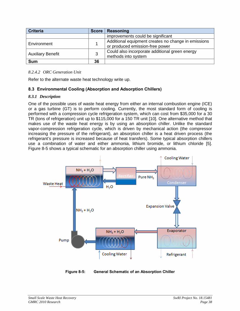
Small Scale Waste Heat Recovery SwRI Project No. 18.15481 GMRC 2010 Research Page 38
Criteria Score Reasoning improvements could be significant
Environment 1 Additional equipment creates no change in emissions or produced emission-free power
Auxiliary Benefit 3 Could also incorporate additional green energy methods into system
Sum 36 8.2.4.2 ORC Generation Unit
Refer to the alternate waste heat technology write up.
8.3 Environmental Cooling (Absorption and Adsorption Chillers) 8.3.1 Description
One of the possible uses of waste heat energy from either an internal combustion engine (ICE) or a gas turbine (GT) is to perform cooling. Currently, the most standard form of cooling is performed with a compression cycle refrigeration system, which can cost from $35,000 for a 30 TR (tons of refrigeration) unit up to $115,000 for a 150 TR unit [10]. One alternative method that makes use of the waste heat energy is by using an absorption chiller. Unlike the standard vapor-compression refrigeration cycle, which is driven by mechanical action (the compressor increasing the pressure of the refrigerant), an absorption chiller is a heat driven process (the refrigerant’s pressure is increased because of heat transfers). Some typical absorption chillers use a combination of water and either ammonia, lithium bromide, or lithium chloride [5]. Figure 8-5 shows a typical schematic for an absorption chiller using ammonia.
Figure 8-5: General Schematic of an Absorption Chiller

Small Scale Waste Heat Recovery SwRI Project No. 18.15481 GMRC 2010 Research Page 39
Here, the waste heat is used to separate the ammonia from the water, and then the ammonia is used to cool a refrigerant. Sometimes, if the desired temperature is not below water’s freezing point, the refrigerant can be water.
An alternative to absorption chillers is a closely related technology, adsorption chillers. These units, instead of relying on mechanical or heat/ cooling cycles to drastically change the pressure of a working fluid, make use of the interaction between solids and gases. Figure 8-6 shows a basic schematic for an adsorption chiller.
Figure 8-6: Schematic for Operation of an Adsorption Chiller
During the refrigeration process, the refrigerant is cooled when the cooling water evaporates taking energy from the refrigerant stream (evaporation is also supported by maintaining a very low pressure in the entire system). The evaporated water then passes into the adsorption chamber, where it is absorbed by the adsorbent (the green area). The heat of the adsorbent is dissipated by circulating additional cooling water through it (when the valve is in position 1), and at this point, no waste heat is being circulated through the line. To recharge the adsorbent (remove the water vapor or desorb it), the cooling water valve switches to position 2, so that the cooling water is supplied to the condenser. The condenser is also fed by the water vapor that is released from the adsorbent when heat is supplied by the waste heat which is circulated for this process. The condensed water is then fed back into the cooling water supply [8].
In this basic setup, the adsorption chiller must alternate between the refrigeration and desorbing processes, so it is not a consistent cooling system. However, alternate designs can make use of multiple adsorption chambers to create a more consistent refrigerant supply.

Small Scale Waste Heat Recovery SwRI Project No. 18.15481 GMRC 2010 Research Page 40
8.3.2 Equipment Requirements
8.3.2.1 Absorption Chiller
Absorption chiller units are available for purchase from multiple vendors. Ideally, however, they will be designed to fit the application in which they will be used. Therefore, if the desire is to provide environmental cooling, the size of the environment and the expected cooling load will need to be determined, along with the amount of heat that will be required. Also, the units will typically need to be designed to work with the waste heat energy. There are some off the shelf units that, if modified properly, could make use of waste heat instead of having it supplying by a fuel source. These units typically run in the range of $1,000/TR [9]. A 30 TR absorption unit would cost nearly $30,000, and a 150 TR unit would cost approximately $150,000.
In addition to the absorption unit, some additional equipment that might be required: a heat exchanger to transfer heat energy from the exhaust stream to the chiller unit (although direct heating is a possibility) and equipment necessary to provide and deal with the additional cooling water required by the process (if not included in the unit package).
8.3.2.2 Adsorption Chiller
Similar to absorption chillers, there are vendors for the design and purchase of adsorption units. These units should be designed to fit the specific needs of the station. Unlike absorption chillers, however, it is most likely that heat from the exhaust stream must be transferred to the unit by way of a heat exchanger and thermal fluid system (direct fired is much less of an option). Whether the cooling water is integrated into the chiller unit or supplied from the station is another matter that will have to be determined when selecting and designing the unit. One manufacturer had units with capacities for cooling from 30 TR to 150 TR for approximately $100,000 to $250,000, respectively [11].
8.3.2.3 Installation and Maintenance
Regardless of which type of unit is selected, depending on how exactly the unit will be installed, the station may have to be shut down for the installation. Alternatively, it may be sufficient to merely shut down the unit that will supply the waste heat. It has to be considered how the cooling load will be supplemented, should the unit not be running or is running at loads that supply less than the necessary heat to the absorption unit. One possibility is to have a heat that runs off a supplied fuel that can provide the heat energy, if needed. Should the cooling unit fail, unless the cooling being supplied is for a critical environment (such as a variable frequency drive equipment space), the station operation should not be impacted. Additional maintenance scheduling is needed for any additional equipment; and depending on the type of working fluids used, additional permitting may be required.
8.3.3 Scoring
8.3.3.1 Absorption Chillers
Criteria Score Reasoning
Capital Cost 2 A 150TR unit will cost in $100k range, and will use approximately 10MMBTUH
TRL 5 Units currently available for purchase from multiple vendors
Impact on Station 3 Failure of unit is likely just an inconvenience, but if cooling a critical space (like a VFD equipment room), could require shutdown of auxiliary units

Small Scale Waste Heat Recovery SwRI Project No. 18.15481 GMRC 2010 Research Page 41
Criteria Score Reasoning
Payback 2 Cost of unit compared to reduced cooling bill will likely take significant time to recover cost, but possible.
Maintenance 3 Depending on type of working fluids, unit could require at least quarterly maintenance
Reliability 3 Unknown failure rate
Operation / Training 3 Understanding of unit process, and additional hazard awareness will be required by local personnel
Permitting 3 Depending on type of working fluids, unit could require additional permitting be performed
Efficiency Improvement 2 Overall station efficiency will increase because of reduced energy costs for cooling
Environmental Benefit 3 Reduced need for combustion to provide heat to unit Auxiliary Benefit 1 No added benefits of unit Weighted Average 2.74 8.3.3.2 Adsorption Chillers
Criteria Score Reasoning
Capital Cost 2 A 150TR unit will cost in $100k range, and will use approximately 10MMBTUH
TRL 4 Units currently available for purchase, however, only one manufacturer was found
Impact on Station 3 Same impact as absorption chiller
Payback 2 Cost of unit compared to reduced cooling bill will likely take significant time to recover cost, but possible.
Maintenance 4 Working fluid is only water, so less maintenance is required
Reliability 2 Units are not as prevalent in industry, so reliability has not truly been documented
Operation / Training 4 Understanding of unit process will be required by local personnel
Permitting 5 Units pose no additional hazards that could require extra permitting
Efficiency Improvement 2 Overall station efficiency will increase because of reduced energy costs for cooling
Environmental Benefit 3 Reduced need for combustion to provide heat to unit Auxiliary Benefit 1 No added benefits of unit Weighted Average 2.63 8.4 Environmental Heating 8.4.1 Description
One of the most direct uses of waste heat from either an internal combustion engine (ICE) or a gas turbine (GT) is to use the heat energy to perform environmental heating. Instead of using a natural gas or electric furnace, a simple heat exchanger could take heat from the engine exhaust stream for use in a heating system.
According to data available at DOE’s Energy Information Administration website, a small office building (1,001 to 5,000 square feet) will use approximately 137,000 cubic feet of natural gas;

Small Scale Waste Heat Recovery SwRI Project No. 18.15481 GMRC 2010 Research Page 42
67% of which is for space heating. If available exhaust energy could be used as the sole source of energy for a heating system in a small office space, an annual saving of nearly $450 is possible [23].
If we assume that this heating only takes place from November to February, then the amount of energy required equates to approximately 32 MBPH (thousand-BTU/hr). This amount of heat is present in all GT and ICE exhaust streams. The space that requires heating will, of course, play a direct role in determining whether this waste heat recovery method will be viable.
8.4.2 Equipment Requirements
As mentioned, this technique for using waste heat would require a heat exchanger in order to transfer the waste heat energy to the heating system. It is possible to use the exhaust gas directly; however, issues could develop when trying to maintain the thermal energy over long distances and because of the possibility for leaks of the exhaust gas into a closed environment. A system using a thermal fluid can better avoid these issues as well as allow for more control in the final amount of energy transferred.
To implement the system, the unit to supply the heat energy would have to be shut down for initial install. After that, there would be little impact on running of the unit. The only negative is that the heat exchanger could provide some back pressure on the engine, reducing the efficiency. If the energy transfer system did fail or the engine was not running at the time heating is needed, there would need to be some fueled source required to provide heat to the heat system.
8.4.3 Scoring
8.4.3.1 Environmental Heating
Criteria Score Reasoning
Capital Cost 2 The cost of heat exchangers can be relatively cheap depending on size, however, the amount of waste heat used is very low
TRL 5 Heat exchangers are common equipment in the industry
Impact on Station 4 Failure of heat exchangers would be little more than an inconvenience
Payback 2 Low savings will take extensive time to offset cost of equipment
Maintenance 4 Little more than yearly maintenance should be required
Reliability 4 Heat exchangers are common enough in industry
Operation / Training 5 Additional equipment requires no additional consideration from personnel
Permitting 5 No additional permitting likely
Efficiency Improvement 2 Overall station efficiency will increase because of reduced energy costs for heating
Environmental Benefit 5 Emissions from natural gas heaters will be eliminated Auxiliary Benefit 1 No additional benefits Weighted Average 3.53

Small Scale Waste Heat Recovery SwRI Project No. 18.15481 GMRC 2010 Research Page 43
8.5 Flare Improvement 8.5.1 Description
Flaring is the process by which gases that must be rejected to the atmosphere can be reduced to less toxic forms. Although it would be desirable to eliminate the need for flaring entirely, the option to retrieve hydrocarbon vapors from the flare stream or, at the very least, ensure proper operation of the flare is considered one aspect where waste heat could possibly be used.
Often, when natural gas is a byproduct in an area where there is no infrastructure to use it, the gas is flared to the atmosphere [39]. One alternative to flaring would be the storage/ transportation of the gas for use. This would require the development of the necessary infrastructure. In other locations where the natural gas is unintentionally put into the flare gas stream, a recovery unit utilizing waste heat from nearby engines could be used to separate the usable gas from that which will need to be flared so that it can be placed back into a product pipeline/ storage. This will likely require the use of a cooling stream; so an absorption/ adsorption chiller, or similar technology, could be used to incorporate the waste heat (see the appropriate sections for more on this capability).
In the more common instance, waste heat can be utilized to ensure that natural gas or any other components of the flare stream do not condensate in the flare header, which is an undesirable scenario for a number of reasons. Therefore, to ensure proper operation of flaring, waste heat from a nearby engine can be transferred to the flare gas stream to ensure that all components remain in a vapor state. Many flares also make use of steam as a way to mix the flare gas stream with air, thereby optimizing the combustion process. In this case, the waste heat from the engine could be used to pre-heat the water to reduce the amount of energy that is used in making the steam [40, 41].
8.5.2 Equipment Requirements
Where cooling is required, refer to the other sections for equipment requirements. In order to transfer heat, either a direct or an indirect transfer is possible. By running the flare gas stream or the water for steam production straight through the exhaust stream of the engine, there is less chance of thermal losses; however, better control is offered by having a set of heat exchangers: one in the engine exhaust and the second in the flare stream/ water stream.
In both cases, if the flaring operation is critical, a backup heat source will be required in case the engine is not in operation. The steam generator would already be equipped for this; it would simply be a matter of expending more fuel at the boiler. Otherwise, disruption of the heat exchangers should have little to no effect on the operation of the unit.
To install the system, the engine unit would have to be shut down, and the entire station would likely have to be shut down in order for work to be done on the flare header.
8.5.3 Scoring
8.5.3.1 Flare Gas Stream Heating
Criteria Score Reasoning
Capital Cost 3 Set of heat exchangers to support using as much waste heat as possible in a GT
TRL 5 Heat exchangers are readily available from multiple manufacturers

Small Scale Waste Heat Recovery SwRI Project No. 18.15481 GMRC 2010 Research Page 44
Criteria Score Reasoning
Impact on Station 4 Failure of heat exchangers do not necessarily mandate a shutdown of any unit
Payback 1 There is no cost saving or monetary benefit to offset cost of additional equipment
Maintenance 4 Low-impact of units likely means lower amount of maintenance
Reliability 4 Heat exchangers are widely developed equipment, so they are seen as rather reliable
Operation / Training 5 There is no additional training or operational considerations required for use of heat exchangers
Permitting 4 A slight change in permitting may be required because of alteration of flare conditions
Efficiency Improvement 1 Alteration to flaring has little to no effect on overall station efficiency
Environmental Benefit 1 No change to emissions Auxiliary Benefit 1 There are no auxiliary benefits Weighted Average 2.88 8.5.3.2 Steam Pre-Heating
Criteria Score Reasoning
Capital Cost 3 Set of heat exchangers plus additional equipment for steam production/usage likely in $100k range to support using as much waste heat as possible
TRL 5 Heat exchangers and steam flares are readily available from multiple manufacturers
Impact on Station 3 Failure of steam production could necessitate shutdown of station if flaring is critical
Payback 1 There is no cost saving or monetary benefit to offset cost of additional equipment
Maintenance 3 Increased equipment for steam production will likely increase amount of scheduled maintenance
Reliability 4 Heat exchangers and boilers are commonly used equipment, so they are seen as rather reliable
Operation / Training 1 Presence of steam at station dictates a 24/7 presence Permitting 1 Because of steam,
Efficiency Improvement 1 Alteration to flaring has little to no effect on overall station efficiency
Environmental Benefit 5 Less emissions made during creation of steam Auxiliary Benefit 1 There are no auxiliary benefits Weighted Average 2.97
8.6 Fuel Gas Pre-Heating 8.6.1 Description
Depending on the fuel gas used and the local environmental conditions, it is possible that condensates (water or hydrocarbons) can form prior to injection into a gas turbine. If these condensates are not removed prior to injection into a gas turbine, serious catastrophic damage can occur [1]. To deal with this issue, a filter or separation system can be placed in the fuel

Small Scale Waste Heat Recovery SwRI Project No. 18.15481 GMRC 2010 Research Page 45
supply line, or the fuel gas can be heated to keep the temperature above the gas dew point. The second option could be adapted to utilize waste heat from the turbine exhaust stream.
8.6.2 Equipment Requirements
As with many of the thermal uses for waste heat, a direct heating could be employed where the exhaust stream is directly used to heat the gas or liquid stream of interest. Since the stream of interest in this case is the fuel gas, an extremely dangerous scenario is possible with this method: the fuel gas could be heated too much and ignites. Therefore, this application of waste heat should use a set of heat exchangers with an intermediate thermal fluid for transfer of the thermal energy, resulting in a system similar to what is shown in Figure 8-7.
Figure 8-7: Schematic for Fuel Gas Pre-Heating
This use of waste heat also has some added benefits. For one, this setup is very similar in concept to a regenerator, a well established method for improving overall turbine efficiency. Also, because the fuel gas would be at a higher temperature going into the gas turbine, it will be easier to ignite. This could also be an issue, however, as it could result in pre-ignition. So the amount of heat transfer from the exhaust stream to the fuel gas needs to be regulated to ensure the temperature does not approach within some limit of the auto-ignition temperature (400° F to 550° F [2] for the heavy liquid components of the fuel).
In instances where the unit is not running or the heat exchanging system fails (so that no waste heat is available), a heater will be necessary to provide the required temperature increase of the fuel gas, if this is deemed a necessity.
8.6.3 Cost Analysis
Since the primary benefit of this application of waste heat is to prevent failure of a gas turbine, there is no realized capital benefit from this use. However, there is a return on the investment of the heat exchanger system because of the savings in electricity that would normally be used for the heating and from the possible beneficial increase of the unit efficiency. Assuming a small gas turbine unit of approximately 1,600 HP, the following cost savings were calculated.
The electricity savings to heat a natural gas fuel stream from its dew point to approximately 50° F higher would take about 7.5 kW; so a unit that runs 50% of the year would garner a savings of about $3,000 by using waste heat instead of electricity. If the gas was heated higher,

Small Scale Waste Heat Recovery SwRI Project No. 18.15481 GMRC 2010 Research Page 46
to a level of about 365° F [3], to improve the performance of the gas turbine, a fuel cost savings could be in the range of approximately $8,000 per year. Using electricity for this temperature increase would cost about $19,000, which would not yield a positive return. So by using the waste heat of the gas turbine, a minor cost savings can be obtained, if the fuel gas is heated to a minimum level; but an alternate method for efficiency improvement is made possible that would increase cost savings by reducing fuel cost in addition to electricity (yields a total of about $11,000 total savings annually). Actual efficiency improvements and overall savings will be dependent on the system.
8.6.4 Scoring
Criteria Score Reasoning
Capital Cost 2
The cost of heat exchangers can vary depending on size, but should be relatively cheap compared to larger pieces of equipment; however, actually uses only a small amount of the available waste heat.
TRL 5 Heat exchangers are commonly used and so are readily available from numerous manufacturers.
Impact on Station 4 Failure of heat exchangers would have little to no effect on unit because of backup heating unit.
Payback 2 The possible efficiency improvements of the system combined with electricity cost savings will provide some recovery for cost of system, but not substantial.
Maintenance 4 Heat exchangers would likely require no more than a yearly scheduled maintenance plan.
Reliability 4 Heat exchangers are common enough in industry to have a well established reliability.
Operation / Training 5 No additional consideration required from personnel. Permitting 5 No additional permitting required. Efficiency Improvement 2 Overall station efficiency could receive a minor gain.
Environmental Benefit 5 Could reduce overall emissions by improving combustion process
Auxiliary Benefit 3 Possible benefit of improved efficiency. Weighted Average 3.60 8.7 Pipeline Gas Pre- and Post- Cooling 8.7.1 Description
A number of different pipeline operations can be affected by the thermal properties of the product fluid or can affect the thermal properties of the fluid, especially if that fluid is a gas. For example, compressors will end up raising the pressure and temperature, and throttling/ control valves will decrease the pressure and temperature. Either change can result in the development of problematic scenarios, such as gas being too hot for the pipeline, which could cause problems downstream. Therefore, in order to maintain certain gas properties, it becomes necessary to cool the gas stream, which can be an extra cost added to operation.
One possibility to reduce this cost is to use the waste heat of a nearby engine in order to perform this cooling. The possibilities for cooling include using the waste heat to power an absorption or an adsorption chiller (discussed in Section 8.3), which can supply a chilled medium to cool a gas after being compressed.

Small Scale Waste Heat Recovery SwRI Project No. 18.15481 GMRC 2010 Research Page 47
An example of the thermal properties affecting the pipeline operation is found in compression, where major benefits can be realized from pre-gas cooling. If the gas is cooled before entering the compressor, this will decrease the required power for compression, because as the gas cools, it becomes denser and less power is required to compress a denser gas. This can lead to energy savings for compression, which can be realized with reduced fuel consumption for an IC engine or gas turbine drive compressor or less electricity for an electric motor drive compressor, or more gas can be passed through the system with the same amount of power input.
8.7.2 Equipment Requirements
For cooling, either an absorption or adsorption chiller will be needed. In addition, a couple of heat exchangers may also be necessary. Having one heat exchanger in the exhaust stream and one in the product stream, with a common thermal fluid linking the two, would allow for more control of how much thermal energy is transferred. However, this would also introduce more thermal inefficiency into the system than if just one heat exchanger was placed in the exhaust stream, and the product stream flowed through it. The specific setup will be dependent on the requirements of the system.
Interruptions to the station would be significant, since this would require modification to the product pipeline for installation of this WHR method. After installation, depending on how critical the cooling is to the operation of the pipeline, any failures of the additional equipment could also cause disruption in service. If the local engine is not in operation, a backup heating source would be required to provide the energy necessary for the cooling of the product stream.
8.7.3 Costs
As far as benefits from the cooling, the pre-cooling can be more easily quantified. Assuming an initial inlet temperature of 100° F, for a compressor working to compress natural gas from 800 psi to 1,100 psi at a standard flow of 400 mmscfd, a decrease in inlet temperature of 10° F could result in either using 171 hp less for mechanical power input to the compressor if the same flow rate is maintained, or the power input could be held constant and the flow increased by about 10 mmscfd [12].
Assuming the cost of gas at $4.76/mscf, if power is reduced to maintain the constant flow, fuel cost savings will be approximately $10k per year (assuming 50% full-load uptime). Or, if the power level is maintained, and the increased flow is selected, revenue could be increased by about $9 million per year (again assuming 50% full-load uptime).
The amount of cooling necessary to create this 10° F drop in temperature is approximately 325 TR. Assuming an efficiency for the absorption chiller of 30% means that the waste heat necessary to drive this temperature decrease would need to be 13 MMBTUH. The waste heat present in a turbine capable of driving this compressor will produce in excess of 25 MMBTUH of waste heat, so this temperature drop is possible.
The largest costs for implementation of this concept would be for the absorption/ adsorption chiller units, which will be approximately $1,000/TR [9], [11]. There is also the additional cost for the heat exchangers, any associated piping/ equipment costs, and the backup heat source.

Small Scale Waste Heat Recovery SwRI Project No. 18.15481 GMRC 2010 Research Page 48
8.7.4 Scoring
Pre-cooling (assumes use of absorption chiller)
Criteria Score Reasoning Capital Cost 2 Cost of chiller (absorption) and additional equipment.
TRL 4 Chiller systems are commercially available; however, these have not been used for this application before
Impact on Station 4
Failure of chiller does not necessarily effect station operation, but there will be an increase in the required compression power or a decrease in product throughput
Payback 5 There could be cost savings from reduction of compression power required or substantial increased revenue from additional product throughput
Maintenance 3 Depending on type of working fluid, unit could require at least quarterly maintenance
Reliability 3 Unknown failure rate
Operation / Training 3 Understanding of unit process, and additional hazard awareness will be required by local personnel
Permitting 3 Depending on type of working fluid, unit could require additional permitting
Efficiency Improvement 2 Overall station efficiency expected to increase due to reduction of compression power required, or increased production
Environmental Benefit 5 Reduced power to compressor will result in lower emissions, or more production for same amount of emissions
Auxiliary Benefit 3 May also require less post cooling of gas since expect gas temperature at exit of compressor to be lower
Weighted Average 3.49
Post-Cooling
Criteria Score Reasoning
Capital Cost 2 Cost of chiller (absorption) that uses low amount of waste heat
TRL 4 Chiller systems are commercially available; however, these have not been used for this application before
Impact on Station 4 Failure of chiller does not necessarily effect station operation, but there will be an increase in the required compression power
Payback 2 Could have minimal cost savings if post gas cooling would be required at station
Maintenance 3 Depending on type of working fluid, unit could require at least quarterly maintenance
Reliability 3 Unknown failure rate
Operation / Training 3 Understanding of unit process, and additional hazard awareness will be required by local personnel
Permitting 3 Depending on type of working fluid, unit could require

Small Scale Waste Heat Recovery SwRI Project No. 18.15481 GMRC 2010 Research Page 49
Criteria Score Reasoning additional permitting
Efficiency Improvement 2 Overall station efficiency expected to increase due to reduction of power for post gas cooling fin fan coolers
Environmental Benefit 1 No change to emissions Auxiliary Benefit 1 No added benefits expected Weighted Average 2.51 8.8 Gas Drying 8.8.1 Description
In almost every situation, natural gas that is extracted from a well site will be saturated with water vapor. To improve performance and protect equipment downstream of the well, it is common practice to remove this water vapor or dry the gas as much as possible [42].
There are two methods that are most prevalent in the industry: glycol drying and solid desiccant drying. Both methods rely on a desiccant medium that is hygroscopic, which is the property of attracting water molecules, to remove the water vapor from the natural gas. The only real difference is that the glycol is a liquid, and the desiccant is a solid. General schematics of the two processes for these two methods are shown in Figure 8-8 and Figure 8-9. In these two schematics, however, the option for using waste heat is illustrated.
Figure 8-8: Glycol Gas Drying Simplified Process Schematic
The process for the glycol gas drying (typically using triethylene glycol) is relatively straight forward; the dry, or lean, glycol is sprayed into a drying tower (or sometimes it is pumped into a stack of trays within the drying tower) so that as the wet gas passes through the drying tower, the water vapor is drawn out of vapor form and absorbed by the glycol. The then wet, or rich, glycol is removed from the drying tower and passed to a regenerator, which is in essence a boiler. The water, which boils at 100° C, is boiled out of the solution while the glycol, which boils

Small Scale Waste Heat Recovery SwRI Project No. 18.15481 GMRC 2010 Research Page 50
at about 330° C [43], remains behind. The now lean glycol can then be pumped back into the drying tower to restart the cycle. This is just a simplified explanation, as most systems today have various other designs to improve efficiency and reduce leaked emissions.
Figure 8-9: Desiccant Gas Drying Simplified Process Schematic
The process for the solid desiccant (normally silica gel) drying is similar, but somewhat more complex. Because the desiccant is solid, there is no pumping involved. Instead, the desiccant is contained in a vessel that the natural gas must pass through. As the gas passes through the vessel, the water vapor is drawn out of the gas and absorbed by the desiccant. At some point, the solid desiccant will become saturated and stop removing water vapor; at this time, the desiccant must either be recharged or replaced.
For this study, focus will be placed on the recharging option. To recharge the desiccant, heat is circulated through the desiccant to force the water vapor out, and then this vapor is removed from the vessel. For the typical solid desiccant, silica gel, a temperature above 120° C is required for recharging. While this recharging is being performed, the natural gas is typically passed through an alternate drying chamber. The two chambers are cycled between drying and regenerating in order to keep a constant gas stream.
8.8.2 Equipment Requirements
To refit a drying unit to make use of waste heat, a set of heat exchangers might be necessary depending on the type of system installed, and how much heat is required. The glycol method would require a set of heat exchangers to avoid transferring too much heat from the waste stream to the regenerator, which could cause the glycol to boil off. The solid desiccant method could make use directly of the exhaust stream (silica gel will not melt until above 1,500° C); however, since the solid desiccant cannot be piped to the exhaust stream, the exhaust stream would have to be piped to the dryer. It might be more practical to have a set of heat exchangers to transport the thermal energy between the two locations.

Small Scale Waste Heat Recovery SwRI Project No. 18.15481 GMRC 2010 Research Page 51
In addition, since the drying of the gas is so beneficial, a backup heating source should be provided in case either the heat exchangers fail, or the unit providing the waste heat is not in operation.
8.8.3 Cost Analysis
To regenerate the desiccant medium, either liquid or solid, the fuel cost of the regenerator can be reduced by using the engine waste heat. The actual savings will be dependent on the size of the system and the type of desiccant used. Some systems, which can handle just over 40 MMSCFD, would require as much energy as 2.3 MMBTUH, if the desiccant is silica gel [44]. This level of energy is available in most engine exhaust streams and could save nearly $100k per year (assuming 50% up-time), if the heat was being supplied by natural gas, or much more if the heat was supplied by an electric heater (depending on cost of electricity).
A glycol system would have to be designed to a specific system’s needs, so cost savings are not as readily available; however, a unit for regular air dehumidification that is capable of handling 35 MMSCFD requires about 0.5 MMBTUH [45, 46]. Assuming similar heat requirements for a natural gas unit means, there could be a savings of almost $22k per year with natural gas as the fuel [47, 48].
8.8.4 Scoring
8.8.4.1 Glycol Drying
Criteria Score Reasoning
Capital Cost 3 Cost of heat exchangers relatively low, but also using lower amounts of waste heat
TRL 5 Heat exchangers and drying units capable of multiple heat sources are common.
Impact on Station 5 Little to no impact on station operation assuming backup heat source.
Payback 3 The cost savings will make for a quick payback. Maintenance 4 Additional yearly maintenance for the heat exchangers. Reliability 4 Heat exchangers are common to industry. Operation / Training 5 No additional operational considerations. Permitting 5 No additional permitting likely.
Efficiency Improvement 3 Efficiency improvement can be large if dealing with high volume of gas drying, and a low-efficiency engine.
Environmental Benefit 5 Removal of natural gas heating will reduce emissions Auxiliary Benefit 1 No other added benefits Weighted Average 4.01 8.8.4.2 Solid Desiccant Drying
Criteria Score Reasoning
Capital Cost 3 Cost of heat exchangers relatively low, but also using lower amounts of waste heat
TRL 5 Heat exchangers and drying units capable of multiple heat sources are common.
Impact on Station 5 Little to no impact on station operation assuming backup heat source.
Small Scale Waste Heat Recovery SwRI Project No. 18.15481 GMRC 2010 Research Page 52
Criteria Score Reasoning
Payback 4 The large cost savings will make for a very short payback.
Maintenance 4 Additional yearly maintenance for the heat exchanger. Reliability 4 Heat exchangers are common to industry. Operation / Training 5 No additional operational considerations. Permitting 5 No additional permitting likely.
Efficiency Improvement 3 Efficiency improvement can be large if dealing with high volume of gas drying, and a low-efficiency engine.
Environmental Benefit 5 Removal of natural gas heating will reduce emissions Auxiliary Benefit 1 No other added benefits Weighted Average 4.13 8.9 Gas Treatment from Waste Heat 8.9.1 Description of Idea
8.9.1.1 Sour Gas Treatment
Sour gas treatment is used to remove corrosive hydrogen sulfide (H2S) from natural gas and other hydrocarbons. The typical method of treatment is to remove the hydrogen sulfide from the gas using an absorber and, in a different process, converting the captured hydrogen sulfide (gas) into sulfur and other byproducts. Both processes involve heating gases or liquids, so there is a potential to increase efficiency using waste heat. Sour gas typically refers to natural gas with both hydrogen sulfide and ammonia, while acid gas refers to natural gas with only hydrogen sulfide [49]. For the current discussion, both sour and acid gas will be referred to as “sour gas” as they both can be treated with these processes.
The first process in the sour gas treatment is the use of an amine extraction process to remove the hydrogen sulfide from the natural gas [49]. The amine solution (absorbent) used can be one of any number of amine solutions, but in this discussion, the amine solution methyldiethanolamine (MDEA) is used. The sour gas enters the amine absorber (also referred to as a contactor) in which the natural gas flows up through the bottom, and the amine liquid flows down from the top [50]. The contactor is often a tall cylindrical structure (see Figure 8-10). The contactor is constructed with multiple shelves on which the amine solution pools, starting at the top and then dropping to successively lower shelves [50]. The natural gas is forced to bubble up through each pool, while the solution strips the hydrogen sulfide from the gas [50]. Once the gas reaches the top of the contactor, the gas is free from hydrogen sulfide and considered “sweet”. By the time the amine solution reaches the bottom of the contactor, it is saturated (rich) with hydrogen sulfide.
The saturated amine solution is then regenerated to remove the hydrogen sulfur and reused in the contactor. The regeneration includes a flash separator, filters, a still (also called a stripper), and a reboiler tank [50]. The reboiler tank is the element that could be modified to take advantage of waste heat. A reboiler heats both the amine solution and vapor (mostly steam) [50]. The vapor is sent up through the sill while, at the same time, amine solution is dropped from the top of the tank. The setup is similar to the contactor with the rich absorbent flowing over plates and the vapor bubbling through the absorbent [50]. At the bottom of the still, part of the hydrogen sulfide has been removed from the amine solution. The amine solution is then returned to the reboiler, where it is heated to 240 to 300° F, and the remainder of the hydrogen sulfide is removed [50]. The hydrogen sulfide is piped away from both the still and reboiler to be

Small Scale Waste Heat Recovery SwRI Project No. 18.15481 GMRC 2010 Research Page 53
disposed or for additional processing. In the products briefly reviewed, it appeared that the heat provided to the reboiler was generated on the regenerator skid and transferred to the amine solution via oil or other medium. If waste heat is used to heat the reboiler instead, there would be a potential for an increase in the efficiency of the entire process.
Figure 8-10. The Amine Extraction Process [51]
The second process in the treatment of sour gas is to convert the hydrogen sulfide gas into sulfur. The process most often used is based on the Claus method. In this method, the hydrogen sulfide is burned or heated in a combustor [49]. Natural gas that has been removed with the hydrogen sulfide is used as the fuel, or auxiliary fuel is added [50]. The combustor is used to partially oxidize the hydrogen sulfide and typically occurs at 1,800 to 2,600° F [52]. Additional catalytic steps are then taken to further remove sulfur. These catalytic steps require cooling and heating between steps. The hydrogen sulfide is typically heated up to 650° F [52]. This heating process can use hot-gas bypass, indirect steam, heat exchangers, or direct-fired heaters [49]. While waste heat could be used for these heating cycles, it makes more sense to use the waste heat from the Claus combustor (hot-gas bypass) which is already commercially available. Therefore, this process will not be considered as a candidate for waste heat from compressors. A Claus process that uses waste heat from the combustor is shown in Figure 8-11.

Small Scale Waste Heat Recovery SwRI Project No. 18.15481 GMRC 2010 Research Page 54
Figure 8-11. Claus Process to Generate Sulfur from Hydrogen Sulfide [49]
8.9.1.2 Wet Gas Treatment
In this discussion, wet gas refers to gas which includes unacceptable levels of water vapor. Only water vapor is considered, because the glycol process that is typically used to remove excess water is quite similar to the amine extraction process used to remove hydrogen sulfide. The glycol absorption method uses an absorber tower/ contactor, regeneration unit (still), and a reboiler in the same way as the amine extraction method. Tri-Ethylene Glycol (TEG) is typically used in this process. Again, the reboiler is the element that can be fitted to use waste heat. A typical reboiler uses a burner to heat the glycol (instead of oil heat exchanger as in the amine process) which could be replaced with waste heat [50]. The temperature used in the reboiler must be controlled to a temperature less than 400° F to prevent adverse affects on the glycol. Such a control will likely complicate the implementation of exhaust heat.
8.9.2 Equipment Requirements
The main equipment requirements will be to provide a means to pump the waste heat to the reboiler (for either the amine or glycol process). If the exhaust from a turbine or other driver can be used directly, the exhaust could be routed directly to the boilers. Otherwise, an intermediate heat exchanger will be required between the exhaust and the reboiler. In addition, means to control the temperature in the reboiler are also required. For a direct exhaust solution, atmospheric air could be combined with the exhaust to lower the temperature of the exhaust passed into the reboiler, or the flow rate could be adjusted. A direct use of exhaust would also likely require a different heat exchanger within the reboiler with more surface area. Such a change to the reboiler would likely require a redesign by the manufacturer. Adding an intermediate heat exchanger; however, would make it possible to use existing reboiler equipment. An intermediate heat exchanger would require a higher temperature exhaust than the direct method and may also require additional pumps.

Small Scale Waste Heat Recovery SwRI Project No. 18.15481 GMRC 2010 Research Page 55
8.9.3 Cost Considerations
The following calculations were performed to give an estimate of the magnitude of the efficiency benefits that heating reboilers with exhaust heat could provide.
Table 8-3 below provides some example values for a system with sour gas. For a system designed to process 77 mmscfd of sour gas, a rate of 333 gph of absorbent flow is required [50]. The amount of hydrogen sulfide in the example was not provided, but the following data and calculation should still provide the estimated magnitude of possible savings. Properties of MDEA at 50% concentration were used.
Table 8-3. Sour Gas Data
Symbol Property Value Units Q Total flow of sour gas 77 [50] mmscfd Q Required absorbent flow 333 gph c MDEA specific heat 0.92 [53] Btu/(lbm*°F) ρ MDEA density 8.38 [53] lbm/gal ∆T Temperature difference 120 to 264 °F
Total power savings = Q*ρ*c*ΔT = 140 hp (1.9 hp per 1mmscfd of sour gas)
The power savings of 140 hp appear to be large enough to merit further investigation. Losses in both the current system and the proposed waste heat system were not calculated or included in the above calculation. Such considerations would be necessary in any detailed analysis.
The properties in Table 8-4 below were chosen to be similar to the amine calculation. The glycol flow was calculated based on a single stage unit with 10 pounds water per mmscf after processing. To remove more water from the gas, greater flow is likely to be required. A flow rate of 8 gal of TEG per pound of water was required to reduce the water level to 10 pounds [54].
Table 8-4. Wet Gas Data
Symbol Property Value Units Q Total flow of sour gas 77 mmscfd Q Required glycol flow 1258 gph c MDEA specific heat 0.525 [55] Btu/(lbm*°F) ρ MDEA density 9.39 [55] lbm/gal ∆T Temperature difference 120 to 380 °F
Total power savings = Q*ρ*c*ΔT = 634 hp (8.2 hp per 1mmscfd of sour gas) The power savings of 634 hp is large enough to merit further investigation. Losses in both the current system and the proposed waste heat system were not calculated or included in the above calculation. Such considerations would be necessary in any detailed analysis.
8.9.4 Impact on Station
The main impact of rerouting exhaust to power a reboiler is piping, potential addition of an intermediate heat exchanger, and potentially, a new boiler design. The sour gas treatment reboiler would likely require a new design that would not be compatible with current oil heating technology. It is possible that the glycol reboiler could be design to operate with both exhaust heat and fired burners (as a backup). If no backup system is provided, the process will be

Small Scale Waste Heat Recovery SwRI Project No. 18.15481 GMRC 2010 Research Page 56
dependent on turbine or engine exhaust to operate. If the driver was to be shut down and the absorber process still required, then the absorber system would also have to be shut down disabling gas production. However, it is expected that for most cases, if the driver is shut down, then gas movement will also be stopped.
8.9.5 Scoring
Criteria Score Reasoning
Capital Cost 3 Most of the equipment required will be to direct exhaust gas. New reboiler or intermediate heat exchanger may be necessary.
TRL 2 Application of waste heat to reboilers doesn’t appear to have been done before.
Impact on Station 3 Exhaust heat will be required for the gas treatments to operate, but it is expected that while drivers are shut down gas processing will not be necessary.
Payback 2 The payback will be in the form of improved efficiency. Savings could be as much horsepower required by a small driver.
Maintenance 4 Restricted mostly to pumps. Reliability 4 Possible addition of fans or pumps. Operation/Training 5 No special or extensive training is expected. Permitting 4 Not expected to be difficult to permit. Efficiency improvement 4 Efficiency improvements equivalent of a small driver.
Environmental Benefit 5 Using waste heat instead of combustion will reduce emissions
Auxiliary benefits 1 No auxiliary benefits expected. Weighted Average 3.44 8.10 Thermal Energy Storage to Provide Power for Gas Turbine Restart 8.10.1 Description of Idea
Thermal Energy Storage (TES) is a technique that may be used to store energy in the form of heat. Heat can be stored in a liquid, gas, or solid medium. There are three methods for thermal energy storage systems: sensible heat storage, latent heat storage, and bond energy storage [30]. Sensible heat storage is energy stored in a solid or liquid by means of a temperature change without changing phase. Latent heat storage is energy stored in a liquid or solid by means of a phase change in the material. Bond energy storage is energy stored in a liquid, solid, or gas by means of shifting equilibrium points for a chemical reaction.
When designing a TES system, some considerations must be made with regard to operating temperature range, energy storage capacity, duration of storage, cost, and rate of charge/ discharge [30]. Each of the three methods for storage outlined above has advantages and disadvantages. For example, latent heat (phase change) energy storage can be beneficial over sensible heat energy storage, since the latent heat of fusion is generally a much higher value than an enthalpy change from 1 Kelvin [30]. Latent heat storage can also be beneficial due to its smaller size relative to the other methods. However, if cost considerations are important, then the sensible heat energy storage system would be a prime candidate.
One factor that must be considered for each of the three methods is heat loss. Some TES systems use insulation eight or more inches thick [30]. Insulation can be a significant cost,
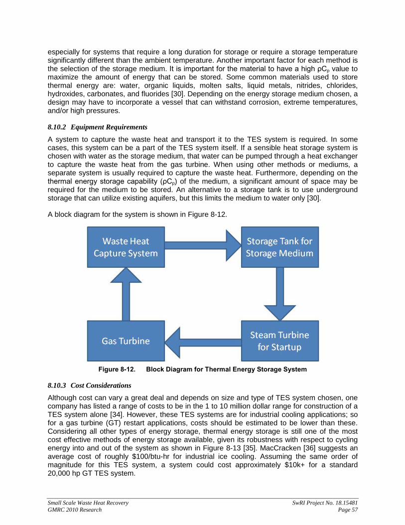
Small Scale Waste Heat Recovery SwRI Project No. 18.15481 GMRC 2010 Research Page 57
especially for systems that require a long duration for storage or require a storage temperature significantly different than the ambient temperature. Another important factor for each method is the selection of the storage medium. It is important for the material to have a high ρCp value to maximize the amount of energy that can be stored. Some common materials used to store thermal energy are: water, organic liquids, molten salts, liquid metals, nitrides, chlorides, hydroxides, carbonates, and fluorides [30]. Depending on the energy storage medium chosen, a design may have to incorporate a vessel that can withstand corrosion, extreme temperatures, and/or high pressures.
8.10.2 Equipment Requirements
A system to capture the waste heat and transport it to the TES system is required. In some cases, this system can be a part of the TES system itself. If a sensible heat storage system is chosen with water as the storage medium, that water can be pumped through a heat exchanger to capture the waste heat from the gas turbine. When using other methods or mediums, a separate system is usually required to capture the waste heat. Furthermore, depending on the thermal energy storage capability (ρCp) of the medium, a significant amount of space may be required for the medium to be stored. An alternative to a storage tank is to use underground storage that can utilize existing aquifers, but this limits the medium to water only [30].
A block diagram for the system is shown in Figure 8-12.
Figure 8-12. Block Diagram for Thermal Energy Storage System
8.10.3 Cost Considerations
Although cost can vary a great deal and depends on size and type of TES system chosen, one company has listed a range of costs to be in the 1 to 10 million dollar range for construction of a TES system alone [34]. However, these TES systems are for industrial cooling applications; so for a gas turbine (GT) restart applications, costs should be estimated to be lower than these. Considering all other types of energy storage, thermal energy storage is still one of the most cost effective methods of energy storage available, given its robustness with respect to cycling energy into and out of the system as shown in Figure 8-13 [35]. MacCracken [36] suggests an average cost of roughly $100/btu-hr for industrial ice cooling. Assuming the same order of magnitude for this TES system, a system could cost approximately $10k+ for a standard 20,000 hp GT TES system.

Small Scale Waste Heat Recovery SwRI Project No. 18.15481 GMRC 2010 Research Page 58
Figure 8-13. Capital Costs of Various Energy Storage Methods with Efficiency and Durability in
Mind [35]
8.10.4 Impact on Station
Depending on the duration of storage and discharge requirements, a significant amount of space may be required for a TES system. Latent heat energy storage requires the least amount of space among the three methods; however, it is also the most costly. For the entire system, a footprint of several hundred to several thousand square feet could be required, but this data is again based on industrial cooling applications [34], which are likely larger systems than those which would be required for GT restart.
8.10.5 Scoring
Criteria Score Reasoning Capital cost 4 Unit to work with a 20,000hp GT costs near $10k TRL 4 Used often with HVAC systems but very little work with GTs Impact on station 4 Should have backup electric motors for restart Payback 2 The increase in efficiency is expected to be very small Maintenance 3 Expected pump and insulation inspection Reliability 3 Little to no experience with technology Operation/ Training 5 No special or extensive training is expected. Permitting 4 Not expected to be difficult to permit. Efficiency improvement 1 Very small; only gains seen are during GT restart Environmental 5 Will reduce emissions from a natural gas fired starter. Auxiliary benefits 1 No auxiliary benefits expected. Weighted Average 3.5

Small Scale Waste Heat Recovery SwRI Project No. 18.15481 GMRC 2010 Research Page 59
8.11 Using Waste Heat to Power Industrial Processes 8.11.1 Description of Idea
In general, industrial processes require a significant amount of energy due to their scale or quantity of product being manufactured. If these types of facilities were located near a pumping station, waste heat could potentially be sold to the industrial facility. A few industrial operations for consideration are:
• Agricultural crop drying • Gypsum board manufacturing facilities • Greenhouses • Foundries • LNG Gasification
Agricultural crop drying is often performed using a resistance heat-fan system. These systems are now being replaced by heat pumps that result in more cost effective drying. The waste heat from a gas turbine (GT) could be tied into the heat pump cycle as a means of powering that cycle. The power required to operate the heat pump would be approximately 20 kW or more [56]. This type of system would be most beneficial in colder climates.
Gypsum board manufacturing facilities often require substantial amounts of energy for their industrial processes, primarily calcination. Because the processes are quite similar, waste heat could also be used in cement plants for the calcination process [57]. This reaction occurs at very high temperatures, so another thermodynamic cycle would likely need to be installed at the manufacturing facility, in order convert the energy to a usable domain.
Greenhouses are a prime candidate for one purpose: heating of the facility throughout the year. Some sources indicate that the cost for greenhouse heating may contribute to 70-80% of the total energy budget [59]. Others suggest that heating and cooling of the greenhouse may contribute to 70-85% of the total operating cost [59]. One method that may be used to convert the waste heat to useful energy for the greenhouse, is to supply a constant 90-100° F-supply of water, and route the water through a radiant heat grid located in the greenhouse floor [59]. However, this method may have a high capital cost and would still require a back-up heating source.
Foundries offer another industrial application for waste heat recovery to be utilized. Foundries require a large amount of energy for melting large quantities of metals. For certain metals with low melting points, propane or natural gas furnaces are used [60]. In this case, waste heat could be used to preheat the gas-fuel flow. However, metals with higher melting points require specialized furnaces that do not use hydrocarbon fuels [60]. Other processes that occur in foundries generally do not require thermodynamic cycles to perform. An option for these would be for the waste heat to supply power to an alternator, which could then feed electric power to the remaining equipment in the foundry.
LNG Gasification plants could utilize a significant amount of waste heat. The plant would only need a heat exchanger to transfer the heat to the LNG. Transporting the energy may be difficult unless it is converted to another form (other than heat) prior to transport. This process is interesting because the gasified LNG could also be used to fuel the GT at the pumping station, meaning that both plants would directly benefit from waste heat usage.

Small Scale Waste Heat Recovery SwRI Project No. 18.15481 GMRC 2010 Research Page 60
8.11.2 Equipment Requirements
In all cases, a heat exchanger and a transport medium would likely be required on the pumping station side. Additional equipment would be required at the manufacturing facility, depending on the application and use. Equipment can range from heat pumps or other thermodynamic cycles to hot water heating grids.
8.11.3 Cost Considerations
If an industrial manufacturing plant could justify the cost for installing equipment at their facility, payback could be achieved in a reasonable time-frame by recovering capital funds through the sale of energy to that facility. Additionally, if the manufacturer saw enough benefit from this method, the manufacturer may be willing to share, or even fully cover, the capital costs required for installing additional equipment in the pumping station. Other considerations may include potential penalties for inadequate/ unsteady power delivery to the facility purchasing the power.
8.11.4 Impact on Station
This method would have virtually no impact on the station. Initial downtime for installation of equipment may be required. After installation, no further disruptions should occur.
8.11.5 Scoring
Criteria Score Reasoning
Capital Cost 3 Equipment may be in the $100k+ range when considering equipment for both the station and manufacturing plant
TRL 4 Some facilities may already use WHR, while others do not
Impact on Station 5 None, other than installation of equipment for transporting the energy
Payback 2 The price for energy sold may be small relative to capital Maintenance 4 Will depend on application.
Reliability 4 Most of the applications will involve fairly simple systems Operation/Training 5 No special or extensive training is expected. Permitting 4 Not expected to be difficult to permit. Efficiency improvement 1 Very small; gains will only be realized through the selling of
Environmental Considerations 1 No emissions reduction at the station
Auxiliary benefits 1 No auxiliary benefits expected. Weighted Average 3.07 8.12 Additional Inlet Air Treating 8.12.1 Description
Besides using waste heat to cool the inlet air for a gas turbine (which is an alternate waste heat method), there are other inlet air treatments that could make use of the engine waste heat. In situations where the ambient air has high humidity, it might be desirable to dry the air [61]; so a drying unit could be employed to remove some of the water vapor from the air before entering the turbine or passing through the filter system. Units for drying air are commercially available. A general description of the more common unit types can be found in the concept description for

Small Scale Waste Heat Recovery SwRI Project No. 18.15481 GMRC 2010 Research Page 61
“Gas Drying.” The waste heat could be utilized, because most of these units require a heat source to regenerate a drying agent (normally either silica gel or glycol).
The major benefit of having dryer air is an increase of inlet air density, which is easier to compress and would contain more oxygen for the combustion process. Also, dryer air could possibly reduce the chance of filter failure or turbine damage from condensing water. However, the process will typically increase inlet air temperature, which has a negative effect on turbine performance.
In a similar method, some applications of inlet foggers have actually demonstrated a capacity for scrubbing the inlet air [62]. That is, by injecting a fog of water above what will evaporate, some dust particles are absorbed by the liquid droplets. Then these droplets can be separated out of the air stream by a vane separator. This pre-scrubbing before passing through the filters could increase the life time of the filters. Drying of the air can be done prior to passing through the filters and into the gas turbine, to ensure no water vapor condenses on its way to the turbine inlet. Unfortunately though, any cooling that occurs because of the fogging would likely be reversed by the gas drying process.
A system combining fogging, dehumidifying, and chilling (by an absorption chiller for example) could possibly be used to achieve the advantages of inlet scrubbing and cooling; and two of the three systems could make use of waste heat. However, all the additional equipment could require more waste heat than what is available, as well as significantly increase the capital cost for implementation.
8.12.2 Equipment Requirements
If a dehumidification system is not already in place for the inlet air, a system capable of handling the volume rate will be required (which could be anywhere between 10,000 and 100,000 SCFM). In addition to handling the air flow rate, the system would also need to be adaptable to allow the regenerator to accept heat from the waste heat stream. As described in the section about “Gas Drying,” a set of heat exchangers would be the most practical setup for transferring the thermal energy.
To attempt scrubbing the inlet air, a fogging system capable of injecting a high rate of liquid into the air stream will be necessary, as well as a vane system to remove the liquid and a treatment system to clean any dust from the water before re-injection.
Finally, if the inlet air is to be cooled, a chilling unit that can use waste heat would be necessary. To facilitate the combined system of the drying and chilling units with waste heat will likely take a larger heat exchanger and transfer system.
8.12.3 Cost Analysis
Considering a small gas turbine rated at near 1,600 hp, the inlet air flow rate is approximately 12,000 SCFM, and the available waste heat from the unit is approximately 9 MMBTUH. A dehumidifier capable of handling the turbine inlet air flow rate could cost around $135k. Combined with the cost of heat exchangers, a complete installation would still be in the $100k-range.
The inlet air humidity and temperature will determine the actual power used by the dehumidifier, but assuming full power consumption, the unit would require nearly 1.13 MMBTUH (and assuming efficiencies of 60% for the two heat exchangers, that would require 3.13 MMBTUH

Small Scale Waste Heat Recovery SwRI Project No. 18.15481 GMRC 2010 Research Page 62
from the exhaust stream). Assuming this energy could be provided from the waste heat, and the heating is being provided by natural gas, the achievable savings are near $11/hr. This, if assuming the unit is run for 50% of the year, is almost a $49k/year savings. If an electric heater is being used, and electricity is taken to cost 8¢/kWh, then the hourly savings increase to about $26, and the yearly savings would be near $115k.
For one particular application of a dryer unit, the air temperature could increase by as much as 50° F. To offset this increase and lower the temperature even further, an improvement in the unit efficiency would require a cooling unit capable of nearly 100 TR, or 1.1 MMBTUH. This size of unit could cost in the range of $150k and would require the waste heat source to have approximately 3.7 MMBTUH of usable energy.
The total combined system of the dehumidifier and the cooling unit would require just less than 7 MMBTUH in the exhaust stream, which is possible for this turbine. The combined cost would be in excess of $200k, and if the improved efficiency, because of cooler inlet air, provides the only savings, which would be approximately $15k/year, then it would take just over 20 years to recover the cost. An improvement of the lifetime for the filter system and the turbine might also be among the benefits, but no data was found to quantify these benefits [44, 45].
8.12.4 Scoring
8.12.4.1 Reduce Inlet Air Humidity (assuming dehumidifier already in place)
Criteria Score Reasoning
Capital Cost 3 Cost of heat exchangers in $10k range, but uses a low amount of waste heat
TRL 4 Heat exchangers common in industry Impact on Station 4 Little to no impact on station
Payback 4 The large cost savings will make for a short payback period.
Maintenance 4 Additional yearly maintenance for heat exchangers Reliability 4 Heat exchangers are common to industry Operation / Training 5 No additional operational considerations Permitting 5 No additional permitting required
Efficiency Improvement 4 Efficiency improvement dependent on volume of air intake
Environmental Benefit 5 Could have reduced emissions because of improved combustion
Auxiliary Benefit 1 No other added benefits Weighted Average 3.98 8.12.4.2 Reduce Inlet Air Humidity (assuming no dehumidifier already in place)
Criteria Score Reasoning
Capital Cost 2 Cost of heat exchangers plus dehumidifier will be in the $100k range, but still uses a low amount of waste heat
TRL 4 Heat exchangers and dryers common in industry
Impact on Station 4 Depending on humidity level and acceptable amount to pass to turbine, could have issue if system goes down
Payback 1 Possible reduction of unit efficiency could make cost of equipment beyond recovery
Maintenance 3 Monthly maintenance for dehumidifier
Small Scale Waste Heat Recovery SwRI Project No. 18.15481 GMRC 2010 Research Page 63
Criteria Score Reasoning
Reliability 4 Heat exchangers and dryers are common to industry, but use of additional chemicals could reduce reliability
Operation / Training 4 Additional operation control for dehumidifier
Permitting 4 Additional chemical permitting may be necessary for drying agent
Efficiency Improvement 1 Efficiency improvement will be offset by decreased efficiency of unit due to increased inlet temperatures
Environmental Benefit 3 Reduced efficiency could counter effects of improved combustion
Auxiliary Benefit 1 No other added benefits Sum 2.87 8.12.4.3 Inlet Air Scrubbing
Criteria Score Reasoning
Capital Cost 2 Adding fogging system to heat exchangers and dehumidifier will still be in $100k range, but still uses a low amount of waste heat
TRL 4 All components are common in industry
Impact on Station 4 Filtering system should be able to provide sufficient filtering without pre-scrubbing or while drying unit is down
Payback 2 High cost of equipment with the possible reduction of unit efficiency might be recoverable if filter system is aided
Maintenance 3 Monthly maintenance likely for additional equipment
Reliability 4 All components common to industry, but use of additional chemicals and liquid could affect reliability
Operation / Training 4 Additional operation control for foggers and dehumidifier
Permitting 4 Additional chemical permitting may be necessary for drying agent
Efficiency Improvement 1 Efficiency improvement will be offset by decreased efficiency of unit due to increased inlet temperatures
Environmental Benefit 3 Could have reduced emissions because of improved combustion
Auxiliary Benefit 0 No other added benefits Weighted Average 2.98 8.12.4.4 Inlet Air Scrubbing + Air Chiller
Criteria Score Reasoning
Capital Cost 3 Adding chiller unit will still be in $100k range and uses more waste heat energy
TRL 4 All components are common in industry
Impact on Station 4 Filtering system should be able to provide sufficient filtering while unit is down
Payback 3 Better unit efficiency will improve payback period Maintenance 3 Monthly maintenance likely for additional equipment
Reliability 4 All components common to industry, but use of additional chemicals and liquid could affect reliability

Small Scale Waste Heat Recovery SwRI Project No. 18.15481 GMRC 2010 Research Page 64
Criteria Score Reasoning
Operation/ Training 3 Additional operation control for all additional inlet conditioning equipment
Permitting 4 Additional chemical permitting may be necessary for drying agent
Efficiency Improvement 2 Combined usage of waste heat and unit efficiency improvement
Environmental Benefit 5 Could have reduced emissions because of improved combustion
Auxiliary Benefit 1 No other added benefits Sum 3.54 8.13 Natural Gas Reforming Pre-Heat 8.13.1 Description
One of the fast growing fuels today is hydrogen, and one of the largest sources of hydrogen is from steam-methane production. One of the large costs of this method though, is the high temperature of steam that is required: 700-1,000° C at between 3-25 bar [63]. One way to reduce the amount of energy required for this heating process, is to use the waste heat from an engine. However, the waste heat produced by most engines is not hot enough to reach the target temperatures alone, but it can at least get the water part way there. If the engine could use hydrogen as a fuel, then a process similar to the diagram in Figure 8-14 would be possible. Alternatively, the turbine could be run using traditional fuel, and the hydrogen produced could simply be a byproduct.
Figure 8-14. One Option for Using Waste Heat to Aid in Natural Gas Reforming

Small Scale Waste Heat Recovery SwRI Project No. 18.15481 GMRC 2010 Research Page 65
The source for the additional heat can be anything from gas burners to renewable sources like solar collectors, which is appealing, if the reason for this modification is to reduce overall emissions along with improving efficiency. Alternatively, this similar method could be used to pre-heat the water in other high-temperature methods for hydrogen creation.
8.13.2 Equipment Requirements
At this point, because of the size and complexity of natural gas reformers, it is unlikely that this WHR method would be reasonable, unless the engine is located near a pre-existing location with a hydrogen production unit that requires steam or another heat source. In this scenario, to make use of the waste heat would require a heat exchanger to perform the pre-heating of the water before the water makes its way to the main boiler that will produce the superheated steam. This would require the unit to be shut down to install the heat exchanger; however, after that, the additional equipment would have little to no effect on the operation of the station.
Research is currently being undertaken to develop more compact reformer units that could perhaps fit within a standard pipeline station. With such a unit, in addition to the heat exchanger to pre-heat the water, the primary boiler would be required. This system would be dealing with such high temperature/ pressure steam that special training and permitting would likely be necessary.
8.13.3 Scoring
8.13.3.1 NG Reforming near station (with natural gas, gas turbine)
Criteria Score Reasoning
Capital Cost 3 Cost in the range of $100K for adding a heat exchanger to use highest amount of waste heat
TRL 5 Heat exchangers that can be used for this already exist
Impact on Station 5 If heat exchanger failed it would not impact station (it would impact company using heat for NG reforming)
Payback 3 Would expect payback for purchasing heat exchanger within 10 years (proceeds from sale of exhaust heat)
Maintenance 4 Yearly inspection and check on heat exchanger required
Reliability 4 Heat exchanging systems have failure rate on the order of greater than 5 years
Operation / Training 4 Only operation would be inspection and checks on heat exchanger (no special system operation)
Permitting 5 Don’t anticipate needing a permit to install a heat exchanger
Efficiency Improvement 1 No efficiency gain from this system. Back pressure from heat exchanger will actually cause reduced gas turbine efficiency.
Environmental Benefit 1 No change to emissions Auxiliary Benefit 1 No auxiliary benefits to the station. Weighted Average 3.19

Small Scale Waste Heat Recovery SwRI Project No. 18.15481 GMRC 2010 Research Page 66
8.13.3.2 NG Reforming near station (with hydrogen gas turbine)
Criteria Score Reasoning
Capital Cost 3 Cost in the range of $100K for adding a heat exchanger to capture the highest amount of exhaust heat to send to reformer
TRL 5 Heat exchangers that can be used for this already exist
Impact on Station 5 If heat exchanger failed it would not impact station (it would impact company using heat for NG reforming)
Payback 1
Would not expect payback due to expenses from installing a hydrogen turbine (this scenario assumes hydrogen is provided to gas turbine by NG reforming company which takes heat from station, minimal cost for both sides)
Maintenance 4 Yearly inspection and checks on heat exchanger required
Reliability 4 Heat exchanging systems have failure rate on the order of greater than 5 years
Operation / Training 4 Only operation would be inspection and checks on the heat exchanger (no special system operation)
Permitting 5 The need for permit to install a heat exchanger is not anticipated.
Efficiency Improvement 1 No efficiency gains expected with heat exchanger or with hydrogen gas turbine from this system.
Environmental Benefit 1 No change to emissions Auxiliary Benefit 1 No auxiliary benefits in the station Weighted Average 2.97 8.13.3.3 NG Reforming stand-alone unit at station (sell hydrogen as byproduct)
Criteria Score Reasoning
Capital Cost 1 Cost expected to be greater than $10 million for NG reforming system to use maximum waste heat
TRL 2 NG reformers exist, but on much larger scale than would be needed for a pipeline station
Impact on Station 5 Shutting down the NG reformer system would not have an impact on the normal pipeline operation
Payback 2 May have payback for system within 20 years (based on successful sales of hydrogen produced)
Maintenance 2 Monthly maintenance items would be required for this system
Reliability 1 The reliability of smaller NG reforming system is unknown since they have not been used
Operation / Training 1 Would expect 24/7 supervision with this type of system due to the use of steam
Permitting 2 Permitting would be required for installing this type of system
Efficiency Improvement 1 Station would not see efficiency gains for pipeline operation with this system.
Environmental Benefit 1 No change to emissions
Small Scale Waste Heat Recovery SwRI Project No. 18.15481 GMRC 2010 Research Page 67
Criteria Score Reasoning
Auxiliary Benefit 4 Would have hydrogen that could be used for other operation (fuel cells, byproduct that is sold, etc…)
Weighted Average 1.93 8.13.3.4 NG Reforming stand-alone unit at station (with hydrogen gas turbine)
Criteria Score Reasoning
Capital Cost 1 Cost expected to be greater than $10 million for NG reforming system to use maximum waste heat
TRL 2 NG reformers exist, but on much larger scale than would be needed for a pipeline station
Impact on Station 1 Shutting down the NG reformer system would affect pipeline operation since hydrogen would not be available (may lead to station shutdown)
Payback 2 May have payback for system within 20 years (based on successful sales of excess hydrogen produced)
Maintenance 2 Monthly maintenance items would be required for this system
Reliability 1 The reliability of smaller NG reforming system is unknown since they have not been used
Operation/ Training 1 Would expect 24/7 supervision with this type of system due to the use of steam
Permitting 2 Permitting would be required for installing this type of system
Efficiency Improvement 1 Station would not see efficiency gains for pipeline operation with this system.
Environmental Benefit 1 No change to emissions
Auxiliary Benefit 3 Could have excess hydrogen that could be used for other operation (fuel cells, byproduct that is sold, etc.)
Sum 1.29 8.14 Oil and Coolant Pre-Heating 8.14.1 Description
Currently, it is desirable to pre-heat the oil and coolant of an engine in order to reduce the stress of a cold start. This would keep the life of the engine as long as possible and allow the operation of the engine within a shorter time period. The heat can be applied to the oil/ coolant reservoirs and allowed to dissipate naturally through the oil/ coolant lines. Alternatively, a small pump can be incorporated to circulate the oil/ coolant through the lines and the engine, which is also more ideal as it better disperses the heat to all elements of the engine.
Standard systems currently used run off of electricity, and the specific power requirements will depend largely on the scale of the engine and its lubrication/ coolant system. The electricity requirements for some heaters can be in the tens of kilowatts but can also run up to the hundreds of kilowatts range.
Waste heat energy could be used in several ways to reduce the cost of pre-heating. First, the electricity used by the pre-heater could have been produced during previous operation of the engine by using a recovery method to create electricity which can be stored for future use (such as an ORC and a battery system). The second way in which waste heat can be used is to store
Small Scale Waste Heat Recovery SwRI Project No. 18.15481 GMRC 2010 Research Page 68
the energy thermally for later use. Lastly, the waste heat from an engine which is already in operation can be used to preheat a nearby engine’s oil during start-up. The source of the waste heat could be exhaust gases, or it could be taken directly from the oil/ coolant.
This technology is primarily useful to internal combustion engines which experience high stress levels associated with cold startup. By reducing the stress levels of startups, it is possible to extend the life of an engine, as well as reduce the overall amount of maintenance required over that lifetime.
8.14.2 Equipment Requirements
8.14.2.1 Electricity Creation and Storage Option
The electrical option would require a system to convert the waste heat into electricity and store the electricity and a heating system that uses electricity to perform the pre-heating. A system to create and store electricity is another waste heat usage option. Numerous electrical pre-heating systems are commercially available for purchase.
Benefits of the electricity storage option include that if the battery storage does not contain enough energy to operate the pre-heater, electricity can be simply purchased from the local grid. Also, additional electricity production methods can be combined to build up the battery charge (such as solar).
As far as the cost of this system, the pre-heating systems are commonly already packaged with the engine units (if a system does not have an oil pre-heater, then this would need to be added), so the only additional cost would come from the electricity production and storage system (please refer to the alternate section for further details).
8.14.2.2 Thermal Storage Option
The thermal storage option would require a heat exchanger to collect waste heat and transfer it to a thermal storage system. Numerous storage systems currently exist with a broad range in cost and complexity. However, all systems typically rely on two components, a material to store the energy (typically something with a high specific heat, such as water) and an insulated container, for example an insulated tank of water. Other options can make use of better storage containers (such as sub-earth facilities) or different materials (especially certain phase-change materials). Additionally, the method would still require a system to transfer the heat from the storage system into the oil/ coolant and for circulation into the lines and engine. This transfer and forced circulation could likely require additional energy costs.
The likelihood of maintaining the thermal energy with the insulation for long periods of time is also a consideration that must be made. A heater could be used to help maintain the temperature or provide heat, should the thermal energy be lost, which would also be an additional cost.
8.14.2.3 Direct Oil Heating Option
For the direct oil heating option, the oil would be heated by the exhaust gas from a nearby engine which is already in operation. For this, a heat exchanger is needed. The heat exchanger would transfer the heat from the exhaust gas to the oil. A pump is still required to circulate the oil through the engine and heat exchanger.

Small Scale Waste Heat Recovery SwRI Project No. 18.15481 GMRC 2010 Research Page 69
Due to the variability in operation of pipeline stations, a nearby engine may not always be running. Therefore, the electric oil heating system must be able to heat the oil even if the exhaust heat is not available. Therefore, the oil heating system must have the heat exchanger for the interaction with the exhaust plus some other heating element. This would most likely be an electrical heating element.
8.14.3 Scoring
8.14.3.1 Electricity ORC
Criteria Score Reasoning
Capital Cost 1 Requires use of an ORC system which is on the order of $10 million to install, and waste heat used for pre-heating is extremely low
TRL 5 ORC systems are currently available and have been used at pipeline stations, also electric heaters are currently used for oil pre-heating
Impact on Station 4 Failure of ORC system does not necessarily impact station. Alternate electricity source could be used for electric heaters
Payback 1 There is no cost saving or monetary benefit to offset cost of additional equipment (ORC system)
Maintenance 2 Monthly maintenance items would be required for ORC system
Reliability 3 Current ORC systems show reliability of 1 to 5 years
Operation / Training 3 Training required for maintenance and operation of ORC system
Permitting 2 May require long and extensive permitting process to implement and ORC cycle
Efficiency Improvement 1 Pre-heating oil with electric heater that uses electricity from an ORC cycle does not provide substantial efficiency improvements
Environmental Benefit 3 Production of emission-free power
Auxiliary Benefit 5 ORC cycle would procedure more electricity than required for pre-heating elements, so this could be used for several other applications
Weighted Average 2.67 8.14.3.2 Thermal Storage
Criteria Score Reasoning
Capital Cost 2 Cost is expected to be in the range of $100K for thermal storage devices, but would only use minimal amount of waste heat
TRL 4 Currently system available that can store thermal energy, but have not been used in pipeline stations before
Impact on Station 4 Station would have minimal impact if this system failed, back up electric heaters would be available
Payback 2 Do not expect much cost advantage of this system, so payback is greater than 20 years

Small Scale Waste Heat Recovery SwRI Project No. 18.15481 GMRC 2010 Research Page 70
Criteria Score Reasoning
Maintenance 4 This system would most likely require only yearly maintenance items
Reliability 4 Static system will most likely have good reliability
Operation/ Training 3 Some training would be required for operators to maintain system properly
Permitting 4 Do not expect permitting requirements unless special solids or chemicals used for thermal storage
Efficiency Improvement 1 Do not anticipate substantial efficiency improvements to station operation
Environmental Benefit 1 No change in emissions Auxiliary Benefit 1 No auxiliary benefits expected Weighted Average 2.62 8.14.3.3 Direct Oil Heating
Criteria Score Reasoning
Capital Cost 3 Only require a heat exchanger, so minimal upfront cost, but only use low amount of waste heat
TRL 4 Heat exchangers are commercially available, even though this type of system has not been used in stations
Impact on Station 4 Station would have minimal impact if this system failed, back up electric heaters would be available
Payback 3 May see cost benefit in long term (10 years)
Maintenance 4 This system would most likely require only yearly maintenance items
Reliability 4 Static system will most likely have good reliability
Operation/ Training 5 Minimal training required since only adding heat exchanger
Permitting 5 No permitting required for addition of heat exchanger
Efficiency Improvement 1 Do not anticipate substantial efficiency improvements to station operation
Environmental Benefit 1 No change to emissions
Auxiliary Benefit 2 Can be used to ensure additional units are kept in quick start condition where required
Sum 3.08 8.15 Production of Distilled Water from Waste Heat 8.15.1 Description of Idea
Waste heat can be used to produce distilled water from a salt water source and sold as a commodity. Desalination plants and fresh water generators that require external sources of heat for operation are a proven technology, available today for a wide range of scales. One large plant in Saudi Arabia produces over 225 gallons of fresh water per second [64]. On the other extreme, fresh water generators are available that produce 132 gallons of fresh water per day [65]. Desalination units have already been used in waste heat applications with sources such as power plants. One company currently offers a product line intended to be powered by waste heat on offshore oil platforms [66].

Small Scale Waste Heat Recovery SwRI Project No. 18.15481 GMRC 2010 Research Page 71
While desalination units have been constructed in oil and gas applications, no compressor station applications for producing fresh water as a commodity are known to exist. It must be determined at what rate fresh water can be produced, whether efficiency can be increased by the process, and if the cost for such an implementation is feasible. Many processes exist to convert salt water to fresh water. Only three of these processes will be considered here. Processes were selected that require external heat input to operate and are commercially available. Heat input was considered an important aspect, because it provides that potential to replace coolers, and it eliminates efficiency reductions due to energy conversions.
The three processes selected can be split into large and small volume fresh water production. The two large volume methods are Multi-Stage Flash Distillation (MSF) and Multiple-Effect Distillation (MED). The MSF process requires higher temperatures than the MED method. Both of these methods are considered to operate on the same basic principle [67]. The small volume method is called vacuum distillation.
Since both the MSF and MED methods are based on a similar principle, only the MSF will be discussed in detail here. Based on one manufacturer, MED requires heat at 160° F or less, while MSF requires up to 250° F [68]. A diagram of the MSF process is given in Figure 8-15. Cool salt water is pumped through the tank via pipes or heat exchangers. The steam condenses on the salt water pipes and preheats the salt water. The salt water is then heated outside the tank using a heat source (waste heat). Next, the heated salt water is pumped into the tank, where it separates into steam and brine. The steam condenses around the cool salt water piping and is collected. The brine is pumped into the next stage within the tank which is held at a lower pressure. The lower pressure induces additional evaporation of steam. This process is repeated through each successive stage in the tank. The MED process uses compressed steam and can require a compressor for applications without an available source of compressed steam. A single unit can produce as much as 16 million gallons per day; however, units can vary depending on size and manufacturer. Both MSF and MED require power in addition to the waste heat to run pumps which move water into and out of the system [68].
The vacuum distillation method relies on evaporation in one or more stages. A heat source (waste heat) is also used to increase the temperature of the salt water in this process. The tanks are held at a vacuum to induce the heated salt water to evaporate fresh water at each stage. The incoming cool salt water is used to condense the water vapor and produce fresh water. One disadvantage compared to the MSF methods is that the vacuum distillation method requires additional equipment to maintain a vacuum in each stage. However, the vacuum distillation method does not require steam, pressurized or otherwise. Another advantage of the vacuum distillation method is that self contained products are available that can be connected directly to a liquid or steam heat source. Production rates of fresh water for one manufacturer ranged from 150 to 20,000 gallons per day. While vacuum distillation units can be run on waste heat, they also require additional power to run pumps for moving water and creating a vacuum. This additional source of power can be provided through electricity from waste heat or directly from the grid [65].

Small Scale Waste Heat Recovery SwRI Project No. 18.15481 GMRC 2010 Research Page 72
Figure 8-15. Multi-Stage Flash Distillation Diagram [68]
The three methods can be used with waste heat from gas turbines, reciprocating compressors, and engines along with other sources of waste heat. There is the potential to replace coolers, especially those used for reciprocating compressors, with one of the different methods. This replacement may offset the non-waste heat energy requirements of the distillation processes. Increased efficiency may be realized if the desalination processes can reduce coolant temperatures, and hence gas temperatures, to lower temperatures than existing cooling systems. Otherwise, the main benefit of adding a desalination process is to produce a commodity (fresh water) that can be sold or used to supplement the water supply at a compressor plant. In order to be viable, compressor plants must be close to a large source of cool salt water such as the ocean or underground. The brine left over can generally be disposed by pumping it directly back into the ocean; however, disposing of brine on land can be more problematic [67].
8.15.2 Equipment Requirements
Implementation of a desalination solution will require piping for salt water, fresh water, and waste heat fluid; pumps; valves; control systems; and desalination units. For both MSF and MED, the manufacturer will likely be required to design the system for the compressor plant. No standalone product was found for either the MSF or MED methods. Manufacturers do provide stand alone products for the vacuum distillation method. For this method, companies can select a party to perform the piping design. Gas turbine applications may require an additional heat exchanger to transfer heat from exhaust gas to a coolant. Depending on the supply of salt water, the salt water may need to undergo preprocessing treatments before entering the desalination equipment.
8.15.3 Cost Considerations
For an MSF or MED implementation, a rough order of magnitude for installation costs can be performed based on existing installations. Three different projects were found to have cost $7.7, $5, and $66 for each gallon per day capacity [64]. A value of $10 for each gallon per day capacity was selected for this estimate. The smallest MSF/MED unit found has a capacity of

Small Scale Waste Heat Recovery SwRI Project No. 18.15481 GMRC 2010 Research Page 73
about 60,000 gallons per day [69], which would incur a total cost of about $600,000 to install the unit (this does not include cost to lay pipe for fresh and salt water). It has been estimated that the cost to run a plant varies from about $0.003 to $0.008 per gallon [67]. This cost may be reduced further, if waste energy could be used to power pumps used by the units. Water rates charged by a city vary from $0.0009 to $0.004 per gallon or more, depending on the amount of water used [70]. Based on these very rough estimates, distilling water using the MSF or MED methods may not make financial sense, except for locations where water is scare.
8.15.4 Impact on Station
If the desalination system is connected downstream of existing coolers, the total impact to the station is minimal. A shut-down of the desalination equipment in such cases would have minimal to no impact on the operation of the station. Valve switching may be required to reroute coolant away from the desalination system. If the desalination system is used to replace coolers, a shut-down of the system could potentially have a major impact on the station. The system itself would either have to be shut down, or a back-up system would have to be started. An alternative to a dedicated back-up system would be to have both the desalination system and the coolers operating at the same time. Such a setup would experience less impact if the desalination system shut down.
In order to install a desalination system, additional piping and valves would be required. For gas turbines, an additional heat exchanger may be required. There is a potential for minor changes to an existing plant, if desalination units can be installed close to coolers and sources of waste heat. For an installation where the desalination system will replace coolers, more extensive piping changes may be required.
8.15.4.1 Scoring
Criteria Score Reasoning
Capital cost 3 The equipment requires a large initial investment, but will use maximum amounts of waste heat.
TRL 5 These systems already exist and are available from multiple vendors.
Impact on station 4 If the system is used in parallel to existing coolers, the only modification to existing systems additional branches/valves.
Payback 2 Requires the right location to be feasible. In many high population areas water is abundant and inexpensive.
Maintenance 4 Restricted mostly to pumps. Reliability 4 Dependent on operation of pumps. Operation/ Training 4 No special or extensive training is expected.
Permitting 2 Requires a saline source and location for dispose saline byproduct. Acquire a permit/ approval to dispose saline byproduct may be difficult.
Efficiency improvement 1 No efficiency improvements expected. Environmental benefit 1 No change to emissions
Auxiliary benefits 3 Produces potable water as a commodity, but water is generally inexpensive.
Weighted Average 2.96

Small Scale Waste Heat Recovery SwRI Project No. 18.15481 GMRC 2010 Research Page 74
8.16 Rankine Cycle for Added Station Gas Compression Power using Variable Speed Electric Motor Drives 8.16.1 Description of Idea
This concept utilizes the waste heat from a gas turbine compressor system to power a Rankine cycle (steam or organic fluid). The working fluid is pumped and heated through the recovery cycle heat exchanger, which exchanges heat with the gas turbine exhaust. The energy stored in the working fluid is used to power an expander-generator, which drives an electric generator. The electricity is then used with a variable speed drive (VFD or variable speed hydraulic type) to run smaller reciprocating compressor units. The variation from a traditional ORC cycle is the use of the primary electrical power generation onsite via the electric motor driven compressor. The reciprocating compressor units are used as auxiliary compression power to make-up for the intermittent capacity variations of the pipeline station. This method allows the primary gas turbine to operate in a nearly constant load, reducing maintenance and maintaining high efficiency. The variable speed electric motor driven compressors can also operate at relatively high efficiencies by changing speed to accommodate load (instead of unloading cylinders or operating in recycle).
8.16.2 Equipment Requirements
In addition to the standard ORC waste heat components (pump, heat exchanger, oil/ water cooler, turbine expander/ generator), the concept introduces requirements for at least one electric motor, variable speed drive components (using a VFD in series or a variable speed hydraulic drive between the motor and driven reciprocating compressor). Options may include more than one EMD unit or a smaller centrifugal compressor for the make-up power instead of a reciprocating compressor. These options may depend on the variability in load/ compression power for the pipeline station. Although the equipment requirements are fairly numerous, all components represent proven pipeline technology.
A brief analysis was performed by SwRI of existing gas turbine installations considered for WHR using the ORC – see Figure 8-16 and Figure 8-17. The figures show the estimated highest recovery power available from the exhaust heat available using state of the art WHR cycles, optimized for each operation. Figure 8-17 shows the sizing selection for the additional auxiliary compression power in the form of small and mid-size reciprocating compressors. For a station with 15,000 kW in primary compression power, a mid size EMD reciprocating compressor (4,500-5,500 kW) can be added and run off the waste heat, using ORC recovery of the waste heat. For smaller gas turbine compressors in the range of 5,000-10,000 kW, it is still possible to run a small reciprocating EMD compressor off the waste heat in the range of 750-1,500 kW. This versatility in selecting the appropriate size EMD reciprocating compressor package to match intermittent load allows the concept to be used for both large and small pipeline gas turbine compressor stations.
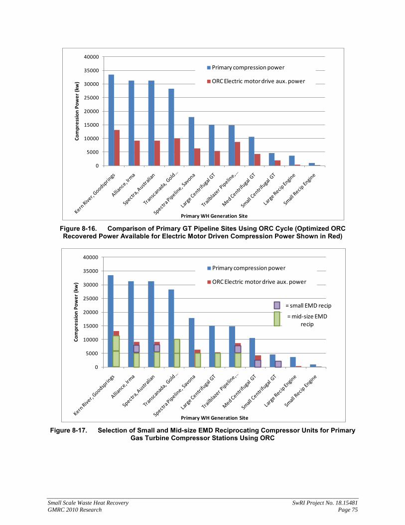
Small Scale Waste Heat Recovery SwRI Project No. 18.15481 GMRC 2010 Research Page 75
Figure 8-16. Comparison of Primary GT Pipeline Sites Using ORC Cycle (Optimized ORC Recovered Power Available for Electric Motor Driven Compression Power Shown in Red)
Figure 8-17. Selection of Small and Mid-size EMD Reciprocating Compressor Units for Primary
Gas Turbine Compressor Stations Using ORC
0
5000
10000
15000
20000
25000
30000
35000
40000
Com
pres
sion
Pow
er (k
w)
Primary WH Generation Site
Primary compression power
ORC Electric motor drive aux. power
0
5000
10000
15000
20000
25000
30000
35000
40000
Com
pres
sion
Pow
er (k
w)
Primary WH Generation Site
Primary compression power
ORC Electric motor drive aux. power
= small EMD recip
= mid-size EMD recip

Small Scale Waste Heat Recovery SwRI Project No. 18.15481 GMRC 2010 Research Page 76
8.16.3 Cost Considerations
The electric motor drive/ ORC option will require a large capital investment and may have additional maintenances costs compared to other ideas. This concept has a couple of cost advantages over traditional steam-based Rankine or organic Rankine cycles. The power generated by the recovery cycle is used as the peaking make-up power via the electric motor. The concept can take advantage of the offset in electrical power rates for high demand periods or non-planned power requests. If sized properly and designed with modern electric motors, the initial capital investment for the additional motor drive package may be fairly small compared to the cost investment of the organic Rankine cycle. In other words, the concept does not require significantly more investment that the standard waste heat recovery option for gas turbine drives. The other major cost advantage to this concept is the use of the compressors and drivers at the best efficiency. The primary driver can be used to supply baseload compression power and designed to match its highest efficiency with this operating point. The variable speed electric motor driven reciprocating compressor supplies the intermittent power at a relatively high efficiency by matching capacity through speed turndown (instead of less efficient recycle or unloading schemes) [71].
8.16.4 Impact on Station
This concept allows the primary compression driver and compressor unit to operate as usual. However, the unit may need to be sized such that it is capable of making up the intermittent maximum and minimum power/ flow rates in the event that the smaller motor driven package (fed by the recovered waste heat/ Rankine cycle) were to fail or not provide adequate power.
8.16.5 Scoring
Criteria Score Reasoning
Capital cost 1 ORC plus one or more EMD/ variable speed recips will be expensive despite using large amounts of waste heat
TRL 4 All components are commercially ready and proven on existing pipeline compressor stations, system packaging must be done to reduce cost
Impact on station 4 Failure of ORC to supply EMD power will require primary driver to make up load, impacts efficiency as well but does not shutdown station
Payback 3 High potential savings by supplying power for peaking unit to avoid high cost electrical rates during peak demand periods, also efficiency savings
Maintenance 2 Expect monthly maintenance items for ORC
Reliability 3 Motor and variable speed options are also rated very high (esp. VS hydraulic type drives); ORC has expected system failure rate of 1-5 years
Operation/ training 2 Motor drive requires additional electrical training (and possibly VFD)
Permitting 2 Depends on selection of steam or organic fluid, may require back-up electrical power from grid (based on operator preference for back-up load)

Small Scale Waste Heat Recovery SwRI Project No. 18.15481 GMRC 2010 Research Page 77
Criteria Score Reasoning
Efficiency Improvement 5 Major efficiency savings possible by designing recip for variable speed to match intermittent load and being able to operate primary GT at high efficiency
Environmental Benefit 3 Creation of additional compression power without increased emissions
Auxiliary Benefit 3
Reduced start-ups and shutdowns for primary driver and possibly reliability improvement gained by operating primary GT drive at nearly constant operating point
Weighted Average 2.97 8.17 Thermoelectrics 8.17.1 Description
Thermoelectric (TE) devices are devices capable of converting thermal energy directly to electrical energy and vice versa. This phenomenon is described by the Seebeck or Peltier effect. These devices have the capability of converting part of the energy in the exhaust gases to usable electricity by incorporating a thermoelectric generator (TEG). The process works by having a temperature differential across the device. As heat energy is transmitted through the device, an electrical current is produced. Therefore, in order to create electricity, one surface of the TEG must be subjected to the high temperature energy of the waste heat, and the opposite surface must be cooled. Cooling can either be provided by exposure to ambient air to a forced convection with a heat exchanging element or by using a thermal cooling fluid. Generally speaking, more electricity is produced as the temperature differential between the two surfaces is increased [5].
8.17.2 Equipment Requirements
An installation similar to what is shown in Figure 8-18 would be the likely implementation. The reason for the heat exchanger in this setup, instead of just a direct contact of the TEG with the exhaust stream, is that because of current limitations with commercial products, TEs have maximum temperatures that are exceeded by all engine exhausts. There is current research work, however, that promises to yield TE devices with much higher limits and overall efficiencies.
Figure 8-18: Possible Installation of a Thermoelectric Generator (TEG) to Harvest Waste Heat

Small Scale Waste Heat Recovery SwRI Project No. 18.15481 GMRC 2010 Research Page 78
The TEG shown in the figure is actually an array of TE devices. In order to obtain levels of electricity that are useful, it is necessary to wire a number of TEs together in parallel and/or series to create the voltages and currents that can be used in most standard devices. The shape and size of the array are dependent on the waste heat available, the required energy output, and the unique manufacturer design.
8.17.3 Cost Analysis
Until current research is completed and newer TEG designs are made available through industry, the major disadvantage of TEGs is the low efficiencies. Some devices can be found that have efficiencies as high at 8-10%, but more common efficiencies are closer to 4%. However, even the higher efficiency units can be relatively inexpensive. One specific TEG, which costs approximately $300, is capable of producing nearly 25 watts of electricity by using 405 watts of thermal energy (thermal efficiency of 6.19%) at 250° C in an ambient temperature of 32° C [72]. At 15¢/kWh and assuming you used all 25 watts of energy in an hour, you would save .375¢/hr, which is almost 9¢/day, and assuming operation for 50% of the year would be an annual savings of almost $17 in electrical costs.
There are some projections that with the advancing research on TE devices, efficiency could get as high 20-30% [73]. In which case, the unit above (using the same energy) could produce as much as 81 watts. This, with similar assumptions, would create an annual savings of almost $55.
8.17.4 Scoring
8.17.4.1 Thermoelectrics
Criteria Score Reasoning
Capital Cost 2
The cost of the TEG units is in the $100-$1000 range, but cost of a heat exchanger could push overall system cost in the $10K range. This system has a low waste heat usage.
TRL 4 Currently, TEG units are available; however, research is still ongoing to make them more efficient and applicable to usage
Impact on station 5 Failure of units to produce electricity simply means more electricity must be purchased from local grid
Payback 1 Low cost savings due to poor efficiency make payback nearly impossible
Maintenance 4 Likely will have yearly maintenance for heat exchangers; TEGs have no moving parts, so little to no maintenance required
Reliability 4 TEGs are typically very reliable as they are solid state, but heat exchanger failure rates are on the order of greater than 5 years
Operation/ Training 4 No additional operation/training considerations Permitting 5 No special permitting required for system
Efficiency improvement 1 Low-efficiency of current TEGs results in minimal improvement to unit efficiency
Environmental benefit 3 Production of emission-free power

Small Scale Waste Heat Recovery SwRI Project No. 18.15481 GMRC 2010 Research Page 79
Criteria Score Reasoning
Auxiliary benefit 2 Temperature limit of TEGs makes units ideal as a secondary WHR by using exhaust gases after a primary WHR system
Weighted Average 3.08 8.18 Engine Inlet Cooling 8.18.1 Description
In efforts to improve engine efficiency, cooling of the air going into the inlet of a gas turbine is one possibility. Depending on engine design and original conditions, it is theoretically possible to improve overall efficiency, resulting in savings on overall fuel costs. However, these savings can quickly be diminished by using cooling sources that rely on additional energy costs.
Instead, it is possible to use waste heat to perform cooling of the inlet air by using an absorption chiller, or similar type of technology.
8.18.2 Equipment Requirements
Although there are numerous specific application scenarios, the general concept of using the waste heat from a turbine to perform pre-inlet cooling is shown in Figure 8-19.
In this specific scenario, a heat exchanger is used to take heat from the exhaust gas and transfer it to an absorption chiller by way of a thermal fluid. Through the internal process of the absorption chiller, this heat is used to cool a second thermal fluid, which is used in a second heat exchanger to cool the ambient air before its entry into the inlet of the gas turbine. Therefore, this implementation scenario would require an absorption chiller system, two heat exchangers, and all of the necessary secondary equipment for fluid transfer (piping, pumps, etc.).
Figure 8-19: Diagram Illustrating Use of an Absorption Chiller for Pre-Cooling

Small Scale Waste Heat Recovery SwRI Project No. 18.15481 GMRC 2010 Research Page 80
Implementation of this concept would require that the unit be shut down, and depending on the specifics of the chiller, some additional safety precautions might be necessary, and additional maintenance will be required. And, should the chilling unit fail, the unit will still be able to operate, just not at the higher efficiency.
8.18.3 Cost Analysis
The cost of such a system is difficult to develop because the absorption chiller and heat exchangers really need to be designed for the specific turbine it will be implemented on. The same is also true in determining the cost savings. However, assuming theoretical operation for a 1,600 hp gas turbine, it was calculated that by dropping the inlet temperature by 20° F (from 90° F to 70° F, which is attainable for most any unit by using its exhaust heat energy), an efficiency improvement of just over 1% was attainable, which would result in approximately $11,000 fuel savings per year. This amount of cooling for this unit would take approximately 25 TR, and an absorption chilling unit that is capable of 30 TR would cost in the range of $35,000. Depending on the design of the turbine and original operating conditions, actual efficiency improvement and savings could vary drastically. So application of this waste heat recovery method would have to be judged on an individual unit basis [5 – 11].
8.18.4 Scoring
8.18.4.1 Turbine Inlet Cooling
Criteria Score Reasoning
Capital Cost 2 Set of heat exchangers and chiller unit that use lower amounts of waste heat
TRL 5 All equipment is currently widely available
Impact on Station 4 Failure of equipment will reduce efficiency to original level, but no shut-down would be mandated
Payback 4 Fuel cost savings should allow recoup of equipment costs
Maintenance 3 Chilling unit will likely require additional maintenance scheduling
Reliability 4 Chilling unit reliability is not as well documented as heat exchangers
Operation/ Training 3 Additional training on chilling unit will likely be required
Permitting 3 Depending on chilling unit, additional permitting may be required
Efficiency Improvement 3 Process change will increase efficiency Environmental Benefit 5 Reduced emissions because of improved combustion Auxiliary Benefit 3 Extra cooling could be used to cool product stream Weighted Average 3.71


![8. Rankine Cycle · 2018-01-13 · Thermodynamics 8. Rankine Cycle 2 / 113 ... Heat is added in the boiler, ... [Solution] From the steam tables, h](https://img.pdfslide.us/doc/110x75/5b7b31377f8b9a004b8c2deb/8-rankine-2018-01-13-thermodynamics-8-rankine-cycle-2-113-heat-is.jpg)