Embed Size (px)
Citation preview

®Copyright 2010 July All Rights Reserved Version 2.0
The information contained in this document is subject to change without notice. We make no warranty of any kind with regard to this material, including, but not limited to, the implied warranties of merchantability and fitness for a particular purpose. We shall not be liable for errors contained herein or for incidental or consequential damages in connection with the furnishing, performance, or use of this material.
This document contains proprietary information that is protected by copy right. All rights are reserved. No part of this document may be photocopied, reproduced or translated to another language without the prior written consent of the manufacturer.
TRADEMARK
Intel®, Pentium® and MMX are registered trademarks of Intel® Corporation. Microsoft® and Windows® are registered trademarks of Microsoft Corporation.
S m a l l f o o t p r i n t & E l e g a n t
1
Main Board CPU
IT7000V0-15 Intel® Pentium® Processor 2117U (2M Cache, 1.80 GHz)
Chipset Intel® HM70 Express
System Memory Socket-type RAM device, 204PIN SO-DIMM DDR3 1333 / 1600 RAM, up to 8GB
Graphic Memory Shared system memory up to 256MB
LCD Panel IT7000V0-15
Panel Size
Maximum Resolution
Brightness
Contrast Ratio
Response Time
View Angles (H/V)
Touch Panel
15”
1024 x 768
250 cd/m1 700 : 1
16 ms
150 / 120
Five Wires Resistive Touch or Projected Capacitive Touch
Storage HDD 2.5” SATAIII interface
Expansion Socket One Mini-PCIE or One Msata II
PowerPower Adaptor Input AC 100-240V 2.5A 50/60Hz, Output DC 12V 6.66A
I / OUSB Six
Serial Four COM ports with RJ-45 Connector
Pin 9 with 5V / 12V power selectable
Parallel One LPT with adaptor cable
LAN One
2nd VGA Output One with optional adaptor cable
PS/2 One
1

2
Audio One Earphone & One Microphone
Cash Drawer One with optional adapter
Control/Indicator Power Button One
LED Indicators Power (Green), HDD (Red), LAN(Orange)
Optional Peripherals Magnetic Card Reader ISO Track 1/2/3, USB interface
VFD customer display 20 x 2 characters, RS-232 interface
Dimensions IT-7000V0-15 358(W) X 367(L) X 173(H) mm
Environment Operating Temperature 0°C ~ 40°C ( 32°F ~ 104°F )
Storage Temperature - 20°C ~ 60°C ( - 4°F ~ 140°F )
Operating Humidity 10% - 80% RH non condensing
Storage Humidity 10% - 80% RH non condensing
Model Number IT7000VX – SS Intel® Pentium® Processor 2117U
X : M --- Shinny Black housing
Q --- Dull Black housing
W – Shinny White housing
SS: 15 --- 15"TFT LCD

3
If any item is missing, please contact your sale agent immediately.
Take the system unit out from the carton. Remove the unit by carefully holding the foam inserts and remove slowly to
protect the system. The following items should be found in the carton:
1. CD that including all driver and manual
2. The System
. Power Adaptor 4. AC Power Cord
5. Printer Port conversion cable 6. Two RS-232 port
conversion cables
2

4
Please unplug the AC power of the adapter before opening any part of the system. Since the
standby power is always on after the adapter is plugged in. It may cause permanent damage
to your system when you open any part of it.
Front View
Side USB
Power HDD LAN Power Button
Rear View
Slot for installing Magnetic Card Reader (optional)
Hard Disk Cover
Cable Cover
Slot for installing Custom Display (optional)
3

5
How to open the connector bezel Please unplug the AC power of the adapter before opening any part of the system.
Since the standby power is always on after the adapter is plugged in.
It may cause permanent damage to your system when you open any part of it.
As illustrated in the following,
Move these two sides upward Push the locker downward
Move these two sides upward
6
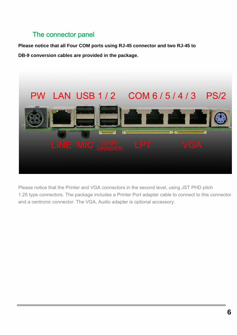
The connector panel Please notice that all Four COM ports using RJ-45 connector and two RJ-45 to
DB-9 conversion cables are provided in the package.
Please notice that the Printer and VGA connectors in the second level, using JST PHD pitch 1.25 type connectors. The package includes a Printer Port adapter cable to connect to this connector and a centronic connector. The VGA, Audio adapter is optional accessory.
7
Please unplug the AC power of the adapter before opening any part of the system. Since the
standby power is always on after the adapter is plugged in. It may cause permanent damage
to your system when you open any part of the system.
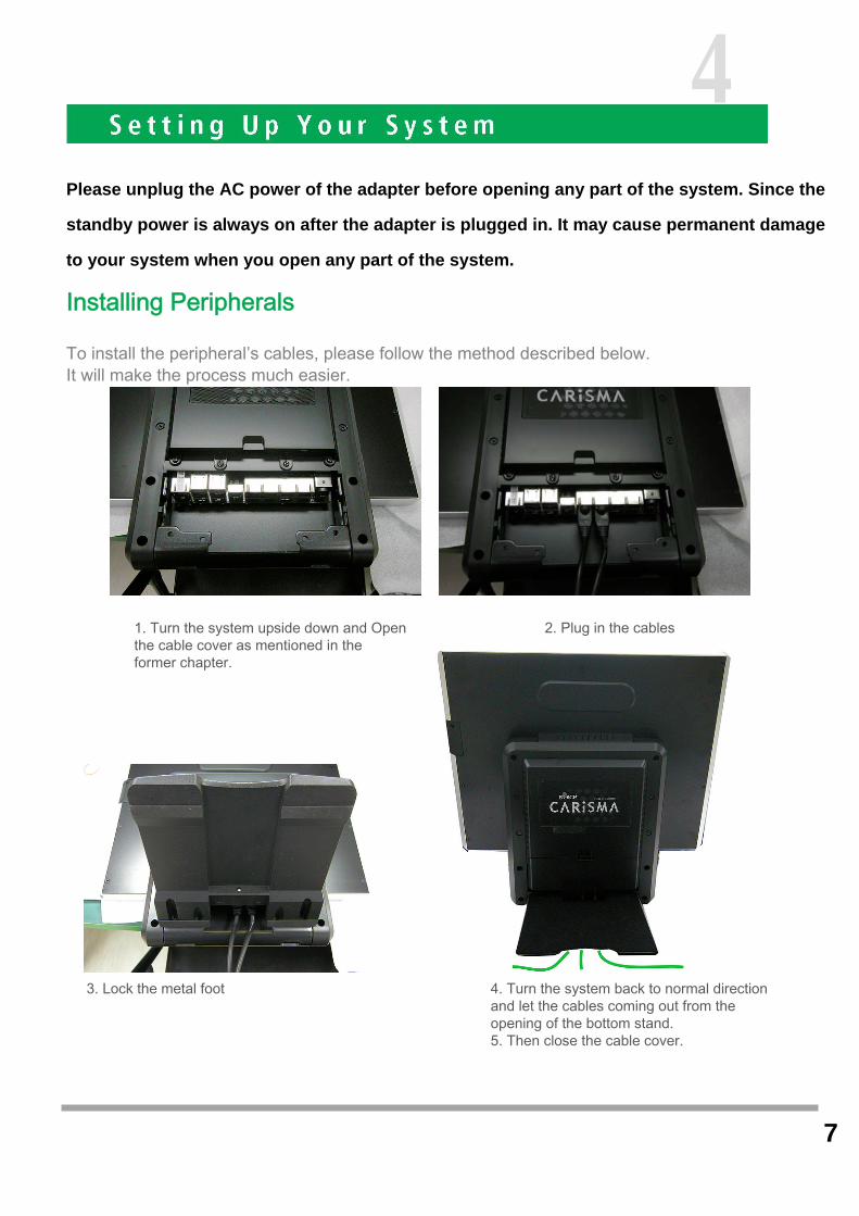
Installing Peripherals
To install the peripheral’s cables, please follow the method described below. It will make the process much easier.
1. Turn the system upside down and Open the cable cover as mentioned in the former chapter.
2. Plug in the cables
3. Lock the metal foot 4. Turn the system back to normal direction and let the cables coming out from the opening of the bottom stand. 5. Then close the cable cover.
4

8
Installing Magnetic Card Reader (MSR)
1. Turn the system upside down 2. Open the cover of MSR cable
3. Connect the cable to MSR 4. Lock the screw to mount MSR
9
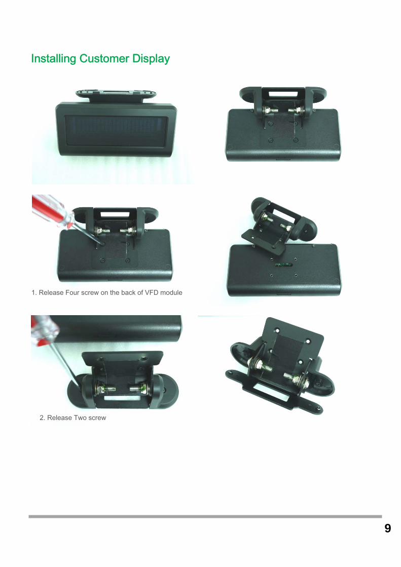
Installing Customer Display
1. Release Four screw on the back of VFD module
2. Release Two screw

10
3. Release the screws on the VFD module
4. Release the VFD board
5. Turn the system upside down
6. Open the VFD cover by fingernail

11
7. Pass the signal line through the middle of the lower hinge mount hole
8. Pass the signal line through the middle of the upper of hinge mount hole
9. Lock the hinge mount by screw
10. Pass the signal line through the middle of the VFD base
11. Connect the signal line with VFD board

12
12. Lock the VFD board by screws
13. Close the VFD cover Attention: Make sure latches are securely
15. Cut two plastic sheets 14. Lock the VFD cover with VFD base

13
16. Install hinge cover 17. Lock the hinge cover by screw
18. Lock the VFD module with hinge mount 19. Taped

14
Installing Hard Disk
Please unplug the AC power of the adapter before opening the hard disk cover. Since the
standby power is always on after the adapter is plugged in. It may cause permanent damage
to your system when you open any part of the system.
1. Release these two screws of the hard disk cover.
2. After remove the hard disk cover, you will
find the 2.5” hard disk
15
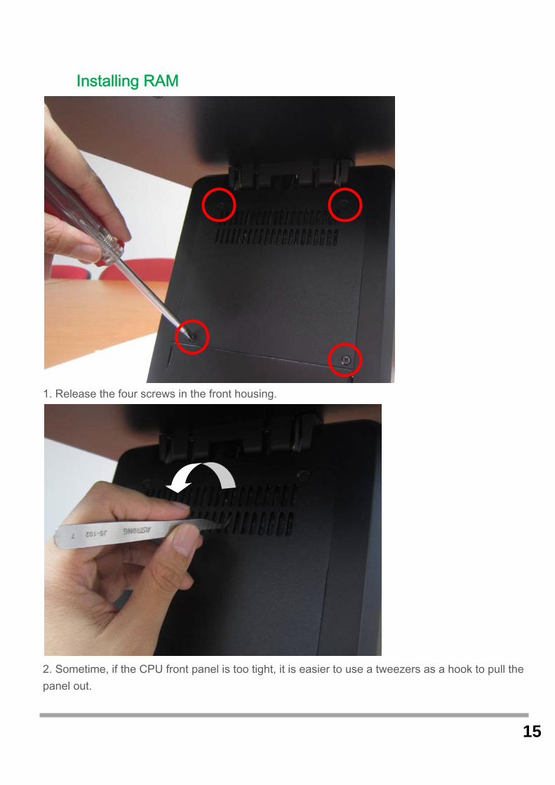
Installing RAM
1. Release the four screws in the front housing.
2. Sometime, if the CPU front panel is too tight, it is easier to use a tweezers as a hook to pull the panel out.
16
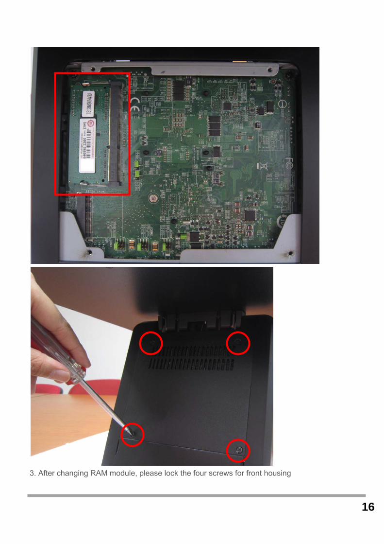
3. After changing RAM module, please lock the four screws for front housing

17
Introducing BIOS
Notice! The BIOS options in this manual are for reference only. Different configurations may lead to difference in BIOS screen and BIOS screens in manuals are usually the first BIOS version when the board is released and may be different from your purchased motherboard. Users are welcome to download the latest BIOS version form our official website.
The BIOS is a program located on a Flash Memory on the motherboard. This program is a bridge
between motherboard and operating system. When you start the computer, the BIOS program will
gain control. The BIOS first operates an auto-diagnostic test called POST (power on self test) for all
the necessary hardware, it detects the entire hardware device and configures the parameters of
the hardware synchronization. Only when these tasks are completed done it gives up control of
the computer to operating system (OS). Since the BIOS is the only channel for hardware
and software to communicate, it is the key factor for system stability, and in ensuring that your
system performance as its best.
Entering Setup
Power on the computer and by pressing <Del> immediately allows you to enter Setup. If the
message disappears before your respond and you still wish to enter Setup, restart the system to
try again by turning it OFF then ON or pressing the “RESET” button on the system case. You may
also restart by simultaneously pressing <Ctrl>, <Alt> and <Delete> keys. If you do not press
the keys at the correct time and the system does not boot, an error message will be
displayed and you will again be asked to Press <Del> to enter Setup
5
18
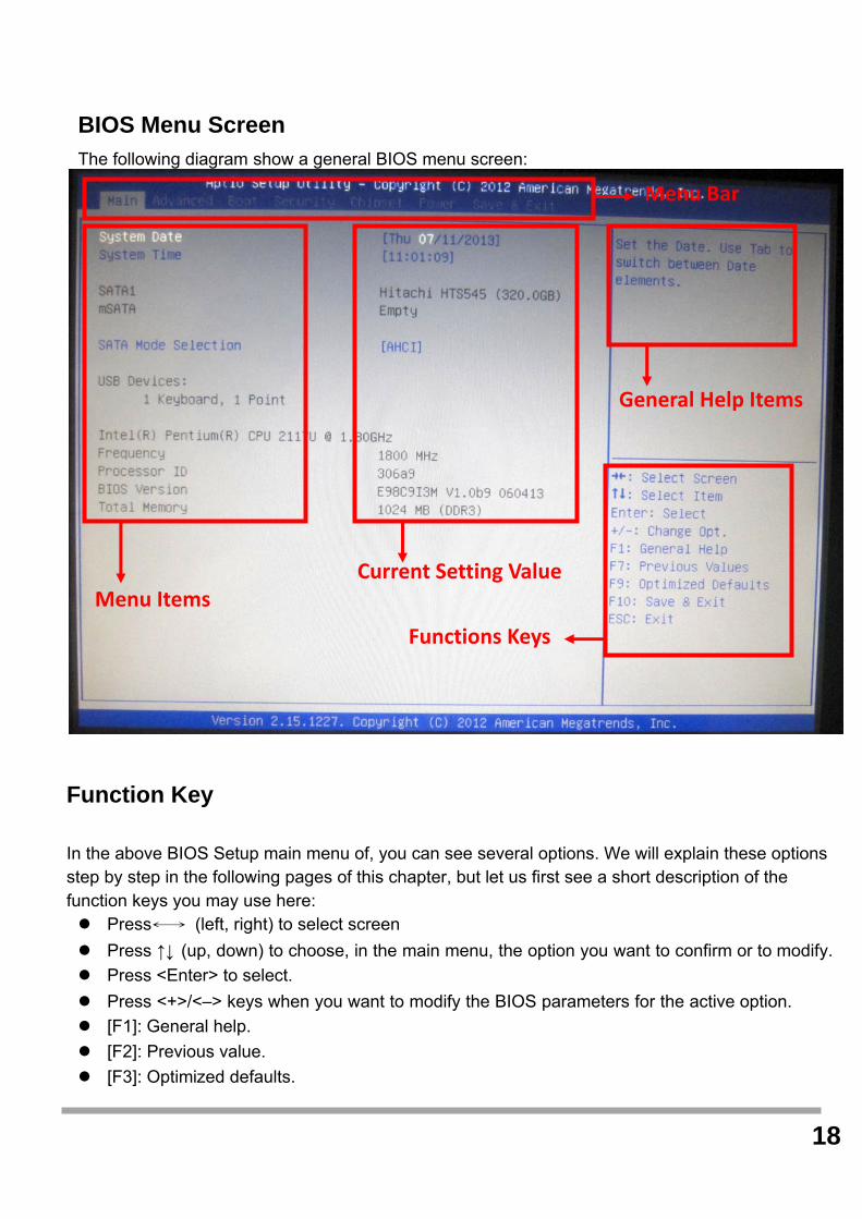
BIOS Menu Screen The following diagram show a general BIOS menu screen:
Function Key
In the above BIOS Setup main menu of, you can see several options. We will explain these options step by step in the following pages of this chapter, but let us first see a short description of the function keys you may use here: Press←→ (left, right) to select screen
Press ↑↓ (up, down) to choose, in the main menu, the option you want to confirm or to modify.
Press <Enter> to select.
Press <+>/<–> keys when you want to modify the BIOS parameters for the active option.
[F1]: General help.
[F2]: Previous value.
[F3]: Optimized defaults.
Menu Bar
Menu Items Current Setting Value
General Help Items
Functions Keys

19
[F4]: Save & Reset.
Press <Esc> to quit the BIOS Setup.
Getting Help Main Menu The on-line description of the highlighted setup function is displayed at the top right corner the
screen.
Status Page Setup Menu/Option Page Setup Menu Press F1 to pop up a small help window that describes the appropriate keys to use and the
possible selections for the highlighted item. To exit the Help Window, press <Esc>.
Menu Bar
There are six menu bars on top of BIOS screen:
Main To change system basic configuration
Advanced To change system advanced configuration
Chipset To change chipset configuration
Boot To change boot settings
Security Password settings
Save & Exit Save setting, loading and exit options.
User can press the right or left arrow key on the keyboard to switch from menu bar. The
selected one is highlighted.
20
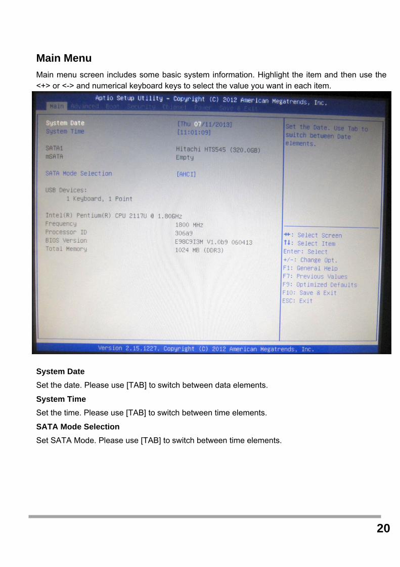
Main Menu
Main menu screen includes some basic system information. Highlight the item and then use the <+> or <-> and numerical keyboard keys to select the value you want in each item.
System Date
Set the date. Please use [TAB] to switch between data elements.
System Time
Set the time. Please use [TAB] to switch between time elements.
SATA Mode Selection
Set SATA Mode. Please use [TAB] to switch between time elements.

21
Advanced Menu
Full Screen logo Display
Enables or disables Quiet Boot option.
Bootup Numlock State
Select the keyboard Number Lock State.
Option ROM Messages Set display mode for Option ROM
PCI/PCIE Device Configuration PCI, PCI-X and PCI Express Settings PCI Latency Timer Value to be programmed into PCI Latency Timer Register EHCI1 Control the USB EHCI (USB 2.0) functions. One EHCI controller must always be enabled.

22
EHCI2 Control the USB EHCI (USB 2.0) functions. One EHCI controller must always be enabled. Legacy USB Support Enables Legacy USB support. Audio Controller Control Detection of the Audio Controller. Launch Onboard Lan OpROM Enables or Disable Boot Option for Legacy Network Devices. Mini-PCIe Slot Select Mini-PCIe or mSATA mode for Mini-PCIe Slot.
CPU Configuration
CPU Configuration Parameters. Active Processor Cores Number of cores to enable in each processor package. Execute Disable Bit XD can prevent certain classes of malicious buffer overflow attacks when combined with a
supporting OS. Intel Virtualization Technology When enabled, a VMM can utilize the additional hardware capabilities provided by Vanderpool
Technology. EIST Enable/Disable Intel SpeedStep.
Super IO Configuration
System Super IO Chip Parameters Serial Port 1 Use this item to enable or disable serial port.
Change Settings Use this item to select an optimal setting for super IO device.
Serial Port 2 Use this item to enable or disable serial port.
Change Settings Use this item to select an optimal setting for super IO device.
Serial Port 3 Use this item to enable or disable serial port.
Change Settings Use this item to select an optimal setting for super IO device.
Serial Port 4 Use this item to enable or disable serial port.
Change Settings Use this item to select an optimal setting for super IO device.
23
Serial Port 5 Use this item to enable or disable serial port.
Change Settings Use this item to select an optimal setting for super IO device.
Serial Port 6 Use this item to enable or disable serial port.
Change Settings Use this item to select an optimal setting for super IO device.
Parallel Port Use this item to enable or disable parallel port (LPT/LPE).
Change Settings Select an optimal setting for Super IO device. Device Mode Change the Printer Port mode.
FIFO Mode Set FIFO Mode. Shared IRQ Mode Level/Edge. Watch Dog Timer Watch Dog Timer.
H/W Monitor
Monitor hardware status Thermal Shutdown Use this item to enable or disable thermal shutdown.
Smart FAN Configuration
Smart FAN Configuration Smart CPUFAN1 and CPUFAN2 Use this item to enable or disable FAN function.

24
Boot Menu
Boot Option #1
The optional settings are: [Windows Boot Manager]; [Disabled].
Hard Drive BBS Priorities
Set the order of the legacy devices in this group.

25
Security Menu
Security menu allow users to change administrator password and user password settings.
PCH-FW Configuration
Configure Management Engine Technology Parameters.
Intel(R) Anti-Theft Technology Configuration
Disabling Intel(R) AT Allow user to login to platform. This is strictly for testing only. This does not disable Intel(R) AT Services in ME.
Serial Port Console Redirection
Serial Port Console Redirection.
26
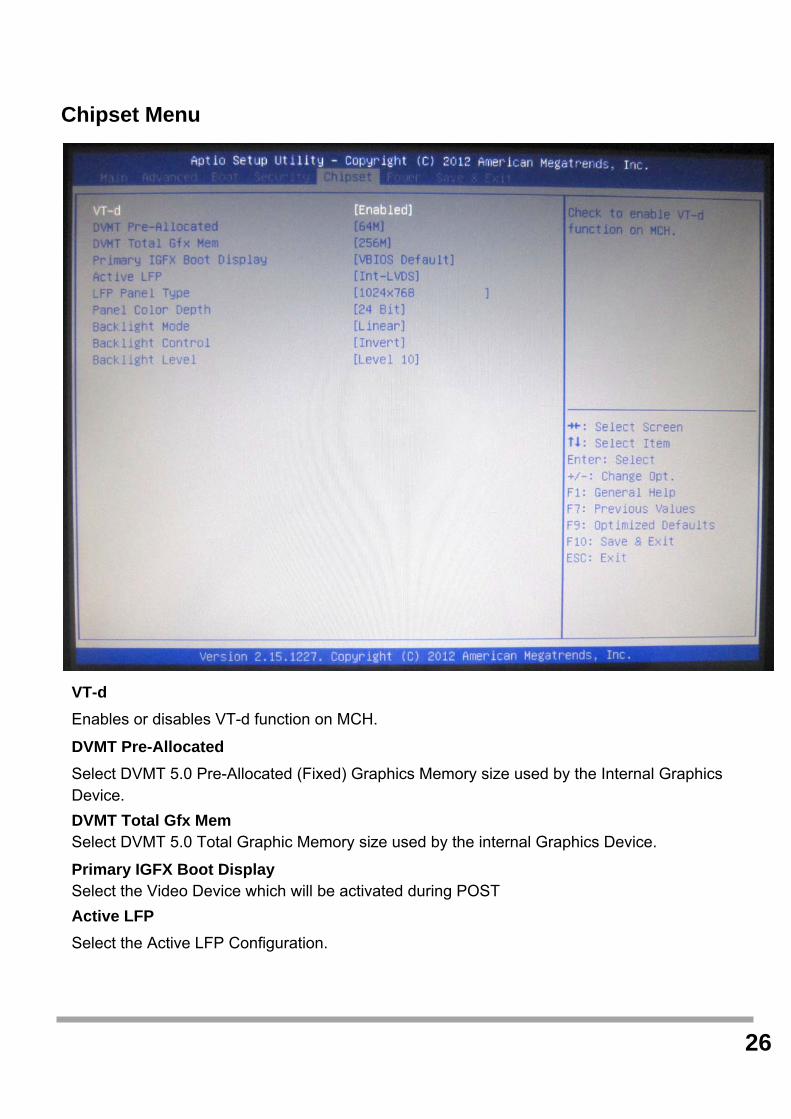
Chipset Menu
VT-d
Enables or disables VT-d function on MCH.
DVMT Pre-Allocated
Select DVMT 5.0 Pre-Allocated (Fixed) Graphics Memory size used by the Internal Graphics Device.
DVMT Total Gfx Mem Select DVMT 5.0 Total Graphic Memory size used by the internal Graphics Device.
Primary IGFX Boot Display Select the Video Device which will be activated during POST
Active LFP
Select the Active LFP Configuration.

27
LFP Panel Type
Select internal panel type.
Panel Color Depth Select internal panel color depth.
Backlight Mode Backlight Mode Selection
Backlight Control Backlight Control Selection
Backlight Level Backlight Level Selection

28
Power Menu
ACPI Sleep State
Select ACPI sleep state the system will enter when the SUSPEND button is pressed.
Restore AC Power Loss
Select AC power state when power is re-applied after a power failure.
Deep S5 Configure the DeepSx Mode Configuration.
Advanced Resume Events Control
USB from S3/S4 Main switch Resume on USB from S3/S4
PCIE PWE
Resume on PCIE PME.

29
Ring
Enabled or Disabled Wake On Ring.
RTC Enable or Disable System wake on from S3/S4/S5 alarm event.
30
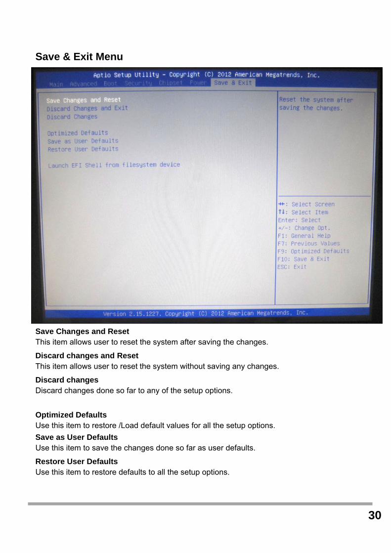
Save & Exit Menu
Save Changes and Reset This item allows user to reset the system after saving the changes.
Discard changes and Reset This item allows user to reset the system without saving any changes.
Discard changes Discard changes done so far to any of the setup options.
Optimized Defaults Use this item to restore /Load default values for all the setup options.
Save as User Defaults Use this item to save the changes done so far as user defaults.
Restore User Defaults Use this item to restore defaults to all the setup options.

31
Launch EFI Shell from filesystem device
This item is used for attempts to launch EFI shell application from one of the available file system devices.
32
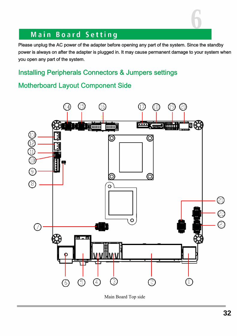
Please unplug the AC power of the adapter before opening any part of the system. Since the standby power is always on after the adapter is plugged in. It may cause permanent damage to your system when you open any part of the system.
Installing Peripherals Connectors & Jumpers settings
Motherboard Layout Component Side
Main Board Top side
6

33

34
Connector: JUSB1/2 Type: DF13 10-pin pitch=1.25mm
Pin Description Pin Description
1 5VSB 2 5VSB
3 USB4N/6N 4 USB5N/7N
5 USB4P/6P 6 USB5P/7P
7 GND 8 GND
9 GND 10 N/C
10 2
9 1
35
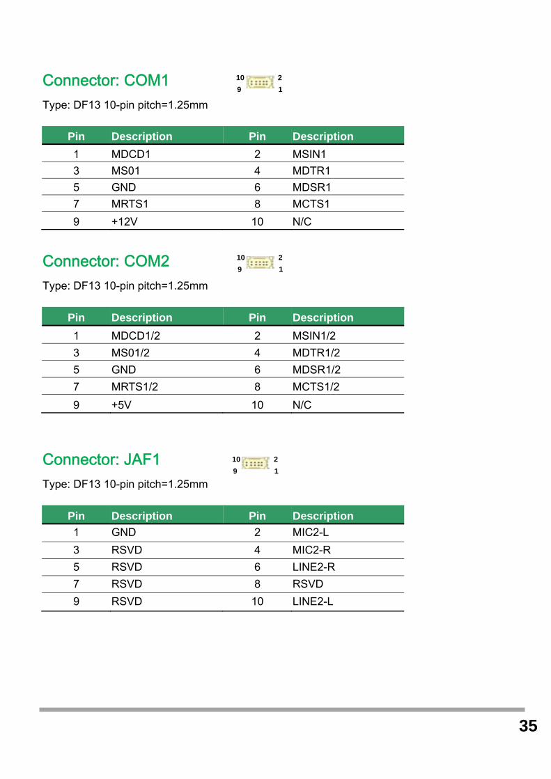
Connector: COM1 Type: DF13 10-pin pitch=1.25mm
Connector: COM2 Type: DF13 10-pin pitch=1.25mm
Pin Description Pin Description
1 MDCD1/2 2 MSIN1/2
3 MS01/2 4 MDTR1/2
5 GND 6 MDSR1/2
7 MRTS1/2 8 MCTS1/2
9 +5V 10 N/C
Connector: JAF1 Type: DF13 10-pin pitch=1.25mm
Pin Description Pin Description
1 GND 2 MIC2-L
3 RSVD 4 MIC2-R
5 RSVD 6 LINE2-R
7 RSVD 8 RSVD
9 RSVD 10 LINE2-L
Pin Description Pin Description
1 MDCD1 2 MSIN1
3 MS01 4 MDTR1
5 GND 6 MDSR1
7 MRTS1 8 MCTS1
9 +12V 10 N/C
10 2
9 1
10 2
9 1
10 2
9 1

36
5 1
Connector: JINV1 Type: 5-pin LVDS Power Header
Pin Description
1 +12V
2 CTLBKL
3 GND
4 GND
5 ENABKL
Connector: JLVDS1 Type: onboard 40-pin connector for LVDS connector Connector model: HIROSE DF13-40DP-1.25V
Pin Description Pin Description
2 LCDVCC 1 LCDVCC
4 GND 3 GND
6 ATX0- 5 BTX0-
8 ATX0+ 7 BTX0+
10 GND 9 GND
12 ATX1- 11 BTX1-
14 ATX1+ 13 BTX1+
16 GND 15 GND
18 ATX2- 17 BTX2-
20 ATX2+ 19 BTX2+
22 GND 21 GND
24 ACLK- 23 BTX3-
26 ACLK+ 25 BTX3+
28 GND 27 GND
30 ATX3- 29 BCLK-
32 ATX3+ 31 BCLK+
34 GND 33 GND
36 DDCPCLK 35 N/C
38 DDCPDATA 37 N/C
40 N/C 39 N/C
40 2
1 39

37
4 1
Connector: JFP1 Type: DF13 10-pin pitch=1.25mm
Pin Description Pin Description
1 PWRBT- 2 PWRBT-
3 LANLED- 4 LANLED+
5 HDLED 6 HDLED+
7 PWRLED 8 PWRLED+
9 Reset+ 10 Reset-
Connector: JHDDPWR1 Type: 4-pin connector for +5V/+12V output
Pin Description Pin Description
1 +12V 2 Ground
3 Ground 4 +5V
Connector: JPLT Type: DF14 25-pin pitch=1.25mm
Pin Description Pin Description
1 -PSTB 2 AFD
3 PRD0 4 ERR
5 PRD1 6 INIT
7 PRD2 8 SLIN
9 PRD3 10 GND
11 PRD4 12 GND
13 PRD5 14 GND
15 PRD6 16 GND
17 PRD7 18 GND
19 ACK 20 GND
21 BUSY 22 GND
23 PE 24 GND
25 SLCT
10 2
9 1
25 1

38
Connector: JVGA1 Type: DF14 25-pin pitch=1.25mm
Pin Description Pin Description
1 BR 2 5VSB
3 BG 4 GND
5 BB 6 N/C
7 N/C 8 CDA
9 GND 10 HSYNC
11 GND 12 VSYNC
13 GND 14 CLK
15 GND
Connector: JCDW1 Type: DF14 25-pin pitch=1.25mm
Pin Description Pin Description
1 GND 2 Drawer kick-out drive signal
3 Drawer Open/closed signal 4 24VDC
5 Drawer kick-out drive signal 6 Drawer kick-out Open/closed signal ground≤1A/24V
Connector: JCOM1(COM3)/JCOM2(COM4) /JCOM3(COM5 & COM6)
Type: onboard 3 x 2-pin header
JP1/JP2 Mode
5-6 Standard COM Port
3-4 Pin9 with 12V signal
1-2 Pin9 with 5V signal
Default setting
15 1
1 5
2 6
6 1

39
Connector: JCOMS1
Type: Onboard 3-pin jumper
Normal Operation Mode
1-2 Clear CMOS
2-3 Normal Operation
Default setting
Connector: JAT_ATX11
Type: Onboard 3-pin jumper
Normal Operation Mode
1-2 AT Mode
2-3 ATX Mode
Default setting
1 3
1 3

40
Character Font Table A. Control code set B. U.S.A. font set
7
41
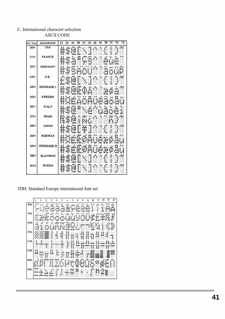
C. International character selection ASCII CODE
3DH: Standard Europe international font set

42
3EH: Multingual international font set
3FH: Portuguese international font set

43
40H: Canadian French international font set
41H: NORDIC internatinal font set

44
42H: RUSSIA font set
43H: SLAVONIC Font set

45
44H: Katakana font set
System Commands Command Format
Command List
A. Set Baud Rate
COMMAND: B
COMPUTER:EOT SOH 'B' 'BAUD RATE' 'N' ETB
ASCII (04H) (01H)(42H) (31H~37H)(4EH)(17H)
Byte 1 1 1 1 1 1
DISPLAY: ACK (or NACK if failed)
ASCII (06H) (15H)
Byte 1 1

46
Note: Baud rates
31H: 9600
32H: 4800
33H: 2400
34H: 1200
35H: 600
36H: 300
37H:19200
B. Select international code table
COMMAND: I
COMPUTER:EOT SOH 'I' 'CHAR' ETB
ASCII(04H)(01H)(49H)(30H~44H)(17H)
Byte 1 1 1 1 1
DISPLAY: ACK (or NACK if failed)
ASCII (06H) (15H)
Byte 1 1
Note : International Character Code
C. Save the current view message
(Save Demo view data)
COMMAND: S
COMPUTER:EOT SOH 'S' 'Layer' ETB
ASCII(04H)(01H)(53H)(31H~33H)(17H)
Byte 1 1 1 1 1
DISPLAY: ACK (or NACK if failed)
ASCII (06H) (15H)
Byte 1 1
Note : 31H: Layer 1 / 32H: Layer 2 / 33H: Layer 3

47
D. Set cursor position
COMMAND: P
COMPUTER: EOT SOH 'P' 'Position' ETB
ASCII (04H) (01H) (50H) (31H~58H) (17H)
Byte 1 1 1 1 1
DISPLAY: ACK (or NACK if failed)
ASCII (06H) (15H)
Byte 1 1
Note: The cursor can be set to the position from 1 to 40
Position 1 means the upper left corner position.
Position 20 means the upper right corner position.
Position 21 means the lower left corner position.
Position 40 means the lower right corner position.
E. Clear display range
COMMAND: C
COMPUTER: EOT SOH 'C' 'START' 'END' ETB
ASCII (04H)(01H)(43H)(31H~58H)(31H~58H)(17H)
Byte 1 1 1 1 1
DISPLAY: ACK (or NACK if failed)
ASCII (06H) (15H)
Byte 1 1
Note: Some part of the current view messages can be
cleared by this COMMAND. It can start clearing
between position 1 and position 40.
F. Display the saved DEMO message
COMMAND: D
COMPUTER: EOT SOH 'D' 'Layer' 'Mode' ETB
ASCII (04H)(01H)(44H)(31H~37H)(31H~33H)(17H)
Byte 1 1 1 1 1
DISPLAY: ACK (or NACK if failed)
ASCII (06H) (15H)
Byte 1 1
Note:
a) There are three layers of saved view messages as described on COMMAND "S"
b) There are two modes of display:
Mode 1 is running the saved messages from right to left, which is a horizontal scroll mode.
Mode 2 is running the saved messages from the lower line to the upper line, which is a vertical scroll mode.
c) For display layers:

48
select 31H means display the message saved on layer 1.
select 32H means display the message saved on layer 2.
select 33H means display the message saved on layer 1+ layer2.
select 34H means display the message saved on layer 3.
select 35H means display the two messages saved on layer 1 + layer 3.
select 36H means display the two messages saved on layer 2 +layer 3.
select 37H means display all the messages saved on layer 1 +layer 2 + layer 3.
d) For display modes,
select 31H means display the message with Mode 1.
select 32H means display the message with Mode 2.
select 33H means display the message with Mode 1+Mode 2.
For this Demo display function, you must have saved the message by COMMAND "S" previously, For example, select
37H for displaying layers and select 33H for displaying modes, DSP would display all the three messages saved on
layer 1+ layer 2 + layer 3 with both Mode 1 + Mode 2 displaying modes.
e) Any new message from the computer would stop this Demo
display function and DSP would display that new message from the computer.
G. Select the Command Mode
COMMAND: M
COMPUTER: EOT SOH 'M' 'Mode' ETB
ASCII (04H) (01H) (4DH)(30H~38H) (17H)
Byte 1 1 1 1 1
DISPLAY: ACK (or NACK if failed)
ASCII (06H) (15H)
Byte 1 1
Note: Command Modes Selection
H. Set all default
COMMAND: X
COMPUTER: EOT SOH 'X' ETB
ASCII (04H) (01H) (58H) (17H)
Byte 1 1 1 1
49
Transmission method Each ASCII character is transmitted with
1 start bit
8 data bits
1 stop bit
No parity
Note: You may generate your own application software to run the display according to the standard
RS-232C communication protocols and the SOFTWARE CONTROL information listed on this chapter.
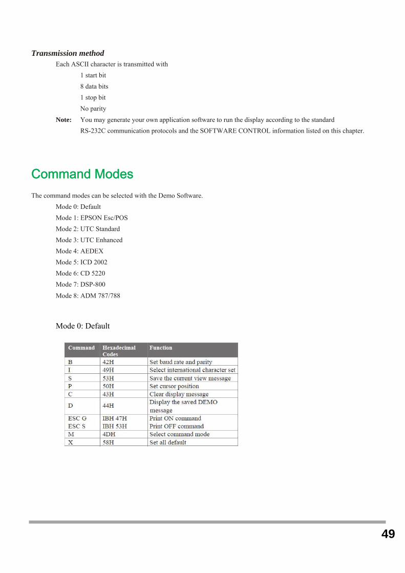
Command Modes The command modes can be selected with the Demo Software.
Mode 0: Default
Mode 1: EPSON Esc/POS
Mode 2: UTC Standard
Mode 3: UTC Enhanced
Mode 4: AEDEX
Mode 5: ICD 2002
Mode 6: CD 5220
Mode 7: DSP-800
Mode 8: ADM 787/788
Mode 0: Default
50
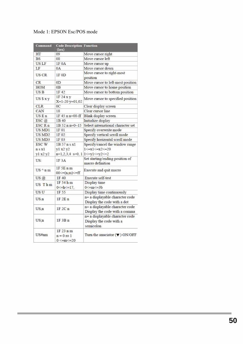
Mode 1: EPSON Esc/POS mode
51
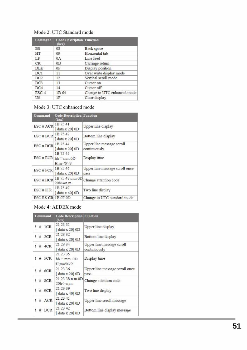
Mode 2: UTC Standard mode
Mode 3: UTC enhanced mode
Mode 4: AEDEX mode
52
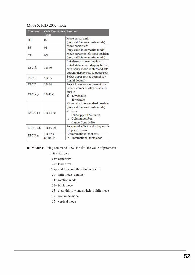
Mode 5: ICD 2002 mode
REMARK)* Using command "ESC E r Φ", the value of parameter:
r 58= all rows
55= upper row
44= lower row
Φspecial function, the value is one of
30= shift mode (default)
31= rotation mode
32= blink mode
33= clear this row and switch to shift mode
34= overwrite mode
35= vertical mode

53
Mode 6: CD 5220 standard mode

54
Mode 7: DSP-800 mode
Mode 8: ADM 787/788 mode

55
CE MARK
This device compiles with the requirements of the EEC directive 89/336/EEC with regard to
“Electromagnetic compatibility” and 73/23/EEC “Low Voltage Directive”
FCC This device complies with part 15 of the FCC rules. Operation is subject to the following two
conditions:
(1)This device may not cause harmful interference.
(2)This device must accept any interference received, including interference that may cause
undesired operation.
CAUTION ON LITHIUM BATTERIES There is adapter of explosion if the battery is replaced incorrectly. Replace only with the same or equivalent type
recommended by the manufacturer. Discard used batteries according to the manufacturer’s instructions.
LEGISLATION AND WEEE SYMBOL 2002/96/EC Waste Electrical and Electronic Equipment Directive on the treatment, collection,
recycling and disposal of electric and electronic devices and their components.
The crossed dustbin symbol on the device means that it should not be disposed of with other
household wastes at the end of its working life. Instead, the device should be taken to the
waste collection centers for activation of the treatment, collection, recycling and disposal
procedure.
To prevent possible harm to the environment or human health from uncontrolled waste disposal,
please separate this from other types of wastes and recycle it responsibly to promote the sustainable reuse
of material resources.
Household users should contact either the retailer where they purchased this product, or their local
government office, for details of where and how they can take this item for environmentally safe recycling.
Business users should contact their supplier and check the terms and conditions of the purchase contract.
This product should not be mixed with other commercial wastes for disposal.