Embed Size (px)
Citation preview
�������������� � ��� �� � ���������
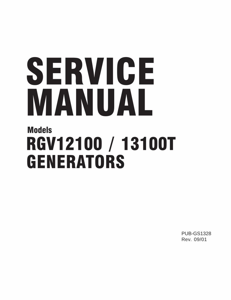
PUB-GS1328Rev. 09/01
���������
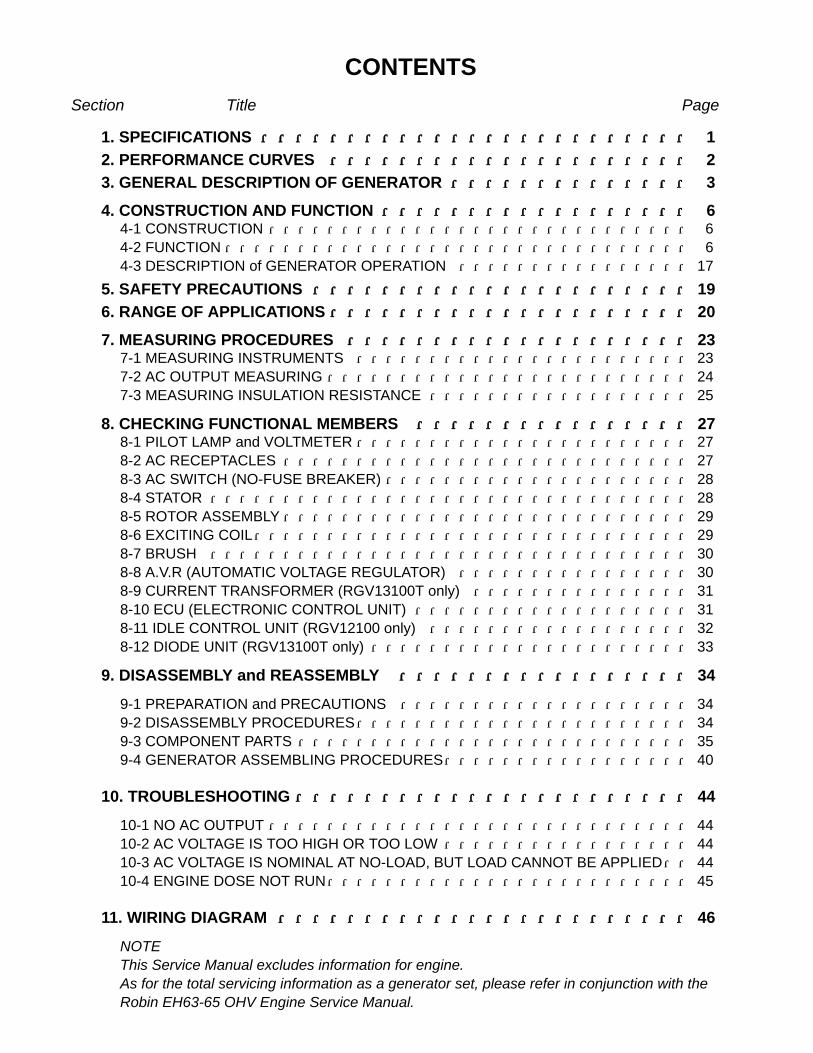
CONTENTSSection Title Page
1. SPECIFICATIONS ・・・・・・・・・・・・・・・・・・・・・・・・・・・・・・・・・・・・・・・・・・・・・・・・・・ 12. PERFORMANCE CURVES ・・・・・・・・・・・・・・・・・・・・・・・・・・・・・・・・・・・・・・・・・・ 23. GENERAL DESCRIPTION OF GENERATOR ・・・・・・・・・・・・・・・・・・・・・・・・・・・・ 3
4. CONSTRUCTION AND FUNCTION ・・・・・・・・・・・・・・・・・・・・・・・・・・・・・・・・・・・・ 64-1 CONSTRUCTION ・・・・・・・・・・・・・・・・・・・・・・・・・・・・・ 64-2 FUNCTION ・・・・・・・・・・・・・・・・・・・・・・・・・・・・・・・・ 64-3 DESCRIPTION of GENERATOR OPERATION ・・・・・・・・・・・・・・・・ 17
5. SAFETY PRECAUTIONS ・・・・・・・・・・・・・・・・・・・・・・・・・・・・・・・・・・・・・・・・・・・・ 196. RANGE OF APPLICATIONS ・・・・・・・・・・・・・・・・・・・・・・・・・・・・・・・・・・・・・・・・・・ 20
7. MEASURING PROCEDURES ・・・・・・・・・・・・・・・・・・・・・・・・・・・・・・・・・・・・・・・・ 237-1 MEASURING INSTRUMENTS ・・・・・・・・・・・・・・・・・・・・・・・ 237-2 AC OUTPUT MEASURING ・・・・・・・・・・・・・・・・・・・・・・・・・ 247-3 MEASURING INSULATION RESISTANCE ・・・・・・・・・・・・・・・・・・ 25
8. CHECKING FUNCTIONAL MEMBERS ・・・・・・・・・・・・・・・・・・・・・・・・・・・・・・・・ 278-1 PILOT LAMP and VOLTMETER・・・・・・・・・・・・・・・・・・・・・・・ 278-2 AC RECEPTACLES ・・・・・・・・・・・・・・・・・・・・・・・・・・・・ 278-3 AC SWITCH (NO-FUSE BREAKER) ・・・・・・・・・・・・・・・・・・・・・ 288-4 STATOR ・・・・・・・・・・・・・・・・・・・・・・・・・・・・・・・・・ 288-5 ROTOR ASSEMBLY・・・・・・・・・・・・・・・・・・・・・・・・・・・・ 298-6 EXCITING COIL・・・・・・・・・・・・・・・・・・・・・・・・・・・・・・ 298-7 BRUSH ・・・・・・・・・・・・・・・・・・・・・・・・・・・・・・・・・ 308-8 A.V.R (AUTOMATIC VOLTAGE REGULATOR) ・・・・・・・・・・・・・・・・ 308-9 CURRENT TRANSFORMER (RGV13100T only) ・・・・・・・・・・・・・・・ 318-10 ECU (ELECTRONIC CONTROL UNIT) ・・・・・・・・・・・・・・・・・・・ 318-11 IDLE CONTROL UNIT (RGV12100 only) ・・・・・・・・・・・・・・・・・・ 328-12 DIODE UNIT (RGV13100T only) ・・・・・・・・・・・・・・・・・・・・・・ 33
9. DISASSEMBLY and REASSEMBLY ・・・・・・・・・・・・・・・・・・・・・・・・・・・・・・・・・・ 34
9-1 PREPARATION and PRECAUTIONS ・・・・・・・・・・・・・・・・・・・・ 349-2 DISASSEMBLY PROCEDURES・・・・・・・・・・・・・・・・・・・・・・・ 349-3 COMPONENT PARTS ・・・・・・・・・・・・・・・・・・・・・・・・・・・ 359-4 GENERATOR ASSEMBLING PROCEDURES・・・・・・・・・・・・・・・・・ 40
10. TROUBLESHOOTING ・・・・・・・・・・・・・・・・・・・・・・・・・・・・・・・・・・・・・・・・・・・・・・ 44
10-1 NO AC OUTPUT ・・・・・・・・・・・・・・・・・・・・・・・・・・・・・ 4410-2 AC VOLTAGE IS TOO HIGH OR TOO LOW ・・・・・・・・・・・・・・・・・ 4410-3 AC VOLTAGE IS NOMINAL AT NO-LOAD, BUT LOAD CANNOT BE APPLIED・・ 4410-4 ENGINE DOSE NOT RUN・・・・・・・・・・・・・・・・・・・・・・・・・ 45
11. WIRING DIAGRAM ・・・・・・・・・・・・・・・・・・・・・・・・・・・・・・・・・・・・・・・・・・・・・・・・ 46
NOTEThis Service Manual excludes information for engine.As for the total servicing information as a generator set, please refer in conjunction with theRobin EH63-65 OHV Engine Service Manual.

-- 04--
-- 1--
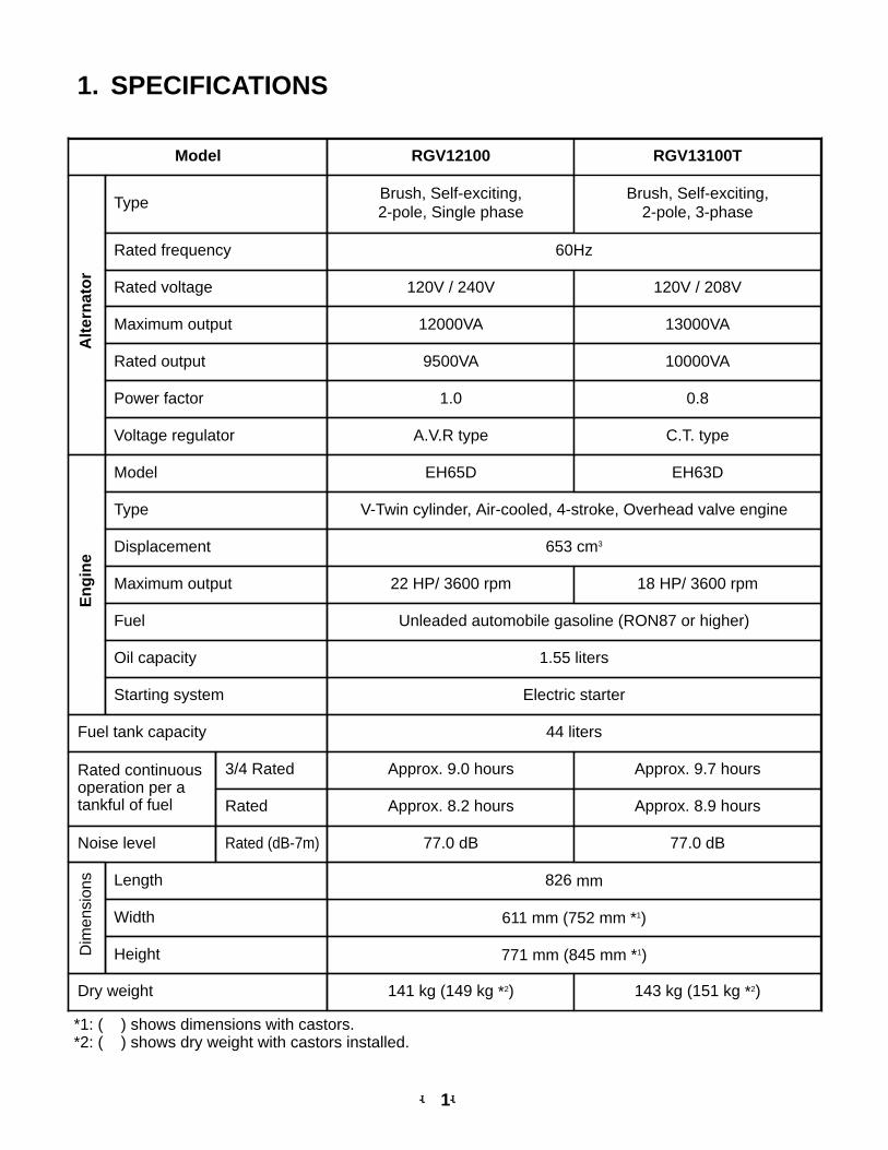
1. SPECIFICATIONS
Model RGV12100
Alt
ern
ato
r
Type
Rated voltage
Brush, Self-exciting, 2-pole, Single phase
611 mm (752 mm *1)
Rated frequency 60Hz
771 mm (845 mm *1)
120V / 240V
Maximum output 12000VA
Rated output 9500VA
Length
Power factor 1.0
Width
Voltage regulator
Height
A.V.R type
En
gin
e
Model EH65D
Type V-Twin cylinder, Air-cooled, 4-stroke, Overhead valve engine
Displacement 653 cm3
Maximum output 22 HP/ 3600 rpm
Fuel Unleaded automobile gasoline (RON87 or higher)
Oil capacity 1.55 liters
Starting system Electric starter
Fuel tank capacity 44 liters
Rated continuousoperation per atankful of fuel
3/4 Rated Approx. 9.0 hours
Rated Approx. 8.2 hours
Noise level Rated (dB-7m) 77.0 dB
Dim
ensi
ons 826 mm
Dry weight 141 kg (149 kg *2)
RGV13100T
120V / 208V
13000VA
10000VA
0.8
Approx. 9.7 hours
Approx. 8.9 hours
77.0 dB
18 HP/ 3600 rpm
*1: ( ) shows dimensions with castors.*2: ( ) shows dry weight with castors installed.
C.T. type
EH63D
143 kg (151 kg *2)
Brush, Self-exciting, 2-pole, 3-phase
-- 2--
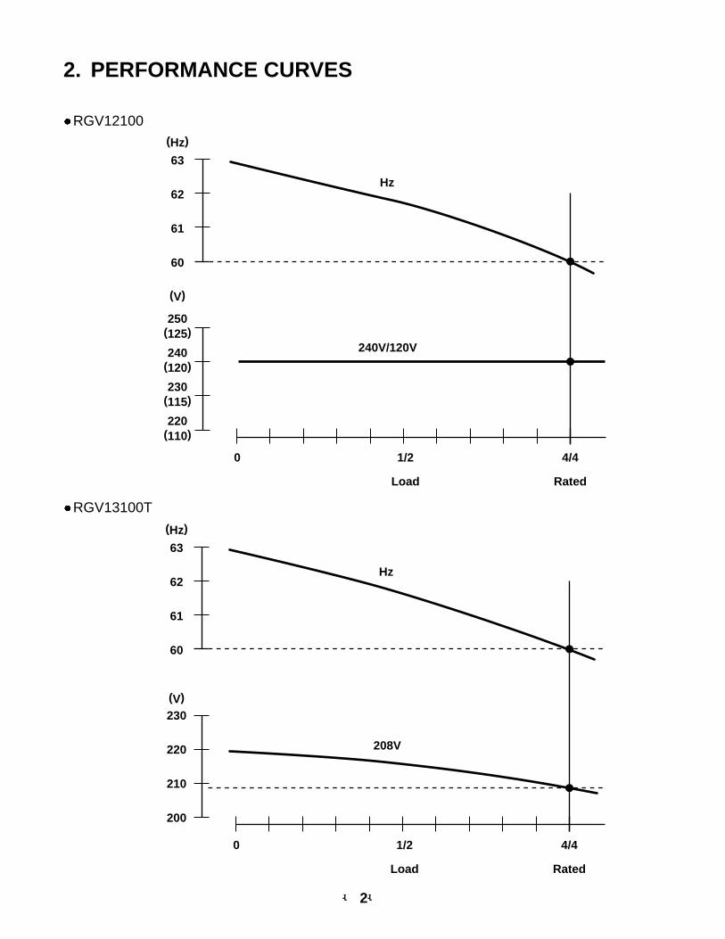
2. PERFORMANCE CURVES
Hz
(Hz)
(V)
(125)
63
250
(120)240
(115)230
(110)220
62
61
60
0 1/2 4/4
Load Rated
240V/120V
RGV12100
RGV13100T
Hz
(Hz)
(V)
63
230
220
210
200
62
61
60
0 1/2 4/4
Load Rated
208V
-- 3--
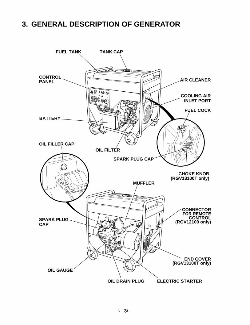
3. GENERAL DESCRIPTION OF GENERATOR
SPARK PLUG CAP
FUEL COCK
BATTERY
TANK CAP
SPARK PLUGCAP
OIL FILLER CAP
MUFFLER
CONNECTORFOR REMOTE
CONTROL(RGV12100 only)
END COVER(RGV13100T only)
FUEL TANK
CONTROLPANEL AIR CLEANER
COOLING AIRINLET PORT
OIL FILTER
CHOKE KNOB(RGV13100T only)
OIL GAUGE
ELECTRIC STARTEROIL DRAIN PLUG
-- 4--
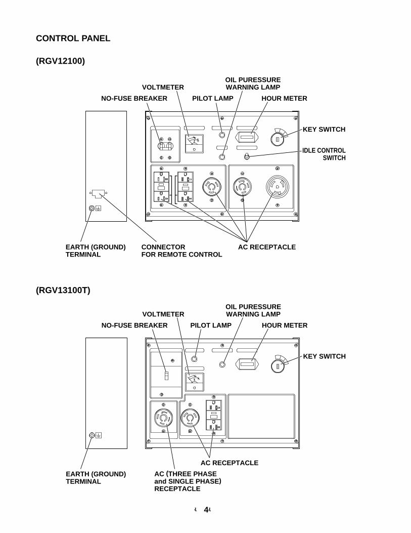
CONTROL PANEL
(RGV12100)
KEY SWITCH
OIL PURESSUREWARNING LAMP
0
240
110
120 220
IDLE CONTROLSWITCH
VOLTMETER
PILOT LAMP HOUR METERNO-FUSE BREAKER
AC RECEPTACLEEARTH (GROUND)TERMINAL
CONNECTORFOR REMOTE CONTROL
(RGV13100T)
KEY SWITCH
OIL PURESSUREWARNING LAMP
0
240
110
120 220
VOLTMETER
PILOT LAMP HOUR METERNO-FUSE BREAKER
AC RECEPTACLE
AC (THREE PHASEand SINGLE PHASE)RECEPTACLE
EARTH (GROUND)TERMINAL
SERIAL NUMBERstamped label
SERIAL NUMBERstamped label
-- 5--
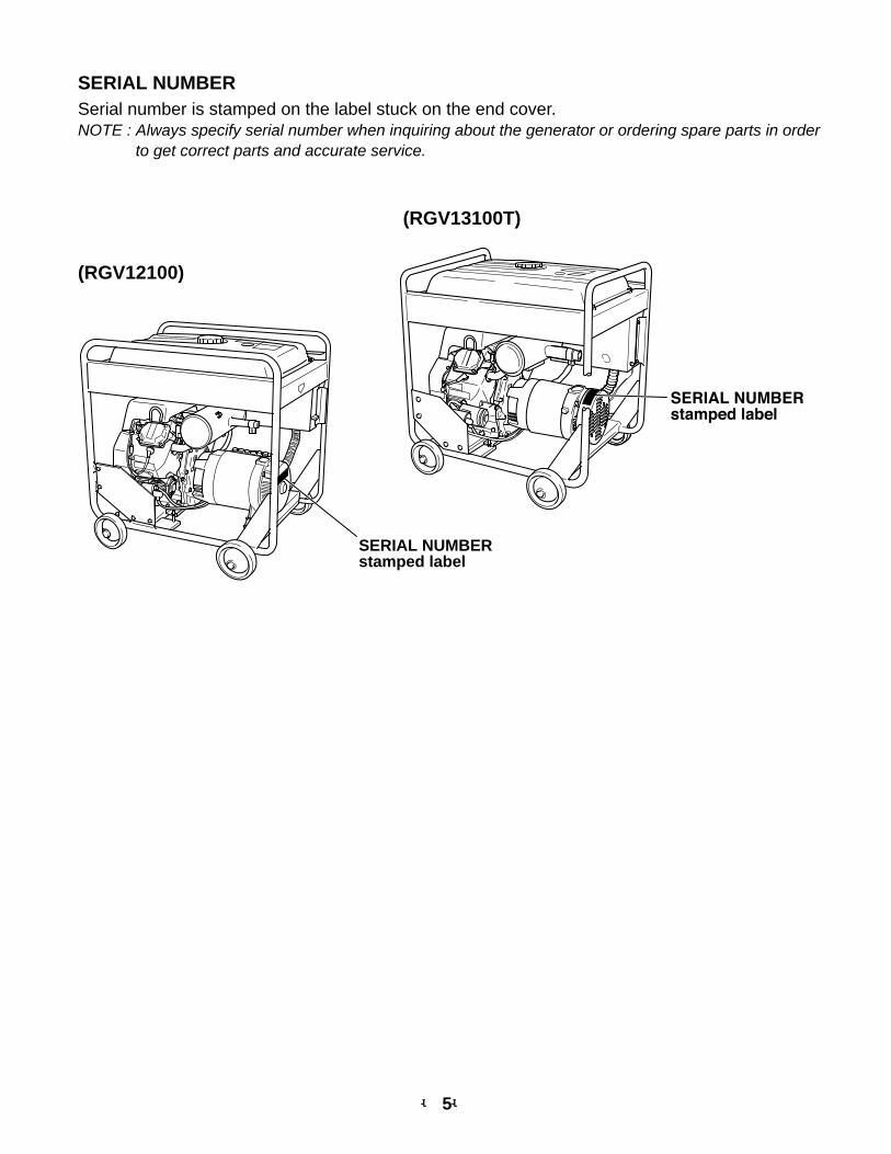
SERIAL NUMBERSerial number is stamped on the label stuck on the end cover.NOTE : Always specify serial number when inquiring about the generator or ordering spare parts in order
to get correct parts and accurate service.
(RGV13100T)
(RGV12100)
-- 6--
4. CONSTRUCTION AND FUNCTION
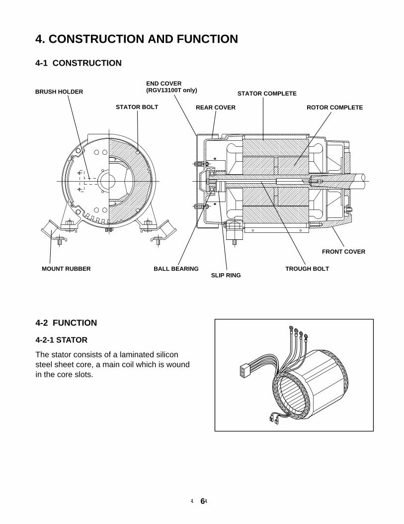
4-1 CONSTRUCTION
MOUNT RUBBER BALL BEARING TROUGH BOLT
FRONT COVER
REAR COVER ROTOR COMPLETE
STATOR COMPLETE
STATOR BOLT
END COVER(RGV13100T only)BRUSH HOLDER
SLIP RING
4-2 FUNCTION
4-2-1 STATOR
The stator consists of a laminated siliconsteel sheet core, a main coil which is woundin the core slots.
-- 7--
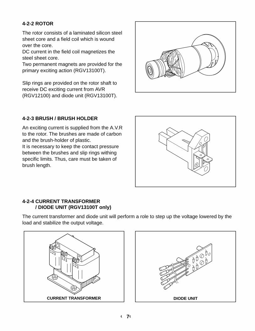
4-2-2 ROTOR
The rotor consists of a laminated silicon steelsheet core and a field coil which is woundover the core.DC current in the field coil magnetizes thesteel sheet core. Two permanent magnets are provided for theprimary exciting action (RGV13100T).
Slip rings are provided on the rotor shaft toreceive DC exciting current from AVR(RGV12100) and diode unit (RGV13100T).
4-2-3 BRUSH / BRUSH HOLDER
An exciting current is supplied from the A.V.Rto the rotor. The brushes are made of carbonand the brush-holder of plastic. It is necessary to keep the contact pressurebetween the brushes and slip rings withingspecific limits. Thus, care must be taken ofbrush length.
4-2-4 CURRENT TRANSFORMER/ DIODE UNIT (RGV13100T only)
The current transformer and diode unit will perform a role to step up the voltage lowered by theload and stabilize the output voltage.
1 2 3
1 2 3
1 2 3
CURRENT TRANSFORMER DIODE UNIT
-- 8--
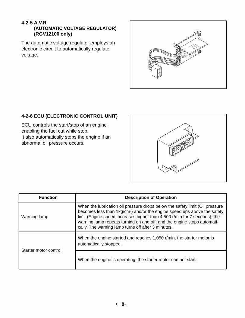
4-2-5 A.V.R (AUTOMATIC VOLTAGE REGULATOR)(RGV12100 only)
The automatic voltage regulator employs anelectronic circuit to automatically regulatevoltage.
4-2-6 ECU (ELECTRONIC CONTROL UNIT)
ECU controls the start/stop of an engineenabling the fuel cut while stop.It also automatically stops the engine if anabnormal oil pressure occurs.
Function Description of Operation
Warning lamp
When the lubrication oil pressure drops below the safety limit (Oil pressurebecomes less than 1kg/cm2) and/or the engine speed ups above the safetylimit (Engine speed increases higher than 4,500 r/min for 7 seconds), thewarning lamp repeats turning on and off, and the engine stops automati-cally. The warning lamp turns off after 3 minutes.
Starter motor control
When the engine started and reaches 1,050 r/min, the starter motor isautomatically stopped.
When the engine is operating, the starter motor can not start.
-- 9--
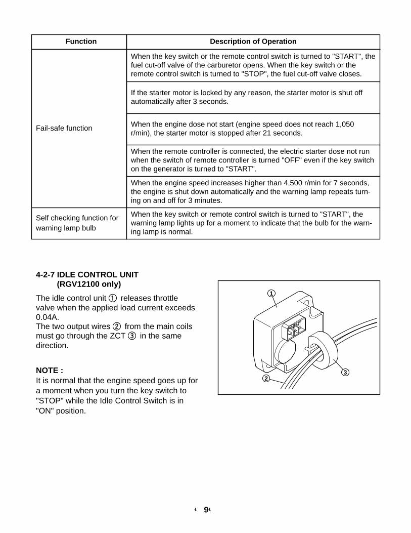
4-2-7 IDLE CONTROL UNIT (RGV12100 only)
The idle control unit 11 releases throttlevalve when the applied load current exceeds0.04A.The two output wires 22 from the main coilsmust go through the ZCT 33 in the samedirection.
NOTE :It is normal that the engine speed goes up fora moment when you turn the key switch to"STOP" while the Idle Control Switch is in"ON" position.
1
23
Function Description of Operation
Fail-safe function
When the key switch or the remote control switch is turned to "START", thefuel cut-off valve of the carburetor opens. When the key switch or theremote control switch is turned to "STOP", the fuel cut-off valve closes.
If the starter motor is locked by any reason, the starter motor is shut offautomatically after 3 seconds.
When the engine dose not start (engine speed does not reach 1,050r/min), the starter motor is stopped after 21 seconds.
When the remote controller is connected, the electric starter dose not runwhen the switch of remote controller is turned "OFF" even if the key switchon the generator is turned to "START".
When the engine speed increases higher than 4,500 r/min for 7 seconds,the engine is shut down automatically and the warning lamp repeats turn-ing on and off for 3 minutes.
Self checking function forwarning lamp bulb
When the key switch or remote control switch is turned to "START", thewarning lamp lights up for a moment to indicate that the bulb for the warn-ing lamp is normal.
-- 10--
Model Specification No-fuse Breaker Object of Protection
RGV12100 60Hz-120V/240V 39A Total output amperage
RGV13100T 60Hz-120V/208V 24A Total output amperage
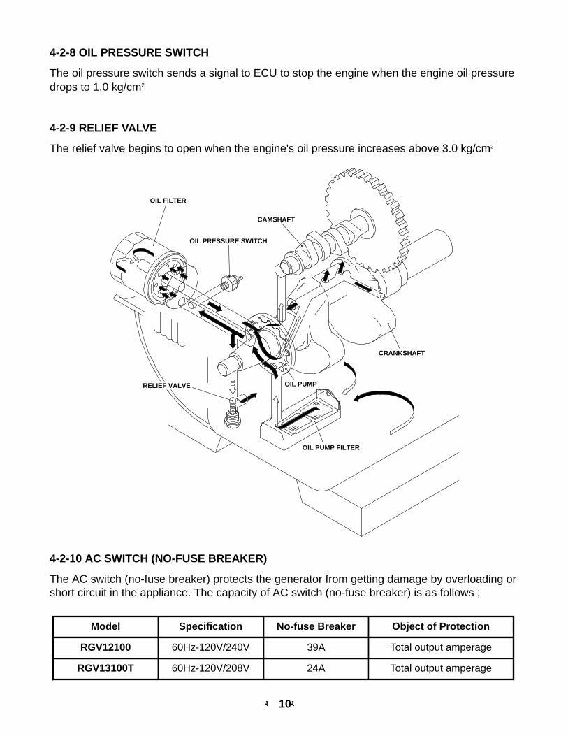
4-2-8 OIL PRESSURE SWITCH
The oil pressure switch sends a signal to ECU to stop the engine when the engine oil pressuredrops to 1.0 kg/cm2
4-2-9 RELIEF VALVE
The relief valve begins to open when the engine's oil pressure increases above 3.0 kg/cm2
4-2-10 AC SWITCH (NO-FUSE BREAKER)
The AC switch (no-fuse breaker) protects the generator from getting damage by overloading orshort circuit in the appliance. The capacity of AC switch (no-fuse breaker) is as follows ;
OIL PUMP
OIL PUMP FILTER
CRANKSHAFT
OIL FILTER
RELIEF VALVE
CAMSHAFT
OIL PRESSURE SWITCH
-- 11--
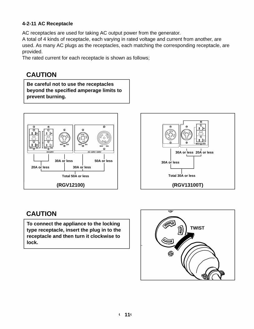
4-2-11 AC Receptacle
AC receptacles are used for taking AC output power from the generator. A total of 4 kinds of receptacle, each varying in rated voltage and current from another, areused. As many AC plugs as the receptacles, each matching the corresponding receptacle, areprovided.The rated current for each receptacle is shown as follows;
Be careful not to use the receptaclesbeyond the specified amperage limits toprevent burning.
CAUTION
CAUTIONTo connect the appliance to the lockingtype receptacle, insert the plug in to thereceptacle and then turn it clockwise tolock.
TWIST
Total 50A or less
20A or less
30A or less 50A or less
30A or less
AC120V
MAX 20A MAX 20A
MAX 30A MAX 30AMAX 50A
AC 120V / 240V
(RGV12100)
Total 30A or less
30A or less
20A or less30A or less
MAX 20A
(RGV13100T)
-- 12--
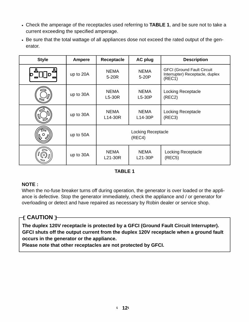
■ Check the amperage of the receptacles used referring to TABLE 1, and be sure not to take acurrent exceeding the specified amperage.
■ Be sure that the total wattage of all appliances dose not exceed the rated output of the gen-erator.
TABLE 1
NOTE :When the no-fuse breaker turns off during operation, the generator is over loaded or the appli-ance is defective. Stop the generator immediately, check the appliance and / or generator foroverloading or detect and have repaired as necessary by Robin dealer or service shop.
The duplex 120V receptacle is protected by a GFCI (Ground Fault Circuit Interrupter).GFCI shuts off the output current from the duplex 120V receptacle when a ground faultoccurs in the generator or the appliance.Please note that other receptacles are not protected by GFCI.
[CAUTION]
up to 30A
up to 30A
up to 20ANEMA5-20R
NEMAL5-30R
NEMAL14-30R
NEMA5-20P
NEMAL5-30P
NEMAL14-30P
GFCI (Ground Fault CircuitInterrupter) Receptacle, duplex(REC1)
Locking Receptacle(REC2)
Locking Receptacle(REC3)
Style Ampere Receptacle AC plug Description
up to 30ANEMA
L21-30RNEMA
L21-30P
up to 50ALocking Receptacle(REC4)
Locking Receptacle(REC5)
-- 13--
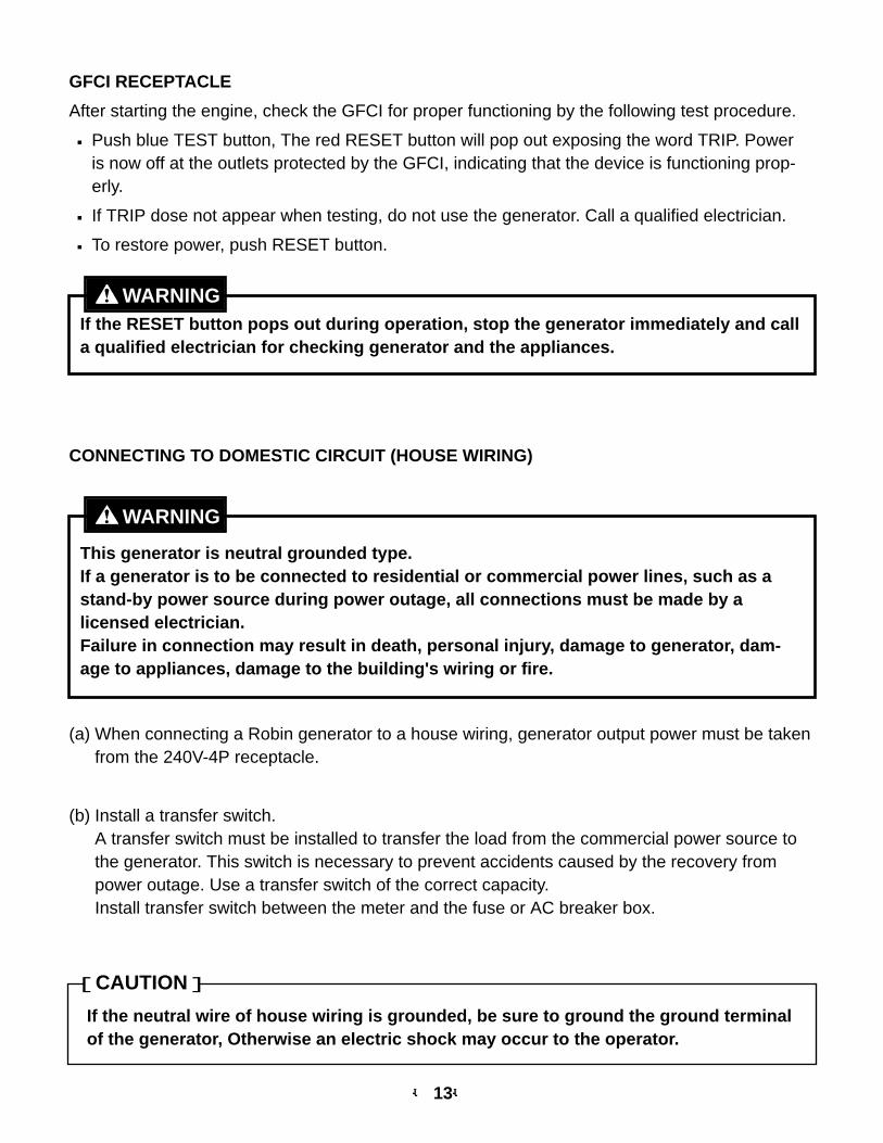
GFCI RECEPTACLE
After starting the engine, check the GFCI for proper functioning by the following test procedure.
■ Push blue TEST button, The red RESET button will pop out exposing the word TRIP. Poweris now off at the outlets protected by the GFCI, indicating that the device is functioning prop-erly.
■ If TRIP dose not appear when testing, do not use the generator. Call a qualified electrician.
■ To restore power, push RESET button.
If the RESET button pops out during operation, stop the generator immediately and calla qualified electrician for checking generator and the appliances.
WARNING
CONNECTING TO DOMESTIC CIRCUIT (HOUSE WIRING)
This generator is neutral grounded type.If a generator is to be connected to residential or commercial power lines, such as astand-by power source during power outage, all connections must be made by alicensed electrician.Failure in connection may result in death, personal injury, damage to generator, dam-age to appliances, damage to the building's wiring or fire.
WARNING
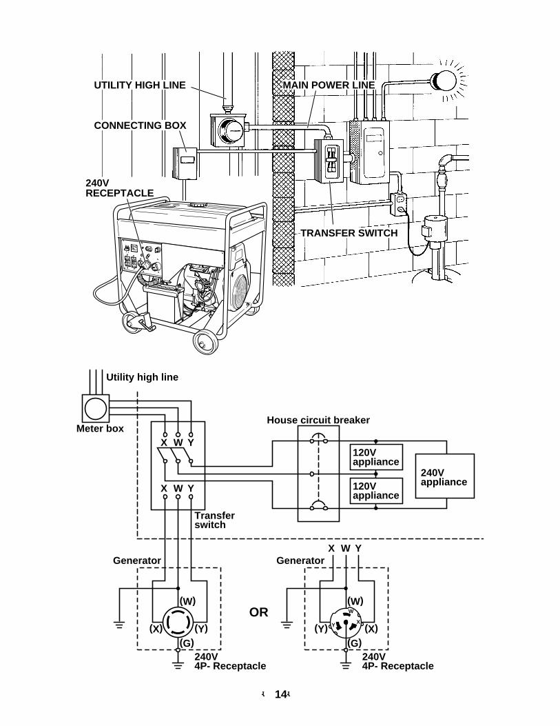
(a) When connecting a Robin generator to a house wiring, generator output power must be takenfrom the 240V-4P receptacle.
(b) Install a transfer switch.A transfer switch must be installed to transfer the load from the commercial power source tothe generator. This switch is necessary to prevent accidents caused by the recovery frompower outage. Use a transfer switch of the correct capacity.Install transfer switch between the meter and the fuse or AC breaker box.
If the neutral wire of house wiring is grounded, be sure to ground the ground terminalof the generator, Otherwise an electric shock may occur to the operator.
[CAUTION]
-- 14--
MAIN POWER LINE
TRANSFER SWITCH
UTILITY HIGH LINE
CONNECTING BOX
240VRECEPTACLE
Utility high line
Meter box
Generator
House circuit breaker
X W Y
X
(X) (Y)(G)
(W)
W Y
X W Y
Transferswitch
240V4P- Receptacle
120Vappliance
120Vappliance
240Vappliance
OR
Generator
(X)(Y)(G)
(W)
240V4P- Receptacle
W
XY
-- 15--
(c) Operating the generator.
■ Turn the house AC breaker off before starting the generator.
■ Start the generator and warm it up.
■ Turn the house AC breaker on.
Do not start the generator with electrical appliance (s) connected and with their switch-es on.
Otherwise the appliance (s) may be damaged by the surge voltage at starting.
[CAUTION]
4-2-12 3-PHASE APPLICATION (RGV13100T only)
Connection of Power Cables
■ Do not touch output terminals while the generator is running or the operator may suf-fer severe electric shock resulting in death.
■ Be sure to shut down the generator before connecting or changing connection ofpower cables to the generator.
WARNING
This generator has four output terminals of three phase, four wire system.
Connect power cables to the generator output terminals according to the type of application.
-- 16--
SINGLE-PHASE OUTPUT
W G
Y
X
Z
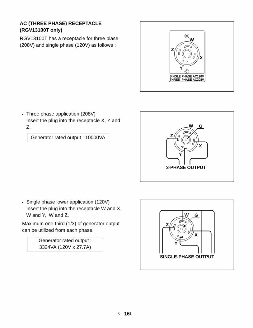
■ Three phase application (208V)Insert the plug into the receptacle X, Y andZ.
Generator rated output : 10000VA
AC (THREE PHASE) RECEPTACLE(RGV13100T only)
RGV13100T has a receptacle for three plase(208V) and single phase (120V) as follows :
■ Single phase lower application (120V)Insert the plug into the receptacle W and X,W and Y, W and Z.
Maximum one-third (1/3) of generator outputcan be utilized from each phase.
W G
Y
X
Z
3-PHASE OUTPUT
Generator rated output : 3324VA (120V x 27.7A)
SINGLE PHASE AC120VTHREE PHASE AC208V
W
Y
X
Z
-- 17--
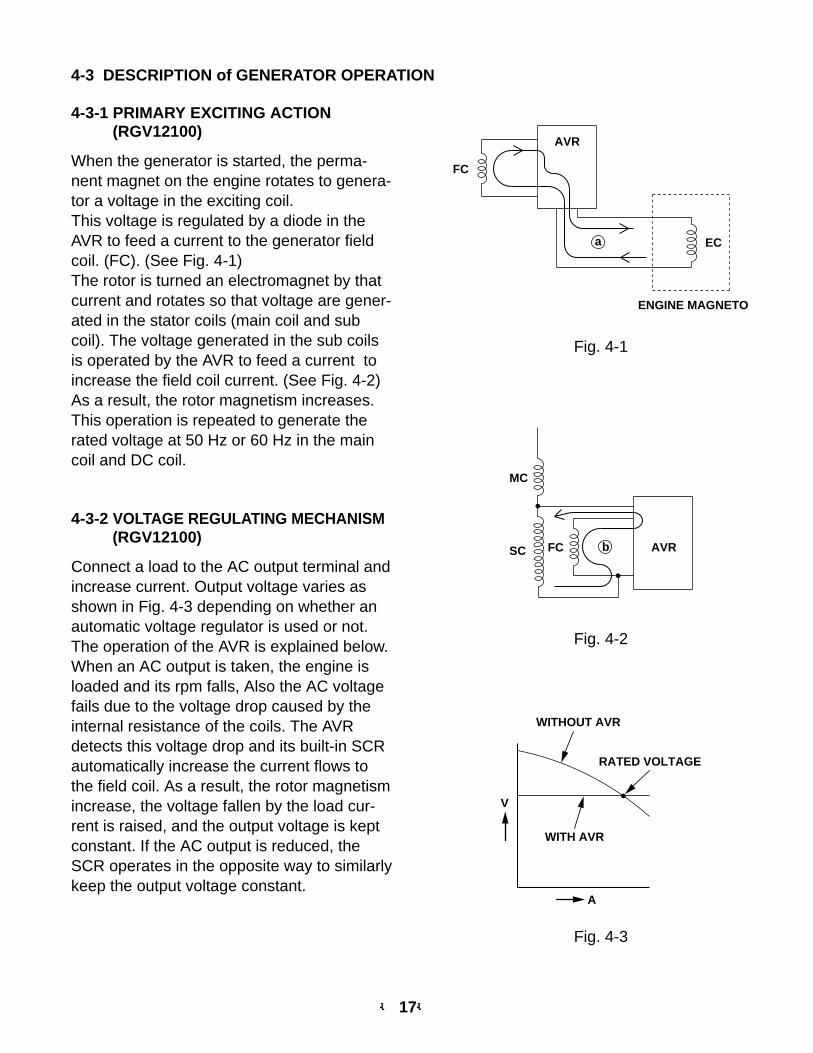
4-3 DESCRIPTION of GENERATOR OPERATION
4-3-1 PRIMARY EXCITING ACTION(RGV12100)
When the generator is started, the perma-nent magnet on the engine rotates to genera-tor a voltage in the exciting coil.This voltage is regulated by a diode in theAVR to feed a current to the generator fieldcoil. (FC). (See Fig. 4-1)The rotor is turned an electromagnet by thatcurrent and rotates so that voltage are gener-ated in the stator coils (main coil and subcoil). The voltage generated in the sub coilsis operated by the AVR to feed a current toincrease the field coil current. (See Fig. 4-2)As a result, the rotor magnetism increases.This operation is repeated to generate therated voltage at 50 Hz or 60 Hz in the maincoil and DC coil.
4-3-2 VOLTAGE REGULATING MECHANISM(RGV12100)
Connect a load to the AC output terminal andincrease current. Output voltage varies asshown in Fig. 4-3 depending on whether anautomatic voltage regulator is used or not.The operation of the AVR is explained below.When an AC output is taken, the engine isloaded and its rpm falls, Also the AC voltagefails due to the voltage drop caused by theinternal resistance of the coils. The AVRdetects this voltage drop and its built-in SCRautomatically increase the current flows tothe field coil. As a result, the rotor magnetismincrease, the voltage fallen by the load cur-rent is raised, and the output voltage is keptconstant. If the AC output is reduced, theSCR operates in the opposite way to similarlykeep the output voltage constant.
FC
ECa
AVR
ENGINE MAGNETO
AVR
MC
FCSC b
Fig. 4-1
Fig. 4-2
WITH AVR
A
RATED VOLTAGE
WITHOUT AVR
V
Fig. 4-3
-- 18--
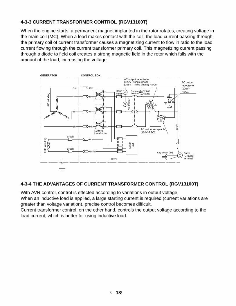
4-3-4 THE ADVANTAGES OF CURRENT TRANSFORMER CONTROL (RGV13100T)
With AVR control, control is effected according to variations in output voltage.When an inductive load is applied, a large starting current is required (current variations aregreater than voltage variation), precise control becomes difficult.Current transformer control, on the other hand, controls the output voltage according to theload current, which is better for using inductive load.
4-3-3 CURRENT TRANSFORMER CONTROL (RGV13100T)
When the engine starts, a permanent magnet implanted in the rotor rotates, creating voltage inthe main coil (MC). When a load makes contact with the coil, the load current passing throughthe primary coil of current transformer causes a magnetizing current to flow in ratio to the loadcurrent flowing through the current transformer primary coil. This magnetizing current passingthrough a diode to field coil creates a strong magnetic field in the rotor which falls with theamount of the load, increasing the voltage.
R
Grn
W
Blk
R
W
Blk
Brn
Grn/W
Y
R
Y
W
Y
Blk
GENERATOR CONTROL BOX
V
PLHr
AC
Win
ding
Fel
d W
indi
ng
Brush
Brush Dio
deun
it
AC outputreceptacle(120V)REC1
AC output receptacle(120V : Single phase)(208V : Three phase) REC5
AC output receptacle(120V)REC2
WX
W
W
H
G
G
G
Y
Z
Grn/Y
Grn
/Y
Vol
tmet
er
No-fusebreaker
Earth(Ground)terminal
Pilotlamp
Hourmeter
Grn
Key switch (-M)
Currenttransformer
1
2 3
1
2 3
1
2 3
-- 19--
5. SAFETY PRECAUTIONS
1. Use extreme caution near fuel. A constant danger of explosion or fire exists.Do not fill the fuel tank while the engine is running. Do not smoke or use open flame near thefuel tank. Be careful not to spill fuel when refueling. If spilt, wipe it and let dry before startingthe engine.
2. Do not place inflammable materials near the generator.Be careful not to put fuel, matches, gunpowder, oily cloth, straw, and any other inflammablesnear the generator.
3. Do not operate the generator in a room, cave or tunnel. Always operate in a well-venti-lated area.Otherwise the engine may overheat and also, the poisonous carbon monoxide contained inthe exhaust gases will endanger human lives. Keep the generator at least 1 m (3 feet) awayfrom structures or facilities during use.
4. Operate the generator on a level surface.If the generator is tilted or moved during use, there is a danger of fuel spillage and a chancethat the generator may tip over.
5. Do not operate with wet hands or in the rain.Severe electric shock may occur. If the generator is wet by rain or snow, wipe it and thor-oughly dry it before starting.Don't pour water over the generator directly nor wash it with water.If the generator is wet with water, the insulation's will be adversely affected and may causecurrent leakage and electric shock.
6. Do not connect the generator to the commercial power lines.This may cause a short-circuit or damage to the generator.
7. Be sure to check and remedy the cause of circuit breaker tripping before re-setting iton.
CAUTION : If the circuit breaker tripped off as a result of using an electrical appliance,the cause can be an overload or a short-circuit. In such a case, stop opera-tion immediately and carefully check the electrical appliance and AC plugsfor faulty wiring.
-- 20--
6. RANGE OF APPLICATIONS
Generally, the power rating of an electrical appliance indicates the amount of work that can bedone by it. The electric power required for operating an electrical appliance is not always equalto the output wattage of the appliance. The electrical appliances generally have a label show-ing their rated voltage, frequency, and power consumption(input wattage). The power con-sumption of an electrical appliance is the power necessary for using it. When using a generatorfor operating an electrical appliance, the power factor and starting wattage must be taken intoconsideration.In order to determine the right size generator, it is necessary to add the total wattage of allappliances to be connected to the unit.Refer to the followings to calculate the power consumption of each appliance or equipment byits type.
(1) Incandescent lamp, heater, etc. with a power factor of 1.0 Total power consumption must be equal to or less than the rated output of generator.Example : A rated 3000 W generator can turn thirty 100W incandescent lamps on.
(2) Fluorescent lamps, mercury lamps, etc. with a smaller power factorSelect a generator with a rated output equivalent to 1.2 to 2 times of the power consump-tion of the load.Example : A 400W mercury lamp requires 600 W to 700 W power source to be turned on.
A rated 3000 W generator can power four or five 400 W mercury lamps.NOTE 1 : If a power factor correction capacitor is not applied to the mercury lamp or fluorescent
lamp, the more power shall be required to drive those lamps.A rated 3000W generator can drive one or two 400W mercury lamps without power fac-tor correction capacitors.
NOTE 2 : Nominal wattage of the fluorescent lamp generally indicates the output wattage of thelamp.Therefore, if the fluorescent lamp has no special indication as to the power consumption,efficiency should be taken into account as explained in item (5) on the following page.
(3) Motor driven tools and light electrical appliancesGenerally the starting wattage of motor driven tools and light electrical appliances are 1.2to 3 times lager than their running wattage.Example : A rated 250 W electric drill requires a 400 W generator to start it.
(4) Initially loaded motor driven appliances such as water pumps, compressors, etc.These appliances require large starting wattage which is 3 to 5 times of running wattage.Example : A rated 900 W compressor requires a 4500 W generator to drive it.
NOTE 1 : Motor-driven appliances require the aforementioned generator output only at the starting.Once their motors are started, the appliances consume about 1.2 to 2 times their ratedpower consumption so that the excess power generated by the generator can be used forother electrical appliances.
-- 21--
NOTE 2 : Motor-driven appliances mentioned in lets (3) and (4) vary in their required motor startingpower depending on the kind of motor and start-up load. If it is difficult to determine theoptimum generator capacity, select a generator with a larger capacity.
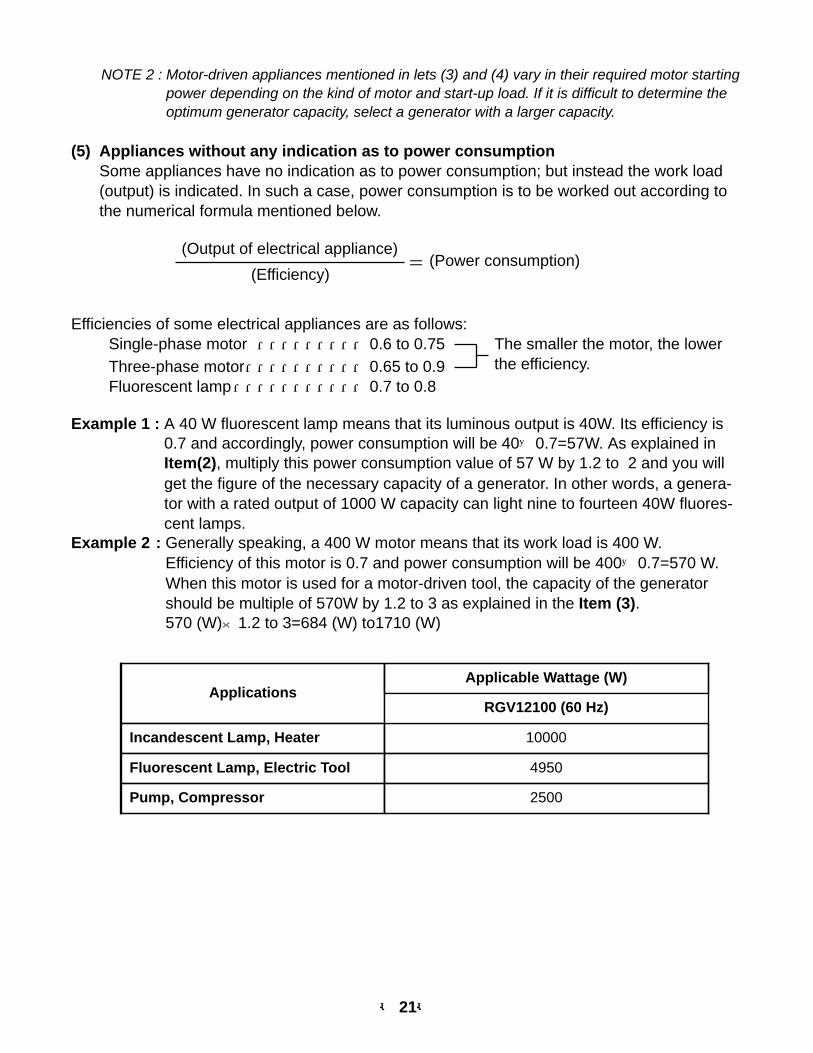
(5) Appliances without any indication as to power consumptionSome appliances have no indication as to power consumption; but instead the work load(output) is indicated. In such a case, power consumption is to be worked out according tothe numerical formula mentioned below.
(Output of electrical appliance)
(Efficiency)
Efficiencies of some electrical appliances are as follows:Single-phase motor ・・・・・・・・・0.6 to 0.75 The smaller the motor, the lower
the efficiency.Three-phase motor・・・・・・・・・・0.65 to 0.9Fluorescent lamp・・・・・・・・・・・0.7 to 0.8
Example 1 : A 40 W fluorescent lamp means that its luminous output is 40W. Its efficiency is0.7 and accordingly, power consumption will be 40÷0.7=57W. As explained inItem(2), multiply this power consumption value of 57 W by 1.2 to 2 and you willget the figure of the necessary capacity of a generator. In other words, a genera-tor with a rated output of 1000 W capacity can light nine to fourteen 40W fluores-cent lamps.
Example 2 : Generally speaking, a 400 W motor means that its work load is 400 W. Efficiency of this motor is 0.7 and power consumption will be 400÷0.7=570 W.When this motor is used for a motor-driven tool, the capacity of the generatorshould be multiple of 570W by 1.2 to 3 as explained in the Item (3).570 (W)×1.2 to 3=684 (W) to1710 (W)
= (Power consumption)
ApplicationsApplicable Wattage (W)
Incandescent Lamp, Heater 10000
Fluorescent Lamp, Electric Tool 4950
Pump, Compressor 2500
RGV12100 (60 Hz)
-- 22--
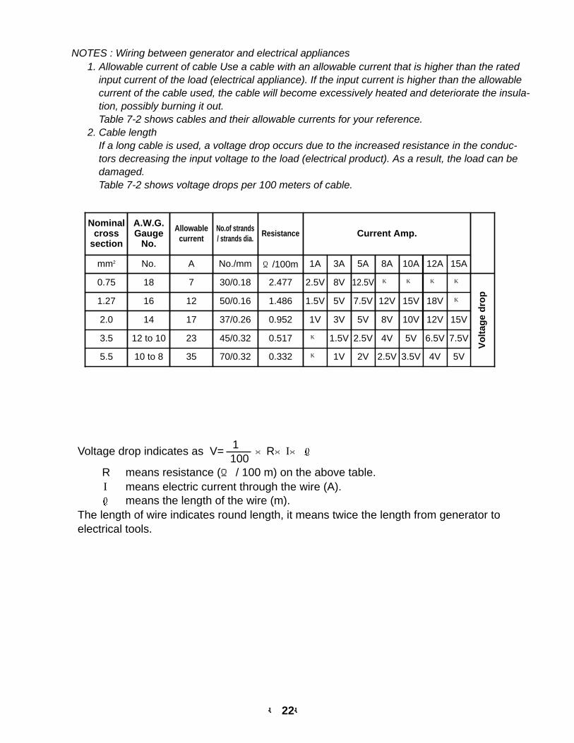
NOTES : Wiring between generator and electrical appliances1. Allowable current of cable Use a cable with an allowable current that is higher than the rated
input current of the load (electrical appliance). If the input current is higher than the allowablecurrent of the cable used, the cable will become excessively heated and deteriorate the insula-tion, possibly burning it out.Table 7-2 shows cables and their allowable currents for your reference.
2. Cable lengthIf a long cable is used, a voltage drop occurs due to the increased resistance in the conduc-tors decreasing the input voltage to the load (electrical product). As a result, the load can bedamaged.Table 7-2 shows voltage drops per 100 meters of cable.
1Voltage drop indicates as V=
100 ×R×I×
R means resistance (Ω / 100 m) on the above table.I means electric current through the wire (A).
means the length of the wire (m).The length of wire indicates round length, it means twice the length from generator toelectrical tools.
Nominalcross
section
A.W.G. Gauge
No.
Allowablecurrent
No.of strands/ strands dia.
Resistance Current Amp.
No./mm Ω/100mmm2 No. A 1A 3A 5A 8A 10A 12A 15A
0.75 18 7 30/0.18 2.477 2.5V 8V 12.5V ─ ─ ─ ─
Vo
ltag
e d
rop
1.27 16 12 50/0.16 1.486 1.5V 5V 7.5V 12V 15V 18V ─
2.0 14 17 37/0.26 0.952 1V 3V 5V 8V 10V 12V 15V
3.5 12 to 10 23 45/0.32 0.517 ─ 1.5V 2.5V 4V 5V 6.5V 7.5V
5.5 10 to 8 35 70/0.32 0.332 ─ 1V 2V 2.5V 3.5V 4V 5V
-- 23--
FOR AC
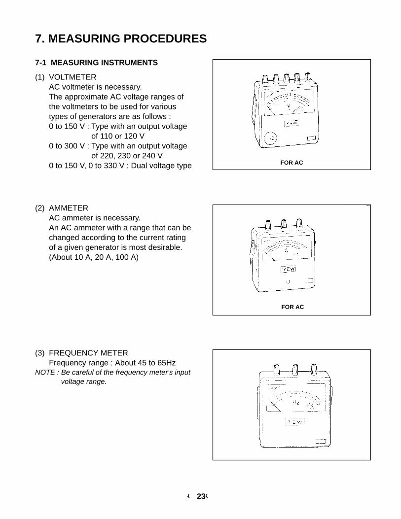
7. MEASURING PROCEDURES
(2) AMMETERAC ammeter is necessary. An AC ammeter with a range that can bechanged according to the current ratingof a given generator is most desirable.(About 10 A, 20 A, 100 A)
(3) FREQUENCY METERFrequency range : About 45 to 65Hz
NOTE : Be careful of the frequency meter's inputvoltage range.
7-1 MEASURING INSTRUMENTS
(1) VOLTMETERAC voltmeter is necessary. The approximate AC voltage ranges ofthe voltmeters to be used for varioustypes of generators are as follows :0 to 150 V : Type with an output voltage
of 110 or 120 V0 to 300 V : Type with an output voltage
of 220, 230 or 240 V0 to 150 V, 0 to 330 V : Dual voltage type
FOR AC
-- 24--
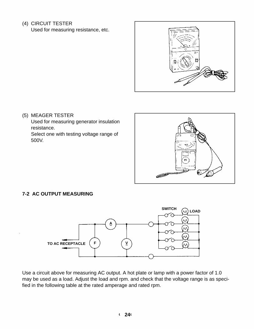
(4) CIRCUIT TESTERUsed for measuring resistance, etc.
(5) MEAGER TESTERUsed for measuring generator insulationresistance.Select one with testing voltage range of500V.
7-2 AC OUTPUT MEASURING
SWITCHLOAD
TO AC RECEPTACLE F
A~
V~
Use a circuit above for measuring AC output. A hot plate or lamp with a power factor of 1.0may be used as a load. Adjust the load and rpm. and check that the voltage range is as speci-fied in the following table at the rated amperage and rated rpm.
-- 25--
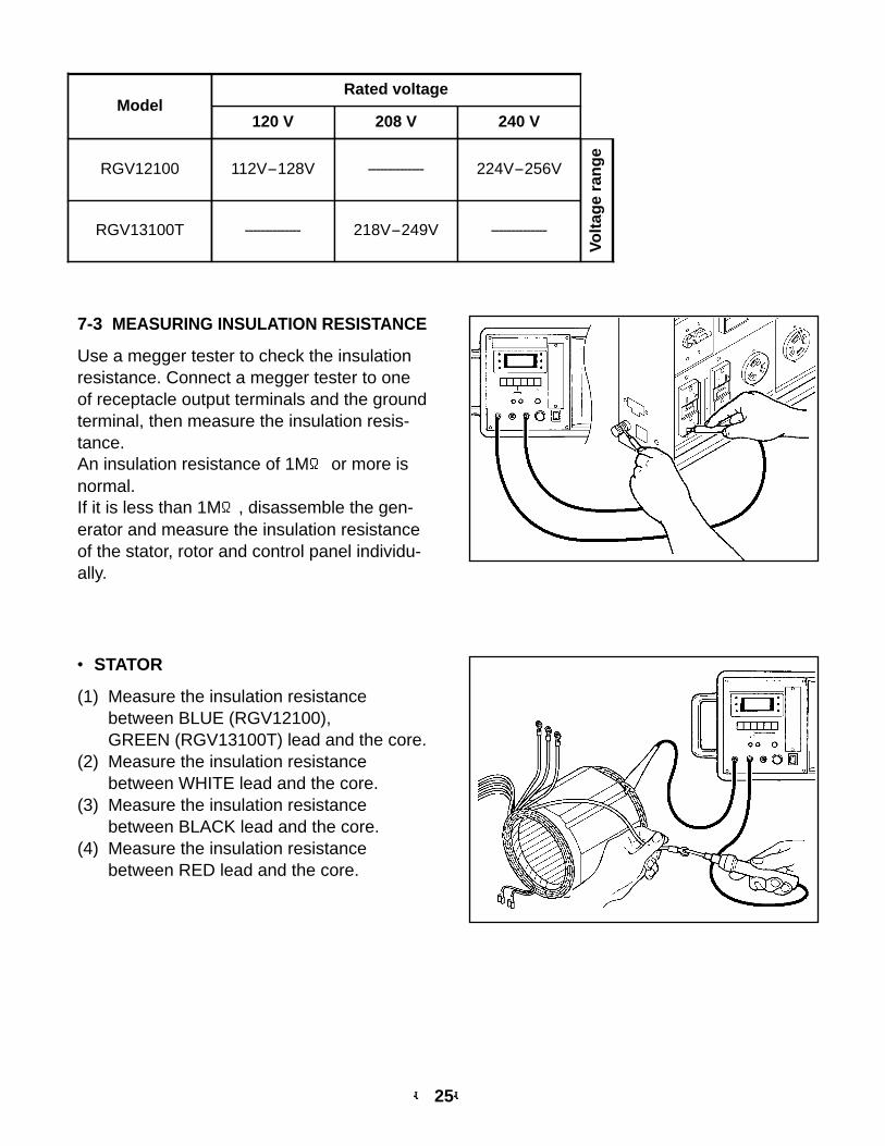
7-3 MEASURING INSULATION RESISTANCE
Use a megger tester to check the insulationresistance. Connect a megger tester to oneof receptacle output terminals and the groundterminal, then measure the insulation resis-tance.An insulation resistance of 1MΩ or more isnormal.If it is less than 1MΩ, disassemble the gen-erator and measure the insulation resistanceof the stator, rotor and control panel individu-ally.
● STATOR
(1) Measure the insulation resistancebetween BLUE (RGV12100), GREEN (RGV13100T) lead and the core.
(2) Measure the insulation resistancebetween WHITE lead and the core.
(3) Measure the insulation resistancebetween BLACK lead and the core.
(4) Measure the insulation resistancebetween RED lead and the core.
120 V 208 V 240 V
RGV12100 112V-128V -------------- 224V-256V
RGV13100T -------------- 218V-249V --------------
Volt
age
ran
ge
ModelRated voltage
-- 26--
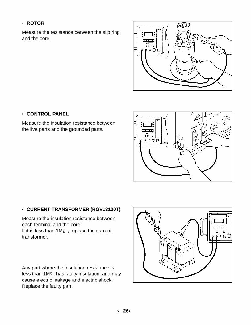
● ROTOR
Measure the resistance between the slip ringand the core.
● CONTROL PANEL
Measure the insulation resistance betweenthe live parts and the grounded parts.
● CURRENT TRANSFORMER (RGV13100T)
Measure the insulation resistance betweeneach terminal and the core.If it is less than 1MΩ, replace the currenttransformer.
Any part where the insulation resistance isless than 1MΩ has faulty insulation, and maycause electric leakage and electric shock.Replace the faulty part.
-- 27--
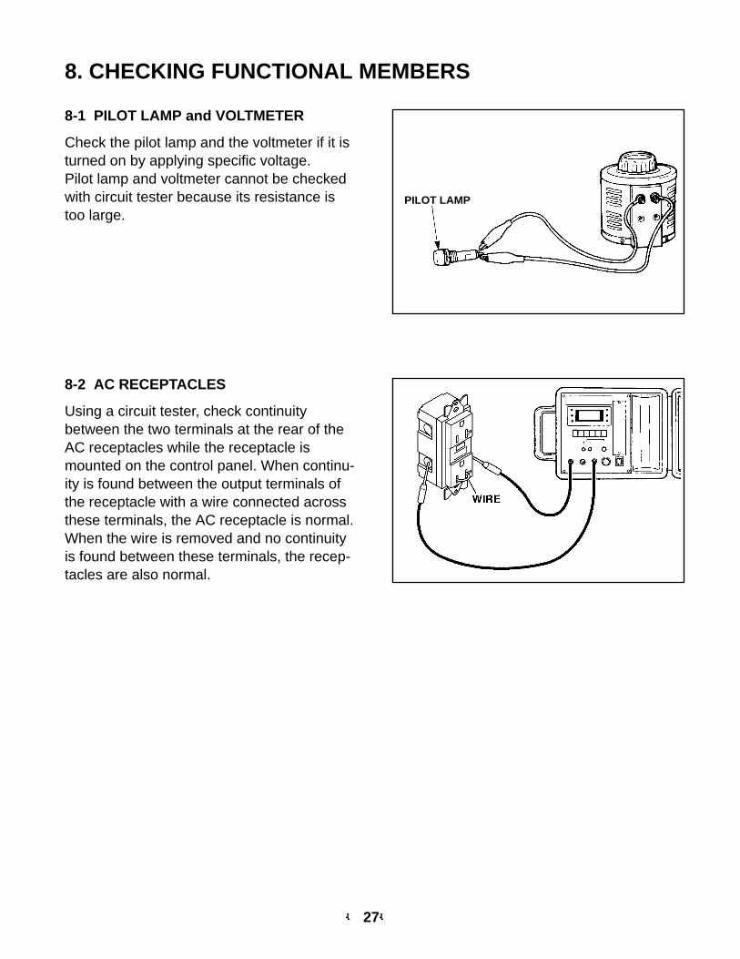
8. CHECKING FUNCTIONAL MEMBERS
PILOT LAMP
8-2 AC RECEPTACLES
Using a circuit tester, check continuitybetween the two terminals at the rear of theAC receptacles while the receptacle ismounted on the control panel. When continu-ity is found between the output terminals ofthe receptacle with a wire connected acrossthese terminals, the AC receptacle is normal.When the wire is removed and no continuityis found between these terminals, the recep-tacles are also normal.
8-1 PILOT LAMP and VOLTMETER
Check the pilot lamp and the voltmeter if it isturned on by applying specific voltage.Pilot lamp and voltmeter cannot be checkedwith circuit tester because its resistance istoo large.
-- 28--
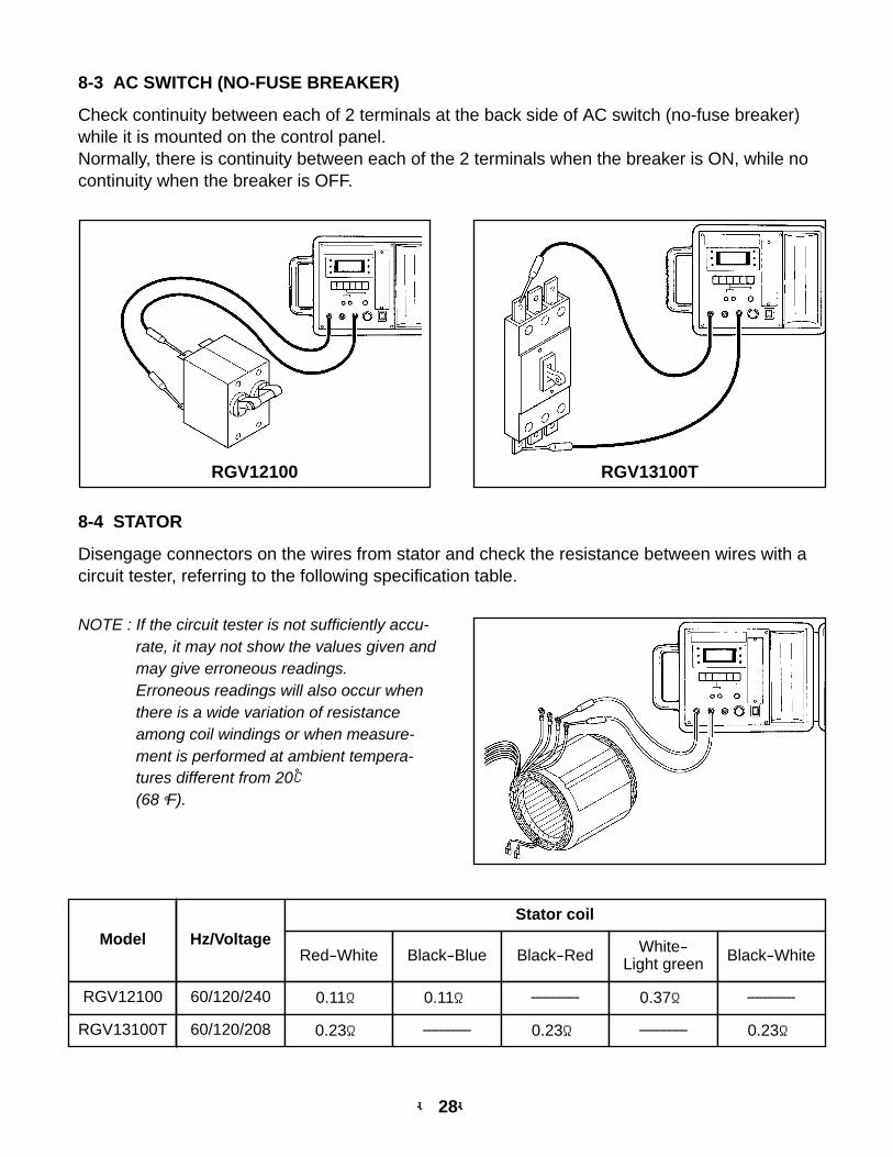
Model Hz/Voltage
Stator coil
Red-White Black-Blue Black-Red White-Light green Black-White
RGV12100 60/120/240 0.11Ω 0.11Ω ------------ 0.37Ω ------------
RGV13100T 60/120/208 0.23Ω ------------ 0.23Ω ------------ 0.23Ω
8-4 STATOR
Disengage connectors on the wires from stator and check the resistance between wires with acircuit tester, referring to the following specification table.
NOTE : If the circuit tester is not sufficiently accu-rate, it may not show the values given andmay give erroneous readings.Erroneous readings will also occur whenthere is a wide variation of resistanceamong coil windings or when measure-ment is performed at ambient tempera-tures different from 20℃(68°F).
8-3 AC SWITCH (NO-FUSE BREAKER)
Check continuity between each of 2 terminals at the back side of AC switch (no-fuse breaker)while it is mounted on the control panel.Normally, there is continuity between each of the 2 terminals when the breaker is ON, while nocontinuity when the breaker is OFF.
RGV13100TRGV12100
-- 29--
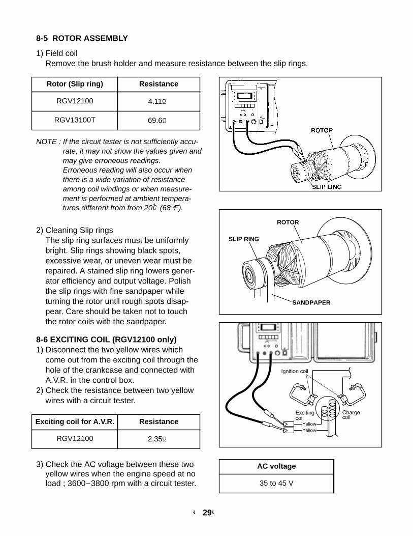
8-5 ROTOR ASSEMBLY
1) Field coilRemove the brush holder and measure resistance between the slip rings.
NOTE : If the circuit tester is not sufficiently accu-rate, it may not show the values given andmay give erroneous readings.Erroneous reading will also occur whenthere is a wide variation of resistanceamong coil windings or when measure-ment is performed at ambient tempera-tures different from from 20℃(68°F).
2) Cleaning Slip ringsThe slip ring surfaces must be uniformlybright. Slip rings showing black spots,excessive wear, or uneven wear must berepaired. A stained slip ring lowers gener-ator efficiency and output voltage. Polishthe slip rings with fine sandpaper whileturning the rotor until rough spots disap-pear. Care should be taken not to touchthe rotor coils with the sandpaper.
Rotor (Slip ring) Resistance
RGV12100 4.11Ω
RGV13100T 69.6Ω
SLIP RING
ROTOR
SANDPAPER
8-6 EXCITING COIL (RGV12100 only)1) Disconnect the two yellow wires which
come out from the exciting coil through thehole of the crankcase and connected withA.V.R. in the control box.
2) Check the resistance between two yellowwires with a circuit tester.
Ignition coil
Chargecoil
Excitingcoil
Yellow
Yellow
Exciting coil for A.V.R. Resistance
RGV12100 2.35Ω
3) Check the AC voltage between these twoyellow wires when the engine speed at noload ; 3600-3800 rpm with a circuit tester.
AC voltage
35 to 45 V
-- 30--
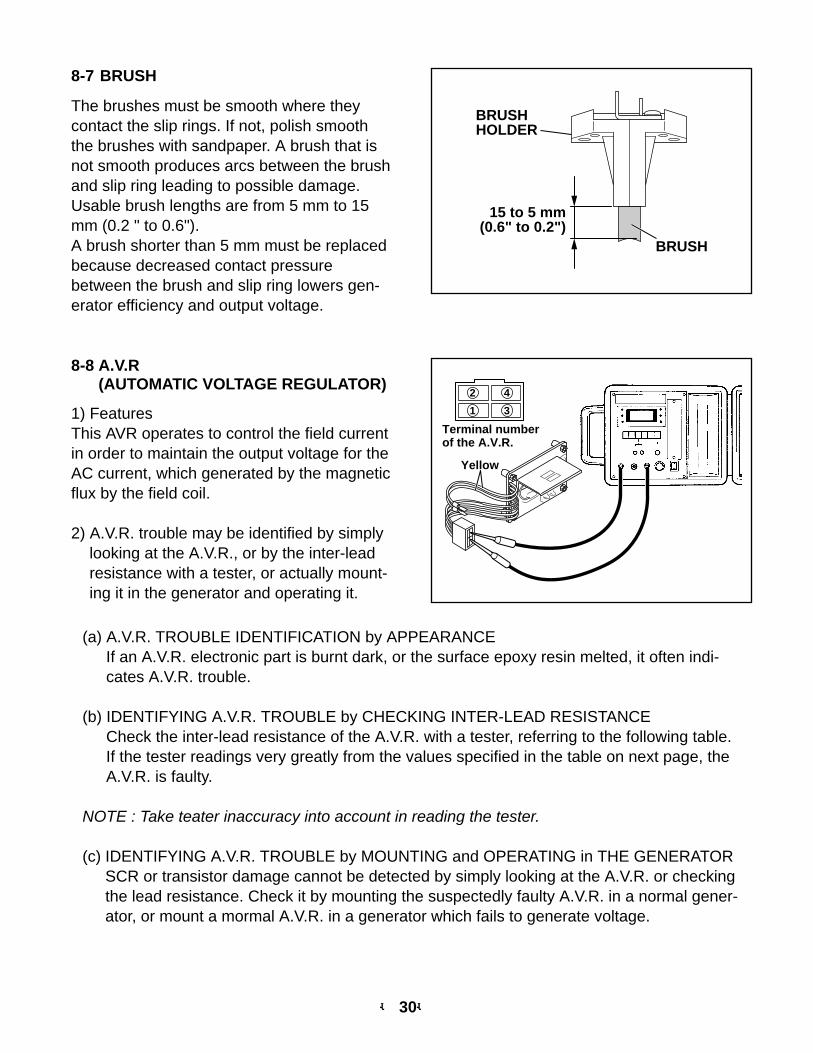
8-7 BRUSH
The brushes must be smooth where theycontact the slip rings. If not, polish smooththe brushes with sandpaper. A brush that isnot smooth produces arcs between the brushand slip ring leading to possible damage.Usable brush lengths are from 5 mm to 15mm (0.2 " to 0.6").A brush shorter than 5 mm must be replacedbecause decreased contact pressurebetween the brush and slip ring lowers gen-erator efficiency and output voltage.
15 to 5 mm(0.6" to 0.2")
BRUSH
BRUSHHOLDER
8-8 A.V.R(AUTOMATIC VOLTAGE REGULATOR)
1) FeaturesThis AVR operates to control the field currentin order to maintain the output voltage for theAC current, which generated by the magneticflux by the field coil.
2) A.V.R. trouble may be identified by simplylooking at the A.V.R., or by the inter-leadresistance with a tester, or actually mount-ing it in the generator and operating it.
2 4
1 3
Terminal numberof the A.V.R.
Yellow
(a) A.V.R. TROUBLE IDENTIFICATION by APPEARANCEIf an A.V.R. electronic part is burnt dark, or the surface epoxy resin melted, it often indi-cates A.V.R. trouble.
(b) IDENTIFYING A.V.R. TROUBLE by CHECKING INTER-LEAD RESISTANCECheck the inter-lead resistance of the A.V.R. with a tester, referring to the following table.If the tester readings very greatly from the values specified in the table on next page, theA.V.R. is faulty.
NOTE : Take teater inaccuracy into account in reading the tester.
(c) IDENTIFYING A.V.R. TROUBLE by MOUNTING and OPERATING in THE GENERATORSCR or transistor damage cannot be detected by simply looking at the A.V.R. or checkingthe lead resistance. Check it by mounting the suspectedly faulty A.V.R. in a normal gener-ator, or mount a mormal A.V.R. in a generator which fails to generate voltage.
-- 31--
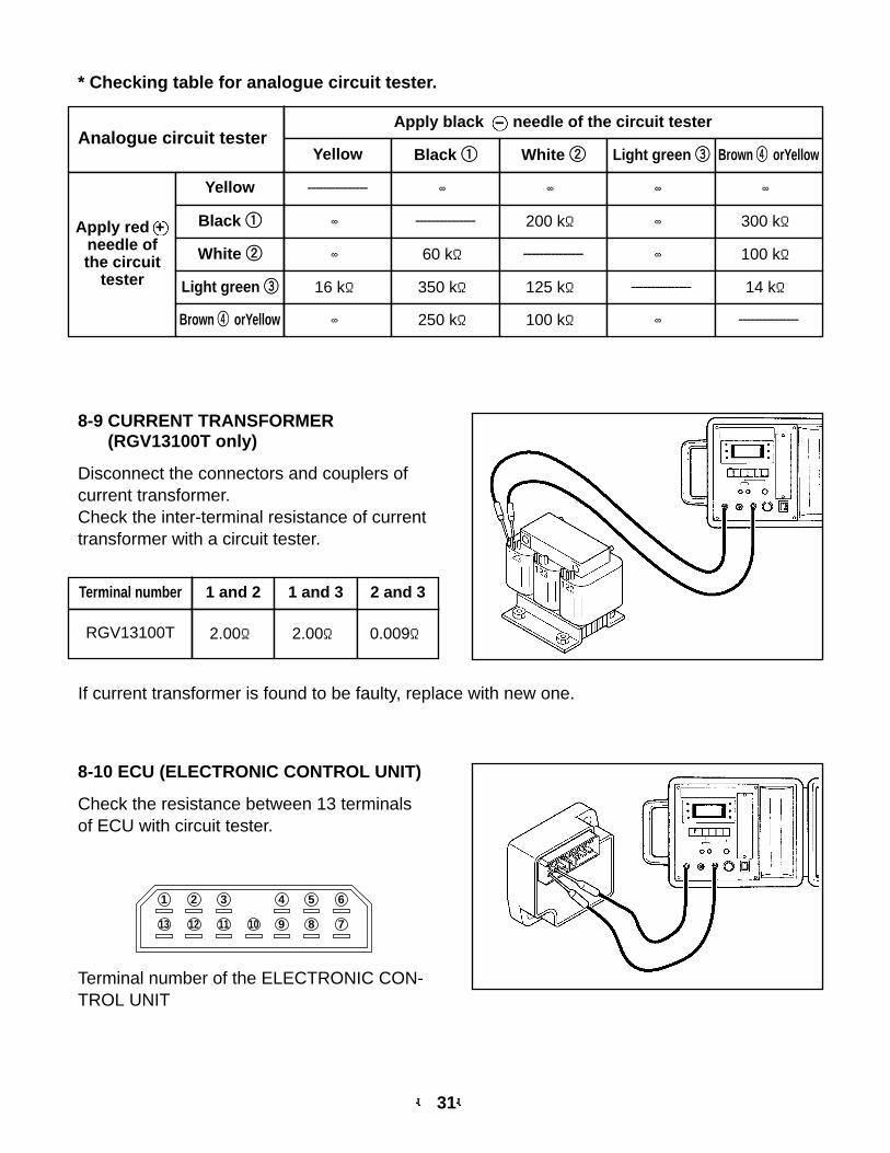
* Checking table for analogue circuit tester.
Analogue circuit testerApply black - needle of the circuit tester
Yellow Black 11 White 22 Light green 33 Brown 44 orYellow
Apply red +needle ofthe circuit
tester
Yellow --------------- ∞ ∞ ∞ ∞
Black 11 ∞ --------------- 200 kΩ ∞ 300 kΩ
White 22 ∞ 60 kΩ --------------- ∞ 100 kΩ
Light green 33 16 kΩ 350 kΩ 125 kΩ --------------- 14 kΩ
Brown 44 orYellow ∞ 250 kΩ 100 kΩ ∞ ---------------
8-9 CURRENT TRANSFORMER(RGV13100T only)
Disconnect the connectors and couplers ofcurrent transformer.Check the inter-terminal resistance of currenttransformer with a circuit tester.
If current transformer is found to be faulty, replace with new one.
8-10 ECU (ELECTRONIC CONTROL UNIT)
Check the resistance between 13 terminalsof ECU with circuit tester.
Terminal number of the ELECTRONIC CON-TROL UNIT
1013 7
1
11
3 6
812
2 5
9
4
Terminal number 1 and 2 1 and 3
RGV13100T 2.00Ω 2.00Ω 0.009Ω
2 and 3
-- 32--
Tester (-)
Tester( )
Pin No. 11 22 33 44 55 66 77 88 99 !!00 !!11 !!22 !!33
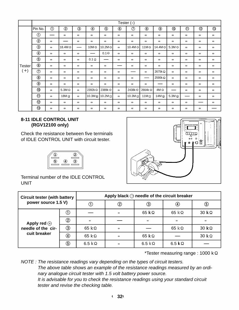
11 ------- ∞ ∞ ∞ ∞ ∞ ∞ ∞ ∞ ∞ ∞ ∞ ∞22 ∞ ------- ∞ ∞ ∞ ∞ ∞ ∞ ∞ ∞ ∞ ∞ ∞33 ∞ 18.4M ------- 10M 10.2M ∞ 10.4M 11M 14.4M 5.3M ∞ ∞ ∞44 ∞ ∞ ∞ ------- 0.1 ∞ ∞ ∞ ∞ ∞ ∞ ∞ ∞55 ∞ ∞ ∞ 0.1 ------- ∞ ∞ ∞ ∞ ∞ ∞ ∞ ∞66 ∞ ∞ ∞ ∞ ∞ ------- ∞ ∞ ∞ ∞ ∞ ∞ ∞77 ∞ ∞ ∞ ∞ ∞ ∞ ------- ∞ 2675k ∞ ∞ ∞ ∞88 ∞ ∞ ∞ ∞ ∞ ∞ ∞ ------- 2590k ∞ ∞ ∞ ∞99 ∞ ∞ ∞ ∞ ∞ ∞ ∞ ∞ ------- ∞ ∞ ∞ ∞!!00 ∞ 5.3M ∞ 2392k 2389k ∞ 2438k 2664k 4M ------- ∞ ∞ ∞!!11 ∞ 18M ∞ 10.3M 10.2M ∞ 10.3M 11M 14M 5.3M ------- ∞ ∞!!22 ∞ ∞ ∞ ∞ ∞ ∞ ∞ ∞ ∞ ∞ ∞ ------- ∞!!33 ∞ ∞ ∞ ∞ ∞ ∞ ∞ ∞ ∞ ∞ ∞ ∞ -------
*Tester measuring range : 1000 k
8-11 IDLE CONTROL UNIT(RGV12100 only)
Check the resistance between five terminalsof IDLE CONTROL UNIT with circuit tester.
45 3
1 2
NOTE : The resistance readings vary depending on the types of circuit testers.The above table shows an example of the resistance readings measured by an ordi-nary analogue circuit tester with 1.5 volt battery power source.It is advisable for you to check the resistance readings using your standard circuittester and revise the checking table.
Terminal number of the IDLE CONTROLUNIT
Circuit tester (with batterypower source 1.5 V)
Apply black 〇- needle of the circuit breaker
Apply red 〇+needle of the cir-
cuit breaker
11 22 33 44 55
11 ------- ∞ 65 65 30
22 ∞ ------- ∞ ∞ ∞
33 65 ∞ ------- 65 30
44 65 ∞ 65 ------- 30
55 6.5 ∞ 6.5 6.5 -------
-- 33--
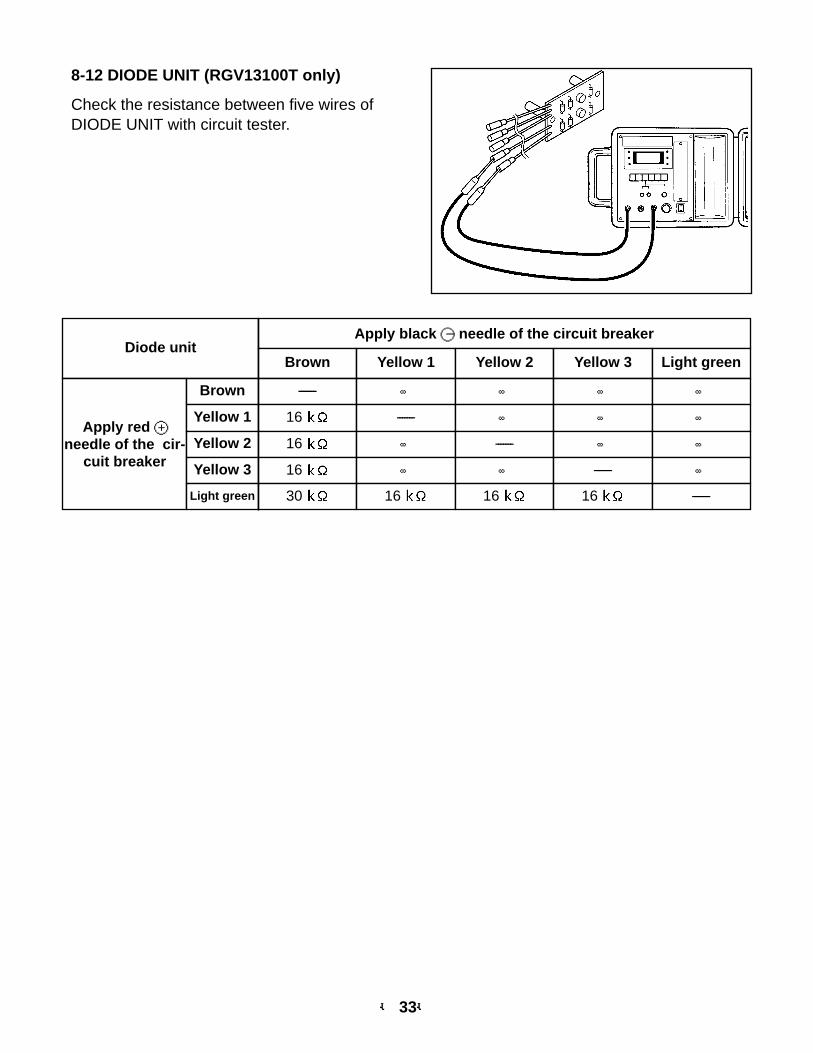
8-12 DIODE UNIT (RGV13100T only)
Check the resistance between five wires ofDIODE UNIT with circuit tester.
Diode unitApply black 〇- needle of the circuit breaker
Apply red 〇+needle of the cir-
cuit breaker
Brown Yellow 1 Yellow 2 Yellow 3 Light green
Brown ------- ∞ ∞ ∞ ∞
Yellow 1 16 ------- ∞ ∞ ∞
Yellow 2 16 ∞ ------- ∞ ∞
Yellow 3 16 ∞ ∞ ------- ∞
Light green 30 16 16 16 -------
-- 34--
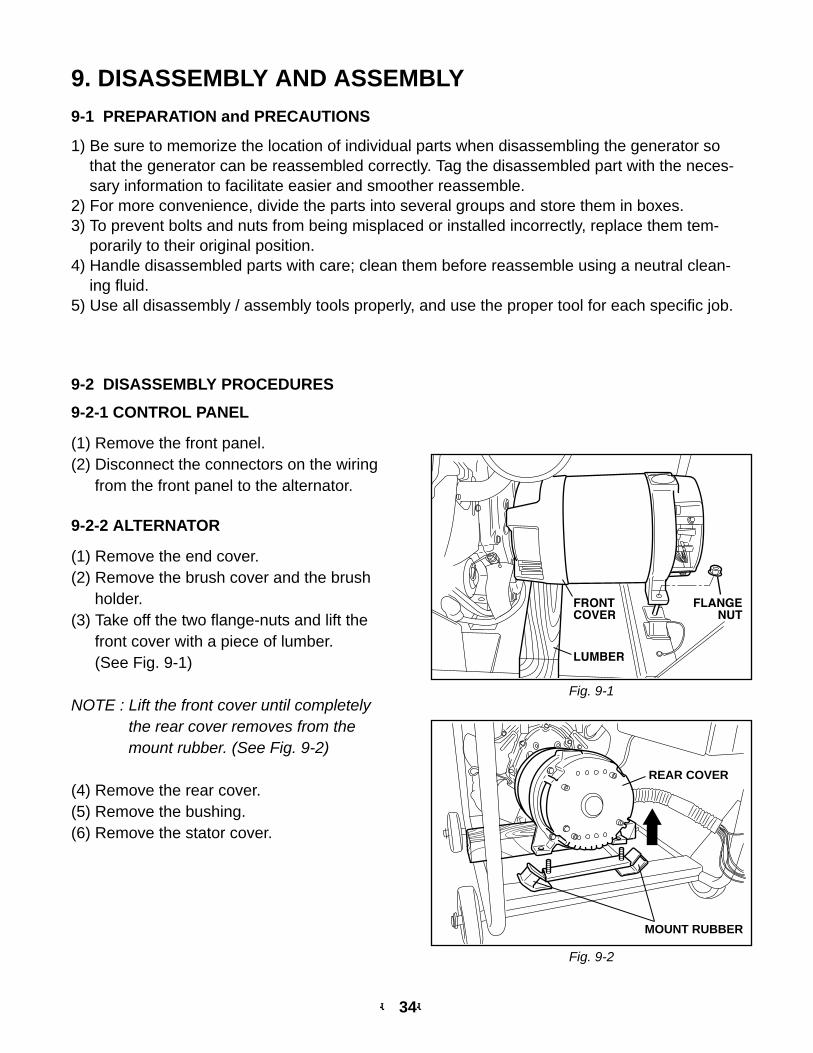
9. DISASSEMBLY AND ASSEMBLY9-1 PREPARATION and PRECAUTIONS
1) Be sure to memorize the location of individual parts when disassembling the generator sothat the generator can be reassembled correctly. Tag the disassembled part with the neces-sary information to facilitate easier and smoother reassemble.
2) For more convenience, divide the parts into several groups and store them in boxes.3) To prevent bolts and nuts from being misplaced or installed incorrectly, replace them tem-
porarily to their original position.4) Handle disassembled parts with care; clean them before reassemble using a neutral clean-
ing fluid.5) Use all disassembly / assembly tools properly, and use the proper tool for each specific job.
9-2 DISASSEMBLY PROCEDURES
9-2-1 CONTROL PANEL
(1) Remove the front panel.(2) Disconnect the connectors on the wiring
from the front panel to the alternator.
9-2-2 ALTERNATOR
(1) Remove the end cover.(2) Remove the brush cover and the brush
holder.(3) Take off the two flange-nuts and lift the
front cover with a piece of lumber. (See Fig. 9-1)
NOTE : Lift the front cover until completelythe rear cover removes from themount rubber. (See Fig. 9-2)
(4) Remove the rear cover.(5) Remove the bushing.(6) Remove the stator cover.
REAR COVER
MOUNT RUBBER
Fig. 9-1
Fig. 9-2
-- 35--
9-3 COMPONENT PARTS
For disassembling and assembling, the following illustrations show the major component partsand their configuration for (1) Generator assembly, (2) Control Box and (3) Fuel Tank and sys-tem.
The specified tightening torque is indicated in the illustration.
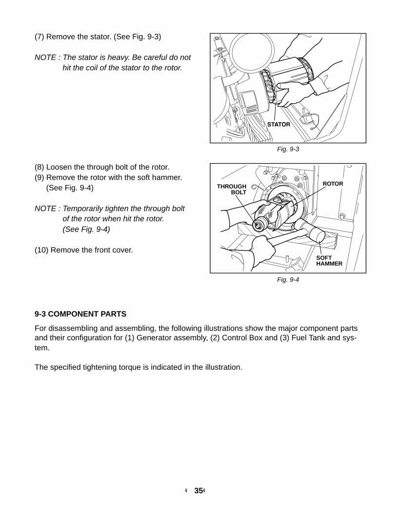
(8) Loosen the through bolt of the rotor.(9) Remove the rotor with the soft hammer.
(See Fig. 9-4)
NOTE : Temporarily tighten the through boltof the rotor when hit the rotor.(See Fig. 9-4)
(10) Remove the front cover.
ROTOR
SOFTHAMMER
THROUGHBOLT
Fig. 9-4
Fig. 9-3
(7) Remove the stator. (See Fig. 9-3)
NOTE : The stator is heavy. Be careful do nothit the coil of the stator to the rotor.
-- 36--
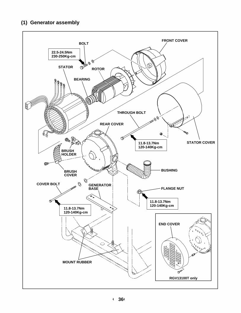
(1) Generator assembly
11.8-13.7Nm120-140Kg-cm
11.8-13.7Nm120-140Kg-cm
22.5-24.5Nm230-250Kg-cm
ROTORSTATOR
BEARING
THROUGH BOLT
REAR COVER
GENERATORBASE
BRUSHCOVER
BRUSHHOLDER
COVER BOLT
FRONT COVER
STATOR COVER
BUSHING
MOUNT RUBBER
FLANGE NUT
BOLT
11.8-13.7Nm120-140Kg-cm
END COVER
RGV13100T only
-- 37--
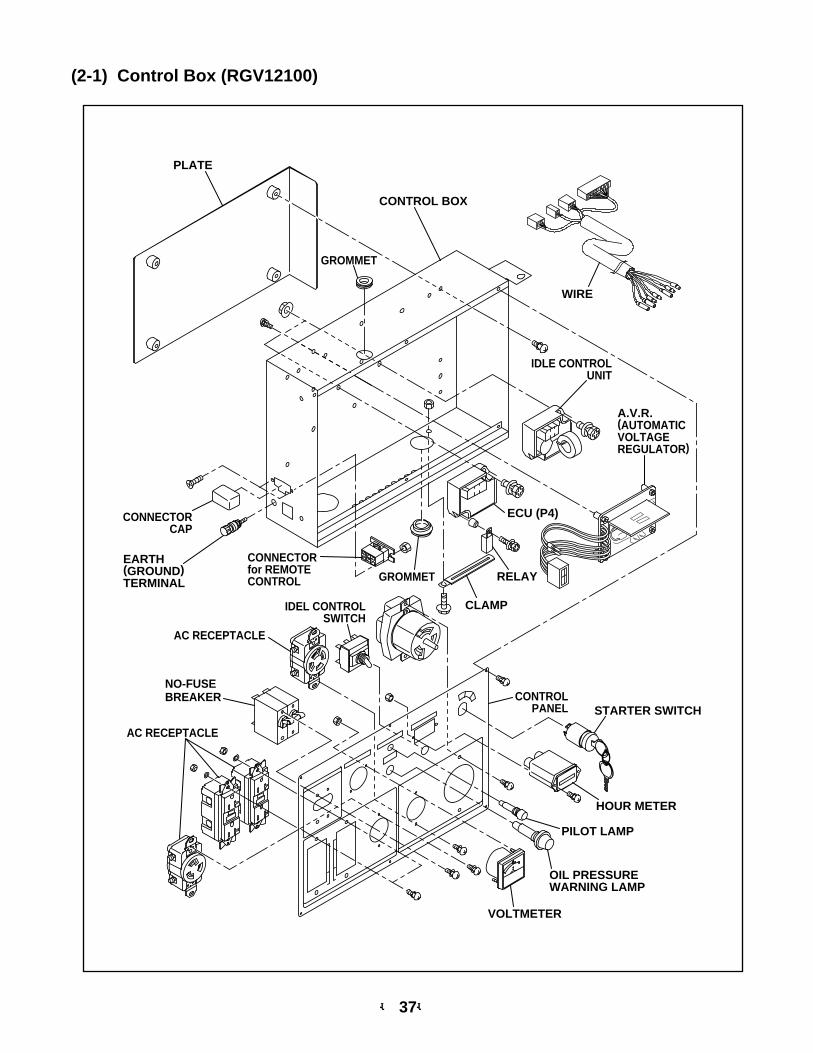
(2-1) Control Box (RGV12100)
CONTROL BOX
PLATE
NO-FUSEBREAKER
AC RECEPTACLE
CONNECTORCAP
A.V.R.(AUTOMATICVOLTAGEREGULATOR)
IDLE CONTROLUNIT
ECU (P4)
EARTH(GROUND)TERMINAL
VOLTMETER
STARTER SWITCHCONTROL
PANEL
OIL PRESSUREWARNING LAMP
GROMMET
IDEL CONTROLSWITCH
GROMMET
CLAMP
PILOT LAMP
HOUR METER
AC RECEPTACLE
CONNECTORfor REMOTECONTROL
WIRE
RELAY
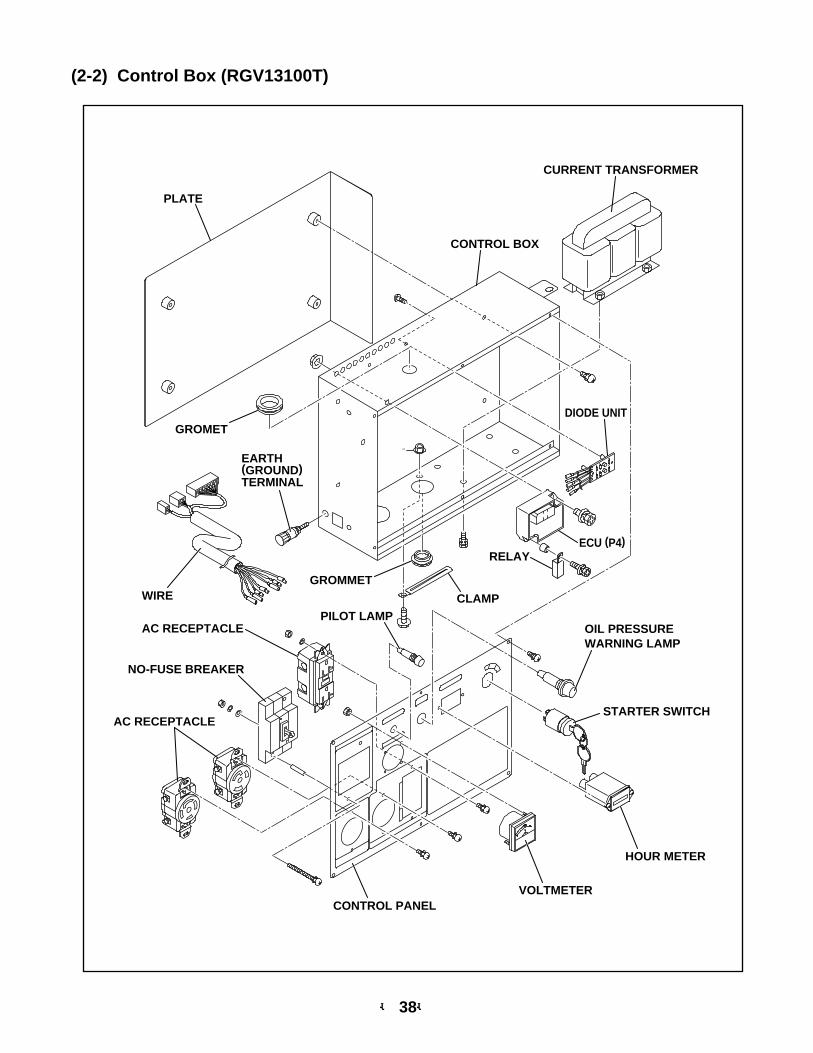
(2-2) Control Box (RGV13100T)
CURRENT TRANSFORMER
CONTROL BOX
GROMET
NO-FUSE BREAKER
AC RECEPTACLE
PILOT LAMP
STARTER SWITCH
OIL PRESSURE WARNING LAMP
GROMMET
CLAMP
PLATE
DIODE UNIT
EARTH(GROUND)TERMINAL
AC RECEPTACLE
WIRE
VOLTMETERCONTROL PANEL
HOUR METER
ECU (P4)RELAY
-- 38--
-- 39--
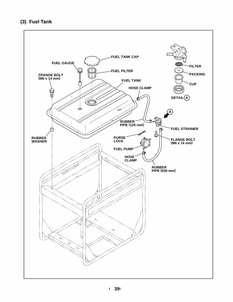
(3) Fuel Tank
FUEL GAUGE
FUEL TANK CAP
FUEL TANK
FILTER
PACKING
CUPHOSE CLAMP
HOSECLAMP
RUBBERPIPE (120 mm)
RUBBERPIPE (630 mm)
PURSELOCK
FUEL FILTERFRANGE BOLT(M6 x 14 mm)
RUBBERWASHER
FUEL PUMP
FLANGE BOLT(M6 x 14 mm)
FUEL STRAINER
A
DETAIL A
-- 40--
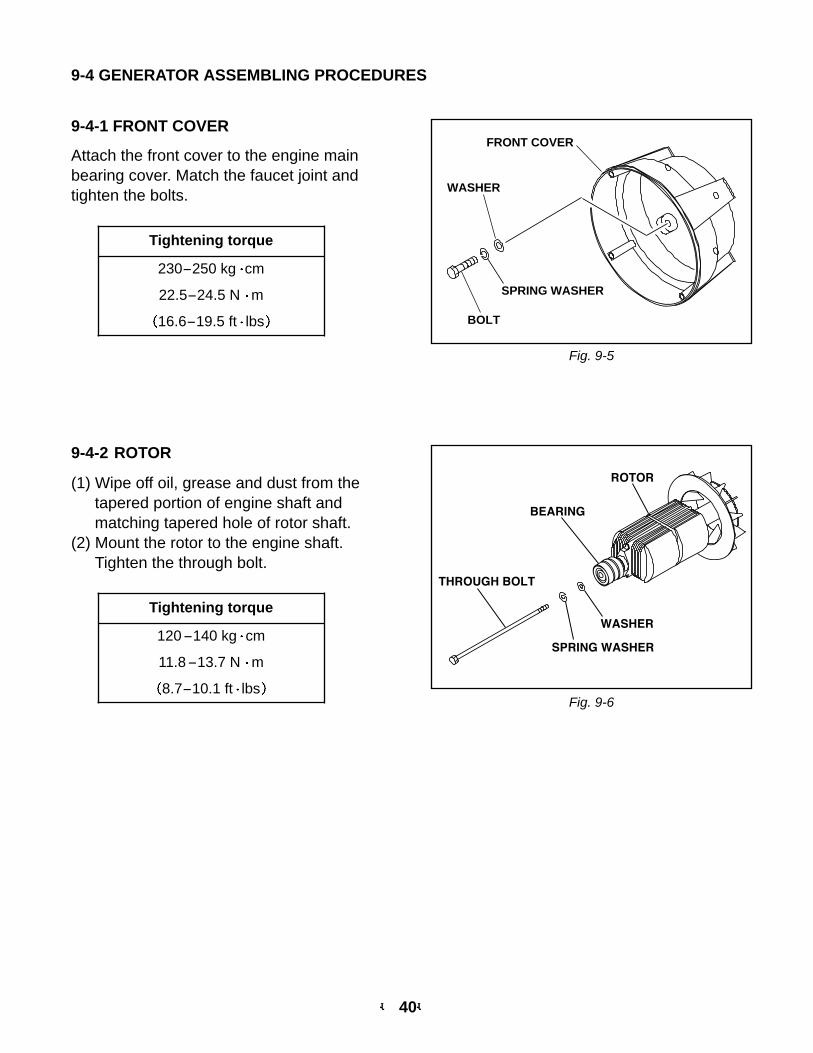
9-4-1 FRONT COVER
Attach the front cover to the engine mainbearing cover. Match the faucet joint andtighten the bolts.
FRONT COVER
BOLT
SPRING WASHER
WASHER
9-4-2 ROTOR
(1) Wipe off oil, grease and dust from thetapered portion of engine shaft andmatching tapered hole of rotor shaft.
(2) Mount the rotor to the engine shaft.Tighten the through bolt.
ROTOR
SPRING WASHER
WASHER
THROUGH BOLT
BEARING
9-4 GENERATOR ASSEMBLING PROCEDURES
Fig. 9-5
Fig. 9-6
Tightening torque
230-250 kg cm
22.5-24.5 N m
16.6-19.5 ft lbs
Tightening torque
120-140 kg cm
11.8-13.7 N m
8.7-10.1 ft lbs
-- 41--
Fig. 9-8
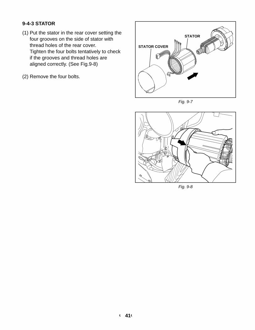
9-4-3 STATOR
(1) Put the stator in the rear cover setting thefour grooves on the side of stator withthread holes of the rear cover.Tighten the four bolts tentatively to checkif the grooves and thread holes arealigned correctly. (See Fig.9-8)
(2) Remove the four bolts.
STATOR COVER
STATOR
Fig. 9-7
-- 42--
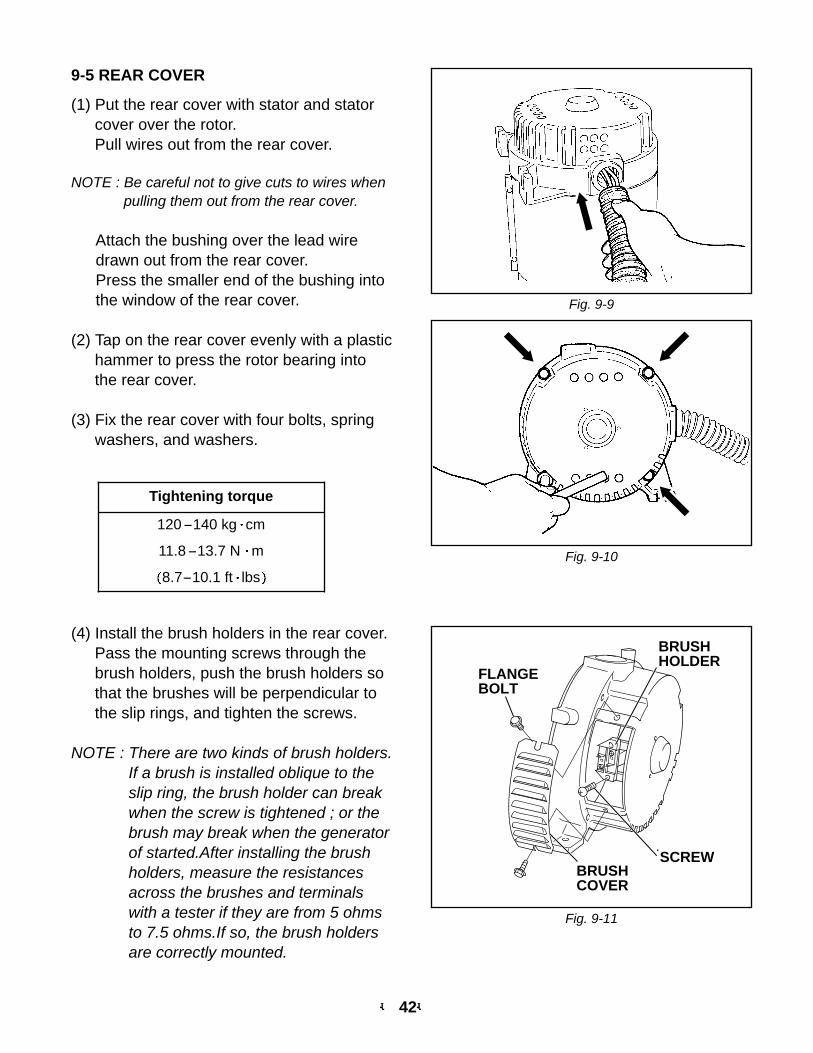
9-5 REAR COVER
(1) Put the rear cover with stator and statorcover over the rotor.Pull wires out from the rear cover.
NOTE : Be careful not to give cuts to wires whenpulling them out from the rear cover.
Attach the bushing over the lead wiredrawn out from the rear cover.Press the smaller end of the bushing intothe window of the rear cover.
(2) Tap on the rear cover evenly with a plastichammer to press the rotor bearing intothe rear cover.
(3) Fix the rear cover with four bolts, springwashers, and washers.
(4) Install the brush holders in the rear cover.Pass the mounting screws through thebrush holders, push the brush holders sothat the brushes will be perpendicular tothe slip rings, and tighten the screws.
NOTE : There are two kinds of brush holders.If a brush is installed oblique to theslip ring, the brush holder can breakwhen the screw is tightened ; or thebrush may break when the generatorof started.After installing the brushholders, measure the resistancesacross the brushes and terminalswith a tester if they are from 5 ohmsto 7.5 ohms.If so, the brush holdersare correctly mounted.
BRUSHCOVER
BRUSHHOLDER
FLANGEBOLT
SCREW
Fig. 9-9
Fig. 9-10
Fig. 9-11
Tightening torque
120-140 kg cm
11.8-13.7 N m
8.7-10.1 ft lbs
-- 43--
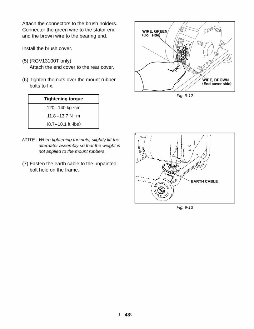
NOTE : When tightening the nuts, slightly lift thealternator assembly so that the weight isnot applied to the mount rubbers.
(7) Fasten the earth cable to the unpaintedbolt hole on the frame.
EARTH CABLE
Attach the connectors to the brush holders.Connector the green wire to the stator endand the brown wire to the bearing end.
Install the brush cover.
(5) (RGV13100T only)Attach the end cover to the rear cover.
(6) Tighten the nuts over the mount rubberbolts to fix.
Fig. 9-12
Fig. 9-13
Tightening torque
120-140 kg cm
11.8-13.7 N m
8.7-10.1 ft lbs
10. TROUBLESHOOTING
10-1 No AC output
* Checking the exciting coil for resistance. (RGV12100) (Refer to 8-6.)
If insulation is NG, replace exciting coil with new one.
* Checking the brush and slip ring of rotor for resistance. (Refer to 8-5 and 8-7.)
If insulation is NG, replace brush and slip ring with new one.
* Check stator for winding resistance between terminals. (Refer to 8-4.)
If stator is faulty, replace with new one.
* Checking stator for insulation resistance. (Refer to 7-3.)
If insulation is NG, replace stator with new one.
* Checking the A.V.R . (RGV12100) (Refer to 8-8.)
If insulation is NG, replace A.V.R with new one.
* Checking the diode unit and C.T . (RGV13100T) (Refer to 8-9 and 8-12.)
If insulation is NG, replace diode unit and C.T with new one.
10-2 AC Voltage is too high or too low
* Check engine speed.
Nominal engine speed at no load ; 3,700 to 3,750 rpm
If engine speed is too high or too low, adjust to the rated rpm.
* Check stator for winding resistance and insulation. (Refer to 8-4 and 7-3.)
* Check rotor for resistance and insulation. (Refer to 8-5 and 7-3.)
* Checking the idle control unit. (RGV12100) (Refer to 8-11.)
If insulation is NG, replace idle control unit with new one.
10-3 AC voltage is nominal at no-load, but load cannot be applied.
* Check engine speed.
If engine speed is low, adjust to the rated rpm.
* Check total wattage of appliances connected to generator.
If the generator is overloaded, reduce the load to the rated output of generator.
* Check appliance for trouble.
If the appliance is faulty, replace it.
* Check if engine is overheated.
If generator cooling air inlet and/or outlet is clogged with dirt, grass, chaff or other debris,
remove it.
* Check insulation of generator. (Refer to 7-3.)
-- 44--
-- 45--
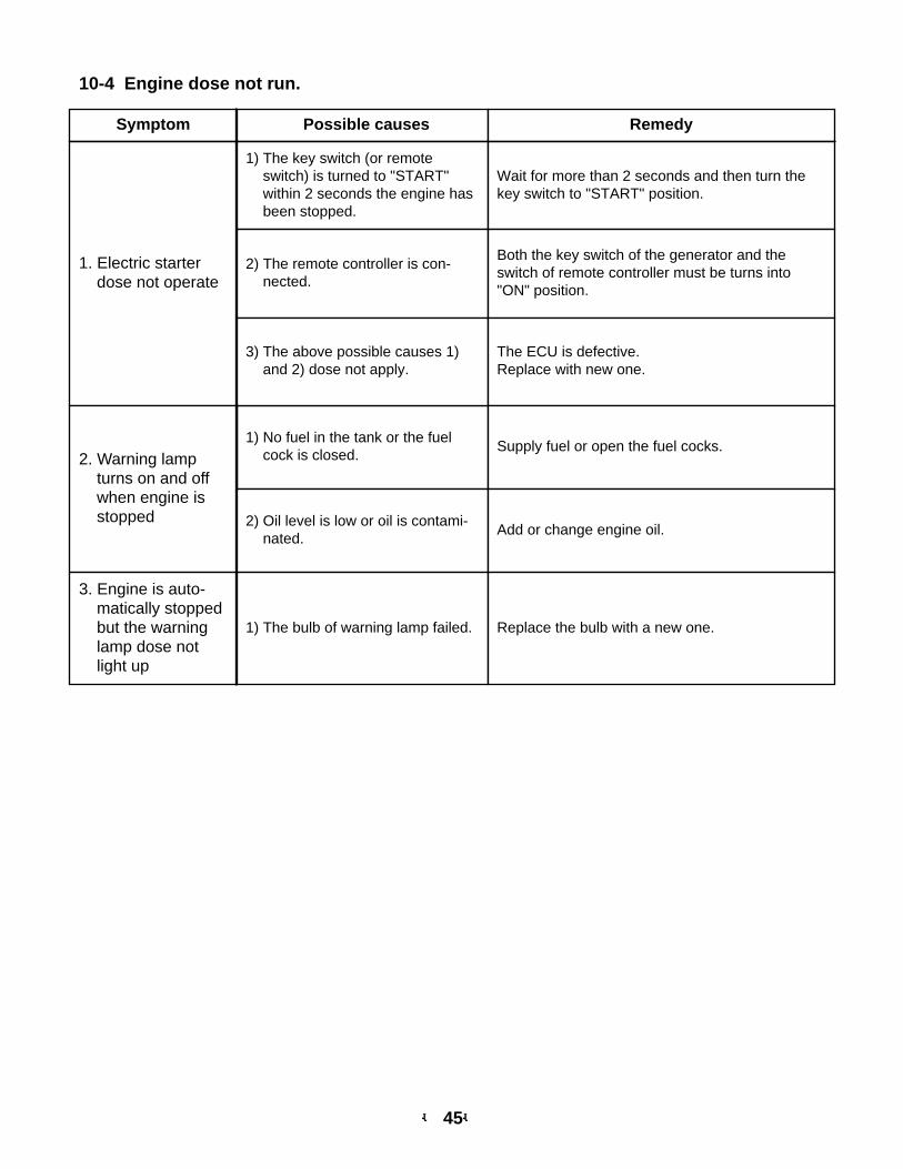
10-4 Engine dose not run.
Symptom Possible causes Remedy
1. Electric starterdose not operate
1) The key switch (or remoteswitch) is turned to "START"within 2 seconds the engine hasbeen stopped.
Wait for more than 2 seconds and then turn thekey switch to "START" position.
1) No fuel in the tank or the fuelcock is closed.
2) The remote controller is con-nected.
Both the key switch of the generator and theswitch of remote controller must be turns into"ON" position.
3) The above possible causes 1)and 2) dose not apply.
The ECU is defective.Replace with new one.
2. Warning lampturns on and offwhen engine isstopped
Supply fuel or open the fuel cocks.
2) Oil level is low or oil is contami-nated.
Add or change engine oil.
3. Engine is auto-matically stoppedbut the warninglamp dose notlight up
1) The bulb of warning lamp failed. Replace the bulb with a new one.
5 32
4
(AC output)
(AVR)
1
CONTROL BOX
Fuel cut
Ignition coil
Auto choke(Bimetal)
Electricstarter
Oil pressureswitch
Regulator
Magneticswitch
Chargecoil
Excitingcoil
- +
Battery 12VGrn/Y
Grn
LBlu
Gry W
Keyswitch
to earthterminal
ST Relay
Connector(Remote control)
Gry
R15
Blk
15
Grn
WWW
Blk/W
Gry
Gry
Blk
R
Blk/WBlk
R
Grn/YGrn/Y
Grn
Grn
OrgR
Org
Org
LBlu
LBlu
LBlu
BrnY
Org
R
W
W
W
WW
WW
OFF-M +M B L.IG ST
ONSTART
R/W
Idlesolenoid 1
Electronic control unit
2
13
3
12
4
11
5
10
6
9 8 7
Blk
YY
Blk
Grn/Y
Grn/YIdle controlswitch
Idlecontrol
unit
Oil pressurewarning lamp
(Red)
LGrn
Org
Blk
Blu
Blk
R
R
Blk
W W
W
LGrn
Grn/Y
Grn/Y
Grn
/Y
Grn/Y
Brm
CONTROL BOXGENERATOR
No-fuse breaker
Vol
tmet
er
Hou
r m
eter
Pilo
t lam
p
VHr PL
Earth(Ground)terminal
Brush
AuxiliaryWinding
FieldWinding
AC
Win
ding
AC
Win
ding
AVR
Exciting coil(Engine)
Idle
co
ntro
lun
it
AC otuputreceptacle(120V)
AC output receptacle(120V)
AC output receptacle(120/240V)
AC output receptacle(120/240V)
YY
REC1 REC2
REC3
REC4
REC5
W W
W W
X XY Y
H H
G
G GG G
Key switch -MIdle control unit 3
Blk
YY
WWLGrnBrm
-- 46--
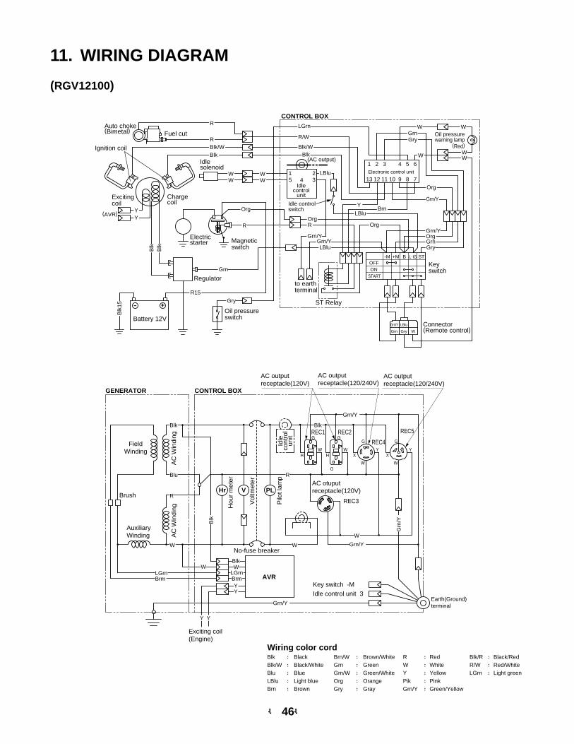
Wiring color cord
LGrnR/WBlk/RBlk Black Brn/W Brown/White R Red
Blk/W Black/White Grn Green W WhiteBlu Blue Grn/W Green/White Y YellowLBlu Light blue Org Orange Pik PinkBrn Brown Gry Gray Grn/Y Green/Yellow
:::::
:::::
:::::
:::
Light greenRed/WhiteBlack/Red
11. WIRING DIAGRAM
(RGV12100)
-- 47--
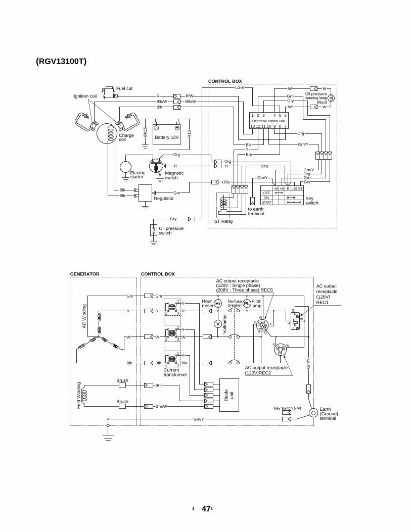
(RGV13100T)
CONTROL BOX
1
Fuel cut
Ignition coil
Electricstarter
Oil pressureswitch
Regulator
Magneticswitch
Oil pressurewarning lamp
(Red)
Chargecoil
Electronic control unit
- +
Battery 12VBlk
15
R15
LGrn
Gry
BlkBlk
Grn
2
13
3
12
4
11
5
10
6
9 8 7
R
W
W
W
W
Org
Grn/Y
OrgR
Org
Blk/WBlk/WR/W
GryGrn
Blk
R
Blk
Keyswitch
to earthterminal
OFF-M +M B L.IG ST
ONSTART
ST Relay
GryGrnOrgGrn/Y
Grn/Y
YBrn
Org
LBlu
R
Grn
W
Blk
R
W
Blk
Brn
Grn/W
Y
R
Y
W
Y
Blk
GENERATOR CONTROL BOX
V
PLHr
AC
Win
ding
Fel
d W
indi
ng
Brush
Brush Dio
deun
it
AC outputreceptacle(120V)REC1
AC output receptacle(120V : Single phase)(208V : Three phase) REC5
AC output receptacle(120V)REC2
WX
W
W
H
G
G
G
Y
Z
Grn/Y
Grn
/Y
Vol
tmet
er
No-fusebreaker
Earth(Ground)terminal
Pilotlamp
Hourmeter
Grn
Key switch (-M)
Currenttransformer
1
2 3
1
2 3
1
2 3

PRINTED IN THE USA© Copyright 2001 Robin America, Inc.
���� �������� ������������� ��������������������������������� �!��������������e-mail: [email protected] • www.robinamerica.com