Embed Size (px)
Citation preview
CHAPTER 3
SMALL ARMS
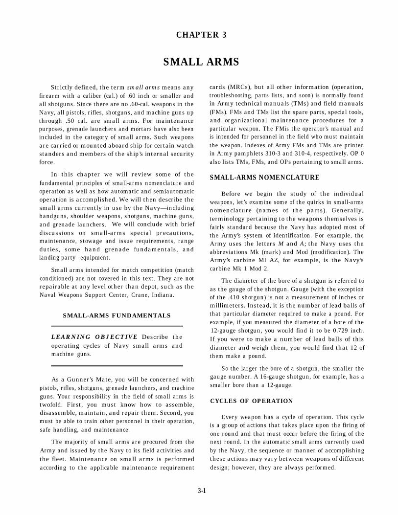
Strictly defined, the term small arms means anyfirearm with a caliber (cal.) of .60 inch or smaller andall shotguns. Since there are no .60-cal. weapons in theNavy, all pistols, rifles, shotguns, and machine guns upthrough .50 cal. are small arms. For maintenancepurposes, grenade launchers and mortars have also beenincluded in the category of small arms. Such weaponsare carried or mounted aboard ship for certain watchstanders and members of the ship’s internal securityforce.
In this chapter we will review some of thefundamental principles of small-arms nomenclature andoperation as well as how automatic and semiautomaticoperation is accomplished. We will then describe thesmall arms currently in use by the Navy—includinghandguns, shoulder weapons, shotguns, machine guns,and grenade launchers. We will conclude with briefdiscussions on small-arms special precautions,maintenance, stowage and issue requirements, rangeduties, some hand grenade fundamentals, andlanding-party equipment.
Small arms intended for match competition (matchconditioned) are not covered in this text. They are notrepairable at any level other than depot, such as theNaval Weapons Support Center, Crane, Indiana.
SMALL-ARMS FUNDAMENTALS
LEARNING OBJECTIVE Describe theoperating cycles of Navy small arms andmachine guns.
As a Gunner’s Mate, you will be concerned withpistols, rifles, shotguns, grenade launchers, and machineguns. Your responsibility in the field of small arms istwofold. First, you must know how to assemble,disassemble, maintain, and repair them. Second, youmust be able to train other personnel in their operation,safe handling, and maintenance.
The majority of small arms are procured from theArmy and issued by the Navy to its field activities andthe fleet. Maintenance on small arms is performedaccording to the applicable maintenance requirement
cards (MRCs), but all other information (operation,troubleshooting, parts lists, and soon) is normally foundin Army technical manuals (TMs) and field manuals(FMs). FMs and TMs list the spare parts, special tools,and organizational maintenance procedures for aparticular weapon. The FMis the operator’s manual andis intended for personnel in the field who must maintainthe weapon. Indexes of Army FMs and TMs are printedin Army pamphlets 310-3 and 310-4, respectively. OP 0also lists TMs, FMs, and OPs pertaining to small arms.
SMALL-ARMS NOMENCLATURE
Before we begin the study of the individualweapons, let’s examine some of the quirks in small-armsnomenclature (names of the parts). Generally,terminology pertaining to the weapons themselves isfairly standard because the Navy has adopted most ofthe Army’s system of identification. For example, theArmy uses the letters M and A; the Navy uses theabbreviations Mk (mark) and Mod (modification). TheArmy’s carbine Ml AZ, for example, is the Navy’scarbine Mk 1 Mod 2.
The diameter of the bore of a shotgun is referred toas the gauge of the shotgun. Gauge (with the exceptionof the .410 shotgun) is not a measurement of inches ormillimeters. Instead, it is the number of lead balls ofthat particular diameter required to make a pound. Forexample, if you measured the diameter of a bore of the12-gauge shotgun, you would find it to be 0.729 inch.If you were to make a number of lead balls of thisdiameter and weigh them, you would find that 12 ofthem make a pound.
So the larger the bore of a shotgun, the smaIler thegauge number. A 16-gauge shotgun, for example, has asmaller bore than a 12-gauge.
CYCLES OF OPERATION
Every weapon has a cycle of operation. This cycleis a group of actions that takes place upon the firing ofone round and that must occur before the firing of thenext round. In the automatic small arms currently usedby the Navy, the sequence or manner of accomplishingthese actions may vary between weapons of differentdesign; however, they are always performed.
3-1
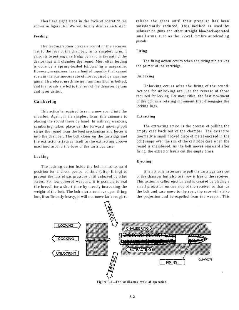
There are eight steps in the cycle of operation, asshown in figure 3-1. We will briefly discuss each step.
Feeding
The feeding action places a round in the receiverjust to the rear of the chamber. In its simplest form, itamounts to putting a cartridge by hand in the path of thedevice that will chamber the round. Most often feedingis done by a spring-loaded follower in a magazine.However, magazines have a limited capacity that cannotsustain the continuous rate of fire required by machineguns. Therefore, machine gun ammunition is belted,and the rounds are fed to the rear of the chamber by camand lever action.
Cambering
This action is required to ram a new round into thechamber. Again, in its simplest form, this amounts toplacing the round there by hand. In military weapons,cambering takes place as the forward moving boltstrips the round from the feed mechanism and forces itinto the chamber. The bolt closes on the cartridge andthe extractor attaches itself to the extracting groovemachined around the base of the cartridge case.
Locking
The locking action holds the bolt in its forwardposition for a short period of time (after firing) toprevent the loss of gas pressure until unlocked by otherforces. For low-powered weapons, it is possible to sealthe breech for a short time by merely increasing theweight of the bolt. The bolt starts to move upon firing;but, if sufficiently heavy, it will not move far enough to
release the gases until their pressure has beensatisfactorily reduced. This method is used bysubmachine guns and other straight blowback-operatedsmall arms, such as the .22-cal. rimfire autoloadingpistols.
Firing
The firing action occurs when the tiring pin strikesthe primer of the cartridge.
Unlocking
Unlocking occurs after the firing of the round.Actions for unlocking are just the reverse of thoserequired for locking. For most rifles, the first movementof the bolt is a rotating movement that disengages thelocking lugs.
Extracting
The extracting action is the process of pulling theempty case back out of the chamber. The extractor(normally a small hooked piece of metal encased in thebolt) snaps over the rim of the cartridge case when theround is chambered. As the bolt moves rearward afterfiring, the extractor hauls out the empty brass.
Ejecting
It is not only necessary to pull the cartridge case outof the chamber but also to throw it free of the receiver.This action is called ejection and is created by placing asmall projection on one side of the receiver so that, asthe bolt and case move to the rear, the case will strikethe projection and be expelled from the weapon. This
Figure 3-1.—The small-arms cycle of operation.
3-2
method is used in the .45-cal. pistol. Another method ofaccomplishing this step is to incorporate a spring-loadedejector in the face of the bolt. In this arrangement thecase is flipped from the weapon as soon as its forwardend clears the chamber. This method is used in the M14rifle.
Cocking
Cocking is the retraction of the firing mechanism(firing pin and hammer) against spring pressure so thatthere will be sufficient energy to fire the cartridge in thenext cycle of operation. The firing pin, hammer or, insome cases, the bolt itself is held in a cocked positionby a piece called the sear.
Firing is initiated by squeezing a trigger. Thismovement trips the sear, releasing the firing mechanism(firingpin, hammer or, in automatic weapons, such partsas the bolt group or slide), causing it to move forwardwith enough force to discharge the round.
AUTOMATIC AND SEMIAUTOMATICFIRING SYSTEMS
LEARNING OBJECTIVE Discuss theoperation and maintenance of Navy small arms.
A semiautomatic weapon unlocks, extracts, ejects,cocks, and reloads automatically. However, the triggermust be pulled each time to fire a round. By thisdefinition, the .45-cal. M1911A1 pistol issemiautomatic, though often called automatic. A fullyautomatic weapon keeps on firing as long as the triggeris kept pulled.
Two examples of weapons that can be fired bothautomatically and semiautomatically are the 7.62-mmM14 rifle and the 5.56-mm M16 rifle.
SMALL-ARMS OPERATINGPRINCIPLES
Automatic and semiautomatic weapons areclassified on the basis of how they obtain the energyrequired for operation. Fundamentally, small armsobtain the energy from the forces that accompany theexplosion created when around of ammunition is fired.The use of these forces does not reduce the effectivenessof the weapon but uses otherwise wasted energy.
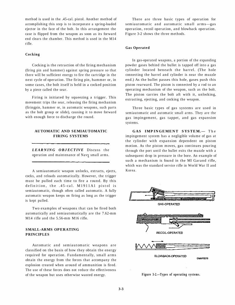
There are three basic types of operation forsemiautomatic and automatic small arms—gasoperation, recoil operation, and blowback operation.Figure 3-2 shows the three methods.
Gas Operated
In gas-operated weapons, a portion of the expandingpowder gases behind the bullet is tapped off into a gascylinder located beneath the barrel. (The holeconnecting the barrel and cylinder is near the muzzleend.) As the bullet passes this hole, gases push thispiston rearward. The piston is connected by a rod to anoperating mechanism of the weapon, such as the bolt.The piston carries the bolt aft with it, unlocking,extracting, ejecting, and cocking the weapon.
Three basic types of gas systems are used insemiautomatic and automatic small arms. They are thegas impingement, gas tappet, and gas expansionsystems.
GAS IMPINGEMENT SYSTEM.— T h eimpingement system has a negligible volume of gas atthe cylinder with expansion dependent on pistonmotion. As the piston moves, gas continues pouringthrough the port until the bullet exits the muzzle with asubsequent drop in pressure in the bore. An example ofsuch a mechanism is found in the Ml Garand rifle,which was the standard service rifle in World War II andKorea.
Figure 3-2.—Types of operating systems.
3-3
GAS TAPPET SYSTEM.— The gas tappet systemis an impingement system with a short piston travel. Itis often referred to as a gas short stroke system. Anexample of such a mechanism is found in the Ml andM1A1 .30-cal. carbine. In some tappet mechanisms, thepiston only taps the lock mechanism open and exerts noforce to recoiling components.
GAS EXPANSION SYSTEM.— The gasexpansion system, in contrast to the impingementsystem, has an appreciable initial volume of gas in itsexpansion chamber. This requires more time topressurize the chamber and also more time to exhaustthe gas by selection of port size and location as therequired pressurized gas can be drained from the bore.
There is also a cutoff expansion that is similar to thedirect expansion system, except for a valve that closesthe port after the piston moves. As the pressure buildsup to a specific value, the piston moves, closing the portand leaving the gas to expand, providing the force effortneeded to operate the moving components. The7.62-mm M14 rifle uses this type of operation.
Recoil Operated
As a round is fired, high pressures develop behindthe bullet and force it down the barrel. The force behindthe bullet is also directed rearward against the breech.If the barrel and bolt are secured to one another, theentire force of recoil is felt on the shooter’s shoulder.But, by designing the barrel and breech assembly so thatthey can slide in the frame or receiver, the energy of therear moving assembly can be used to compress springs,move levers, and soon, necessary to complete the cycleof operation.
Generally, in recoil-operated weapons, the barreland the bolt move rearward together for a short distance.Then the barrel is stopped and the bolt (now unlocked)continues to the rear against spring pressure until theempty case is ejected. The force of recoil is also usedto cock the weapon and compress the spring, returningthe bolt to its firing position and cambering a newround in the process.
There are two basic methods of recoil operation forsemiautomatic and automatic small arms. They are thelong-recoil (Browning) and short-recoil (Maxim)methods.
LONG-RECOIL METHOD.— The dynamics oflong-recoil-operated weapons are similar to straightblowback operation, except that the barrel, breechblock,and component parts recoil together for the completerecoil cycle. This recoil distance must be greater thanthe length of the complete round. At the end of the recoilstroke, the bolt is held while the barrel counterrecoilsalone. One particular note of importance on thelong-recoil type of operation is that ejection takes placeon counterrecoil instead of recoil. An example of along-recoil weapon is the Browning designed,Remington model 11 shotgun, used by the Navy beforeand during World War II.
SHORT-RECOIL METHOD.— The dynamics ofshort-recoil-operated weapons approach those of theretarded blowback types more nearly than long-recoil.The bolt latch is not released until the propellant gasesbecome ineffective to eliminate all blowbacktendencies. After unlatching (unlocking), the boltcontinues recoiling and in some mechanisms isaccelerated by mechanical or gas systems. The barrel isarrested by spring, buffer, stop, or a combination ofthese and is caused to return to battery by these or thecounterrecoiling components. Examples ofshort-recoil-operated weapons are the .45-cal. pistol andthe Browning machine gun.
Blowback Operated
There are some similarities between recoil- andblowback-operated weapons. But there are severalmajor differences. In recoil operation, the bolt andbarrel are locked together until the bullet has left thebarrel and most of the recoil thrust is spent. Thecombined thrust of the recoiling barrel, bolt, and someother parts is used to operate the weapon. In blowback(inertia) operation, however, the bolt is not locked to thebarrel and, inmost cases, the barrel does not recoil. Thebolt is held closed by spring pressure and the mass ofthe breechblock. The initial blow of the explodingcartridge starts the bolt moving rearward, but the weightof the bolt is such that it does not allow the chamber tobe entirely opened until the round has left the bore.Action by a recoil spring returns the bolt to the CLOSEDposition, cambering a new round.
Thus the weight of the breech bolt is an importantfactor in the des ign and operat ion o f ablowback-operated weapon. When used withlow-powered ammunition, it is a suitable arrangement.A military rifle, however, using the standard .30-cal.cartridge and the blowback action, would require a27-pound breechblock.
3-4
Besides the submachine gun, many types ofso-called pocket automatic pistols and .22-cal.automatic rifles use blowback operations.
There are variants in the methods used for each ofthese types to operate the mechanism for blowback.These are the straight blowback, retarded blowback, andaccelerated blowback methods.
STRAIGHT BLOWBACK METHOD.—Straight blowback is the most elementary and simple.It uses recoil energy from the firing of a round ofammunition to operate the mechanism of the weaponand extract the fired case, eject it against spring tension,and return the mechanism to firing position again. This,in turn, picks up an unfired round from a magazine andchambers it. Straight blowback is used in weapons thatfire ammunition of fairly low power, such as pistolammunition and .22-cal. rimfire rifle cartridges. Thebolt slide or breechblock is fairly heavy in theseweapons when compared to the weight of the bullet andpower of the cartridge. Therefore, the mechanism willstay closed (but not locked) momentarily until the bulletgets free of the barrel and pressure is subdued to allowextraction. All submachine guns and semiautomatic.22-cal. rimfire pistols use straight blowback for theiroperation.
RETARDED BLOWBACK METHOD.— Anexample of retarded blowback is found in themechanism of the original Thompson submachine gun.This is based on the principle of operation that the recoilforce exerted on the mechanism must overcome someform of mechanical disadvantage, momentarily holdingthe breechblock closed until the bullet had cleared themuzzle of the weapon. However, this was later foundunnecessary if the bolt or breechbhck was of sufficientweight. The Thompson Ml-Al submachine gun(formerly used by the Navy) uses straight blowback ashave all submachine guns designed since that time.
ACCELERATED BLOWBACK METHOD.—An example of accelerated blowback is found in the.22-cal. rimfire Colt Ace semiautomatic pistol. In thispistol, the Williams floating chamber, apart of the barrelon firing a round of ammunition, moves withaccelerated force against the mechanism (in this case,the fairly heavy slide and its components), providingsufficient energy to operate the component parts of a.45-cal. pistol with .22-cal. rirnfire ammunition.
Range and Rate of Fire
Some other important terms that apply to small armsdescribe their range and rate of fire. The range of a
weapon is stated in terms of maximum range andmaximum effective range. The rate of fire of anautomatic weapon is stated as the cyclic rate of fire andthe sustained rate of fire.
MAXIMUM RANGE.— Maximum range is thegreatest distance that the projectile will travel.
M A X I M U M E F F E C T I V E R A N G E . —Maximum effective range is the greatest distance atwhich a weapon may be expected to fire accurately toinflict damage or casualties.
CYCLIC RATE OFFIRE.— The cyclic rate of fireis the maximum rate at which a weapon will fire inautomatic operation, stated in rounds per minute (rpm).
SUSTAINED RATE OF FIRE.— The sustainedrate of fire of a weapon is normally stated in a chart. Thechart correlates the average number of rounds fired perminute with the number of minutes this rate can besustained without damage to the weapon.
HANDGUNS
LEARNING OBJECTIVE Describe the cycleof operation, disassembly, assembly, andsafeties of Navy handguns.
Three standard issue handguns are used by the Navytoday-the .45-cal. semiautomatic pistol, the 9-mm M9semiautomatic pistol, and the .38-cal. Smith and Wesson(S&W) revolver. In this section we will provide youwith information concerning the description, operation,and maintenance of these three pistols.
M1911A1 .45-CALIBER SEMIAUTOMATICPISTOL
During the uprising of the Moro tribes in thePhilippines during the early 1900s, it was found that thetribesmen often were not stopped when hit by bulletsfrom the .38-cal. side arms then used by Americantroops. This lack of stopping power was one of thefactors that led to the adoption in 1911 of the .45-cal.semiautomatic pistol as the official military side arm.
The .45-cal. semiautomatic pistol was designed andpatented by John M. Browning, who was probably thegreatest inventor of automatic weapons in the world.The original model 1911 differs only in one detail fromthe current model 1911A1. The 1911A1 includes anadditional safety feature (the grip safety). Other thanthis, the operation of the two models is identical.
3-5
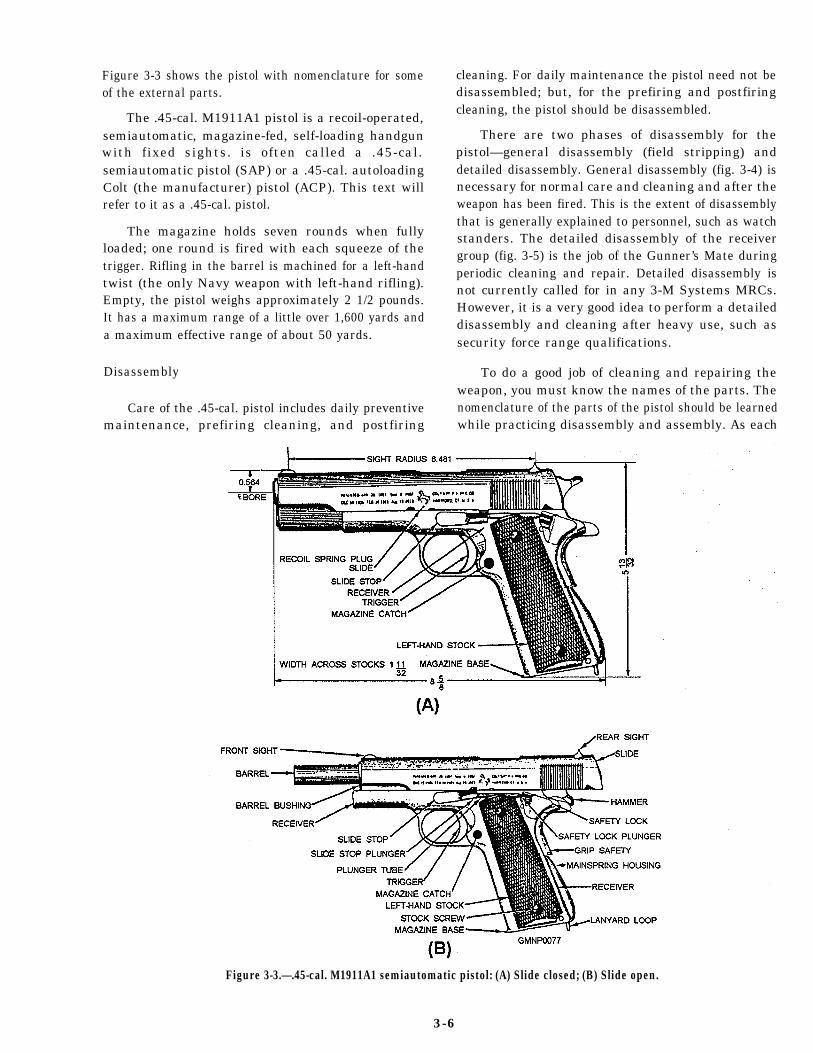
Figure 3-3 shows the pistol with nomenclature for someof the external parts.
The .45-cal. M1911A1 pistol is a recoil-operated,semiautomatic, magazine-fed, self-loading handgunwith fixed sights. is often called a .45-cal.semiautomatic pistol (SAP) or a .45-cal. autoloadingColt (the manufacturer) pistol (ACP). This text willrefer to it as a .45-cal. pistol.
The magazine holds seven rounds when fullyloaded; one round is fired with each squeeze of thetrigger. Rifling in the barrel is machined for a left-handtwist (the only Navy weapon with left-hand rifling).Empty, the pistol weighs approximately 2 1/2 pounds.It has a maximum range of a little over 1,600 yards anda maximum effective range of about 50 yards.
Disassembly
Care of the .45-cal. pistol includes daily preventivemaintenance, prefiring cleaning, and postfiring
cleaning. For daily maintenance the pistol need not bedisassembled; but, for the prefiring and postfiringcleaning, the pistol should be disassembled.
There are two phases of disassembly for thepistol—general disassembly (field stripping) anddetailed disassembly. General disassembly (fig. 3-4) isnecessary for normal care and cleaning and after theweapon has been fired. This is the extent of disassemblythat is generally explained to personnel, such as watchstanders. The detailed disassembly of the receivergroup (fig. 3-5) is the job of the Gunner’s Mate duringperiodic cleaning and repair. Detailed disassembly isnot currently called for in any 3-M Systems MRCs.However, it is a very good idea to perform a detaileddisassembly and cleaning after heavy use, such assecurity force range qualifications.
To do a good job of cleaning and repairing theweapon, you must know the names of the parts. Thenomenclature of the parts of the pistol should be learnedwhile practicing disassembly and assembly. As each
Figure 3-3.—.45-cal. M1911A1 semiautomatic pistol: (A) Slide closed; (B) Slide open.
3-6
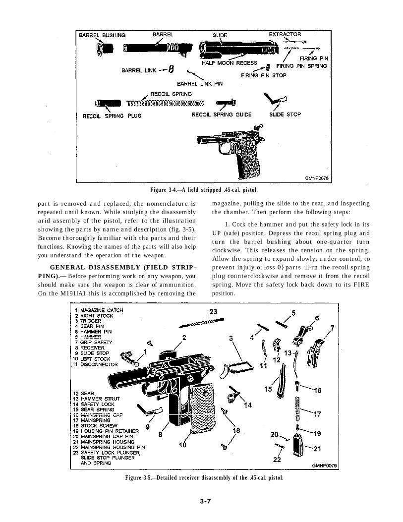
Figure 3-4.—A field stripped .45-cal. pistol.
part is removed and replaced, the nomenclature is magazine, pulling the slide to the rear, and inspectingrepeated until known. While studying the disassembly the chamber. Then perform the following steps:arid assembly of the pistol, refer to the illustration 1. Cock the hammer and put the safety lock in itsshowing the parts by name and description (fig. 3-5).Become thoroughly familiar with the parts and their
UP (safe) position. Depress the recoil spring plug and
functions. Knowing the names of the parts will also helpturn the barrel bushing about one-quarter turnclockwise. This releases the tension on the spring.
you understand the operation of the weapon. Allow the spring to expand slowly, under control, toGENERAL DISASSEMBLY (FIELD STRIP- prevent injuiy o; loss 0} parts. ll-rn the recoil spring
PING).— Before performing work on any weapon, you plug counterclockwise and remove it from the recoilshould make sure the weapon is clear of ammunition. spring. Move the safety lock back down to its FIREOn the M191lA1 this is accomplished by removing the position.
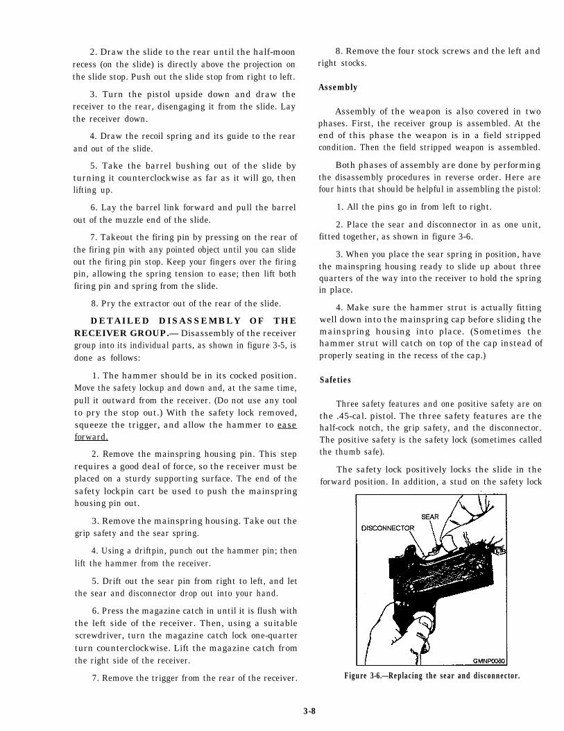
Figure 3-5.—Detailed receiver disassembly of the .45-cal. pistol.
3-7
2. Draw the slide to the rear until the half-moonrecess (on the slide) is directly above the projection onthe slide stop. Push out the slide stop from right to left.
3. Turn the pistol upside down and draw thereceiver to the rear, disengaging it from the slide. Laythe receiver down.
4. Draw the recoil spring and its guide to the rearand out of the slide.
5. Take the barrel bushing out of the slide byturning it counterclockwise as far as it will go, thenlifting up.
6. Lay the barrel link forward and pull the barrelout of the muzzle end of the slide.
7. Takeout the firing pin by pressing on the rear ofthe firing pin with any pointed object until you can slideout the firing pin stop. Keep your fingers over the firingpin, allowing the spring tension to ease; then lift bothfiring pin and spring from the slide.
8. Pry the extractor out of the rear of the slide.
DETAILED DISASSEMBLY OF THERECEIVER GROUP.— Disassembly of the receivergroup into its individual parts, as shown in figure 3-5, isdone as follows:
1. The hammer should be in its cocked position.Move the safety lockup and down and, at the same time,pull it outward from the receiver. (Do not use any toolto pry the stop out.) With the safety lock removed,squeeze the trigger, and allow the hammer to easeforward.
2. Remove the mainspring housing pin. This steprequires a good deal of force, so the receiver must beplaced on a sturdy supporting surface. The end of thesafety lockpin cart be used to push the mainspringhousing pin out.
3. Remove the mainspring housing. Take out thegrip safety and the sear spring.
4. Using a driftpin, punch out the hammer pin; thenlift the hammer from the receiver.
5. Drift out the sear pin from right to left, and letthe sear and disconnector drop out into your hand.
6. Press the magazine catch in until it is flush withthe left side of the receiver. Then, using a suitablescrewdriver, turn the magazine catch lock one-quarterturn counterclockwise. Lift the magazine catch fromthe right side of the receiver.
7. Remove the trigger from the rear of the receiver.
8. Remove the four stock screws and the left andright stocks.
Assembly
Assembly of the weapon is also covered in twophases. First, the receiver group is assembled. At theend of this phase the weapon is in a field strippedcondition. Then the field stripped weapon is assembled.
Both phases of assembly are done by performingthe disassembly procedures in reverse order. Here arefour hints that should be helpful in assembling the pistol:
1. All the pins go in from left to right.
2. Place the sear and disconnector in as one unit,fitted together, as shown in figure 3-6.
3. When you place the sear spring in position, havethe mainspring housing ready to slide up about threequarters of the way into the receiver to hold the springin place.
4. Make sure the hammer strut is actually fittingwell down into the mainspring cap before sliding themainspring housing into place. (Sometimes thehammer strut will catch on top of the cap instead ofproperly seating in the recess of the cap.)
Safeties
Three safety features and one positive safety are onthe .45-cal. pistol. The three safety features are thehalf-cock notch, the grip safety, and the disconnector.The positive safety is the safety lock (sometimes calledthe thumb safe).
The safety lock positively locks the slide in theforward position. In addition, a stud on the safety lock
Figure 3-6.—Replacing the sear and disconnector.
3-8
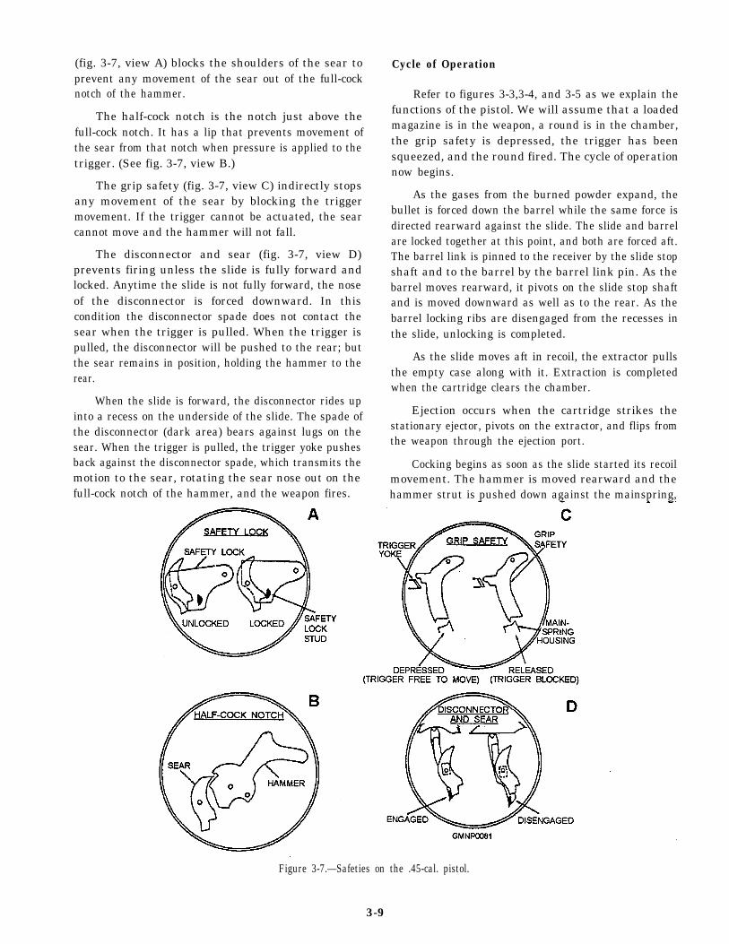
(fig. 3-7, view A) blocks the shoulders of the sear toprevent any movement of the sear out of the full-cocknotch of the hammer.
The half-cock notch is the notch just above thefull-cock notch. It has a lip that prevents movement ofthe sear from that notch when pressure is applied to thetrigger. (See fig. 3-7, view B.)
The grip safety (fig. 3-7, view C) indirectly stopsany movement of the sear by blocking the triggermovement. If the trigger cannot be actuated, the searcannot move and the hammer will not fall.
The disconnector and sear (fig. 3-7, view D)prevents firing unless the slide is fully forward andlocked. Anytime the slide is not fully forward, the noseof the disconnector is forced downward. In thiscondition the disconnector spade does not contact thesear when the trigger is pulled. When the trigger ispulled, the disconnector will be pushed to the rear; butthe sear remains in position, holding the hammer to therear.
When the slide is forward, the disconnector rides upinto a recess on the underside of the slide. The spade ofthe disconnector (dark area) bears against lugs on thesear. When the trigger is pulled, the trigger yoke pushesback against the disconnector spade, which transmits themotion to the sear, rotating the sear nose out on thefull-cock notch of the hammer, and the weapon fires.
Cycle of Operation
Refer to figures 3-3,3-4, and 3-5 as we explain thefunctions of the pistol. We will assume that a loadedmagazine is in the weapon, a round is in the chamber,the grip safety is depressed, the trigger has beensqueezed, and the round fired. The cycle of operationnow begins.
As the gases from the burned powder expand, thebullet is forced down the barrel while the same force isdirected rearward against the slide. The slide and barrelare locked together at this point, and both are forced aft.The barrel link is pinned to the receiver by the slide stopshaft and to the barrel by the barrel link pin. As thebarrel moves rearward, it pivots on the slide stop shaftand is moved downward as well as to the rear. As thebarrel locking ribs are disengaged from the recesses inthe slide, unlocking is completed.
As the slide moves aft in recoil, the extractor pullsthe empty case along with it. Extraction is completedwhen the cartridge clears the chamber.
Ejection occurs when the cartridge strikes thestationary ejector, pivots on the extractor, and flips fromthe weapon through the ejection port.
Cocking begins as soon as the slide started its recoilmovement. The hammer is moved rearward and thehammer strut is pushed down against the mainspring,
Figure 3-7.—Safeties on the .45-cal. pistol.
3-9
compressing it. When the slide strikes the recoil springguide collar, its rearward movement is stopped. Therecoil spring then causes the slide to begin its forwardmovement. The hammer follows the slide for a shortdistance. Then the sear, which bears against the hammerthrough the action of the sear spring, enters the full-cocknotch of the hammer and holds it in a cocked position.Feeding starts as soon as the slide, moving to the rear,clears the top of the magazine. The magazine follower,under pressure from the magazine spring, forces the topround against the lips of the magazine. This places thetop cartridge in position to be picked up by the face ofthe slide during its forward movement.
Cambering occurs when the forward moving slidepushes a new round into the chamber. As the bullet ispushed up the ramp into the chamber, the base of thecartridge slides up the face of the slide. As this happensthe groove on the base of the cartridge is engaged by thehooked extractor.
After cambering, the slide continues forward asmall distance, pushing the barrel ahead of it. As thebarrel moves, it pivots up and forward on the barrel link.The locking ribs on the barrel enter the locking recessesin the slide, thereby locking the two together.
Firing will start the cycle all over again. When thegrip safety is depressed and the trigger is squeezed, thetrigger yoke presses against the disconnector, whichpushes aft on the sear. The sear rotates on its pin,disengaging from the notch on the hammer. The
The M9 pistol has a short recoil system, using afalling locking block. The pressure delveloped by theexpanding gases of a fired round recoils the slide andbarrel assembly. After a short distance, the lockingblock is disengaged from the slide, the barrrel stopsagainst the frame, and the slide continues its rearwardmainspring pushes up on the hammers strut, roataing the
hammer forward. The hammer strikes the firing pinwhich, in turn, strikes the cartridge primer.
For more information on the M1911A1 .45-cal.pistol, refer to U.S. Army TM 9-1005-211-12.
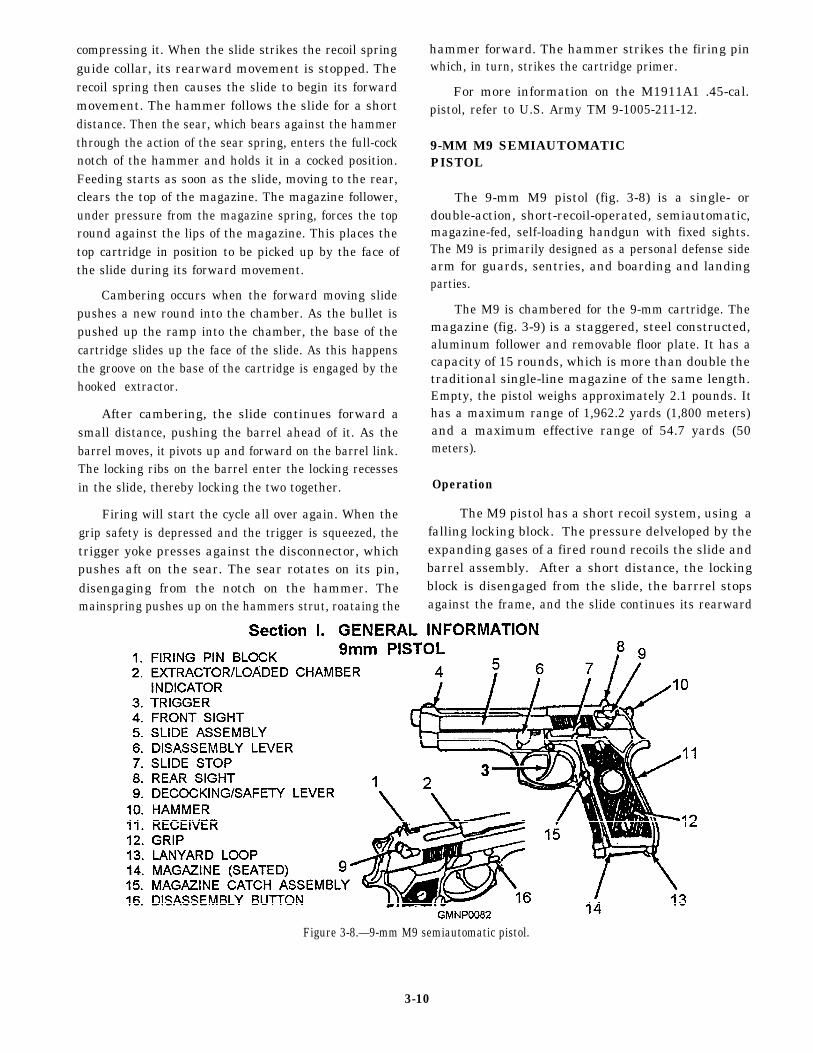
9-MM M9 SEMIAUTOMATICPISTOL
The 9-mm M9 pistol (fig. 3-8) is a single- ordouble-action, short-recoil-operated, semiautomatic,magazine-fed, self-loading handgun with fixed sights.The M9 is primarily designed as a personal defense sidearm for guards, sentries, and boarding and landingparties.
The M9 is chambered for the 9-mm cartridge. Themagazine (fig. 3-9) is a staggered, steel constructed,aluminum follower and removable floor plate. It has acapacity of 15 rounds, which is more than double thetraditional single-line magazine of the same length.Empty, the pistol weighs approximately 2.1 pounds. Ithas a maximum range of 1,962.2 yards (1,800 meters)and a maximum effective range of 54.7 yards (50meters).
Operation
Figure 3-8.—9-mm M9 semiautomatic pistol.
3-10
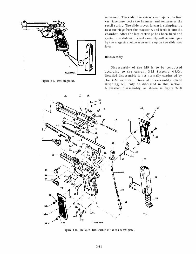
Figure 3-9.—M9) magazine.
movement. The slide then extracts and ejects the firedcartridge case, cocks the hammer, and compresses therecoil spring. The slide moves forward, stripping thenext cartridge from the magazine, and feeds it into thechamber. After the last cartridge has been fired andejected, the slide and barrel assembly will remain openby the magazine follower pressing up on the slide stoplever.
Disassembly
Disassembly of the M9 is to be conductedaccording to the current 3-M Systems MRCs.Detailed disassembly is not normally conducted bythe GM armorer. General disassembly (fieldstripping) will only be discussed in this section.A detailed disassembly, as shown in figure 3-10
Figure 3-10.—Detailed disassembly of the 9-mm M9 pistol.
3-11

Table 3-1.—Part Number Nomenclature
Part # Nomenclature Part # Nomenclature
1 Barrel (Factory Fitting Required) 34 Ejector Spring Pin
2 Locking Block 35 Hammer
3 Locking Block Plunger 36 Hammer Pin
4 Locking Block Plunger – Retaining Pin 37 Hammer Spring Guide
5 Slide (Factory Fitting Required) 38 Hammer Spring
6 Extractor 39 Hammer Spring Cap
7 Extractor Pin 40 Sear
8 Extractor Spring 41 Sear Spring
9 Rear Sight (Fitting Required) 42 Sear Pin
10 Trigger Bar Release Plunger 43 Magazine Release
11 Trigger Bar Release Plunger Spring 46 Magazine ReleaseButton Spring
12 Firing Pin 47 Hammer Spring Cap Pin
13 Firing Pin Spring 48/49P Grips (Plast i c ) Pair
14 Safety 48/49W Grips (Wood) Pair
15 Firing Pin Plunger 50 Grip Screw
18 Recoil Spring 51 Grip Bush
19 Recoil Spring Guide 52 Magazine Box
20 Frame 53 Magazine Follower
21 Disassembling Latch 54 Magazine Bottom
22 Slide Catch Spring 55 Magazine Spring
23 Slide Catch 56 Magazine Lock Plate
24 Trigger 57 Firing Pin CatchSpring
25 Trigger Pin 58 Firing Pin Catch
26 Trigger Spring 59 Firing Pin CatchRetaining Spring Pin
27 Trigger Bar 60 Safety Plunger Spring
28 Trigger Bar Spring 61 Safety Plunger
29 Disassembling Latch Release Button 62 Right Safety Lever
30 Disassembling Latch Release Button 63 Right Safety LeverSpring Pin
31 Hammer Release Lever 64 Firing Pin Catch Lever
32 Ejector 65 Magazine Catch SpringBush (Short)
33 Hammer Release Lever Pin 66 Magazine Catch SpringBush (Long)
69 Spring Washer
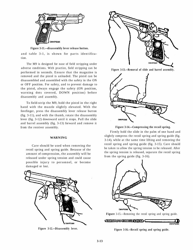
Figure 3-11.—disassembly lever release button.
and table 3-1, is shown for parts identifica-tion.
The M9 is designed for ease of field stripping underadverse conditions. With practice, field stripping can beperformed in seconds. Ensure that the magazine isremoved and the pistol is unloaded. The pistol can bedisassembled and assembled with the safety in the ONor OFF position. For safety, and to prevent damage tothe pistol, always engage the safety (ON position,warning dots covered, DOWN position) beforedisassembly and assembly.
To field-strip the M9, hold the pistol in the righthand with the muzzle slightly elevated. With theforefinger, press the disassembly lever release button(fig. 3-11), and with the thumb, rotate the disassemblylever (fig. 3-12) downward until it stops. Pull the slideand barrel assembly (fig. 3-13) forward and remove itfrom the receiver assembly. Figure 3-14.—Compressing the recoil spring.
WARNING
Care should be used when removing therecoil spring and spring guide. Because of theamount of compression, the assembly will bereleased under spring tension and could causepossible injury to personnel, or becomedamaged or lost.
Figure 3-12.—Disassembly lever.
Figure 3-13.—Removal of slide and barrel assembly.
Firmly hold the slide in the palm of one hand andslightly compress the recoil spring and spring guide (fig.3-14), while at the same time lifting and removing therecoil spring and spring guide (fig. 3-15). Care shouldbe taken to allow the spring tension to be released. Afterthe spring tension is released, separate the recoil springfrom the spring guide (fig. 3-16).
Figure 3-15.—Removing the recoil spring and spring guide.
Figure 3-16.—RecoiI spring and spring guide.
3-13
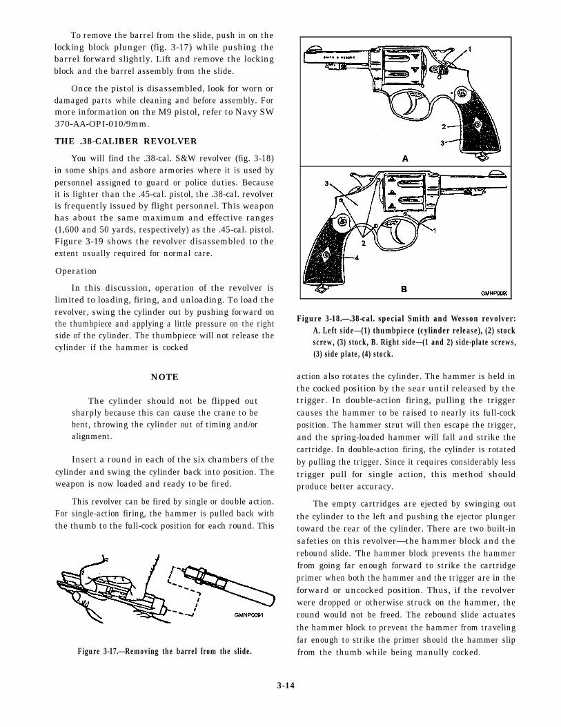
To remove the barrel from the slide, push in on thelocking block plunger (fig. 3-17) while pushing thebarrel forward slightly. Lift and remove the lockingblock and the barrel assembly from the slide.
Once the pistol is disassembled, look for worn ordamaged parts while cleaning and before assembly. Formore information on the M9 pistol, refer to Navy SW370-AA-OPI-010/9mm.
THE .38-CALIBER REVOLVER
You will find the .38-cal. S&W revolver (fig. 3-18)in some ships and ashore armories where it is used bypersonnel assigned to guard or police duties. Becauseit is lighter than the .45-cal. pistol, the .38-cal. revolveris frequently issued by flight personnel. This weaponhas about the same maximum and effective ranges(1,600 and 50 yards, respectively) as the .45-cal. pistol.Figure 3-19 shows the revolver disassembled to theextent usually required for normal care.
Operation
In this discussion, operation of the revolver islimited to loading, firing, and unloading. To load therevolver, swing the cylinder out by pushing forward onthe thumbpiece and applying a little pressure on the rightside of the cylinder. The thumbpiece will not release thecylinder if the hammer is cocked
NOTE
The cylinder should not be flipped outsharply because this can cause the crane to bebent, throwing the cylinder out of timing and/oralignment.
Insert a round in each of the six chambers of thecylinder and swing the cylinder back into position. Theweapon is now loaded and ready to be fired.
This revolver can be fired by single or double action.For single-action firing, the hammer is pulled back withthe thumb to the full-cock position for each round. This
Figure 3-17.—Removing the barrel from the slide.
Figure 3-18.—.38-cal. special Smith and Wesson revolver:A. Left side—(1) thumbpiece (cylinder release), (2) stockscrew, (3) stock, B. Right side—(1 and 2) side-plate screws,(3) side plate, (4) stock.
action also rotates the cylinder. The hammer is held inthe cocked position by the sear until released by thetrigger. In double-action firing, pulling the triggercauses the hammer to be raised to nearly its full-cockposition. The hammer strut will then escape the trigger,and the spring-loaded hammer will fall and strike thecartridge. In double-action firing, the cylinder is rotatedby pulling the trigger. Since it requires considerably lesstrigger pull for single action, this method shouldproduce better accuracy.
The empty cartridges are ejected by swinging outthe cylinder to the left and pushing the ejector plungertoward the rear of the cylinder. There are two built-insafeties on this revolver—the hammer block and therebound slide. ‘The hammer block prevents the hammerfrom going far enough forward to strike the cartridgeprimer when both the hammer and the trigger are in theforward or uncocked position. Thus, if the revolverwere dropped or otherwise struck on the hammer, theround would not be freed. The rebound slide actuatesthe hammer block to prevent the hammer from travelingfar enough to strike the primer should the hammer slipfrom the thumb while being manully cocked.
3-14
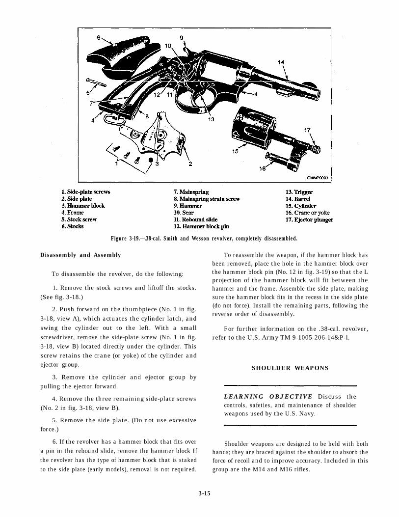
Figure 3-19.—.38-cal. Smith and Wesson revolver, completely disassembled.
Disassembly and Assembly
To disassemble the revolver, do the following:
1. Remove the stock screws and liftoff the stocks.(See fig. 3-18.)
2. Push forward on the thumbpiece (No. 1 in fig.3-18, view A), which actuates the cylinder latch, andswing the cylinder out to the left. With a smallscrewdriver, remove the side-plate screw (No. 1 in fig.3-18, view B) located directly under the cylinder. Thisscrew retains the crane (or yoke) of the cylinder andejector group.
3. Remove the cylinder and ejector group bypulling the ejector forward.
4. Remove the three remaining side-plate screws(No. 2 in fig. 3-18, view B).
5. Remove the side plate. (Do not use excessiveforce.)
6. If the revolver has a hammer block that fits overa pin in the rebound slide, remove the hammer block Ifthe revolver has the type of hammer block that is stakedto the side plate (early models), removal is not required.
To reassemble the weapon, if the hammer block hasbeen removed, place the hole in the hammer block overthe hammer block pin (No. 12 in fig. 3-19) so that the Lprojection of the hammer block will fit between thehammer and the frame. Assemble the side plate, makingsure the hammer block fits in the recess in the side plate(do not force). Install the remaining parts, following thereverse order of disassembly.
For further information on the .38-cal. revolver,refer to the U.S. Army TM 9-1005-206-14&P-l.
SHOULDER WEAPONS
LEARNING OBJECTIVE Discuss thecontrols, safeties, and maintenance of shoulderweapons used by the U.S. Navy.
Shoulder weapons are designed to be held with bothhands; they are braced against the shoulder to absorb theforce of recoil and to improve accuracy. Included in thisgroup are the M14 and M16 rifles.
3-15
M14 RIFLE
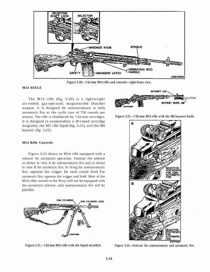
The M14 rifle (fig. 3-20) is a lightweight
Figure 3-20.—7.62-mm M14 rifle and controls—right-front view.
air-cooled, gas-operated, magazine-fed shoulderweapon. It is designed for semiautomatic or fullyautomatic fire at the cyclic rate of 750 rounds perminute. The rifle is chambered for 7.62-mm cartridges.It is designed to accommodate a 20-round cartridgemagazine, the M2 rifle bipod (fig. 3-21), and the M6bayonet (fig. 3-22).
M14 Rifle Controls
Figure 3-23 shows an M14 rifle equipped with aselector for automatic operation. Position the selectoras shown in view A for semiautomatic fire and as shownin view B for automatic fire. In firing for semiautomaticfire, squeeze the trigger for each round fired Forautomatic fire, squeeze the trigger and hold. Most of theM14 rifles issued to the Navy will not be equipped withthe automatic selector, only semiautomatic fire will bepossible.
Figure 3-22.—7.62-mm M14 rifle with the M6 bayonet knife.
Figure 3-21.—7.62-mm M14 rifle with the bipod installed. Figure 3-23.—Selector for semiautomatic and automatic fire.
3-16
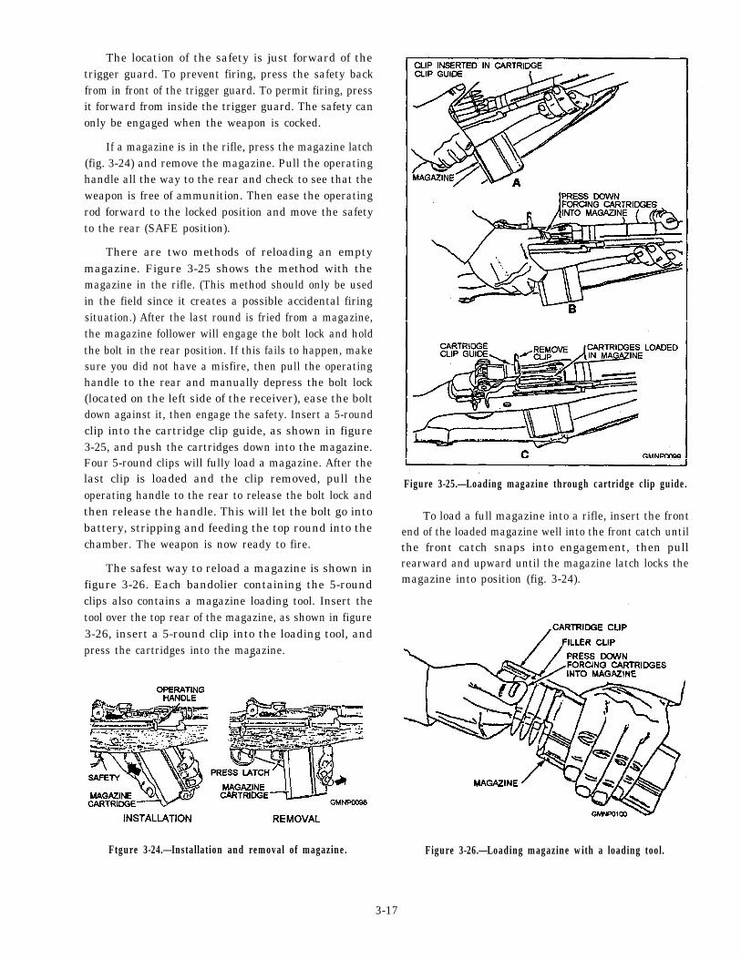
The location of the safety is just forward of thetrigger guard. To prevent firing, press the safety backfrom in front of the trigger guard. To permit firing, pressit forward from inside the trigger guard. The safety canonly be engaged when the weapon is cocked.
If a magazine is in the rifle, press the magazine latch(fig. 3-24) and remove the magazine. Pull the operatinghandle all the way to the rear and check to see that theweapon is free of ammunition. Then ease the operatingrod forward to the locked position and move the safetyto the rear (SAFE position).
There are two methods of reloading an emptymagazine. Figure 3-25 shows the method with themagazine in the rifle. (This method should only be usedin the field since it creates a possible accidental firingsituation.) After the last round is fried from a magazine,the magazine follower will engage the bolt lock and holdthe bolt in the rear position. If this fails to happen, makesure you did not have a misfire, then pull the operatinghandle to the rear and manually depress the bolt lock(located on the left side of the receiver), ease the boltdown against it, then engage the safety. Insert a 5-roundclip into the cartridge clip guide, as shown in figure3-25, and push the cartridges down into the magazine.Four 5-round clips will fully load a magazine. After thelast clip is loaded and the clip removed, pull theoperating handle to the rear to release the bolt lock andthen release the handle. This will let the bolt go intobattery, stripping and feeding the top round into thechamber. The weapon is now ready to fire.
The safest way to reload a magazine is shown infigure 3-26. Each bandolier containing the 5-roundclips also contains a magazine loading tool. Insert thetool over the top rear of the magazine, as shown in figure3-26, insert a 5-round clip into the loading tool, andpress the cartridges into the magazine.
Ftgure 3-24.—Installation and removal of magazine.
Figure 3-25.—Loading magazine through cartridge clip guide.
To load a full magazine into a rifle, insert the frontend of the loaded magazine well into the front catch untilthe front catch snaps into engagement, then pullrearward and upward until the magazine latch locks themagazine into position (fig. 3-24).
Figure 3-26.—Loading magazine with a loading tool.
3-17
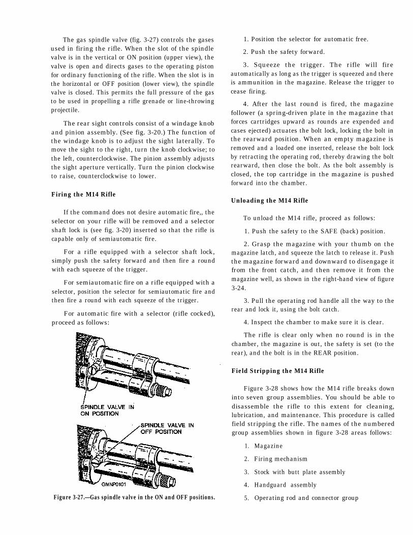
The gas spindle valve (fig. 3-27) controls the gasesused in firing the rifle. When the slot of the spindlevalve is in the vertical or ON position (upper view), thevalve is open and directs gases to the operating pistonfor ordinary functioning of the rifle. When the slot is inthe horizontal or OFF position (lower view), the spindlevalve is closed. This permits the full pressure of the gasto be used in propelling a rifle grenade or line-throwingprojectile.
The rear sight controls consist of a windage knoband pinion assembly. (See fig. 3-20.) The function ofthe windage knob is to adjust the sight laterally. Tomove the sight to the right, turn the knob clockwise; tothe left, counterclockwise. The pinion assembly adjuststhe sight aperture vertically. Turn the pinion clockwiseto raise, counterclockwise to lower.
Firing the M14 Rifle
If the command does not desire automatic fire,, theselector on your rifle will be removed and a selectorshaft lock is (see fig. 3-20) inserted so that the rifle iscapable only of semiautomatic fire.
For a rifle equipped with a selector shaft lock,simply push the safety forward and then fire a roundwith each squeeze of the trigger.
For semiautomatic fire on a rifle equipped with aselector, position the selector for semiautomatic fire andthen fire a round with each squeeze of the trigger.
For automatic fire with a selector (rifle cocked),proceed as follows:
Figure 3-27.—Gas spindle valve in the ON and OFF positions.
1. Position the selector for automatic free.
2. Push the safety forward.
3. Squeeze the trigger. The rifle will fireautomatically as long as the trigger is squeezed and thereis ammunition in the magazine. Release the trigger tocease firing.
4. After the last round is fired, the magazinefollower (a spring-driven plate in the magazine thatforces cartridges upward as rounds are expended andcases ejected) actuates the bolt lock, locking the bolt inthe rearward position. When an empty magazine isremoved and a loaded one inserted, release the bolt lockby retracting the operating rod, thereby drawing the boltrearward, then close the bolt. As the bolt assembly isclosed, the top cartridge in the magazine is pushedforward into the chamber.
Unloading the M14 Rifle
To unload the M14 rifle, proceed as follows:
1. Push the safety to the SAFE (back) position.
2. Grasp the magazine with your thumb on themagazine latch, and squeeze the latch to release it. Pushthe magazine forward and downward to disengage itfrom the front catch, and then remove it from themagazine well, as shown in the right-hand view of figure3-24.
3. Pull the operating rod handle all the way to therear and lock it, using the bolt catch.
4. Inspect the chamber to make sure it is clear.
The rifle is clear only when no round is in thechamber, the magazine is out, the safety is set (to therear), and the bolt is in the REAR position.
Field Stripping the M14 Rifle
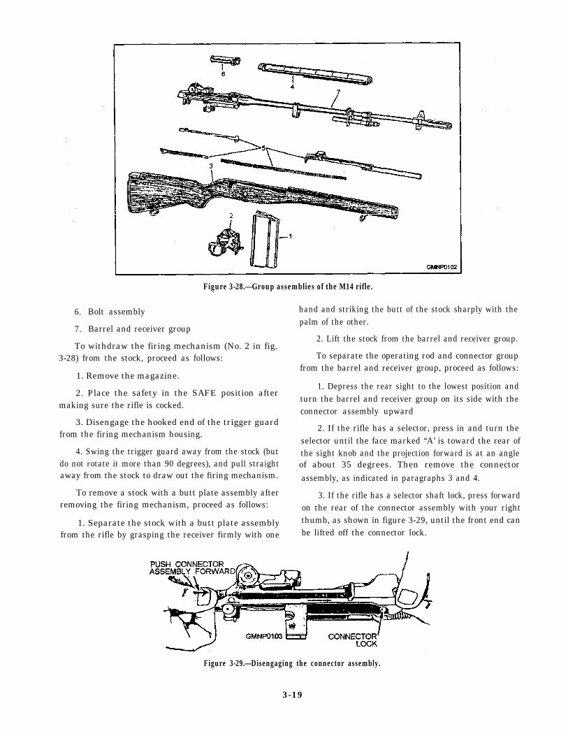
Figure 3-28 shows how the M14 rifle breaks downinto seven group assemblies. You should be able todisassemble the rifle to this extent for cleaning,lubrication, and maintenance. This procedure is calledfield stripping the rifle. The names of the numberedgroup assemblies shown in figure 3-28 areas follows:
1.
2.
3.
4.
5.
Magazine
Firing mechanism
Stock with butt plate assembly
Handguard assembly
Operating rod and connector group
6.
7.
Bolt assembly
Barrel and receiver group
Figure 3-28.—Group assemblies of the M14 rifle.
To withdraw the firing mechanism (No. 2 in fig.3-28) from the stock, proceed as follows:
1. Remove the magazine.
2. Place the safety in the SAFE position aftermaking sure the rifle is cocked.
3. Disengage the hooked end of the trigger guardfrom the firing mechanism housing.
4. Swing the trigger guard away from the stock (butdo not rotate it more than 90 degrees), and pull straightaway from the stock to draw out the firing mechanism.
To remove a stock with a butt plate assembly afterremoving the firing mechanism, proceed as follows:
1. Separate the stock with a butt plate assemblyfrom the rifle by grasping the receiver firmly with one
hand and striking the butt of the stock sharply with thepalm of the other.
2. Lift the stock from the barrel and receiver group.
To separate the operating rod and connector groupfrom the barrel and receiver group, proceed as follows:
1. Depress the rear sight to the lowest position andturn the barrel and receiver group on its side with theconnector assembly upward
2. If the rifle has a selector, press in and turn theselector until the face marked “A’ is toward the rear ofthe sight knob and the projection forward is at an angleof about 35 degrees. Then remove the connectorassembly, as indicated in paragraphs 3 and 4.
3. If the rifle has a selector shaft lock, press forwardon the rear of the connector assembly with your rightthumb, as shown in figure 3-29, until the front end canbe lifted off the connector lock.
Figure 3-29.—Disengaging the connector assembly.
3-19
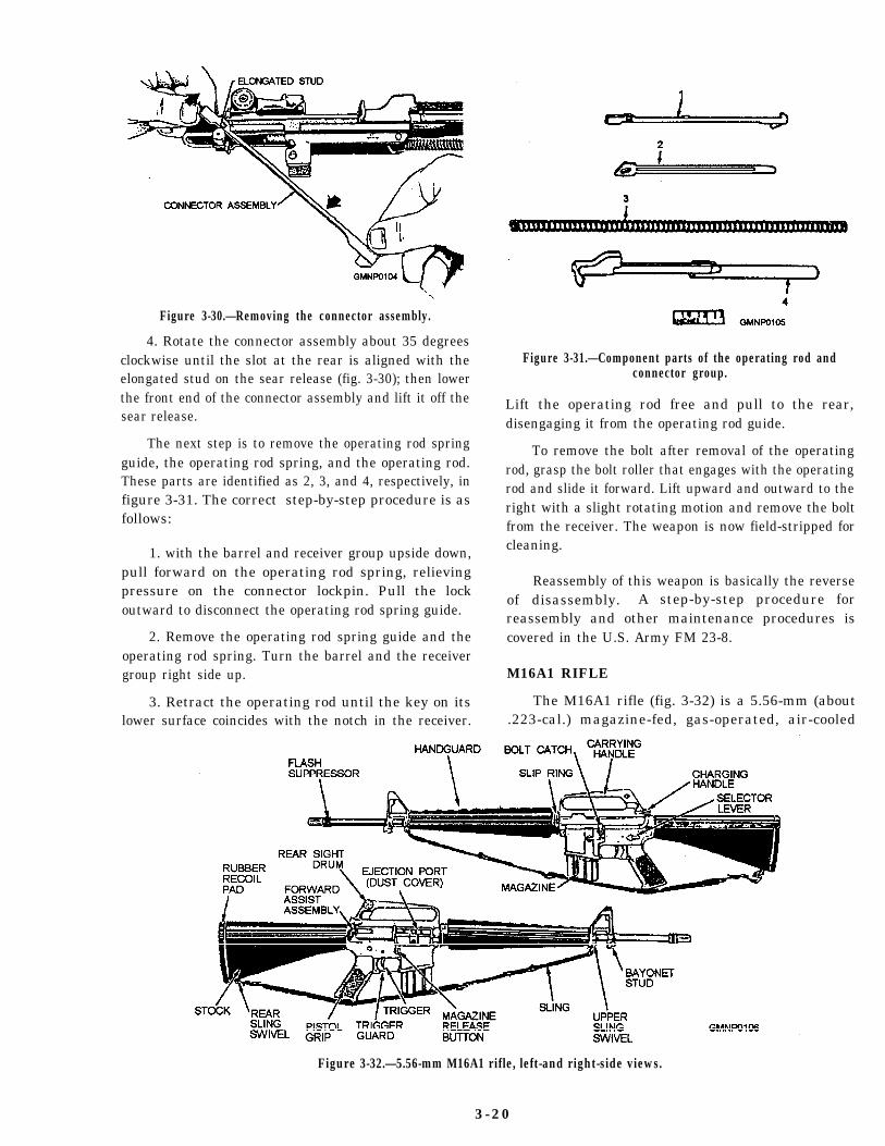
Figure 3-30.—Removing the connector assembly.
4. Rotate the connector assembly about 35 degreesclockwise until the slot at the rear is aligned with theelongated stud on the sear release (fig. 3-30); then lowerthe front end of the connector assembly and lift it off thesear release.
The next step is to remove the operating rod springguide, the operating rod spring, and the operating rod.These parts are identified as 2, 3, and 4, respectively, infigure 3-31. The correct step-by-step procedure is asfollows:
1. with the barrel and receiver group upside down,pull forward on the operating rod spring, relievingpressure on the connector lockpin. Pull the lockoutward to disconnect the operating rod spring guide.
2. Remove the operating rod spring guide and theoperating rod spring. Turn the barrel and the receivergroup right side up.
3. Retract the operating rod until the key on itslower surface coincides with the notch in the receiver.
Figure 3-31.—Component parts of the operating rod andconnector group.
Lift the operating rod free and pull to the rear,disengaging it from the operating rod guide.
To remove the bolt after removal of the operatingrod, grasp the bolt roller that engages with the operatingrod and slide it forward. Lift upward and outward to theright with a slight rotating motion and remove the boltfrom the receiver. The weapon is now field-stripped forcleaning.
Reassembly of this weapon is basically the reverseof disassembly. A step-by-step procedure forreassembly and other maintenance procedures iscovered in the U.S. Army FM 23-8.
M16A1 RIFLE
The M16A1 rifle (fig. 3-32) is a 5.56-mm (about.223-cal.) magazine-fed, gas-operated, air-cooled
Figure 3-32.—5.56-mm M16A1 rifle, left-and right-side views.
3 -20
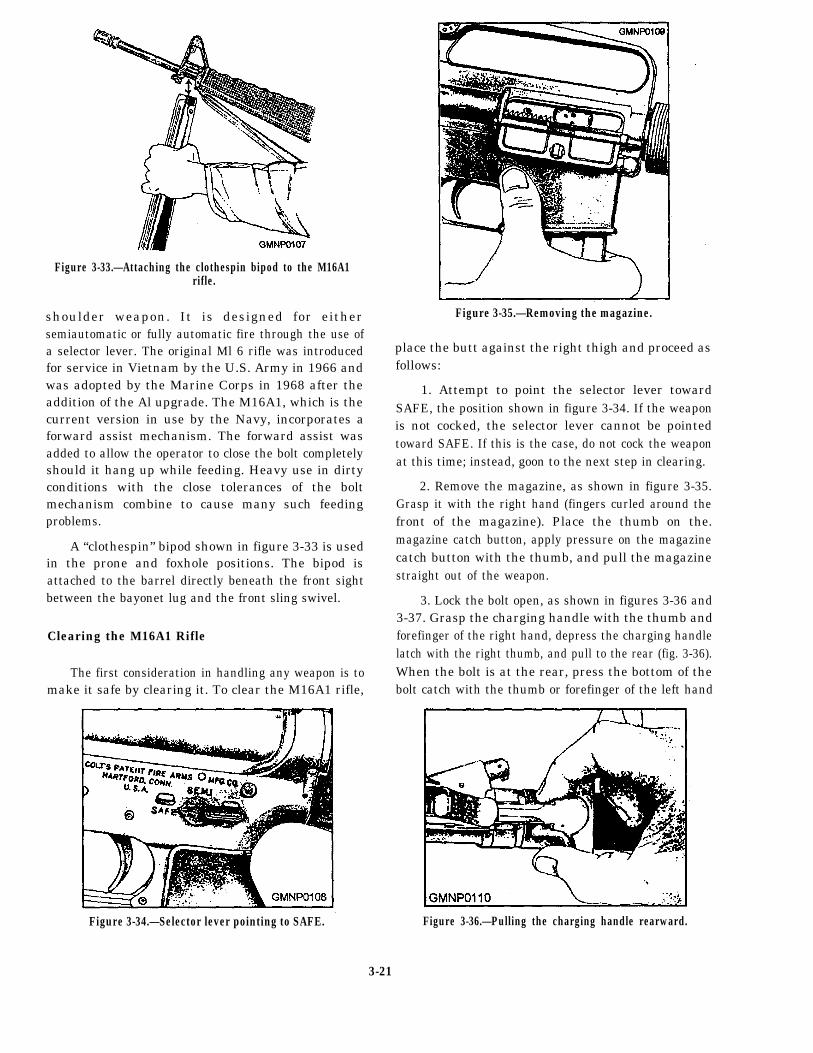
Figure 3-33.—Attaching the clothespin bipod to the M16A1rifle.
shoulder weapon. It is designed for eithersemiautomatic or fully automatic fire through the use ofa selector lever. The original Ml 6 rifle was introducedfor service in Vietnam by the U.S. Army in 1966 andwas adopted by the Marine Corps in 1968 after theaddition of the Al upgrade. The M16A1, which is thecurrent version in use by the Navy, incorporates aforward assist mechanism. The forward assist wasadded to allow the operator to close the bolt completelyshould it hang up while feeding. Heavy use in dirtyconditions with the close tolerances of the boltmechanism combine to cause many such feedingproblems.
A “clothespin” bipod shown in figure 3-33 is usedin the prone and foxhole positions. The bipod isattached to the barrel directly beneath the front sightbetween the bayonet lug and the front sling swivel.
Clearing the M16A1 Rifle
The first consideration in handling any weapon is tomake it safe by clearing it. To clear the M16A1 rifle,
Figure 3-34.—Selector lever pointing to SAFE.
Figure 3-35.—Removing the magazine.
place the butt against the right thigh and proceed asfollows:
1. Attempt to point the selector lever towardSAFE, the position shown in figure 3-34. If the weaponis not cocked, the selector lever cannot be pointedtoward SAFE. If this is the case, do not cock the weaponat this time; instead, goon to the next step in clearing.
2. Remove the magazine, as shown in figure 3-35.Grasp it with the right hand (fingers curled around thefront of the magazine). Place the thumb on the.magazine catch button, apply pressure on the magazinecatch button with the thumb, and pull the magazinestraight out of the weapon.
3. Lock the bolt open, as shown in figures 3-36 and3-37. Grasp the charging handle with the thumb andforefinger of the right hand, depress the charging handlelatch with the right thumb, and pull to the rear (fig. 3-36).When the bolt is at the rear, press the bottom of thebolt catch with the thumb or forefinger of the left hand
Figure 3-36.—Pulling the charging handle rearward.
3-21
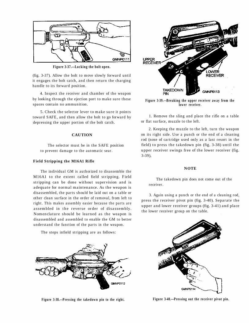
Figure 3-37.—Locking the bolt open.
(fig. 3-37). Allow the bolt to move slowly forward untilit engages the bolt catch, and then return the charginghandle to its forward position.
4. Inspect the receiver and chamber of the weaponby looking through the ejection port to make sure thesespaces contain no ammunition.
5. Check the selector lever to make sure it pointstoward SAFE, and then allow the bolt to go forward bydepressing the upper portion of the bolt catch.
CAUTION
The selector must be in the SAFE positionto prevent damage to the automatic sear.
Field Stripping the M16A1 Rifle
The individual GM is authorized to disassemble theM16A1 to the extent called field stripping. Fieldstripping can be done without supervision and isadequate for normal maintenance. As the weapon isdisassembled, the parts should be laid out on a table orother clean surface in the order of removal, from left toright. This makes assembly easier because the parts areassembled in the reverse order of disassembly.Nomenclature should be learned as the weapon isdisassembled and assembled to enable the GM to betterunderstand the function of the parts in the weapon.
Figure 3-39.—Breaking the upper receiver away from thelower receiver.
1. Remove the sling and place the rifle on a tableor flat surface, muzzle to the left.
2. Keeping the muzzle to the left, turn the weaponon its right side. Use a punch or the end of a cleaningrod (nose of cartridge used only as a last resort in thefield) to press the takedown pin (fig. 3-38) until theupper receiver swings free of the lower receiver (fig.3-39),
NOTE
The takedown pin does not come out of thereceiver.
3. Again using a punch or the end of a cleaning rod,press the receiver pivot pin (fig. 3-40). Separate theupper and lower receiver groups (fig. 3-41) and placethe lower receiver group on the table.
The steps infield stripping are as follows:
Figure 3-38.—Pressing the takedown pin to the right. Figure 3-40.—Pressing out the receiver pivot pin.
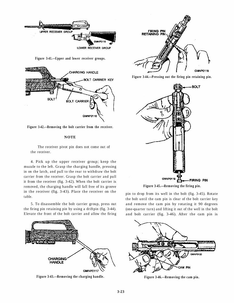
Figure 3-41.—Upper and lower receiver groups.
Figure 3-42.—Removing the bolt carrier from the receiver.
NOTE
The receiver pivot pin does not come out ofthe receiver.
4. Pick up the upper receiver group; keep themuzzle to the left. Grasp the charging handle, pressingin on the latch, and pull to the rear to withdraw the boltcarrier from the receiver. Grasp the bolt carrier and pullit from the receiver (fig. 3-42). When the bolt carrier isremoved, the charging handle will fall free of its groovein the receiver (fig. 3-43). Place the receiver on thetable.
5. To disassemble the bolt carrier group, press outthe firing pin retaining pin by using a driftpin (fig. 3-44).Elevate the front of the bolt carrier and allow the firing
Figure 3-43.—Removing the charging handle.
Figure 3-44.—Pressing out the firing pin retaining pin.
Figure 3-45.—Removing the firing pin.
pin to drop from its well in the bolt (fig. 3-45). Rotatethe bolt until the cam pin is clear of the bolt carrier keyand remove the cam pin by rotating it 90 degrees(one-quarter turn) and lifting it out of the well in the boltand bolt carrier (fig. 3-46). After the cam pin is
Figure 3-46.—Removing the cam pin.
3-23
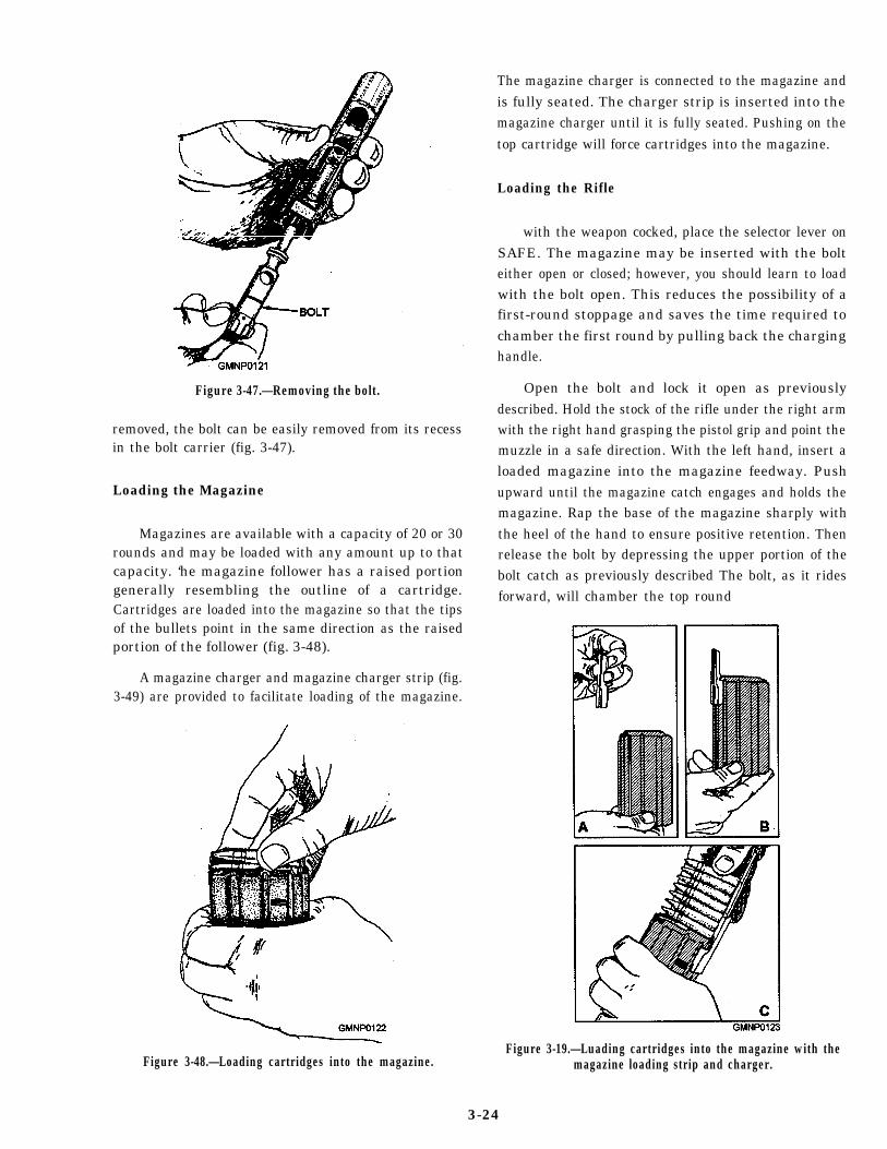
Figure 3-47.—Removing the bolt.
removed, the bolt can be easily removed from its recessin the bolt carrier (fig. 3-47).
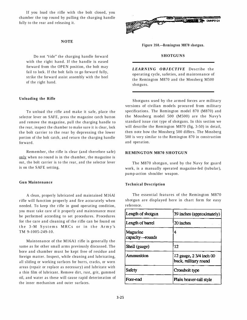
Loading the Magazine
Magazines are available with a capacity of 20 or 30rounds and may be loaded with any amount up to thatcapacity. ‘he magazine follower has a raised portiongenerally resembling the outline of a cartridge.Cartridges are loaded into the magazine so that the tipsof the bullets point in the same direction as the raisedportion of the follower (fig. 3-48).
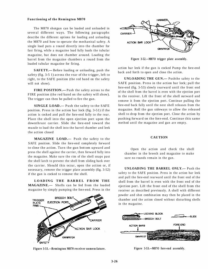
A magazine charger and magazine charger strip (fig.3-49) are provided to facilitate loading of the magazine.
Figure 3-48.—Loading cartridges into the magazine.
The magazine charger is connected to the magazine andis fully seated. The charger strip is inserted into themagazine charger until it is fully seated. Pushing on thetop cartridge will force cartridges into the magazine.
Loading the Rifle
with the weapon cocked, place the selector lever onSAFE. The magazine may be inserted with the bolteither open or closed; however, you should learn to loadwith the bolt open. This reduces the possibility of afirst-round stoppage and saves the time required tochamber the first round by pulling back the charginghandle.
Open the bolt and lock it open as previouslydescribed. Hold the stock of the rifle under the right armwith the right hand grasping the pistol grip and point themuzzle in a safe direction. With the left hand, insert aloaded magazine into the magazine feedway. Pushupward until the magazine catch engages and holds themagazine. Rap the base of the magazine sharply withthe heel of the hand to ensure positive retention. Thenrelease the bolt by depressing the upper portion of thebolt catch as previously described The bolt, as it ridesforward, will chamber the top round
Figure 3-19.—Luading cartridges into the magazine with themagazine loading strip and charger.
3-24
If you load the rifle with the bolt closed, youchamber the top round by pulling the charging handlefully to the rear and releasing it.
NOTE
Do not “ride” the charging handle forwardwith the right hand. If the handle is easedforward from the OPEN position, the bolt mayfail to lock. If the bolt fails to go forward fully,strike the forward assist assembly with the heelof the right hand.
Unloading the Rifle
To unload the rifle and make it safe, place theselector lever on SAFE, press the magazine catch buttonand remove the magazine, pull the charging handle tothe rear, inspect the chamber to make sure it is clear, lockthe bolt carrier to the rear by depressing the lowerportion of the bolt catch, and return the charging handleforward.
Remember, the rifle is clear (and therefore safe)only when no round is in the chamber, the magazine isout, the bolt carrier is to the rear, and the selector leveris on the SAFE setting.
Gun Maintenance
A clean, properly lubricated and maintained M16Alrifle will function properly and fire accurately whenneeded. To keep the rifle in good operating condition,you must take care of it properly and maintenance mustbe performed according to set procedures. Proceduresfor the care and cleaning of the rifle can be found onthe 3-M Systems MRCs or in the Army’sTM 9-1005-249-10.
Maintenance of the M16A1 rifle is generally thesame as for other small arms previously discussed. Thebore and chamber must be kept free of residue andforeign matter. Inspect, while cleaning and lubricating,all sliding or working surfaces for burrs, cracks, or wornareas (repair or replace as necessary) and lubricate witha thin film of lubricant. Remove dirt, rust, grit, gummedoil, and water as these will cause rapid deterioration ofthe inner mechanism and outer surfaces.
Figure 3S0.—Remington M870 shotgun.
SHOTGUNS
LEARNING OBJECTIVE Describe theoperating cycle, safeties, and maintenance ofthe Remington M870 and the Mossberg M500shotguns.
Shotguns used by the armed forces are militaryversions of civilian models procured from militaryspecifications. The Remington model 870 (M870) andthe Mossberg model 500 (M500) are the Navy’sstandard issue riot type of shotguns. In this section wewill describe the Remington M870 (fig, 3-50) in detail,then note how the Mossberg 500 differs. The Mossberg500 is very similar to the Remington 870 in constructionand operation.
REMINGTON M870 SHOTGUN
The M870 shotgun, used by the Navy for guardwork, is a manually operated magazine-fed (tubular),pump-action shoulder weapon.
Technical Description
The essential features of the Remington M870shotgun are displayed here in chart form for easyreference.
3-25
Functioning of the Remington M870
The M870 shotgun can be loaded and unloaded inseveral different ways. The following paragraphsdescribe the different options for loading and unloadingthe M870 and how to operate the mechanical safety. Asingle load puts a round directly into the chamber forfast firing, while a magazine load fully loads the tubularmagazine, but does not chamber around. Loading thebarrel from the magazine chambers a round from theloaded tubular magazine for firing.
SAFETY.— Before loading or unloading, push thesafety (fig. 3-5 1) across the rear of the trigger, left toright, to the SAFE position (the red band on the safetywill not show).
FIRE POSITION.— Push the safety across to theFIRE position (the red band on the safety will show).The trigger can then be pulled to fire the gun.
SINGLE LOAD.— Push the safety to the SAFEposition. Press in the action bar lock (fig. 3-51) if theaction is cocked and pull the fore-end fully to the rear.Place the shell into the open ejection port upon thedownthrust carrier. Slide the fore-end toward themuzzle to load the shell into the barrel chamber and leekthe action closed
MAGAZINE LOAD.— Push the safety to theSAFE position. Slide the fore-end completely forwardto close the action. Turn the gun bottom upward andpress the shell against the carrier, then forward fully intothe magazine. Make sure the rim of the shell snaps pastthe shell latch to prevent the shell from sliding back overthe carrier. Should this occur, open the action or, ifnecessary, remove the trigger plate assembly (fig. 3-52)if the gun is cocked to remove the shell.
LOADING THE BARREL FROM THEMAGAZINE.— Shells can be fed from the loadedmagazine by simply pumping the fore-end. Press in the
Figure 3-51.—Remington M870 receiver nomenclature.
Figure 3-52.—M87O trigger plate assembly.
action bar leek if the gun is cocked Pump the fore-endback and forth to open and close the action.
UNLOADING THE GUN.— Pushthe safety to theSAFE position. Press in the action bar lock; pull thefore-end (fig. 3-53) slowly rearward until the front endof the shell from the barrel is even with the ejection portin the receiver. Lift the front of the shell outward andremove it from the ejection port. Continue pulling thefore-end back fully until the next shell releases from themagazine. Roll the gun sideways to allow the releasedshell to drop from the ejection port. Close the action bypushing forward on the fore-end. Continue this samemethod until the magazine and gun are empty.
CAUTION
Open the action and check the shellchamber in the breech and magazine to makesure no rounds remain in the gun.
UNLOADING THE BARREL ONLY.— Push thesafety to the SAFE position. Press in the action bar leekand pull the fore-end rearward until the front end of theshell from the barrel is even with the front end of theejection port. Lift the front end of the shell from thereceiver as described previously. A shell with differentpowder and shot combination may then be placed in thechamber and the action closed without disturbing shellsin the magazine.
Figure 3-53.—M87O fore-end assembly.
3-26
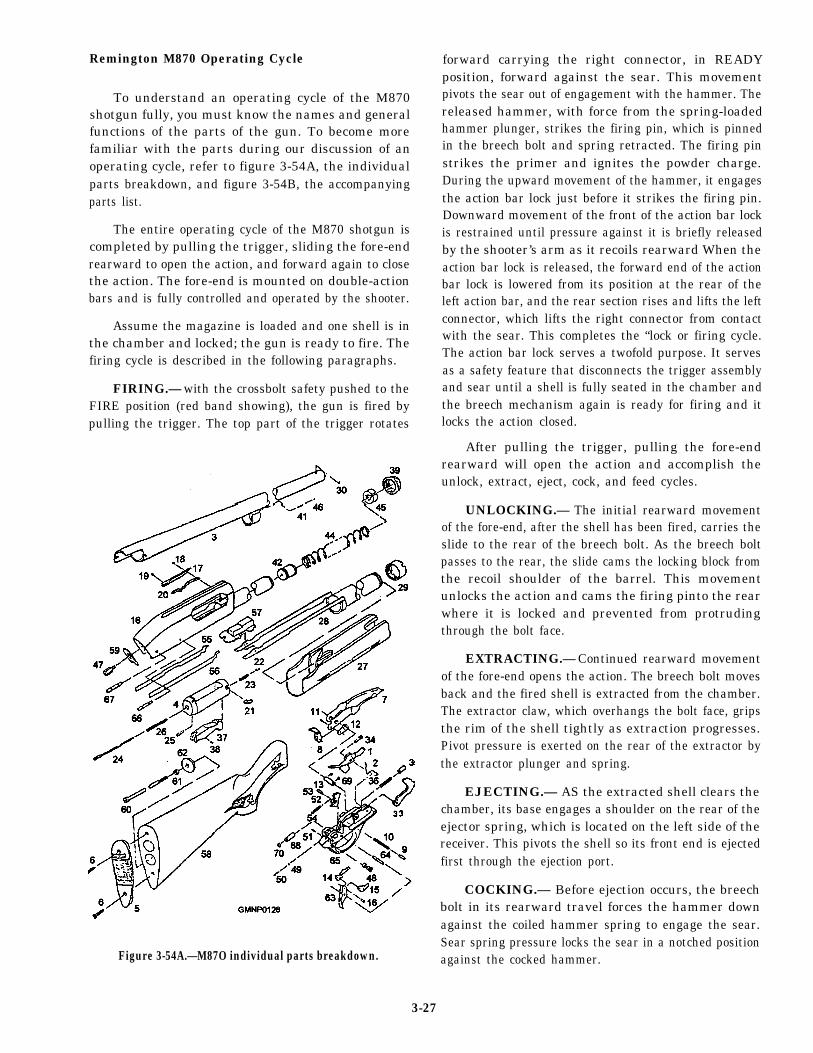
Remington M870 Operating Cycle
To understand an operating cycle of the M870shotgun fully, you must know the names and generalfunctions of the parts of the gun. To become morefamiliar with the parts during our discussion of anoperating cycle, refer to figure 3-54A, the individualparts breakdown, and figure 3-54B, the accompanyingparts list.
The entire operating cycle of the M870 shotgun iscompleted by pulling the trigger, sliding the fore-endrearward to open the action, and forward again to closethe action. The fore-end is mounted on double-actionbars and is fully controlled and operated by the shooter.
Assume the magazine is loaded and one shell is inthe chamber and locked; the gun is ready to fire. Thefiring cycle is described in the following paragraphs.
FIRING.— with the crossbolt safety pushed to theFIRE position (red band showing), the gun is fired bypulling the trigger. The top part of the trigger rotates
Figure 3-54A.—M87O individual parts breakdown.
forward carrying the right connector, in READYposition, forward against the sear. This movementpivots the sear out of engagement with the hammer. Thereleased hammer, with force from the spring-loadedhammer plunger, strikes the firing pin, which is pinnedin the breech bolt and spring retracted. The firing pinstrikes the primer and ignites the powder charge.During the upward movement of the hammer, it engagesthe action bar lock just before it strikes the firing pin.Downward movement of the front of the action bar lockis restrained until pressure against it is briefly releasedby the shooter’s arm as it recoils rearward When theaction bar lock is released, the forward end of the actionbar lock is lowered from its position at the rear of theleft action bar, and the rear section rises and lifts the leftconnector, which lifts the right connector from contactwith the sear. This completes the “lock or firing cycle.The action bar lock serves a twofold purpose. It servesas a safety feature that disconnects the trigger assemblyand sear until a shell is fully seated in the chamber andthe breech mechanism again is ready for firing and itlocks the action closed.
After pulling the trigger, pulling the fore-endrearward will open the action and accomplish theunlock, extract, eject, cock, and feed cycles.
UNLOCKING.— The initial rearward movementof the fore-end, after the shell has been fired, carries theslide to the rear of the breech bolt. As the breech boltpasses to the rear, the slide cams the locking block fromthe recoil shoulder of the barrel. This movementunlocks the action and cams the firing pinto the rearwhere it is locked and prevented from protrudingthrough the bolt face.
EXTRACTING.— Continued rearward movementof the fore-end opens the action. The breech bolt movesback and the fired shell is extracted from the chamber.The extractor claw, which overhangs the bolt face, gripsthe rim of the shell tightly as extraction progresses.Pivot pressure is exerted on the rear of the extractor bythe extractor plunger and spring.
EJECTING.— AS the extracted shell clears thechamber, its base engages a shoulder on the rear of theejector spring, which is located on the left side of thereceiver. This pivots the shell so its front end is ejectedfirst through the ejection port.
COCKING.— Before ejection occurs, the breechbolt in its rearward travel forces the hammer downagainst the coiled hammer spring to engage the sear.Sear spring pressure locks the sear in a notched positionagainst the cocked hammer.
3-27

Figure 3-54B.—M870 parts list.
3-28
FEEDING.— The final movement of the fore-endcarries the slide, breech bolt assembly, and lockingblock to the rear of the receiver. Termination of thisrearward stroke also permits the left action bar to camthe left shell latch, in turn, releasing the first shell fromthe magazine. The released shell is forced from themagazine by a spring-loaded follower. The carrierreceives the released shell. Meanwhile, the right shelllatch, which was caromed into the magazine way by theright action bar during the extraction cycle, interceptsthe base of the second shell.
With a shell resting on the depressed carrier,forward movement of the fore-end will close the actionof the gun and complete the loading and locking cycles.
LOADING.— Forward movement of the fore-endwill carry with it the slide, the breech bolt, and thelocking block. The carrier dog is engaged by the slide,pivots the shell carrier upward, and places a shell in thepath of the returning breech bolt. As the bolt continuesto advance, it depresses the ejector spring and the shellis picked up and loaded into the chamber. The carrierdog is released by the passing slide, forced up by thecarrier dog follower, and pivots the carrier from the pathof the loading shell. The following shell from themagazine, being retained by the right shell latch, isreleased by the caroming action of the returning rightaction bar. At this point the shell is intercepted and heldby the left shell latch until the next feeding cycle.
LOCKING.— When the shell is fully loaded in thechamber, the action closes and the bolt is against theshell base. The slide continues to travel within the boltand cams the locking block into the recoil shoulder ofthe barrel. The locking block secures the breech boltfirmly and is supported by the slide as it completes itsforward travel. With the locking block fully seated, thepassage through the locking block allows protrusion ofthe firing pin through the bolt face.
Maintenance
The following discussion on maintenance of theM870 shotgun covers only action necessary for routinemaintenance of the weapon. Maintenance is performedaccording to the MRCs for this weapon.
Before any disassembly of the M870 shotgun isattempted, be sure no shells remain in the chamber ormagazine.
BARREL.— To remove and clean the barrel, pushthe safety to the SAFE position. Open the action,unscrew the magazine cap, and pull the barrel from the
receiver. Replace the magazine cap on the end of themagazine tube. To clean the barrel, use a cleaning rodwith a lightly oiled cloth. If powder fouling remains inthe barrel, use a powder solvent to scrub the bore. Afterusing solvent, wipe the barrel clean and re-oil it verylightly. Replace the barrel by removing the magazinecap, insert the barrel in the receiver, and replace themagazine cap.
TRIGGER PLATE ASSEMBLY.— Wlth thesafety pushed to the SAFE position, cock the action.Tap out the front and rear trigger plate pins (fig. 3-54A).Lift the rear of the trigger plate from the receiver, thenslide it rearward to remove it from the gun. The triggerassembly will be cleaned as a unit by brushing with asolvent. Wipe the trigger assembly dry and re-oil it verysparingly. When replacing the plate assembly in thegun, make sure the action bar lock enters the receivereasily and operates in position.
FORE-END ASSEMBLY UNIT.— Push thesafety to the SAFE position. Close the action andremove the magazine cap and barrel. Reach into thebottom of the receiver and press the left shell latchinward. Remove the fore-end by sliding it forward offthe magazine tube. After the fore-end assembly hasbeen removed from the gun, the breech bolt parts andthe slide may be lifted from the ends of the action bars.
NOTE
The top right edge of the slide may bind onthe bottom front edge of the ejector port in thereceiver. To free the slide, push downward onthe front end of the bolt.
It is not necessary to disassemble the bolt for routinecleaning. Brush it with solvent to clean, then wipe it dry.
Assembly of the weapon is done in reverse ofdisassembly. There are, however, set procedures tofollow to facilitate the assembly.
When you are assembling the fore-end parts, thegun must be cocked. During this assembly, place theslide in the correct position on the ends of thedouble-action bar. Place the breech bolt assembly,which includes the attached locking block assembly,over the slide on the action bars. Insert the end of theaction bars into the matching grooves in the receiver.Move the fore-end slowly until contact is made with thefront end of the right shell latch. Press the front rightshell latch into the side of the receiver and continuemoving the fore-end past this latch until contact is madewith the left shell latch. Press the front of the left shell
3-29
latch in to allow the fore-end assembly to pass and movefreely into the receiver. Assemble the barrel to thereceiver and tighten it firmly with the magazine cap.This completes the assembly of the shotgun.
For further information on the Remington M870shotgun, refer to the U.S. Air Force TMTO-11W3-6-2-1.
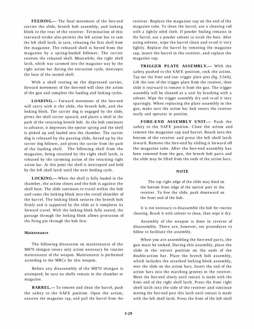
MOSSBERG M500 SHOTGUN
While very similar to the M870, the MossbergM500 has a few significant differences. The followingis a brief description of the differences that affectoperation of the weapon. Figure 3-55 shows thelocation of the safety switch and the action lock lever onthe M500 shotgun. The M500 safety switch is locatedon the top of the receiver and the action lock release isto the rear of the trigger guard. The M870 has the safetyswitch in the trigger guard and the action lock release tothe front of the trigger guard. The disassembly andmaintenance of the M500 is basically the same as thatof the M870 so much so that they are both currentlycovered on the same MRC. Further information on theMossberg M500 shotgun maybe found in the manualsupplied with the weapon.
Figure 3-55.—Mossberg M500 shotgun safety and actionrelease.
MK 87 MOD 1 LINE-THROWINGRIFLE ADAPTER KIT
LEARNING OBJECTIVE Discuss the Mk 87Mod 1 line-throwing kit and describe what isneeded in preparation for firing.
This kit redates the Mk 87 Mod O kit that replacedthe 45/70 line-throwing gun. Included in the kit are 6projectiles, 1 launcher,18 chemical light wands, and 1recoil pad. The line-throwing assembly (launcher,projectile, and canister) is designed to be used with theM14 and Ml 6A1 rifles and applicable grenadecartridges (M64 and M195, respectively).
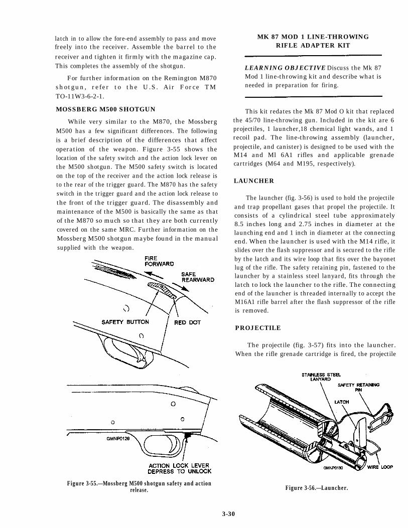
LAUNCHER
The launcher (fig. 3-56) is used to hold the projectileand trap propellant gases that propel the projectile. Itconsists of a cylindrical steel tube approximately8.5 inches long and 2.75 inches in diameter at thelaunching end and 1 inch in diameter at the connectingend. When the launcher is used with the M14 rifle, itslides over the flash suppressor and is secured to the rifleby the latch and its wire loop that fits over the bayonetlug of the rifle. The safety retaining pin, fastened to thelauncher by a stainless steel lanyard, fits through thelatch to lock the launcher to the rifle. The connectingend of the launcher is threaded internally to accept theM16A1 rifle barrel after the flash suppressor of the rifleis removed.
PROJECTILE
The projectile (fig. 3-57) fits into the launcher.When the rifle grenade cartridge is fired, the projectile
Figure 3-56.—Launcher.
3-30
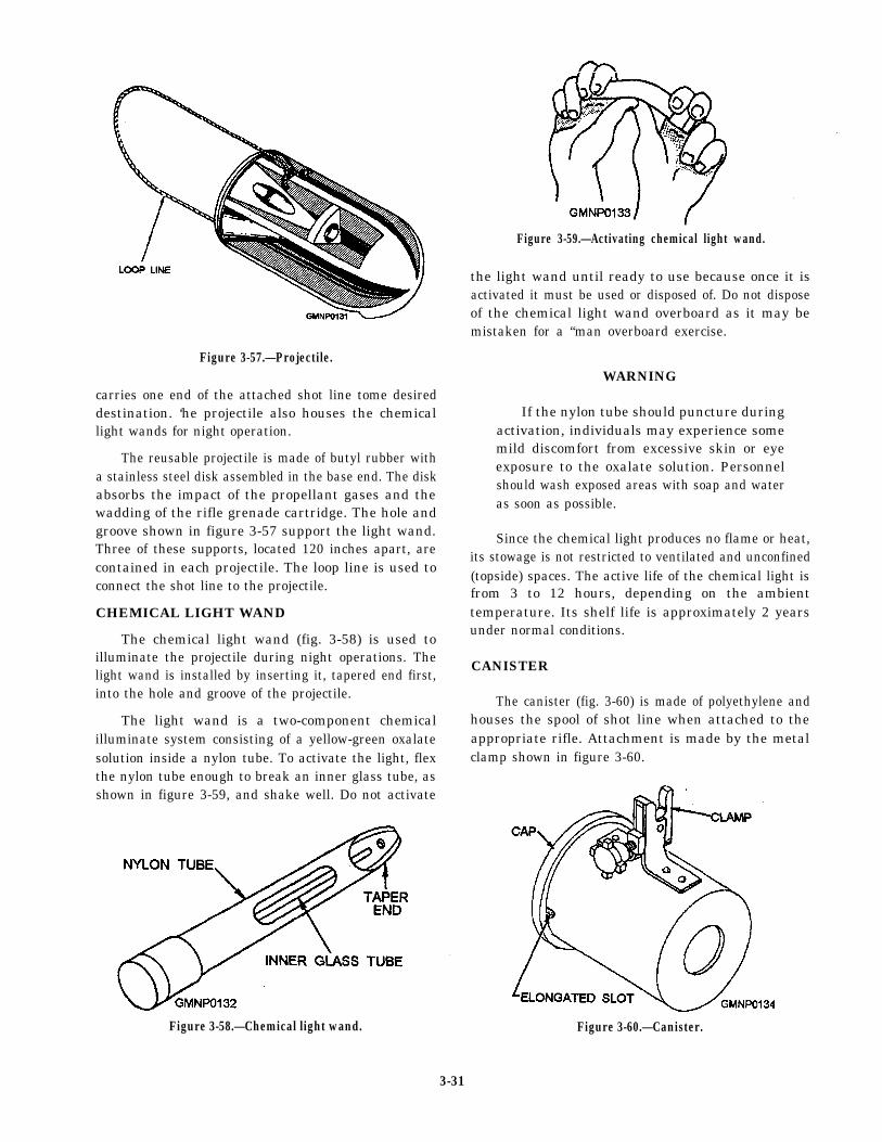
Figure 3-59.—Activating chemical light wand.
the light wand until ready to use because once it isactivated it must be used or disposed of. Do not disposeof the chemical light wand overboard as it may bemistaken for a “man overboard exercise.
Figure 3-57.—Projectile.WARNING
carries one end of the attached shot line tome desireddestination. ‘he projectile also houses the chemicallight wands for night operation.
The reusable projectile is made of butyl rubber witha stainless steel disk assembled in the base end. The diskabsorbs the impact of the propellant gases and thewadding of the rifle grenade cartridge. The hole andgroove shown in figure 3-57 support the light wand.Three of these supports, located 120 inches apart, arecontained in each projectile. The loop line is used toconnect the shot line to the projectile.
CHEMICAL LIGHT WAND
The chemical light wand (fig. 3-58) is used toilluminate the projectile during night operations. Thelight wand is installed by inserting it, tapered end first,into the hole and groove of the projectile.
The light wand is a two-component chemicalilluminate system consisting of a yellow-green oxalatesolution inside a nylon tube. To activate the light, flexthe nylon tube enough to break an inner glass tube, asshown in figure 3-59, and shake well. Do not activate
Figure 3-58.—Chemical light wand.
If the nylon tube should puncture duringactivation, individuals may experience somemild discomfort from excessive skin or eyeexposure to the oxalate solution. Personnelshould wash exposed areas with soap and wateras soon as possible.
Since the chemical light produces no flame or heat,its stowage is not restricted to ventilated and unconfined(topside) spaces. The active life of the chemical light isfrom 3 to 12 hours, depending on the ambienttemperature. Its shelf life is approximately 2 yearsunder normal conditions.
CANISTER
The canister (fig. 3-60) is made of polyethylene andhouses the spool of shot line when attached to theappropriate rifle. Attachment is made by the metalclamp shown in figure 3-60.
Figure 3-60.—Canister.
3-31
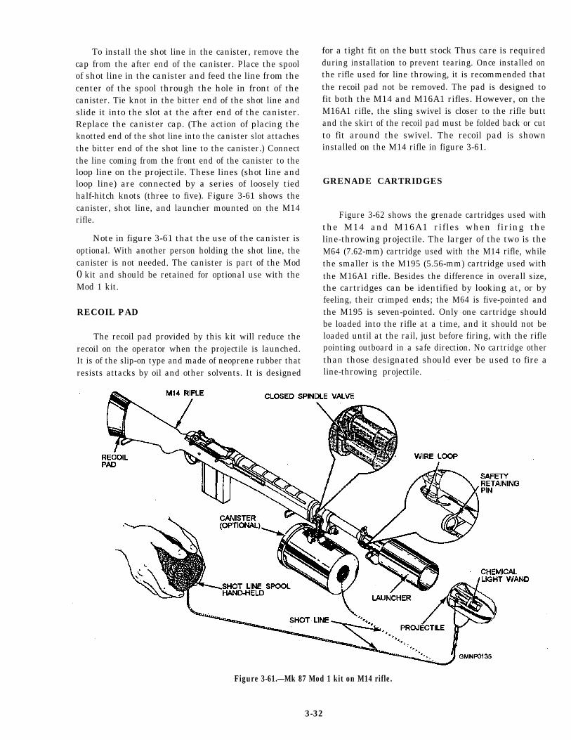
To install the shot line in the canister, remove thecap from the after end of the canister. Place the spoolof shot line in the canister and feed the line from thecenter of the spool through the hole in front of thecanister. Tie knot in the bitter end of the shot line andslide it into the slot at the after end of the canister.Replace the canister cap. (The action of placing theknotted end of the shot line into the canister slot attachesthe bitter end of the shot line to the canister.) Connectthe line coming from the front end of the canister to theloop line on the projectile. These lines (shot line andloop line) are connected by a series of loosely tiedhalf-hitch knots (three to five). Figure 3-61 shows thecanister, shot line, and launcher mounted on the M14rifle.
Note in figure 3-61 that the use of the canister isoptional. With another person holding the shot line, thecanister is not needed. The canister is part of the Mod0 kit and should be retained for optional use with theMod 1 kit.
RECOIL PAD
The recoil pad provided by this kit will reduce therecoil on the operator when the projectile is launched.It is of the slip-on type and made of neoprene rubber thatresists attacks by oil and other solvents. It is designed
for a tight fit on the butt stock Thus care is requiredduring installation to prevent tearing. Once installed onthe rifle used for line throwing, it is recommended thatthe recoil pad not be removed. The pad is designed tofit both the M14 and M16A1 rifles. However, on theM16A1 rifle, the sling swivel is closer to the rifle buttand the skirt of the recoil pad must be folded back or cutto fit around the swivel. The recoil pad is showninstalled on the M14 rifle in figure 3-61.
GRENADE CARTRIDGES
Figure 3-62 shows the grenade cartridges used withthe M14 and M16A1 rifles when firing theline-throwing projectile. The larger of the two is theM64 (7.62-mm) cartridge used with the M14 rifle, whilethe smaller is the M195 (5.56-mm) cartridge used withthe M16A1 rifle. Besides the difference in overall size,the cartridges can be identified by looking at, or byfeeling, their crimped ends; the M64 is five-pointed andthe M195 is seven-pointed. Only one cartridge shouldbe loaded into the rifle at a time, and it should not beloaded until at the rail, just before firing, with the riflepointing outboard in a safe direction. No cartridge otherthan those designated should ever be used to fire aline-throwing projectile.
Figure 3-61.—Mk 87 Mod 1 kit on M14 rifle.
3-32
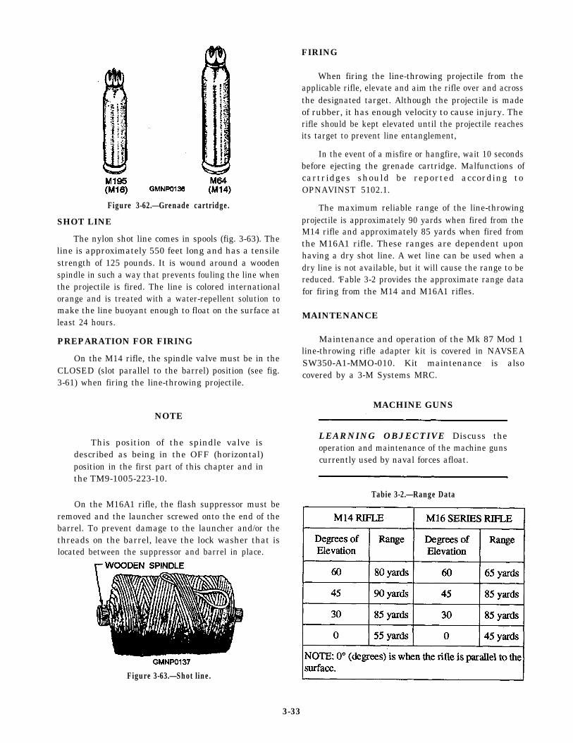
FIRING
Figure 3-62.—Grenade cartridge.
SHOT LINE
The nylon shot line comes in spools (fig. 3-63). Theline is approximately 550 feet long and has a tensilestrength of 125 pounds. It is wound around a woodenspindle in such a way that prevents fouling the line whenthe projectile is fired. The line is colored internationalorange and is treated with a water-repellent solution tomake the line buoyant enough to float on the surface atleast 24 hours.
PREPARATION FOR FIRING
On the M14 rifle, the spindle valve must be in theCLOSED (slot parallel to the barrel) position (see fig.3-61) when firing the line-throwing projectile.
NOTE
This position of the spindle valve isdescribed as being in the OFF (horizontal)position in the first part of this chapter and inthe TM9-1005-223-10.
On the M16A1 rifle, the flash suppressor must beremoved and the launcher screwed onto the end of thebarrel. To prevent damage to the launcher and/or thethreads on the barrel, leave the lock washer that islocated between the suppressor and barrel in place.
Figure 3-63.—Shot line.
When firing the line-throwing projectile from theapplicable rifle, elevate and aim the rifle over and acrossthe designated target. Although the projectile is madeof rubber, it has enough velocity to cause injury. Therifle should be kept elevated until the projectile reachesits target to prevent line entanglement,
In the event of a misfire or hangfire, wait 10 secondsbefore ejecting the grenade cartridge. Malfunctions ofcartridges should be reported according toOPNAVINST 5102.1.
The maximum reliable range of the line-throwingprojectile is approximately 90 yards when fired from theM14 rifle and approximately 85 yards when fired fromthe M16A1 rifle. These ranges are dependent uponhaving a dry shot line. A wet line can be used when adry line is not available, but it will cause the range to bereduced. ‘Fable 3-2 provides the approximate range datafor firing from the M14 and M16A1 rifles.
MAINTENANCE
Maintenance and operation of the Mk 87 Mod 1line-throwing rifle adapter kit is covered in NAVSEASW350-A1-MMO-010. Kit maintenance is alsocovered by a 3-M Systems MRC.
MACHINE GUNS
LEARNING OBJECTIVE Discuss theoperation and maintenance of the machine gunscurrently used by naval forces afloat.
Tabie 3-2.—Range Data
3-33
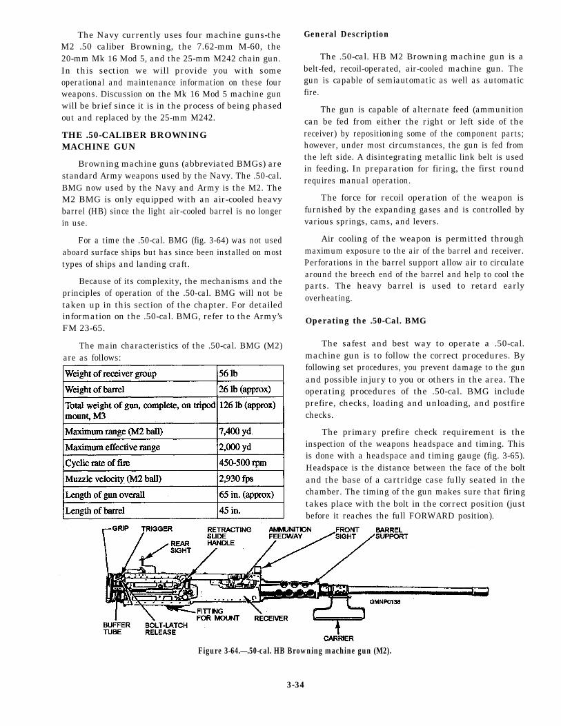
The Navy currently uses four machine guns-theM2 .50 caliber Browning, the 7.62-mm M-60, the20-mm Mk 16 Mod 5, and the 25-mm M242 chain gun.In this section we will provide you with someoperational and maintenance information on these fourweapons. Discussion on the Mk 16 Mod 5 machine gunwill be brief since it is in the process of being phasedout and replaced by the 25-mm M242.
THE .50-CALIBER BROWNINGMACHINE GUN
Browning machine guns (abbreviated BMGs) arestandard Army weapons used by the Navy. The .50-cal.BMG now used by the Navy and Army is the M2. TheM2 BMG is only equipped with an air-cooled heavybarrel (HB) since the light air-cooled barrel is no longerin use.
For a time the .50-cal. BMG (fig. 3-64) was not usedaboard surface ships but has since been installed on mosttypes of ships and landing craft.
Because of its complexity, the mechanisms and theprinciples of operation of the .50-cal. BMG will not betaken up in this section of the chapter. For detailedinformation on the .50-cal. BMG, refer to the Army’sFM 23-65.
The main characteristics of the .50-cal. BMG (M2)are as follows:
General Description
The .50-cal. HB M2 Browning machine gun is abelt-fed, recoil-operated, air-cooled machine gun. Thegun is capable of semiautomatic as well as automaticfire.
The gun is capable of alternate feed (ammunitioncan be fed from either the right or left side of thereceiver) by repositioning some of the component parts;however, under most circumstances, the gun is fed fromthe left side. A disintegrating metallic link belt is usedin feeding. In preparation for firing, the first roundrequires manual operation.
The force for recoil operation of the weapon isfurnished by the expanding gases and is controlled byvarious springs, cams, and levers.
Air cooling of the weapon is permitted throughmaximum exposure to the air of the barrel and receiver.Perforations in the barrel support allow air to circulatearound the breech end of the barrel and help to cool theparts. The heavy barrel is used to retard earlyoverheating.
Operating the .50-Cal. BMG
The safest and best way to operate a .50-cal.machine gun is to follow the correct procedures. Byfollowing set procedures, you prevent damage to the gunand possible injury to you or others in the area. Theoperating procedures of the .50-cal. BMG includeprefire, checks, loading and unloading, and postfirechecks.
The primary prefire check requirement is theinspection of the weapons headspace and timing. Thisis done with a headspace and timing gauge (fig. 3-65).Headspace is the distance between the face of the boltand the base of a cartridge case fully seated in thechamber. The timing of the gun makes sure that firingtakes place with the bolt in the correct position (justbefore it reaches the full FORWARD position).
Figure 3-64.—.50-cal. HB Browning machine gun (M2).
3-34
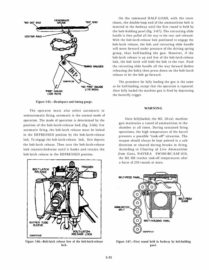
Figure 3-65.—Headspace and timing gauge.
The operator must also select automatic orsemiautomatic firing; automatic is the normal mode ofoperation. The mode of operation is determined by theposition of the bolt-latch-release lock (fig. 3-66). Forautomatic firing, the bolt-latch release must be lockedin the DEPRESSED position by the bolt-latch-releaselock. To engage the bolt-latch-release lock, first depressthe bolt-latch release. Then turn the bolt-latch-releaselock counterclockwise until it hooks and retains thebolt-latch release in the DEPRESSED position.
On the command HALF-LOAD, with the covercloses, the double-loop end of the ammunition belt isinserted in the feedway until the first round is held bythe belt-holding pawl (fig. 3-67). The retracting slidehandle is then pulled all the way to the rear and released.With the bolt-latch-release lock positioned to engage thebolt-latch release, the bolt and retracting slide handlewill move forward under pressure of the driving springgroup, thus half-loading the gun. However, if thebolt-latch release is up and free of the bolt-latch-releaselock, the bolt latch will hold the bolt to the rear. Pushthe retracting slide handle all the way forward (beforereleasing the bolt); then press down on the bolt-latchrelease to let the bolt go forward.
The procedure for fully loading the gun is the sameas for half-loading, except that the operation is repeated.Once fully loaded the machine gun is fired by depressingthe butterfly trigger.
WARNING
Once fullyloaded, the M2 .50-cal. machinegun maintains a round of ammunition in thechamber at all times. During sustained firingoperations, the high temperature of the barrelpresents a possible “cook-off” situation. Theweapon should always be kept pointed in a safedirection or cleared during breaks in firing.According to Clearing of Live Ammunitionfrom Guns, NAVSEA SW300-BC-SAF-010,the M2 HB reaches cook-off temperatures aftera burst of 250 rounds or more.
Figure 3-66.—Bolt-latch release free of the bolt-latch-releaselock.
Figure 3-67.—First round held in feedway by belt-holdingpawl.
3-35
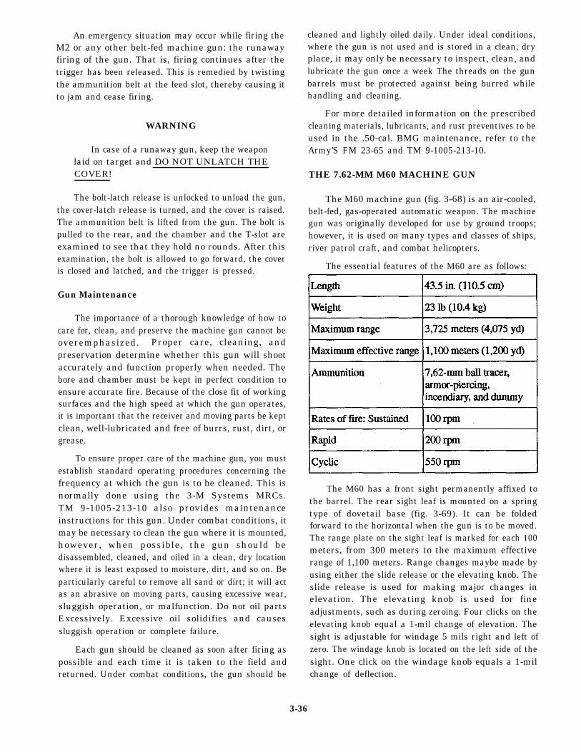
An emergency situation may occur while firing theM2 or any other belt-fed machine gun: the runawayfiring of the gun. That is, firing continues after thetrigger has been released. This is remedied by twistingthe ammunition belt at the feed slot, thereby causing itto jam and cease firing.
WARNING
In case of a runaway gun, keep the weaponlaid on target and DO NOT UNLATCH THECOVER!
The bolt-latch release is unlocked to unload the gun,the cover-latch release is turned, and the cover is raised.The ammunition belt is lifted from the gun. The bolt ispulled to the rear, and the chamber and the T-slot areexamined to see that they hold no rounds. After thisexamination, the bolt is allowed to go forward, the coveris closed and latched, and the trigger is pressed.
Gun Maintenance
The importance of a thorough knowledge of how tocare for, clean, and preserve the machine gun cannot beoveremphasized. Proper care, cleaning, andpreservation determine whether this gun will shootaccurately and function properly when needed. Thebore and chamber must be kept in perfect condition toensure accurate fire. Because of the close fit of workingsurfaces and the high speed at which the gun operates,it is important that the receiver and moving parts be keptclean, well-lubricated and free of burrs, rust, dirt, orgrease.
To ensure proper care of the machine gun, you mustestablish standard operating procedures concerning thefrequency at which the gun is to be cleaned. This isnormally done using the 3-M Systems MRCs.TM 9-1005-213-10 also provides maintenanceinstructions for this gun. Under combat conditions, itmay be necessary to clean the gun where it is mounted,however, when possible, the gun should bedisassembled, cleaned, and oiled in a clean, dry locationwhere it is least exposed to moisture, dirt, and so on. Beparticularly careful to remove all sand or dirt; it will actas an abrasive on moving parts, causing excessive wear,sluggish operation, or malfunction. Do not oil partsExcessively. Excessive oil solidifies and causessluggish operation or complete failure.
Each gun should be cleaned as soon after firing aspossible and each time it is taken to the field andreturned. Under combat conditions, the gun should be
cleaned and lightly oiled daily. Under ideal conditions,where the gun is not used and is stored in a clean, dryplace, it may only be necessary to inspect, clean, andlubricate the gun once a week The threads on the gunbarrels must be protected against being burred whilehandling and cleaning.
For more detailed information on the prescribedcleaning materials, lubricants, and rust preventives to beused in the .50-cal. BMG maintenance, refer to theArmy’S FM 23-65 and TM 9-1005-213-10.
THE 7.62-MM M60 MACHINE GUN
The M60 machine gun (fig. 3-68) is an air-cooled,belt-fed, gas-operated automatic weapon. The machinegun was originally developed for use by ground troops;however, it is used on many types and classes of ships,river patrol craft, and combat helicopters.
The essential features of the M60 are as follows:
The M60 has a front sight permanently affixed tothe barrel. The rear sight leaf is mounted on a springtype of dovetail base (fig. 3-69). It can be foldedforward to the horizontal when the gun is to be moved.The range plate on the sight leaf is marked for each 100meters, from 300 meters to the maximum effectiverange of 1,100 meters. Range changes maybe made byusing either the slide release or the elevating knob. Theslide release is used for making major changes inelevation. The elevating knob is used for fineadjustments, such as during zeroing. Four clicks on theelevating knob equal a 1-mil change of elevation. Thesight is adjustable for windage 5 mils right and left ofzero. The windage knob is located on the left side of thesight. One click on the windage knob equals a 1-milchange of deflection.
3-36
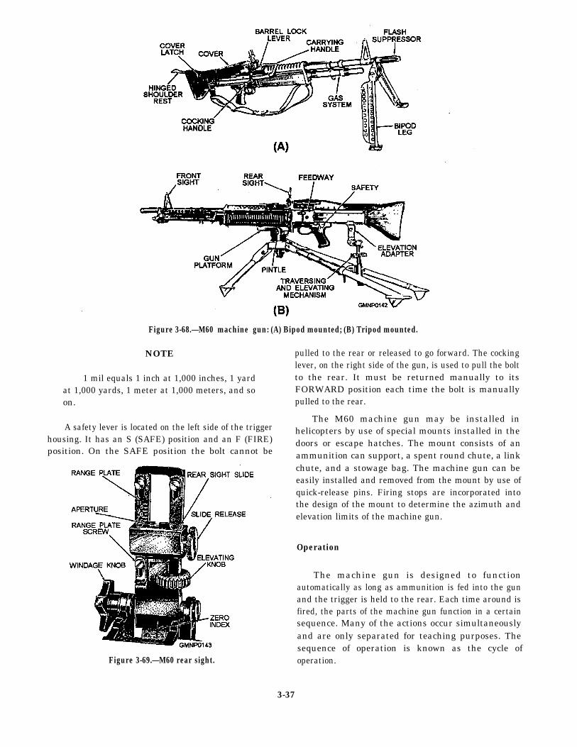
Figure 3-68.—M60 machine gun: (A) Bipod mounted; (B) Tripod mounted.
NOTE pulled to the rear or released to go forward. The cockinglever, on the right side of the gun, is used to pull the bolt
1 mil equals 1 inch at 1,000 inches, 1 yard to the rear. It must be returned manually to itsat 1,000 yards, 1 meter at 1,000 meters, and so FORWARD position each time the bolt is manually
pulled to the rear.on.
A safety lever is located on the left side of the triggerThe M60 machine gun may be installed in
housing. It has an S (SAFE) position and an F (FIRE)helicopters by use of special mounts installed in thedoors or escape hatches. The mount consists of an
position. On the SAFE position the bolt cannot be ammunition can support, a spent round chute, a link
Figure 3-69.—M60 rear sight.
chute, and a stowage bag. The machine gun can beeasily installed and removed from the mount by use ofquick-release pins. Firing stops are incorporated intothe design of the mount to determine the azimuth andelevation limits of the machine gun.
Operation
The machine gun is designed to functionautomatically as long as ammunition is fed into the gunand the trigger is held to the rear. Each time around isfired, the parts of the machine gun function in a certainsequence. Many of the actions occur simultaneouslyand are only separated for teaching purposes. Thesequence of operation is known as the cycle ofoperation.
3-37
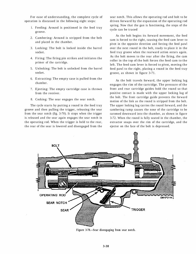
For ease of understanding, the complete cycle ofoperation is discussed in the following eight steps:
1.
2.
3.
4.
5.
6.
7.
8.
Feeding: Around is positioned in the feed traygroove.
Cambering: Around is stripped from the beltand placed in the chamber.
Locking: The bolt is locked inside the barrelsocket.
Firing: The firing pin strikes and initiates theprimer of the cartridge.
Unlocking: The bolt is unlocked from the barrelsocket.
Extracting: The empty case is pulled from thechamber.
Ejecting: The empty cartridge case is thrownfrom the receiver.
Cocking: The sear engages the sear notch.
The cycle starts by putting a round in the feed traygroove and then pulling the trigger, releasing the searfrom the sear notch (fig. 3-70). It stops when the triggeris released and the sear again engages the sear notch inthe operating rod. When the trigger is held to the rear,the rear of the sear is lowered and disengaged from the
sear notch. This allows the operating rod and bolt to bedriven forward by the expansion of the operating rodspring. Now that the gun is functioning, the steps of thecycle can be traced
As the bolt begins its forward movement, the feedcam is forced to the right, causing the feed cam lever topivot in the opposite direction and forcing the feed pawlover the next round in the belt, ready to place it in thefeed tray groove when the rearward action occurs again.As the bolt moves to the rear after the firing, the camroller in the top of the bolt forces the feed cam to theleft. The feed cam lever is forced to pivot, moving thefeed pawl to the right, placing a round in the feed traygroove, as shown in figure 3-71.
As the bolt travels forward, the upper locking lugengages the rim of the cartridge. The pressure of thefront and rear cartridge guides hold the round so thatpositive contact is made with the upper locking lug ofthe bolt. The front cartridge guide prevents the forwardmotion of the link as the round is stripped from the belt.The upper locking lug carries the round forward, and thecambering ramp causes the nose of the cartridge to becaromed downward into the chamber, as shown in figure3-72. When the round is fully seated in the chamber, theextractor snaps over the rim of the cartridge, and theejector on the face of the bolt is depressed.
Figure 3-70.—Sear disengaging from sear notch.
3-38
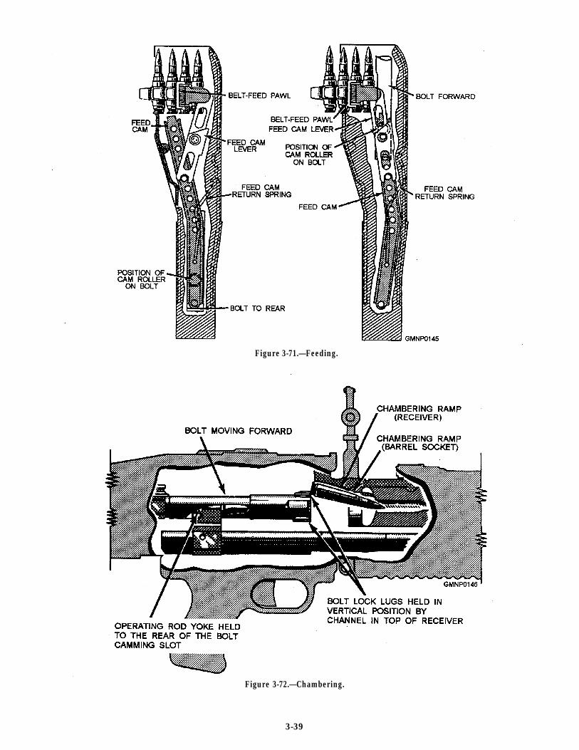
Figure 3-71.—Feeding.
Figure 3-72.—Chambering.
3-39
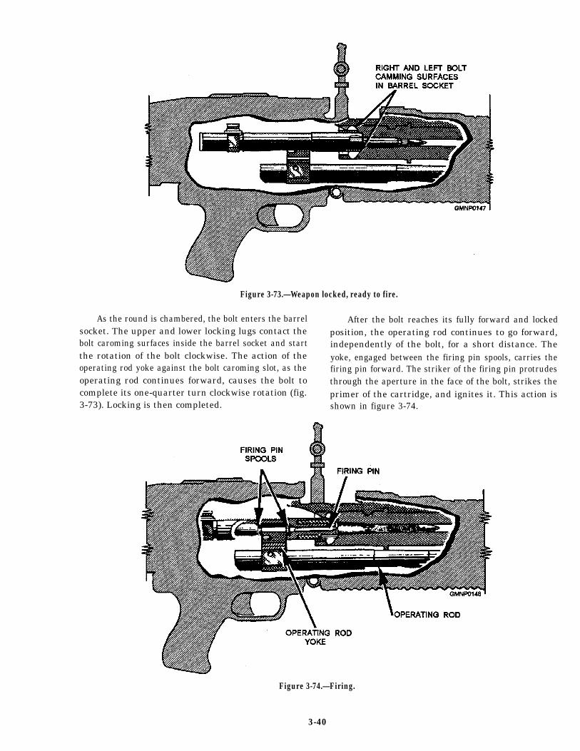
Figure 3-73.—Weapon locked, ready to fire.
As the round is chambered, the bolt enters the barrelsocket. The upper and lower locking lugs contact thebolt caroming surfaces inside the barrel socket and startthe rotation of the bolt clockwise. The action of theoperating rod yoke against the bolt caroming slot, as theoperating rod continues forward, causes the bolt tocomplete its one-quarter turn clockwise rotation (fig.3-73). Locking is then completed.
After the bolt reaches its fully forward and lockedposition, the operating rod continues to go forward,independently of the bolt, for a short distance. Theyoke, engaged between the firing pin spools, carries thefiring pin forward. The striker of the firing pin protrudesthrough the aperture in the face of the bolt, strikes theprimer of the cartridge, and ignites it. This action isshown in figure 3-74.
Figure 3-74.—Firing.
3-40
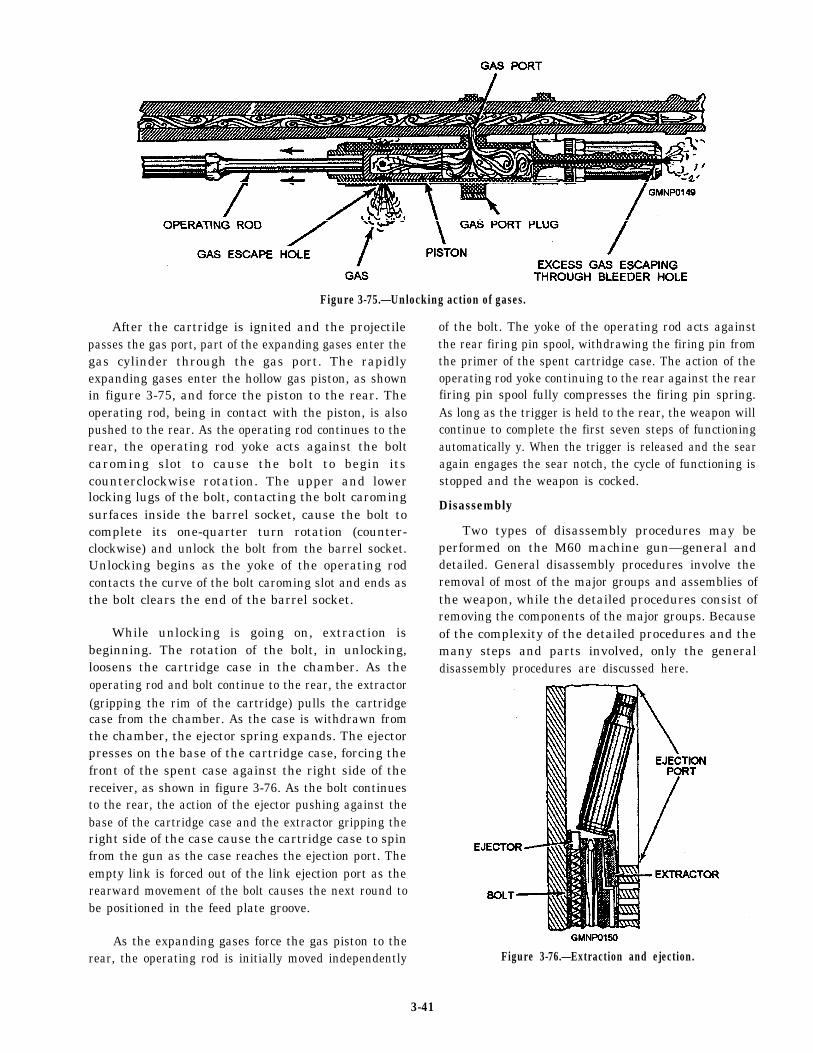
Figure 3-75.—Unlocking action of gases.
After the cartridge is ignited and the projectilepasses the gas port, part of the expanding gases enter thegas cylinder through the gas port. The rapidlyexpanding gases enter the hollow gas piston, as shownin figure 3-75, and force the piston to the rear. Theoperating rod, being in contact with the piston, is alsopushed to the rear. As the operating rod continues to therear, the operating rod yoke acts against the boltcaroming slot to cause the bolt to begin itscounterclockwise rotation. The upper and lowerlocking lugs of the bolt, contacting the bolt caromingsurfaces inside the barrel socket, cause the bolt tocomplete its one-quarter turn rotation (counter-clockwise) and unlock the bolt from the barrel socket.Unlocking begins as the yoke of the operating rodcontacts the curve of the bolt caroming slot and ends asthe bolt clears the end of the barrel socket.
While unlocking is going on, extraction isbeginning. The rotation of the bolt, in unlocking,loosens the cartridge case in the chamber. As theoperating rod and bolt continue to the rear, the extractor(gripping the rim of the cartridge) pulls the cartridgecase from the chamber. As the case is withdrawn fromthe chamber, the ejector spring expands. The ejectorpresses on the base of the cartridge case, forcing thefront of the spent case against the right side of thereceiver, as shown in figure 3-76. As the bolt continuesto the rear, the action of the ejector pushing against thebase of the cartridge case and the extractor gripping theright side of the case cause the cartridge case to spinfrom the gun as the case reaches the ejection port. Theempty link is forced out of the link ejection port as therearward movement of the bolt causes the next round tobe positioned in the feed plate groove.
As the expanding gases force the gas piston to therear, the operating rod is initially moved independently
of the bolt. The yoke of the operating rod acts againstthe rear firing pin spool, withdrawing the firing pin fromthe primer of the spent cartridge case. The action of theoperating rod yoke continuing to the rear against the rearfiring pin spool fully compresses the firing pin spring.As long as the trigger is held to the rear, the weapon willcontinue to complete the first seven steps of functioningautomatically y. When the trigger is released and the searagain engages the sear notch, the cycle of functioning isstopped and the weapon is cocked.
Disassembly
Two types of disassembly procedures may beperformed on the M60 machine gun—general anddetailed. General disassembly procedures involve theremoval of most of the major groups and assemblies ofthe weapon, while the detailed procedures consist ofremoving the components of the major groups. Becauseof the complexity of the detailed procedures and themany steps and parts involved, only the generaldisassembly procedures are discussed here.
Figure 3-76.—Extraction and ejection.
3-41
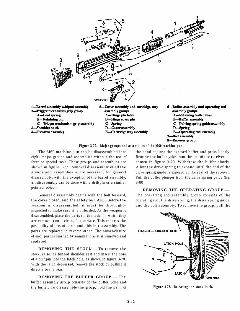
Figure 3-77.—Major groups and assemblies of the M60 machine gun.
The M60 machine gun can be disassembled intoeight major groups and assemblies without the use offorce or special tools. These groups and assemblies areshown in figure 3-77. Removal disassembly of all thegroups and assemblies is not necessary for generaldisassembly. with the exception of the barrel assembly,all disassembly can be done with a driftpin or a similarpointed object.
General disassembly begins with the bolt forward,the cover closed, and the safety on SAFE. Before theweapon is disassembled, it must be thoroughlyinspected to make sure it is unloaded. As the weapon isdisassembled, place the parts (in the order in which theyare removed) on a clean, flat surface. This reduces thepossibility of loss of parts and aids in reassembly. Theparts are replaced in reverse order. The nomenclatureof each part is learned by naming it as it is removed andreplaced
REMOVING THE STOCK— To remove thestock, raise the hinged shoulder rest and insert the noseof a driftpin into the latch hole, as shown in figure 3-78.With the latch depressed, remove the stock by pulling itdirectly to the rear.
REMOVING THE BUFFER GROUP.— Thebuffer assembly group consists of the buffer yoke andthe buffer. To disassemble the group, hold the palm of
the hand against the exposed buffer and press lightly.Remove the buffer yoke from the top of the receiver, asshown in figure 3-79. Withdraw the buffer slowly.Allow the drive spring to expand until the end of thedrive spring guide is exposed at the rear of the receiver.Pull the buffer plunger from the drive spring guide (fig.3-80).
REMOVING THE OPERATING GROUP.— The operating rod assembly group consists of theoperating rod, the drive spring, the drive spring guide,and the bolt assembly. To remove the group, pull the
Figure 3-78.—Releasing the stock latch.
3-42
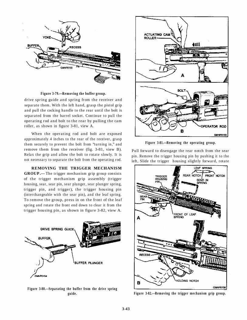
Figure 3-79.—Removing the buffer group.
drive spring guide and spring from the receiver andseparate them. With the left hand, grasp the pistol gripand pull the cocking handle to the rear until the bolt isseparated from the barrel socket. Continue to pull theoperating rod and bolt to the rear by pulling the camroller, as shown in figure 3-81, view A.
When the operating rod and bolt are exposedapproximately 4 inches to the rear of the receiver, graspthem securely to prevent the bolt from “turning in,” andremove them from the receiver (fig. 3-81, view B).Relax the grip and allow the bolt to rotate slowly. It isnot necessary to separate the bolt from the operating rod.
REMOVING THE TRIGGER MECHANISMGROUP.— The trigger mechanism grip group consistsof the trigger mechanism grip assembly (triggerhousing, sear, sear pin, sear plunger, sear plunger spring,trigger pin, and trigger), the trigger housing pin(interchangeable with the sear pin), and the leaf spring.To remove the group, press in on the front of the leafspring and rotate the front end down to clear it from thetrigger housing pin, as shown in figure 3-82, view A.
Figure 3-80.—Separating the buffer from the drive springguide.
Figure 3-81.—Removing the operating group.
Pull forward to disengage the rear notch from the searpin. Remove the trigger housing pin by pushing it to theleft, Slide the trigger housing slightly forward, rotate
Figure 3-82.—Removing the trigger mechanism grip group.
3-43
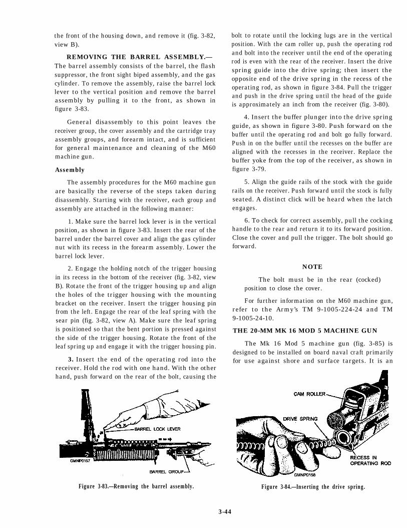
the front of the housing down, and remove it (fig. 3-82,view B).
REMOVING THE BARREL ASSEMBLY.— The barrel assembly consists of the barrel, the flashsuppressor, the front sight biped assembly, and the gascylinder. To remove the assembly, raise the barrel locklever to the vertical position and remove the barrelassembly by pulling it to the front, as shown infigure 3-83.
General disassembly to this point leaves thereceiver group, the cover assembly and the cartridge trayassembly groups, and forearm intact, and is sufficientfor general maintenance and cleaning of the M60machine gun.
Assembly
The assembly procedures for the M60 machine gunare basically the reverse of the steps taken duringdisassembly. Starting with the receiver, each group andassembly are attached in the following manner:
1. Make sure the barrel lock lever is in the verticalposition, as shown in figure 3-83. Insert the rear of thebarrel under the barrel cover and align the gas cylindernut with its recess in the forearm assembly. Lower thebarrel lock lever.
2. Engage the holding notch of the trigger housingin its recess in the bottom of the receiver (fig. 3-82, viewB). Rotate the front of the trigger housing up and alignthe holes of the trigger housing with the mountingbracket on the receiver. Insert the trigger housing pinfrom the left. Engage the rear of the leaf spring with thesear pin (fig. 3-82, view A). Make sure the leaf springis positioned so that the bent portion is pressed againstthe side of the trigger housing. Rotate the front of theleaf spring up and engage it with the trigger housing pin.
3. Insert the end of the operating rod into thereceiver. Hold the rod with one hand. With the otherhand, push forward on the rear of the bolt, causing the
Figure 3-83.—Removing the barrel assembly.
bolt to rotate until the locking lugs are in the verticalposition. With the cam roller up, push the operating rodand bolt into the receiver until the end of the operatingrod is even with the rear of the receiver. Insert the drivespring guide into the drive spring; then insert theopposite end of the drive spring in the recess of theoperating rod, as shown in figure 3-84. Pull the triggerand push in the drive spring until the head of the guideis approximately an inch from the receiver (fig. 3-80).
4. Insert the buffer plunger into the drive springguide, as shown in figure 3-80. Push forward on thebuffer until the operating rod and bolt go fully forward.Push in on the buffer until the recesses on the buffer arealigned with the recesses in the receiver. Replace thebuffer yoke from the top of the receiver, as shown infigure 3-79.
5. Align the guide rails of the stock with the guiderails on the receiver. Push forward until the stock is fullyseated. A distinct click will be heard when the latchengages.
6. To check for correct assembly, pull the cockinghandle to the rear and return it to its forward position.Close the cover and pull the trigger. The bolt should goforward.
NOTE
The bolt must be in the rear (cocked)position to close the cover.
For further information on the M60 machine gun,refer to the Army’s TM 9-1005-224-24 and TM9-1005-24-10.
THE 20-MM MK 16 MOD 5 MACHINE GUN
The Mk 16 Mod 5 machine gun (fig. 3-85) isdesigned to be installed on board naval craft primarilyfor use against shore and surface targets. It is an
Figure 3-84.—Inserting the drive spring.
3-44
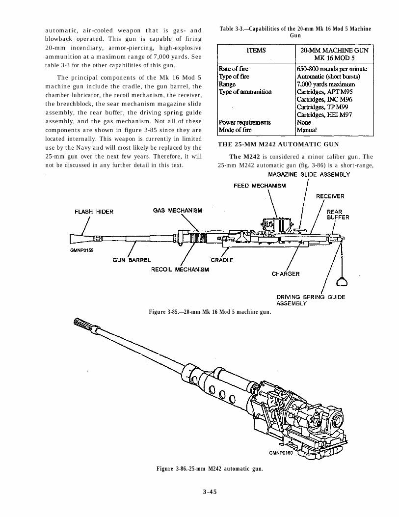
automatic, air-cooled weapon that is gas- andblowback operated. This gun is capable of firing20-mm incendiary, armor-piercing, high-explosiveammunition at a maximum range of 7,000 yards. Seetable 3-3 for the other capabilities of this gun.
The principal components of the Mk 16 Mod 5machine gun include the cradle, the gun barrel, thechamber lubricator, the recoil mechanism, the receiver,the breechblock, the sear mechanism magazine slideassembly, the rear buffer, the driving spring guideassembly, and the gas mechanism. Not all of thesecomponents are shown in figure 3-85 since they arelocated internally. This weapon is currently in limiteduse by the Navy and will most likely be replaced by the25-mm gun over the next few years. Therefore, it willnot be discussed in any further detail in this text.
Table 3-3.—Capabilities of the 20-mm Mk 16 Mod 5 MachineGun
THE 25-MM M242 AUTOMATIC GUN
The M242 is considered a minor caliber gun. The25-mm M242 automatic gun (fig. 3-86) is a short-range,
Figure 3-85.—20-mm Mk 16 Mod 5 machine gun.
Figure 3-86.-25-mm M242 automatic gun.
3-45
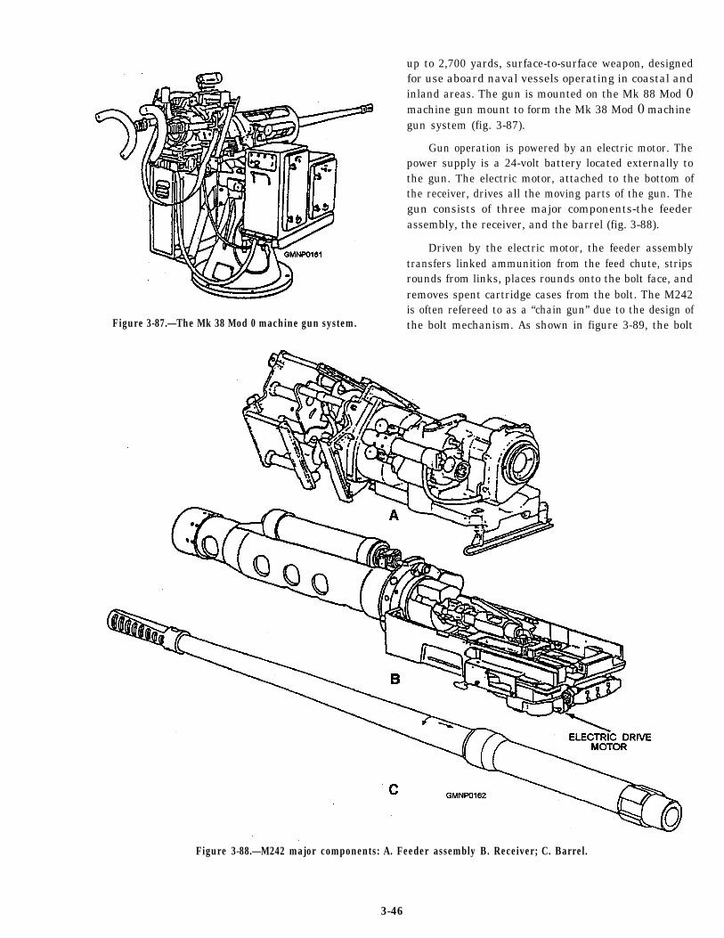
Figure 3-87.—The Mk 38 Mod 0 machine gun system.
up to 2,700 yards, surface-to-surface weapon, designedfor use aboard naval vessels operating in coastal andinland areas. The gun is mounted on the Mk 88 Mod 0machine gun mount to form the Mk 38 Mod 0 machinegun system (fig. 3-87).
Gun operation is powered by an electric motor. Thepower supply is a 24-volt battery located externally tothe gun. The electric motor, attached to the bottom ofthe receiver, drives all the moving parts of the gun. Thegun consists of three major components-the feederassembly, the receiver, and the barrel (fig. 3-88).
Driven by the electric motor, the feeder assemblytransfers linked ammunition from the feed chute, stripsrounds from links, places rounds onto the bolt face, andremoves spent cartridge cases from the bolt. The M242is often refereed to as a “chain gun” due to the design ofthe bolt mechanism. As shown in figure 3-89, the bolt
Figure 3-88.—M242 major components: A. Feeder assembly B. Receiver; C. Barrel.
3-46
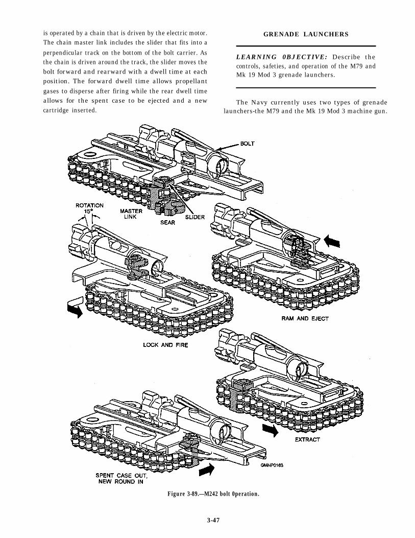
is operated by a chain that is driven by the electric motor.The chain master link includes the slider that fits into a
perpendicular track on the bottom of the bolt carrier. Asthe chain is driven around the track, the slider moves thebolt forward and rearward with a dwell time at eachposition. The forward dwell time allows propellantgases to disperse after firing while the rear dwell timeallows for the spent case to be ejected and a newcartridge inserted.
GRENADE LAUNCHERS
LEARNING 0BJECTIVE: Describe thecontrols, safeties, and operation of the M79 andMk 19 Mod 3 grenade launchers.
The Navy currently uses two types of grenadelaunchers-the M79 and the Mk 19 Mod 3 machine gun.
Figure 3-89.—M242 bolt 0peration.
3-47
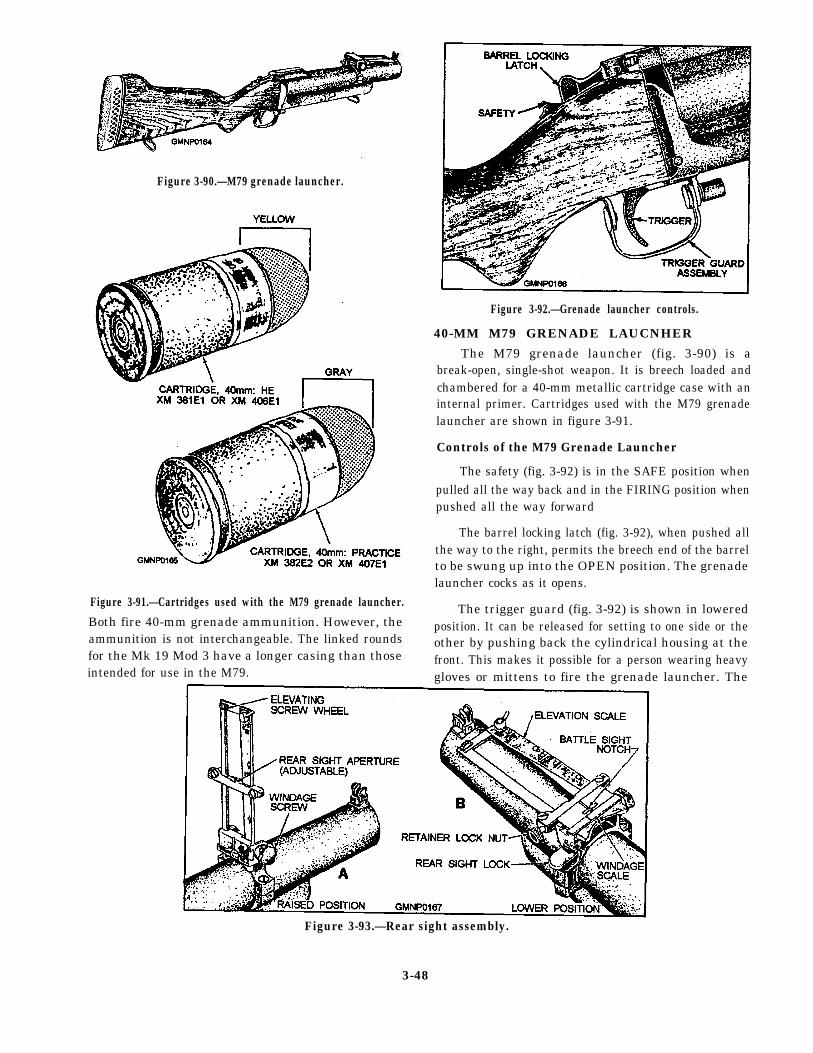
Figure 3-90.—M79 grenade launcher.
Figure 3-92.—Grenade launcher controls.
40-MM M79 GRENADE LAUCNHER
Figure 3-91.—Cartridges used with the M79 grenade launcher.
Both fire 40-mm grenade ammunition. However, theammunition is not interchangeable. The linked roundsfor the Mk 19 Mod 3 have a longer casing than thoseintended for use in the M79.
The M79 grenade launcher (fig. 3-90) is abreak-open, single-shot weapon. It is breech loaded andchambered for a 40-mm metallic cartridge case with aninternal primer. Cartridges used with the M79 grenadelauncher are shown in figure 3-91.
Controls of the M79 Grenade Launcher
The safety (fig. 3-92) is in the SAFE position whenpulled all the way back and in the FIRING position whenpushed all the way forward
The barrel locking latch (fig. 3-92), when pushed allthe way to the right, permits the breech end of the barrelto be swung up into the OPEN position. The grenadelauncher cocks as it opens.
The trigger guard (fig. 3-92) is shown in loweredposition. It can be released for setting to one side or theother by pushing back the cylindrical housing at thefront. This makes it possible for a person wearing heavygloves or mittens to fire the grenade launcher. The
Figure 3-93.—Rear sight assembly.
3-48
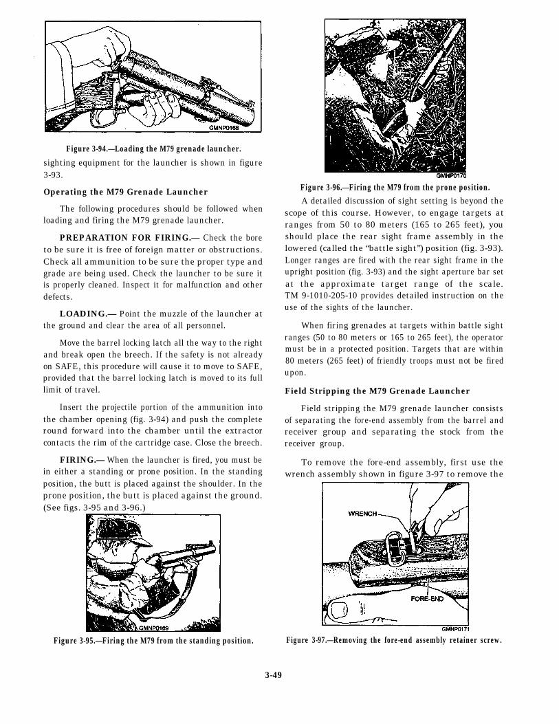
Figure 3-94.—Loading the M79 grenade launcher.
sighting equipment for the launcher is shown in figure3-93.
Operating the M79 Grenade Launcher
The following procedures should be followed whenloading and firing the M79 grenade launcher.
PREPARATION FOR FIRING.— Check the boreto be sure it is free of foreign matter or obstructions.Check all ammunition to be sure the proper type andgrade are being used. Check the launcher to be sure itis properly cleaned. Inspect it for malfunction and otherdefects.
LOADING.— Point the muzzle of the launcher atthe ground and clear the area of all personnel.
Move the barrel locking latch all the way to the rightand break open the breech. If the safety is not alreadyon SAFE, this procedure will cause it to move to SAFE,provided that the barrel locking latch is moved to its fulllimit of travel.
Insert the projectile portion of the ammunition intothe chamber opening (fig. 3-94) and push the completeround forward into the chamber until the extractorcontacts the rim of the cartridge case. Close the breech.
FIRING.— When the launcher is fired, you must bein either a standing or prone position. In the standingposition, the butt is placed against the shoulder. In theprone position, the butt is placed against the ground.(See figs. 3-95 and 3-96.)
Figure 3-95.—Firing the M79 from the standing position.
Figure 3-96.—Firing the M79 from the prone position.A detailed discussion of sight setting is beyond the
scope of this course. However, to engage targets atranges from 50 to 80 meters (165 to 265 feet), youshould place the rear sight frame assembly in thelowered (called the “battle sight”) position (fig. 3-93).Longer ranges are fired with the rear sight frame in theupright position (fig. 3-93) and the sight aperture bar setat the approximate target range of the scale.TM 9-1010-205-10 provides detailed instruction on theuse of the sights of the launcher.
When firing grenades at targets within battle sightranges (50 to 80 meters or 165 to 265 feet), the operatormust be in a protected position. Targets that are within80 meters (265 feet) of friendly troops must not be firedupon.
Field Stripping the M79 Grenade Launcher
Field stripping the M79 grenade launcher consistsof separating the fore-end assembly from the barrel andreceiver group and separating the stock from thereceiver group.
To remove the fore-end assembly, first use thewrench assembly shown in figure 3-97 to remove the
Figure 3-97.—Removing the fore-end assembly retainer screw.
3-49
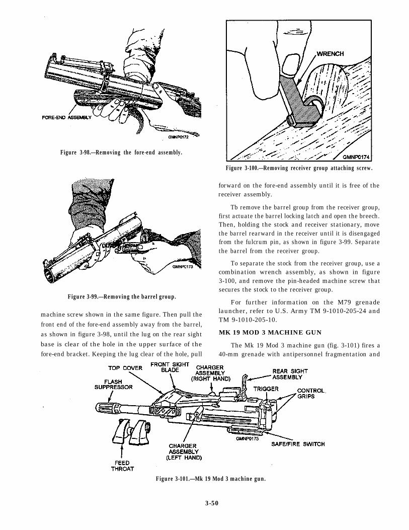
Figure 3-98.—Removing the fore-end assembly.
Figure 3-99.—Removing the barrel group.
machine screw shown in the same figure. Then pull thefront end of the fore-end assembly away from the barrel,as shown in figure 3-98, until the lug on the rear sightbase is clear of the hole in the upper surface of thefore-end bracket. Keeping the lug clear of the hole, pull
Figure 3-100.—Removing receiver group attaching screw.
forward on the fore-end assembly until it is free of thereceiver assembly.
Tb remove the barrel group from the receiver group,first actuate the barrel locking latch and open the breech.Then, holding the stock and receiver stationary, movethe barrel rearward in the receiver until it is disengagedfrom the fulcrum pin, as shown in figure 3-99. Separatethe barrel from the receiver group.
To separate the stock from the receiver group, use acombination wrench assembly, as shown in figure3-100, and remove the pin-headed machine screw thatsecures the stock to the receiver group.
For further information on the M79 grenadelauncher, refer to U.S. Army TM 9-1010-205-24 andTM 9-1010-205-10.
MK 19 MOD 3 MACHINE GUN
The Mk 19 Mod 3 machine gun (fig. 3-101) fires a40-mm grenade with antipersonnel fragmentation and
Figure 3-101.—Mk 19 Mod 3 machine gun.
3-50
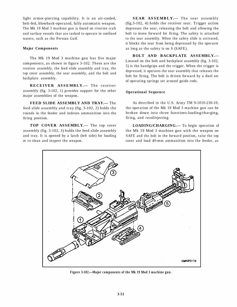
light armor-piercing capability. It is an air-cooled, SEAR ASSEMBLY.— The sear assemblybelt-fed, blowback-operated, fully automatic weapon. (fig.3-102, 4) holds the receiver sear. Trigger actionThe Mk 19 Mod 3 machine gun is found on riverine craft depresses the sear, releasing the bolt and allowing theand surface vessels that are tasked to operate in confined bolt to move forward for firing. The safety is attachedwaters, such as the Persian Gulf. to the sear assembly. When the safety slide is activated,
it blocks the sear from being depressed by the operatorMajor Components as long as the safety is on S (SAFE).
The Mk 19 Mod 3 machine gun has five majorcomponents, as shown in figure 3-102. These are thereceiver assembly, the feed slide assembly and tray, thetop cover assembly, the sear assembly, and the bolt andbackplate assembly.
RECEIVER ASSEMBLY.— The receiverassembly (fig. 3-102, 1) provides support for the othermajor assemblies of the weapon.
FEED SLIDE ASSEMBLY AND TRAY.— Thefeed slide assembly and tray (fig. 3-102, 2) holds therounds in the feeder and indexes ammunition into thefiring position.
TOP COVER ASSEMBLY.— The top coverassembly (fig. 3-102, 3) holds the feed slide assemblyand tray. It is opened by a latch (left side) for loadingor to clean and inspect the weapon.
BOLT AND BACKPLATE ASSEMBLY.—Located on the bolt and backplate assembly (fig. 3-102,5) is the handgrips and the trigger. When the trigger isdepressed, it operates the sear assembly that releases thebolt for firing. The bolt is driven forward by a duel setof operating springs set around guide rods.
Operational Sequence
As described in the U.S. Army TM 9-1010-230-10,the operation of the Mk 19 Mod 3 machine gun can bebroken down into three functions-loading/charging,firing, and recoil/ejecting.
LOADING/CHARGING.— To begin operation ofthe Mk 19 Mod 3 machine gun with the weapon onSAFE and the bolt in the forward position, raise the topcover and load 40-mm ammunition into the feeder, as
Figure 3-102.—Major components of the Mk 19 Mod 3 machine gun.
3-51
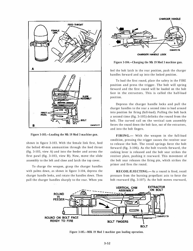
Figure 3-103.—Loading the Mk 19 Mod 3 machine gun.
shown in figure 3-103. With the female link first, feedthe belted 40-mm ammunition through the feed throat(fig. 3-103, view A) and into the feeder and across thefirst pawl (fig. 3-103, view B). Now, move the slideassembly to the left and close and latch the top cover.
To charge the weapon, grasp the charger handleswith palms down, as shown in figure 3-104, depress thecharger handle leeks, and rotate the handles down. Thenpull the charger handles sharply to the rear. When you
Figure 3-104.—Charging the Mk 19 Mod 3 machine gun.
feel the bolt latch in the rear position, push the chargerhandles forward and up into the locked position.
To load the first round, place the safety in the FIREposition and press the trigger. The bolt will springforward and the first round will be loaded on the boltface in the extractors. This is called the half-loadposition.
Depress the charger handle locks and pull thecharger handles to the rear a second time to load aroundinto position for firing (full-load). Pulling the bolt backa second time (fig. 3-105) delinks the round from thebelt. The curved rail on the vertical cam assemblyforces the round down the bolt face, out of the extractors,and into the bolt fingers.
FIRING.— With the weapon in the full-loadcondition, pressing the trigger causes the receiver searto release the bolt. The recoil springs force the boltforward (fig. 3-106). As the bolt travels forward, thecocking lever is released and the bolt sear strikes thereceiver plate, pushing it rearward. This movement ofthe bolt sear releases the firing pin, which strikes theprimer and fires the round.
RECOIL/EJECTING.— As a round is fired, recoilpressure from the burning propellant acts to force thebolt rearward (fig. 3-107). As the bolt moves rearward,
Figure 3-105.—MIK 19 Mod 3 machine gun loading operation.
3-52
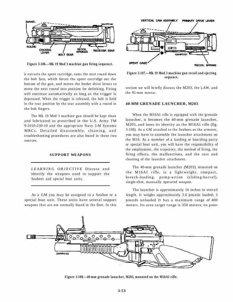
Figure 3-106.—Mk 19 Mod 3 machine gun firing sequence.
it extracts the spent cartridge, cams the next round downthe bolt face, which forces the spent cartridge out thebottom of the gun, and moves the feeder drive levers tomove the next round into position for delinking. Firingwill continue automatically as long as the trigger isdepressed. When the trigger is released, the bolt is heldin the rear position by the sear assembly with a round inthe bolt fingers.
The Mk 19 Mod 3 machine gun should be kept cleanand lubricated as prescribed in the U.S. Army TM9-1010-230-10 and the appropriate Navy 3-M SystemsMRCs. Detailed disassembly, cleaning, andtroubleshooting procedures are also found in these twosources.
SUPPORT WEAPONS
LEARNING OBJECTIVE Discuss andidentify the weapons used to support theSeabees and special boat units.
As a GM you may be assigned to a Seabee or aspecial boat unit. These units have several supportweapons that are not normally found in the fleet. In this
Figure 3-107.—Mk 19 Mod 3 machine gun recoil and ejectingsequence.
section we will briefly discuss the M203, the LAW, andthe 81-mm mortar.
40-MM GRENADE LAUNCHER, M203
When the M16A1 rifle is equipped with the grenadelauncher, it becomes the 40-mm grenade launcher,M203, and loses its identity as the M16A1 rifle (fig.3-108). As a GM attached to the Seabees as the armorer,you may have to assemble the launcher attachment onthe M16. As a member of a landing or boarding partyor special boat unit, you will have the responsibility ofthe employment, the trajectory, the method of firing, thefiring effects, the malfunctions, and the care andcleaning of the launcher attachment.
The 40-mm grenade launcher (M203), mounted onthe M16A1 rifle, is a lightweight, compact,breech-loading, pump-action (sliding-barrel),single-shot, manually operated weapon.
The launcher is approximately 16 inches in overalllength. It weighs approximately 3.6 pounds loaded; 3pounds unloaded It has a maximum range of 400meters. Its area target range is 350 meters; its point
Figure 3-108.—40-mm grenade launcher, M203, mounted on the M16A1 rifle.
3-53
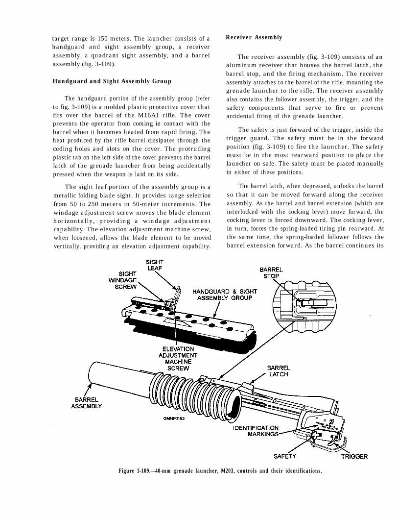
target range is 150 meters. The launcher consists of ahandguard and sight assembly group, a receiverassembly, a quadrant sight assembly, and a barrelassembly (fig. 3-109).
Handguard and Sight Assembly Group
The handguard portion of the assembly group (referto fig. 3-109) is a molded plastic protective cover thatfits over the barrel of the M16A1 rifle. The coverprevents the operator from coming in contact with thebarrel when it becomes heated from rapid firing. Theheat produced by the rifle barrel dissipates through theceding holes and slots on the cover. The protrudingplastic tab on the left side of the cover prevents the barrellatch of the grenade launcher from being accidentallypressed when the weapon is laid on its side.
The sight leaf portion of the assembly group is ametallic folding blade sight. It provides range selectionfrom 50 to 250 meters in 50-meter increments. Thewindage adjustment screw moves the blade elementhorizontally, providing a windage adjustmentcapability. The elevation adjustment machine screw,when loosened, allows the blade element to be movedvertically, providing an elevation adjustment capability.
Receiver Assembly
The receiver assembly (fig. 3-109) consists of analuminum receiver that houses the barrel latch, thebarrel stop, and the firing mechanism. The receiverassembly attaches to the barrel of the rifle, mounting thegrenade launcher to the rifle. The receiver assemblyalso contains the follower assembly, the trigger, and thesafety components that serve to fire or preventaccidental firing of the grenade launcher.
The safety is just forward of the trigger, inside thetrigger guard. The safety must be in the forwardposition (fig. 3-109) to fire the launcher. The safetymust be in the most rearward position to place thelauncher on safe. The safety must be placed manuallyin either of these positions.
The barrel latch, when depressed, unlocks the barrelso that it can be moved forward along the receiverassembly. As the barrel and barrel extension (which areinterlocked with the cocking lever) move forward, thecocking lever is forced downward. The cocking lever,in turn, forces the spring-loaded tiring pin rearward. Atthe same time, the spring-loaded follower follows thebarrel extension forward. As the barrel continues its
Figure 3-109.—40-mm grenade launcher, M203, controls and their identifications.
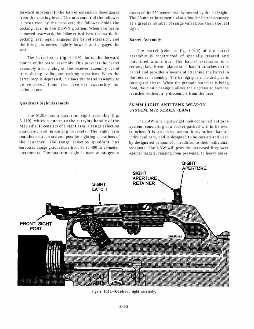
forward movement, the barrel extension disengagesfrom the cocking lever. The movement of the followeris restricted by the receiver; the follower holds thecocking lever in the DOWN position. When the barrelis moved rearward, the follower is driven rearward, thecocking lever again engages the barrel extension, andthe firing pin moves slightly forward and engages thesear.
The barrel stop (fig. 3-109) limits the forwardmotion of the barrel assembly. This prevents the barrelassembly from sliding off the receiver assembly barreltrack during loading and cocking operations. When thebarrel stop is depressed, it allows the barrel assembly tobe removed from the receiver assembly formaintenance.
Quadrant Sight Assembly
The M203 has a quadrant sight assembly (fig.3-110), which connects to the carrying handle of theM16 rifle. It consists of a sight arm, a range selectionquadrant, and mounting brackets. The sight armcontains an aperture and post for sighting operations ofthe launcher. The range selection quadrant hasembossed range graduations from 50 to 400 in 25-meterincrements. The quadrant sight is used at ranges in
excess of the 250 meters that is covered by the leaf sight.The 25-meter increments also allow for better accuracyat a greater number of range variations than the leafsight.
Barrel Assembly
The barrel (refer to fig. 3-109) of the barrelassembly is constructed of specially treated andmachined aluminum. The barrel extension is arectangular, chrome-plated steel bar. It attaches to thebarrel and provides a means of attaching the barrel tothe receiver assembly. The handgrip is a molded plasticcorrugated sleeve. When the grenade launcher is beingfired, the plastic handgrip allows the Operator to hold thelauncher without any discomfort from the heat.
66-MM LIGHT ANTITANK WEAPONSYSTEM, M72 SERIES (LAW)
The LAW is a lightweight, self-contained antitanksystem, consisting of a rocket packed within its ownlauncher. It is considered ammunition, rather than anindividual arm, and is designed to be carried and usedby designated personnel in addition to their individualweapons. The LAW will provide increased firepoweragainst targets, ranging from personnel to heavy tanks.
Figure 3-110.—Quadrant sight assembly.
3-55
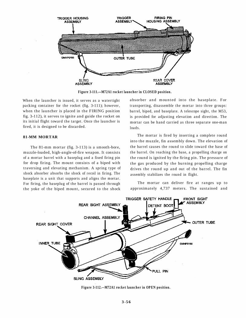
Figure 3-111.—M72A1 rocket launcher in CLOSED position.
When the launcher is issued, it serves as a watertightpacking container for the rocket (fig. 3-111); however,when the launcher is placed in the FIRING positionfig. 3-112), it serves to ignite and guide the rocket onits initial flight toward the target. Once the launcher isfired, it is designed to be discarded.
81-MM MORTAR
The 81-mm mortar (fig. 3-113) is a smooth-bore,muzzle-loaded, high-angle-of-fire weapon. It consistsof a mortar barrel with a baseplug and a fixed firing pinfor drop firing. The mount consists of a biped withtraversing and elevating mechanism. A spring type ofshock absorber absorbs the shock of recoil in firing. Thebaseplate is a unit that supports and aligns the mortar.For firing, the baseplug of the barrel is passed throughthe yoke of the biped mount, secured to the shock
absorber and mounted into the baseplate. Fortransporting, disassemble the mortar into three groups:barrel, biped, and baseplate. A telescope sight, the M53,is provided for adjusting elevation and direction. Themortar can be hand carried as three separate one-manloads.
The mortar is fired by inserting a complete roundinto the muzzle, fin assembly down. The elevation ofthe barrel causes the round to slide toward the base ofthe barrel. On reaching the base, a propelling charge onthe round is ignited by the firing pin. The pressure ofthe gas produced by the burning propelling chargedrives the round up and out of the barrel. The finassembly stabilizes the round in flight.
The mortar can deliver fire at ranges up toapproximately 4,737 meters. The sustained and
Figure 3-112.—M72A1 rocket launcher in OPEN position.
3-56
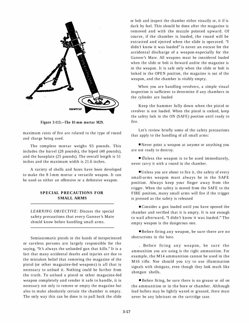
Figure 3-113.—The 81-mm mortar M29.
maximum rates of fire are related to the type of roundand charge being used.
The complete mortar weighs 93 pounds. Thisincludes the barrel (28 pounds), the biped (40 pounds),and the baseplate (25 pounds). The overall length is 51inches and the maximum width is 21.6 inches.
A variety of shells and fuzes have been developedto make the 8 l-mm mortar a versatile weapon. It canbe used as either an offensive or a defensive weapon.
SPECIAL PRECAUTIONS FORSMALL ARMS
LEARNING OBJECTIVE: Discuss the specialsafety precautions that every Gunner’s Mateshould know before handling small arms.
Semiautomatic pistols in the hands of inexperiencedor careless persons are largely responsible for thesaying, “It’s always the unloaded gun that kills.” It is afact that many accidental deaths and injuries are due tothe mistaken belief that removing the magazine of thepistol (or other magazine-fed weapons) is all that isnecessary to unload it. Nothing could be further fromthe truth. To unload a pistol or other magazine-fedweapon completely and render it safe to handle, it isnecessary not only to remove or empty the magazine butalso to make absolutely certain the chamber is empty.The only way this can be done is to pull back the slide
or bolt and inspect the chamber either visually or, it if isdark by feel. This should be done after the magazine isremoved and with the muzzle pointed upward. Ofcourse, if the chamber is loaded, the round will beextracted and ejected when the slide is operated. “Ididn’t know it was loaded” is never an excuse for theaccidental discharge of a weapon-especially for theGunner’s Mate. All weapons must be considered loadedwhen the slide or bolt is forward and/or the magazine isin the weapon. It is safe only when the slide or bolt islocked in the OPEN position, the magazine is out of theweapon, and the chamber is visibly empty.
When you are handling revolvers, a simple visualinspection is sufficient to determine if any chambers inthe cylinder are loaded
Keep the hammer fully down when the pistol orrevolver is not loaded. When the pistol is cocked, keepthe safety lock in the ON (SAFE) position until ready tofire.
Let’s review briefly some of the safety precautionsthat apply to the handling of all small arms:
Never point a weapon at anyone or anything youare not ready to destroy.
Unless the weapon is to be used immediately,never carry it with a round in the chamber.
Unless you are about to fire it, the safety of everysmall-arms weapon must always be in the SAFEposition. Always keep your finger away from thetrigger. When the safety is moved from the SAFE to theFIRE position, many small arms will fire if the triggeris pressed as the safety is released
Consider a gun loaded until you have opened thechamber and verified that it is empty. It is not enoughto wail afterward, “I didn’t know it was loaded.” Theempty weapon is the dangerous one.
Before firing any weapon, be sure there are noobstructions in the bore.
. Before firing any weapon, be sure theammunition you are using is the right ammunition. Forexample, the M14 ammunition cannot be used in theM16 rifle. Nor should you try to use illuminationsignals with shotguns, even though they look much likeshotgun shells.
Before firing, be sure there is no grease or oil onthe ammunition or in the bore or chamber. Althoughlead bullets may be lightly waxed or greased, there mustnever be any lubricant on the cartridge case.
3-57
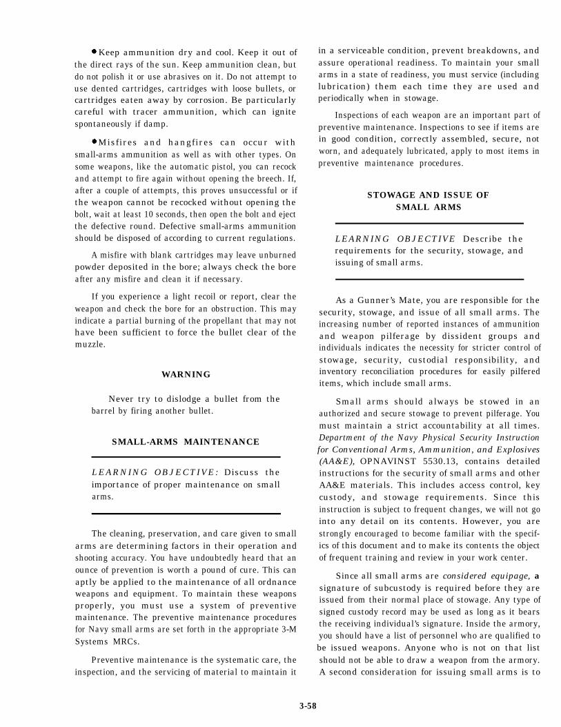
Keep ammunition dry and cool. Keep it out ofthe direct rays of the sun. Keep ammunition clean, butdo not polish it or use abrasives on it. Do not attempt touse dented cartridges, cartridges with loose bullets, orcartridges eaten away by corrosion. Be particularlycareful with tracer ammunition, which can ignitespontaneously if damp.
Misfires and hangfires can occur withsmall-arms ammunition as well as with other types. Onsome weapons, like the automatic pistol, you can recockand attempt to fire again without opening the breech. If,after a couple of attempts, this proves unsuccessful or ifthe weapon cannot be recocked without opening thebolt, wait at least 10 seconds, then open the bolt and ejectthe defective round. Defective small-arms ammunitionshould be disposed of according to current regulations.
A misfire with blank cartridges may leave unburnedpowder deposited in the bore; always check the boreafter any misfire and clean it if necessary.
If you experience a light recoil or report, clear theweapon and check the bore for an obstruction. This mayindicate a partial burning of the propellant that may nothave been sufficient to force the bullet clear of themuzzle.
WARNING
Never try to dislodge a bullet from thebarrel by firing another bullet.
SMALL-ARMS MAINTENANCE
LEARNING OBJECTIVE: Discuss theimportance of proper maintenance on smallarms.
The cleaning, preservation, and care given to smallarms are determining factors in their operation andshooting accuracy. You have undoubtedly heard that anounce of prevention is worth a pound of cure. This canaptly be applied to the maintenance of all ordnanceweapons and equipment. To maintain these weaponsproperly, you must use a system of preventivemaintenance. The preventive maintenance proceduresfor Navy small arms are set forth in the appropriate 3-MSystems MRCs.
Preventive maintenance is the systematic care, theinspection, and the servicing of material to maintain it
in a serviceable condition, prevent breakdowns, andassure operational readiness. To maintain your smallarms in a state of readiness, you must service (includinglubrication) them each time they are used andperiodically when in stowage.
Inspections of each weapon are an important part ofpreventive maintenance. Inspections to see if items arein good condition, correctly assembled, secure, notworn, and adequately lubricated, apply to most items inpreventive maintenance procedures.
STOWAGE AND ISSUE OFSMALL ARMS
LEARNING OBJECTIVE Describe therequirements for the security, stowage, andissuing of small arms.
As a Gunner’s Mate, you are responsible for thesecurity, stowage, and issue of all small arms. Theincreasing number of reported instances of ammunitionand weapon pilferage by dissident groups andindividuals indicates the necessity for stricter control ofstowage, security, custodial responsibility, andinventory reconciliation procedures for easily pilfereditems, which include small arms.
Small arms should always be stowed in anauthorized and secure stowage to prevent pilferage. Youmust maintain a strict accountability at all times.Department of the Navy Physical Security Instructionfor Conventional Arms, Ammunition, and Explosives(AA&E), OPNAVINST 5530.13, contains detailedinstructions for the security of small arms and otherAA&E materials. This includes access control, keycustody, and stowage requirements. Since thisinstruction is subject to frequent changes, we will not gointo any detail on its contents. However, you arestrongIy encouraged to become familiar with the specif-ics of this document and to make its contents the objectof frequent training and review in your work center.
Since all small arms are considered equipage, asignature of subcustody is required before they areissued from their normal place of stowage. Any type ofsigned custody record may be used as long as it bearsthe receiving individual’s signature. Inside the armory,you should have a list of personnel who are qualified tobe issued weapons. Anyone who is not on that listshould not be able to draw a weapon from the armory.A second consideration for issuing small arms is to
3-58
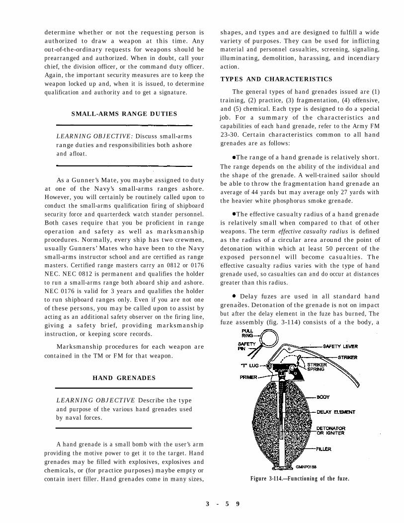
determine whether or not the requesting person isauthorized to draw a weapon at this time. Anyout-of-the-ordinary requests for weapons should beprearranged and authorized. When in doubt, call yourchief, the division officer, or the command duty officer.Again, the important security measures are to keep theweapon locked up and, when it is issued, to determinequalification and authority and to get a signature.
SMALL-ARMS RANGE DUTIES
LEARNING OBJECTIVE: Discuss small-armsrange duties and responsibilities both ashoreand afloat.
As a Gunner’s Mate, you maybe assigned to dutyat one of the Navy’s small-arms ranges ashore.However, you will certainly be routinely called upon toconduct the small-arms qualification firing of shipboardsecurity force and quarterdeck watch stander personnel.Both cases require that you be proficient in rangeoperation and safety as well as marksmanshipprocedures. Normally, every ship has two crewmen,usually Gunners’ Mates who have been to the Navysmall-arms instructor school and are certified as rangemasters. Certified range masters carry an 0812 or 0176NEC. NEC 0812 is permanent and qualifies the holderto run a small-arms range both aboard ship and ashore.NEC 0176 is valid for 3 years and qualifies the holderto run shipboard ranges only. Even if you are not oneof these persons, you may be called upon to assist byacting as an additional safety observer on the firing line,giving a safety brief, providing marksmanshipinstruction, or keeping score records.
Marksmanship procedures for each weapon arecontained in the TM or FM for that weapon.
shapes, and types and are designed to fulfill a widevariety of purposes. They can be used for inflictingmaterial and personnel casualties, screening, signaling,illuminating, demolition, harassing, and incendiaryaction.
TYPES AND CHARACTERISTICS
The general types of hand grenades issued are (1)training, (2) practice, (3) fragmentation, (4) offensive,and (5) chemical. Each type is designed to do a specialjob. For a summary of the characteristics andcapabilities of each hand grenade, refer to the Army FM23-30. Certain characteristics common to all handgrenades are as follows:
The range of a hand grenade is relatively short.The range depends on the ability of the individual andthe shape of the grenade. A well-trained sailor shouldbe able to throw the fragmentation hand grenade anaverage of 44 yards but may average only 27 yards withthe heavier white phosphorus smoke grenade.
The effective casualty radius of a hand grenadeis relatively small when compared to that of otherweapons. The term effective casualty radius is definedas the radius of a circular area around the point ofdetonation within which at least 50 percent of theexposed personnel will become casualties. Theeffective casualty radius varies with the type of handgrenade used, so casualties can and do occur at distancesgreater than this radius.
Delay fuzes are used in all standard handgrenades. Detonation of the grenade is not on impactbut after the delay element in the fuze has burned, Thefuze assembly (fig. 3-114) consists of a the body, a
HAND GRENADES
LEARNING OBJECTIVE Describe the typeand purpose of the various hand grenades usedby naval forces.
A hand grenade is a small bomb with the user’s armproviding the motive power to get it to the target. Handgrenades may be filled with explosives, explosives andchemicals, or (for practice purposes) maybe empty orcontain inert filler. Hand grenades come in many sizes, Figure 3-114.—Functioning of the fuze.
3 - 5 9
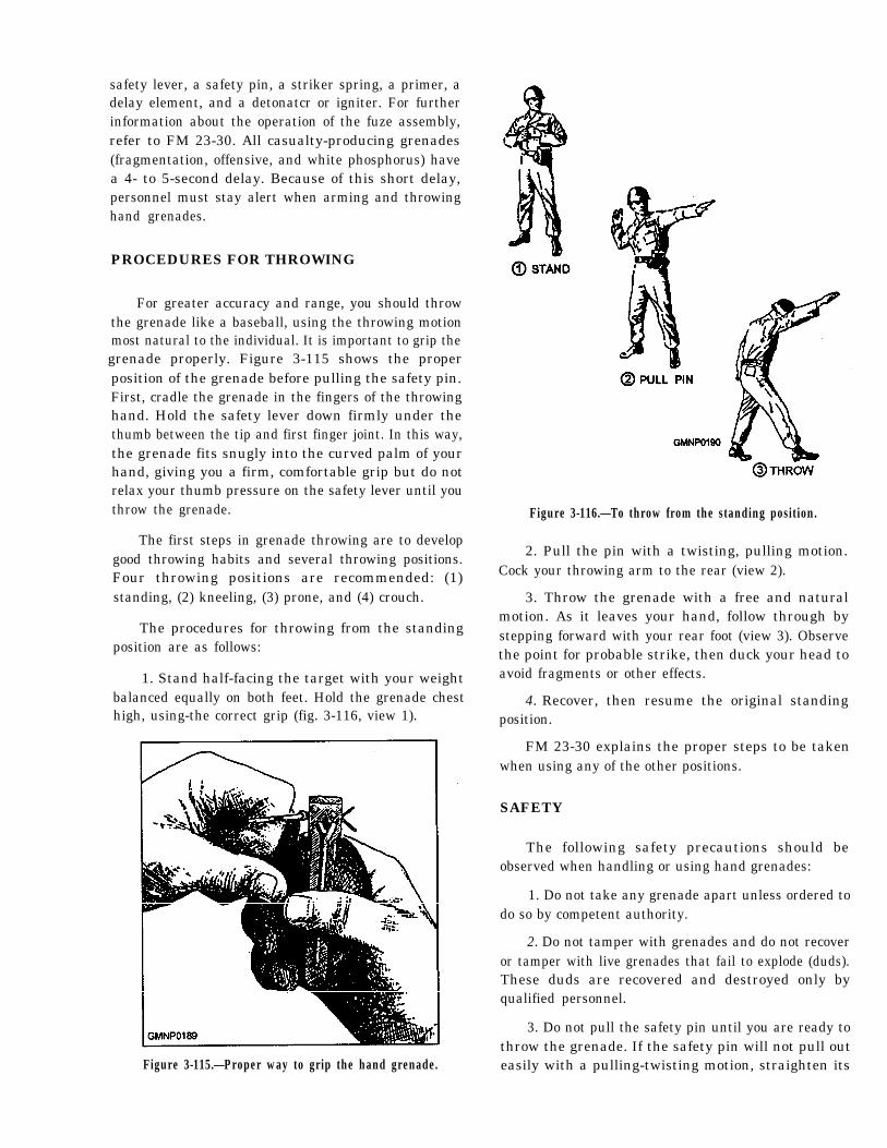
safety lever, a safety pin, a striker spring, a primer, adelay element, and a detonatcr or igniter. For furtherinformation about the operation of the fuze assembly,refer to FM 23-30. All casualty-producing grenades(fragmentation, offensive, and white phosphorus) havea 4- to 5-second delay. Because of this short delay,personnel must stay alert when arming and throwinghand grenades.
PROCEDURES FOR THROWING
For greater accuracy and range, you should throwthe grenade like a baseball, using the throwing motionmost natural to the individual. It is important to grip thegrenade properly. Figure 3-115 shows the properposition of the grenade before pulling the safety pin.First, cradle the grenade in the fingers of the throwinghand. Hold the safety lever down firmly under thethumb between the tip and first finger joint. In this way,the grenade fits snugly into the curved palm of yourhand, giving you a firm, comfortable grip but do notrelax your thumb pressure on the safety lever until youthrow the grenade.
The first steps in grenade throwing are to developgood throwing habits and several throwing positions.Four throwing positions are recommended: (1)standing, (2) kneeling, (3) prone, and (4) crouch.
The procedures for throwing from the standingposition are as follows:
1. Stand half-facing the target with your weightbalanced equally on both feet. Hold the grenade chesthigh, using-the correct grip (fig. 3-116, view 1).
Figure 3-115.—Proper way to grip the hand grenade.
Figure 3-116.—To throw from the standing position.
2. Pull the pin with a twisting, pulling motion.Cock your throwing arm to the rear (view 2).
3. Throw the grenade with a free and naturalmotion. As it leaves your hand, follow through bystepping forward with your rear foot (view 3). Observethe point for probable strike, then duck your head toavoid fragments or other effects.
4. Recover, then resume the original standingposition.
FM 23-30 explains the proper steps to be takenwhen using any of the other positions.
SAFETY
The following safety precautions should beobserved when handling or using hand grenades:
1. Do not take any grenade apart unless ordered todo so by competent authority.
2. Do not tamper with grenades and do not recoveror tamper with live grenades that fail to explode (duds).These duds are recovered and destroyed only byqualified personnel.
3. Do not pull the safety pin until you are ready tothrow the grenade. If the safety pin will not pull outeasily with a pulling-twisting motion, straighten its
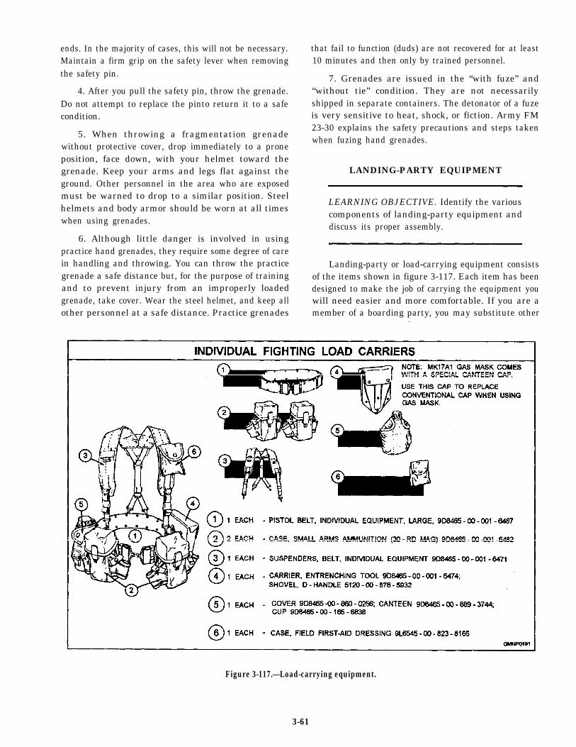
ends. In the majority of cases, this will not be necessary.Maintain a firm grip on the safety lever when removingthe safety pin.
4. After you pull the safety pin, throw the grenade.Do not attempt to replace the pinto return it to a safecondition.
5. When throwing a fragmentation grenadewithout protective cover, drop immediately to a proneposition, face down, with your helmet toward thegrenade. Keep your arms and legs flat against theground. Other personnel in the area who are exposedmust be warned to drop to a similar position. Steelhelmets and body armor should be worn at all timeswhen using grenades.
6. Although little danger is involved in usingpractice hand grenades, they require some degree of carein handling and throwing. You can throw the practicegrenade a safe distance but, for the purpose of trainingand to prevent injury from an improperly loadedgrenade, take cover. Wear the steel helmet, and keep allother personnel at a safe distance. Practice grenades
that fail to function (duds) are not recovered for at least10 minutes and then only by trained personnel.
7. Grenades are issued in the “with fuze” and“without tie” condition. They are not necessarilyshipped in separate containers. The detonator of a fuzeis very sensitive to heat, shock, or fiction. Army FM23-30 explains the safety precautions and steps takenwhen fuzing hand grenades.
LANDING-PARTY EQUIPMENT
LEARNING OBJECTIVE. Identify the variouscomponents of landing-party equipment anddiscuss its proper assembly.
Landing-party or load-carrying equipment consistsof the items shown in figure 3-117. Each item has beendesigned to make the job of carrying the equipment youwill need easier and more comfortable. If you are amember of a boarding party, you may substitute other
Figure 3-117.—Load-carrying equipment.
3-61
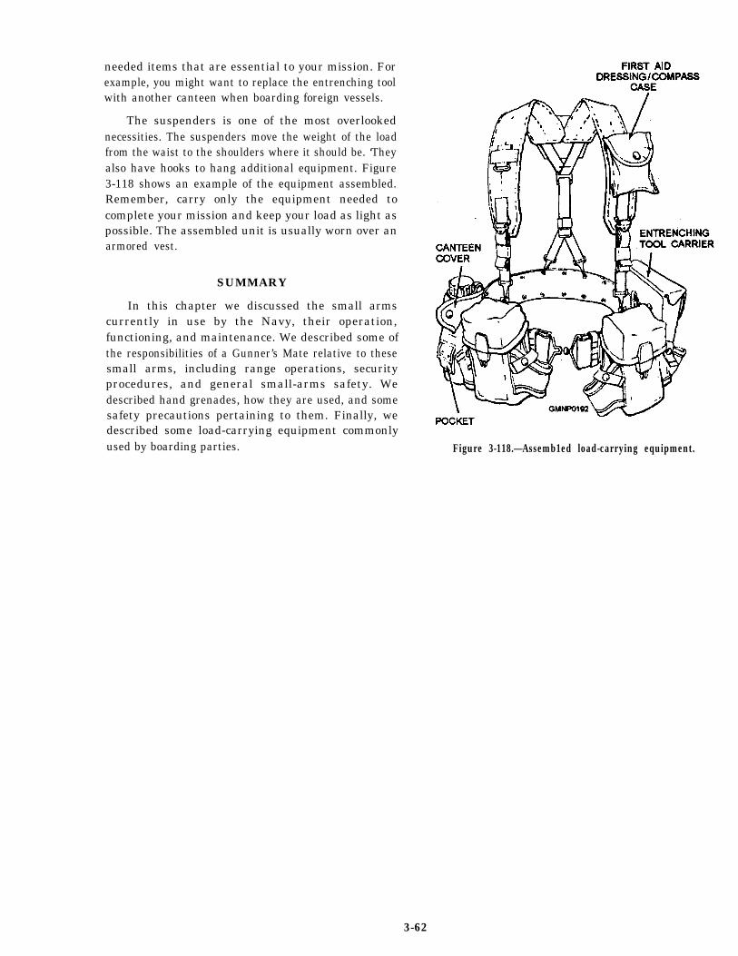
needed items that are essential to your mission. Forexample, you might want to replace the entrenching toolwith another canteen when boarding foreign vessels.
The suspenders is one of the most overlookednecessities. The suspenders move the weight of the loadfrom the waist to the shoulders where it should be. ‘Theyalso have hooks to hang additional equipment. Figure3-118 shows an example of the equipment assembled.Remember, carry only the equipment needed tocomplete your mission and keep your load as light aspossible. The assembled unit is usually worn over anarmored vest.
SUMMARY
In this chapter we discussed the small armscurrently in use by the Navy, their operation,functioning, and maintenance. We described some ofthe responsibilities of a Gunner’s Mate relative to thesesmall arms, including range operations, securityprocedures, and general small-arms safety. Wedescribed hand grenades, how they are used, and somesafety precautions pertaining to them. Finally, wedescribed some load-carrying equipment commonlyused by boarding parties. Figure 3-118.—Assemb1ed load-carrying equipment.
3-62