Embed Size (px)
Citation preview
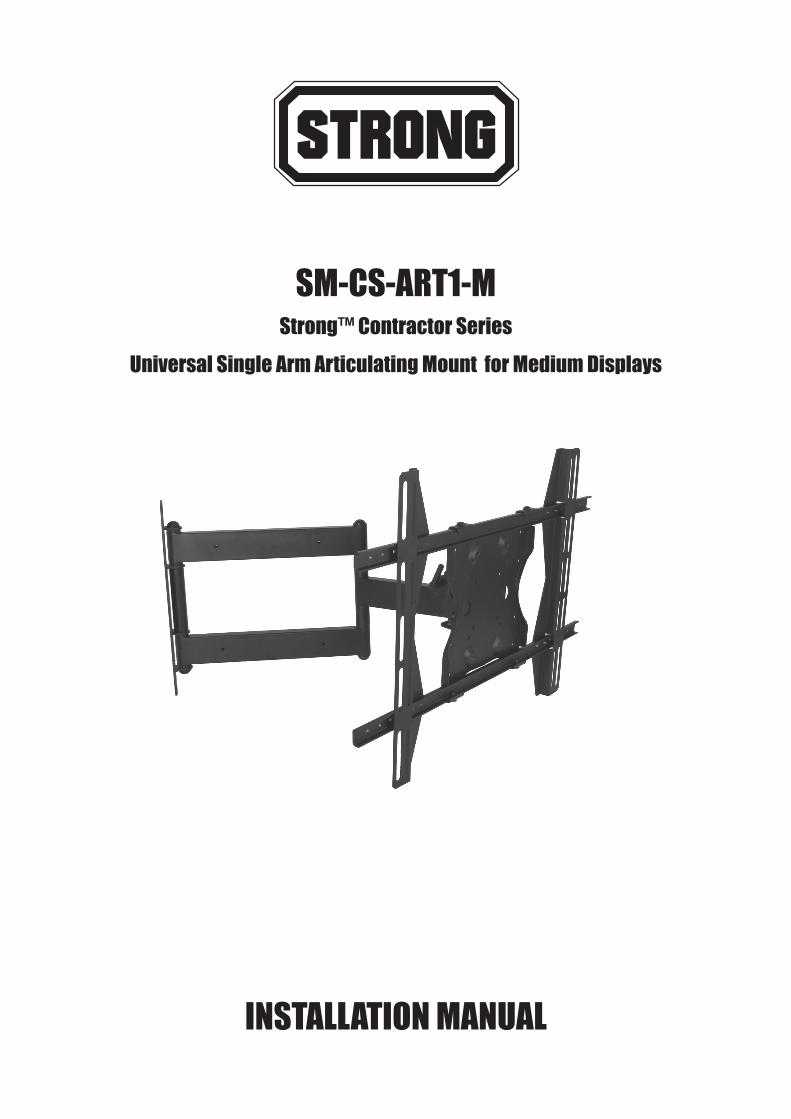
SM-CS-ART1-MStrong™ Contractor Series
Universal Single Arm Articulating Mount for Medium Displays
INSTALLATION MANUAL
2
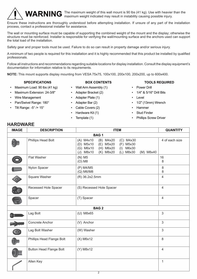
WARNING The maximum weight of this wall mount is 90 lbs (41 kg). Use with heavier than the maximum weight indicated may result in instability causing possible injury.
Ensure these instructions are thoroughly understood before attempting installation. If unsure of any part of the installation process, contact a professional installer for assistance.
The wall or mounting surface must be capable of supporting the combined weight of the mount and the display; otherwise the structure must be reinforced. Installer is responsible for verifying the wall/mounting surface and the anchors used can support the total load of the installation.
Safety gear and proper tools must be used. Failure to do so can result in property damage and/or serious injury.
A minimum of two people is required for this installation and it is highly recommended that this product be installed by qualified professionals.
Follow all instructions and recommendations regarding suitable locations for display installation. Consult the display equipment’s documentation for information relative to its requirements.
NOTE: This mount supports display mounting from VESA 75x75, 100x100, 200x100, 200x200, up to 600x400.
SPECIFICATIONS BOX CONTENTS TOOLS REQUIRED• Maximum Load: 90 lbs (41 kg) • Wall Arm Assembly (1) • Power Drill• Maximum Extension: 24-3/8" • Adapter Bracket (2) • 1/4" & 5/16" Drill Bits• Wire Management • Adapter Plate (1) • Level• Pan/Swivel Range: 180° • Adapter Bar (2) • 1/2" (13mm) Wrench• Tilt Range: -5° /+ 15° • Cable Covers (2) • Hammer
• Hardware Kit (1) • Stud Finder• Template (1) • Phillips Screw Driver
HARDWAREIMAGE DESCRIPTION ITEM QUANTITY
BAG 1Phillips Head Bolt (A) M4x10 (B) M4x20 (C) M4x30
(D) M5x10 (E) M5x20 (F) M5x30(G) M6x10 (H) M6x20 (I) M6x30 (J) M8x10 (K) M8x20 (L) M8x30 (M) M8x40
4 of each size
Flat Washer (N) M5(O) M8
16 8
Nylon Spacer (P) M4/M5(Q) M6/M8
8 8
Square Washer (R) 36.2x2.5mm 4
Recessed Hole Spacer (S) Recessed Hole Spacer 4
Spacer (T) Spacer 4
BAG 2Lag Bolt (U) M8x65 3
Concrete Anchor (V) Anchor 3
Lag Bolt Washer (W) Washer 3
Phillips Head Flange Bolt (X) M6x12 8
Button Head Flange Bolt (Y) M8x12 4
Allen Key 1
3
INSTALLATIONLayout and Drilling1. Determine general location of the display.
2. Use a stud finder to find the nearest wall stud if applicable and mark their location.
3. Tape template flat and level to wall surface, aligning the template’s slots with the stud markings on the wall.
NOTE: Use of a bead level is recommended.
NOTE: Template corners fold up to catch debris.
4. Use a pen or pointed object to mark bore locations.
ATTENTION: Before drilling, verify there is a minimum of 1-3/8" of concrete thickness to be used for the concrete anchors. Ensure to mount in a solid part of the block, generally 1" minimum from the side of the block. Cinder block must meet ASTM C-90 specifications.
ATTENTION: Concrete must be 2000 psi density minimum. Lighter density concrete may not hold concrete anchor.
ATTENTION: A standard electric drill on slow setting should be used to drill the holes instead of a hammer drill to avoid breaking out the back of the hole when entering a void or cavity.
5. Drill holes in marked locations:
• Use 1/4" bit for drilling into wooden studs.• Use 5/16" bit for drilling into concrete wall.ATTENTION: Be sure to drill holes centered within studs. Do not drill into mortar joints.
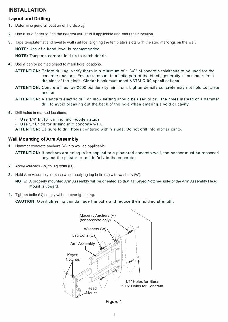
Wall Mounting of Arm Assembly1. Hammer concrete anchors (V) into wall as applicable.
ATTENTION: If anchors are going to be applied to a plastered concrete wall, the anchor must be recessed beyond the plaster to reside fully in the concrete.
2. Apply washers (W) to lag bolts (U).
3. Hold Arm Assembly in place while applying lag bolts (U) with washers (W).
NOTE: A properly mounted Arm Assembly will be oriented so that its Keyed Notches side of the Arm Assembly Head Mount is upward.
4. Tighten bolts (U) snugly without overtightening.
CAUTION: Overtightening can damage the bolts and reduce their holding strength.
Figure 1
Masonry Anchors (V)(for concrete only)
HeadMount
1/4" Holes for Studs5/16" Holes for Concrete
KeyedNotches
Washers (W)Lag Bolts (U)
Arm Assembly

4
Assemble Display Bracket
Small Displays (Up to VESA 200x200)
The display bracket does not require assembly for this display size. Proceed to the mounting section for instructions on how to mount the bracket to the display.
Large Displays (Up to VESA 600x400)
1. Align the holes in the Adapter Bars with the Adapter Plate and secure using four Bolts (X) (Figure 2).
2. Slide the Adapter Brackets onto assembled Adapter Bars. Place the assembled Bracket Assembly on the back of the display with one Adapter Bracket aligned with the mounting holes of the display. Then, slide the other Adapter Bracket in or out until it aligns with the second set of mounting holes. The Adapter Plate should be horizontally centered on the back of the display.
NOTE: Adapter Brackets can be flipped around (if required).
3. Attach the assembled Adapter Plate to the display using the screws (A – M). For displays with a hole pattern in a pocket, spacers (P or Q) go between adapter plate and display.
Figure 2
Mount Display Bracket to Display Panel
Small Displays (Up to VESA 200x200)
1. Insert two Bolts (Y) into top two holes of Adapter Plate. Leave approximately 1/4" of exposed thread (do not fully tighten).
2. Lift the display and hook it over the Head Mount by lowering the exposed portion of the top screws into the open key slots of Arm Assembly Head Mount.
3. Once in position, attach the bottom two Bolts (Y) to secure the Adapter Plate to the Arm Assembly Head Mount using the provided Allen Key to tighten down all Bolts (Figure 3 and Figure 5 “Small”).
Figure 3
Adapter Bracket
Bolts (X)
Bolts (X)
Adapter Bar
Adapter Plate
Bolts (A – I)
AdapterPlate
200mm (8")
100mm (4")
75mm (3")
Display Back
5
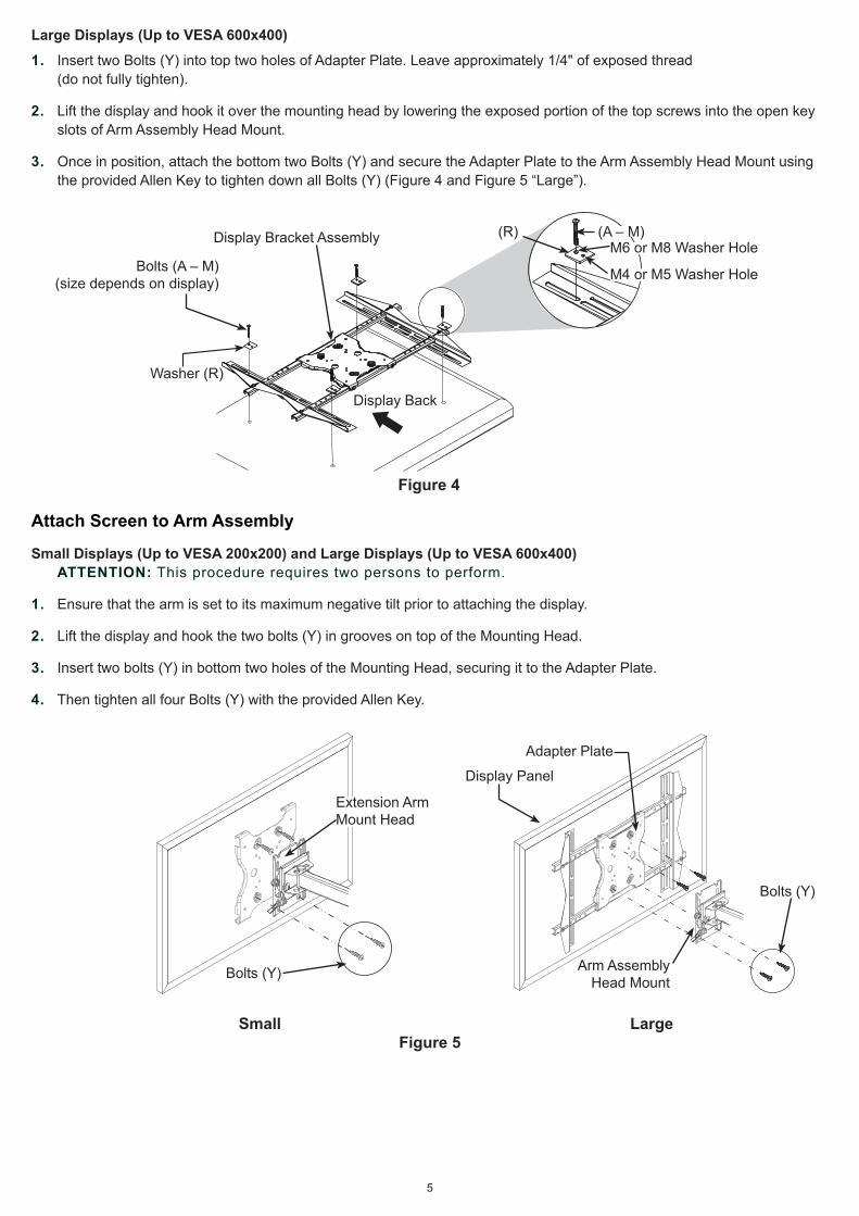
Large Displays (Up to VESA 600x400)
1. Insert two Bolts (Y) into top two holes of Adapter Plate. Leave approximately 1/4" of exposed thread (do not fully tighten).
2. Lift the display and hook it over the mounting head by lowering the exposed portion of the top screws into the open key slots of Arm Assembly Head Mount.
3. Once in position, attach the bottom two Bolts (Y) and secure the Adapter Plate to the Arm Assembly Head Mount using the provided Allen Key to tighten down all Bolts (Y) (Figure 4 and Figure 5 “Large”).
Figure 4
Attach Screen to Arm Assembly
Small Displays (Up to VESA 200x200) and Large Displays (Up to VESA 600x400)ATTENTION: This procedure requires two persons to perform.
1. Ensure that the arm is set to its maximum negative tilt prior to attaching the display.
2. Lift the display and hook the two bolts (Y) in grooves on top of the Mounting Head.
3. Insert two bolts (Y) in bottom two holes of the Mounting Head, securing it to the Adapter Plate.
4. Then tighten all four Bolts (Y) with the provided Allen Key.
Small Large
Figure 5
Display Bracket Assembly
Display Back
(R)
M4 or M5 Washer Hole
M6 or M8 Washer Hole(A – M)
Bolts (A – M)(size depends on display)
Washer (R)
Extension ArmMount Head
Bolts (Y)
Display Panel
Adapter Plate
Bolts (Y)
Arm AssemblyHead Mount
6
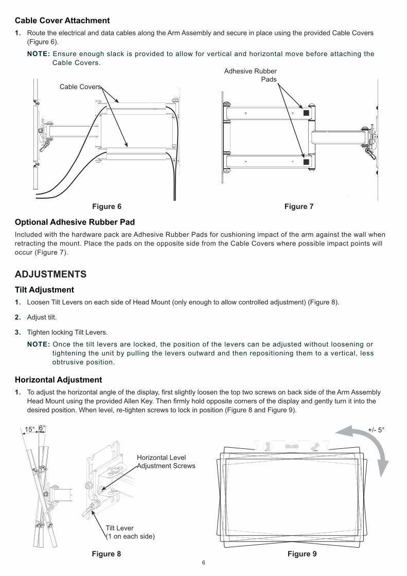
Cable Cover Attachment1. Route the electrical and data cables along the Arm Assembly and secure in place using the provided Cable Covers
(Figure 6).
NOTE: Ensure enough slack is provided to allow for vertical and horizontal move before attaching the Cable Covers.
Figure 6 Figure 7
Optional Adhesive Rubber PadIncluded with the hardware pack are Adhesive Rubber Pads for cushioning impact of the arm against the wall when retracting the mount. Place the pads on the opposite side from the Cable Covers where possible impact points will occur (Figure 7).
ADJUSTMENTSTilt Adjustment1. Loosen Tilt Levers on each side of Head Mount (only enough to allow controlled adjustment) (Figure 8).
2. Adjust tilt.
3. Tighten locking Tilt Levers.
NOTE: Once the tilt levers are locked, the position of the levers can be adjusted without loosening or tightening the unit by pulling the levers outward and then repositioning them to a vertical, less obtrusive position.
Horizontal Adjustment1. To adjust the horizontal angle of the display, first slightly loosen the top two screws on back side of the Arm Assembly
Head Mount using the provided Allen Key. Then firmly hold opposite corners of the display and gently turn it into the desired position. When level, re-tighten screws to lock in position (Figure 8 and Figure 9).
Figure 8 Figure 9
Cable Covers
Adhesive Rubber Pads
Horizontal LevelAdjustment Screws
+/- 5°15° 6°
Tilt Lever(1 on each side)
7
CONTACTING TECHNICAL SUPPORTPhone: (866) 838-5052
Email: [email protected]
LIFETIME LIMITED WARRANTY
Lifetime
Strong™ Mounts have a Lifetime Limited Warranty. This warranty includes parts and labor repairs on all components found to be defective in material or workmanship under normal conditions of use. This warranty shall not apply to products which have been abused, modified or disassembled. Products to be repaired under this warranty must be returned to Snap AV or a designated service center with prior notification and an assigned return authorization (RA) number.

150120-2300© 2015 STRONG