Embed Size (px)
Citation preview
�Stafsjö Valves AB. SE-618 95 Stavsjö, Sweden. Tel: +46 (0)11-39 31 00. Fax: +46 (0)11-39 30 67. [email protected] www.stafsjo.com
A Bröer Group company
Document: Data sheetProduct: SLVSize: DN 80 -DN 600 Issue: 6Issue date: 2009-�2-22
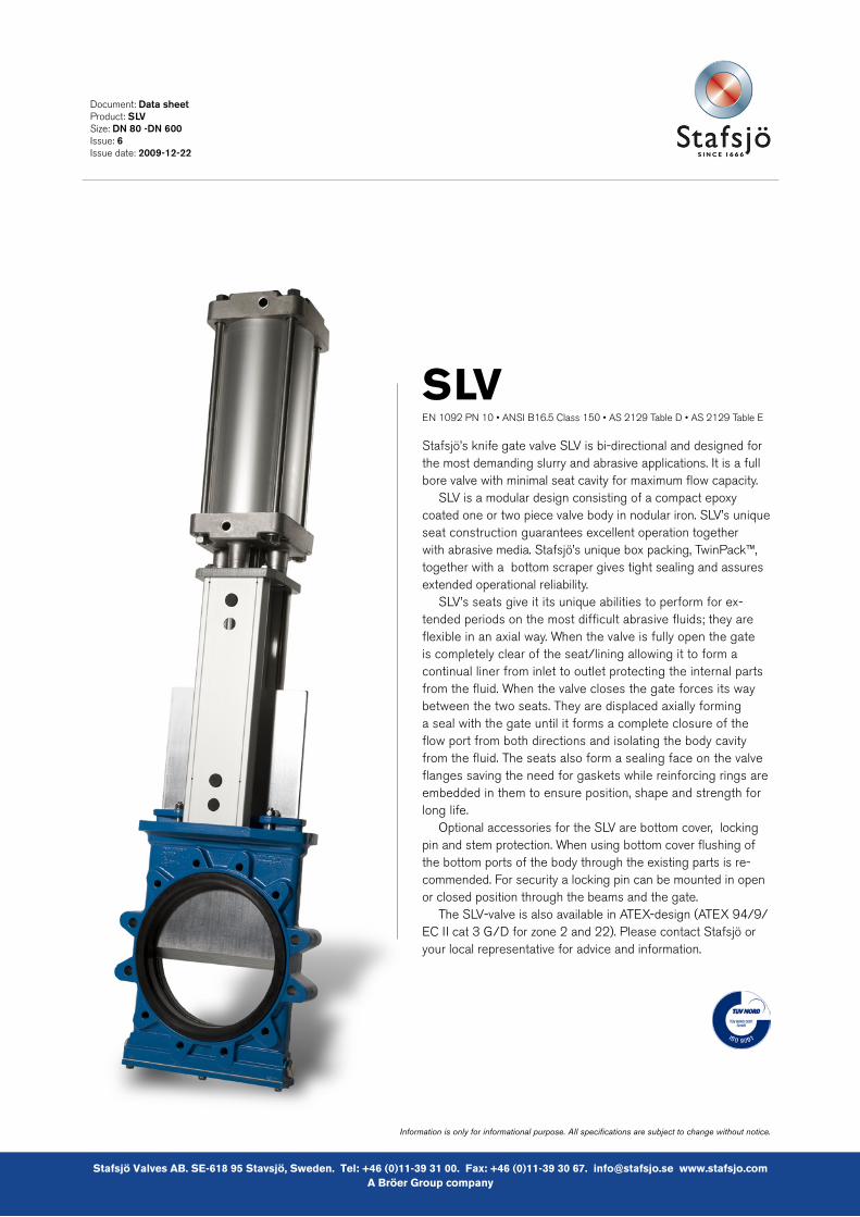
SLVEN 1092 PN 10 • ANSI B16.5 Class 150 • AS 2129 Table D • AS 2129 Table E
Stafsjö’s knife gate valve SLV is bi-directional and designed for the most demanding slurry and abrasive applications. It is a full bore valve with minimal seat cavity for maximum flow capacity.
SLV is a modular design consisting of a compact epoxy coated one or two piece valve body in nodular iron. SLV’s unique seat construction guarantees excellent operation together with abrasive media. Stafsjö’s unique box packing, TwinPack™, together with a bottom scraper gives tight sealing and assures extended operational reliability.
SLV’s seats give it its unique abilities to perform for ex-tended periods on the most difficult abrasive fluids; they are flexible in an axial way. When the valve is fully open the gate is completely clear of the seat/lining allowing it to form a continual liner from inlet to outlet protecting the internal parts from the fluid. When the valve closes the gate forces its way between the two seats. They are displaced axially forming a seal with the gate until it forms a complete closure of the flow port from both directions and isolating the body cavity from the fluid. The seats also form a sealing face on the valve flanges saving the need for gaskets while reinforcing rings are embedded in them to ensure position, shape and strength for long life.
Optional accessories for the SLV are bottom cover, locking pin and stem protection. When using bottom cover flushing of the bottom ports of the body through the existing parts is re-commended. For security a locking pin can be mounted in open or closed position through the beams and the gate.
The SLV-valve is also available in ATEX-design (ATEX 94/9/EC II cat 3 G/D for zone 2 and 22). Please contact Stafsjö or your local representative for advice and information.
Information is only for informational purpose. All specifications are subject to change without notice.
2
Document: Data sheetProduct: SLVSize: DN 80 -DN 600 Issue: 6Issue date: 2009-�2-22
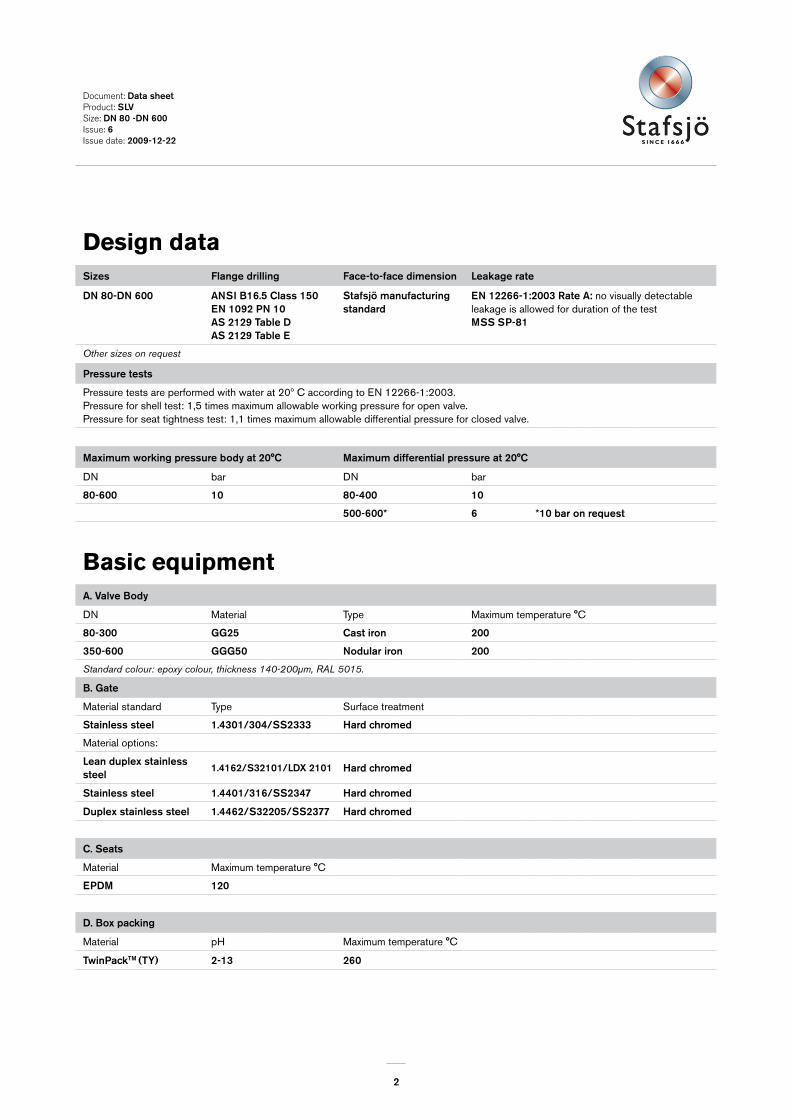
Design dataSizes Flange drilling Face-to-face dimension Leakage rate
DN 80-DN 600 ANSI B�6.5 Class �50EN �092 PN �0 AS 2�29 Table DAS 2�29 Table E
Stafsjö manufacturing standard
EN �2266-�:2003 Rate A: no visually detectable leakage is allowed for duration of the test MSS SP-8�
Other sizes on request
Pressure tests
Pressure tests are performed with water at 20º C according to EN 12266-1:2003.Pressure for shell test: 1,5 times maximum allowable working pressure for open valve.Pressure for seat tightness test: 1,1 times maximum allowable differential pressure for closed valve.
Maximum working pressure body at 20°C Maximum differential pressure at 20°C
DN bar DN bar
80-600 �0 80-400 �0
500-600* 6 *�0 bar on request
Basic equipmentA. Valve Body
DN Material Type Maximum temperature °C
80-300 GG25 Cast iron 200
350-600 GGG50 Nodular iron 200
Standard colour: epoxy colour, thickness 140-200µm, RAL 5015.
B. Gate
Material standard Type Surface treatment
Stainless steel �.430�/304/SS2333 Hard chromed
Material options:
Lean duplex stainless steel
�.4�62/S32�0�/LDX 2�0� Hard chromed
Stainless steel �.440�/3�6/SS2347 Hard chromed
Duplex stainless steel �.4462/S32205/SS2377 Hard chromed
C. Seats
Material Maximum temperature °C
EPDM �20
D. Box packing
Material pH Maximum temperature °C
TwinPackTM (TY) 2-�3 260
3
Document: Data sheetProduct: SLVSize: DN 80 -DN 600 Issue: 6Issue date: 2009-�2-22
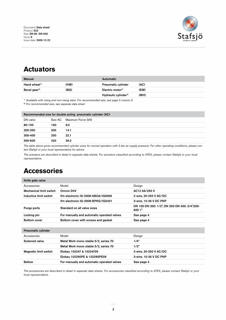
ActuatorsManual Automatic
Hand wheel�) (HW) Pneumatic cylinder (AC)
Bevel gear2) (BG) Electric motor2) (EM)
Hydraulic cylinder2) (MH)1) Available with rising and non-rising stem. For recommended size, see page 5 column E2) For recommended size, see separate data sheet
Recommended size for double acting pneumatic cylinder (AC)
DN valve Size AC Maximum Force (kN)
80-�50 �60 9.0
200-250 200 �4.�
300-400 250 22.�
500-600 320 36.2
The table above gives recommended cylinder sizes for normal operation with 5 bar air supply pressure. For other operating conditions, please con-tact Stafsjö or your local representative for advice.
The actuators are described in detail in separate data sheets. For actuators classified according to ATEX, please contact Stafsjö or your local representative.
AccessoriesKnife gate valve
Accessories Model Design
Mechanical limit switch Omron D4V AC�2 5A/250 V
Inductive limit switch ifm electronic IG-2008-ABOA/IG0006 2-wire, 20-250 V AC/DC
ifm electronic IG-3008-BPKG/IG540� 3-wire, �0-36 V DC PNP
Purge ports Standard on all valve sizesDN �00-DN 200: �/2”, DN 250-DN 400: 3/4”,500-600 �”
Locking pin For manually and automatic operated valves See page 4
Bottom cover Bottom cover with screws and gasket See page 4
Pneumatic cylinder
Accessories Model Design
Solenoid valve Metal Work mono stable 5/2, series 70 �/4”
Metal Work mono stable 5/2, series 70 �/2”
Magnetic limit switch Elobau �02247 & �0224709 2-wire, 20-250 V AC/DC
Elobau �02290PE & �02290PE09 3-wire, �0-36 V DC PNP
Bellow For manually and automatic operated valves See page 4
The accessories are described in detail in separate data sheets. For accessories classified according to ATEX, please contact Stafsjö or your local representative.
4
Document: Data sheetProduct: SLVSize: DN 80 -DN 600 Issue: 6Issue date: 2009-�2-22
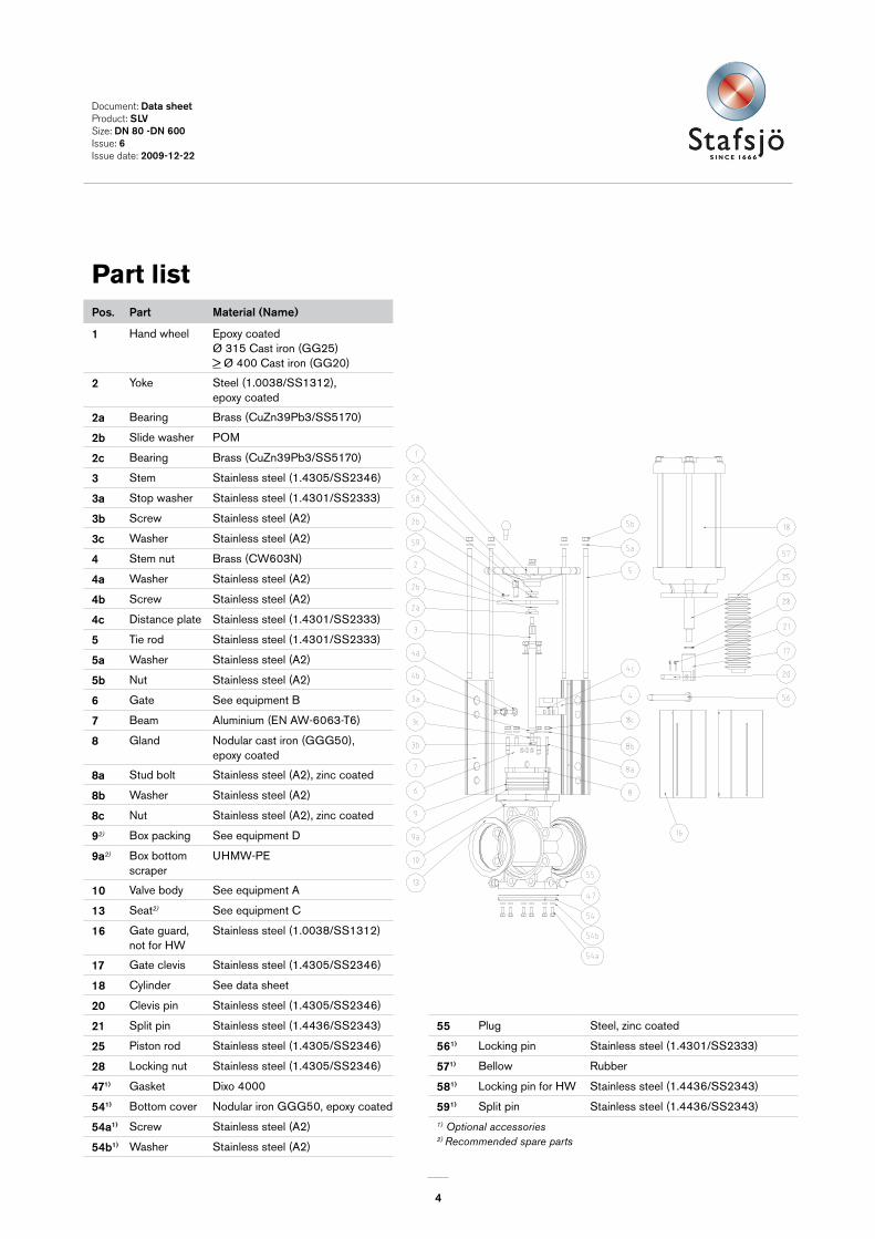
Part listPos. Part Material (Name)
� Hand wheel Epoxy coatedØ 315 Cast iron (GG25) > Ø 400 Cast iron (GG20)
2 Yoke Steel (1.0038/SS1312), epoxy coated
2a Bearing Brass (CuZn39Pb3/SS5170)
2b Slide washer POM
2c Bearing Brass (CuZn39Pb3/SS5170)
3 Stem Stainless steel (1.4305/SS2346)
3a Stop washer Stainless steel (1.4301/SS2333)
3b Screw Stainless steel (A2)
3c Washer Stainless steel (A2)
4 Stem nut Brass (CW603N)
4a Washer Stainless steel (A2)
4b Screw Stainless steel (A2)
4c Distance plate Stainless steel (1.4301/SS2333)
5 Tie rod Stainless steel (1.4301/SS2333)
5a Washer Stainless steel (A2)
5b Nut Stainless steel (A2)
6 Gate See equipment B
7 Beam Aluminium (EN AW-6063-T6)
8 Gland Nodular cast iron (GGG50), epoxy coated
8a Stud bolt Stainless steel (A2), zinc coated
8b Washer Stainless steel (A2)
8c Nut Stainless steel (A2), zinc coated
92) Box packing See equipment D
9a2) Box bottom scraper
UHMW-PE
�0 Valve body See equipment A
�3 Seat2) See equipment C
�6 Gate guard,not for HW
Stainless steel (1.0038/SS1312)
�7 Gate clevis Stainless steel (1.4305/SS2346)
�8 Cylinder See data sheet
20 Clevis pin Stainless steel (1.4305/SS2346)
2� Split pin Stainless steel (1.4436/SS2343) 55 Plug Steel, zinc coated
25 Piston rod Stainless steel (1.4305/SS2346) 56�) Locking pin Stainless steel (1.4301/SS2333)
28 Locking nut Stainless steel (1.4305/SS2346) 57�) Bellow Rubber
47�) Gasket Dixo 4000 58�) Locking pin for HW Stainless steel (1.4436/SS2343)
54�) Bottom cover Nodular iron GGG50, epoxy coated 59�) Split pin Stainless steel (1.4436/SS2343)
54a�) Screw Stainless steel (A2) 1) Optional accessories2) Recommended spare parts54b�) Washer Stainless steel (A2)
5
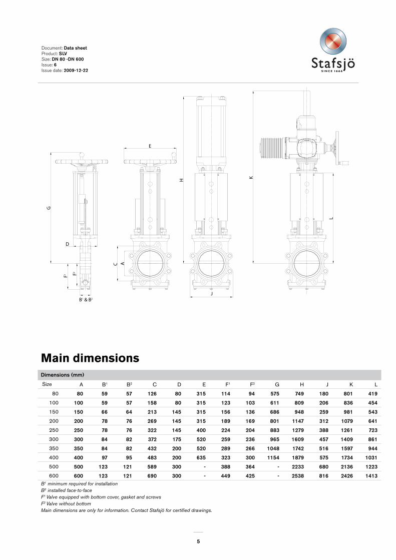
A B1 B2 C D E F1 F2 G H J K L
80 80 59 57 �26 80 3�5 ��4 94 575 749 �80 80� 4�9
100 �00 59 57 �58 80 3�5 �23 �03 6�� 809 206 836 454
150 �50 66 64 2�3 �45 3�5 �56 �36 686 948 259 98� 543
200 200 78 76 269 �45 3�5 �89 �69 80� ��47 3�2 �079 64�
250 250 78 76 322 �45 400 224 204 883 �279 388 �26� 723
300 300 84 82 372 �75 520 259 236 965 �609 457 �409 86�
350 350 84 82 432 200 520 289 266 �048 �742 5�6 �597 944
400 400 97 95 483 200 635 323 300 ��54 �879 575 �734 �03�
500 500 �23 �2� 589 300 - 388 364 - 2233 680 2�36 �223
600 600 �23 �2� 690 300 - 449 425 - 2538 8�6 2426 �4�3
E
AC
J
H
L
KD
B1 & B2
F1
G
F2
Document: Data sheetProduct: SLVSize: DN 80 -DN 600 Issue: 6Issue date: 2009-�2-22
Main dimensions Dimensions (mm)
Size
B1 minimum required for installationB2 installed face-to-faceF1 Valve equipped with bottom cover, gasket and screwsF2 Valve without bottomMain dimensions are only for information. Contact Stafsjö for certified drawings.
6
2ß
ß
Document: Data sheetProduct: SLVSize: DN 80 -DN 600 Issue: 6Issue date: 2009-�2-22
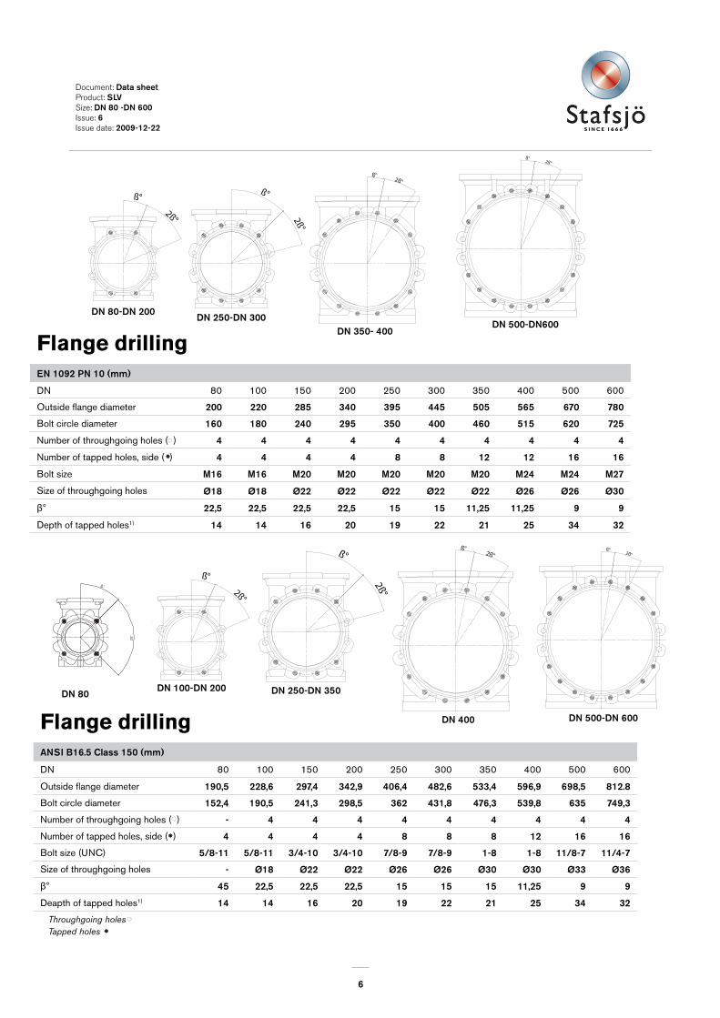
Flange drillingANSI B�6.5 Class �50 (mm)
DN 80 100 150 200 250 300 350 400 500 600
Outside flange diameter �90,5 228,6 297,4 342,9 406,4 482,6 533,4 596,9 698,5 8�2.8
Bolt circle diameter �52,4 �90,5 24�,3 298,5 362 43�,8 476,3 539,8 635 749,3
Number of throughgoing holes ( ) - 4 4 4 4 4 4 4 4 4
Number of tapped holes, side ( ) 4 4 4 4 8 8 8 �2 �6 �6
Bolt size (UNC) 5/8-�� 5/8-�� 3/4-�0 3/4-�0 7/8-9 7/8-9 �-8 �-8 ��/8-7 ��/4-7
Size of throughgoing holes - Ø�8 Ø22 Ø22 Ø26 Ø26 Ø30 Ø30 Ø33 Ø36
Ⱐ45 22,5 22,5 22,5 �5 �5 �5 ��,25 9 9
Deapth of tapped holes1) �4 �4 �6 20 �9 22 2� 25 34 32
Throughgoing holes
12121010
Ø30Ø26Ø26Ø22Size of throughgoing holes in flangeB
2ß°
ß°
2ß°
ß°
Bolt size
Screw length
ß°
2ß°2ß°
ß°
15412710278
and the estimated thickness of the gasket.
1) Add the values in the table with the thickness of the pipe flanges, the washers
1) 2217Screw lengths 3025911,2511,25 9ß°
=Throughgoing holes=Tapped holes
Outside flange diam (mm) 780565505 670
600400350 500Size (DN)
B
725620
8M27
8M24
515460
6M24
6M20Bolt size
No. of tapped hole/side. ( )No. of throughgoing bolts ( )Bolt circle diameter (mm)
Tapped holes
12121010
Ø30Ø26Ø26Ø22Size of throughgoing holes in flangeB
2ß°
ß°
2ß°
ß°
Bolt size
Screw length
ß°
2ß°2ß°
ß°
15412710278
and the estimated thickness of the gasket.
1) Add the values in the table with the thickness of the pipe flanges, the washers
1) 2217Screw lengths 3025911,2511,25 9ß°
=Throughgoing holes=Tapped holes
Outside flange diam (mm) 780565505 670
600400350 500Size (DN)
B
725620
8M27
8M24
515460
6M24
6M20Bolt size
No. of tapped hole/side. ( )No. of throughgoing bolts ( )Bolt circle diameter (mm)
Flange drillingEN �092 PN �0 (mm)
DN 80 100 150 200 250 300 350 400 500 600
Outside flange diameter 200 220 285 340 395 445 505 565 670 780
Bolt circle diameter �60 �80 240 295 350 400 460 5�5 620 725
Number of throughgoing holes ( ) 4 4 4 4 4 4 4 4 4 4
Number of tapped holes, side ( ) 4 4 4 4 8 8 �2 �2 �6 �6
Bolt size M�6 M�6 M20 M20 M20 M20 M20 M24 M24 M27
Size of throughgoing holes Ø�8 Ø�8 Ø22 Ø22 Ø22 Ø22 Ø22 Ø26 Ø26 Ø30
Ⱐ22,5 22,5 22,5 22,5 �5 �5 ��,25 ��,25 9 9
Depth of tapped holes1) �4 �4 �6 20 �9 22 2� 25 34 32
12121010
Ø30Ø26Ø26Ø22Size of throughgoing holes in flangeB
2ß°
ß°
2ß°
ß°
Bolt size
Screw length
ß°
2ß°2ß°
ß°
15412710278
and the estimated thickness of the gasket.
1) Add the values in the table with the thickness of the pipe flanges, the washers
1) 2217Screw lengths 3025911,2511,25 9ß°
=Throughgoing holes=Tapped holes
Outside flange diam (mm) 780565505 670
600400350 500Size (DN)
B
725620
8M27
8M24
515460
6M24
6M20Bolt size
No. of tapped hole/side. ( )No. of throughgoing bolts ( )Bolt circle diameter (mm)
DN 400
DN 350- 400
ß°2ß°
ß°2ß°
ß°
2ß°
ß°
2ß°
DN 80-DN 200DN 250-DN 300
ß°2ß°
DN 500-DN600
2ß
ß
DN 80DN �00-DN 200 DN 250-DN 350
DN 500-DN 600
ß°2ß°
ß°2ß°
ß°
2ß°
ß°
2ß°
ß°
2ß°
ß°
2ß°
ß°
2ß°
ß°2ß°
ß°2ß°
ß°
2ß°
ß°
2ß°
ß°
2ß°
ß°
2ß°
ß°
2ß°
ß°2ß°
7
DN 80-DN �00
DN �50-DN 250DN 300-DN 400
ß°2ß°
DN 500-DN 600
ß
2ß
ß°2ß°
ß°
2ß°
ß°
2ß°
ß°
2ß°
ß°
2ß°
DN 250-DN 400 DN �00-DN 200
DN 80
2ß°
ß°
2ß
ß
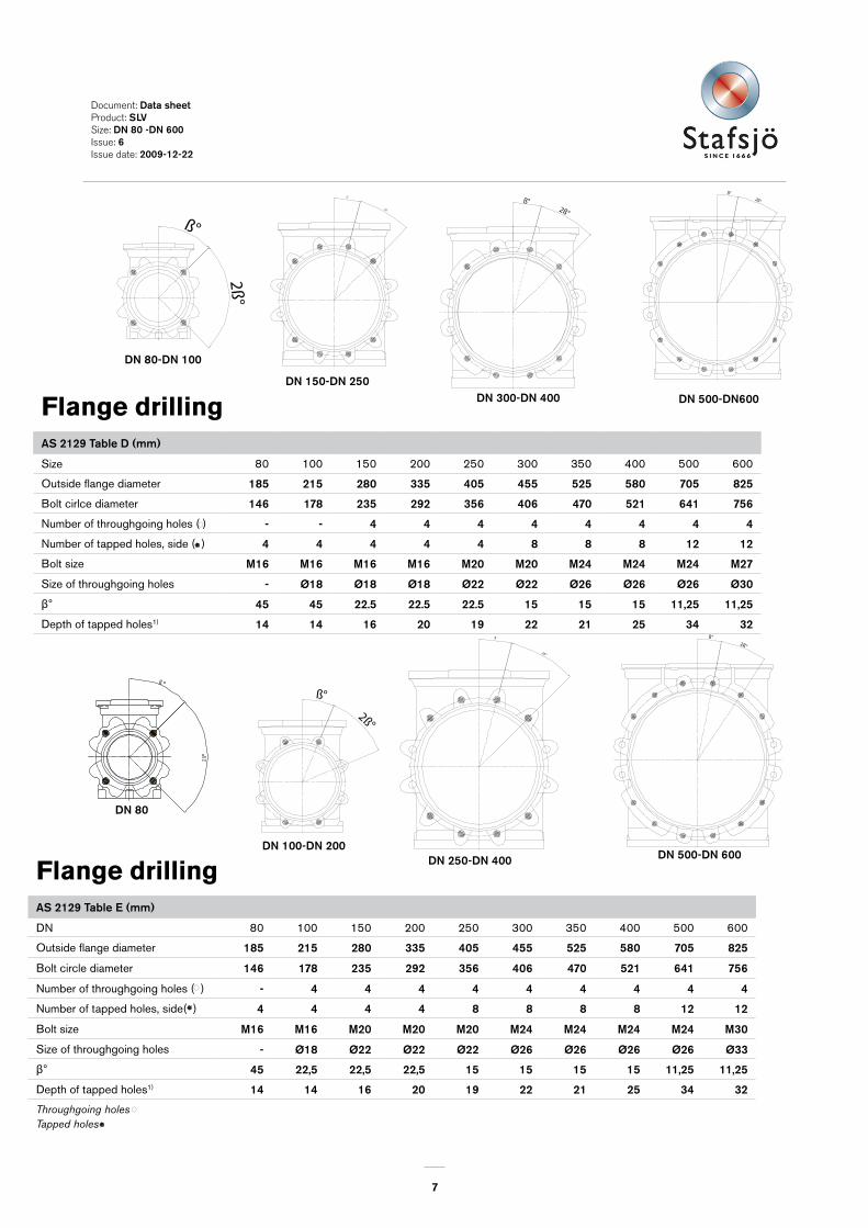
Document: Data sheetProduct: SLVSize: DN 80 -DN 600 Issue: 6Issue date: 2009-�2-22
Flange drillingAS 2�29 Table D (mm)
Size 80 100 150 200 250 300 350 400 500 600
Outside flange diameter �85 2�5 280 335 405 455 525 580 705 825
Bolt cirlce diameter �46 �78 235 292 356 406 470 52� 64� 756
Number of throughgoing holes ( ) - - 4 4 4 4 4 4 4 4
Number of tapped holes, side ( ) 4 4 4 4 4 8 8 8 �2 �2
Bolt size M�6 M�6 M�6 M�6 M20 M20 M24 M24 M24 M27
Size of throughgoing holes - Ø�8 Ø�8 Ø�8 Ø22 Ø22 Ø26 Ø26 Ø26 Ø30
Ⱐ45 45 22.5 22.5 22.5 �5 �5 �5 ��,25 ��,25
Depth of tapped holes1) �4 �4 �6 20 �9 22 2� 25 34 32
Flange drillingAS 2�29 Table E (mm)
DN 80 100 150 200 250 300 350 400 500 600
Outside flange diameter �85 2�5 280 335 405 455 525 580 705 825
Bolt circle diameter �46 �78 235 292 356 406 470 52� 64� 756
Number of throughgoing holes ( ) - 4 4 4 4 4 4 4 4 4
Number of tapped holes, side( ) 4 4 4 4 8 8 8 8 �2 �2
Bolt size M�6 M�6 M20 M20 M20 M24 M24 M24 M24 M30
Size of throughgoing holes - Ø�8 Ø22 Ø22 Ø22 Ø26 Ø26 Ø26 Ø26 Ø33
Ⱐ45 22,5 22,5 22,5 �5 �5 �5 �5 ��,25 ��,25
Depth of tapped holes1) �4 �4 �6 20 �9 22 2� 25 34 32
Throughgoing holesTapped holes
12121010
Ø30Ø26Ø26Ø22Size of throughgoing holes in flangeB
2ß°
ß°
2ß°
ß°
Bolt size
Screw length
ß°
2ß°2ß°
ß°
15412710278
and the estimated thickness of the gasket.
1) Add the values in the table with the thickness of the pipe flanges, the washers
1) 2217Screw lengths 3025911,2511,25 9ß°
=Throughgoing holes=Tapped holes
Outside flange diam (mm) 780565505 670
600400350 500Size (DN)
B
725620
8M27
8M24
515460
6M24
6M20Bolt size
No. of tapped hole/side. ( )No. of throughgoing bolts ( )Bolt circle diameter (mm)
ß°2ß°
ß°2ß°
ß°
2ß°
ß°
2ß°
ß°
2ß°
ß°
2ß°
ß°
2ß°
ß
2ß
2ß°
ß°
DN 500-DN600