Embed Size (px)
Citation preview

SolarRoofs.com, Inc. Wholly owned by ACR Solar International Corp.
5840 Gibbons Dr. Suite G Carmichael, CA 95608 (916) 481-7200
“Skyline” Closed Loop System 4 Systems 4 using 10-01 or 20-01 Collectors
Note: “Skyline” was Formerly “Fireball”
INSTALLATION MANUAL August, 4, 2008
The solar collectors described by this manual, when properly installed and maintained, meets or exceeds the minimum “OG-100 standards established by the SRCC. This certification does not imply endorsement or warranty of this product by SRCC.
“The solar collectors described by this manual, when properly installed and maintained, meets the minimum standards established by the Florida Solar Energy Center, in accordance with Section 377.705, Florida Statutes. This certification does not imply endorsement or warranty of this product by the Florida Solar Energy Center or the state of Florida.”
CONGRATULATIONS!
Thank you! You have just purchased the easiest to install active solar water heater made! We have worked on every detail to assure you that the “Skyline” water heater will completely satisfy you in its high level of performance and dependability.
Table of Contents SUBJECT SECTION Tools and Materials………………………………………………………………………1.0. Systems, Components and Options…………………………………………………..2.0. Specifications and Schematics………………………………………………………...2.1. Important Notes……………………………………………………………………………2.2. Collector Location, Orientation and Tilt………………………………………………3.0. Overview of the Basic Installation Steps………………………………………….….4.0. Assembling the Collector (split kits only)…………………………………………….5.0. Collector Installation……………………………………………………………………..6.0. Determining the Best Pipe Run…………………………………………………….…..7.0. Making Line Connections……………………………………………………………….8.0. Tank Connections………………………………………………………………………...9.0. Control Component Details…………………………….……………………………...10.0. Questions and Answers………………………………………………………………..11.0. Certifications……………………………………………………………………………..12.0.
PLEASE CALL SolarRoofs.com WITH QUESTIONS: Toll Free USA Technical Install Help Number: (888) 801-9060
WE WELCOME YOUR COMMENTS! We have endeavored to make the Skyline 2001 installation instructions complete and easy to use. We are always looking to make them better and we welcome your comments and suggestions!

Note: References to System 5 include system 4 with the significant difference being that system 5 is always 12 Volt and System 4 is usually 110 Volt. Actual items may vary from pictures. System 4 is SolarRoofs.com’s universal Closed Loop system with many options and variations possible. The standard Rheem Tank connections are the same.
BEFORE STARTING INSTALLATION PLEASE CAREFULLY READ THIS ENTIRE MANUAL FIRST!
Remember! A Collector in the Sun Can Be Very Hot – Cover It To Prevent Burns From Hot Copper Tubing and Very Hot Fluid Coming Out of the Tubes.
As the collector has some sharp metal edges and corners, use caution when handling the collector.
ALWAYS USE COPPER TUBING, NEVER PEX OR OTHER PLASTIC TUBING AS THEY MAY BURST FROM STAGNATION TEMPERATURES.
This Installation Manual and assumes good technical experience and ability.
The Skyline System 4 can be installed in straightforward situations by two experienced people in less than six hours.
With no experience, the installation will probably take eight to twelve hours, with added complications, like a longer pipe run or two stories, taking longer.
1.0. Tools and Materials
ITEMS SUPPLIED BY SOLARROOFS.COM:
• Collectors, with mounting rails, Ell brackets, U Center brackets and Solar Feed and Return line adapters • Coin Vent, Pressure Relief Valve, copper adaptor • 110 Volt Differential Controller with 2 sensors, one for the collector, and one for the tank or optional PV panel • Storage Tank Heat Exchanger brass connections with Expansion tank, Pressure Gauge, “Floating Ball” Check Valve. • 110 Volt Pump and connections, or optional 12 Volt Pump and connections. • 50’ 1/2” outside diameter copper solar loop lines. • Solar loop installation parts kit including miscellaneous parts, wires, fittings, screws, nuts, bolts, etc., • All hardware, two roof boots, 6' high temp. insulation. • Installation Manual, Operation and Maintenance Manual and Stickers. • Optional are Mixing Valve and Temperature Gauges TOOLS AND MATERIALS NEEDED (to connect to existing water heater):
Overview: Everyday homeowner tools are all that are needed to assemble and install the Skyline solar loop.
Tools and Materials Needed: • For compression unions, 2 large adjustable wrenches and/or wrench set • Min 18” “Monkey Wrench (best to have 2) • Teflon tape (1/2" wide to seal threaded fittings use 6 turns). • Quality Pipe Sealant (to seal face of brass union ends). • Ladder(s) (for roof and for access to attic as needed). • Tape measure, Marking pencil, crayon or chalk (to mark rafters and holes on roof) • Chalk for marking roof and Snap Line. • 1 1/2" inch wood bit for roof penetrations (for feed and return lines through roof). • 7/16" socket with ratchet and 6" extension. (a powerful drill with adapter is desirable for quickly driving lags). • 1/4” nut driver on high speed drill (to drive 1/4" self taping screws into collector). • Caulking gun with quality Polyurethane or Silicone roofing caulk (to fill lag holes and seal flashing to prevent leaks). • 3/4” or ½” wall, 7/8’ ID (about 12 feet) and 5/8” ID high temperature open cell pipe insulation for inside piping.

2.0. The following Systems, Components and Options are
Wholly or Partly Covered in this Manual Note: This manual covers 20-01 collector installation, the 10-01 collector will soon be OG100 approved for use with this system
• System : Complete 10 or 20 Square Foot , 20” x 6’ or 12’ Solar Panels with mounting kit and Rails, 110 Volt or optional 12 Volt Circulator, 110 Volt Differential Controller with 2 sensors, one for the collector, and one for the tank or optional PV + Complete Rheem Double Wall Heat Exchanger Tank Connections. 25' of wire, 50’- 1/2" OD Copper connecting line, all line connections, Collector Air Vent and Pressure Relief Valve, 2 Temperature Gauges, Mixing Valve, Install Kit, full instructions, Owners Manual. Includes Expansion Tank and all Connections for heat exchanger tank or external heat exchanger (Power Rod or other) 81V080HE1 TANK NOT SUPPLIED.
==================================================================================================== Tilt Kit (option) Tilts collectors approximately 18 degrees from existing roof angle, Other angles available on request. Tilt kits are used when a better winter angle is desired on a low pitch roof or to “re-orientate” panels to face south by running the panels up and down an East or West facing roof. See Special Instructions. Single Panel: Collector kit with 3 Modified 24” rails with 6” legs and hardware: (Option Code /#TK01) Double panels: Collector kit 3 - 4’ 1” x 1” Aluminum Rails with 12” legs and hardware: (Option Code /#TK02) Tripple panels: Collector kit 3 - 6’ 1” x 2” Alum. Rails with 24” legs and hardware: (Option Code /#TK03)
Standard Color (Default): Musket Brown (C101)
Free Optional Color: Dove/Old Town (Medium) Gray (C109) - Note: This is a no cost option.
Optional Colors Include: Colonial (light) Gray (CO102), Tahoe Blue (COl03), Colonial Red (COl04), Forest Green (COl05), White (COl06), Buckskin Brown (CO107), Beaver (medium) Brown (CO108), C.B. (medium) Blue (CO110), Spanish Green (CO111), Storm/Slate (dark) Gray (CO112), Royal Brown (CO113), Ivory (CO114), Sea Blue (CO115), Leaf Green (CO116), Pebblestone Clay (CO117), Woodbeige (CO118), Peach (great on many light orange tile roofs) (CO119), Almond (CO120), Black (CO121), Adobe Tan (CO121), Classic Cream (CO122), Bronze (CO123), Heritage Cream (CO124), Marine Green (CO125).
Components ( for individual purchase):
MVWA, Watts Mixing Valve:
QF34, Quad Flow Diverter
TR50, 50 foot roll of 3/8" ID, 1/2" OD soft copper tubing with 2 compression unions
D571, Laing D5 12V - 24 V Circulator:
PV10, 10 Watt 12V Panel With Mounting Hardware:
PV20, 20 Watt 12V Panel With Mounting Hardware:
PV20, 30 Watt 12V Panel With Mounting Hardware:
PR15, 150 Pound Pressure Relief Valve:
CV01, Floating Ball Check Valve:
H180, 180 F High Temperature snap switch, open 180 F, close 140 F, place on cold in:

2.1. Skyline System 4 Solar Water Heater Specifications
COLLECTOR (Panel) Trim & Frame Materials: Finished 27 mil Aluminum Trim and Frame = Total 54 mil (1.37 mm). Insulation: Bottom: 1" (2.54 cm) Foil Faced Celotex Absorber Material: “Black Crystal” coated - all Copper with compression unions. Glazing: . 236” (6.0 mm) Twinwall Polycarbonate UV Treated Dimension / Weight: 2001-144.3”x 20.”x 3” 38 lb (3.67 m x 0.51 m x 0.076 m 17.24 Kg) 18.4 Net s/f (1.71 m2) Fluid Capacity: . .3 Gallons Recommended Flow Rates: .20 to .35 GPM (0.946 to 1.324 L/min) Maximum Working Pressure: 150 PSI (10.21 atm). Maximum Stagnation Temp: 250 °F (121.11 °C). Heat Transfer Fluid: Potable water Standard Components: 3 Mounting rails, mounting brackets, tech screws and lags Color: Musket Brown (Cl01 – default color) or Dove/Old Town Gray (C109) + optional colors
System 4: DIFFERENTIAL CONTROL Type: Independent Energy CM30 or Equal Sensors: Two 10K Sensors with wire Turn on Differential: 8 - 24 °F (Ave. set 12 °F) Turn off Differential: 4 °F (fixed) Recirculate on: 38°F (3.33 °C) Storage High Limit: 110 – 230 °F Set at 180 °F (82.2 °C) Power requirements: 105-120VAC, 50/60hz, Output power: 115VAC, 1/3HP (248.56 W)
Optional PV (Photovoltaic) POWERED CIRCULATOR (Optional) PV Panel: 10 - 50 Watt, 12volt DC with switch. Circulator: 12 Volt - 10 – 50 Watt.
PUMP 115 Volt AC Taco 006 Bronze or equal CONNECTING LINES, INSULATION (standard) Tubing: 1/2” (12.7 mm) OD copper - 50’ (15.24 m) Copper and Brass Fittings Insulation, High Temperature (6’ (1.83 m) supplied): 1/2” (12.7 mm), 1/2” (13 mm) wall
ALWAYS USE COPPER TUBING, NEVER PEX OR OTHER PLASTIC TUBING AS THEY MAY BURST FROM STAGNATION TEMPERATURES.
TUBING CONNECTION METHODS (standard) Type: Brass Union, Compression.
STORAGE TANK - Rheem / Rudd / Richmond Model Number: 81V080HE1 (Not Supplied) 80 Gallon Tank with In Tank Double Wall Heat Exchanger. Fluid Used: Propylene Glycol (Sierra) Components Supplied: Expansion Tank, one floating ball check valve, Temperature Gauge, fill, drain, and pressure relief valves. CONTROL Type: 110 Volt Differential Controller with 2 sensors, one for the collector, and one for the tank
Although we will make every effort to give notice, Specifications and prices subject to change without notice.

System 4 set up for internal Heat Exchanger Tanks (with 3/4” female fittings )
Rheem/ Rudd,
Richmond or other
Heat Exchanger
storage tank
Loop charge valve V1
Loop charging V3 isolation valve
Loop charge drain valve V2
150 PSI Pressure Relief Valve Coin Vent
Differential Control with digital temperature readouts(versions may be 12 volt with 110 Volt transformer)
Domestic cold in
Optional Mixing Valve
Tank Drain
Domestic hot out
10-01 or 20-01 Skyline Collectors: 30, 40, 60, or 80 S/F
Floating Ball Check valve
Tank Pressure Temperature Relief Valves
Cold shutoff
110 V pump(versions may be 12 Volt)
Expansion Tank
Solar Loop Pressure Gauge
Heat Exchanger
Use 1/2” OD soft copper tubing with brass compression couplings
Roof Boots
3/4” female fittings

Please Note: SolarRoofs has improved its system and some pictures will not be visually accurate but show all the components included. Most copper fittings have been replaced with Brass. More visually accurate pictures will be included in their sections.

2.2. IMPORTANT NOTES:
BEFORE STARTING INSTALLATION PLEASE CAREFULLY READ THIS ENTIRE MANUAL FIRST!
CHECK WITH YOUR LOCAL BUILDING DEPARTMENT FOR CODE COMPLIANCE FOR
THE INSTALLATION OF YOUR SOLAR WATER HEATING SYSTEM.
In all cases where a firewall (drywall) is penetrated, it is important to seal the hole. A good general rule is to always fill in and seal around all holes made for
solar lines to prevent heat loss and to maintain fire stops.
Properly support all piping according to local code. As a rule, support copper pipe every 6’.
SAFETY FIRST!!
USE CAUTION!!! Do not attempt to self-install without help if you have ANY back or physical limitations!!!
GENERAL WARNINGS: Remember! A Collector in the Sun Can Be Very Hot – Cover it to Prevent
Burns From Hot Copper Tubing and Very Hot Fluid Coming Out of the Tubes.
As the collector has some sharp metal edges and corners, use caution when handling the collector.
ALWAYS USE COPPER TUBING, NEVER PEX OR OTHER PLASTIC TUBING AS THEY MAY BURST FROM STAGNATION TEMPERATURES. This manual assumes that the installer has good mechanical experience and can confidently use hand tools, building materials and adhere to safe building and installation practices. Do not install this system alone without someone knowing where you are and what you are doing at all times. SolarRoofs.com does not assume responsibility for any loss, or injury directly or indirectly, associated with the installation of this system. SolarRoofs systems are easy to install; however, problems resulting from a failure to correctly install the system according to the following instructions and to maintain it according to the operation and maintenance manual are not covered by the warranty.

3.0. COLLECTOR LOCATION, ORIENTATION AND TILT
Your solar water system will be providing savings for your family for decades to come. Because the sun rises in the east, crosses over the horizon on the south and sets in the west, you want your collector to face as much to the south as possible. Your system needs the most sun it can get! As long as the collector angle (known as tilt) is at least 14 degrees up from horizontal, (a typical roof angle is 22 to 28 degrees) additional tilt usually has little effect on total year round performance. The exception is in areas with very sunny winters (as in most areas of Colorado) where a higher angle, (facing the collector more directly into the winter sun) can help year round performance. In most areas with heavy winter overcast, a solar collector's orientation on a low pitched roof can face anywhere from 45 degrees east to west of south without losing more than 8% of the energy it would have
produced if it were facing directly south. At 90 degrees east to west of south the loss is closer to 20%. Exceptions include easterly facing systems in areas with a lot of morning fog and clear afternoons where south facing or west facing would be much better. The opposite can be true if sunny mornings are very often followed by rainy afternoons. Take these facts, and your tubing run to the tank, (see 7.0.) into consideration when locating your collector and consult with us if you have any questions. ROOF CONDITION: The condition of your roof should be good although one of the features of Skyline system is that removing and replacing the collector is relatively easy for re-roofing.

OVERVIEW - THE BASIC INSTALLATION STEPS:
THE BASIC INSTALLATION STEPS (3 to 8 hours required to install, depending on situation and experience) 1. Unpack collector, check for any damage and for any missing parts. 2. Tubing run to tank from collector determined - (See 7.0.). Collector placement on roof located, rafters located and marked, end mounting rails with brackets lagged and sealed into rafters, collector placed into mounting rail brackets, center mounting rail and brackets placed, lagged and sealed into rafter, mounting rail brackets screwed into collector. 3. Collector compression unions connecting air vent, pressure relief valve and components installed, two 1 1/2" holes drilled into roof for hot feed and cool return lines. Shingles trimmed and "Roof Boots" installed under shingles and into holes. PV panel installed.
4.0.
4.Collector cool feed (bottom compression union) and hot return lines (top compression union) installed through roof boots to tank area. PV wire connected and run to water heater area. Insulation partly installed before tubing connections are made. PV panel installed. 5. Water Heater Element turned off, water drained, lower drain removed, Rheem 80 gallon Heat Exchanger tank installed with Mixing Valve. Water lines connected including installation of the Mixing valve. Brass Solar lines with valves connected to heat exchanger top and bottom. Pump, pressure gauge and expansion tank installed. Collector cool feed (from pump) and hot return lines connected by compression union. 6. Water heater refilled, solar loop purged of air, pump wired to PV panel. Glycol loop filled, finish insulating lines, Fill Tank, Element turned back on.
5.0. ASSEMBLING THE COLLECTOR (See Supplemental “Split Kit” Addendum)
COLLECTOR INSTALLATION 6.0.
BE SECURE AND USE CARE!!! Good procedure suggests that you always secure your ladder to the gutter so it does not slip. Place blocks in the gutter so the weight of the ladder does not crush the gutter. Protect the surface of the gutter with a cloth to prevent marks. WALKING ON THE ROOF: Use soft sole shoes. Walk in the center of the shingle to prevent knocking off the brittle ends of the shingles. This care will keep the roof in good condition and prevent dangerous ball bearing like gravel and tar balls from making the roof treacherous. Know how to walk on your roof if it is a special type such as Tile or Metal, ask your roofer or ask us. For example, stepping in the center of most Tile roof shingles will break them. Always put your weight on the last two (overlapping) inches of the tile and away from the side that overlaps the next tile (to avoid chipping off the delicate vertical overlap strip). On some shingles, such as “Fire-Free”, or shake, more
damage is done stepping on the end than in stepping on the center. Shake roofs are usually easy to walk on but use care on shake roofs to not crack or break off brittle shakes. Shake roofs, as well as most roofs, can be treacherous when wet. As the 20-01 collector is 12’ long, it is important to place the line connection end so it is the shortest distance from the storage tank. The collector can be flipped either way to be closest to your storage area. Remember that the feed line from the pump goes to the bottom collector connection and the hot return goes to the top collector connection as shown in the diagrams. On an average, low pitch single story roof, one able person can safely install the Skyline collector. Do not install this system alone, be sure someone knows where you are and what you are doing at all times. The 12 foot long 20-01 collector weighing under 38 pounds, makes it an ideal size and weight for one person to lean against the roof or gutter, go up the ladder and simply pick up the collector and pull up onto the roof.
Collector installation Components: Note 10-01 collectors will have 2 sets of collector brackets instead of 3 ALWAYS USE COPPER TUBING, NEVER PEX OR OTHER PLASTIC TUBING AS THEY MAY BURST FROM STAGNATION TEMPERATURES.
It is important to not over-tighten these fittings.
Spraying a little silicone on the threads is helpful.
A couple of turns of Teflon tape around the ring helps make sealing easier.
½’ OD Compression Union and Ell Compression Ell Nut with Ring Inside
Tube must extend beyond ring about ¼” and bottom out inside the compression body before tightening nut
Nut, Ring, Union Body
PV Parts Bag contains PV switch Brackets and hardware. See 9.0, Control Component Detail.
Roof Kit contains: Mounting Ells and washers, 3.5 or 4” Lags, Center U Brackets for 2 or more collectors, Color coded Tec Screws for securing Ell brackets and U brackets to collector, Low profile Roof Boots.
Plumbing Kit:
50’ of ½” OD Copper, Pressure Relief, Coin (air) vent, Soldered adaptor, Compression fittings, 1 Compression union body per extra collector, 2 compression unions to connect tubing to tank.
Important Instructions Regarding Installing Compression Unions

Collectors mount horizontally and Collector Mounting Rails go as shown below.
Two Collector 20-01 Top View (10-01 collectors use 2 rails about 1’ in from the ends)
The Diagram above is a top view of two collectors installed together showing: 1. Two 20" x 12' Collectors mounted with connections to the right.
2. The Mounting Rails with Mounting Brackets (3 rails and 6 Mounting Brackets plus 3 Quick Connect Clips (QCC) per additional collector set (6.), 3 two panel rails, 6 Mounting Brackets and 3 QCCs shown in this diagram).
2A. Mounting Rail Lag holes top and bottom. 3. The "Hot Out" Collector connection going to the storage tank. 4. The between Collector connection. 5. The "Cold In" Collector connection from the storage tank. 6. The Quick Connect Clip bolts to the mounting rail here with the tabs overlapping the top of the collector. 7. Collector Glazing (Lexan) 8. Collector trim sections.
2 7 8 3
4
5
6
1
1
2A
Above: Allowing from 14” to 2’ for collector overhang, find and mark Rafters for the Three Collector Rails, (shown in this picture are 3 rails for 3 collectors) Use a chalk line to get the 3 rails even at the bottom. Get the center rail as close to center between the end rails as possible. Using a hammer to “Sound Out” the rafters usually finds the rafters. If not, use a feeler bit (long small drill) to drill through the roof from the inside, just beside the rafter. Be sure to squeeze calk into all holes to seal them! Pre-Drill the bottom holes for the 2 end rails (which will be about 8’ apart – you can use the lag itself to “pre drill”), squeeze Caulk into Lag Hole, Place end mounting rail with mounting bracket and washer over hole (above left). Drive Lags into holes but do not tighten. Carefully place the center rail along the chalk line, repeat the proceedure for the end rails. Install the upper lags using the same proceedure. Note: )ne and two collector systems have lags at the top and bottom of the rails. Three and four collectors use a center lag at the center of the end rails only. Other Quick connect clips use a carrage bolt.

2001 Side View
The above Diagram shows a side view of the Collector installed on the roof and shows:
(Refer to Color Pictures for Details of Ell Brackets) 1. Side view of a Collector. 2. Mounting Rails (3 per 20-01 collector). 2A. Mounting Rail Lag. 2B. Roof sheathing.
2C. Roof Rafter. 3. Collector feed or return connection. 8. Collector Trim.
LAGS AND RAFTERS:
For maximum strength, you want your mounting rail (2) lags (2A) to go into rafters. After locating the best area for the collector, “sound out” the roof for the rafters with a hammer and mark the rafter centers with chalk. On thick roofs, such as shake, you may need to drill a small hole from the underside of the roof next to the rafter to locate it from the roof and use measurements from thereon. On thin composition roofs, a good stud finder can be very helpful in finding the center of the studs. It is best to “run the lag into the roof once, remove it, then fill the hole with caulk and run the lag with washer back in and tighten. Some installers like to pre-drill the hole with a smaller bit than the lag to prevent cracking shake shingles.
Alternate Collector Mounting Methods: The Easy Way, (avoids having to locate rafters): In areas with average wind conditions, (Highest winds up to 75 MPH) the light weight of the collector allows you to use “Hollow Wall Expanding Anchors.”
If using this method, be sure to use the ¼” size bolt. Drill a ½’ hole through the sheathing to allow for the thickness of the anchor. Place the anchor in the hole, pull the nut end up, using the supplied ¼” bolt, until it is tight, but do not over tighten!
1
8
3
2B 2A 2C 2
Hollow Wall Expanding Anchor

Note: For high Wind areas, use a lag into a “Spanner Board” between the rafters. For extra strength the spanner boards can be toe-nailed into the rafters. Another option is to use a “J” hook around a rafter but location options are limited with this method.
Tile Roof Installations: Expanding Anchor Tile Roof Installations: (be prepared to get longer ¼ / 20 bolts) NOTE: Correct placement of the collectors on tile is very important. Look for the best locations for the rails so the collector will not bottom out or “Rock.” Do not drill through 2 tiles and do not drill to close to the edge to prevent cracking. Holes drilled about 3” – 4” in from the end of the tile are usually the best locations. This allows the hole to be only through one tile and closer to the stronger overlap. Relocate holes in the rail as needed. The collector can go over lag heads in the rail. The expanding anchor can make tile roof installations much easier. On flat tile, a spanner tube usually is not needed, just be sure to not over tighten the anchor bolt. On barrel tile, make a spanner tube out of ½” conduit, copper tube or other sturdy material, drill a hole just large enough to fit the tube through the tile, with it sticking up about ¼” when seated on the Anchor base. Drill a ½” hole through the sheathing (if you happen to hit a rafter, use a lag). Lift up the end of the tile and place the anchor in the hole and tighten to seat it securely in place.
Mounting Rail Ell Bracket
N O ! Y E SD uc t
C ha s e
S o la r L i ne s
C lo s e t
S o la r L i ne s
b lo c k
cs

GETTING THE COLLECTOR ONTO THE ROOF: Use wisdom, when pulling collectors up onto the roof, have the collector at a good angle to the roof (out at the bottom). Protecting the gutter with a heavy cloth may be a good idea. Do not lean over the edge of the roof at all, simply pull and leverage the collector up onto the roof. The assembled collector is very sturdy but avoid “twisting” it. If the edge of the roof is over 10 feet from the ground, the bottom of the collector may be placed
on a sturdy object or someone may be needed to boost the collector up to you. On two story houses we strongly recommend two people for safety. A sling can be made with sturdy rope going all the way around the bottom of the collector with shorter pieces going around the collector to secure the rope in place. Be sure to secure it very well and always have a secure safety rope you can grab onto. Have the second person push the collector up the ladder while it is pulled at the top.
Protect Edge of Roof with a Tarp and Lean Collector Against Roof
Keeping your body weight over the Roof, pull the Collector Up
Move Up the Roof as you Pull the Collector Up a Foot or so at a Time.
Balance the Collector in the Center and Carry to Installation Area.

A NOTE ON MAKING TUBE CONNECTIONS: The tube connections top and bottom shown in top view as 3 & 5, are made at the top and bottom of ONE end of the collector. The connections can be at either end of the collector simply by placing the collector end left or right. When two or more collectors are used they also connect at the same end (4). Make sure you do not have a rafter directly under the collector feed as the feed hole is 1 and ½ inches below and in from the end of the collector. MOUNTING RAIL AND MOUNTING BRACKET INSTALLATION STARTING WITH SINGLE COLLECTOR: A single 20-01 collector is attached to the roof by three mounting rails and 6 mounting Ell brackets. A single 10-01 collector is attached using two mounting rails and 4 mounting Ell brackets.
Position the Ell bracket between the trim and frame so it is CENTERED over the Lag hole. Install the collector onto the rails with the mounting bracket tab UNDER the trim and BETWEEN the frame. The small bend at the bottom of the trim makes inserting the mounting bracket easy. Be sure to press the collector all the way down on the mounting rail and secure with two 1/4” color coded self tap screws evenly just above the small bend in the trim. Be sure to catch the tab with both screws!
Above: Complete Collector mounting kit for 2 collectors. 3 Ell brackets bottom, three U bracket sets per additional collector and 3 Ell brackets top.
Note: 10-01 collector has 2 sets of each.
Above: Top Ell Bracket in place and ready for top collector to be installed.

Two, Three and Four Panel Mounting Rails and Tilt Kit (two collector maximum per tilt kit): For installing two to four collectors or when two collectors are installed on the optional tilt rack, a special Quick Mount clip (6) is used between the collectors to firmly hold them onto the mounting rail. All holes are predrilled. With a tilt kit sets of 1/4" nuts, bolts and washers are supplied as needed in addition to lags to bolt the tilt kit together and secure the angle brackets. The Quick Mount clip allows mounting of two collectors on the two panel-mounting rail or the heavy-duty tilt rail without needing to screw a mounting bracket tab into the side of the collector. The U shaped clip with outward tabs that go over the edge of the two collectors is secured with a bolt in the center. In high wind areas, it is recommended that the clips be Tec screwed into the frame through the glazing with 2 screws. Notes on Two, Three and Four Collector Flush Mount Installations: Place the first collector in place with mounting bracket tabs inserted for final assembly. Tighten down the lags. Place three Quick Mount clips in place over their rail lag hole locations. Partially install the lags to hold the clips loosely in place. (you will need an extension to your lag driver to get between the collectors). Slip the next collector under the clips, connect the compression unions (4) so alignment is assured and then tighten down the lags. Repeat until all collectors are installed.
Quick Connect Clips (QCC’s) are supplied in One or Two pieces with the single piece shown. Shown, in the top right above, laid out as to how they will go and individually to the left next to the rail with carriage bolt. It is easiest to remove the nut before placing the collectors on the rails.
Being sure the trim is pushed in, secure the U bracket at the top on both sides with 2 tec screws going through the bracket, trim and glazing. This makes a very strong connection.
Line up the collectors so the center union body can be installed. Secure the nut to the outside while it is still on the ground so it is not “lost” inside the collector.

FLASHING IN UNDER SHINGLES For Tile and other roofs, consult with the Factory. For Composition and Cedar Shake Installation: ACRSI supplies two special roof “Flashings” which are used to make a waterproof seal for the solar collector feed and return lines. These flashings easily slip under a composition or shake shingle with minimum cutting. The tubing hole is large enough for the 1/2” od copper
pipe to easily slip through and the small space left can be easily sealed with caulk and further covered with insulation. The base of the flashing can flex and be moved in different directions. The 6” aluminum base is usually large enough to make a watertight seal and can easily be flashed over by a larger aluminum sheet when needed. It is recommended that a 1 ½” hole be drilled for the tubing hole.
“Roof Boot” Flashing and Waterproofing Details The 2 aluminum flashings supplied with the system are easily installed but require careful alignment to assure a good fit. It is recommended that up to a 1½ “ hole be drilled to give “working room” when installing the roof boot. Spacers are included with flush kits to make boot installation easier. Pre-fit roof connections prior to drilling (see Section 8, top and bottom connections). NOTE: sound out your roof to be sure no rafters are under where holes will need to be drilled! Preposition the roof boot where it will go when the pipes are connected to the compression 90 in its final
“out” position. Mark the center of the hole, remove the fitting and place out of the way. Using a 1 ½” hole saw or paddle bit, drill the hole. Carefully pry up the shingle and slip the Roof Boot under the shingle so water will freely flow over the roof boot. If needed, add aluminum flashing to assure a watertight installation (especially needed with Cedar Shake). Caulk the sides as needed and it is good to put two roofing nails in the bottom of the boot to secure it AFTER the pipes are installed and fully secured.
Roofing nails (last)
Roof Boot Hole Cut in shingle Roof Boot Flashing under shingle Note that Roof Boot is UNDER the shingles at the top and most of the sides so water flows over the top. The shingle is cut down from where the hole is drilled.
Drill a 1 ½” hole 1 ½” in and centered 2” below the edge of the collector.
Slip flashing under shingles.
Use a “lifting Tool” with smooth edges to go under and lift the shingle without cutting it.
Lift shingles before installing collectors.
Properly placed, the feed line is right above the flashing tube hole.
The edge of the collector is 1 ½” above the lower edge of the rails.

SC01 Stacked Array Installation Kit Loosely assemble your kit, per the following pictures, to locate the exact location of your roof penetrations and then follow the flashing and roof boot installation instructions.
Feed Ell from Pump
SC01 - Stacked Collector Array Installation Kit
Pre-soldered adaptor for Pressure Relief Valve and Coin Vent Coin Vent (Normally Shut Tight) 2” stick of ½” OD copper
Assembled SC01 Stacked Collector
Array
1 compression Ell for the feed. Bottom Roof “Boot”
Top roof “Boot”
150 Lb pressure relief valve (PRV)
1 compression TEE, to collector
1 compression Ell for the Collector Hot Return
One union body is supplied per additional system collector. IMPORTANT: Be sure the union body is fully in place before tightening any Lags, Bolts or Tec screws.
Solar Hot Return to Tank

The SSC1 is the same as SC01 with addition of a Tee and 2” stick of copper for 2nd collector.
IMPORTANT SSC1 TIP: Before installing the last Left collector, lift shingle for the flashing to go under See: “Roof Boot” Flashing and Waterproofing Details.
SSC1 Side by Side Collector Installation Kit
The SSC1 Feed has an
additional Ell,
2 copper sticks
and a
Tee for the second collector.

7.0.
DETERMINE THE BEST PIPE RUN
COORDINATE THE PIPE RUN WITH THE BEST SOUTH FACING COLLECTOR LOCATION FOR THE SHORTEST RUN. ALWAYS USE COPPER TUBING, NEVER PEX OR OTHER PLASTIC TUBING AS THEY MAY BURST FROM STAGNATION TEMPERATURES.
IMPORTANT: SLOPE all lines to DRAIN! It is important that all pipes between the collectors maintain a 1/4" per foot drop to prevent traps and assure that all fluid drains when the drain valves are opened. COMMON RUNS In many one-story homes, the run is a simple matter of going up into the garage rafter area and to the roof or going through a wall or ceiling into the attic. Common pipe runs to the basement include runs adjacent to air return chases, plumbing and vent lines and through closets. In a two story house runs can be challenging; however, it is amazing how often a good solution is at hand. CHASES: Look for pipe, fireplace and duct chases with room around them. The pipes can often be dropped down next to a duct, especially in a one-story house, in just a few minutes. CLOSETS: Sometimes the easiest way to run the pipes is through closets (look for "stacked" closets in a two-story house). Since 1/2” copper pipes are fairly flexible, drilling through even many shelves with an angle drill is easy as alignment does not have to be precise. NOTE: Copper pipes get harder, even brittle with multiple bending, bend your pipe as little as possible for the easiest installation! Unroll the soft copper in smooth even strokes and be sure the connections for the collector are above the roofline so no water could get into the house if the connection leaks. DRYWALL: It is sometimes necessary to cut drywall at the floor or ceiling level in order to cut the holes in a fire stop. Usually this hole can be made out of sight in a closet. After sealing the fire-stop, it may be desirable to make the remaining drywall removable by putting a simple frame around it and placing it back in place with a few finish nails. INFILTRATION AND FIRE STOPS: In all situations, remember that infiltration is one of the main
sources of energy loss in a house. In no way should the installation of a solar system contribute to this loss! ALWAYS seal up any holes made in the house envelope especially in the attic and fire stops. Fire stops must be properly put back in place so their important function is preserved. Converting to copper pipe for two feet on either side of the firestop may be required in some areas. STORAGE: You will need to purchase a ‘Rheem Storage Tank, 80 Gallon with heat exchanger, Model # RH-81V080HE1 or other heat exchanger / storage tank. You will need room to work around it and space for the solar hardware, usually a foot on the drain side of the heater is adequate. Install the tank connection components. The Rheem Storage Tank is equipped with a top element only. To enhance your DHW efficiency, during the winter, first try using low flow showerheads and aerators and/or add a 220v switch to the top element. Another good plan is to use a 220v timer set to heat the water for two hours before you get up in the morning and for two hours before you get home from work. Try turning the power off during sunny summer days. You should have ample Hot water with 2 panel for a family of 3 and with 3 panels for a family of 4 or 5 on clear summer days. INSULATION: INSULATION OF EXPOSED COPPER PIPES IS NEEDED. A MINIMUM 1/2" R-2.6 (closed-cell insulation)* IS NEEDED AND 3/4” R-4.5 OR BETTER IS RECOMMENDED. Check your state and local codes to see if any greater thickness is required ESPECIALLY IF REBATES OR INCENTIVES ARE INVOLVED.

D e te rm in in g T h e P ip e R u n (b ird s e y e v ie w )
*L o o k fo r t he fo l lo w i ng :
S e c o nd F lo o r
F i rs t F lo o r
B a s e m e nt
ve nt p ip e fe e d
fu r na c e
a /c re t ur n
s o la r w a te r ta nk
fi re p la c e / ve nt p ip e c ha s e
a /c re tur n c ha s e
N o te : = s o la r p ip e r u n
N O ! Y E S D uc t
C ha s e
S o la r L i ne s
C lo s e t
S o la r L i ne s
ve nt li ne c ha s e
b lo c k a nd s e a l ho le s a nd fi re s to p s
c ha s e
c ut ho le to a c c e s s fi re s to p s e a l a nd re p la c e

8.0. Making Line Connections
Line connections are easily accomplished using the supplied brass compression connectors. When using compression connectors, be sure a small amount of tubing material is showing on the outside of the ring and that you use a small amount of Teflon Tape on the joining surfaces before tightening. Be sure no tape
gets inside the tubing. See Section 6. Preparing the Collector Pull the Absorber tubes fully out of the inlet and outlet holes. The absorber fins should line up side beside in the collector.
Collector Connections:
Diagram to the Left Applies only to SC01 Stacked Array Also see 6.0.
Collector Top Connection: At the collector top connection, connect the supplied Tee compression fitting. Attach the pressure relief valve and air vent in the end of the Tee. Pressure relief should face down and the air vent up. The copper tubing may be installed into the Compression Tee, through the hole in the flashing later filled with caulk and insulated. Tighten, but do not over tighten the connections. Be sure the line with the pressure relief and other valves on it are parallel with the roof. As mentioned, the pressure relief valve should be tightened so it faces down directly onto the roof, onto the supplied aluminum splash sheet, for safety. The coin vent must face directly up, it is normally closed tight and is used for manually releasing trapped air in the top of the system. Bottom Connection of Collector: When the end of the union is flush with the edge of the collector, alignment in the collector is correct. Put in the 90o compression union at this point and drill a 1 ½” hole directly below it for the roof boot flashing to be installed.
Cut the shingle as needed and slide the roof boot flashing into place. The copper tubing will be installed into the union and the hole in the flashing later filled with caulk and insulated. NOTE: The hole in the side of the collector will be covered with insulation as a final step. All insulation over fittings is done last, after the system is pressurized, to allow for checking for leaks and tightening the unions as needed. Paint outside insulation with Latex paint or cover with aluminum tape to protect it from UV degradation. The 50’ roll of ½ OD copper tubing is easily unrolled and straitened by placing it on the ground and unrolling it as you lightly step in the unrolled portion. It is sometimes easiest to feed the pipe down through the roof boot flashing and into the tank area. A variety of techniques can be used depending on the situation such as needing to pull the pipe through an attic where it may need to come up from the bottom and be fed through the roof.
90o Compression Union Roof Boot Flashing
Coin Vent (Normally closed) Pressure Relief Valve Absorber Hot Outlet
Absorber Feed Inlet 90o Compression Union Roof Boot Flashing
Compression Tee
Collector

To prepare for the pipe runs, straighten the copper lines by putting a foot on the end and carefully unroll the tube and keep the line straight. Carefully unroll the tubing through the roof boot into the attic. If available, have a partner guide the tubing to the tank being very careful not to kink the line. When working alone, it may be easier to unroll the tube in the attic or first floor and send the tubing up and through the roof boot from the attic.
Fully insulate all lines. Press about ½” of supplied high temperature insulation into grommet hole to fully seal. Covering the insulation with aluminum tape and painting is recommended. Be sure to overlap top over bottom like the shingles for good water shedding.

Important Note: Due to the extreme shortage of Small PV Modules, there will be variations of the actual PV modules shipped. 9.0.
CONTROL COMPONENT DETAILS Differential Control and Two Sensors: Mount the control to the wall or side of the tank in a location easy to get at and within reach of an outlet. Run the sensor wire from the absorber hot out (top) to the controller being sure not to let the sensor wire touch the copper tubing as it could melt. It is a good idea to run the wire under the roof boot or drill a separate small hole. Place the sensor inside the collector in the top absorber hole. It is good to move it under the absorber. The sensor wires are high temperature and will not melt so have them extending about three inches outside the collector case. Wire-nut and seal the sensor wires against the weather. Remove the control cover and connect the other end of the wire to the controller’s Collector terminals. Next, being sure the power to the element is turned off, remove the lower tank element cover. Install the other sensor tightly between the insulation and the inner metal tank at the lowest point possible. Wire-nut the sensor to a short section of sensor wire and wire the other end to the “Storage” terminals in the controller. Pump Connections: The 110V pump is simply plugged into the Controller and the controller pluged into a wall 110V outlet. See instructions that come with the Differential Control.

OPTIONAL Photovoltaic (PV) panel: Place the PV panel on the same plane as the collector. If you have a tilt kit you may need to fabricate a tilt assembly for the PV panel. Attach the PV panel to the brackets with the supplied nuts and as shown. Screw brackets to roof with supplied long Tec Screws.
Seal the roof penetrations with a quality sealant. Wire nuts are supplied to connect the PV wire to the supplied wire, which then goes to the switch. We recommend going through the switch, breaking one wire for the switch and going out about 6” so the PV wire can be connected to the Pump wire with wire nuts. This way the Pump is easier to disconnect and service.
The PV brackets are bolted to the PV panel through existing holes in the frame of the PV panel with the supplied bolts, washers and nuts. PV Wire: DO NOT ALLOW THE PV WIRE TO TOUCH THE PIPE! IT WILL MELT AND SHORT OUT! Drill a small hole under the panel, run the PV wire most of the way through it, seal with calk (lifting a shingle a little before drilling can help) and put PV panel in place over it.
Pump Connections: The PV panel wire is simply attached to a 14 to 18 gauge wire (supplied with full system) using wire nuts. It is then attached to the switch, which in turn is connected to the 12 Volt pump using wire nuts.
As mentioned, we recommend going through the switch, breaking one wire for the switch and going out about 6” so the PV wire can be connected to the Pump wire with wire nuts. This way the Pump is easier to disconnect and service.
The on off switch is usually attached to an insulated pipe near the pump using tie wraps.
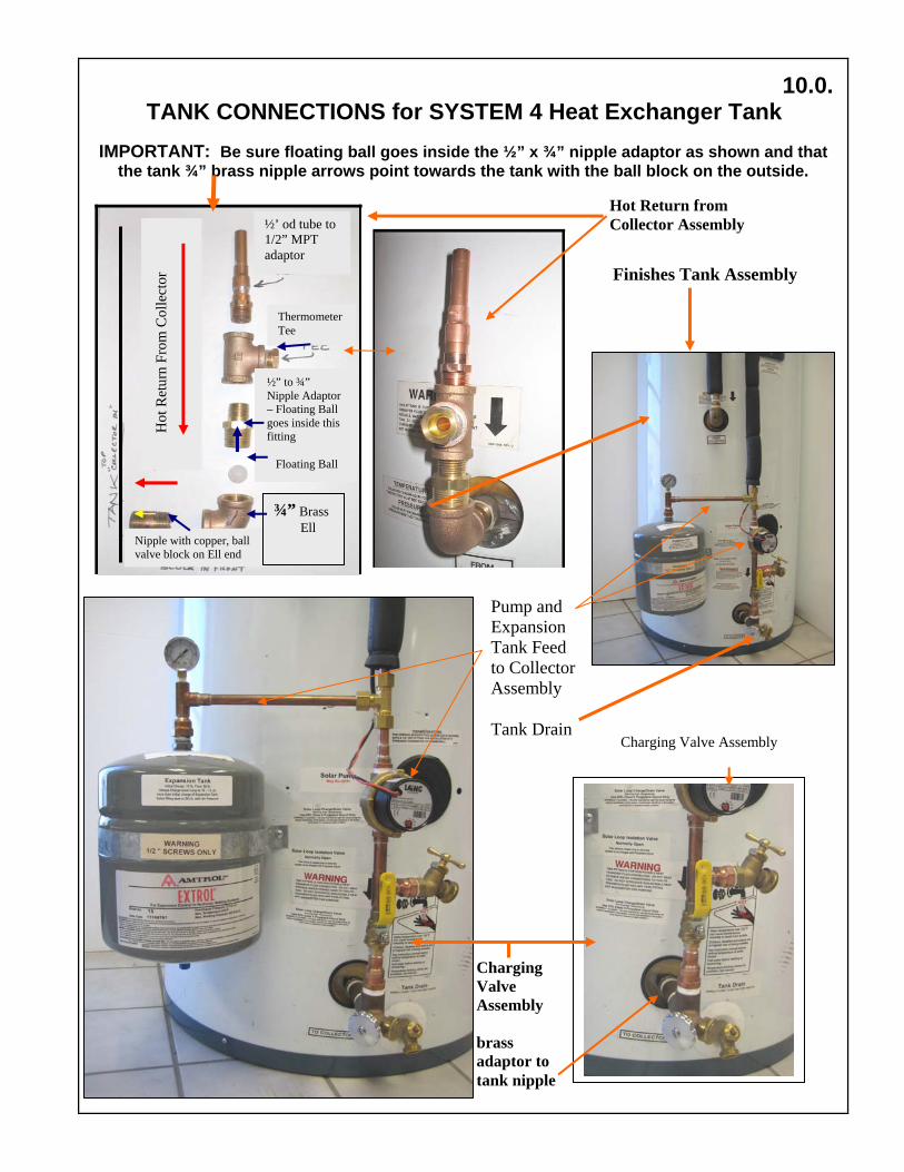
IMPORTANT: Be sure floating ball goes inside the ½” x ¾” nipple adaptor as shown and that the tank ¾” brass nipple arrows point towards the tank with the ball block on the outside.
10.0.TANK CONNECTIONS for SYSTEM 4 Heat Exchanger Tank
Charging Valve Assembly brass adaptor to tank nipple
Charging Valve Assembly
½’ od tube to 1/2” MPT adaptor
Thermometer Tee
½” to ¾” Nipple Adaptor – Floating Ball goes inside this fitting Floating Ball
Hot
Ret
urn
From
Col
lect
or
Nipple with copper, ball valve block on Ell end
¾” Brass Ell
Finishes Tank Assembly
Hot Return from Collector Assembly
Pump and Expansion Tank Feed to Collector Assembly Tank Drain

Installing the Heat Exchanger Connections Refer to Above For Individual Components.
1) The threaded brass fittings are installed using at least 6 tight turns of Teflon Tape or Teflon pipe dope. 2) Heat Exchanger IN (Hot Return): Starting at the bottom with the ¾” brass nipple, connect and tighten the
Hot Return Brass Fittings (with the temperature gauge and check valve) to the TOP Heat Exchanger fitting as shown. Carefully follow the diagram at the top left of the previous page for installing the ball valve. Be sure the check valves brass nipple has the stop facing the outside of the tank so the floating ball does not go inside the nipple.
3) Heat Exchanger OUT (Collector Feed): Starting at the bottom with the ¾” brass nipple, connect and tighten the nipple, attach the ¾” to ½” brass adaptor, ½” street 90, charging valves, 6” nipple, expansion tank and pressure gauge assembly, pump and temperature gauge as shown. Connect the bronze Pump housing with the arrow up.
4) If using non split insulation, put insulation on the feed and return lines prior to connecting lines to talk. 5) Connect the Collector feed line to the tank’s pump feed line using the supplied ½ compression unions. 6) Connect the Collector Hot Return Line to the short Hot Return Tank Fitting. 7) Connect the tank hot and cold lines and Mixing Valves per the diagram below. 8) Charge the system by following one of the 2 procedures in Section 11.0 below. 9) Insulate all water lines including the last 5’ of cold water line as accessible with R-2.6 or greater insulation. 10) The PV pump is simply connected to the switch, which is then connected to the PV panel wires: see 9.0. System 4 “POWER ROD” External Heat Exchanger Many aspects of the installation of the Power Rod are similar to the internal heat exchanger except that there are 2 pumps and all connections are at the top of the tank. It is recommended to use 2 tanks if you have a gas, propane or oil water heater so you will not be heating water already heated by your backup. For gas, propane or oil water heaters, the second tank can be a low cost standard electric water heater with the elements simply being ignored. If a second tank is not possible, you will want to keep the temperature as low as possible and or turned off during summer and times when enough solar energy is available. With a single tank electric water heater, have an electrician disconnect the lower element from the upper element. The cold water coming into the tank will stratify at the bottom of the tank allowing the system to operate at greatest efficiency. The picture below shows the Power Rod as shipped. It will be insulated and secured to the side of your tank as shown in the following pictures.
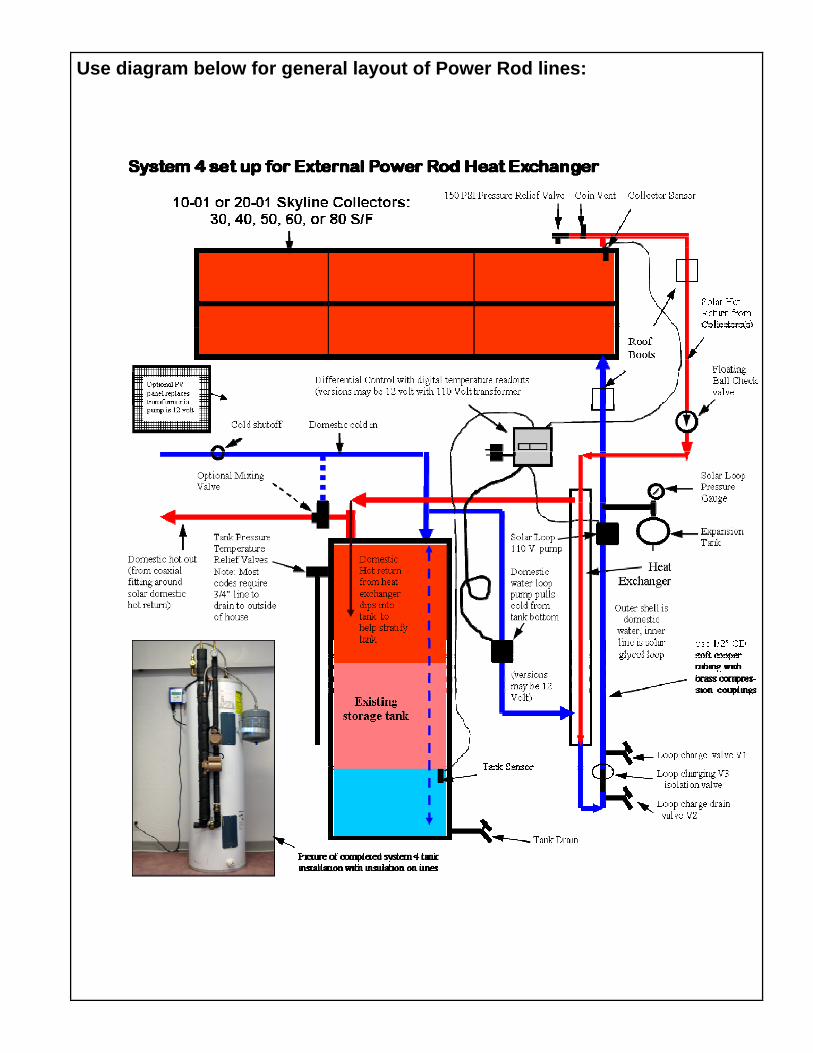
Use diagram below for general layout of Power Rod lines:

The picture below shows a completed Power Rod Heat Exchanger fully installed with the pipes insulated, see detailed drawing below.

The picture below shows the top of the Power Rod including the optional tempering valve installed. Cool return line to collectors from pump Hot return line from collectors Solar Loop Pressure gauge Domestic Hot Return from heat exchanger Cold feed line to tank with connection to domestic side pump to bottom of heat exchanger. Easy connect Flex Line to Expansion tank Before insulating the lines, pressurize the solar loop with water and thoroughly test for leaks.
See following sheet for instructions on pressure testing and charging the Glycol Loop.
NOTE: The optional system 4 mixing valve (which automatically allows cold water to mix into the hot water) is recommended and can be installed by your plumber. There are many was to install the mixing valve as long as the ports ore correct. A check valve is optional. IMPORTANT WARNING: TO AVOID DAMAGE, ALWAYS REMOVE THE INNER PARTS TO THE MIXING VALVE BEFORE SOLDERING.
Mount the sheet titled "Important Warnings and Instructions" onto the front of the tank,
Cut out, peal the backing off and place the supplied labels with their corresponding components.
Optional Tempering Valve showing easy connect cold feed Line Hot feed line to house

Charging the Solar Loop With Propylene Glycol Items Needed: 2 - 5 gallon buckets, 2 or 3 gallons of glycol,
water (use bottom tank drain) charging pump, 3 laundry hoses, air pressure gauge and compressor or tire pump.
3. You can use a low cost hand drill pump like the above or one similar to that shown in the pictures. Be sure to use it with a high speed drill, usually a 110 Volt high speed drill is best to get to 20 - 22 pounds of pressure.
PROFESSIONAL INSTALLER NOTE: A more powerful 110 Volt pump is recommended like Grainger’s Dayton 4CB57 pump. When using a more powerful pump, it is recommended to fill the expansion tank with air to 30 pounds, charge the solar loop with fluid to 40 pounds and then finish off with air to 50 lb.
1. You will need 2 or 3 gallons of Propylene Glycol, Sierra brand or equal, can be picked up at most Auto Parts Stores and Other brands are available at Camping centers where it is used to freeze protect plumbing.
2. To Properly charge the Expansion tank, it is VITAL to not charge more than 10 pounds more fluid pressure in the expansion tank than the original air pressure charge. Charging with fluid to more than 10 pounds over air pressure will flood the Expansion tank with fluid and the bladder may burst, a condition not covered under Warranty.
Check the Pressure in the Expansion tank at the air fill valve on the bottom to be sure it is about 12 pounds (lb), of not, fill to 12 lb. (the system will be charged to 20 – 22 lb) with fluid and topped off at 48 to 50 lb. with air (see 7.)
Bladder with initial charge
pressurized to 12 PSI with no fluid
pressure.
Bladder with 20 PSI of fluid
Results in 20 PSI of air pressure
below bladder = proper charge.
Bladder is flooded because of too
much fluid pressure over
initial charge and may fail.
The diagrams above show the importance of a proper fluid charge in the Expansion Tank. After a proper charge the Expansion Tank is filled through the air fill valve with air to 50 PSI to increase the fluids boiling point in stagnation conditions. A compressor or tire pressure gauge is needed to do this.
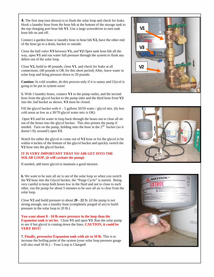
4. The first step (not shown) is to flush the solar loop and check for leaks. Hook a laundry hose from the hose bib at the bottom of the storage tank to the top charging port hose bib V1. Use a large screwdriver to turn tank hose bib on and off. Connect a garden hose or laundry hose to hose bib V2, have the other end of the hose go to a drain, bucket or outside. Close the ball valve V3 between V1, and V2 Open tank hose bib all the way, open V1 and run water full pressure through the system to flush any debris out of the solar loop. Close V2, build to 40 pounds, close V1, and check for leaks at all connections. (40 pounds is OK for this short period) After, leave water in solar loop and bring pressure down to 20 pounds. Caution: In cold weather, do this process only if it is sunny and Glycol is going to be put in system soon!
5. With 3 laundry hoses, connect V1 to the pump outlet, and the second hose from the glycol bucket to the pump inlet and the third hose from V2 into the 2nd bucket as shown. V3 must be closed.
Fill the glycol bucket with 4 – 5 gallons 50/50 water / glycol mix. (In less cold areas as low as a 30/70 glycol water mix is OK)
Open V1 and let water in loop back through the hoses out to clear all air out of the hoses into the glycol bucket. This also primes the pump if needed. Turn on the pump, holding onto the hose in the 2nd bucket (so it doesn’t fly around!) open V2. Watch for either the glycol to come out of V2 hose or for the glycol to be within 4 inches of the bottom of the glycol bucket and quickly switch the V2 hose into the glycol bucket.
IT IS VERY IMPORTANT THAT NO AIR GET INTO THE SOLAR LOOP, (it will cavitate the pump)
If needed, add more glycol to maintain a good mixture.
6. We want to be sure all air is out of the solar loop so when you switch the V2 hose into the Glycol bucket, the “Purge Cycle” is started. Being very careful to keep both hoses low in the fluid and not to close to each other, run the pump for about 5 minutes to be sure all air is clear from the solar loop. Close V2 and build pressure to about 20 - 22 lb. (if the pump is not strong enough, use a laundry hose (completely purged of air) to build pressure in the solar loop to 20 lb.) You want about 8 - 10 lb more pressure in the loop than the Expansion tank is set for. Close V1 and open V3. Run the solar pump to see if hot glycol is coming down the lines, CAUTION, it could be VERY HOT! 7. Finally, pressurize Expansion tank with air to 50 lb. This is to increase the boiling point of the system (your solar loop pressure gauge will also read 50 lb.) – Your Loop is Charged!
V1
V3
V2

We Hope Your installation Went Smoothly!!
PLEASE CALL SolarRoofs.com WITH QUESTIONS OR COMMENTS:
Toll Free USA Install Help Number: (888) 801-9060
Thank You and Now Enjoy the Savings!
11.0. QUESTIONS AND ANSWERS:
HOW DO I GET THE MOST EFFICIENCY FROM MY SOLAR WATER HEATER? An easy method to increase storage efficiency is to have a 220-volt timer installed by an electrician. It will activate the element for 3 hours in the early morning (say from 5AM to 8AM) for showers etc. and on again in the early evening (say from 4PM to 10PM) for evening use if solar gain hasn’t been good that day. This increases the solar efficiency by not allowing the element to come on during hours of solar gain as well as keeping it off during non-use nighttime hours. Ideally, it is most efficient to completely turn off the electricity in sunny weather. WHAT ABOUT FREEZE PROTECTION? The SolarRoofs.com's closed loop Propylene Glycol
Antifreeze heat exchange system's collector as well as feed and return lines will not be damaged by (ambient) hard freeze temperatures as low as -54 degrees F below zero with a 60/40 mixture of propylene glycol/water. The solar storage tank must be kept in an area above 32 degrees F. WHAT ABOUT HIGH TEMPERATURES? The Skyline collector will not be damaged by stagnation in ambient temperatures as high as 120 F. HOW LONG WILL MY PROPYLENE GLYCOL LAST? Quality Propylene Glycol has a life expectancy of up to 10 years but should be checked for acid buildup in the 5 year using standard Litmus paper. Buffers can be added to extend life.
12.0.