Embed Size (px)
Citation preview

Slope Stability Analysis Proceduresy yPresentation for AEG/GI Short Course
UC Riverside, May 12, 2012UC e s de, ay , 0
William Kitch, Cal Poly Pomona
1 © William A Kitch 2012
Overview
Obj ti f t bilit l i Objectives of stability analysis Measures of stability Available computational methods Available computational methods Limit equilibrium methods Stability analysis processStability analysis process Conclusions & questions
2 © William A Kitch 2012

Presentation scope
S il ti k Soil or continuous rock– Does not cover rock behavior governed by jointing (topples, key
wedge, etc)
Translational & rotational modes only– No debris flow or spreading analysis
St ti & d t ti t bilit Static & pseudo static stability– No earthquake deformation analysis
3 © William A Kitch 2012

Objectives of Stability analysis
D t i d f i ti l Determine adequacy of an existing slope Evaluate effectiveness of proposed slope remediation Back calculate average shear strength of a slope know Back calculate average shear strength of a slope know
to be in failure Design an engineered slopeg g
4 © William A Kitch 2012

Measures of stability
F t f f t Factor of safetysF
– where
shear strength availables ilb i h t
– note
equilbrium shear stress
Ms
f
resisting
driving
MsM
– Definition based on shear strength and shear stress is the only consistent definition
5 © William A Kitch 2012

Recommended factors of safety
Cornforth (2005)
Minimal Study Normal StudyLandslide size Borings Acceptable F Borings Acceptable F
Cornforth (2005)
Very Small 1 or none 1.50 1 1.50Small 1 1.50 2 1.35Medium 2 1.40 4 1.25Large 3 1.30 6 1.20Very Large 4 1.20 8 1.15
Uncertainty of analysisCost of failure Small Large
Duncan and Wright (2005)
Cost of failure Small LargeRepair costs y incremental cost of safer design 1.25 1.5Repair costs >> incremental cost of safer design 1.5 2.0 or more6 © William A Kitch 2012

Agency requirements
US Army Corps of Engineers (1970)
Required Factor of safety for given conditionType of slope End of
constructionLong-term steady
state seepageRapid Drawdown
US Army Corps of Engineers (1970)
construction state seepageDams, levees, dikes & other embankments
1.3 1.5 1.0 – 1.2
embankments
Typical Southern California Agency RequirementsStatic Static with pseudo static earthquake load Temporary slopes1.5 1.1 1.25
7 © William A Kitch 2012

Limitations of Factor of safety
D t t i i f ti b t th i bilit Does not contain information about the variability or uncertainty of shear strength or mobilized shear stress
Probability of
bilit
y D
ensi
ty
Probability of failure
Pro
bab
Stresss s Same factor of safety can have different reliability Probabilistic methods are available to estimate reliability
Stresss s
Probabilistic methods are available to estimate reliability of slopes
8 © William A Kitch 2012
Available computational methods
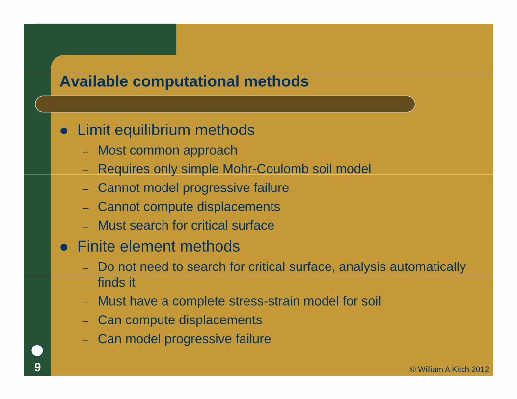
Li it ilib i th d Limit equilibrium methods– Most common approach– Requires only simple Mohr-Coulomb soil modelq y p– Cannot model progressive failure– Cannot compute displacements
Must search for critical surface– Must search for critical surface
Finite element methods– Do not need to search for critical surface, analysis automatically
finds it– Must have a complete stress-strain model for soil– Can compute displacementsp p– Can model progressive failure
9 © William A Kitch 2012

Comparison of limit equilibrium and finite element methods
Limit equilibrium analysis F = 1.75
Finite element analysis F = 1.74
10 © William A Kitch 2012

L ti l f il f ith FE l iLocating complex failure surfaces with FE analysis
1 1.0ussu1
su2
2
1.0us
1 0 6s 1
2
0.6u
u
ss
1
2
0.2u
u
ss
Griffiths & Lane (1999)11 © William A Kitch 2012
Limit Equilibrium Approach
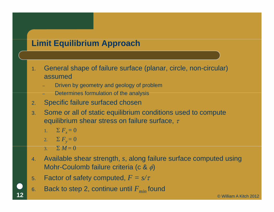
G l h f f il f ( l i l i l )1. General shape of failure surface (planar, circle, non-circular) assumed
– Driven by geometry and geology of problemDetermines formulation of the analysis– Determines formulation of the analysis
2. Specific failure surfaced chosen3. Some or all of static equilibrium conditions used to compute
eq ilibri m shear stress on fail re s rfaceequilibrium shear stress on failure surface, 1. Fx = 02. Fy = 0
M 03. M = 0
4. Available shear strength, s, along failure surface computed using Mohr-Coulomb failure criteria (c & )
5. Factor of safety computed, F = s/6. Back to step 2, continue until Fmin found
12 © William A Kitch 2012
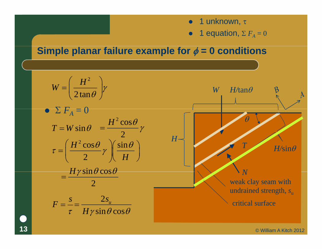
1 unknown, 1 equation, FA = 0
Simple planar failure example for = 0 conditions
2
F 0
2
2 tanHW
H/tanW
FA = 0
sinT W H
2 cos2
H
2 H
H/sin
N
T2 cos sin2
HH
sin cosH N
weak clay seam withundrained strength, su
sin cos2
H
sF 2 us critical surfaceF
sin cos
u
H critical surface
13 © William A Kitch 2012

Simple LE methods
M d l i l b t i t t Model simple but important cases Statically determinate problems Can solve directly for F without assumptions about Can solve directly for F without assumptions about
distribution of stress within failure mass Most common and useful methods
– Planar or single wedge– Infinite slope
Swedish slip circle– Swedish slip circle
14 © William A Kitch 2012

2 unknowns, F & 2 equations
– FA = 0Infinite slope analysis
FA = 0
FA 0– FB = 0
FA 0
FB = 0D
sinT W sinWl cos sinD
cosW
From Mohr-Coulomb
t
D
cosN W cosWl 2cosD
2DW tan 's c 2cos tan 'c D
2cos tan 'cos sin
s c DFD
EL
ER
For c = 0l
T
2cos tan 'cos sin
DFD
tan 'tan
For = 0, s = su
costl
W tD
NT
cos sinusF
D
15 © William A Kitch 2012

1 unknown, F 1 equation, MO = 0
Swedish slip circle for = 0 conditions
M 0O MO = 0
W
a r lr Wa
Wal1
su1 su
Shear strength
W
l
rl
s sl2
su2
us s
sF
us rlWa
l2
resisting
driving
MF
M r s l ui ir s l
FWa
16 © William A Kitch 2012
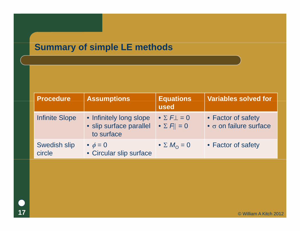
Summary of simple LE methods
Procedure Assumptions Equations Variables solved forocedu e ssu pt o s quat o sused
a ab es so ed o
Infinite Slope • Infinitely long slope• slip surface parallel
• F = 0• F = 0
• Factor of safety• on failure surface
to surfaceSwedish slip circle
• = 0 • Circular slip surface
• MO = 0 • Factor of safety
17 © William A Kitch 2012

Methods of slices
Wh 0O When 0
Must determine ' ' tan 's c r
c1, 1
Cannot use simply MO = 0c2, 2
zi Vi
i
zi+1Wi
i
Ei
Vi
Ei+1
Ti
Vi+1
i+1
li
Ni
18 © William A Kitch 2012

Equation/unknown count
x Unknowns
F, factor of safety n values of N zi+1
Wi
zi
E
Vi
x
z
n values of Ni
n1 values of Ei
n1 values of Vi
n 1 values of z
i+1Ei
Vi+1
Ei+1
n1 values of zi
Total: 4n2 unknowns Equilibrium equations
1 M
lNi
Ti
1, MO
n, Mi
n, Fx Must make assumptions to
solve problem
li
n, Fz
Total: 3n + 1 equations
solve problem Assumptions made affect
accuracy of solution19 © William A Kitch 2012

1 unknown, F 1 equation, MO = 0
Ordinary method of slices
Assumptions– Circular surface
Ignore all side forces
Wi Ignore side forces
Ignore side forces
– Ignore all side forces Unknown
– FE ti d
forcesHi
Equations used– MO = 0
SolutionNi
Ti
li
Can directly solve for F Simple to implement Generally conservative
' cos tan 'sin
c l W ulF
W
l Generally conservative
Accuracy poor when pore pressure high
cos pore pressure on base of slice
W Hlu
20 © William A Kitch 2012

1+n unknowns, F, Ni
1 equation, MO = 0
Simplified bishop method
x
MO 0 n, Fz
Assumptions– Circular surface
Side forces are horizontalzi+1
Wi
zi
Ei
x
z
– Side forces are horizontal Unknown
– 1, FN
Ei+1
– n, Ni
Equations used– MO = 0
li
Ni
Ti
– n, Fz
Solution Requires iterative solution More accurate the OMS
E il i l d i h
i
' cos cos tan 'c l W ul Easily implemented with
spreadsheet
cos sin tan ' /
sinF
FW
21 © William A Kitch 2012

Inclusion of external or internal loads
O
rk Wi zi+1
Wi
zi
Ei k Wi
Ri
Ei+1
Ri
Know forces included in
i
ili
Ni
Ti
Know forces included in existing equilibrium equations
Does not increase number of unknowns
Allows for inclusion of– Pseudo static earthquake loads– Forces from pile stabilization
i
unknowns Solution method the same
– External equipment or structural loads
22 © William A Kitch 2012

Uses of non-circular surfaces
Surficial Slide
Weak seam
Weak layer23 © William A Kitch 2012
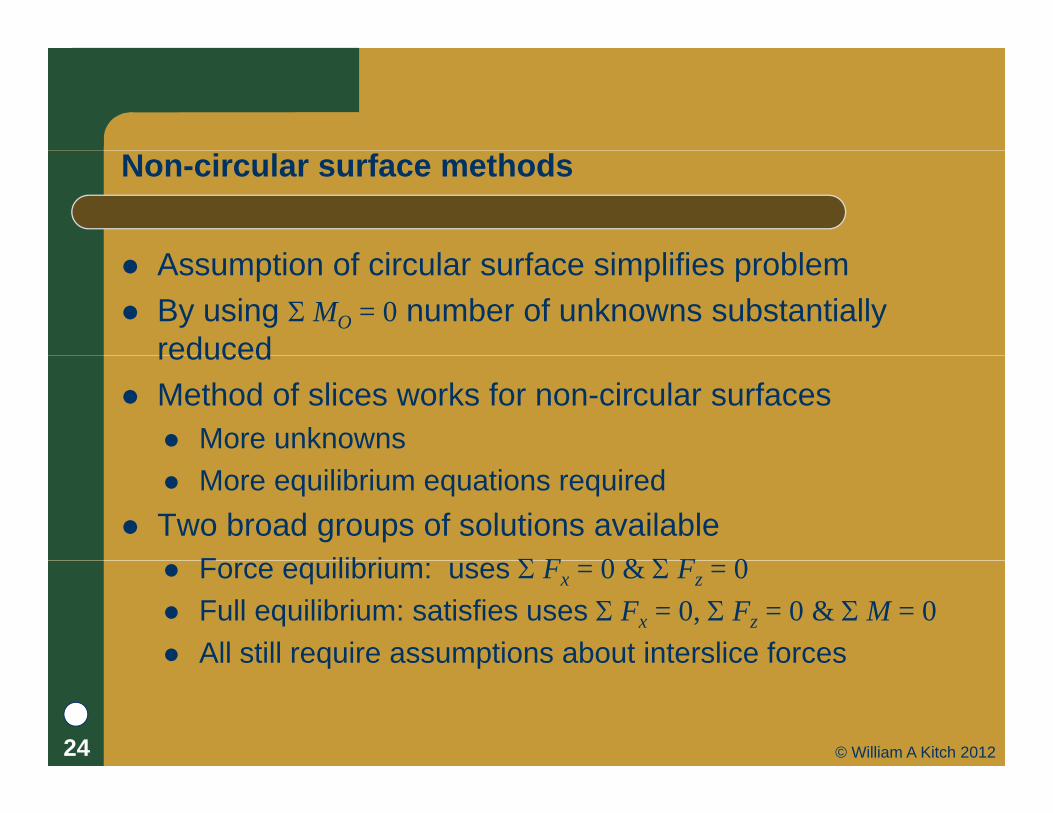
Non-circular surface methods
A ti f i l f i lifi bl Assumption of circular surface simplifies problem By using MO = 0 number of unknowns substantially
reducedreduced Method of slices works for non-circular surfaces
More unknowns More equilibrium equations required
Two broad groups of solutions availableF ilib i F 0 & F 0 Force equilibrium: uses Fx = 0 & Fz = 0
Full equilibrium: satisfies uses Fx = 0, Fz = 0 & M = 0 All still require assumptions about interslice forcesq p
24 © William A Kitch 2012

Force equilibrium methods
A di ti i t li f Assume direction interslice forces– Combined with Fx = 0 & Fz = 0 allows for solution for F
Method Interslice force assumption
Simplified Janbu (Janbu et al.1956) Horizontalp ( )
Lowe and Karafiath (1959) Average of slope of top and bottom of slice
Corps of Engineers’ modified Swedish method (US Army Corps of Engineers, 1970)
Parallel to average slope angle
25 © William A Kitch 2012

Force equilibrium solutions sensitive to direction of interslice force
Figure 6.15 Influence of interslice force inclination on the computed factor of safety forFigure 6.15 Influence of interslice force inclination on the computed factor of safety for force equilibrium with parallel interslice forces. (Duncan & Wright, 2005)
26 © William A Kitch 2012

Full equilibrium methods
Add t ilib i t & f ilib i Add moment equilibrium to x & y force equilibrium Still requires assumptions Two most common methods
– Spencer (1967) Assumes all interslice forces are parallel Solves for F and
– Morgenstern and Price (1965) Assumes V = f (x) E
– f (x) is an assumed function– is a scaling constant
is a scaling constant Solves for F and
– Morgenstern & Price more general– Spencer easier to implement
f(x)
p p When using any full equilibrium method F is insensitive to
assumptions about interslice forces27 © William A Kitch 2012

Comparison of full equilibrium methods
P d A ti E ti V i bl l d fProcedure Assumptions Equations used
Variables solved for
Spencers • Interslice forces parallel
• Fx = 0• F = 0
• Factor of safety• Interslice angle parallel • Fy = 0
• M = 0• Interslice angle • Interslice force• Location of
interslice force• on failure surface
Morgenstern& Price
• Interslice forces related by V = f (x) EF f f ( )
• Fx = 0• Fy = 0 M 0
• Factor of safety• Scaling factor
I t li f• Form of f (x) • M = 0 • Interslice force• Location of
interslice force• on failure surface
28 © William A Kitch 2012

Data available from full equilibrium method
29 © William A Kitch 2012

Summary of applicability of LE methodsy pp yProcedure Application
Infinite Slope Homogeneous cohesionless slopes and slopes where the stratigraphy restricts the slip surface to shallow depths and parallelstratigraphy restricts the slip surface to shallow depths and parallel to the slope face. Very accurate where applicable.
Swedish Circle = 0
Undrained analyses in saturated clays, = 0. Relatively thick zones of weaker materials where circular surface is appropriate.
Ordinary Method of Slices
Nonhomogeneous slopes and c– soils where circular surface is appropriate. Convenient for hand calculations. Inaccurate for effective stress analyses with high pore pressures.
Simplified Bishop Nonhomogeneous slopes and c soils where circular surface isSimplified Bishop procedure
Nonhomogeneous slopes and c– soils where circular surface is appropriate. Better than OMS. Calculations feasible by spreadsheet
Force Equilibrium procedures
Applicable to virtually all slopes. Less accurate than complete equilibrium procedures and results sensitive to p q passumed interslice force angles.
Spencer Applicable to virtually all slopes. The simplest full equilibrium procedure for computing the factor of safety.
Morgenstern and Price
Applicable to virtually all slopes. Rigorous, well-established complete equilibrium procedure.
From Duncan & Wright (2005)30 © William A Kitch 2012

Critical details of LE analysis
S hi f iti l f Searching for critical surface– Check for multiple minima– Special attention required when using non-circular surfacesp q g
Select appropriate shear strength– Progressive failure
P i ti h f– Pre-existing shear surfaces
Check for invalid solutions– Tensile forces near crest – Steep exit slopes– Non-convergence of solutions
31 © William A Kitch 2012

Critical surface search: regional minimum
32 © William A Kitch 2012

Critical surface search: local minimum
33 © William A Kitch 2012
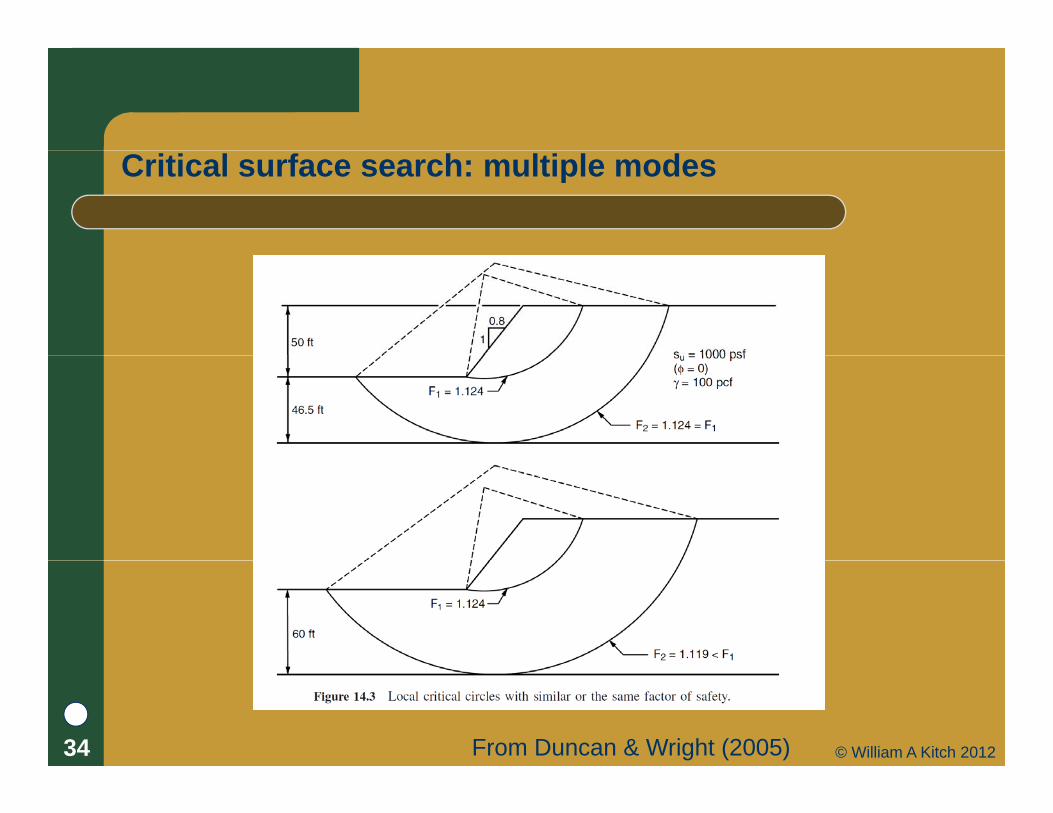
Critical surface search: multiple modes
From Duncan & Wright (2005)34 © William A Kitch 2012

Progressive failure
From Duncan & Wright (2005)35 © William A Kitch 2012

Validity of solution: Tension crack at crest
Al h k li f th t Always check line of thrust
36 © William A Kitch 2012

Validity of solution: Tension crack at crest
I t t i k t t if d d Insert tension crack at crest if needed
37 © William A Kitch 2012

Steep exit angle
C Can cause – Non-convergence of solution– Very high stresses y g– Negative (tensile stresss)
SolutionU Si lifi d Bi h– Use Simplified-Bishop
– For exit slope to be more shallow
From Duncan & Wright (2005)38 © William A Kitch 2012

Preparing for stability analysis
D t i i d f l i Determine required scope of analysis Assess risk of project and select appropriate F Build subsurface model Build subsurface model Determine drainage conditions which apply
– End-of-construction undrained condition– Long-term drained condition (both?)
Select appropriate soil strength propertiesId tif t f il f t d l t Identify expect failure surface geometry and select analysis procedure– Circular non-cirucular
Select appropriate analysis procedure39 © William A Kitch 2012

Performing stability analysis
I ti t t ti l f il d i i l d l Investigate potential failure modes using simple models– Identify areas where F is low
Adjust subsurface model and analysis method as needed– Soil properties, geometry, computational method
Thoroughly investigate all potential failure modes with rigorous search for critical surface
– Search all area with local minimum– Consider risk of each significant failure mode
Thoroughly examine computations for critical modes – Check line of thrust
Sanity check results– Similar project, hand computation, other methodp j , p ,
40 © William A Kitch 2012

Software (a very short list)
St d l t bilit k Standalone stability packages– STABL/STED– Oasysy– UTEXAS4– LimitState
Integrated packages Integrated packages– RocScience– GeoStudio– gINT– SoilVision
41 © William A Kitch 2012

Recommended texts
Ab L W (2002) Sl t bilit d t bili ti Abramson, L. W. (2002). Slope stability and stabilization methods. Wiley, New York.
Cornforth D H (2005) Landslides in Practice - Cornforth, D. H. (2005). Landslides in Practice Investigation, Analysis, and Remedial/Preventative Options in Soils. John Wiley & Sons.
Duncan, J. M., and Wright, S. G. (2005). Soil Strength and Slope Stability. John Wiley & Sons, Hoboken, N.J.
42 © William A Kitch 2012

References
Abramson L W (2002) Slope stability and stabilization methods Wiley New York Abramson, L. W. (2002). Slope stability and stabilization methods. Wiley, New York. Cornforth, D. H. (2005). Landslides in Practice - Investigation, Analysis, and
Remedial/Preventative Options in Soils. John Wiley & Sons. Duncan, J. M., and Wright, S. G. (2005). Soil Strength and Slope Stability. John Wiley & Sons,
Hoboken N JHoboken, N.J. Griffiths, D. V., and Lane, P. A. (1999). “Slope stability analysis by finite elements.”
Geotechnique, 49(3), 387–403. Janbu, N., Bjerrum, L., and Kjærnsli, B. (1956). Veiledning ved Løsning av
Fundamenteringsoppgaver (Soil Mechanics Applied to Some Engineering Problems), PublicationFundamenteringsoppgaver (Soil Mechanics Applied to Some Engineering Problems), Publication 16, Norwegian Geotechnical Institute, Oslo.
Lowe, J., and Karafiath, L. (1959). Stability of earth dams upon drawdown, Proceedings of the First PanAmerican Conference on Soil Mechanics and Foundation Engineering, Mexico City, Vol. 2, pp. 537–552.
Morgenstern, N. R., and Price, V. E. (1965). “The analysis of the stability of general slip surfaces”, Geotechnique, 15(1), 79–93.
Spencer, E. (1967). “A method of analysis of the stability of embankments assuming parallel inter-slice forces”, Geotechnique, 17(1), 11–26.
U.S. Army Corps of Engineers (1970). Engineering and Design:Stability of Earth and Rock-Fill Dams, Engineer Manual EM 1110-2-1902, Washington, DC, April.
43 © William A Kitch 2012