Embed Size (px)
DESCRIPTION
Slope Stab Risk Mgm Nt
Citation preview
INSTITUTE OF QUARRYING
& ASPASA
36th ANNUAL CONFERENCE & EXHIBITIONBirchwood Conference Centre,
Gauteng3-5 MARCH 2005
SLOPE STABILITY RISKMANAGEMENT AT ANGLOPLATINUM’S SANDSLOOT
OPEN PITBy
Alan Bye, Geotechnical Engineer, Anglo PlatinumMegan Little, Rock Engineer, PPRust, Anglo
PlatinumDesmond Mossop, Manager Rock Engineering,
PPRust, Anglo Platinum

INSTITUTE OF QUARRYING SOUTHERN AFRICA Incorporating ASPASA
36TH CONFERENCE & EXHIBITION – 3-5 MARCH 2005
‘SLOPE STABILITY RISK MANAGEMENT AT ANGLOPLATINUM’S SANDSLOOT OPEN PIT’ Author/Speaker: Alan Bye - Geotechnical Engineer, Anglo Platinum – Miningand Geological Services
Alan Bye graduated from the University of Natal, Durban in 1997 as an Anglo Platinumbursar and subsequently, during part time study, obtained a PhD in engineering geology(2003). He has published and presented over 25 papers in a series of internationaljournals and conferences on applied engineering geology and open pit mining. Alan hasreceived numerous awards for his geotechnical research and is a regular lecturer at theWITS university mining engineering department.
Alan has had experience in exploration and production geology, open pit geotechnics, drill& blast engineering and water resource management. Alan gained the majority of hisexperience at Potgietersrust Platinum where he was ultimately employed as theOperations Manager. He has also served as an open pit geotechnical consultant for SRKConsulting Engineers.
Currently he is employed as a consulting geotechnical engineer in Anglo Platinum’scorporate office where he is responsible for drill & blast optimisation, geotechnical projectsand predominantly mine to mill integration.
‘Slope Stability Risk Management at Anglo Platinum’s Sandsloot Open Pit’Author/Speaker: Alan Bye - Geotechnical Engineer, Anglo Platinum – Mining & Geological ServicesCo-Authors: Megan Little – Rock Engineer, Desmond Mossop – Manager, Rock Engineering –PPRust, Anglo Platinum
INSTITUTE OF QUARRYING SOUTHERN AFRICA Incorporating ASPASA
36TH CONFERENCE & EXHIBITION – 3-5 MARCH 2005
1 INTRODUCTION
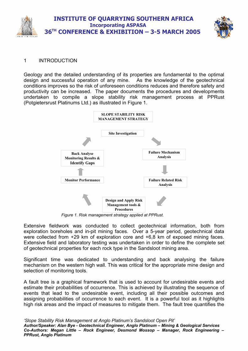
Geology and the detailed understanding of its properties are fundamental to the optimaldesign and successful operation of any mine. As the knowledge of the geotechnicalconditions improves so the risk of unforeseen conditions reduces and therefore safety andproductivity can be increased. The paper documents the procedures and developmentsundertaken to compile a slope stability risk management process at PPRust(Potgietersrust Platinums Ltd.) as illustrated in Figure 1.
SLOPE STABILITY RISK MANAGEMENT STRATEGY
Site Investigation
Failure Mechanism Analysis
Failure Related Risk Analysis
Monitor Performance
Design and Apply Risk Management tools &
Procedures
Back AnalyseMonitoring Results &
Identify Gaps
Figure 1. Risk management strategy applied at PPRust.
Extensive fieldwork was conducted to collect geotechnical information, both fromexploration boreholes and in-pit mining faces. Over a 5-year period, geotechnical datawere collected from +29 km of exploration core and +6,8 km of exposed mining faces.Extensive field and laboratory testing was undertaken in order to define the complete setof geotechnical properties for each rock type in the Sandsloot mining area.
Significant time was dedicated to understanding and back analysing the failuremechanism on the western high wall. This was critical for the appropriate mine design andselection of monitoring tools.
A fault tree is a graphical framework that is used to account for undesirable events andestimate their probabilities of occurrence. This is achieved by illustrating the sequence ofevents that lead to the undesirable event, including all their possible outcomes andassigning probabilities of occurrence to each event. It is a powerful tool as it highlightshigh risk areas and the impact of measures to mitigate them. The fault tree quantifies the
‘Slope Stability Risk Management at Anglo Platinum’s Sandsloot Open Pit’Author/Speaker: Alan Bye - Geotechnical Engineer, Anglo Platinum – Mining & Geological ServicesCo-Authors: Megan Little – Rock Engineer, Desmond Mossop – Manager, Rock Engineering –PPRust, Anglo Platinum
INSTITUTE OF QUARRYING SOUTHERN AFRICA Incorporating ASPASA
36TH CONFERENCE & EXHIBITION – 3-5 MARCH 2005
risk and enables management to make informed decisions on the level of risk they arewilling to operate at.
Wall control blasting at PPL is stringently applied using pre-splitting, narrow trim blasts,small diameter holes and electronic detonators. The strength of the joints occurring in thewestern high wall are inadequate to resist even small blast hole pressures and it wastherefore important to assess the extent of the joint damage behind the pre-split walls asthis would strongly influence the frequency and size of slope failures.
Conventional survey methods, whereby prisms on the crest or face are measured by theSurvey department, only provided limited location and time coverage and did notadequately manage the risk presented by these failures. This was due to the small scaleof the failures and limited monitoring coverage. The GroundProbe slope stability radar(SSR) was trialled as a possible risk management tool. The SSR has been developed toremotely scan a rock slope and continuously monitor the spatial deformation of the face.Using differential radar interferometry, the system can detect deformation movements of arough wall with sub-millimetre accuracy, and with high spatial and temporal resolution.The radar currently has a range of 850m and a typical scan will take 8-12 minutes tocomplete. The aim of the trial period was to determine whether the radar was able tomeasure and alert operations personnel of brittle rock, slope failures, occurring in thenorite hanging wall.
2 MINING OVERVIEW
In 1924, Dr. Hans Merensky located platinum-bearing reef in both the Rustenburg and thePotgietersrus areas. This subsequently resulted in a “platinum rush” and a scramble formineral prospecting options in both regions. In 1925, over fifty companies had beenfloated to exploit the deposits of the Bushveld Complex. One of the more prominent wasPotgietersrust Platinums Limited (PPL).
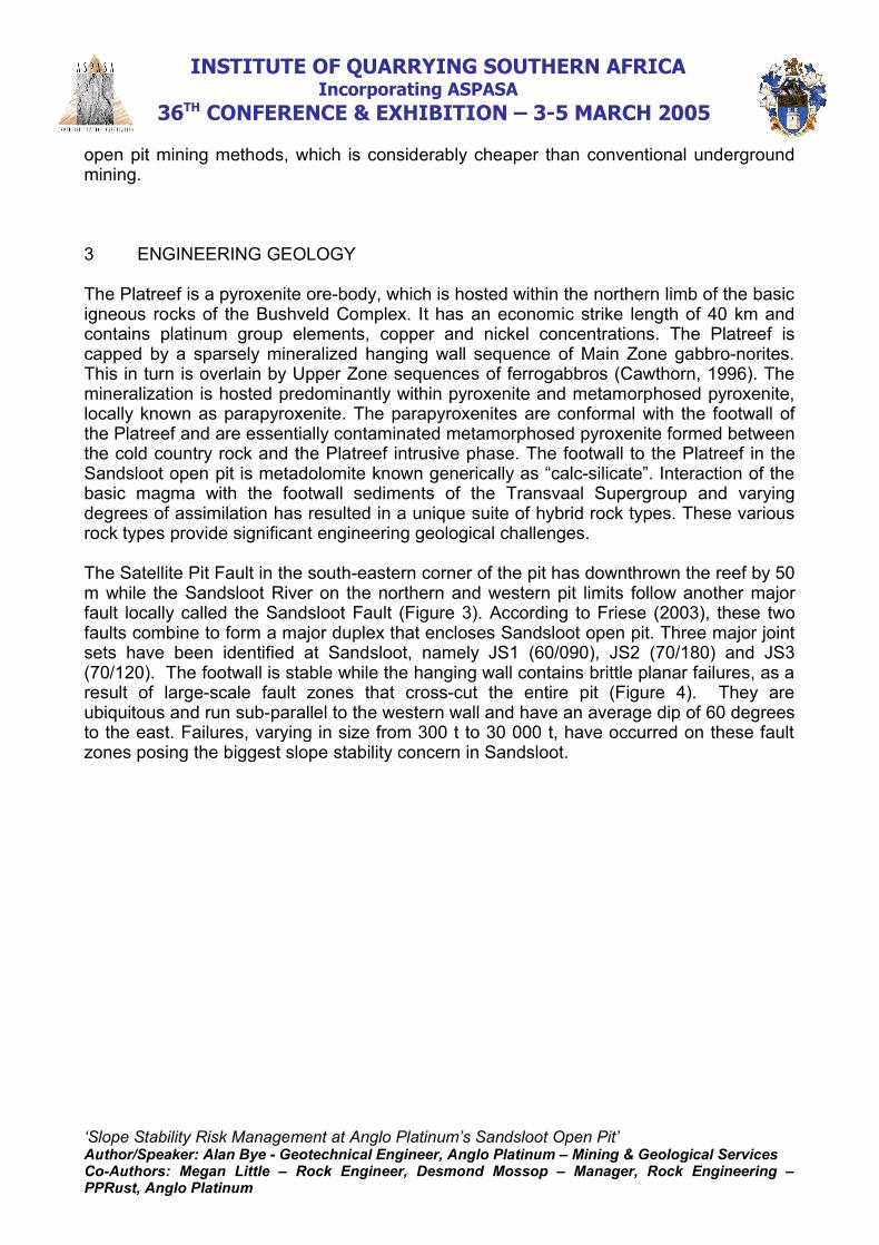
Sandsloot open pit was developed in 1992 to extract the platinum-bearing, Platreef orebody, which is hosted within the Northern Limb of the Bushveld Complex, some 250 kmnorth-east of Johannesburg (Figure 2). The current open pit is roughly 1 500 m long, 800m wide and strikes north. It is the first of six potential open pits to be mined by PPRust, asubsidiary of Anglo Platinum.
Sandsloot is currently the world’s largest open pit exploiting platinum group metals (PGMs).In a single month the mine processes 400,000 tonnes of ore and excavates 50 milliontonnes of ex-pit material annually. 25 million tonnes are mined from each of the Sandslootand Zwartfontein South pits respectively. The Sandsloot open pit is in the process of afourth cutback, which has a final depth of 200 m below surface while later cutbacks willextend this to a maximum of 320 m. The benches are 15 m in height and mining blocksare usually 100 m x 50 m. The ramps are 35m wide and have a gradient of 10%. Thecurrent pit has an economic depth of 320m, after which underground mining maycommence.
The Platreef ore body at Sandsloot is tabular in geometry, dips at 45 and isapproximately 50 m in width. These properties allow the ore body to be excavated by
‘Slope Stability Risk Management at Anglo Platinum’s Sandsloot Open Pit’Author/Speaker: Alan Bye - Geotechnical Engineer, Anglo Platinum – Mining & Geological ServicesCo-Authors: Megan Little – Rock Engineer, Desmond Mossop – Manager, Rock Engineering –PPRust, Anglo Platinum
INSTITUTE OF QUARRYING SOUTHERN AFRICA Incorporating ASPASA
36TH CONFERENCE & EXHIBITION – 3-5 MARCH 2005
open pit mining methods, which is considerably cheaper than conventional undergroundmining.
3 ENGINEERING GEOLOGY
The Platreef is a pyroxenite ore-body, which is hosted within the northern limb of the basicigneous rocks of the Bushveld Complex. It has an economic strike length of 40 km andcontains platinum group elements, copper and nickel concentrations. The Platreef iscapped by a sparsely mineralized hanging wall sequence of Main Zone gabbro-norites.This in turn is overlain by Upper Zone sequences of ferrogabbros (Cawthorn, 1996). Themineralization is hosted predominantly within pyroxenite and metamorphosed pyroxenite,locally known as parapyroxenite. The parapyroxenites are conformal with the footwall ofthe Platreef and are essentially contaminated metamorphosed pyroxenite formed betweenthe cold country rock and the Platreef intrusive phase. The footwall to the Platreef in theSandsloot open pit is metadolomite known generically as “calc-silicate”. Interaction of thebasic magma with the footwall sediments of the Transvaal Supergroup and varyingdegrees of assimilation has resulted in a unique suite of hybrid rock types. These variousrock types provide significant engineering geological challenges.
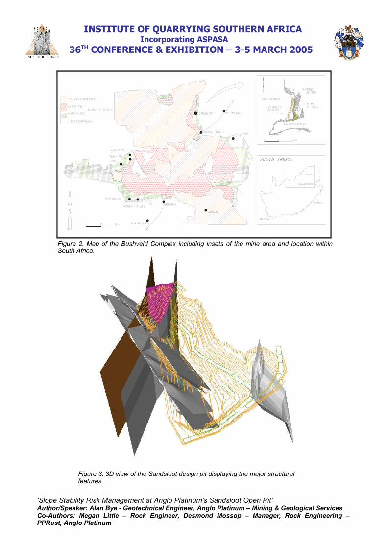
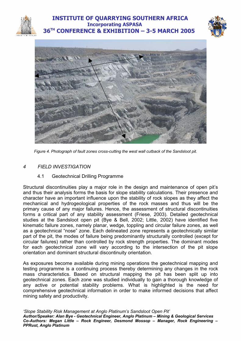
The Satellite Pit Fault in the south-eastern corner of the pit has downthrown the reef by 50m while the Sandsloot River on the northern and western pit limits follow another majorfault locally called the Sandsloot Fault (Figure 3). According to Friese (2003), these twofaults combine to form a major duplex that encloses Sandsloot open pit. Three major jointsets have been identified at Sandsloot, namely JS1 (60/090), JS2 (70/180) and JS3(70/120). The footwall is stable while the hanging wall contains brittle planar failures, as aresult of large-scale fault zones that cross-cut the entire pit (Figure 4). They areubiquitous and run sub-parallel to the western wall and have an average dip of 60 degreesto the east. Failures, varying in size from 300 t to 30 000 t, have occurred on these faultzones posing the biggest slope stability concern in Sandsloot.
‘Slope Stability Risk Management at Anglo Platinum’s Sandsloot Open Pit’Author/Speaker: Alan Bye - Geotechnical Engineer, Anglo Platinum – Mining & Geological ServicesCo-Authors: Megan Little – Rock Engineer, Desmond Mossop – Manager, Rock Engineering –PPRust, Anglo Platinum
INSTITUTE OF QUARRYING SOUTHERN AFRICA Incorporating ASPASA
36TH CONFERENCE & EXHIBITION – 3-5 MARCH 2005
Figure 2. Map of the Bushveld Complex including insets of the mine area and location withinSouth Africa.
Figure 3. 3D view of the Sandsloot design pit displaying the major structuralfeatures.
‘Slope Stability Risk Management at Anglo Platinum’s Sandsloot Open Pit’Author/Speaker: Alan Bye - Geotechnical Engineer, Anglo Platinum – Mining & Geological ServicesCo-Authors: Megan Little – Rock Engineer, Desmond Mossop – Manager, Rock Engineering –PPRust, Anglo Platinum
INSTITUTE OF QUARRYING SOUTHERN AFRICA Incorporating ASPASA
36TH CONFERENCE & EXHIBITION – 3-5 MARCH 2005
Figure 4. Photograph of fault zones cross-cutting the west wall cutback of the Sandsloot pit.
4 FIELD INVESTIGATION
4.1 Geotechnical Drilling Programme
Structural discontinuities play a major role in the design and maintenance of open pit’sand thus their analysis forms the basis for slope stability calculations. Their presence andcharacter have an important influence upon the stability of rock slopes as they affect themechanical and hydrogeological properties of the rock masses and thus will be theprimary cause of any major failures. Hence, the assessment of structural discontinuitiesforms a critical part of any stability assessment (Friese, 2003). Detailed geotechnicalstudies at the Sandsloot open pit (Bye & Bell, 2002; Little, 2002) have identified fivekinematic failure zones, namely planar, wedge, toppling and circular failure zones, as wellas a geotechnical “nose” zone. Each delineated zone represents a geotechnically similarpart of the pit, the modes of failure being predominantly structurally controlled (except forcircular failures) rather than controlled by rock strength properties. The dominant modesfor each geotechnical zone will vary according to the intersection of the pit slopeorientation and dominant structural discontinuity orientation.
As exposures become available during mining operations the geotechnical mapping andtesting programme is a continuing process thereby determining any changes in the rockmass characteristics. Based on structural mapping the pit has been split up intogeotechnical zones. Each zone was studied individually to gain a thorough knowledge ofany active or potential stability problems. What is highlighted is the need forcomprehensive geotechnical information in order to make informed decisions that affectmining safety and productivity.
‘Slope Stability Risk Management at Anglo Platinum’s Sandsloot Open Pit’Author/Speaker: Alan Bye - Geotechnical Engineer, Anglo Platinum – Mining & Geological ServicesCo-Authors: Megan Little – Rock Engineer, Desmond Mossop – Manager, Rock Engineering –PPRust, Anglo Platinum
INSTITUTE OF QUARRYING SOUTHERN AFRICA Incorporating ASPASA
36TH CONFERENCE & EXHIBITION – 3-5 MARCH 2005
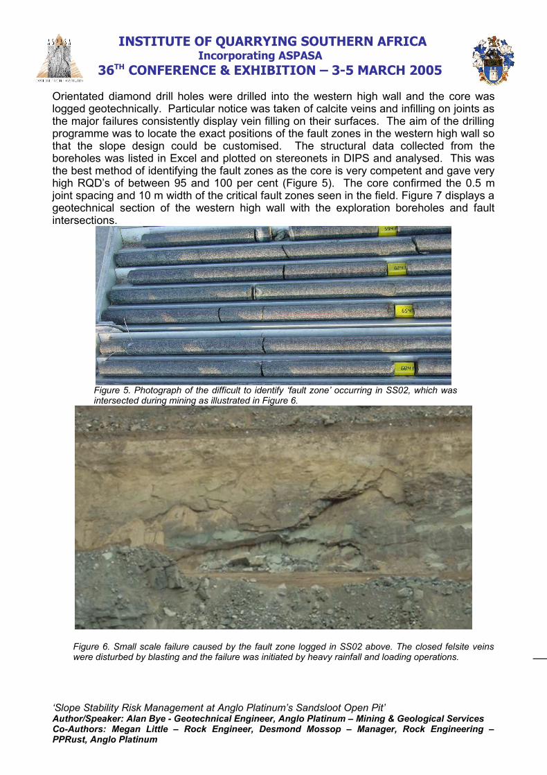
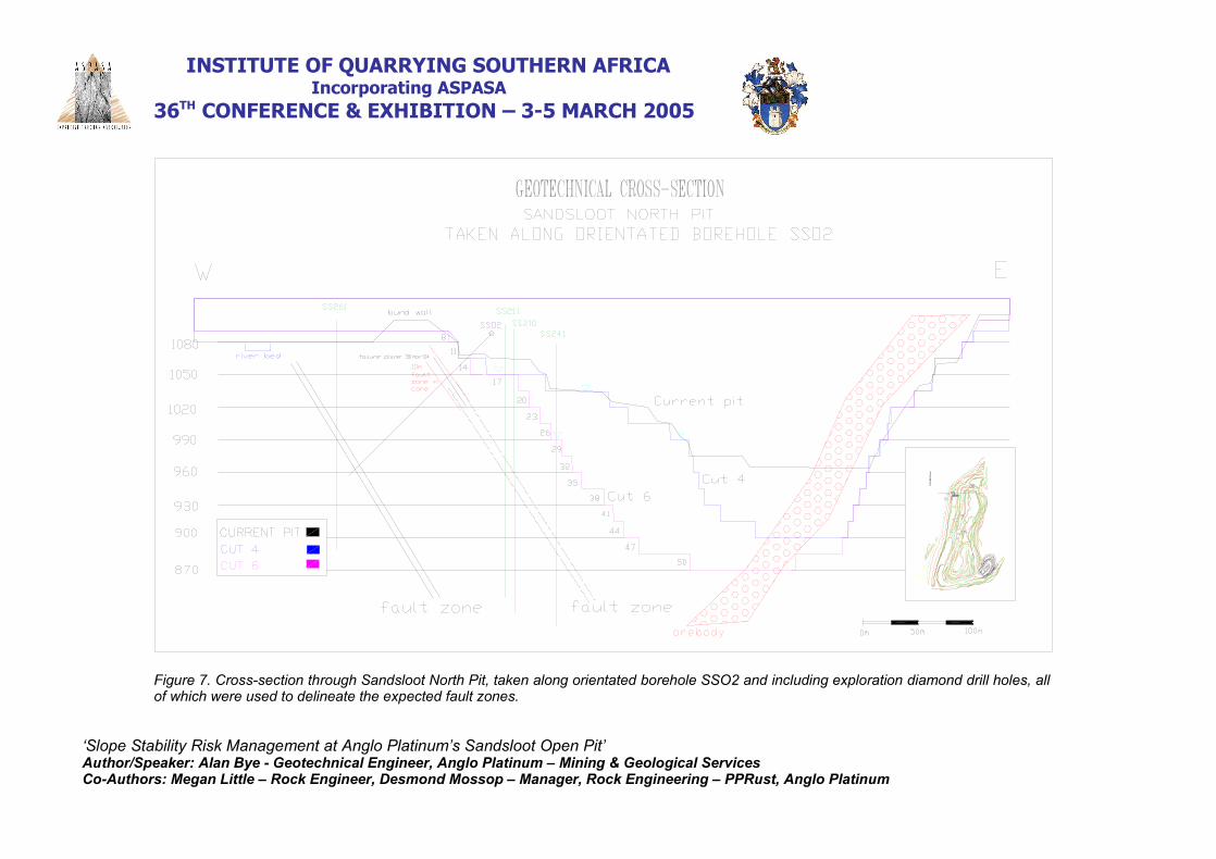
Orientated diamond drill holes were drilled into the western high wall and the core waslogged geotechnically. Particular notice was taken of calcite veins and infilling on joints asthe major failures consistently display vein filling on their surfaces. The aim of the drillingprogramme was to locate the exact positions of the fault zones in the western high wall sothat the slope design could be customised. The structural data collected from theboreholes was listed in Excel and plotted on stereonets in DIPS and analysed. This wasthe best method of identifying the fault zones as the core is very competent and gave veryhigh RQD’s of between 95 and 100 per cent (Figure 5). The core confirmed the 0.5 mjoint spacing and 10 m width of the critical fault zones seen in the field. Figure 7 displays ageotechnical section of the western high wall with the exploration boreholes and faultintersections.
Figure 5. Photograph of the difficult to identify ‘fault zone’ occurring in SS02, which wasintersected during mining as illustrated in Figure 6.
Figure 6. Small scale failure caused by the fault zone logged in SS02 above. The closed felsite veinswere disturbed by blasting and the failure was initiated by heavy rainfall and loading operations.
‘Slope Stability Risk Management at Anglo Platinum’s Sandsloot Open Pit’Author/Speaker: Alan Bye - Geotechnical Engineer, Anglo Platinum – Mining & Geological ServicesCo-Authors: Megan Little – Rock Engineer, Desmond Mossop – Manager, Rock Engineering –PPRust, Anglo Platinum

INSTITUTE OF QUARRYING SOUTHERN AFRICA Incorporating ASPASA
36TH CONFERENCE & EXHIBITION – 3-5 MARCH 2005
Figure 7. Cross-section through Sandsloot North Pit, taken along orientated borehole SSO2 and including exploration diamond drill holes, allof which were used to delineate the expected fault zones.
‘Slope Stability Risk Management at Anglo Platinum’s Sandsloot Open Pit’Author/Speaker: Alan Bye - Geotechnical Engineer, Anglo Platinum – Mining & Geological ServicesCo-Authors: Megan Little – Rock Engineer, Desmond Mossop – Manager, Rock Engineering – PPRust, Anglo Platinum

INSTITUTE OF QUARRYING SOUTHERN AFRICA Incorporating ASPASA
36TH CONFERENCE & EXHIBITION – 3-5 MARCH 2005
4.2 Field Mapping
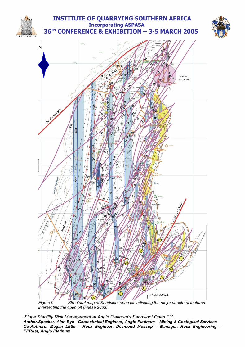
Detailed line mapping was performed throughout Sandsloot pit on accessible faces andcombined with the existing geotechnical mapping database. Interpretation of geophysicaland remote-sensing data sets was undertaken on a regional scale and diamond drillexploration core was assessed (Friese, 2003). The aim of this work was to delineate thefault zones and the major structures at Sandsloot and create a Structural InterpretationMap of the pit (Figure 9).
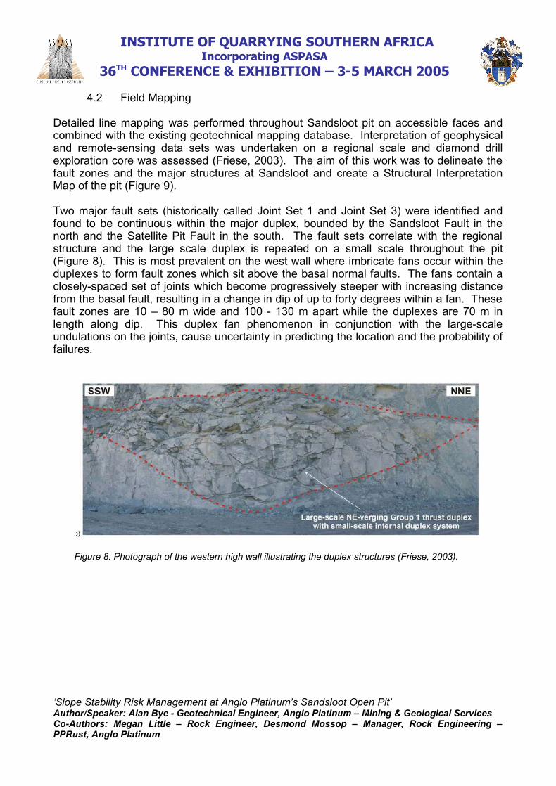
Two major fault sets (historically called Joint Set 1 and Joint Set 3) were identified andfound to be continuous within the major duplex, bounded by the Sandsloot Fault in thenorth and the Satellite Pit Fault in the south. The fault sets correlate with the regionalstructure and the large scale duplex is repeated on a small scale throughout the pit(Figure 8). This is most prevalent on the west wall where imbricate fans occur within theduplexes to form fault zones which sit above the basal normal faults. The fans contain aclosely-spaced set of joints which become progressively steeper with increasing distancefrom the basal fault, resulting in a change in dip of up to forty degrees within a fan. Thesefault zones are 10 – 80 m wide and 100 - 130 m apart while the duplexes are 70 m inlength along dip. This duplex fan phenomenon in conjunction with the large-scaleundulations on the joints, cause uncertainty in predicting the location and the probability offailures.
Figure 8. Photograph of the western high wall illustrating the duplex structures (Friese, 2003).
‘Slope Stability Risk Management at Anglo Platinum’s Sandsloot Open Pit’Author/Speaker: Alan Bye - Geotechnical Engineer, Anglo Platinum – Mining & Geological ServicesCo-Authors: Megan Little – Rock Engineer, Desmond Mossop – Manager, Rock Engineering –PPRust, Anglo Platinum

INSTITUTE OF QUARRYING SOUTHERN AFRICA Incorporating ASPASA
36TH CONFERENCE & EXHIBITION – 3-5 MARCH 2005
Figure 9. Structural map of Sandsloot open pit indicating the major structural featuresintersecting the open pit (Friese 2003).
‘Slope Stability Risk Management at Anglo Platinum’s Sandsloot Open Pit’Author/Speaker: Alan Bye - Geotechnical Engineer, Anglo Platinum – Mining & Geological ServicesCo-Authors: Megan Little – Rock Engineer, Desmond Mossop – Manager, Rock Engineering –PPRust, Anglo Platinum
N
INSTITUTE OF QUARRYING SOUTHERN AFRICA Incorporating ASPASA
36TH CONFERENCE & EXHIBITION – 3-5 MARCH 2005
4.3 Rock Strength Testing
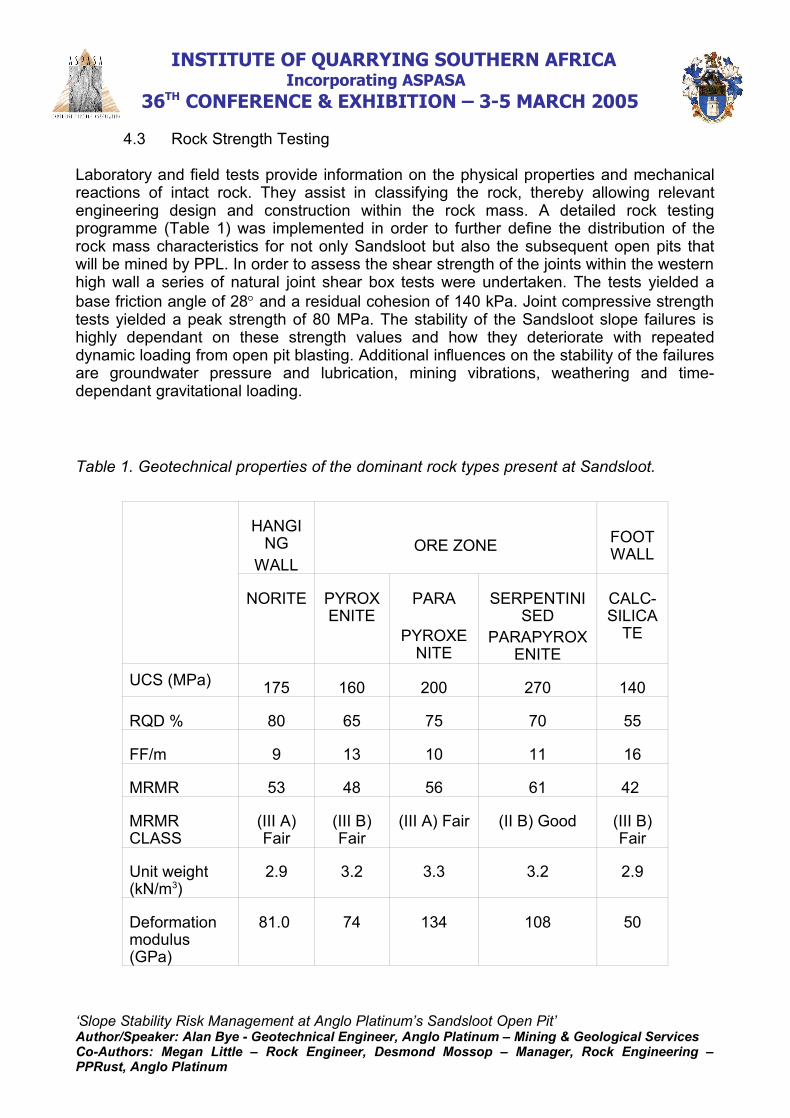
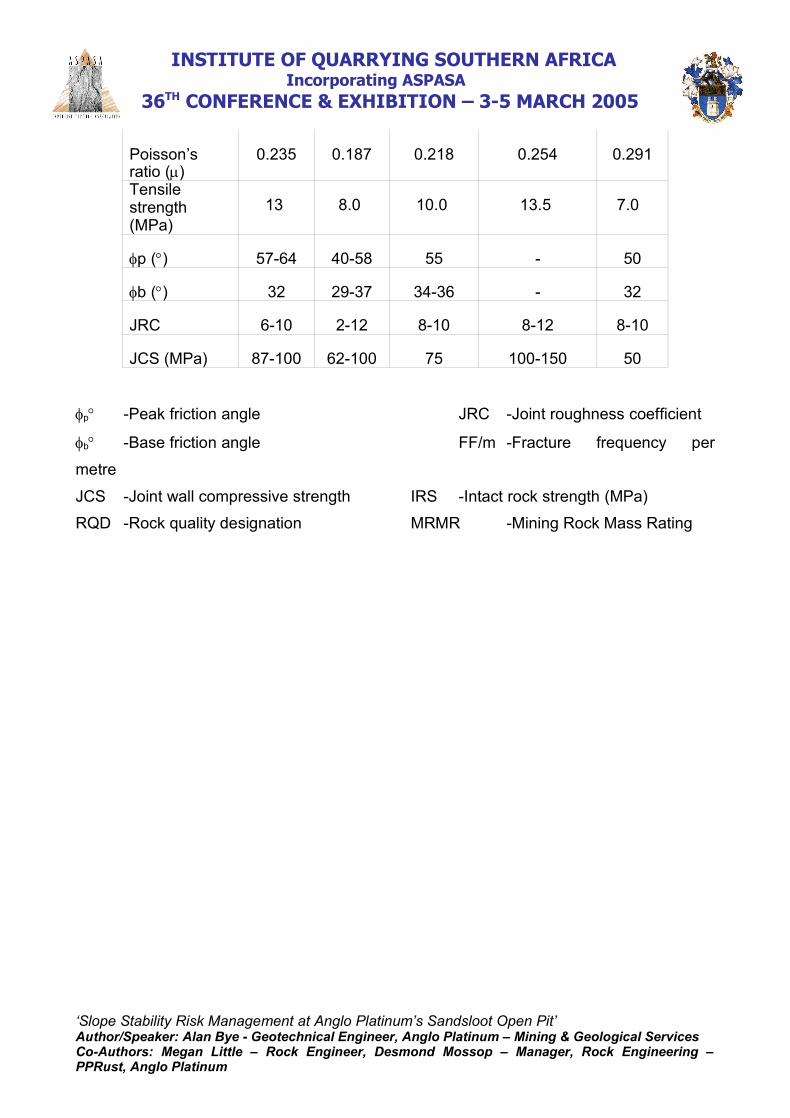
Laboratory and field tests provide information on the physical properties and mechanicalreactions of intact rock. They assist in classifying the rock, thereby allowing relevantengineering design and construction within the rock mass. A detailed rock testingprogramme (Table 1) was implemented in order to further define the distribution of therock mass characteristics for not only Sandsloot but also the subsequent open pits thatwill be mined by PPL. In order to assess the shear strength of the joints within the westernhigh wall a series of natural joint shear box tests were undertaken. The tests yielded abase friction angle of 28 and a residual cohesion of 140 kPa. Joint compressive strengthtests yielded a peak strength of 80 MPa. The stability of the Sandsloot slope failures ishighly dependant on these strength values and how they deteriorate with repeateddynamic loading from open pit blasting. Additional influences on the stability of the failuresare groundwater pressure and lubrication, mining vibrations, weathering and time-dependant gravitational loading.
Table 1. Geotechnical properties of the dominant rock types present at Sandsloot.
HANGING
WALLORE ZONE FOOT
WALL
NORITE PYROXENITE
PARA
PYROXENITE
SERPENTINISED
PARAPYROXENITE
CALC-SILICA
TE
UCS (MPa) 175 160 200 270 140
RQD % 80 65 75 70 55
FF/m 9 13 10 11 16
MRMR 53 48 56 61 42
MRMRCLASS
(III A)Fair
(III B)Fair
(III A) Fair (II B) Good (III B)Fair
Unit weight(kN/m3)
2.9 3.2 3.3 3.2 2.9
Deformationmodulus(GPa)
81.0 74 134 108 50
‘Slope Stability Risk Management at Anglo Platinum’s Sandsloot Open Pit’Author/Speaker: Alan Bye - Geotechnical Engineer, Anglo Platinum – Mining & Geological ServicesCo-Authors: Megan Little – Rock Engineer, Desmond Mossop – Manager, Rock Engineering –PPRust, Anglo Platinum
INSTITUTE OF QUARRYING SOUTHERN AFRICA Incorporating ASPASA
36TH CONFERENCE & EXHIBITION – 3-5 MARCH 2005
Poisson’sratio ()
0.235 0.187 0.218 0.254 0.291
Tensilestrength(MPa)
13 8.0 10.0 13.5 7.0
p () 57-64 40-58 55 - 50
b () 32 29-37 34-36 - 32
JRC 6-10 2-12 8-10 8-12 8-10
JCS (MPa) 87-100 62-100 75 100-150 50
p -Peak friction angle JRC -Joint roughness coefficient
b -Base friction angle FF/m -Fracture frequency per
metre
JCS -Joint wall compressive strength IRS -Intact rock strength (MPa)
RQD -Rock quality designation MRMR -Mining Rock Mass Rating
‘Slope Stability Risk Management at Anglo Platinum’s Sandsloot Open Pit’Author/Speaker: Alan Bye - Geotechnical Engineer, Anglo Platinum – Mining & Geological ServicesCo-Authors: Megan Little – Rock Engineer, Desmond Mossop – Manager, Rock Engineering –PPRust, Anglo Platinum

INSTITUTE OF QUARRYING SOUTHERN AFRICA Incorporating ASPASA
36TH CONFERENCE & EXHIBITION – 3-5 MARCH 2005
5 SLOPE DESIGN
5.1 Failure Mechanism Analysis
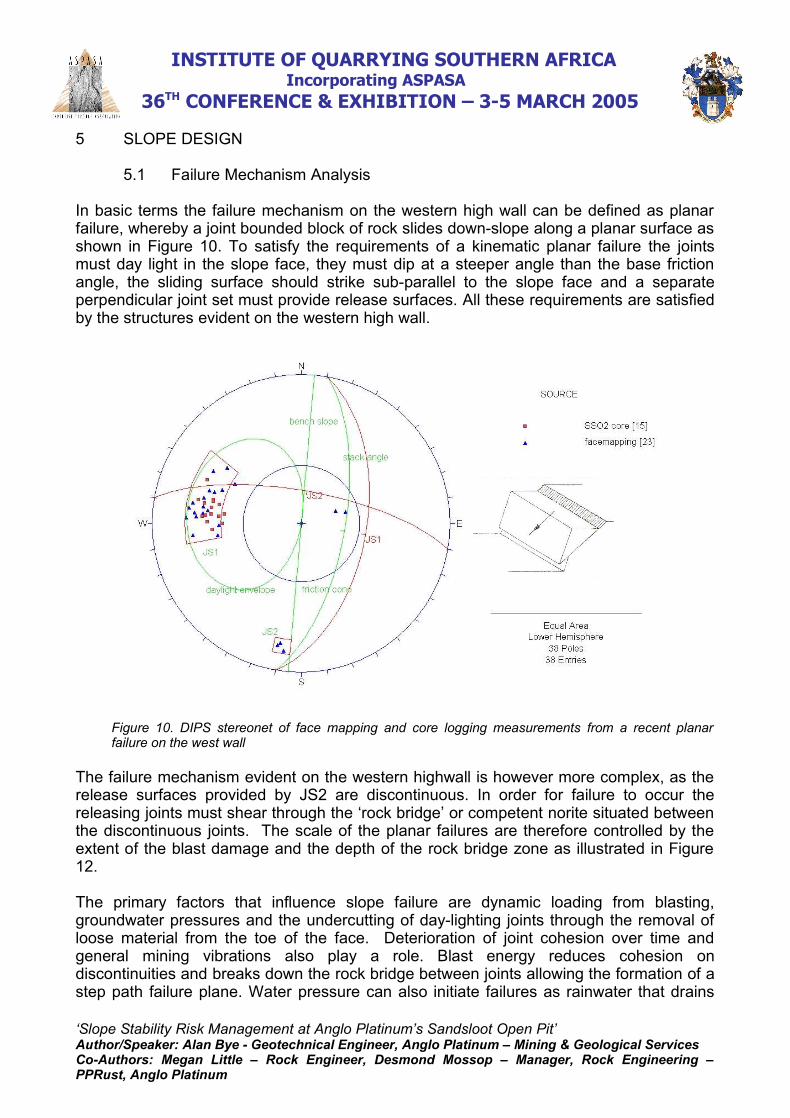
In basic terms the failure mechanism on the western high wall can be defined as planarfailure, whereby a joint bounded block of rock slides down-slope along a planar surface asshown in Figure 10. To satisfy the requirements of a kinematic planar failure the jointsmust day light in the slope face, they must dip at a steeper angle than the base frictionangle, the sliding surface should strike sub-parallel to the slope face and a separateperpendicular joint set must provide release surfaces. All these requirements are satisfiedby the structures evident on the western high wall.
Figure 10. DIPS stereonet of face mapping and core logging measurements from a recent planarfailure on the west wall
The failure mechanism evident on the western highwall is however more complex, as therelease surfaces provided by JS2 are discontinuous. In order for failure to occur thereleasing joints must shear through the ‘rock bridge’ or competent norite situated betweenthe discontinuous joints. The scale of the planar failures are therefore controlled by theextent of the blast damage and the depth of the rock bridge zone as illustrated in Figure12.
The primary factors that influence slope failure are dynamic loading from blasting,groundwater pressures and the undercutting of day-lighting joints through the removal ofloose material from the toe of the face. Deterioration of joint cohesion over time andgeneral mining vibrations also play a role. Blast energy reduces cohesion ondiscontinuities and breaks down the rock bridge between joints allowing the formation of astep path failure plane. Water pressure can also initiate failures as rainwater that drains
‘Slope Stability Risk Management at Anglo Platinum’s Sandsloot Open Pit’Author/Speaker: Alan Bye - Geotechnical Engineer, Anglo Platinum – Mining & Geological ServicesCo-Authors: Megan Little – Rock Engineer, Desmond Mossop – Manager, Rock Engineering –PPRust, Anglo Platinum
INSTITUTE OF QUARRYING SOUTHERN AFRICA Incorporating ASPASA
36TH CONFERENCE & EXHIBITION – 3-5 MARCH 2005
into JS1 faults and joints resulting in a base pressure at the toe of the failure planes. Thewater also lubricates the clay in-fill material. Undercutting also plays a role in inducingfailure. The shovel or back-hoe removes the support and gravity initiates failure. Thedelay between the undercutting and the failure is dependant on how much rock bridgethere is to shear through and how much cohesion there is on the plane.
5.2 Pit Design
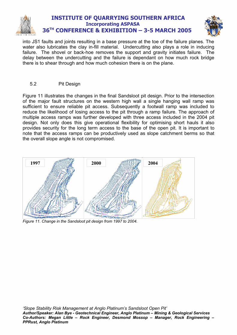
Figure 11 illustrates the changes in the final Sandsloot pit design. Prior to the intersectionof the major fault structures on the western high wall a single hanging wall ramp wassufficient to ensure reliable pit access. Subsequently a footwall ramp was included toreduce the likelihood of losing access to the pit through a ramp failure. The approach ofmultiple access ramps was further developed with three access included in the 2004 pitdesign. Not only does this give operational flexibility for optimising short hauls it alsoprovides security for the long term access to the base of the open pit. It is important tonote that the access ramps can be productively used as slope catchment berms so thatthe overall slope angle is not compromised.
Figure 11. Change in the Sandsloot pit design from 1997 to 2004.
‘Slope Stability Risk Management at Anglo Platinum’s Sandsloot Open Pit’Author/Speaker: Alan Bye - Geotechnical Engineer, Anglo Platinum – Mining & Geological ServicesCo-Authors: Megan Little – Rock Engineer, Desmond Mossop – Manager, Rock Engineering –PPRust, Anglo Platinum
1997 2000 2004
INSTITUTE OF QUARRYING SOUTHERN AFRICA Incorporating ASPASA
36TH CONFERENCE & EXHIBITION – 3-5 MARCH 2005
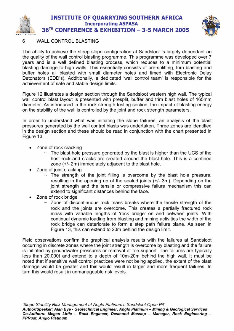
6 WALL CONTROL BLASTING
The ability to achieve the steep slope configuration at Sandsloot is largely dependant onthe quality of the wall control blasting programme. This programme was developed over 7years and is a well defined blasting process, which reduces to a minimum potentialblasting damage to high walls. This essentially consists of pre-splitting, trim blasting andbuffer holes all blasted with small diameter holes and timed with Electronic DelayDetonators (EDD’s). Additionally, a dedicated ‘wall control team’ is responsible for theachievement of safe and stable design limits.
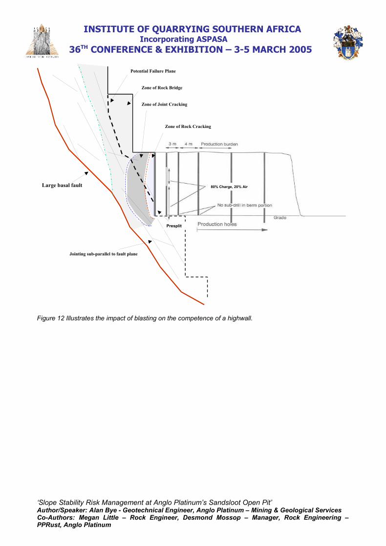
Figure 12 illustrates a design section through the Sandsloot western high wall. The typicalwall control blast layout is presented with presplit, buffer and trim blast holes of 165mmdiameter. As introduced in the rock strength testing section, the impact of blasting energyon the stability of the wall is controlled by the joint and rock strength parameters.
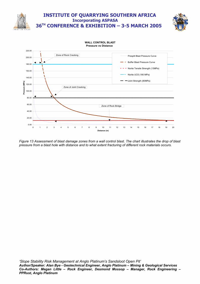
In order to understand what was initiating the slope failures, an analysis of the blastpressures generated by the wall control blasts was undertaken. Three zones are identifiedin the design section and these should be read in conjunction with the chart presented inFigure 13.
Zone of rock cracking~ The blast hole pressure generated by the blast is higher than the UCS of the
host rock and cracks are created around the blast hole. This is a confinedzone (+/- 2m) immediately adjacent to the blast hole.
Zone of joint cracking~ The strength of the joint filling is overcome by the blast hole pressure,
resulting in the opening up of the sealed joints (+/- 3m). Depending on thejoint strength and the tensile or compressive failure mechanism this canextend to significant distances behind the face.
Zone of rock bridge~ Zone of discontinuous rock mass breaks where the tensile strength of the
rock and the joints are overcome. This creates a partially fractured rockmass with variable lengths of ‘rock bridge’ on and between joints. Withcontinual dynamic loading from blasting and mining activities the width of therock bridge can deteriorate to form a step path failure plane. As seen inFigure 13, this can extend to 20m behind the design limit.
Field observations confirm the graphical analysis results with the failures at Sandslootoccurring in discrete zones where the joint strength is overcome by blasting and the failureis initiated by groundwater pressures or removal of toe support. The failures are typicallyless than 20,000t and extend to a depth of 10m-20m behind the high wall. It must benoted that if sensitive wall control practices were not being applied, the extent of the blastdamage would be greater and this would result in larger and more frequent failures. Inturn this would result in unmanageable risk levels.
‘Slope Stability Risk Management at Anglo Platinum’s Sandsloot Open Pit’Author/Speaker: Alan Bye - Geotechnical Engineer, Anglo Platinum – Mining & Geological ServicesCo-Authors: Megan Little – Rock Engineer, Desmond Mossop – Manager, Rock Engineering –PPRust, Anglo Platinum
INSTITUTE OF QUARRYING SOUTHERN AFRICA Incorporating ASPASA
36TH CONFERENCE & EXHIBITION – 3-5 MARCH 2005
Large basal fault
Jointing sub-parallel to fault plane
Zone of Rock Cracking
Zone of Joint Cracking
Zone of Rock Bridge
Potential Failure Plane
80% Charge, 20% Air
Presplit
Figure 12 Illustrates the impact of blasting on the competence of a highwall.
‘Slope Stability Risk Management at Anglo Platinum’s Sandsloot Open Pit’Author/Speaker: Alan Bye - Geotechnical Engineer, Anglo Platinum – Mining & Geological ServicesCo-Authors: Megan Little – Rock Engineer, Desmond Mossop – Manager, Rock Engineering –PPRust, Anglo Platinum
INSTITUTE OF QUARRYING SOUTHERN AFRICA Incorporating ASPASA
36TH CONFERENCE & EXHIBITION – 3-5 MARCH 2005
WALL CONTROL BLASTPressure vs Distance
0.00
20.00
40.00
60.00
80.00
100.00
120.00
140.00
160.00
180.00
200.00
220.00
0 1 2 3 4 5 6 7 8 9 10 11 12 13 14 15 16 17 18 19 20
Distance (m)
Pres
sure
(MPa
)
Presplit Blast Pressure Curve
Buffer Blast Pressure Curve
Norite Tensile Strength (13MPa)
Norite UCS (180 MPa)
Joint Strength (80MPa)
Zone of Rock Cracking
Zone of Joint Cracking
Zone of Rock Bridge
Figure 13 Assessment of blast damage zones from a wall control blast. The chart illustrates the drop of blastpressure from a blast hole with distance and to what extent fracturing of different rock materials occurs.
‘Slope Stability Risk Management at Anglo Platinum’s Sandsloot Open Pit’Author/Speaker: Alan Bye - Geotechnical Engineer, Anglo Platinum – Mining & Geological ServicesCo-Authors: Megan Little – Rock Engineer, Desmond Mossop – Manager, Rock Engineering –PPRust, Anglo Platinum
INSTITUTE OF QUARRYING SOUTHERN AFRICA Incorporating ASPASA
36TH CONFERENCE & EXHIBITION – 3-5 MARCH 2005
7 FAULT TREE ANALYSIS
7.1 Introduction
A fault tree is a graphical framework that is used to account for undesirable events (e.gfatality, damage to equipment, economic loss) and estimate their probabilities ofoccurrence (Anon., 1999). The framework illustrates the sequence of events that lead tothe undesirable event, including all their possible outcomes and assign probabilities ofoccurrence to each event. It is a powerful tool as it highlights where the problems are andhow one can reduce the risk of an event as serious as a fatality. The fault tree quantifiesthe risk and enables management to make informed decisions on the level of risk they arewilling to operate at.
7.2 Sandsloot Framework
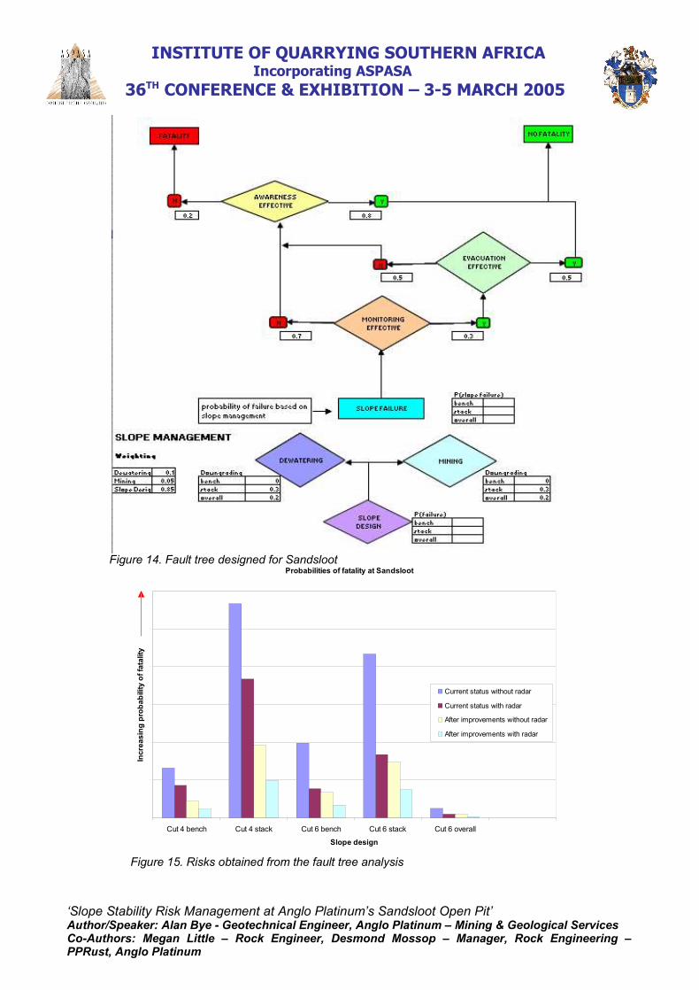
At Sandsloot, a fault tree analysis was done in order to quantify the risks posed by thefailures on the western high wall. The fault trees were designed to calculate theprobability of a fatality, which was then compared to the international acceptable level ofrisk (Figure 14). Failure on a bench, stack and overall slope was used as the rootcause/event and the design probabilities of failure assigned. The design probabilities,calculated from Slide (RocScience, 2003) and kinematic failure analysis, were adjusted totake into account operational conditions, such as wet slopes and the impact of blasting.Risk mitigation measures the effectiveness of monitoring, personnel awareness andevacuation in response to a failure was incorporated in the fault tree and personnelexposure to the failure incorporated to produce an overall probability of fatality.
7.3 Results
Various fault tree scenarios were run to determine the effect that improved monitoringtechniques as well as improved awareness, evacuation, dewatering and wall control wouldhave on mitigating risk to personnel at Sandsloot. In particular, the effect of theGroundProbe slope stability radar was studied. Bench, stack and overall slopes for thecurrent Cut 4 as well as the final Cut 6 designs were analysed. Results from the analysisshow that failure on a bench and especially stack scale are the highest risk in Sandsloot.The slope stability radar significantly reduced the safety risk thereby allowing operationsto continue within internationally accepted safety standards (Figure 15). Otherimprovements such as training, slope design configuration, operations work procedures,awareness, evacuation drills and slope dewatering also have a large effect on reducingrisk and are an essential part of the risk management programme.
‘Slope Stability Risk Management at Anglo Platinum’s Sandsloot Open Pit’Author/Speaker: Alan Bye - Geotechnical Engineer, Anglo Platinum – Mining & Geological ServicesCo-Authors: Megan Little – Rock Engineer, Desmond Mossop – Manager, Rock Engineering –PPRust, Anglo Platinum
INSTITUTE OF QUARRYING SOUTHERN AFRICA Incorporating ASPASA
36TH CONFERENCE & EXHIBITION – 3-5 MARCH 2005
Figure 14. Fault tree designed for Sandsloot Probabilities of fatality at Sandsloot
0 %
2 0 %
4 0 %
6 0 %
8 0 %
1 0 0 %
1 2 0 %
Cut 4 bench Cut 4 stack Cut 6 bench Cut 6 stack Cut 6 overall
Slope design
Incr
easi
ng p
roba
bilit
y of
fata
lity
Current status without radar
Current status with radar
After improvements without radar
After improvements with radar
Figure 15. Risks obtained from the fault tree analysis
‘Slope Stability Risk Management at Anglo Platinum’s Sandsloot Open Pit’Author/Speaker: Alan Bye - Geotechnical Engineer, Anglo Platinum – Mining & Geological ServicesCo-Authors: Megan Little – Rock Engineer, Desmond Mossop – Manager, Rock Engineering –PPRust, Anglo Platinum
INSTITUTE OF QUARRYING SOUTHERN AFRICA Incorporating ASPASA
36TH CONFERENCE & EXHIBITION – 3-5 MARCH 2005
8 SLOPE MONITORING STRATEGY
As discussed in the previous sections a great deal of time was spent on understandingthe failure mechanisms at Sandsloot, what initiates failure and the resultant risk levels.This information enabled the appropriate selection of slope monitoring or riskmanagement tools.
The slope monitoring tools were selected to provide early warning in a congested pitcontaining brittle slope failures. Owning to the short time to failure the monitoring wouldneed to provide as near to real time information as possible. The equipment would alsoneed to be mobile and have good resolution to detect the small scale failures. Thefollowing strategy was selected:
Long term~ The ISSI seismic monitoring system was installed to detect vibrations
caused by movement and cracking on major fault planes. The frequency ofvibrations are assessed on a monthly basis. The system is suited todetecting large scale failures and is still under trial.
Medium term~ Conventional survey monitoring of prisms installed on a 50m x 45m grid.
The monitoring is done by the GeoMoS system, which consists of automatictotal stations positioned on the crest of both the eastern and the westernhigh walls at Sandsloot. Each one covers half of the pit walls on a 24-hourbasis and is configured to measure all the prisms every 3 hours. A sms issent to the relevant staff when excessive movement, determined bygeotechnical staff, occurs. A computer dedicated to GeoMoS is set up inthe Survey office where the data can be viewed and plotted ondisplacement, velocity and vector graphs.
Short term~ Identified problem areas are equipped with crack meters and regular field
inspections highlight the deterioration of these areas. ~ Daily visual inspection of all active mining faces by geotechnical and
operations staff, which identifies areas of concern and poor groundconditions.
Real time~ A mobile, global monitoring system was required to detect and provide
warning of the small-scale brittle failures. The GroundProbe slope stabilityradar was ideally suited to this task.
‘Slope Stability Risk Management at Anglo Platinum’s Sandsloot Open Pit’Author/Speaker: Alan Bye - Geotechnical Engineer, Anglo Platinum – Mining & Geological ServicesCo-Authors: Megan Little – Rock Engineer, Desmond Mossop – Manager, Rock Engineering –PPRust, Anglo Platinum
INSTITUTE OF QUARRYING SOUTHERN AFRICA Incorporating ASPASA
36TH CONFERENCE & EXHIBITION – 3-5 MARCH 2005
9 GROUNDPROBE SLOPE STABILITY RADAR
The GroundProbe slope stability radar (SSR) uses differential interferometry to measuresub-millimetre movements on a rock face. The SSR has a range of 50 - 850 m and anaccuracy of 0.2 mm. It operates in all weather conditions, 24 hours a day and it scans thechosen area of the high wall roughly every ten minutes. A 2-dimensional deformationimage is produced and any number of deformation plots can be drawn at user-specifiedlocations in the scanned area. It has customisable alarm settings and masking options ina user-friendly software programme. GroundProbe began leasing their first SSR unit in2002 in Australia where they currently have 7 operational units at various hard rock mines.The GroundProbe SSR was brought to Sandsloot on an initial 2 month contract. The aimof the trial period was to determine whether the radar was able to measure and alertoperations personnel of the brittle slope failures in the pit.
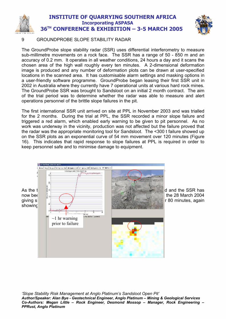
The first international SSR unit arrived on site at PPL in November 2003 and was trialledfor the 2 months. During the trial at PPL, the SSR recorded a minor slope failure andtriggered a red alarm, which enabled early warning to be given to pit personnel. As nowork was underway in the vicinity, production was not affected but the failure proved thatthe radar was the appropriate monitoring tool for Sandsloot. The <300 t failure showed upon the SSR plots as an exponential curve of 54 mm movement over 120 minutes (Figure16). This indicates that rapid response to slope failures at PPL is required in order tokeep personnel safe and to minimise damage to equipment.
Figure 16. SSR screen view with the deformation-over-time plot,photograph and deformation image of the <300 t brittle failure in Sandslootopen pit on 28th November 2003.
As the trial was successful, the lease with GroundProbe was extended and the SSR hasnow been on site for 8 months. Another larger failure was recorded on the 28 March 2004giving similar deformation plots as before with 300 mm movement over 80 minutes, againshowing the limited warning to failures (Figure 17 and 18).
‘Slope Stability Risk Management at Anglo Platinum’s Sandsloot Open Pit’Author/Speaker: Alan Bye - Geotechnical Engineer, Anglo Platinum – Mining & Geological ServicesCo-Authors: Megan Little – Rock Engineer, Desmond Mossop – Manager, Rock Engineering –PPRust, Anglo Platinum
~1 hr warningprior to failure
INSTITUTE OF QUARRYING SOUTHERN AFRICA Incorporating ASPASA
36TH CONFERENCE & EXHIBITION – 3-5 MARCH 2005
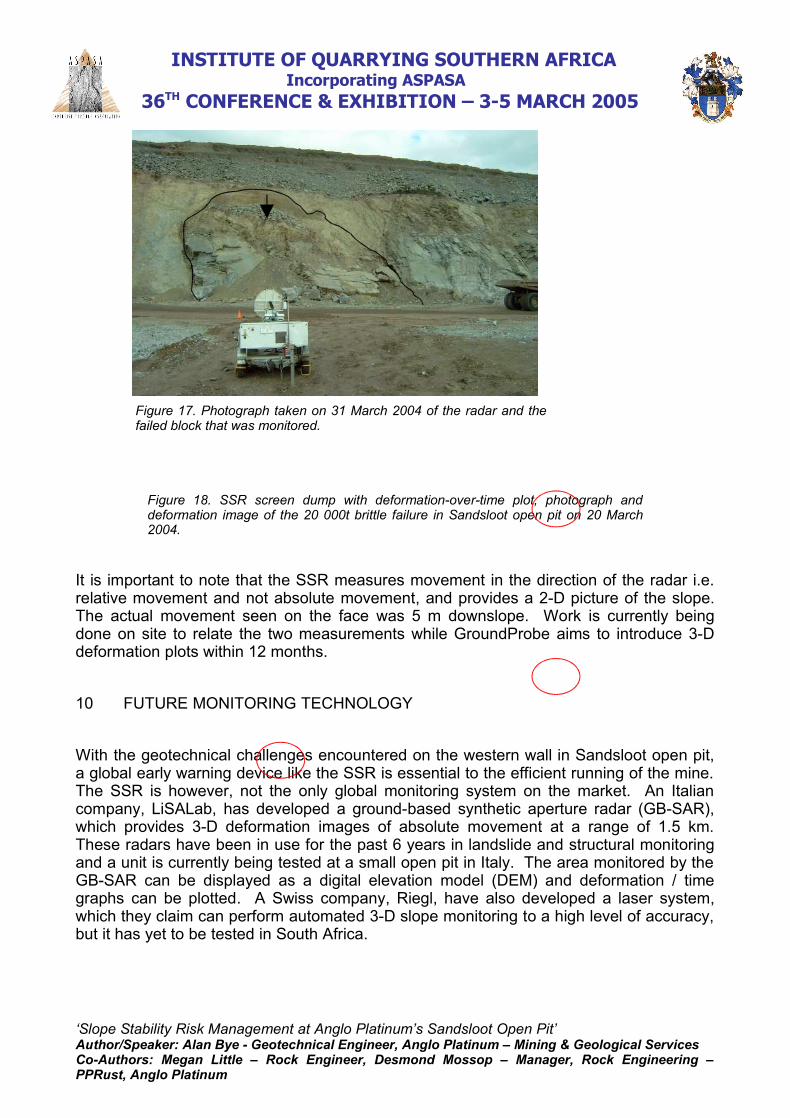
Figure 17. Photograph taken on 31 March 2004 of the radar and thefailed block that was monitored.
Figure 18. SSR screen dump with deformation-over-time plot, photograph anddeformation image of the 20 000t brittle failure in Sandsloot open pit on 20 March2004.
It is important to note that the SSR measures movement in the direction of the radar i.e.relative movement and not absolute movement, and provides a 2-D picture of the slope.The actual movement seen on the face was 5 m downslope. Work is currently beingdone on site to relate the two measurements while GroundProbe aims to introduce 3-Ddeformation plots within 12 months.
10 FUTURE MONITORING TECHNOLOGY
With the geotechnical challenges encountered on the western wall in Sandsloot open pit,a global early warning device like the SSR is essential to the efficient running of the mine.The SSR is however, not the only global monitoring system on the market. An Italiancompany, LiSALab, has developed a ground-based synthetic aperture radar (GB-SAR),which provides 3-D deformation images of absolute movement at a range of 1.5 km.These radars have been in use for the past 6 years in landslide and structural monitoringand a unit is currently being tested at a small open pit in Italy. The area monitored by theGB-SAR can be displayed as a digital elevation model (DEM) and deformation / timegraphs can be plotted. A Swiss company, Riegl, have also developed a laser system,which they claim can perform automated 3-D slope monitoring to a high level of accuracy,but it has yet to be tested in South Africa.
‘Slope Stability Risk Management at Anglo Platinum’s Sandsloot Open Pit’Author/Speaker: Alan Bye - Geotechnical Engineer, Anglo Platinum – Mining & Geological ServicesCo-Authors: Megan Little – Rock Engineer, Desmond Mossop – Manager, Rock Engineering –PPRust, Anglo Platinum
INSTITUTE OF QUARRYING SOUTHERN AFRICA Incorporating ASPASA
36TH CONFERENCE & EXHIBITION – 3-5 MARCH 2005
The GroundProbe SSR in conjunction with the conventional prism monitoring, visual faceinspections, piezometers and water level monitoring, extensometers as well as the ISSIseismic system, which measures micro-seismic movement within the slope, provide acomprehensive slope monitoring programme at Sandsloot. Extending the ISSI systemand trialling the LiSALab and Riegl systems are the next steps in ensuring the personnelat PPL are provided with the best possible early warning technology at reasonable prices.
SiroVision is a software package used for mapping by digital photogrammetry. It enablesmapping to be done rapidly and from a safe distance to unstable high walls. One canidentify joints, measure their dip and dip direction and plot them in 3-dimensional spaceon pit plans and slope configurations. It was trialled at Sandsloot and found to be an idealmapping tool for the ubiquitous joints on the western high wall.
11 CONCLUSION
The purpose of this paper was to document through a proven case study the knowledgecollected from the application of the slope stability risk management strategy. Thedescribed procedures will hopefully assist greenfield and existing operations with selectingthe appropriate slope management strategy.
Extensive fieldwork was conducted to collect geotechnical information and the detailedunderstanding was fundamental to the optimal design process undertaken. Significanttime was dedicated to understanding and back analysing the failure mechanism on thewestern high wall. This was critical for the appropriate mine design and selection ofmonitoring tools
The use of probability fault trees enabled the selection of the most appropriate mitigatingrisk measures and comparison with internationally accepted risk levels. The fault treequantifies the risk and enables management to make informed decisions on the level ofrisk they are willing to operate at.
The impact of the blast pressures on the joint filling was analysed to determine the depthsof damage and therefore expected failure volumes. Blast hole pressure versus distancecurves were analysed in order to assist with understanding the failure mechanism. Basedon the potential blast damage zones and the intersection of the major west wallstructures, areas of potential failure can be identified.
As part of the risk management strategy the monitoring systems at Sandsloot wereselected based on long, medium, short and real time monitoring requirements. Theapplication of the GroundProbe SSR at PPL has proven very successful and the initial trialperiod has been extended for the duration of 2004. With the geotechnical challengespresented by the western high wall in both open pits, a global, early warning device likethe SSR is a powerful operational tool for the safe and efficient operation of the mine.
‘Slope Stability Risk Management at Anglo Platinum’s Sandsloot Open Pit’Author/Speaker: Alan Bye - Geotechnical Engineer, Anglo Platinum – Mining & Geological ServicesCo-Authors: Megan Little – Rock Engineer, Desmond Mossop – Manager, Rock Engineering –PPRust, Anglo Platinum
INSTITUTE OF QUARRYING SOUTHERN AFRICA Incorporating ASPASA
36TH CONFERENCE & EXHIBITION – 3-5 MARCH 2005
The paper documents the procedures used to collect data, define the dominant failuremechanism, develop appropriate designs, assess the design risks using probability faulttrees and finally the implementation of a slope monitoring and wall control blastingstrategy to manage the failure risk. Figure 1.1 illustrates the risk management processfollowed at PPL. The process has been successfully applied with the appropriate level ofmonitoring and design, tailored to Sandsloot’s specific challenges.
12 REFERENCES
1. Cawthorn, R.G. 1996. Layered Intrusions. Elsevier Science, London.2. Friese, A. 2003. The structural geology of the PPL concession area, with
implications for the tectonic-magmatic evolution of the northern limb of theBushveld Igneous Complex. SRK Report No. 186322/2 October 2003.
3. Bye, A. R. and Bell, F. G. 2001. Stability assessment and slope design atSandsloot open pit, South Africa. International Journal of Rock Mechanics andMining Sciences. Pergamon, 38; 449-466.
4. Little, M.J. 2002. Development of a major feature plan and ramp stabilityanalysis at Sandsloot open pit, Limpopo Province, South Africa. B.Sc. Honoursdissertation (unpubl.), University of Cape Town, Cape Town, South Africa, 50pp.
5. RocScience Inc. 2003. Geomechanics software and research. 31 Balsam Ave.,Toronto, Ontario, Canada, M4E 3B5.
6. Anonymous. 1999. An overview of probabilistic analysis for geotechnicalengineering problems. Risk based analysis in geotechnical engineering forsupport of planning studies. US Army Core of Engineers.
‘Slope Stability Risk Management at Anglo Platinum’s Sandsloot Open Pit’Author/Speaker: Alan Bye - Geotechnical Engineer, Anglo Platinum – Mining & Geological ServicesCo-Authors: Megan Little – Rock Engineer, Desmond Mossop – Manager, Rock Engineering –PPRust, Anglo Platinum