Embed Size (px)
Citation preview
Slippery Rock Watershed Coalition Comprehensive Operation and Maintenance Plan
For Watershed Restoration Projects
March 2007
Prepared by BioMost, Inc. and Stream Restoration Incorporated
Funding Provided By A PA DEP Growing Greener Technical Assistance Grant
Slippery Rock Watershed Coalition March 2007 Comprehensive Operation & Maintenance Plan Stream Restoration Inc. & BioMost, Inc.
1
OPERATION AND MAINTENANCE PLAN
This document is the comprehensive operation and maintenance plan for abandoned mine restoration projects which have been completed by Slippery Rock Watershed Coalition (SRWC) participants through public-private partnership efforts. Passive treatment systems as well as land reclamation projects in the headwaters of the Slippery Rock Creek Watershed are included. The mine drainage treatment systems were designed and implemented based on the best available knowledge and technology at the time. The plan provides information about the features of the passive treatment systems and generalized instructions to successfully conduct site inspections and complete simple maintenance tasks. In addition, the plan contains site location maps, site schematics, and individualized inspection forms for each reclamation project. This plan has been developed so as to be user-friendly, whether a professional, a student, or a volunteer with little experience. Some training will be necessary for those unfamiliar with site inspection tasks and simple maintenance events. The SRWC participants maintain, on a volunteer basis, the passive systems in order to optimize long-term treatment of the abandoned mine drainage and to enhance wildlife habitat. All structures were designed focusing on minimal operation and maintenance compared to conventional chemical treatment systems. In order for these facilities to operate most effectively, however, periodic inspections and maintenance are required. As the technology of passively treating mine drainage is relatively new, improvements are expected to be developed to decrease operation and maintenance and to increase design life.
ACKNOWLEDGMENTS
This Operation and Maintenance Plan was completed through a public-private partnership effort under a Technical Assistance Grant awarded to Stream Restoration Incorporated through the Pennsylvania Department of Environmental Protection’s Growing Greener Program. Portions of this document were based upon an example provided by P. J. Shah of the Pennsylvania Department of Environmental Protection Bureau of Abandoned Mine Reclamation.
Public-Private Partnership Effort
241 Computer Services
Biomost, Inc. Environmentally Innovative Solutions, LLC Jennings Environmental Education Center
PA DEP, BAMR PA DEP, Grants Center
PA DEP, Knox DMO Quality Aggregates Inc.
Slippery Rock Watershed Coalition Stream Restoration Incorporated
Primary Author: Clifford F. Denholm, IV, Environmental Scientist Schematics: Shaun L. Busler, GISP Contributors: Timothy P. Danehy, QED; Kyle J. Durrett, Geo-technician; Tom Grote,
Education/Outreach; Sylvia Danehy, Administration; Margaret H. Dunn, PG
Slippery Rock Watershed Coalition March 2007 Comprehensive Operation & Maintenance Plan Stream Restoration Inc. & BioMost, Inc.
2
TABLE OF CONTENTS
SECTION PAGE
OVERVIEW OF AMD AND PASSIVE TREATMENT Historical Mining Impacts 4AMD Formation and Selected Monitoring Parameters 4 pH 5 Alkalinity; Acidity 6 Dissolved Oxygen; Sulfate; Specific Conductivity; Temperature 7 Oxidation/Reduction Potential; Total Suspended Solids; Total Dissolved Solids; Total Solids 8 Metals (iron, manganese, aluminum) 8AMD Treatment Chemistry 8Overview of Passive Treatment Components 10 Collection Systems 11 Forebays 11 Step-Aerators 11 Open Limestone Channels; Oxidation & Precipitation Channels 11 Anoxic Limestone Drains; Oxic Limestone Drains 12 Vertical Flow Ponds 12 Settling Ponds; Flush Ponds 13 Wetlands; Bioswales 13 Horizontal Flow Limestone Beds 14 Diversion Wells 14
GENERAL INSTRUCTIONS FOR MONITORING AND MAINTENANCE Field Equipment & Supplies 15Passive Treatment System O&M Inspection Report 16 A. Site Vegetation 17 B. Site Access and Parking 17 C. Vandalism and Housekeeping 17 D. Ditches, Channels, and Spillways 18 E. Culverts 18 F. Passive Treatment System Components 19 G. Wildlife Utilization 19 H. Flow Measurements 20 I. Field Water Monitoring and Sample Collection 23Sludge Accumulation Assessment Report 24Wetland Plant Diversity Report 24Flushing 25Miscellaneous Maintenance Considerations 26Replacement 27Datashed 27Site Inspection Schedule 29Sludge Accumulation Inspection Schedule 29
Slippery Rock Watershed Coalition March 2007 Comprehensive Operation & Maintenance Plan Stream Restoration Inc. & BioMost, Inc.
3
TABLE OF CONTENTS (Continued)
APPENDICIES
INDIVIDUAL SITE INSPECTION PLANS (All plans available online from Datashed)
BC 19 & 19B De Sale North De Sale Phase I De Sale Phase II De Sale Phase III Erico Bridge Ferris (SR85/86 & SR87/88) Passive Treatment Complex Goff Station Jennings North Liberty Reclamation Area – Phases I and II SR81 SR96 SR101A SR109 SR114B & 114D Sunbeam Tipple
GENERAL INSPECTION REPORTS Sludge Accumulation Assessment Report Wetland Plant Diversity Report
Slippery Rock Watershed Coalition March 2007 Comprehensive Operation & Maintenance Plan Stream Restoration Inc. & BioMost, Inc.
4
OVERVIEW OF AMD AND PASSIVE TREATMENT Historical Mining Impacts Coal has been mined in western Pennsylvania, as well as much of the Appalachian Coal Basin, for more than 200 years. During this time, this natural resource has played a pivotal role in the Industrial Revolution, resulting in the United States becoming a major world power. Despite the increasing development of alternative energy, coal continues to be vital to our way of life by generating over half of Pennsylvania’s (US as well) electricity. Electricity production alone accounts for over 90% of all the coal consumed in the US today. In addition, coal is used in iron- and steel-making processes and in the manufacture of chemicals, cement, glass, and paper, and in food processing. While this utilization of coal has fueled our homes, industries, and economy, the methods formerly used in coal extraction created a legacy of severe environmental impacts and public safety issues. Small towns and villages of western Pennsylvania and Appalachia, which were once bustling coal communities supporting the steel industry and electricity production for such cities as Pittsburgh (PA), Johnstown (PA), Wheeling (WV), New Castle (PA), and Youngstown (OH), are now often non-existent ghost towns left with only scarred landscapes characterized by dangerous highwalls, barren coal refuse piles, and, of course, degraded mine drainage. The degraded drainage from abandoned coal mines is the largest nonpoint source (diffuse sources; not a permitted discharge point) of stream impairment in Pennsylvania. According to the 2006 Pennsylvania Integrated Water Quality Monitoring and Assessment Report over 4,600 miles of streams are degraded. In addition, 45 of Pennsylvania’s 67 counties are impacted by over 250,000 acres of unreclaimed mine lands, including 2.6 billion cubic yards of coal refuse piles. Pennsylvania also has approximately 7,800 abandoned or inactive underground mines, which are typically the largest contributors of mine drainage. In many cases, entire watersheds have been completely decimated. The majority of stream degradation, however, appears to be related to historical mining. With knowledge of the cause, documentation of long-term stream impacts, development of environmentally-focused mining methods, and requirement of comprehensive permitting and oversight by enactment of the PA Surface Mining Conservation & Reclamation Act, Clean Streams Law, etc. and 1977 federal Surface Mining Control & Reclamation Act, 1% of modern operations have post-mining discharges requiring treatment. (PA DEP, 1999, Evaluation of Mining Permits Resulting in Acid Mine Drainage 1987-1996: A Post Mortem Study) AMD Formation and Selected Monitoring Parameters The following brief overview may be helpful to those unfamiliar with terms and concepts that are important in learning about mine drainage and passive treatment systems. This, however, should not be considered a comprehensive, authoritative, or complete undertaking. There are several parameters that are used to describe and characterize mine drainage. What is AMD? AMD is an acronym typically used for Abandoned Mine Drainage or Acid Mine Drainage, although AMD can be acidic or alkaline in nature and can emanate from abandoned or active mines. There are different names and acronyms for AMD that are used throughout the world such as Coal Mine Drainage (CMD), Mine Drainage (MD), and Acid Rock Drainage (ARD). In Pennsylvania, degraded coal mine drainage is usually referred to as AMD.
Slippery Rock Watershed Coalition March 2007 Comprehensive Operation & Maintenance Plan Stream Restoration Inc. & BioMost, Inc.
5
The formation of mine drainage is essentially a weathering process that is a function of the geology, chemistry, biology, hydrology, and mining methods used at the site. Although the specific process may vary, AMD forms through a series of complex geochemical and, at times, microbial reactions that occur when water and oxygen contact sulfide minerals such as pyrite (FeS2) which is typically present within coal and/or surrounding rock. The iron sulfide minerals “breakdown” (not unlike a nail rusting) in the presence of water and oxygen releasing iron and forming sulfuric acid. (Without the presence of water, oxygen, and sulfide minerals, AMD will most likely not form.) When the iron is further oxidized and hydrolyzed, iron compounds form and settle in ponds, wetlands, and streams. Due to the yellow, orange, and/or red color, these iron solids are often referred to as “Yellowboy”. Although there are a number of steps in the process, these reactions can be represented by the following general chemical equation:
(1) 4 FeS2 + 15 O2 + 14 H2O 4 Fe(OH)3 + 8 H2SO4 Pyrite + Oxygen + Water “Yellowboy” + Sulfuric Acid
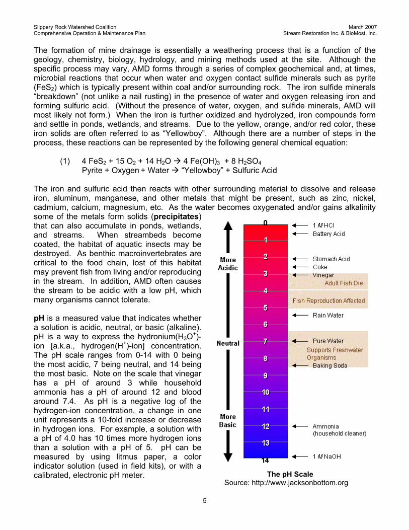
The iron and sulfuric acid then reacts with other surrounding material to dissolve and release iron, aluminum, manganese, and other metals that might be present, such as zinc, nickel, cadmium, calcium, magnesium, etc. As the water becomes oxygenated and/or gains alkalinity some of the metals form solids (precipitates) that can also accumulate in ponds, wetlands, and streams. When streambeds become coated, the habitat of aquatic insects may be destroyed. As benthic macroinvertebrates are critical to the food chain, lost of this habitat may prevent fish from living and/or reproducing in the stream. In addition, AMD often causes the stream to be acidic with a low pH, which many organisms cannot tolerate. pH is a measured value that indicates whether a solution is acidic, neutral, or basic (alkaline). pH is a way to express the hydronium(H3O+)-ion [a.k.a., hydrogen(H+)-ion] concentration. The pH scale ranges from 0-14 with 0 being the most acidic, 7 being neutral, and 14 being the most basic. Note on the scale that vinegar has a pH of around 3 while household ammonia has a pH of around 12 and blood around 7.4. As pH is a negative log of the hydrogen-ion concentration, a change in one unit represents a 10-fold increase or decrease in hydrogen ions. For example, a solution with a pH of 4.0 has 10 times more hydrogen ions than a solution with a pH of 5. pH can be measured by using litmus paper, a color indicator solution (used in field kits), or with a calibrated, electronic pH meter.
The pH Scale Source: http://www.jacksonbottom.org
Slippery Rock Watershed Coalition March 2007 Comprehensive Operation & Maintenance Plan Stream Restoration Inc. & BioMost, Inc.
6
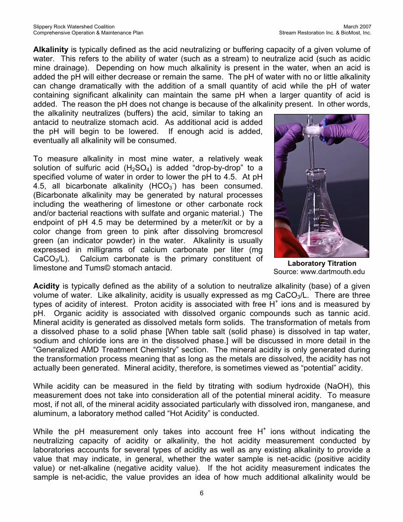
Alkalinity is typically defined as the acid neutralizing or buffering capacity of a given volume of water. This refers to the ability of water (such as a stream) to neutralize acid (such as acidic mine drainage). Depending on how much alkalinity is present in the water, when an acid is added the pH will either decrease or remain the same. The pH of water with no or little alkalinity can change dramatically with the addition of a small quantity of acid while the pH of water containing significant alkalinity can maintain the same pH when a larger quantity of acid is added. The reason the pH does not change is because of the alkalinity present. In other words, the alkalinity neutralizes (buffers) the acid, similar to taking an antacid to neutralize stomach acid. As additional acid is added the pH will begin to be lowered. If enough acid is added, eventually all alkalinity will be consumed. To measure alkalinity in most mine water, a relatively weak solution of sulfuric acid (H2SO4) is added “drop-by-drop” to a specified volume of water in order to lower the pH to 4.5. At pH 4.5, all bicarbonate alkalinity (HCO3
-) has been consumed. (Bicarbonate alkalinity may be generated by natural processes including the weathering of limestone or other carbonate rock and/or bacterial reactions with sulfate and organic material.) The endpoint of pH 4.5 may be determined by a meter/kit or by a color change from green to pink after dissolving bromcresol green (an indicator powder) in the water. Alkalinity is usually expressed in milligrams of calcium carbonate per liter (mg CaCO3/L). Calcium carbonate is the primary constituent of limestone and Tums© stomach antacid. Acidity is typically defined as the ability of a solution to neutralize alkalinity (base) of a given volume of water. Like alkalinity, acidity is usually expressed as mg CaCO3/L. There are three types of acidity of interest. Proton acidity is associated with free H+ ions and is measured by pH. Organic acidity is associated with dissolved organic compounds such as tannic acid. Mineral acidity is generated as dissolved metals form solids. The transformation of metals from a dissolved phase to a solid phase [When table salt (solid phase) is dissolved in tap water, sodium and chloride ions are in the dissolved phase.] will be discussed in more detail in the “Generalized AMD Treatment Chemistry” section. The mineral acidity is only generated during the transformation process meaning that as long as the metals are dissolved, the acidity has not actually been generated. Mineral acidity, therefore, is sometimes viewed as “potential” acidity. While acidity can be measured in the field by titrating with sodium hydroxide (NaOH), this measurement does not take into consideration all of the potential mineral acidity. To measure most, if not all, of the mineral acidity associated particularly with dissolved iron, manganese, and aluminum, a laboratory method called “Hot Acidity” is conducted. While the pH measurement only takes into account free H+ ions without indicating the neutralizing capacity of acidity or alkalinity, the hot acidity measurement conducted by laboratories accounts for several types of acidity as well as any existing alkalinity to provide a value that may indicate, in general, whether the water sample is net-acidic (positive acidity value) or net-alkaline (negative acidity value). If the hot acidity measurement indicates the sample is net-acidic, the value provides an idea of how much additional alkalinity would be
Laboratory Titration Source: www.dartmouth.edu
Slippery Rock Watershed Coalition March 2007 Comprehensive Operation & Maintenance Plan Stream Restoration Inc. & BioMost, Inc.
7
required to neutralize all of the potential acidity that could be generated by the oxidation and hydrolysis of most of the metals of concern. For instance, while a mine drainage sample could have a pH of 7, which would indicate that the water was neutral with no acidity, conducting a hot acidity test may reveal that metals dissolved in the water most likely to precipitate (given enough time and proper conditions) will produce acidity and actually result in the water being identified as a net-acidic. Dissolved Oxygen (DO) is the measurement of the amount of oxygen dissolved in the water. It is determined either chemically (Winkler or iodometric methods) or with an electronic meter and is expressed in mg/L. DO is very important for several reasons. DO is important to aquatic organisms within a body of water. If no oxygen is present, fish and other aquatic life will die. Different species require different levels. Trout, for example, need relatively high concentrations. DO is also important in the treatment of AMD, which will be discussed later. Several factors can affect DO concentrations including the physical environment (lake or stream, shaded or open, temperature, aeration) as well as chemical and biological processes that consume (chemical reactions, decomposition of organic material, respiration) or add (photosynthesis) dissolved oxygen within the body of water. Temperature is very important due to the major role in the solubility of oxygen within water. For example, more oxygen can be dissolved in cold water than warm water. Field experience suggests, however, that water capped by ice (such as, a frozen pond) may have much less oxygen. Sulfate (SO4
-2) is measured through a variety of laboratory techniques and instrumentation. Although commonly present in acid rain, concentrations of the dissolved sulfate ion of >50 mg/L usually indicate coal mine drainage in western Pennsylvania. As discussed earlier, the sulfate ion is present in mine water typically by the weathering (dissolving) of sulfide minerals. The sulfates may, in turn, be used to generate alkalinity as a by-product of the decomposition of organic material (such, as compost) by anaerobic (without oxygen) bacteria (known as sulfate-reducing bacteria). High sulfate and calcium concentrations may also result in the precipitation of the mineral gypsum (CaSO4•2H2O) which may cause plugging problems within the system. Specific Conductivity is used to measure the ability of water to carry an electrical current. This ability is dependent on several factors including the presence of ions and the temperature during measurement. Specific conductivity readings are automatically normalized to 25oC to essentially eliminate the variability related to temperature. Specific conductivity is typically measured by an electronic meter and is expressed in micromhos per centimeter (µmho/cm). Low values indicate fewer dissolved ions while larger values indicate a higher number of dissolved ions. Although a large value does not necessarily mean pollution or a specific type of pollution, larger values do indicate that any pollutants present may be dissolved as opposed to solids floating in the water or sediment in the sample from disturbing the streambed. Temperature, typically measured in either degrees Fahrenheit (oF) or Celsius (oC), is an important parameter affecting various physical as well as chemical processes. As previously discussed, temperature affects the solubility of dissolved oxygen and also the activity of certain organisms such as reptiles. Temperatures can even be used to indicate the source of pollution. For instance, a groundwater source can be distinguished from a surface water source as the groundwater is typically warmer in winter and cooler in summer compared to surface water.
Slippery Rock Watershed Coalition March 2007 Comprehensive Operation & Maintenance Plan Stream Restoration Inc. & BioMost, Inc.
8
Oxidation/Reduction Potential (ORP) is measured in millivolts (mV) using an ORP meter. The higher the value above zero, the more oxidizing the water, while the closer the value is to zero the more reducing. A value below zero is reducing. In AMD, high ORP values in water having a pH <3.5 may reflect the presence of high concentrations of dissolved ferric iron (Fe+3). Total Suspended Solids (TSS) is the measurement of the amount of solids within a given volume of water, retained when passed through a certain pore-size filter. Typically, a 0.45-µm pore-size filter is used. Total Dissolved Solids (TDS) are the portion that passes through the filter. Total Solids, which includes both TSS and TDS, are usually measured by evaporating a water sample and then drying and weighing the remaining residue. Metals, most commonly monitored in mine drainage are iron (Fe), manganese (Mn), and aluminum (Al). Measurements are often performed by an analytical laboratory using Atomic Absorption (AA), Spectrophotometry, or Inductively Coupled Plasma (ICP). While not necessarily as accurate as the laboratory methods, iron, manganese, and aluminum concentrations can also be measured using certain field kits. Iron solids give mine drainage that typical red or orange color while aluminum solids are white in color. Aluminum solids can also give water a bright aquamarine blue color. Manganese solids have a dark brown or black color. Iron often coats the streambed suffocating the benthic macroinvertebrates resulting in the destruction of the food chain. Aluminum can clog the gills of fish and macroinvertebrates. Of the three, aluminum generates more mineral acidity per unit concentration. Manganese at typical concentrations has not been demonstrated to have significant ecological impact. Manganese can cause discoloration or impart a bad taste to drinking water. AMD Treatment Chemistry To make site inspections and water monitoring more meaningful, a brief review of some applicable chemical processes is helpful. Passive treatment of net-acid mine drainage essentially revolves around imparting alkalinity to mine drainage and then allowing (and possibly enhancing) natural chemical, biological, and physical processes to occur. Limestone is commonly used when passively treating acid mine drainage. Limestone, which occurs in many areas of western Pennsylvania, is rock that has at least 50% calcium carbonate (CaCO3). The Vanport limestone, which is used in the Slippery Rock Creek Watershed passive treatment systems, is about 90% calcium carbonate. In reaction (2), the calcium carbonate (usually in the mineral form as calcite) reacts with the hydrogen ion (H+) and produces bicarbonate alkalinity (HCO3
-) and calcium (Ca+2).
(2) CaCO3 + H+ Ca+2 + HCO3-
Limestone + Acidity (proton) Calcium + Bicarbonate Alkalinity Not only is acidity consumed, but alkalinity is generated. The bicarbonate ion then goes on to neutralize additional hydrogen ions (H+) in reaction (3), which results in the production of water and carbon dioxide (CO2). This is basically the same reaction that occurs in your stomach when you take an antacid such as the Tums©, which has calcium carbonate as the main ingredient. In an enclosed environment, the CO2 cannot escape (similar to a carbonated beverage in a can or bottle) and forms carbonic acid which makes the water more reactive resulting in more limestone being dissolved; thereby, allowing for more alkalinity to be generated.
Slippery Rock Watershed Coalition March 2007 Comprehensive Operation & Maintenance Plan Stream Restoration Inc. & BioMost, Inc.
9
(3) HCO3- + H+ H2O + CO2
Bicarbonate Alkalinity + Acidity (proton) Water + Carbon Dioxide Another potential source of alkalinity commonly used in passive treatment systems is bacterial sulfate reduction illustrated in reaction (4). As discussed previously, mine drainage contains sulfate ions. When the mine drainage comes into contact with organic matter in an anaerobic (no or very little oxygen present) environment certain bacteria can decompose or oxidize the organic matter using sulfates as an electron sink to form hydrogen sulfide gas (H2S) and bicarbonate (HCO3
-) alkalinity. (Iron sulfides may also be formed.) Hydrogen sulfide gas is a gas that has a rotten-egg smell which is often noticeable in wetlands and vertical flow ponds with compost or other organic matter that are under anaerobic conditions. In this reaction 2 moles of bicarbonate are created for every mole of sulfate consumed. Sulfate-reducing bacteria
(4) 2CH2O + SO4-2 H2S + 2HCO3
- Organic Matter + Sulfates Hydrogen Sulfide + Bicarbonate Alkalinity As the alkalinity generated by the passive treatment components begins to neutralize the acidity, the pH begins to increase and other chemical reactions begin to take place. Besides pH and acidity the major contaminants that are of concern are metals. During the formation of mine drainage, metals exist in a dissolved state. To remove the metals, solids are formed. The design of a passive treatment system is based upon considering the various biogeochemical and physical processes that remove these metals. As previously mentioned, the three major metals of concern in coal mine drainage are iron, manganese, and aluminum. Iron: The removal of iron can occur under multiple conditions and pathways. Dissolved iron may also exist in multiple valence states. (Valence deals with behavior of electrons; i.e., ferrous iron (Fe+2) is the reduced form of iron while ferric iron (Fe+3) is the oxidized form of iron with one less electron.) The most common state of dissolved iron in mine drainage is ferrous iron (Fe+2). Typically, except in the case of sulfides where sulfate-reducing bacteria are active, ferrous iron needs to be oxidized to ferric iron to be removed from the water. The oxidation of dissolved ferrous to dissolved ferric iron can occur with or without bacterial activity. Bacterial activity is important in mine water with low pH (<3.5) while dissolved oxygen (1 mg/L DO needed to oxidize 7 mg/L ferrous iron) is important in mine water at higher pH. Once oxidized ferric iron may be hydrolyzed (generally meaning reacts with water) to form the yellow to red-brown iron solids. At low pH, iron minerals may form that typically feel silty or are “crusty”. As these minerals do not need oxygen to form, plugging is a consideration when designing a passive system. Iron solids forming at a higher pH are amorphous and are typically “gooey” or slippery feeling. These solids are commonly collected in settling ponds and wetlands. Reaction rates appear to be strongly influenced by pH. The higher the pH, the faster the reactions take place. If alkalinity is present in the water, often the pH of the water can be raised by agitating the water to degas dissolved CO2 which suppresses pH. Agitating the water can be accomplished with step aerators, splashing, steep rock-lined spillways, etc. Also consider that when treating discharges with high concentrations of ferrous iron, dissolved oxygen is consumed; therefore, additional aeration steps are often required. Acidity is created as a result of the precipitation of iron.
Slippery Rock Watershed Coalition March 2007 Comprehensive Operation & Maintenance Plan Stream Restoration Inc. & BioMost, Inc.
10
Manganese: The removal of manganese is also challenging. Historically, removal of manganese has been difficult and for a period of time was thought to only be accomplished through chemical treatment by raising the pH above ~9. With the development of passive technology, dissolved manganese has been observed to form solids at a much lower pH (~6). The exact mechanism is not completely understood at this time, but biogeochemical factors such as low dissolved iron concentrations, high dissolved oxygen concentrations, available surface area, sufficient alkalinity, presence of certain microorganisms, and autocatalytic processes appear to play a significant role. Aluminum: As the solubility of aluminum is strongly dependant on the pH, once the pH is raised to about 4.5, aluminum begins to form solids and precipitate out of solution. [Dissolve aluminum (Al+3) is in the oxidized form; therefore, oxygen is not necessary to form solids.] By a pH of about 5, there is generally < 1 mg/L of dissolved aluminum present. The solids can then be collected in a settling pond or wetland. Recognizing this process becomes very important in choosing which passive component to use. Remember from the acidity discussion that the precipitation of dissolved metals, including aluminum, results in the release of hydrogen ions and thus the creation of acidity which can decrease pH. Sufficient additional alkalinity will need to be generated either prior to or after this reaction in order to neutralize the mineral acidity. Overview of Passive Treatment System Components Passive systems use no electricity, require limited maintenance, and use environmentally-friendly materials, such as limestone aggregate and spent mushroom compost in a series of constructed ponds, beds, ditches and wetlands to provide a cost-effective alternative to the conventional treatment of mine drainage which is labor and energy intensive and typically uses harsh chemicals. Passive systems add alkalinity to neutralize acidity while providing an environment suitable for beneficial chemical reactions and biological activity. For instance, dissolving limestone neutralizes the acidity and raises the pH after which dissolved metals, through chemical, biological, and physical processes, form particulates (solids) that are then retained in settling ponds and constructed wetlands. In some cases, however, there is sufficient alkalinity naturally in the mine discharge in which case only settling ponds and constructed wetlands are needed. When designing a passive system, the goal is to include components that provide long-term effective treatment, are economical to install, and require minimal maintenance. There are several main types of passive treatment components that can be used, often in series and/or in parallel, to treat degraded mine drainage. These components are chosen based upon the mine drainage characteristics (quality and flow rate), preferred chemical or biological process, and available construction space. The following is a brief description of the major passive treatment components utilized at different restoration projects. Every passive system is unique and, therefore, not all of the projects will have every type of component.
Slippery Rock Watershed Coalition March 2007 Comprehensive Operation & Maintenance Plan Stream Restoration Inc. & BioMost, Inc.
11
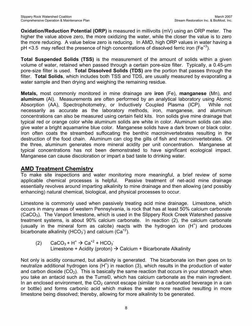
Collection Systems serve to collect, intercept, and/or combine discharges and seeps as well as to convey the drainage to the treatment component. A collection system can be as simple as a rock-lined channel or a more complex buried perforated piping system similar to a French drain or a dam with an intake pipe. Some collection systems are oxic (open to the atmosphere) while others are anoxic (buried or otherwise closed to the atmosphere) to inhibit oxygen from dissolving the water. Leaves, sediment, etc. may need to be removed from these components.
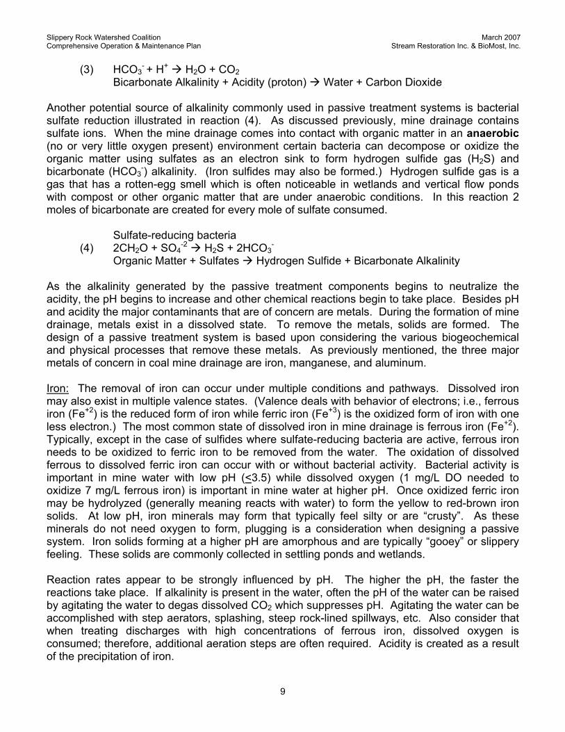
Forebays are open pond-like structures that are typically installed before a component that generates alkalinity. These components can serve multiple purposes, such as collecting, intercepting, combining, and/or conveying water, settling of debris such as sticks and leaves, and allowing oxidation, precipitation, and accumulation of metals solids. Inlets and outlets may occasionally need to be cleaned of debris.
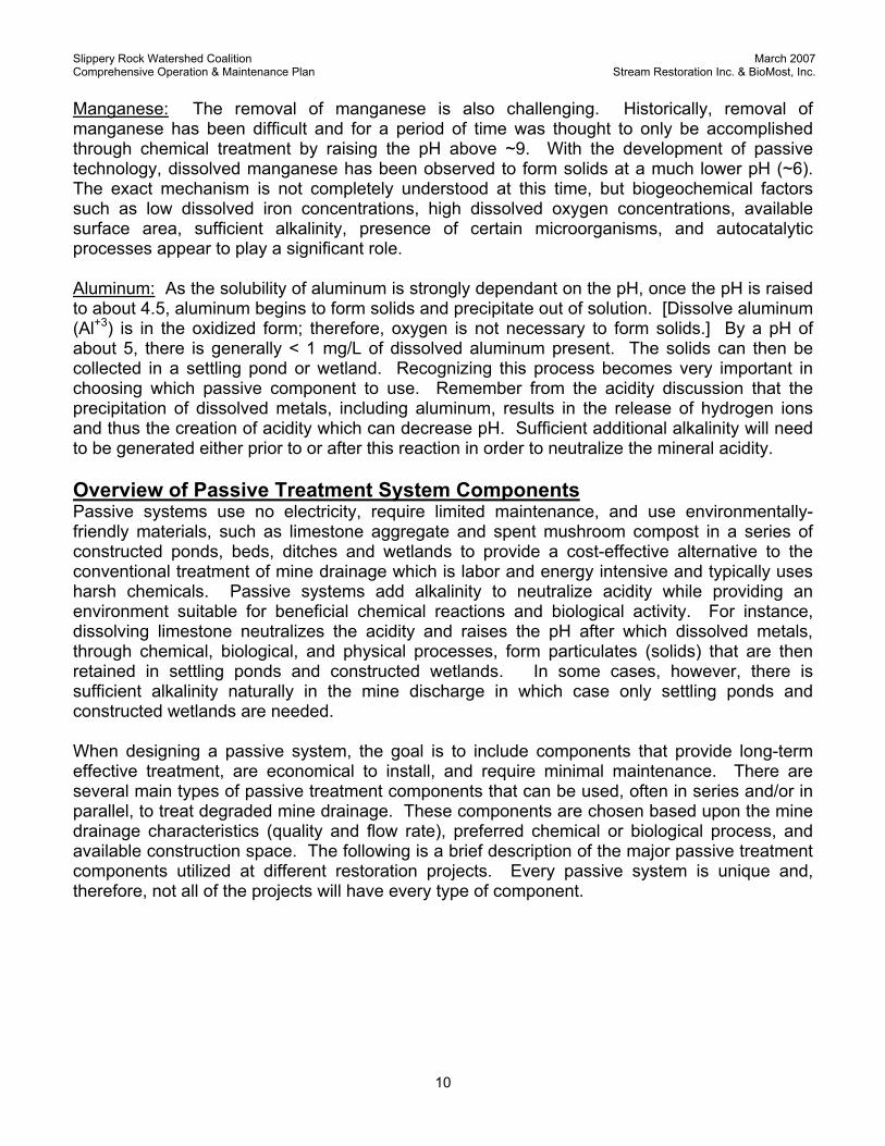
Step-Aerators (SA), which can be created using steep, rock-lined, channels or fabricated from a variety of materials such as concrete or corrosion-resistant stainless steel, often look like a set of stairs. Aerators are used for multiple functions including conveying and adding oxygen to the water, converting dissolved ferrous to dissolved ferric iron, and degassing dissolved carbon dioxide and hydrogen sulfide. Occasionally, step-aerators may need to be cleaned of metal sludge accumulations.
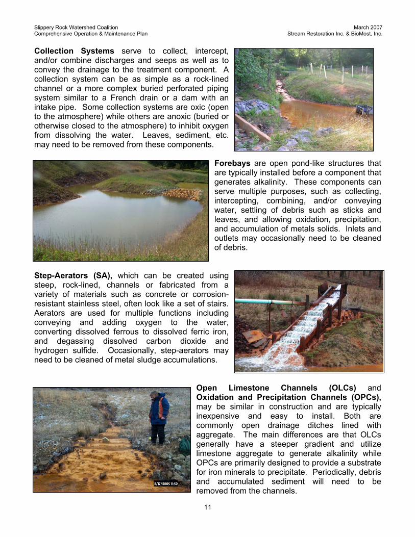
Open Limestone Channels (OLCs) and Oxidation and Precipitation Channels (OPCs), may be similar in construction and are typically inexpensive and easy to install. Both are commonly open drainage ditches lined with aggregate. The main differences are that OLCs generally have a steeper gradient and utilize limestone aggregate to generate alkalinity while OPCs are primarily designed to provide a substrate for iron minerals to precipitate. Periodically, debris and accumulated sediment will need to be removed from the channels.
Slippery Rock Watershed Coalition March 2007 Comprehensive Operation & Maintenance Plan Stream Restoration Inc. & BioMost, Inc.
12
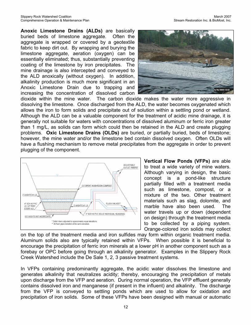
Anoxic Limestone Drains (ALDs) are basically buried beds of limestone aggregate. Often the aggregate is wrapped or covered by a geotextile fabric to keep dirt out. By wrapping and burying the limestone aggregate, aeration (oxygen) can be essentially eliminated; thus, substantially preventing coating of the limestone by iron precipitates. The mine drainage is also intercepted and conveyed to the ALD anoxically (without oxygen). In addition, alkalinity production is much more significant in an Anoxic Limestone Drain due to trapping and increasing the concentration of dissolved carbon dioxide within the mine water. The carbon dioxide makes the water more aggressive in dissolving the limestone. Once discharged from the ALD, the water becomes oxygenated which allows the iron to form solids and precipitate out of solution within a settling pond or wetland. Although the ALD can be a valuable component for the treatment of acidic mine drainage, it is generally not suitable for waters with concentrations of dissolved aluminum or ferric iron greater than 1 mg/L, as solids can form which could then be retained in the ALD and create plugging problems. Oxic Limestone Drains (OLDs) are buried, or partially buried, beds of limestone; however, the mine water and/or the limestone bed contain dissolved oxygen. Often OLDs will have a flushing mechanism to remove metal precipitates from the aggregate in order to prevent plugging of the component.
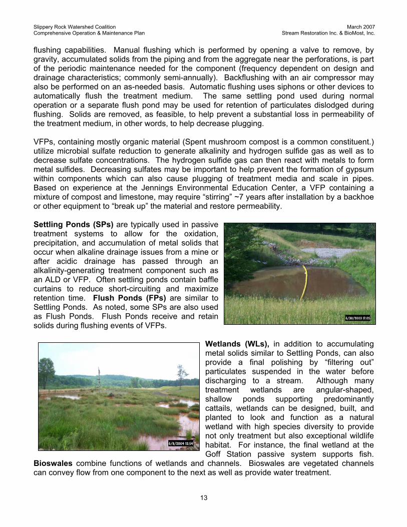
Vertical Flow Ponds (VFPs) are able to treat a wide variety of mine waters. Although varying in design, the basic concept is a pond-like structure partially filled with a treatment media such as limestone, compost, or a mixture of the two. Other treatment materials such as slag, dolomite, and marble have also been used. The water travels up or down (dependent on design) through the treatment media to be collected by a piping system. Orange-colored iron solids may collect
on the top of the treatment media and iron sulfides may form within organic treatment media. Aluminum solids also are typically retained within VFPs. When possible it is beneficial to encourage the precipitation of ferric iron minerals at a lower pH in another component such as a forebay or OPC before going through an alkalinity generator. Examples in the Slippery Rock Creek Watershed include the De Sale 1, 2, 3 passive treatment systems. In VFPs containing predominantly aggregate, the acidic water dissolves the limestone and generates alkalinity that neutralizes acidity; thereby, encouraging the precipitation of metals upon discharge from the VFP and aeration. During normal operation, the VFP effluent generally contains dissolved iron and manganese (if present in the influent) and alkalinity. The discharge from the VFP is conveyed to settling ponds which are used to allow for oxidation and precipitation of iron solids. Some of these VFPs have been designed with manual or automatic
Slippery Rock Watershed Coalition March 2007 Comprehensive Operation & Maintenance Plan Stream Restoration Inc. & BioMost, Inc.
13
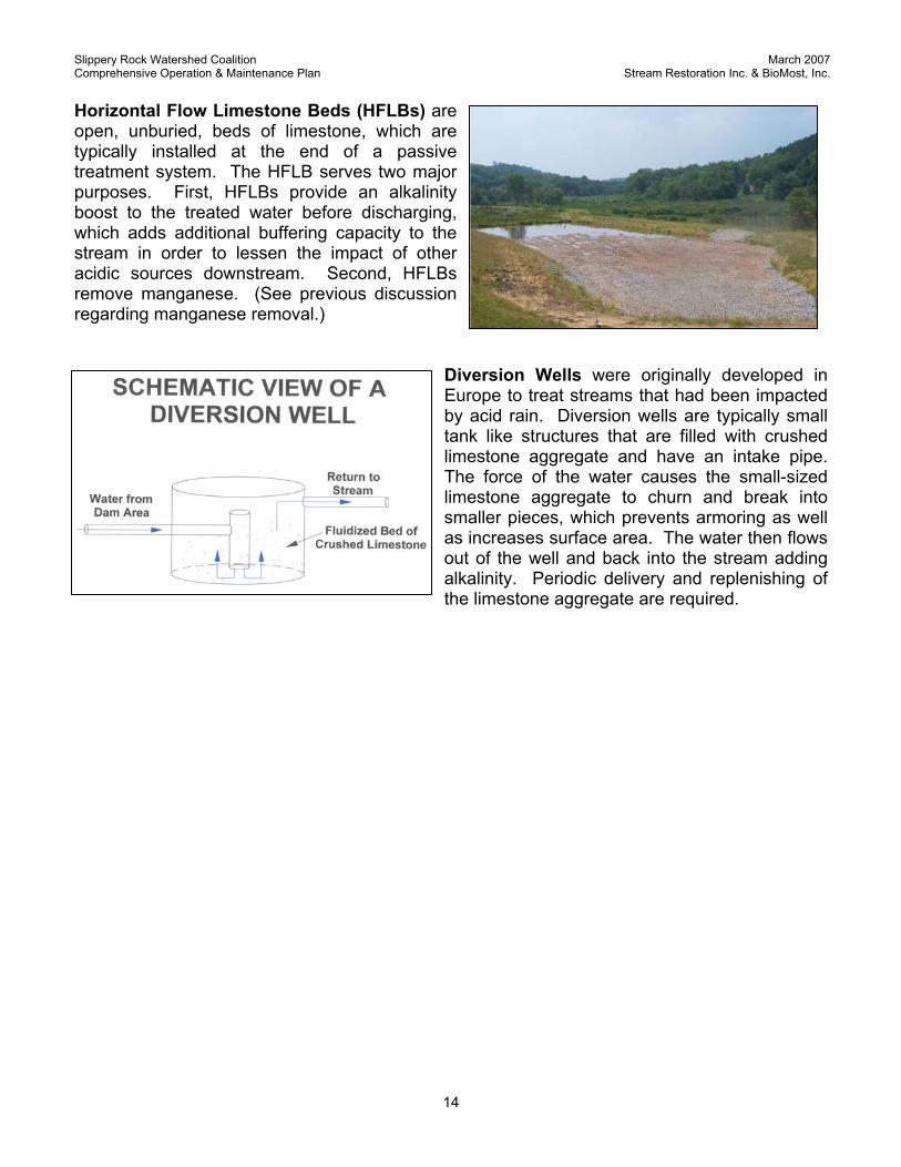
flushing capabilities. Manual flushing which is performed by opening a valve to remove, by gravity, accumulated solids from the piping and from the aggregate near the perforations, is part of the periodic maintenance needed for the component (frequency dependent on design and drainage characteristics; commonly semi-annually). Backflushing with an air compressor may also be performed on an as-needed basis. Automatic flushing uses siphons or other devices to automatically flush the treatment medium. The same settling pond used during normal operation or a separate flush pond may be used for retention of particulates dislodged during flushing. Solids are removed, as feasible, to help prevent a substantial loss in permeability of the treatment medium, in other words, to help decrease plugging. VFPs, containing mostly organic material (Spent mushroom compost is a common constituent.) utilize microbial sulfate reduction to generate alkalinity and hydrogen sulfide gas as well as to decrease sulfate concentrations. The hydrogen sulfide gas can then react with metals to form metal sulfides. Decreasing sulfates may be important to help prevent the formation of gypsum within components which can also cause plugging of treatment media and scale in pipes. Based on experience at the Jennings Environmental Education Center, a VFP containing a mixture of compost and limestone, may require “stirring” ~7 years after installation by a backhoe or other equipment to “break up” the material and restore permeability. Settling Ponds (SPs) are typically used in passive treatment systems to allow for the oxidation, precipitation, and accumulation of metal solids that occur when alkaline drainage issues from a mine or after acidic drainage has passed through an alkalinity-generating treatment component such as an ALD or VFP. Often settling ponds contain baffle curtains to reduce short-circuiting and maximize retention time. Flush Ponds (FPs) are similar to Settling Ponds. As noted, some SPs are also used as Flush Ponds. Flush Ponds receive and retain solids during flushing events of VFPs.
Wetlands (WLs), in addition to accumulating metal solids similar to Settling Ponds, can also provide a final polishing by “filtering out” particulates suspended in the water before discharging to a stream. Although many treatment wetlands are angular-shaped, shallow ponds supporting predominantly cattails, wetlands can be designed, built, and planted to look and function as a natural wetland with high species diversity to provide not only treatment but also exceptional wildlife habitat. For instance, the final wetland at the Goff Station passive system supports fish.
Bioswales combine functions of wetlands and channels. Bioswales are vegetated channels can convey flow from one component to the next as well as provide water treatment.
Slippery Rock Watershed Coalition March 2007 Comprehensive Operation & Maintenance Plan Stream Restoration Inc. & BioMost, Inc.
14
Horizontal Flow Limestone Beds (HFLBs) are open, unburied, beds of limestone, which are typically installed at the end of a passive treatment system. The HFLB serves two major purposes. First, HFLBs provide an alkalinity boost to the treated water before discharging, which adds additional buffering capacity to the stream in order to lessen the impact of other acidic sources downstream. Second, HFLBs remove manganese. (See previous discussion regarding manganese removal.)
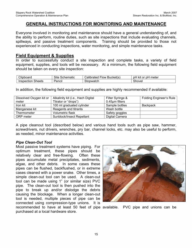
Diversion Wells were originally developed in Europe to treat streams that had been impacted by acid rain. Diversion wells are typically small tank like structures that are filled with crushed limestone aggregate and have an intake pipe. The force of the water causes the small-sized limestone aggregate to churn and break into smaller pieces, which prevents armoring as well as increases surface area. The water then flows out of the well and back into the stream adding alkalinity. Periodic delivery and replenishing of the limestone aggregate are required.
Slippery Rock Watershed Coalition March 2007 Comprehensive Operation & Maintenance Plan Stream Restoration Inc. & BioMost, Inc.
15
GENERAL INSTRUCTIONS FOR MONITORING AND MAINTENANCE
Everyone involved in monitoring and maintenance should have a general understanding of, and the ability to perform, routine duties, such as site inspections that include evaluating channels, spillways, and passive treatment components. Training should be provided to those not experienced in conducting inspections, water monitoring, and simple maintenance tasks.
Field Equipment & Supplies In order to successfully conduct a site inspection and complete tasks, a variety of field equipment, supplies, and tools will be necessary. At a minimum, the following field equipment should be taken on every site inspection:
Clipboard Site Schematic Calibrated Flow Bucket(s) pH kit or pH meter Inspection Sheets Pencil Stopwatch Shovel
In addition, the following field equipment and supplies are highly recommended if available: Dissolved Oxygen kit or meter
Alkalinity kit (i.e., Hach Digital Titrator or “drops”)
Filter Syringe & 0.45µm filters
Folding Engineer’s Rule
Iron kit 100 ml graduated cylinder Sample bottles Backpack Manganese kit Reagents and titrants Wash bottle Thermometer Volumetric flask Safety goggles ORP meter Sunblock/Insect Repellant Digital Camera A pipe cleanout tool (described below) and various hand tools such as pipe saw, hammer, screwdrivers, nut drivers, wrenches, pry bar, channel locks, etc. may also be useful to perform, as needed, minor maintenance activities. Pipe Clean-Out Tool Most passive treatment systems have piping. For optimum treatment, these pipes should be relatively clear and free-flowing. Often these pipes accumulate metal precipitates, sediments, algae, and other debris. In some cases these pipes can be flushed, backflushed, or in extreme cases cleaned with a power snake. Other times, a simple clean-out tool can be used. A clean-out tool can be made using 1” (or similar size) PVC pipe. The clean-out tool is then pushed into the pipe to break up and/or dislodge the debris causing the blockage. When a longer clean-out tool is needed, multiple pieces of pipe can be connected using compression-type unions. It is recommended to have at least 50 feet of pipe available. PVC pipe and unions can be purchased at a local hardware store.
Slippery Rock Watershed Coalition March 2007 Comprehensive Operation & Maintenance Plan Stream Restoration Inc. & BioMost, Inc.
16
Calibrated Bucket for Flow Measurements Flow measurements are very important in both designing and monitoring passive treatment systems. Passive treatment systems are generally designed based on flow rates and concentrations of pollutants. As mentioned above, passive treatment systems often have pipes. Flows from pipes can be easily measured with the “bucket-and-stopwatch” method. A bucket of known volume, preferably with gradations, is used. A 1-gallon bucket with gradations can often be found in hardware stores in the painting supply section. Although very useful, a 1-gallon bucket will not be sufficient to accurately measure larger flows. It is recommended that several calibrated flow buckets be available to the inspector, such as 1-, 5-, and 15- or 20-gallon bucket. In some cases, however, even the large buckets will not be able to measure the flow accurately. Any bucket can be calibrated by following the directions below.
Calibrating a Bucket for Flow Measurements 1. You will need :
• the bucket to be calibrated • a container of known volume (preferably 1-gallon; like an empty milk jug), and • a permanent marker.
2. Using the container of known volume, carefully (to eliminate splash) fill the bucket to be calibrated with 1 gallon of water.
3. Let the water settle and then mark the water level with a line on the inside and outside (if possible) of the bucket and write “1” for 1 gallon next to it.
4. Repeat steps 2 & 3 for each additional gallon that the bucket can hold. For a 5-gallon bucket, gradations should be labeled for each gallon. For larger buckets like a 20-gallon bucket it may be too difficult to do 1-gallon gradations. A different gradation scheme may be desired such as marks at 5, 10, and 15 gallons. Other variations are possible and acceptable as long as relatively accurate measurements can be made.
Passive Treatment System O&M Inspection Report In order to maintain the integrity of a passive treatment facility, the site should be inspected at regular intervals and after major precipitation events or other natural/manmade occurrences that may affect the performance or integrity of the structure. Regular site inspections should be conducted at the frequency indicated (typically quarterly, semi-annually, or annually) on the inspection schedule table. A qualified person should perform the inspection and complete the appropriate report(s). (See attached inspection report forms.) The inspector should keep the paper copy of the report in permanent files in chronological order. These reports can also be filed at the office of Stream Restoration Incorporated. In addition, prior to filing the reports the data and other pertinent information should be entered into the online, GIS-enabled, database via the website www.datashed.org. Passwords to the site as well as instructions and training can be obtained by contacting Stream Restoration Incorporated. (See the Datashed section.) The report should include the inspection date, the inspector’s name, the organization with which the inspector is affiliated, and the start and end time of the actual inspection. The following sections correspond in general with the attached individual Passive Treatment System and Land Reclamation O&M Inspection Reports.
Slippery Rock Watershed Coalition March 2007 Comprehensive Operation & Maintenance Plan Stream Restoration Inc. & BioMost, Inc.
17
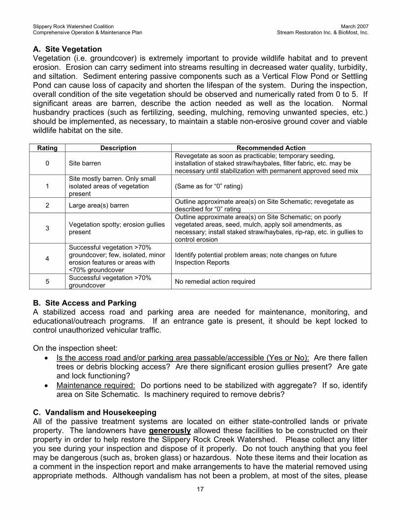
A. Site Vegetation Vegetation (i.e. groundcover) is extremely important to provide wildlife habitat and to prevent erosion. Erosion can carry sediment into streams resulting in decreased water quality, turbidity, and siltation. Sediment entering passive components such as a Vertical Flow Pond or Settling Pond can cause loss of capacity and shorten the lifespan of the system. During the inspection, overall condition of the site vegetation should be observed and numerically rated from 0 to 5. If significant areas are barren, describe the action needed as well as the location. Normal husbandry practices (such as fertilizing, seeding, mulching, removing unwanted species, etc.) should be implemented, as necessary, to maintain a stable non-erosive ground cover and viable wildlife habitat on the site.
Rating Description Recommended Action
0 Site barren Revegetate as soon as practicable; temporary seeding, installation of staked straw/haybales, filter fabric, etc. may be necessary until stabilization with permanent approved seed mix
1 Site mostly barren. Only small isolated areas of vegetation present
(Same as for “0” rating)
2 Large area(s) barren Outline approximate area(s) on Site Schematic; revegetate as described for “0” rating
3 Vegetation spotty; erosion gullies present
Outline approximate area(s) on Site Schematic; on poorly vegetated areas, seed, mulch, apply soil amendments, as necessary; install staked straw/haybales, rip-rap, etc. in gullies to control erosion
4
Successful vegetation >70% groundcover; few, isolated, minor erosion features or areas with <70% groundcover
Identify potential problem areas; note changes on future Inspection Reports
5 Successful vegetation >70% groundcover No remedial action required
B. Site Access and Parking A stabilized access road and parking area are needed for maintenance, monitoring, and educational/outreach programs. If an entrance gate is present, it should be kept locked to control unauthorized vehicular traffic. On the inspection sheet:
• Is the access road and/or parking area passable/accessible (Yes or No): Are there fallen trees or debris blocking access? Are there significant erosion gullies present? Are gate and lock functioning?
• Maintenance required: Do portions need to be stabilized with aggregate? If so, identify area on Site Schematic. Is machinery required to remove debris?
C. Vandalism and Housekeeping All of the passive treatment systems are located on either state-controlled lands or private property. The landowners have generously allowed these facilities to be constructed on their property in order to help restore the Slippery Rock Creek Watershed. Please collect any litter you see during your inspection and dispose of it properly. Do not touch anything that you feel may be dangerous (such as, broken glass) or hazardous. Note these items and their location as a comment in the inspection report and make arrangements to have the material removed using appropriate methods. Although vandalism has not been a problem, at most of the sites, please
Slippery Rock Watershed Coalition March 2007 Comprehensive Operation & Maintenance Plan Stream Restoration Inc. & BioMost, Inc.
18
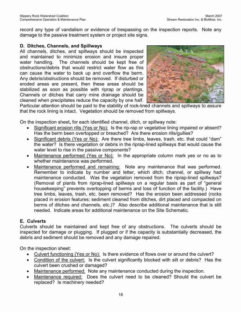
record any type of vandalism or evidence of trespassing on the inspection reports. Note any damage to the passive treatment system or project site signs. D. Ditches, Channels, and Spillways All channels, ditches, and spillways should be inspected and maintained to minimize erosion and insure proper water handling. The channels should be kept free of obstructions/debris that would restrict water flow as this can cause the water to back up and overflow the berm. Any debris/obstructions should be removed. If disturbed or eroded areas are present, then these areas should be stabilized as soon as possible with riprap or plantings. Channels or ditches that carry mine drainage should be cleaned when precipitates reduce the capacity by one half. Particular attention should be paid to the stability of rock-lined channels and spillways to assure that the rock lining is intact. Vegetation should be removed from spillways. On the inspection sheet, for each identified channel, ditch, or spillway note:
• Significant erosion rills (Yes or No): Is the rip-rap or vegetative lining impaired or absent? Has the berm been overtopped or breached? Are there erosion rills/gullies?
• Significant debris (Yes or No): Are there tree limbs, leaves, trash, etc. that could “dam” the water? Is there vegetation or debris in the riprap-lined spillways that would cause the water level to rise in the passive components?
• Maintenance performed (Yes or No): In the appropriate column mark yes or no as to whether maintenance was performed.
• Maintenance performed and remaining: Note any maintenance that was performed. Remember to indicate by number and letter, which ditch, channel, or spillway had maintenance conducted. Was the vegetation removed from the riprap-lined spillways? (Removal of plants from riprap-lined spillways on a regular basis as part of “general housekeeping” prevents overtopping of berms and loss of function of the facility.) Have tree limbs, leaves, trash, etc. been removed? Has the erosion been addressed (rocks placed in erosion features; sediment cleaned from ditches, dirt placed and compacted on berms of ditches and channels, etc.)? Also describe additional maintenance that is still needed. Indicate areas for additional maintenance on the Site Schematic.
E. Culverts Culverts should be maintained and kept free of any obstructions. The culverts should be inspected for damage or plugging. If plugged or if the capacity is substantially decreased, the debris and sediment should be removed and any damage repaired. On the inspection sheet:
• Culvert functioning (Yes or No): Is there evidence of flows over or around the culvert? • Condition of the culvert: Is the culvert significantly blocked with silt or debris? Has the
culvert been crushed or damaged? • Maintenance performed: Note any maintenance conducted during the inspection. • Maintenance required: Does the culvert need to be cleaned? Should the culvert be
replaced? Is machinery needed?
Slippery Rock Watershed Coalition March 2007 Comprehensive Operation & Maintenance Plan Stream Restoration Inc. & BioMost, Inc.
19
F. Passive Treatment System Components All passive treatment components such as Vertical Flow Ponds, Settling Ponds, wetlands, and collection systems that intercept, convey, and/or treat water need to be inspected for erosion, berm (slope) stability, vegetation, siltation, leaks, etc. Any problem should be noted and corrected as soon as practicable. Water inlets and outlets for all structures should be observed during each site inspection and kept free from sediment, leaves, and other foreign objects. This is very important for the efficient operation of the system. Any debris present in the water inlet/outlet areas should be removed. All flow control structures should be maintained to be free-flowing. Plugged and partially plugged pipes need to be cleaned. Broken pipes need to be replaced. All valves should be monitored and maintained so the free-flow of water continues during normal operation. Valves also need to be monitored to insure full operation (are able to be completely opened & closed) and that no leakage is occurring. Broken valves will need to be replaced. The condition of the vegetation and the presence of any disturbed or eroded areas should be noted. Disturbed or eroded areas will need to be stabilized as soon as possible with staked straw/haybales, riprap, plantings with accepted species, etc., whichever is appropriate. Any signs of water overtopping or leaking through the berms should be noted and investigations conducted to determine the cause as soon as possible. On the inspection sheet, for each identified passive treatment component note:
• Significant erosion (Yes or No): Do berms (inside & outside) have erosion gullies? • Are the berms stable (Yes or No): Is there any slumping? Are there cracks? • Successful vegetation (Yes or No): Are there significant areas on the berms (inside &
outside) that need to be revegetated? Overall, does the vegetation appear healthy? • Significant siltation/sedimentation (Yes or No): Is there significant sediment from erosion
of berms or upland areas accumulating in the passive component? • Significant change in water level (Yes or No): Is the water level rising or lowering in the
passive component? Is there water discharging from the emergency spillway or over the berm? Is the water level appropriate (not too high or too low) for the plants in the wetlands? Has a pond been drained that should not be?
• Valves operable (Yes or No): Are all valves able to be opened and closed by hand? Are the valves in good condition? (All valves should be opened and closed during each inspection in order to maintain proper function.)
• Maintenance performed and remaining: Describe any maintenance conducted or needed. Remember to identify the component. Do portions of the berms need to be stabilized with riprap and/or reconstructed? Does supplemental reseeding and mulching need to be completed? Do passive components or pipes need to be cleaned of sediment? Do valves need to be replaced? Are any pipes broken or plugged?
G. Wildlife Utilization One of the functions of a constructed wetland is to provide wildlife habitat for desired species. If, however, during inspections, signs of damage are noted, such as from muskrats in wetlands, appropriate steps should be taken to continue the function of the passive system and general
Slippery Rock Watershed Coalition March 2007 Comprehensive Operation & Maintenance Plan Stream Restoration Inc. & BioMost, Inc.
20
site restoration. Significant damage needs to be corrected by repairing berms, removing invasive species, replanting, and trapping (contact PA Game Commission). On the inspection sheet:
• Animals observed: Although not an inventory, please record whether there were tracks or visual observations of wildlife utilizing the site. Describe any damage observed.
• Invasive plants observed: If invasive or undesirable plants are observed, please note and remove as soon as practicable.
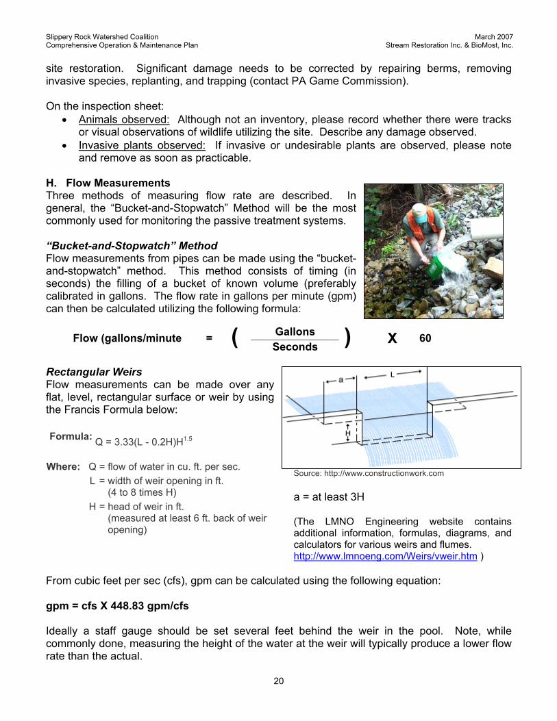
H. Flow Measurements Three methods of measuring flow rate are described. In general, the “Bucket-and-Stopwatch” Method will be the most commonly used for monitoring the passive treatment systems. “Bucket-and-Stopwatch” Method Flow measurements from pipes can be made using the “bucket-and-stopwatch” method. This method consists of timing (in seconds) the filling of a bucket of known volume (preferably calibrated in gallons. The flow rate in gallons per minute (gpm) can then be calculated utilizing the following formula:
Rectangular Weirs Flow measurements can be made over any flat, level, rectangular surface or weir by using the Francis Formula below: Formula:
Q = 3.33(L - 0.2H)H1.5
Source: http://www.constructionwork.com a = at least 3H (The LMNO Engineering website contains additional information, formulas, diagrams, and calculators for various weirs and flumes. http://www.lmnoeng.com/Weirs/vweir.htm )
From cubic feet per sec (cfs), gpm can be calculated using the following equation: gpm = cfs X 448.83 gpm/cfs Ideally a staff gauge should be set several feet behind the weir in the pool. Note, while commonly done, measuring the height of the water at the weir will typically produce a lower flow rate than the actual.
Gallons Flow (gallons/minute = ( Seconds ) X 60
Q = flow of water in cu. ft. per sec. L = width of weir opening in ft.
(4 to 8 times H) H = head of weir in ft.
(measured at least 6 ft. back of weir opening)
Where:
Slippery Rock Watershed Coalition March 2007 Comprehensive Operation & Maintenance Plan Stream Restoration Inc. & BioMost, Inc.
21
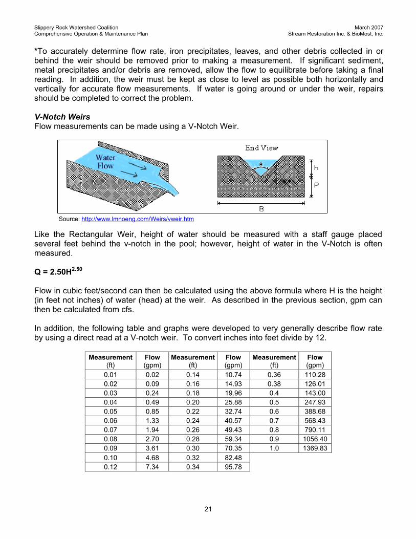
*To accurately determine flow rate, iron precipitates, leaves, and other debris collected in or behind the weir should be removed prior to making a measurement. If significant sediment, metal precipitates and/or debris are removed, allow the flow to equilibrate before taking a final reading. In addition, the weir must be kept as close to level as possible both horizontally and vertically for accurate flow measurements. If water is going around or under the weir, repairs should be completed to correct the problem. V-Notch Weirs Flow measurements can be made using a V-Notch Weir.
Source: http://www.lmnoeng.com/Weirs/vweir.htm
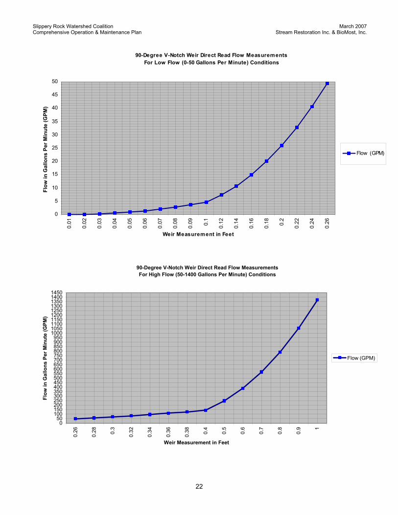
Like the Rectangular Weir, height of water should be measured with a staff gauge placed several feet behind the v-notch in the pool; however, height of water in the V-Notch is often measured. Q = 2.50H2.50 Flow in cubic feet/second can then be calculated using the above formula where H is the height (in feet not inches) of water (head) at the weir. As described in the previous section, gpm can then be calculated from cfs. In addition, the following table and graphs were developed to very generally describe flow rate by using a direct read at a V-notch weir. To convert inches into feet divide by 12.
Measurement (ft)
Flow (gpm)
Measurement (ft)
Flow (gpm)
Measurement (ft)
Flow (gpm)
0.01 0.02 0.14 10.74 0.36 110.28 0.02 0.09 0.16 14.93 0.38 126.01 0.03 0.24 0.18 19.96 0.4 143.00 0.04 0.49 0.20 25.88 0.5 247.93 0.05 0.85 0.22 32.74 0.6 388.68 0.06 1.33 0.24 40.57 0.7 568.43 0.07 1.94 0.26 49.43 0.8 790.11 0.08 2.70 0.28 59.34 0.9 1056.40 0.09 3.61 0.30 70.35 1.0 1369.83 0.10 4.68 0.32 82.48 0.12 7.34 0.34 95.78
Slippery Rock Watershed Coalition March 2007 Comprehensive Operation & Maintenance Plan Stream Restoration Inc. & BioMost, Inc.
22
90-Degree V-Notch Weir Direct Read Flow Measurements For Low Flow (0-50 Gallons Per Minute) Conditions
0
5
10
15
20
25
30
35
40
45
50
0.01
0.02
0.03
0.04
0.05
0.06
0.07
0.08
0.09 0.1
0.12
0.14
0.16
0.18 0.2
0.22
0.24
0.26
Weir Measurement in Feet
Flow
in G
allo
ns P
er M
inut
e (G
PM)
Flow (GPM)
90-Degree V-Notch Weir Direct Read Flow Measurements For High Flow (50-1400 Gallons Per Minute) Conditions
050
100150200250300350400450500550600650700750800850900950
1000105011001150120012501300135014001450
0.26
0.28 0.3
0.32
0.34
0.36
0.38 0.4
0.5
0.6
0.7
0.8
0.9 1
Weir Measurement in Feet
Flow
in G
allo
ns P
er M
inut
e (G
PM)
Flow (GPM)
Slippery Rock Watershed Coalition March 2007 Comprehensive Operation & Maintenance Plan Stream Restoration Inc. & BioMost, Inc.
23
I. Field Water Monitoring and Sample Collection In order to assess the efficiency and performance of a passive system, water monitoring of each component of the system should be completed according to the attached schedule. Water monitoring is perhaps the most important element of the O&M site inspection as it directly indicates whether the system is functioning properly and can help to identify problems that cannot be directly seen. If possible, water samples should be taken and analyzed by the PA State Lab or other approved laboratory using standard chemical testing procedures for the following water quality parameters.
Laboratory Water Quality Parameters
pH Total Iron Total Aluminum Alkalinity Dissolved Iron Dissolved Aluminum Acidity Total Manganese Sulfates Specific Conductance Dissolved Manganese Total Suspended Solids
Total calcium would also be valuable. In addition to laboratory analyses, field tests should be completed including flow (as feasible), pH, temperature, and alkalinity. ORP measurements can also be a valuable indicator of system function. If water samples cannot be taken for laboratory analysis then, at a minimum, the following field tests should be completed: pH, temperature, alkalinity, and dissolved iron. Alkalinity is not completed when pH ≤ 4.5. Water sampling and field testing should be completed at locations identified on the O&M Inspection Sheet and Site Schematic. Water monitoring will enable evaluation of the degree of success of the passive components, individually and combined, in treating the mine drainage. The monitoring program should include points other than the final effluent in order to provide a complete depiction of the water quality through the passive treatment system at the time of sampling. For instance, the untreated raw mine discharge (as close to the source as possible), each component (at the effluent), and the stream (above and below the system) should be monitored. These monitoring points are identified on the O&M Inspection Sheet, site schematic, and “As-Built” plans. Monitoring of individual components is important to identify problems particular to the component that may not be noticed in the final effluent of the entire system. In order to conduct laboratory analyses for pH, alkalinity, acidity, sulfates, conductivity, and total suspended solids, a 500-ml (or other volume specified by the laboratory), unfiltered, sample should be collected, stored in a cooler, and transported to the laboratory. In order to differentiate between dissolved and total iron, manganese, and aluminum concentrations, the laboratory requires two, 125-ml (or other specified volume) samples that are preserved with trace metal-grade nitric acid to ensure that the pH is <2. The sample for total metals is not filtered. The sample for dissolved metals is filtered in the field using a 0.45-µm filter during sampling. At a minimum the filtering device should be rinsed three times with the water to be sampled. Each bottle should be labeled with a unique number. For a single component that contains multiple discharge points (e.g. multiple effluent pipes from the same Vertical Flow Pond) a composite sample may be taken. This can be accomplished in several ways. One method would be to use a clean bottle or bucket and to capture a proportionate amount of sample from each discharge point and allow the waters to mix. This can be accomplished by timing or counting such that the water is collected for the same amount of time at each location, which will effectively proportionate the sample. If the multiple flows mix

Slippery Rock Watershed Coalition March 2007 Comprehensive Operation & Maintenance Plan Stream Restoration Inc. & BioMost, Inc.
24
together in a spillway, the sample may be collected at the end of the spillway. Importantly, the various sources must be well mixed or the results could be skewed. A record of every sample taken should be made directly on the inspection sheet, such as sampler’s name, sample location, sample date, flow rate, field tests, and sample bottle identification. Pertinent information is then transferred from the inspection sheets to the laboratory’s Record of Sample form or Chain of Custody form. On the inspection sheet for each Sampling Point:
• Monitoring point field measurements recorded: Record readings to nearest whole number, except pH (record to nearest tenth).
Parameter Method Flow Bucket & Stopwatch (where pipe discharge), weir, etc. pH HACH pH kit, pH meter, etc. Temperature Field thermometer, pH meter, etc. ORP (optional) ORP meter Total Alkalinity HACH Digital Titrator, etc. Iron HACH iron, etc. Dissolved oxygen (optional) HACH DO kit, DO meter, etc.
• Sample bottle data: If water samples are collected, assign and record bottle numbers on
the inspection sheet. You will need to transfer this information to the laboratory’s Record of Sample or Chain of Custody form.
• Comments: Observations such as sample color may be recorded under “Comments”. Sludge Accumulation Assessment Report In addition to the periodic O&M Inspection Reports, it is recommended that a Sludge Accumulation Inspection Report be completed every couple years. The primary purpose of this inspection is to assess the type and amount of sludge accumulating within the passive treatment components. This can give an indication as to how the system is functioning and when action is needed to remove the sludge from the component. A proposed schedule and a general Sludge Accumulation Assessment Report has been included that can be used for all sites. On the Sludge Accumulation Assessment Report, for each component provide:
• Sludge description: Note the color and depth (estimated) of the sludge. Typically, white, red, and black colors indicate precipitate rich in aluminum, iron, and black, respectively. Has the sludge filled the component to within 1 foot of the emergency spillway?
• Comments: For example: Is there significant organic debris in the sludge? Is there evidence of wildlife utilizing the component? Estimated depth of sludge?
Wetland Plant Diversity Report Although not necessary to complete, a general Wetland Plant Diversity Report has been provided. The primary purpose of this report is to assess the diversity of plant species within a constructed treatment wetland in order to determine if species diversity is increasing or decreasing. Species diversity is believed to increase the health, productivity, and treatment capability of the wetland. In addition, increased plant species diversity should result in an increase in wildlife diversity. A secondary purpose is to identify if unwanted invasive plants have become established. These plants should be removed from the wetlands. On the report provide
Slippery Rock Watershed Coalition March 2007 Comprehensive Operation & Maintenance Plan Stream Restoration Inc. & BioMost, Inc.
25
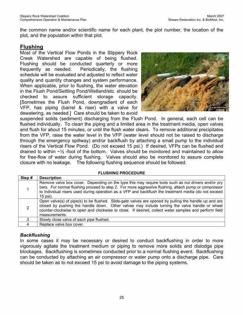
the common name and/or scientific name for each plant, the plot number, the location of the plot, and the population within that plot. Flushing Most of the Vertical Flow Ponds in the Slippery Rock Creek Watershed are capable of being flushed. Flushing should be conducted quarterly or more frequently as needed. Periodically, the flushing schedule will be evaluated and adjusted to reflect water quality and quantity changes and system performance. When applicable, prior to flushing, the water elevation in the Flush Pond/Settling Pond/Wetland/etc. should be checked to assure sufficient storage capacity. [Sometimes the Flush Pond, downgradient of each VFP, has piping (barrel & riser) with a valve for dewatering, as needed.] Care should be taken to avoid suspended solids (sediment) discharging from the Flush Pond. In general, each cell can be flushed individually. To clean the piping and a limited area in the treatment media, open valves and flush for about 15 minutes, or until the flush water clears. To remove additional precipitates from the VFP, raise the water level in the VFP (water level should not be raised to discharge through the emergency spillway) and/or backflush by attaching a small pump to the individual risers of the Vertical Flow Pond. (Do not exceed 15 psi.) If desired, VFPs can be flushed and drained to within ~½ -foot of the bottom. Valves should be monitored and maintained to allow for free-flow of water during flushing. Valves should also be monitored to assure complete closure with no leakage. The following flushing sequence should be followed.
FLUSHING PROCEDURE Step # Description
1
Remove valve box cover. Depending on the type this may require tools such as nut drivers and/or pry bars. For normal flushing proceed to step 2. For more aggressive flushing, attach pump or compressor to individual risers used during operation as a VFP and backflush the treatment media (do not exceed 15 psi).
2
Open valve(s) of pipe(s) to be flushed. Slide-gate valves are opened by pulling the handle up and are closed by pushing the handle down. Other valves may include turning the valve handle or wheel counter-clockwise to open and clockwise to close. If desired, collect water samples and perform field measurements.
3 Slowly close valve of each pipe flushed. 4 Replace valve box cover.
Backflushing In some cases it may be necessary or desired to conduct backflushing in order to more vigorously agitate the treatment medium or piping to remove more solids and dislodge pipe blockages. Backflushing is sometimes conducted prior to a normal flushing event. Backflushing can be conducted by attaching an air compressor or water pump onto a discharge pipe. Care should be taken as to not exceed 15 psi to avoid damage to the piping systems.
Slippery Rock Watershed Coalition March 2007 Comprehensive Operation & Maintenance Plan Stream Restoration Inc. & BioMost, Inc.
26
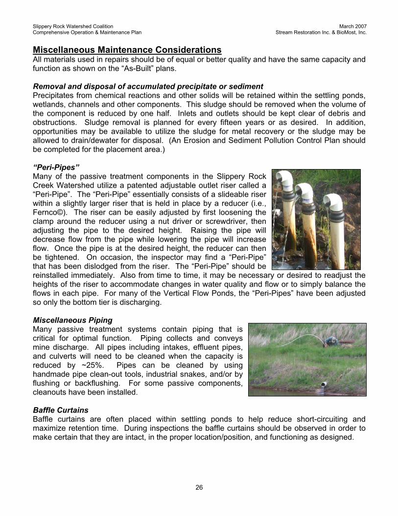
Miscellaneous Maintenance Considerations All materials used in repairs should be of equal or better quality and have the same capacity and function as shown on the “As-Built” plans. Removal and disposal of accumulated precipitate or sediment Precipitates from chemical reactions and other solids will be retained within the settling ponds, wetlands, channels and other components. This sludge should be removed when the volume of the component is reduced by one half. Inlets and outlets should be kept clear of debris and obstructions. Sludge removal is planned for every fifteen years or as desired. In addition, opportunities may be available to utilize the sludge for metal recovery or the sludge may be allowed to drain/dewater for disposal. (An Erosion and Sediment Pollution Control Plan should be completed for the placement area.) “Peri-Pipes” Many of the passive treatment components in the Slippery Rock Creek Watershed utilize a patented adjustable outlet riser called a “Peri-Pipe”. The “Peri-Pipe” essentially consists of a slideable riser within a slightly larger riser that is held in place by a reducer (i.e., Fernco©). The riser can be easily adjusted by first loosening the clamp around the reducer using a nut driver or screwdriver, then adjusting the pipe to the desired height. Raising the pipe will decrease flow from the pipe while lowering the pipe will increase flow. Once the pipe is at the desired height, the reducer can then be tightened. On occasion, the inspector may find a “Peri-Pipe” that has been dislodged from the riser. The “Peri-Pipe” should be reinstalled immediately. Also from time to time, it may be necessary or desired to readjust the heights of the riser to accommodate changes in water quality and flow or to simply balance the flows in each pipe. For many of the Vertical Flow Ponds, the “Peri-Pipes” have been adjusted so only the bottom tier is discharging. Miscellaneous Piping Many passive treatment systems contain piping that is critical for optimal function. Piping collects and conveys mine discharge. All pipes including intakes, effluent pipes, and culverts will need to be cleaned when the capacity is reduced by ~25%. Pipes can be cleaned by using handmade pipe clean-out tools, industrial snakes, and/or by flushing or backflushing. For some passive components, cleanouts have been installed. Baffle Curtains Baffle curtains are often placed within settling ponds to help reduce short-circuiting and maximize retention time. During inspections the baffle curtains should be observed in order to make certain that they are intact, in the proper location/position, and functioning as designed.
Slippery Rock Watershed Coalition March 2007 Comprehensive Operation & Maintenance Plan Stream Restoration Inc. & BioMost, Inc.
27
Replacement All passive treatment systems are unique. The sludge storage capacity for passive components varies from component to component and site to site. Design capacity is based upon available water quality monitoring data and published references. Higher flow rates and poorer water quality can substantially affect the design life. When the storage capacity of the system is diminished by approximately one half, the sludge should be removed. Prior to removal, the system and water quality should be evaluated to determine if reconstruction is necessary. Advances in technology and changes in raw drainage quality and quantity should be considered to determine if revisions to the size and/or design of the system is advantageous. Replacement considerations include:
- Estimating Best Management Practice (BMP) design life; - Determining replacement responsibility, including a successor, as necessary; - Determining approximate costs for the following possible needs:
o removing accumulated sediments; o replacing defective valves, water control structures, etc.; o re-sizing the system to accommodate changed water quality or quantity; o recharging organic matter in wetlands; and o replanting wetlands.
Datashed Datashed, www.datashed.org, is a fully-featured, GIS-enabled, internet database designed to assist watershed groups, academic institutions, private industry, and government agencies. Powered by open source software, this database provides a cost-effective and reliable solution to the management of data associated with environmental efforts. GIS capability allows users to easily view geographic data and directs users to additional content. Anyone with internet access can view the site and download information. This allows the website to function not only as a data management tool but also as part of the education/outreach effort associated with the project. Datashed was developed by Stream Restoration Incorporated, 241 Computer Services, and WPCAMR using the PHP programming language and open source software such as APACHE HTTP Server, MySQL database, and Map Server. Datashed has been incorporated as an essential component of the Slippery Rock Watershed Coalition’s comprehensive O&M Plan. Each restoration project has its own page within the website where users can not only view data but also download and print information needed to conduct O&M inspections such as site inspection sheets, site schematics, topographic maps, aerial photos, etc. In addition, those who conduct the inspections will be given passwords to allow direct online upload of collected field and laboratory data from the inspection.

Slippery Rock Watershed Coalition March 2007 Comprehensive Operation & Maintenance Plan Stream Restoration Inc. & BioMost, Inc.
28
To view, download forms, or upload data onto the site use the following directions below:
Viewing, Downloading, and Uploading Data to Datashed
1. Go to Datashed (www.datashed.org). To view data or download forms go to step 2. To upload data such as completing the online O&M form, you will need to first login using your assigned email address and password. If you do not have a password, contact Stream Restoration Incorporated.
2. Select the “Projects” tab. 3. A Project Search Query should appear. This feature allows the user to search for
projects based on a variety of selections criterion. Once the criteria has been selected, click on the “List Projects” button
4. A list of available projects matching the criteria with short descriptions should appear. 5. Select the project that you wish to view, download forms, or upload data. The “Project
Details” report page will automatically open. 6. Select:
• “Maps and Directions” to get directions to the site • “Downloads” to obtain O&M forms, site schematics, location map, “as-builts”, etc • “View Data” to view O&M submissions, graphs, reports, and data • “View Pictures” for project photos • “Partners” to view a list of partners involved in the project • “Submit Data” to access and upload data via the on-line O&M form
7. Enter the data from the O&M field inspection sheet. When finished, click submit button.
Slippery Rock Watershed Coalition March 2007 Comprehensive Operation & Maintenance Plan Stream Restoration Inc. & BioMost, Inc.
29
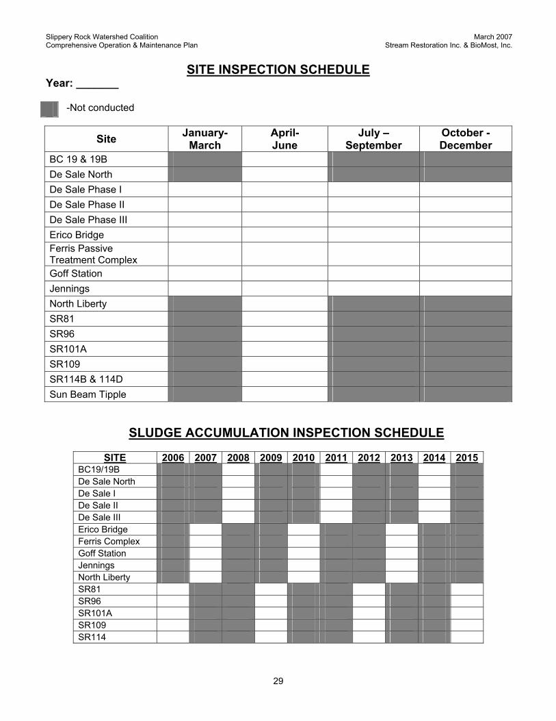
SITE INSPECTION SCHEDULE Year: _______
-Not conducted
Site January-March
April- June
July – September
October - December
BC 19 & 19B De Sale North De Sale Phase I De Sale Phase II De Sale Phase III Erico Bridge Ferris Passive Treatment Complex Goff Station Jennings North Liberty SR81 SR96 SR101A SR109 SR114B & 114D Sun Beam Tipple
SLUDGE ACCUMULATION INSPECTION SCHEDULE
SITE 2006 2007 2008 2009 2010 2011 2012 2013 2014 2015BC19/19B De Sale North De Sale I De Sale II De Sale III Erico Bridge Ferris Complex Goff Station Jennings North Liberty SR81 SR96 SR101A SR109 SR114