Embed Size (px)
Citation preview
SLIPLINING Sewer Rehabilitation Centrifugally Cast Fiberglass Reinforced Polymer Mortar Pipe
Bijan Khamaian
1/12/17
Seattle
Agenda
OIntroduction on Hobas
OSlipline Pipe Product details
OFeatures and benefits
OCase histories (Sliplining)
OQuestions & answers
Agenda
O Overview of CCFRPM Product
O Overview of Sliplining with Basic Procedure & Design Considerations
- Common Questions
– What Pipe Will Fit?
– Can I Maintain Capacity?
– How Far Can I Push?
O Summary / Q & A
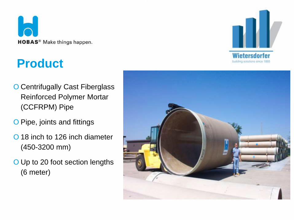
Product
O Centrifugally Cast Fiberglass
Reinforced Polymer Mortar
(CCFRPM) Pipe
O Pipe, joints and fittings
O 18 inch to 126 inch diameter
(450-3200 mm)
O Up to 20 foot section lengths
(6 meter)
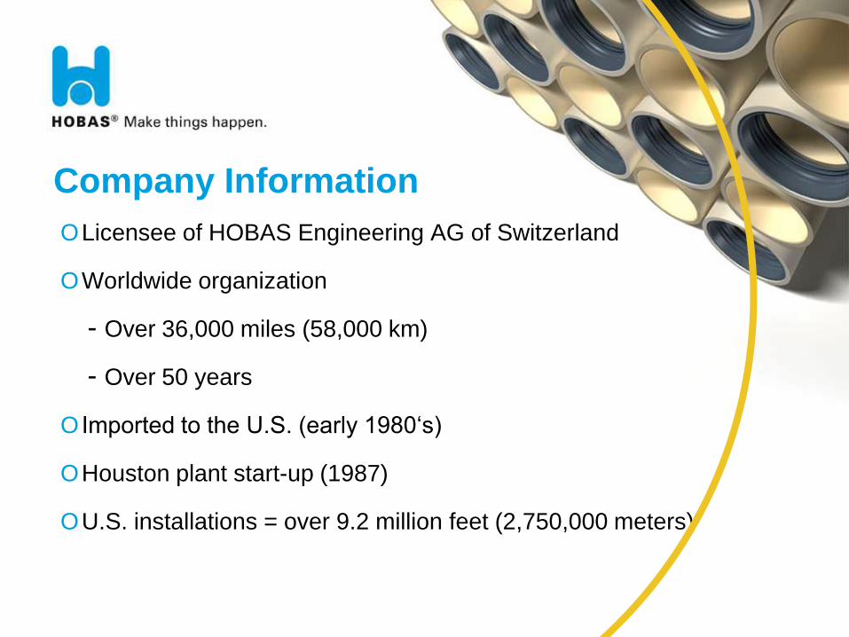
Company Information
OLicensee of HOBAS Engineering AG of Switzerland
OWorldwide organization
- Over 36,000 miles (58,000 km)
- Over 50 years
O Imported to the U.S. (early 1980‘s)
OHouston plant start-up (1987)
OU.S. installations = over 9.2 million feet (2,750,000 meters)
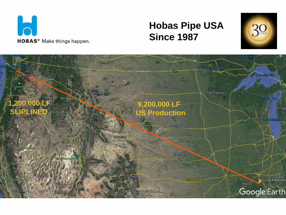
1,200,000 LF
SLIPLINED 9,200,000 LF
US Production
Hobas Pipe USA
Since 1987
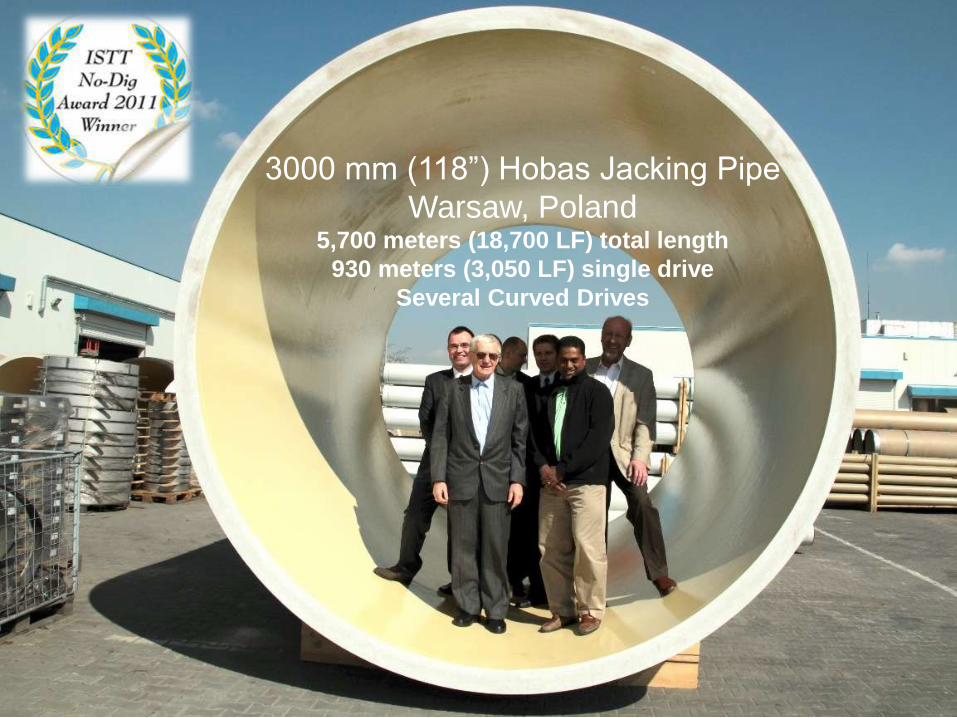
3000 mm (118”) Hobas Jacking Pipe
Warsaw, Poland 5,700 meters (18,700 LF) total length
930 meters (3,050 LF) single drive
Several Curved Drives
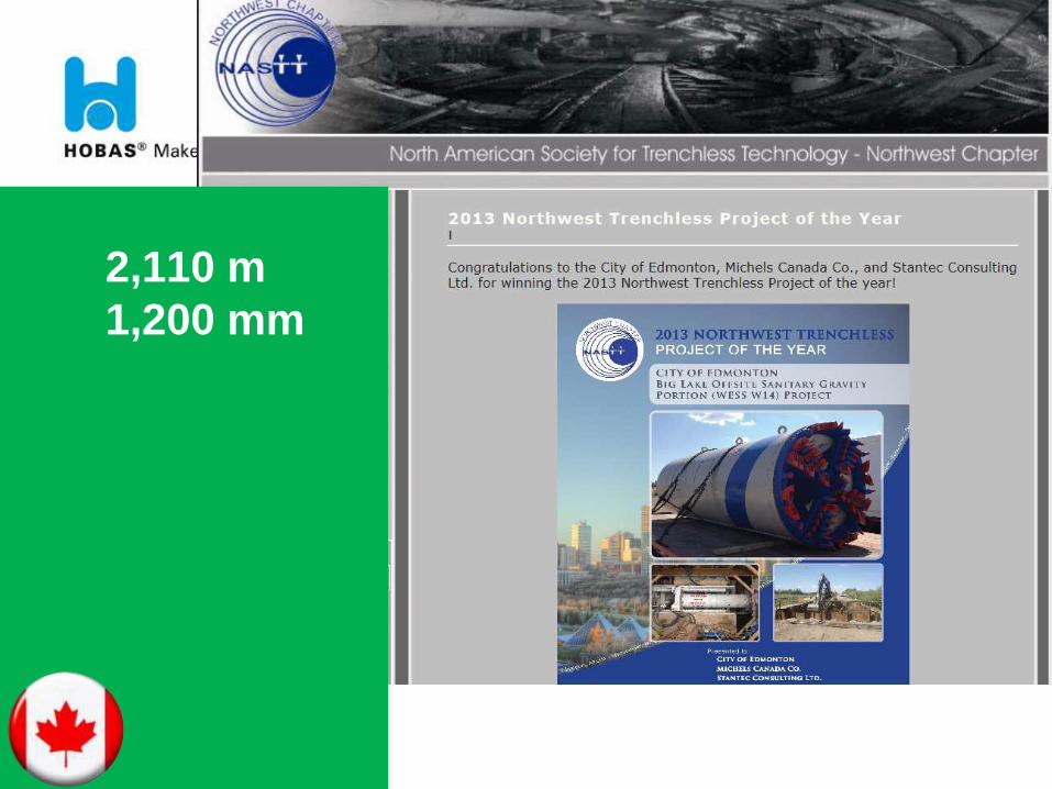
2,110 m
1,200 mm

BAP-HEA-090125-HAC IT 11
Global Organization
BAP-HEA-090125-HAC IT 12
Houston Factory
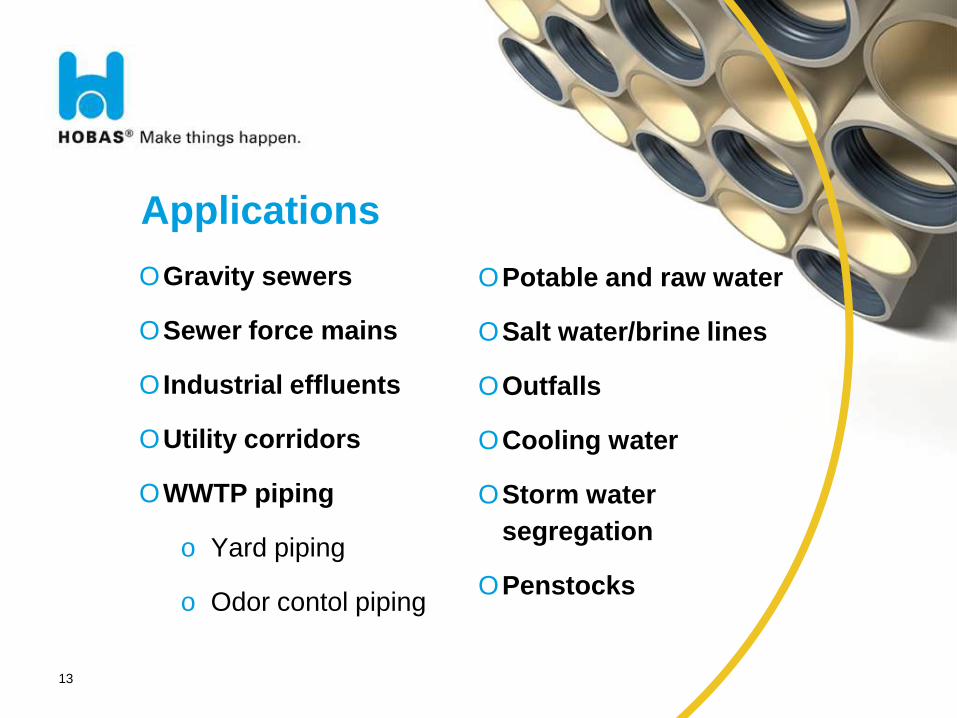
Applications
OGravity sewers
OSewer force mains
O Industrial effluents
OUtility corridors
OWWTP piping
o Yard piping
o Odor contol piping
13
OPotable and raw water
OSalt water/brine lines
OOutfalls
OCooling water
OStorm water
segregation
OPenstocks
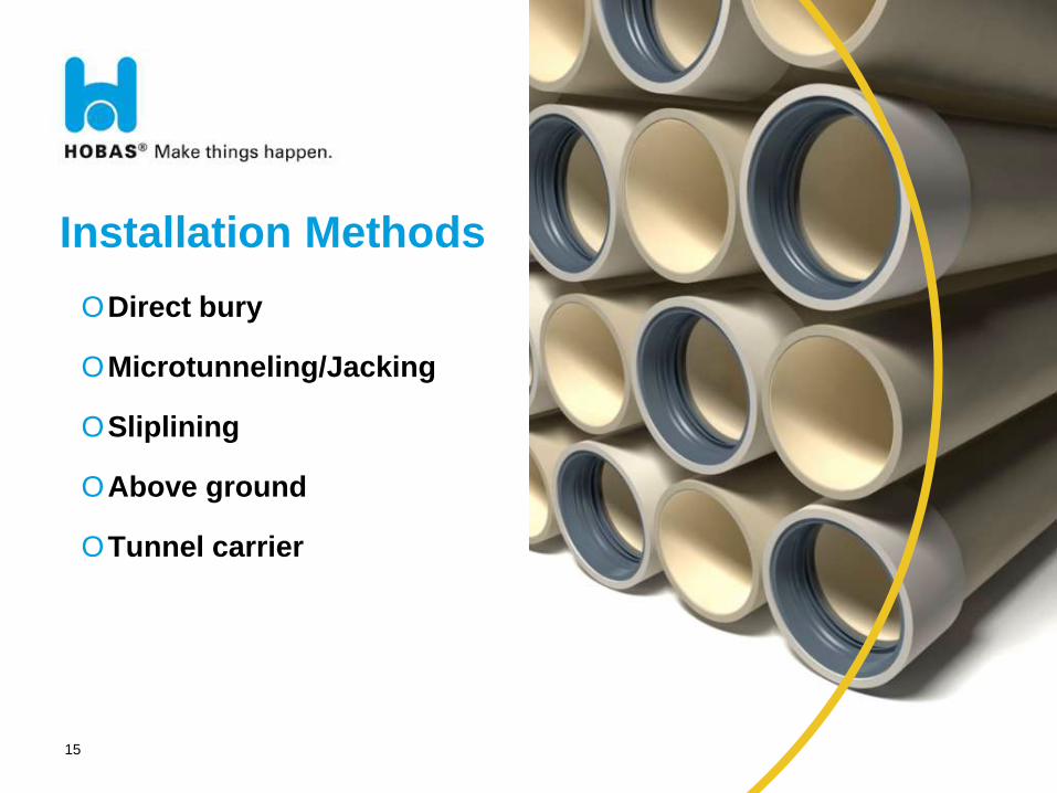
Installation Methods
15
ODirect bury
OMicrotunneling/Jacking
OSliplining
OAbove ground
OTunnel carrier
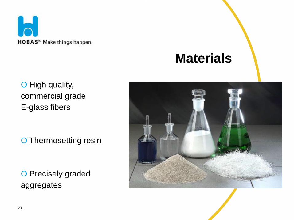
Materials
21
O High quality,
commercial grade
E-glass fibers
O Thermosetting resin
O Precisely graded
aggregates
22
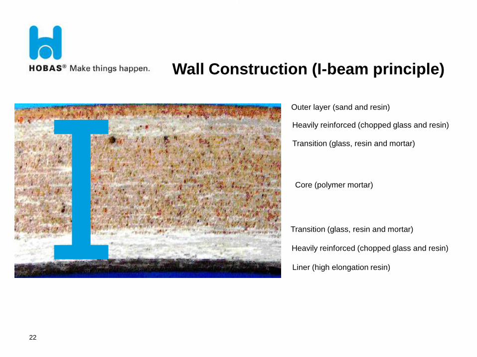
Wall Construction (I-beam principle)
Outer layer (sand and resin)
Heavily reinforced (chopped glass and resin)
Transition (glass, resin and mortar)
Core (polymer mortar)
Transition (glass, resin and mortar)
Heavily reinforced (chopped glass and resin)
Liner (high elongation resin)
25
Process
26
Process
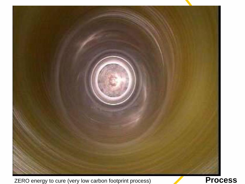
27
Process ZERO energy to cure (very low carbon footprint process)
31
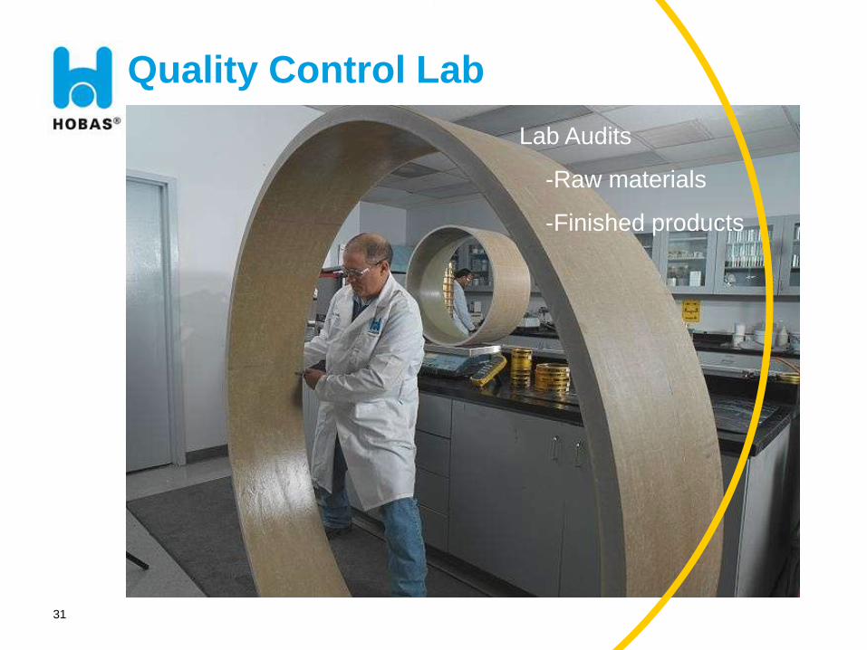
Quality Control Lab
Lab Audits
-Raw materials
-Finished products
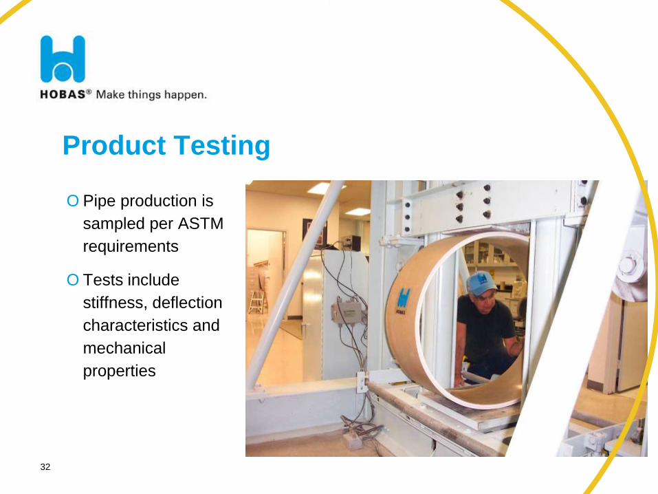
Product Testing
O Pipe production is
sampled per ASTM
requirements
O Tests include
stiffness, deflection
characteristics and
mechanical
properties
32
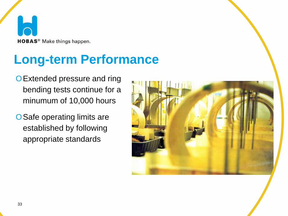
Long-term Performance
33
OExtended pressure and ring
bending tests continue for a
minumum of 10,000 hours
OSafe operating limits are
established by following
appropriate standards
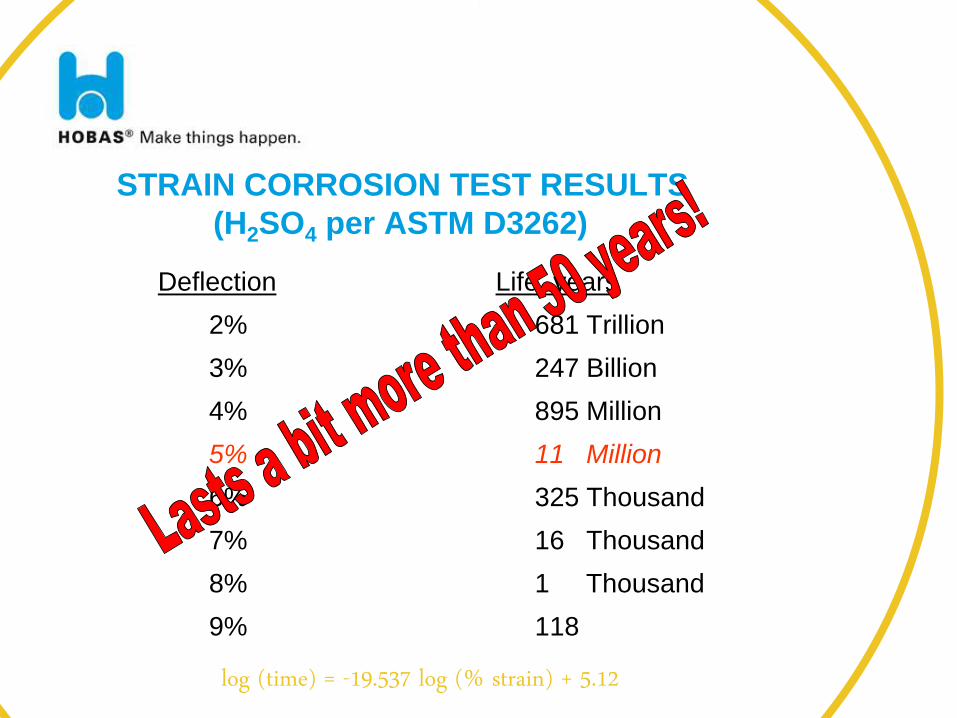
STRAIN CORROSION TEST RESULTS
(H2SO4 per ASTM D3262)
Deflection Life, years
2% 681 Trillion
3% 247 Billion
4% 895 Million
5% 11 Million
6% 325 Thousand
7% 16 Thousand
8% 1 Thousand
9% 118
log (time) = -19.537 log (% strain) + 5.12
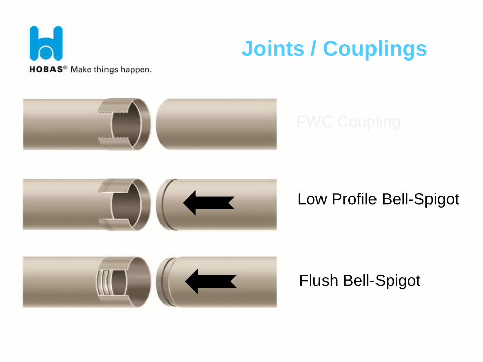
FWC Coupling
Low Profile Bell-Spigot
Flush Bell-Spigot
Joints / Couplings
BAP-HEA-090125-HAC IT 39
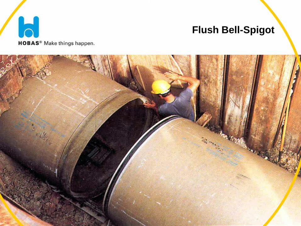
Flush Bell-Spigot
40
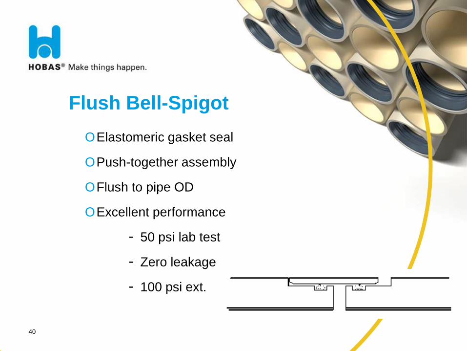
Flush Bell-Spigot
OElastomeric gasket seal
OPush-together assembly
OFlush to pipe OD
OExcellent performance
- 50 psi lab test
- Zero leakage
- 100 psi ext.
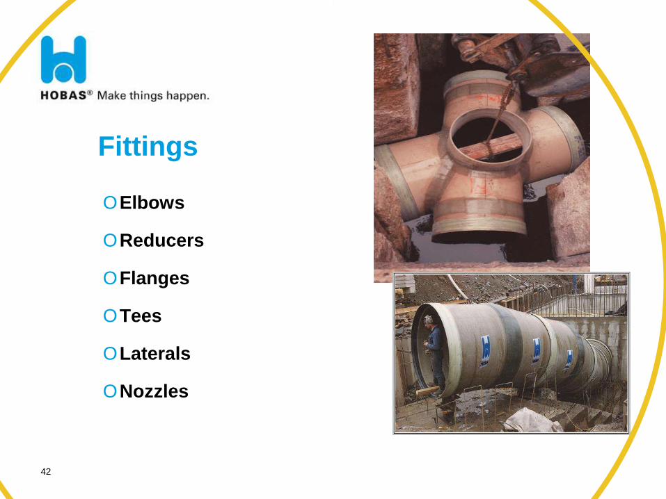
Fittings
42
OElbows
OReducers
OFlanges
OTees
OLaterals
ONozzles
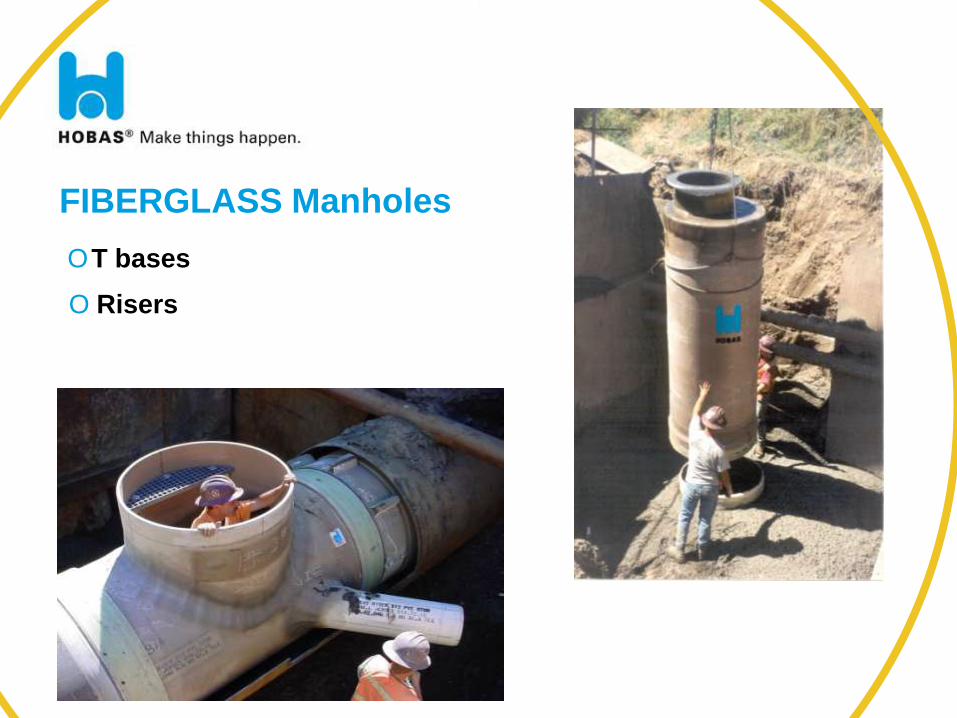
FIBERGLASS Manholes
BAP-HEA-090125-HAC IT 43
OT bases
O Risers
44
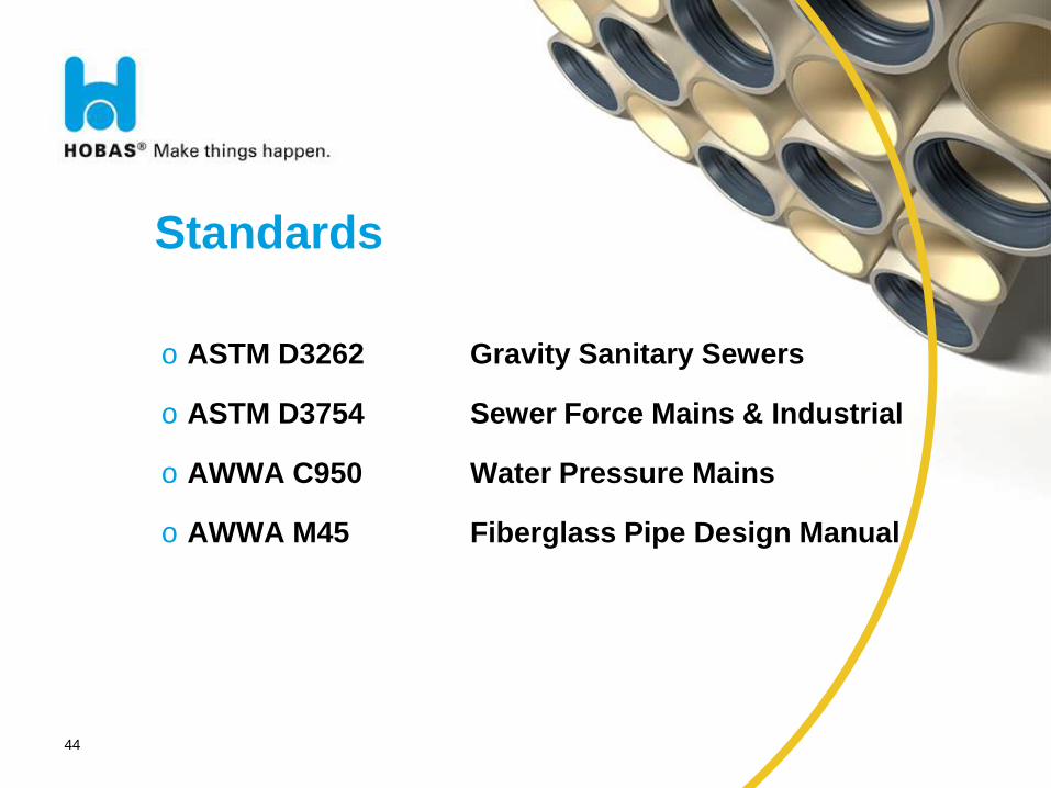
Standards
o ASTM D3262 Gravity Sanitary Sewers
o ASTM D3754 Sewer Force Mains & Industrial
o AWWA C950 Water Pressure Mains
o AWWA M45 Fiberglass Pipe Design Manual
45
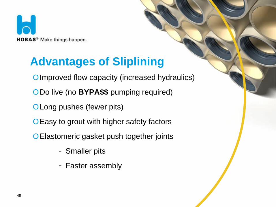
Advantages of Sliplining
OImproved flow capacity (increased hydraulics)
ODo live (no BYPA$$ pumping required)
OLong pushes (fewer pits)
OEasy to grout with higher safety factors
OElastomeric gasket push together joints
- Smaller pits
- Faster assembly
46
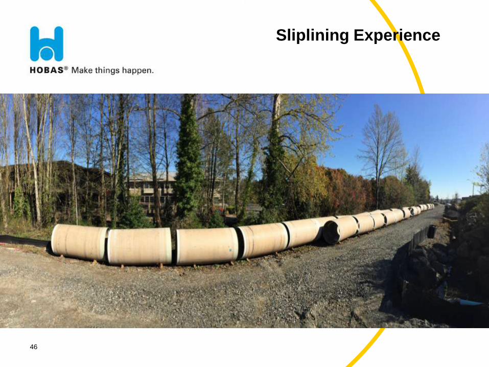
Sliplining Experience
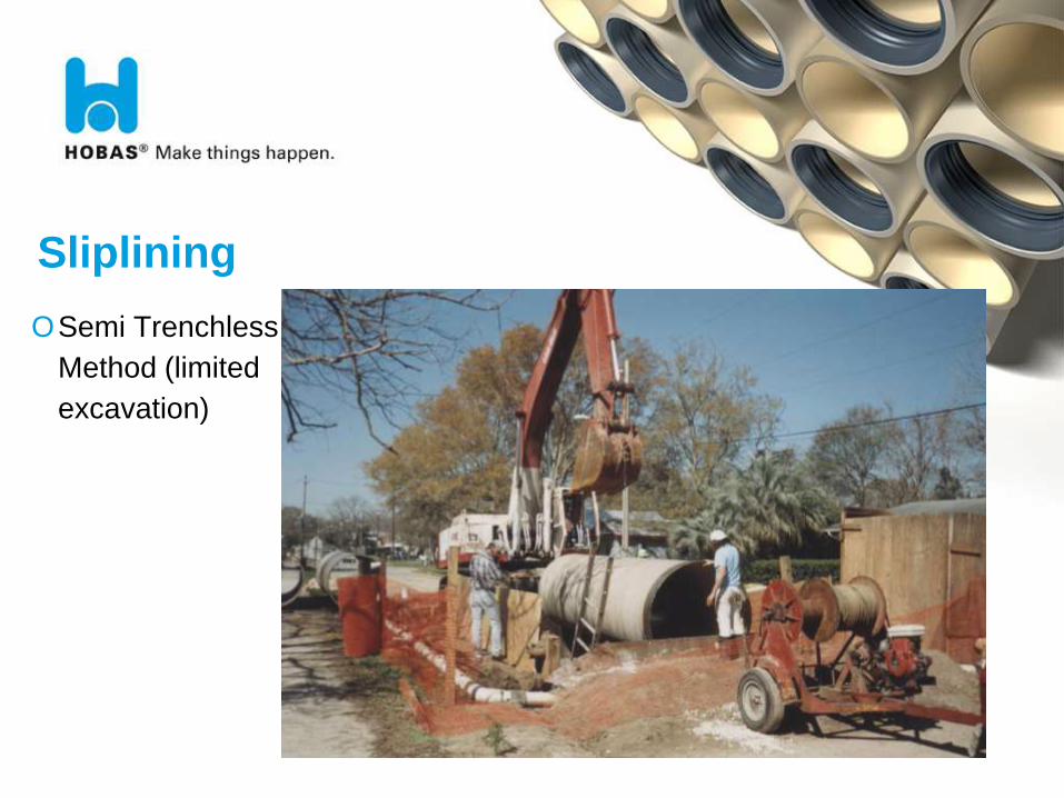
Sliplining
OSemi Trenchless
Method (limited
excavation)
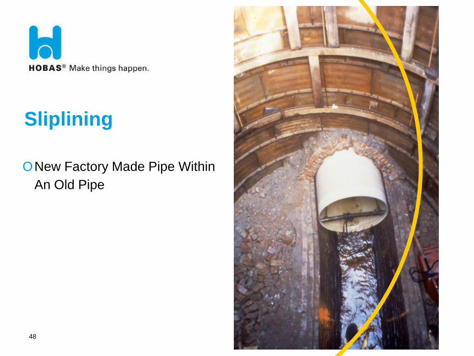
Sliplining
48
ONew Factory Made Pipe Within
An Old Pipe
49
Sliplining Experience
is this too fast?
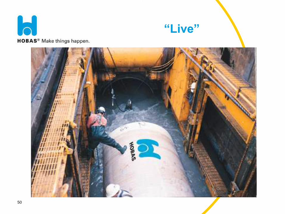
50
“Live”
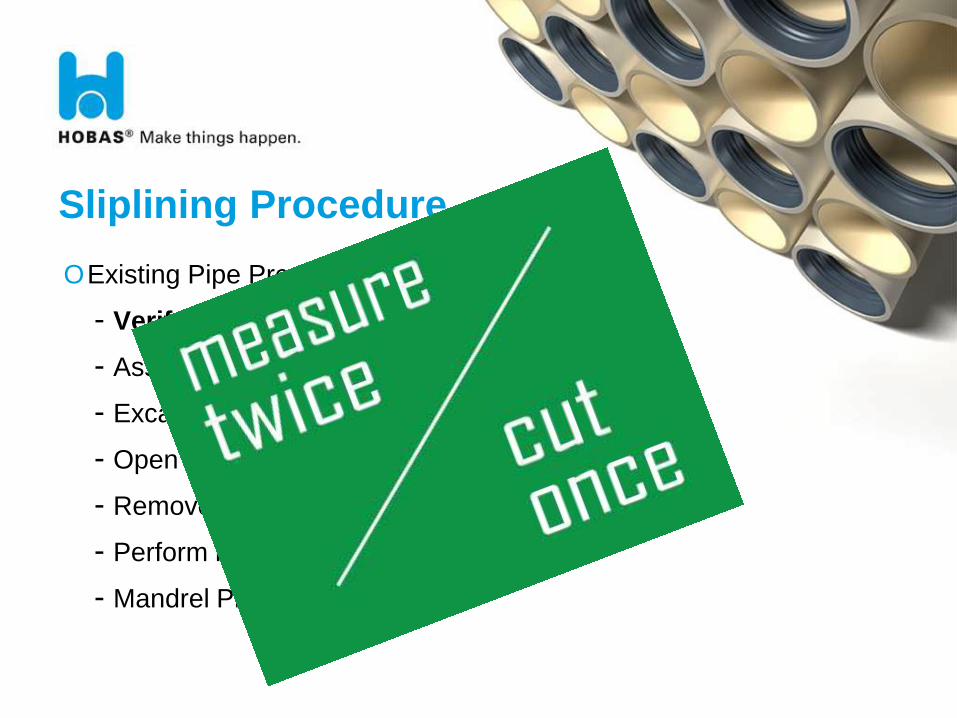
Sliplining Procedure
OExisting Pipe Preparation
- Verify Actual Host Pipe Diameter
- Assess Existing Pipe Condition (video)
- Excavate Access Shaft(s)
- Open Host Line
- Remove Debris & Obstructions (clean)
- Perform Point Repairs (if needed)
- Mandrel Proof
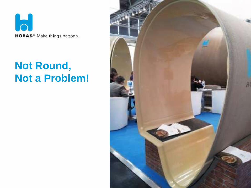
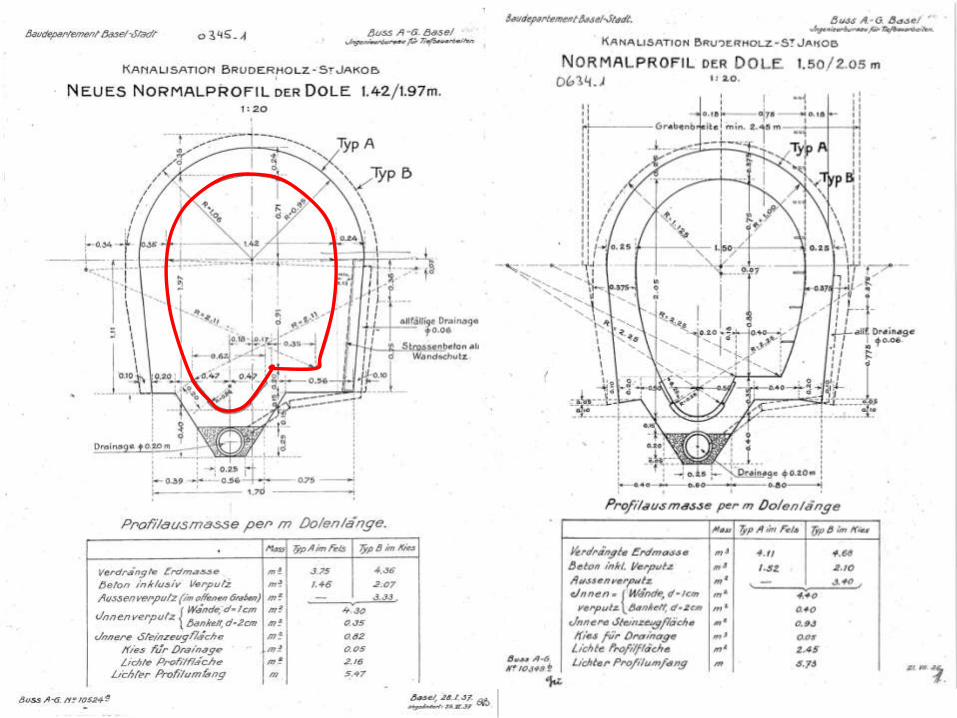
Not Round,
Not a Problem!
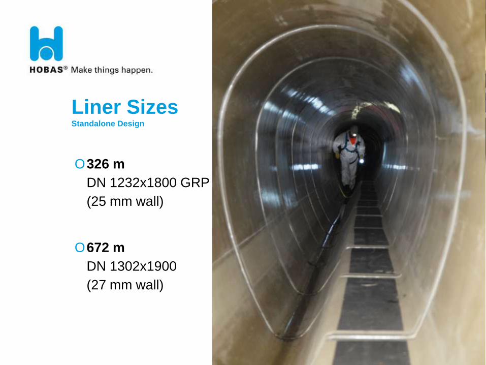
Liner Sizes Standalone Design
O326 m
DN 1232x1800 GRP
(25 mm wall)
O672 m
DN 1302x1900
(27 mm wall)
Sliplining Procedure
OLining Process
- Insert Liner Pipe
- Confirm Successful Insertion (video)
- Reinstate Any Laterals
- Grout Annulus
- Final Acceptance (video)
Design Considerations
OLiner
- Corrosion Protection
- Leak Prevention
- Hydraulics
- Structural Reinforcement
- Installation
Sliplining Advantages –
Segmental Pipes
OSegmented Systems (gasket sealed)
- Live Insertion
- Small Access Shafts
- Fast Assembly
- Quick Insertion
Most Common Questions…
59
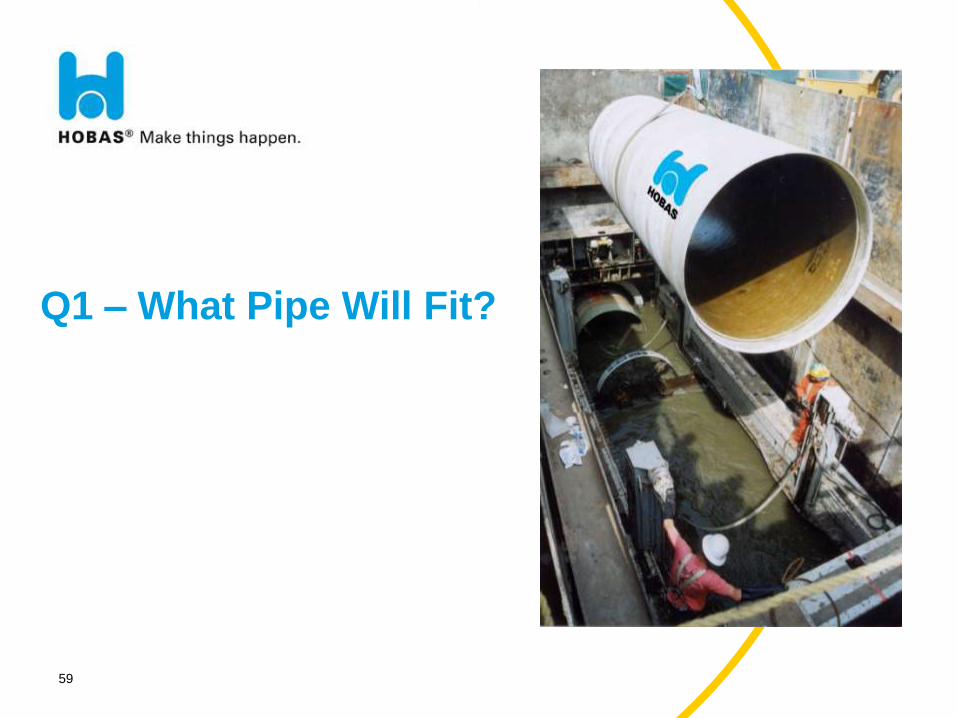
Q1 – What Pipe Will Fit?
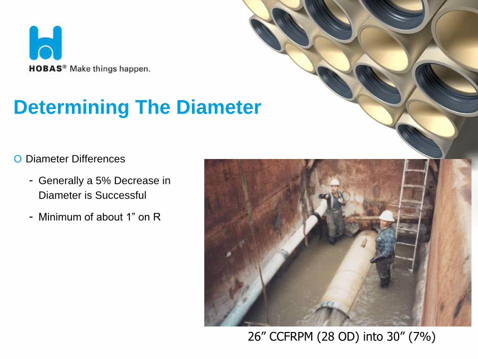
Determining The Diameter
O Diameter Differences
- Generally a 5% Decrease in
Diameter is Successful
- Minimum of about 1” on R
26” CCFRPM (28 OD) into 30” (7%)
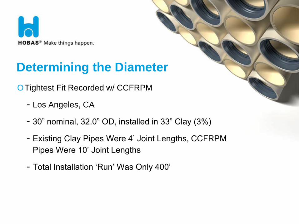
Determining the Diameter
OTightest Fit Recorded w/ CCFRPM
- Los Angeles, CA
- 30” nominal, 32.0” OD, installed in 33” Clay (3%)
- Existing Clay Pipes Were 4’ Joint Lengths, CCFRPM
Pipes Were 10’ Joint Lengths
- Total Installation ‘Run’ Was Only 400’
Non Straight Sections
O Determining if the pipes will pass through PI’s, Curves, Offsets
- Accurate Survey
- Pipe Dimensions (Raised or Flush Bell)
- Simply Geometry
- Mandrel “Proof”
O Determining if Pipes Will Seal if they pass
- Worst Case if Liner Pipe Joints Occur at Host PI’s
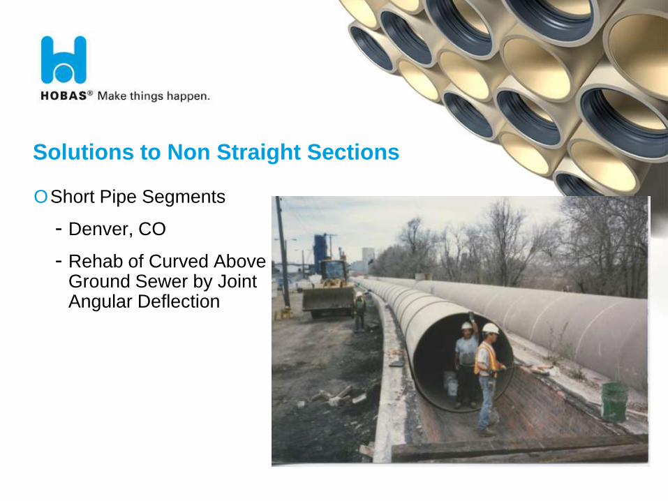
Solutions to Non Straight Sections
OShort Pipe Segments
- Denver, CO
- Rehab of Curved Above Ground Sewer by Joint Angular Deflection
64
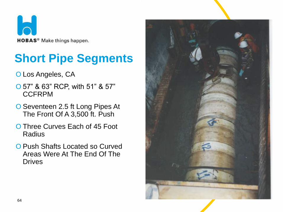
Short Pipe Segments
O Los Angeles, CA
O 57” & 63” RCP, with 51” & 57” CCFRPM
O Seventeen 2.5 ft Long Pipes At The Front Of A 3,500 ft. Push
O Three Curves Each of 45 Foot Radius
O Push Shafts Located so Curved Areas Were At The End Of The Drives
BAP-HEA-090125-HAC IT 65
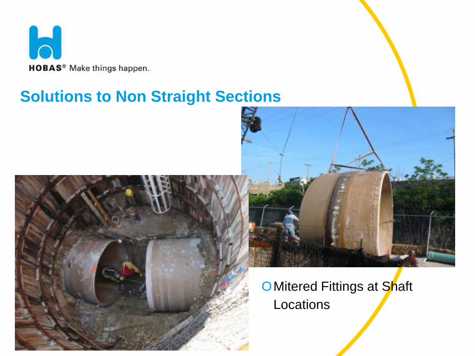
Solutions to Non Straight Sections
OMitered Fittings at Shaft
Locations
BAP-HEA-090125-HAC IT 68
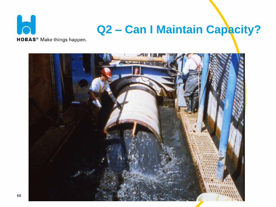
Q2 – Can I Maintain Capacity?
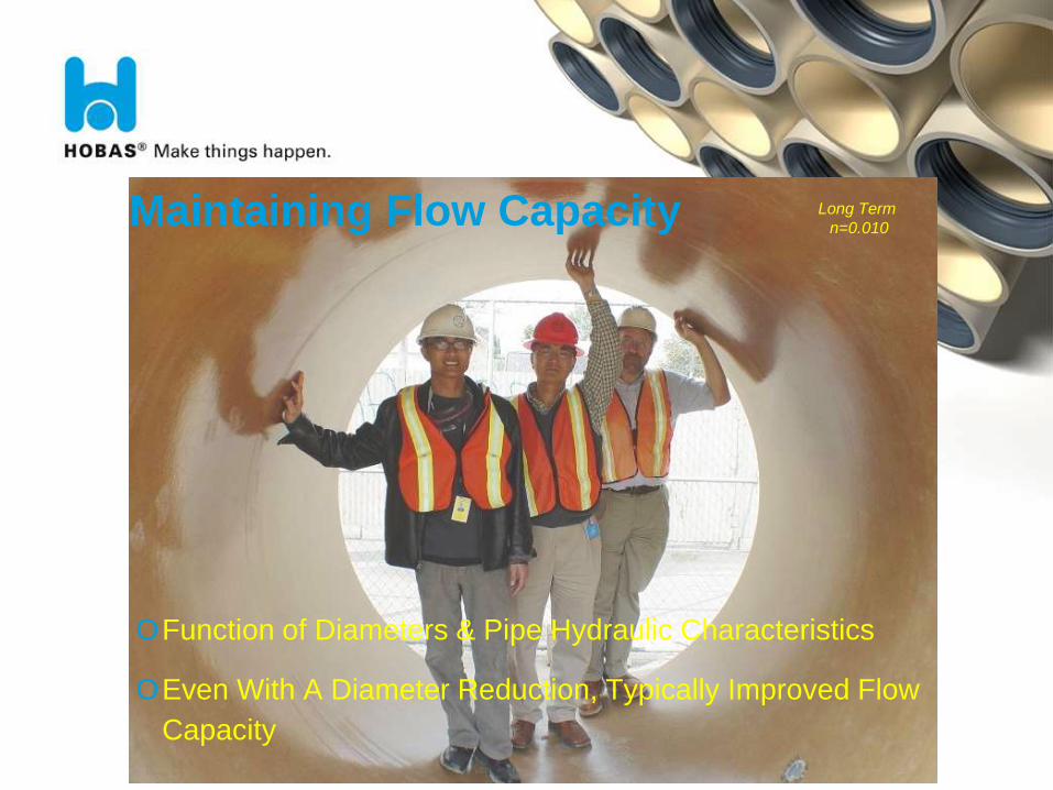
Maintaining Flow Capacity
OFunction of Diameters & Pipe Hydraulic Characteristics
OEven With A Diameter Reduction, Typically Improved Flow
Capacity
Long Term
n=0.010
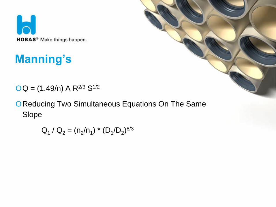
Manning’s
OQ = (1.49/n) A R2/3 S1/2
OReducing Two Simultaneous Equations On The Same
Slope
Q1 / Q2 = (n2/n1) * (D1/D2)8/3
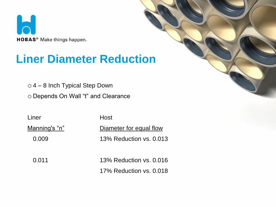
Liner Diameter Reduction
o 4 – 8 Inch Typical Step Down
oDepends On Wall “t” and Clearance
Liner Host
Manning's “n” Diameter for equal flow
0.009 13% Reduction vs. 0.013
0.011 13% Reduction vs. 0.016
17% Reduction vs. 0.018
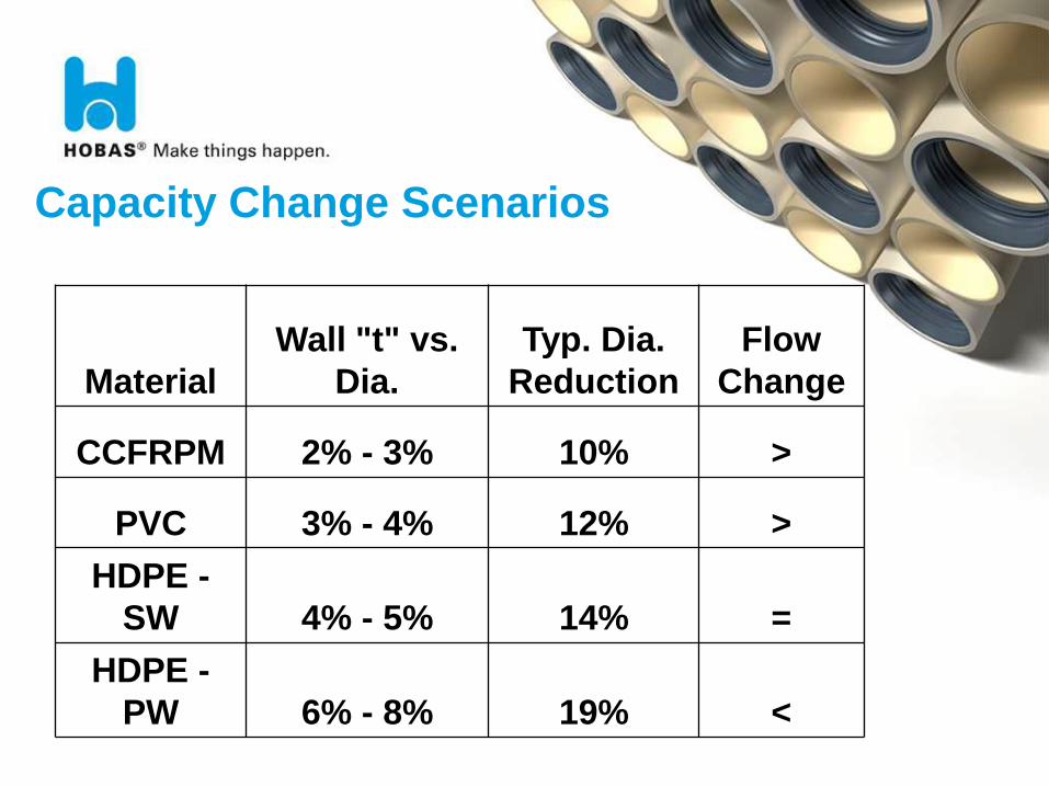
Capacity Change Scenarios
Material
Wall "t" vs.
Dia.
Typ. Dia.
Reduction
Flow
Change
CCFRPM 2% - 3% 10% >
PVC 3% - 4% 12% >
HDPE -
SW 4% - 5% 14% =
HDPE -
PW 6% - 8% 19% <
Where Did Flow Data Come From?
OWest Texas (Hazen Williams C=155)
OLACSD (Manning’s = 0.010)
74
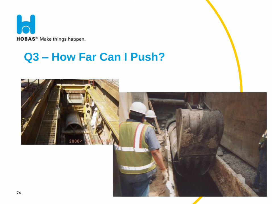
Q3 – How Far Can I Push?
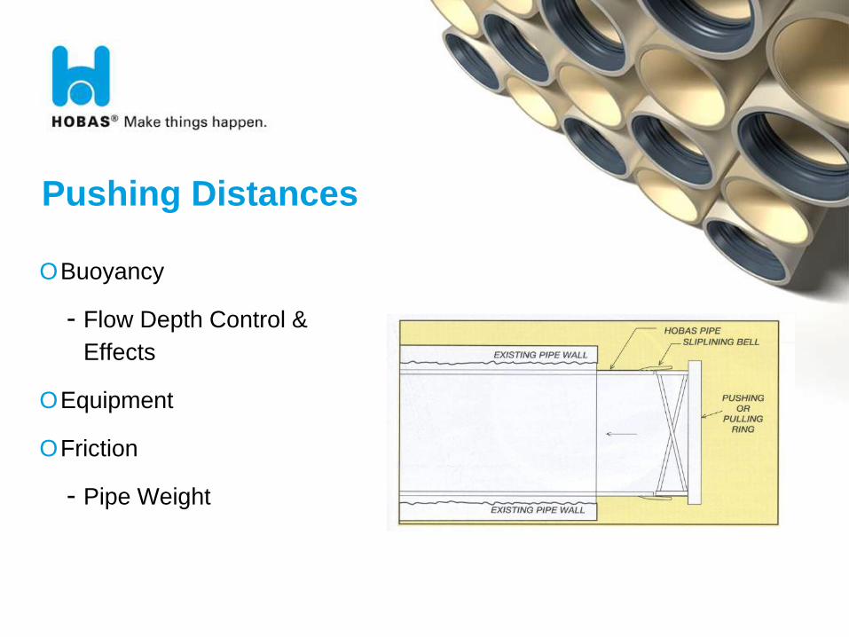
Pushing Distances
OBuoyancy
- Flow Depth Control &
Effects
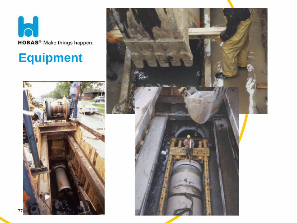
OEquipment
OFriction
- Pipe Weight
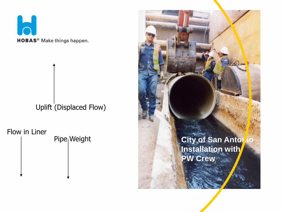
Pipe Weight
Uplift (Displaced Flow)
Flow in Liner City of San Antonio
Installation with
PW Crew
BAP-HEA-090125-HAC IT 77
Equipment
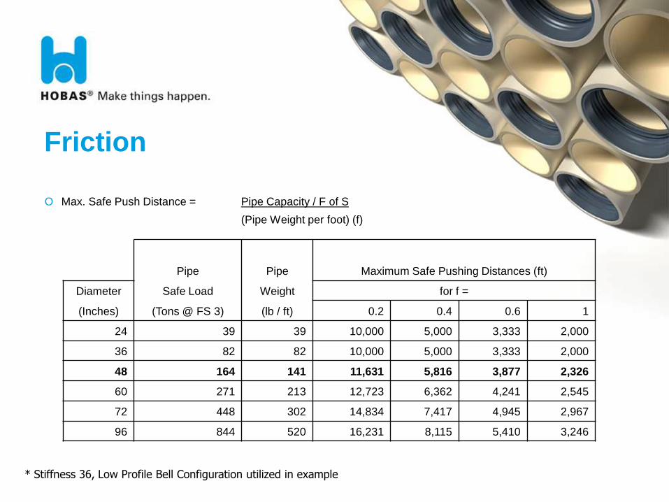
Friction
O Max. Safe Push Distance = Pipe Capacity / F of S
(Pipe Weight per foot) (f)
* Stiffness 36, Low Profile Bell Configuration utilized in example
Pipe Pipe Maximum Safe Pushing Distances (ft)
Diameter Safe Load Weight for f =
(Inches) (Tons @ FS 3) (lb / ft) 0.2 0.4 0.6 1
24 39 39 10,000 5,000 3,333 2,000
36 82 82 10,000 5,000 3,333 2,000
48 164 141 11,631 5,816 3,877 2,326
60 271 213 12,723 6,362 4,241 2,545
72 448 302 14,834 7,417 4,945 2,967
96 844 520 16,231 8,115 5,410 3,246
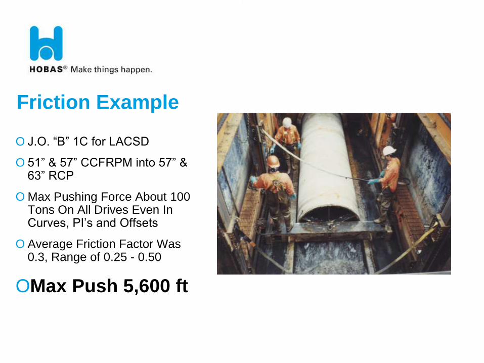
O J.O. “B” 1C for LACSD
O 51” & 57” CCFRPM into 57” & 63” RCP
O Max Pushing Force About 100 Tons On All Drives Even In Curves, PI’s and Offsets
O Average Friction Factor Was 0.3, Range of 0.25 - 0.50
OMax Push 5,600 ft
Friction Example
Sliplining Advantages OSliplining Can Provide:
- Leak Free Service
- Eliminate Corrosion Deterioration
- Restore Structural Integrity
- Only General Cleaning To Allow Liner Insertion
- No Surface Cleaning or Dependence on Bond
OPreserving Capacity
OLong Insertion Pushes
- Minimal Surface Disruption

81
Case Study: Sliplining
Over 1,200,000 LF in Service
(365,000 m)
BAP-HEA-090125-HAC IT 82
Intercepting Sewer Rehab
Evanston, IL
o Deteriorating 120- inch semi-elliptic cast-in-place concrete
sewer
o Needed to restore hydraulic and structural integrity
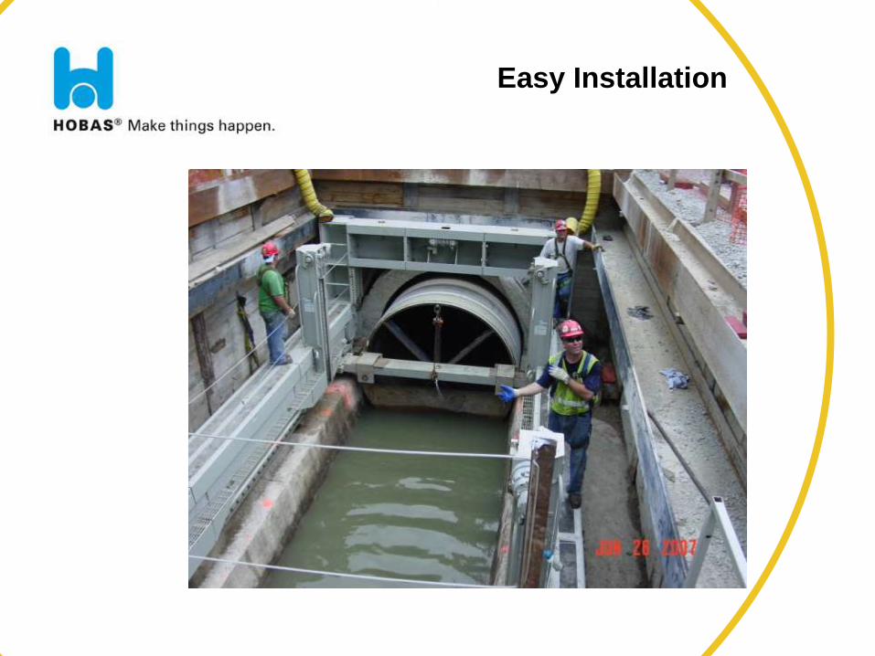
Easy Installation
BAP-HEA-090125-HAC IT 84
Intercepting Sewer Rehab
Evanston, IL
o 7,000 feet of 110- and 104-inch
o Flexible manufacturing allowed for a reduction in diameter
after the job had started
o Only two shafts
o 10 foot sections were provided in addition to the 20 foot
sections
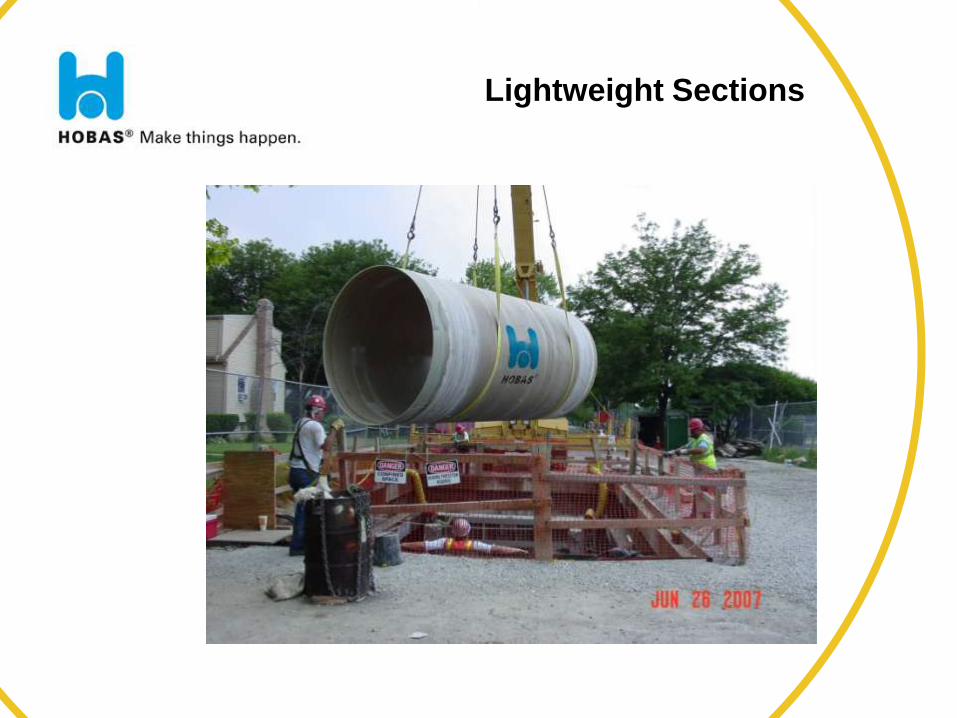
Lightweight Sections
Summary
If you need....
o Corrosion resistance
o Long life
o Leak-free joints
o Structural reliability
o High flow capacity
o Easy installation
o Lower life cycle cost
o Consistent high quality
o Superior service
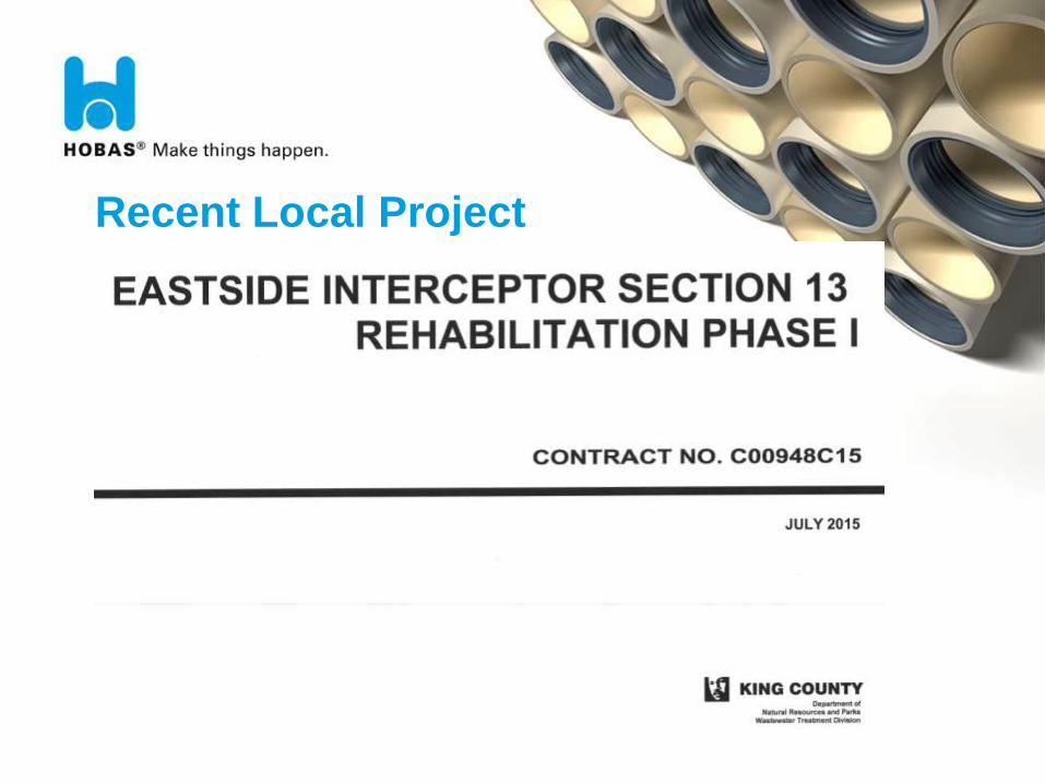
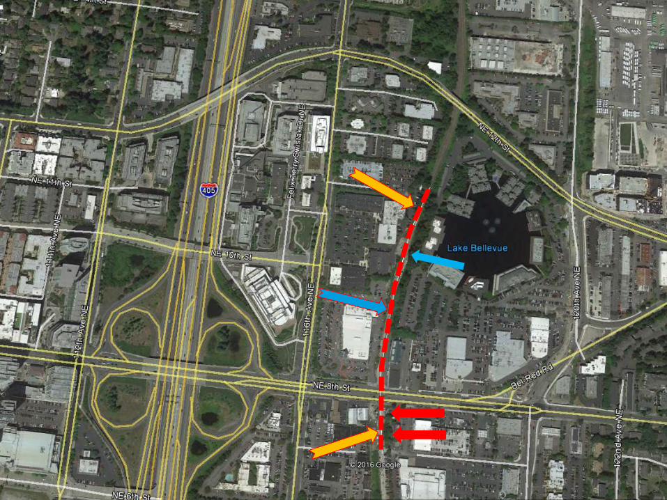
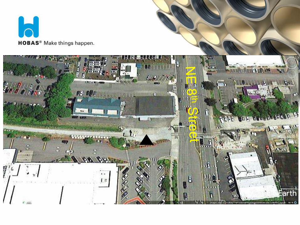
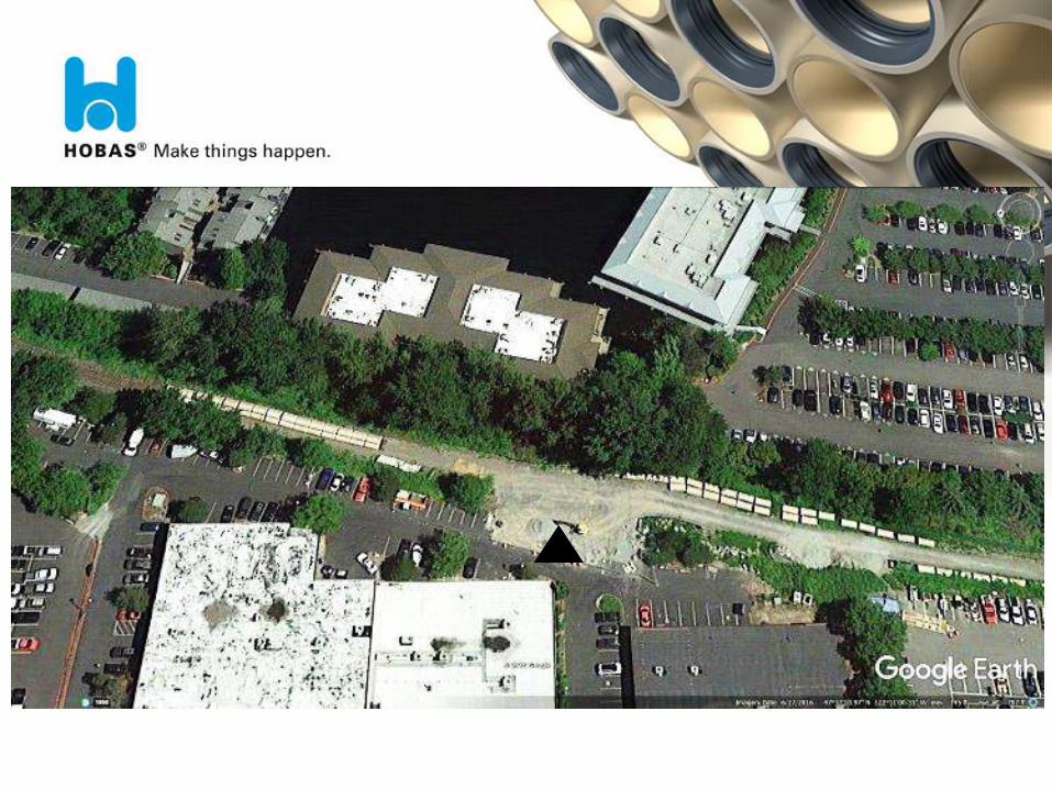
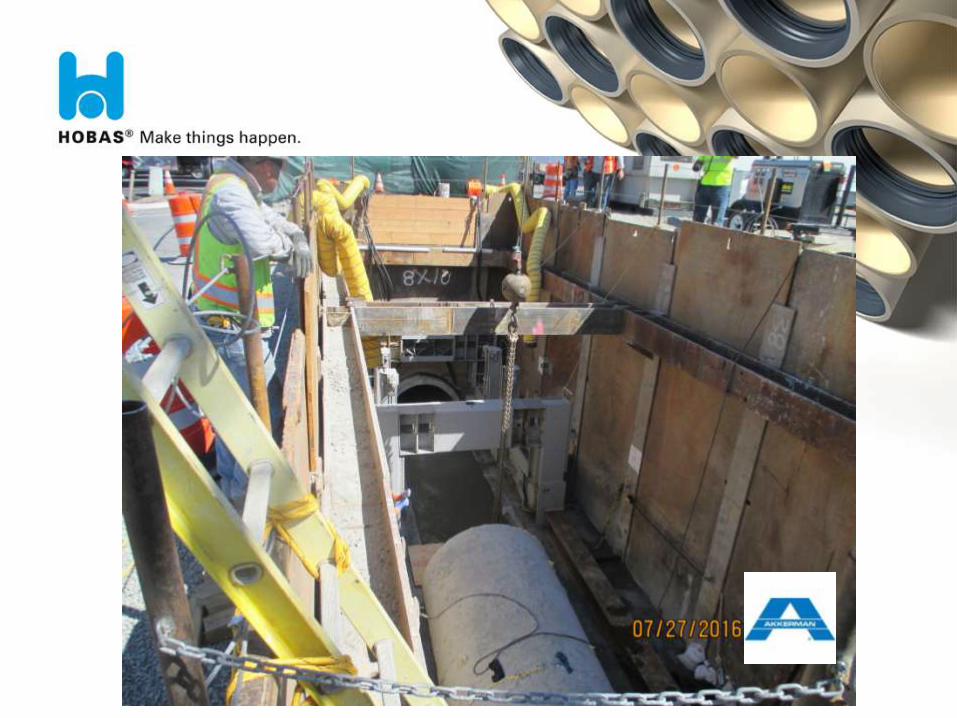
Recent Local Project
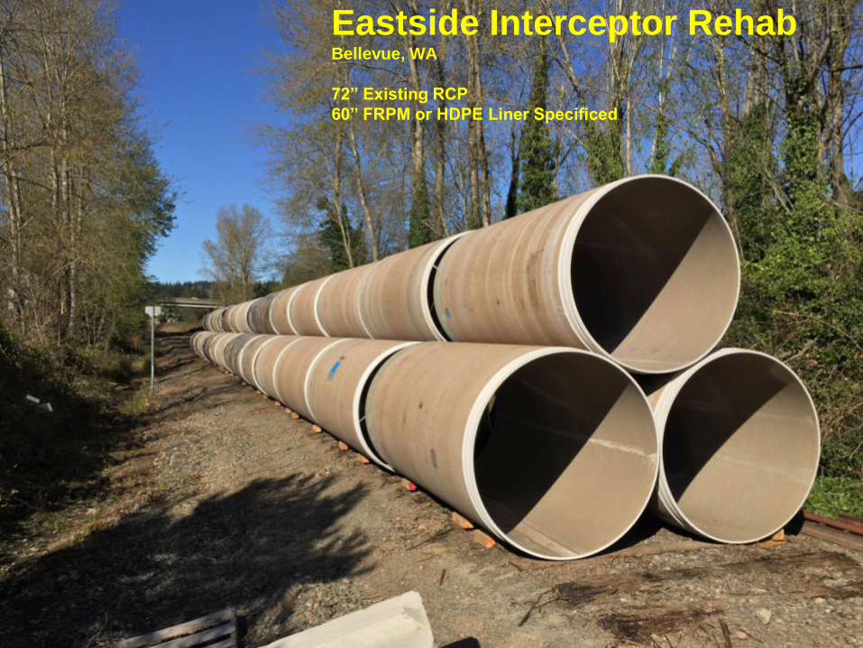
Eastside Interceptor Rehab Bellevue, WA
72” Existing RCP
60” FRPM or HDPE Liner Specificed
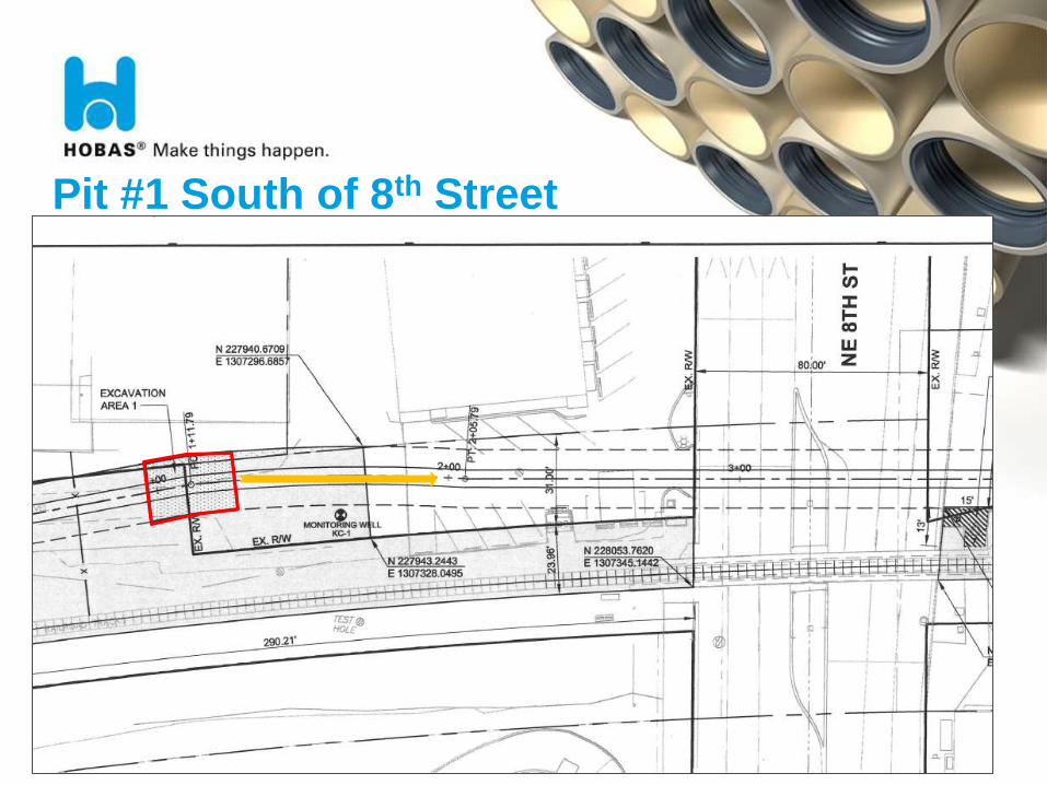
Pit #1 South of 8th Street
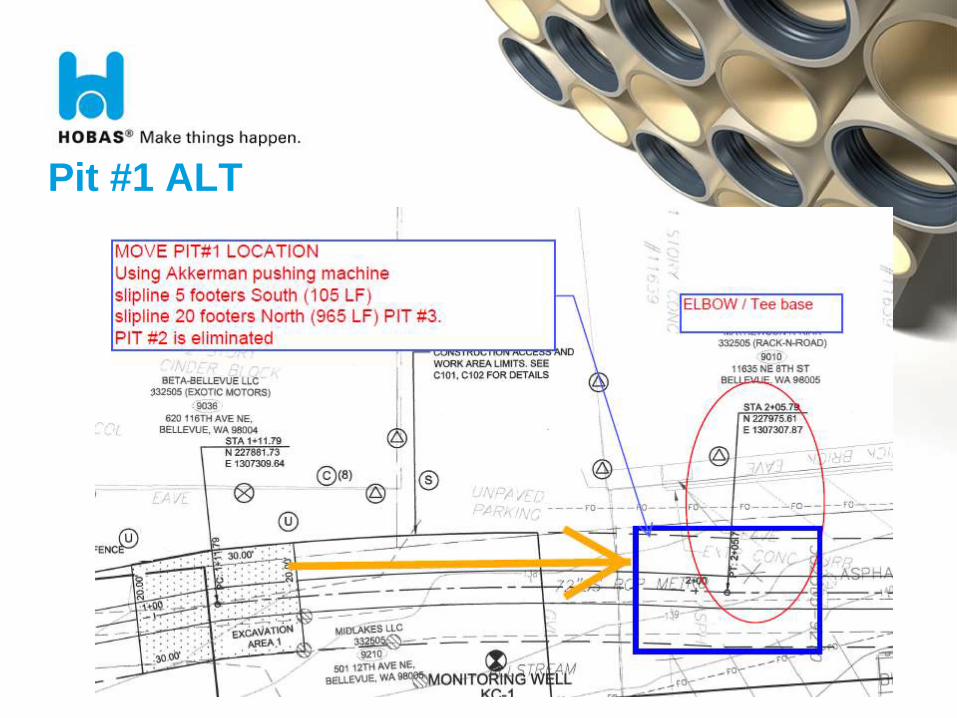
Pit #1 ALT
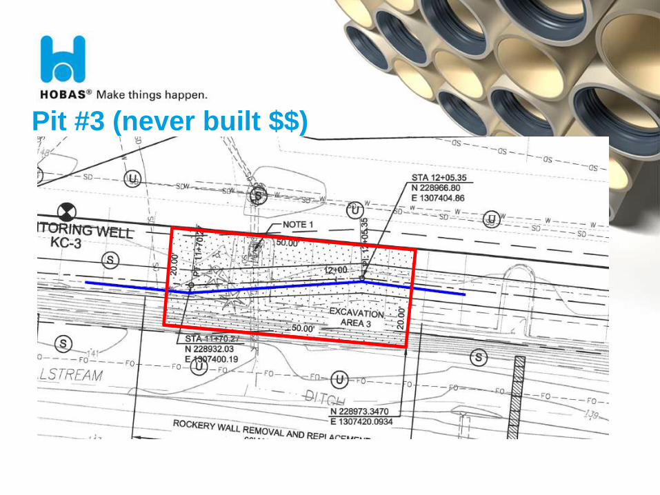
Pit #3 (never built $$)
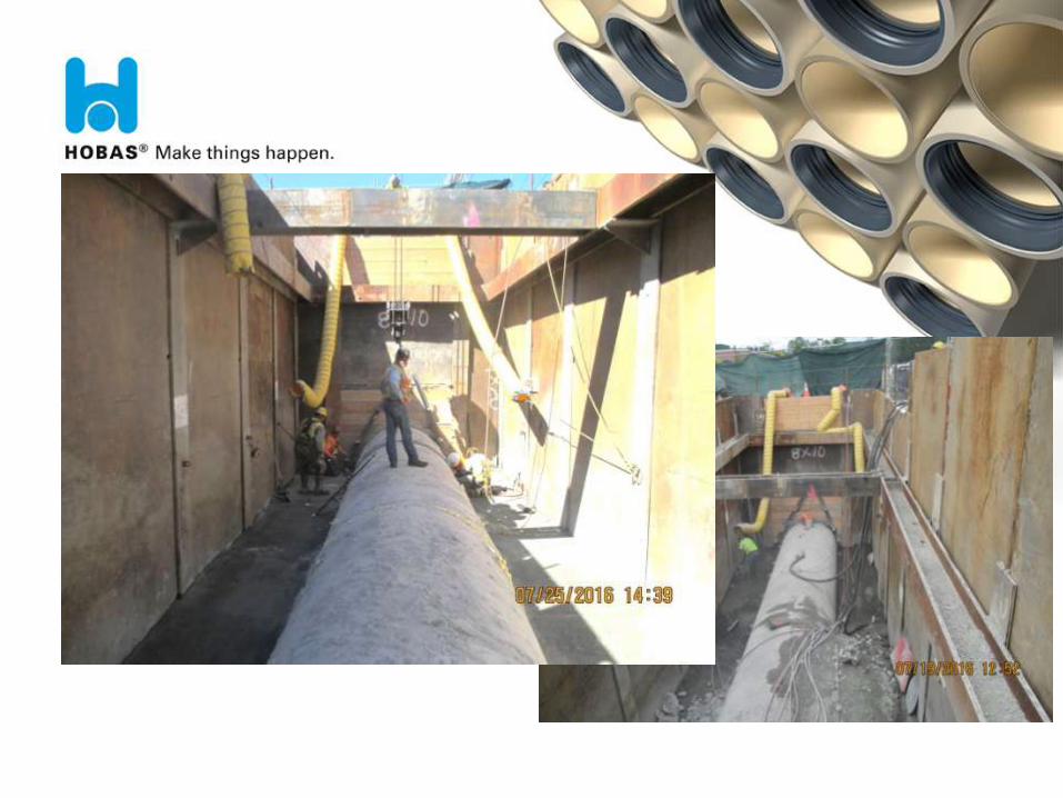
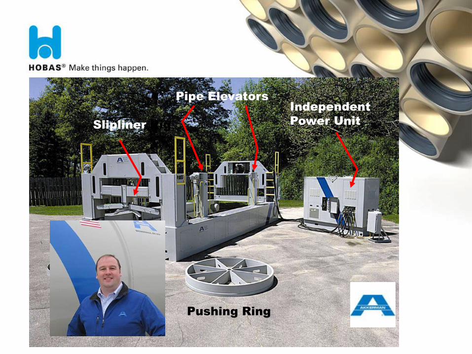
Independent
Power Unit Slipliner Rig
Pipe Elevators
Pushing Ring
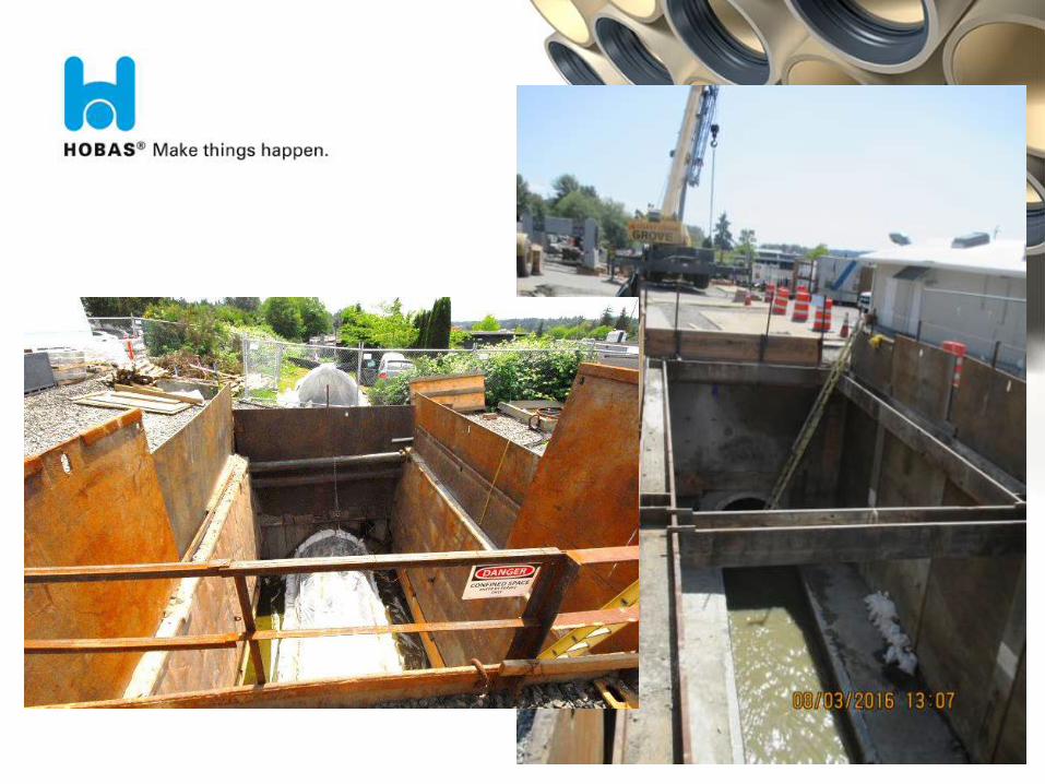
Lessons Learned
OProblems
- Unknown Angle Points (Pit #1A - Requiring an Extra Pit $$
- Poor Ground Conditions at Pit #3 – Difficult pit built $$
OSolutions
- Provide a complete survey with the bid docs.
- Provide a complete geo-tech report with the bid docs.
(OLD CREEK BEDS ARE NOT CONTRACTOR FRIENDLY)
f
Leftover pipe, special tee and couplings
HOBAS PIPES are your best value
QUESTIONS AND ANSWERS


![Sewer Processes and Design - SKYSCRAPERS · 2018-09-02 · SANITARY SEWER SYSTEM [Foul Sewer] I. Storm Sewer System STORM SEWER is designed to drain excess rainfall and groundwater](https://img.pdfslide.us/doc/110x75/5e9b180035942256b30ec806/sewer-processes-and-design-skyscrapers-2018-09-02-sanitary-sewer-system-foul.jpg)