Embed Size (px)
Citation preview
Tailor Made Concrete Structures – Walraven & Stoelhorst (eds)© 2008 Taylor & Francis Group, London, ISBN 978-0-415-47535-8
Slipforming of advanced concrete structures
K.T. FossaAker Kvaerner, Oslo, Norway
A. KreinerGleitbau, Salzburg, Austria
J. MoksnesJan Moksnes Consulting, Stavanger, Norway
ABSTRACT: Slipforming is a method of constructing tall concrete structures based on known parametersand proven technology. The method encompasses several activities and the successful execution of a slipformoperation depends on proper understanding of the mechanisms involved, careful planning and work preparationand the skills of the operator. Slipform operations are often executed by specialist subcontractors. Recent advancesin concrete technology, pump line equipment and formwork design enable the method to be employed in the rapiderection of tall and demanding concrete structures, but schedule and quality advantages can also be achieved forstructures of more ordinary size and complexity. The paper describes the important parameters for successfulslipforming and contains some examples of slipforming of advanced concrete structures.
1 INTRODUCTION
Slipforming is a highly efficient method of construct-ing tall concrete structures. Rates of construction ofseveral meters per day of varying geometrical shapesand cross sections and containing multiple inserts andopenings can be achieved within strict geometricaltolerances. Slipforming is labour intensive over shortperiods, but when properly planned and executed itoffers significant advantages with respect to overallconstruction time, quality and safety.
The method has made great progress during the pastdecades, particularly in relation to the large concreteplatforms and storage tanks delivered to the oil andgas industry and for tall concrete buildings, chimneysand pylons. Progress in the field of high performanceconcrete, formwork design and pump line technologyare some of the key elements.
Slipforming is a construction process of many inter-dependent items. The essential elements are properplanning, a well designed concrete mix with uniformand predictable properties, a distribution system ensur-ing uniform and timely delivery of all components, anda strong and durable slipform assembly lifted at a pre-determined speed commensurate with the setting timeof the concrete mix. The system must have adequaterobustness to cope with the changing conditions andoccasional conflicts of interest for the many activitieson a construction site.
For tall structures involving considerable overheadcrane activities special attention must be paid to safetyby proper fences and railings, clearly marked accessesand proper housekeeping on the work decks. In thisrespect a slipform assembly with a permanent lay outfrom start to finish offers some potential for improvedsafety compared to conventional forms installed insections and served by constantly moving crews andequipment.
2 THE BASIC PRINCIPLE OF SLIPFORMING
The essential elements of a slipforming assembly aretwo parallel wall panels (about 1, 2 m tall) supportedby steel frames and horizontal yokes connected tohydraulic jacks – ref. Figure 1. The jacks climb on ver-tical steel rods at a rate of some 15 mm per stroke. Thespacing of the two panels determines the wall thicknessand can be varied by screw type controls. The geom-etry of the concrete structure can vary from straightwalls to circular cells and towers of varying diame-ter and geometrical shape. The steel reinforcement,inserts and box outs are placed inside the wall panelsas they are continuously being lifted by the jacks andas the concrete is placed in layers of uniform thickness.The main key to a successful operation is the abilityto synchronise and control the concrete setting time
831

Figure 1. Typical slipform assembly.
and the lifting rate of the assembly, so that the layersof concrete set and harden shortly before they emergebelow the wall panels and not before. A faster liftingrate produces a better surface quality and less surfacepatching and repairs.
Modern slipform technology enables a variety ofshapes and forms to be produced to within strict geo-metrical tolerances. In general, the walls are verticaland of uniform thickness. If required, however, theshape and wall thickness can be varied in a seamlessmanner as the work progresses by means of screw typecontrols and overlapping wall panels. A typical exam-ple of this technology is the flared shafts of the offshoreplatforms designed for minimum cross section areasat the water line.
From a quality point of view the method offers con-siderable advantage over conventional formwork byperforming all operations near the top of the form,where access is easy for the operators performing thework and for inspection. The quality of the concreteis ensured through controlled placing, repeated com-paction of the successive layers and systematic curingby water spray or membranes. The concrete cover to
Figure 2. Slipforming of the Telecom Centre Munich BRD(2003) showing large box outs and openings.
the rebars is determined by spacers mounted on theforms and is readily controlled.
For marine structures subjected to one sided waterpressure slipforming offers the notable advantage ofeliminating all horizontal construction joints. Con-struction joints are notorious trouble spots for waterleakage and durability issues, particularly for marinestructures where chlorides may penetrate to the rein-forcing steel, destroy the passivity provided by theconcrete cover and initiate corrosion.
Slipforming offers the advantage of speed of con-struction, tall structures being erected in a few weeksrather than several months. Slipforming also has someinherent advantages with respect to safety as the workface never changes significantly and the operatorsreturn to a familiar workplace where safety is assuredby semi-permanent stairs and lifts, proper railings, andeasy access to the working areas.
Slipforms can accommodate large box outs fortemporary or permanent openings in the concretestructure enabling subsequent installations of associ-ated components or structural members, as shown infigure 2.
832
3 THE SCIENCE OF SLIPFORMING
A shear zone will be formed close to the slipformpanel when the slipform panel is lifted. This zone con-sists of smaller particles (cement paste mixed withsand) and act as a lubricant during the plastic phasein the concrete. When the slipform is lifted, the liftingforce is primarily affected by the particle shape of theaggregates and the workability of the fresh concrete.
In order to lift the slipform panel, the lifting forceneeds to overcome the static friction in the shear zone.When the panel starts to move, the friction decreasesto a lower level called sliding friction. The friction canbe calculated using the friction law because the fric-tion coefficient is approximately constant for a givenconcrete and slipform set-up. This means that the fric-tion force that occurs when the slipform panel is lifteddepends primarily on the effective pressure betweenthe particles. A simplified model for the relationshipbetween the friction and the effective pressure is (1):
where F = friction [Pa]σ ′ = effective pressure[Pa]µ = coefficient of friction
The effective pressure is the difference between thenormal pressure (concrete pressure against the slip-form panel) and the pore water pressure, see Eq. 2:
where σ = normal pressure [Pa]σ ′ = effective pressure [Pa]u = pore water pressure [Pa]
The pore water pressure represents the pressure in theliquid phase in the concrete. The primary driving forcefor the change in the pore water pressure is the chem-ical shrinkage caused by the cement hydration. Theeffect of the chemical shrinkage on the pore waterpressure is assumed to depend on the geometry of thepore system that is formed and the pressure equilib-rium between air and water. When chemical shrinkageis developing, contraction pores are formed since thereaction products have a smaller volume than the react-ing materials. The pore water pressure will decrease asa result of the developed contraction pores.
The existing air content in the concrete will reducethe effect of the chemical shrinkage on the pore waterpressure because the air content in the concrete will bein equilibrium with the liquid system in the concrete.
In general the friction that occurs during liftingdepends mainly of the concrete mix composition, thelifting rate of the slipform and also the slipform set-up.A concrete mix with lower air content or higher con-tent of fines will give higher friction force.The friction
force will also increase with lower slipform rate (lowerlifting frequency or lower lifting height). Also unsta-ble concrete or heavy vibration of the concrete in theform will increase the friction force between the con-crete and the slipform panel during lifting. The riskfor any surface damage on the concrete structure canbe assumed to increase with increasing friction forceduring lifting of the slipform. Poker vibrators shouldnot be employed in the cover layer outside the mainreinforcement.
4 PLANNING AND EXECUTION OF THEWORK
Most construction projects involve contributions bya number of contractors, subcontractors and suppli-ers. Typically concrete production (often off-site),transport and delivery into the forms, installation ofreinforcing steel and prestressing, slipform installationand operation, supply of labour and site managementmay be performed by different companies. The prop-erties of the concrete, the stability of the mix duringtransport and handling, the performance of the slip-form assembly and the lifting rate of the slipform areclosely interrelated so that a common understandingof the process and efficient management are key fac-tors for a successful operation. A jointly prepared andimplemented Method Statement is an essential tool toachieve efficiency and quality.
Careful planning of the logistics of all materialsand components required is required. The rebars andembedments shall be lifted on to the form in the rightorder and so that they do not overload the slipformassembly. A lifting plan sorted by elevation is a use-ful tool in order to control the loads and hence thedeformations of the assembly.
The choice of distribution system for the concreteis important. For a conventional crane and bucketdelivery the crane capacity must be adequate to avoidbottle neck situations in other areas. More advancedsystems of distribution by pump lines into hopperson the deck or by pump lines with vents discharg-ing straight into the form offer significant advantages,but are vulnerable with respect to unexpected stopsand slow deliveries causing changes to the concreteproperties and blockages in the system. In a well man-aged slipform operation pipeline delivery into the formwill reduce manpower requirements and improve theoverall performance.
The lifting rate must be determined with regard tothe supply of all the components and the availabil-ity of manpower, so that interdependent activities canproceed without hold ups. The concrete properties canthen be chosen to match the chosen mode of deliveryand rate of lifting. The setting time of the concretecan be adjusted within wide limits (up to 24 hours)by means of chemical admixtures and temperature
833
control, and the clue to success is to fully synchro-nize the prescribed setting time of the concrete andthe lifting rate of the form.
The temperature of the fresh concrete can beadjusted by cooling or heating systems at the batchingplant and the curing conditions for the slipform can beadjusted by wind or sun shields or by external heaters.The total temperature regime will have a bearing onthe all important concrete setting time, additional towhat can be achieved by chemical admixtures.
A mock-up should always be considered when newmaterials, methods or systems are being employed. Amock-up will pay dividends for the training of inex-perienced crews. If pipe line distribution is adopted,pumping trials in advance will assist the concrete mixdesign and prevent problems.
5 CONCRETE CONSTITUENTS AND MIXDESIGN
Successful slipforming depends on the delivery ofa high performance concrete with uniform and pre-dictable properties. Essentially this means high bindercontent, well graded aggregates with adequate fines,and admixtures ensuring high workability and con-trolled and adjustable setting time. Supplementarybinders such as fly ash and silica fume often proveadvantageous, particularly if the concrete is deliveredby pump lines. Concrete mix design and full scale sitetrials are essential elements in the planning process;several examples of less than successful operations canbe attributed to unsatisfactory concrete properties andabsence of site trials. The minimum material require-ments stipulated in the mandatory Codes will not beadequate to assess fitness for advanced slipforming.
Uniform and predictable properties can only be con-sistently delivered by an efficient batching plant withautomated batching of all components and monitoringof workability and temperature.
The essential slipform properties of the fresh con-crete can be defined by 3 s’s;
• Slump (or workability)• Setting time (at all times tailored to the intended
lifting rate)• Stability (absence of segregation)
A high slump, approaching that associated with selfcompacting concrete (240 mm), is commonly adoptedand promotes easy handling of the concrete on site.Thestability item refers to the need for the mix to remainworkable also during stops in the pump line delivery.Air-entrainment, which may be a requirement for dura-bility in cold regions, has proven to be beneficial alsoto the pump line performance of the concrete.
Tests on drilled out cores from several projectshave shown that the slipform methodology of concrete
layers being placed in the top of the form and repeat-edly compacted by poker vibrators can yield up to 20%increase in the obtained in-situ strength, compared toa conventionally placed concrete (2).
6 THE SUCCESS CRITERIA
As discussed above, it is convenient to considerthe slipform operation as consisting of three mainelements:
a) The concreteb) The batching, transporting, placing, compacting
and curing of the concretec) The shape, size and speed of the slipform.
The properties and performance within each ofthese categories impact significantly on the other twoand determines the robustness of the operation. Rec-ognizing this relationship is important and will governa series of decisions in the planning process. Highperformance slipform concrete is not a standard prod-uct available from a regular all purpose plant, butrequires detailed mix design and testing before it canbe accepted. There are some clear examples of theconcrete mix not being compatible with the chosenequipment and methods, resulting in lifting cracks andsurface imperfections and costly repairs. Such imper-fections are generally confined to the concrete cover,seldom extending beyond the main reinforcement orcreating doubts about the structural integrity of thewall in question.
An inherent advantage in a slipform operation isthat, in principle, the slipform never stops. Once theoperation has started and the form has had lift-off thework goes on and problems get resolved, unless theybecome insurmountable and a stop and a very undesir-able cold joint occurs. The slipform thus provides anindirect driving mechanism to the construction sched-ule by virtue of the non-compromising need for allparties to meet their part of the contractual obliga-tion. Cold joints can be managed but require extensivecleaning of the joint and additional starter bars. Backup procedures for unexpected stops should thereforebe included in the Method Statement.
The simple control procedure of measuring thedepth of wet concrete in the form (ideally 80 cm)decides if the concrete setting time needs to be adjustedor the lifting speed has to altered. A uniform and pre-dictable speed and depth of wet concrete improves theoverall efficiency of the operation. The general rule is:a fast and uniform lifting rate gives the best quality andfew surface repairs. Any repairs, surface installationsor applications of coatings should be performed fromthe suspended working decks (ref. Figure 1) as thework progresses, thus eliminating the need for costlyaccess at a later date.
834
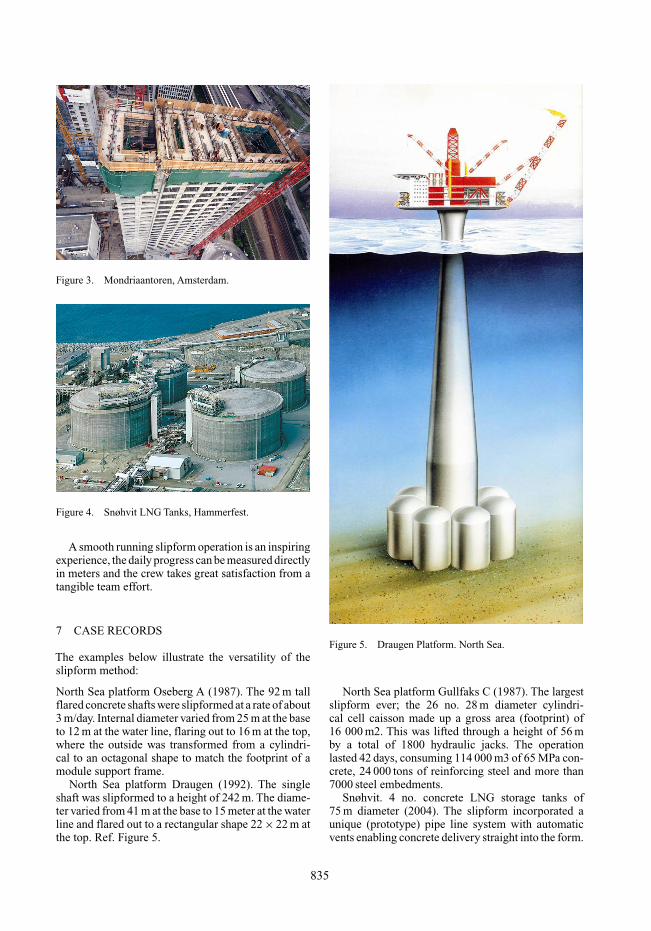
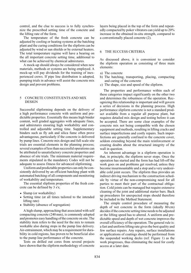
Figure 3. Mondriaantoren, Amsterdam.
Figure 4. Snøhvit LNG Tanks, Hammerfest.
A smooth running slipform operation is an inspiringexperience, the daily progress can be measured directlyin meters and the crew takes great satisfaction from atangible team effort.
7 CASE RECORDS
The examples below illustrate the versatility of theslipform method:
North Sea platform Oseberg A (1987). The 92 m tallflared concrete shafts were slipformed at a rate of about3 m/day. Internal diameter varied from 25 m at the baseto 12 m at the water line, flaring out to 16 m at the top,where the outside was transformed from a cylindri-cal to an octagonal shape to match the footprint of amodule support frame.
North Sea platform Draugen (1992). The singleshaft was slipformed to a height of 242 m. The diame-ter varied from 41 m at the base to 15 meter at the waterline and flared out to a rectangular shape 22 × 22 m atthe top. Ref. Figure 5.
Figure 5. Draugen Platform. North Sea.
North Sea platform Gullfaks C (1987). The largestslipform ever; the 26 no. 28 m diameter cylindri-cal cell caisson made up a gross area (footprint) of16 000 m2. This was lifted through a height of 56 mby a total of 1800 hydraulic jacks. The operationlasted 42 days, consuming 114 000 m3 of 65 MPa con-crete, 24 000 tons of reinforcing steel and more than7000 steel embedments.
Snøhvit. 4 no. concrete LNG storage tanks of75 m diameter (2004). The slipform incorporated aunique (prototype) pipe line system with automaticvents enabling concrete delivery straight into the form.
835
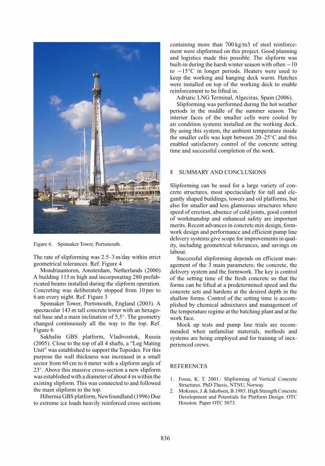
Figure 6. Spinnaker Tower, Portsmouth.
The rate of slipforming was 2.5–3 m/day within strictgeometrical tolerances. Ref. Figure 4
Mondriaantoren, Amsterdam, Netherlands (2000)A building 115 m high and incorporating 280 prefab-ricated beams installed during the slipform operation.Concreting was deliberately stopped from 10 pm to6 am every night. Ref. Figure 3
Spinnaker Tower, Portsmouth, England (2003). Aspectacular 143 m tall concrete tower with an hexago-nal base and a main inclination of 5,5◦. The geometrychanged continuously all the way to the top. Ref.Figure 6
Sakhalin GBS platform, Vladivostok, Russia(2005). Close to the top of all 4 shafts, a “Leg MatingUnit” was established to support the Topsides. For thispurpose the wall thickness was increased in a smallsector from 60 cm to 6 meter with a slipform angle of23◦. Above this massive cross-section a new slipformwas established with a diameter of about 4 m within theexisting slipform. This was connected to and followedthe main slipform to the top.
Hibernia GBS platform, Newfoundland (1996) Dueto extreme ice loads heavily reinforced cross sections
containing more than 700 kg/m3 of steel reinforce-ment were slipformed on this project. Good planningand logistics made this possible. The slipform wasbuilt-in during the harsh winter season with often −10to −15◦C in longer periods. Heaters were used tokeep the working and hanging deck warm. Hatcheswere installed on top of the working deck to enablereinforcement to be lifted in.
Adriatic LNG Terminal, Algeciras, Spain (2006).Slipforming was performed during the hot weather
periods in the middle of the summer season. Theinterior faces of the smaller cells were cooled byair condition systems installed on the working deck.By using this system, the ambient temperature insidethe smaller cells was kept between 20–25◦C and thisenabled satisfactory control of the concrete settingtime and successful completion of the work.
8 SUMMARY AND CONCLUSIONS
Slipforming can be used for a large variety of con-crete structures, most spectacularly for tall and ele-gantly shaped buildings, towers and oil platforms, butalso for smaller and less glamorous structures wherespeed of erection, absence of cold joints, good controlof workmanship and enhanced safety are importantmerits. Recent advances in concrete mix design, form-work design and performance and efficient pump linedelivery systems give scope for improvements in qual-ity, including geometrical tolerances, and savings onlabour.
Successful slipforming depends on efficient man-agement of the 3 main parameters; the concrete, thedelivery system and the formwork. The key is controlof the setting time of the fresh concrete so that theforms can be lifted at a predetermined speed and theconcrete sets and hardens at the desired depth in theshallow forms. Control of the setting time is accom-plished by chemical admixtures and management ofthe temperature regime at the batching plant and at thework face.
Mock up tests and pump line trials are recom-mended when unfamiliar materials, methods andsystems are being employed and for training of inex-perienced crews.
REFERENCES
1. Fossa, K. T. 2001.: Slipforming of Vertical ConcreteStructures. PhD Thesis, NTNU, Norway.
2. Moksnes, J. & Jakobsen, B.1985. High Strength ConcreteDevelopment and Potentials for Platform Design. OTCHouston. Paper OTC 5073.
836